1
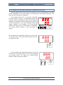
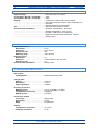
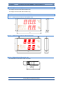
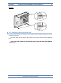
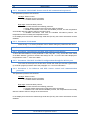
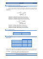
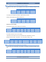
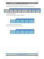
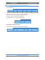
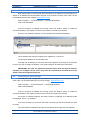
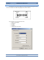
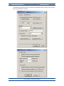
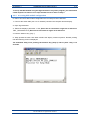
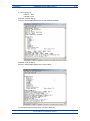
USER MANUAL DC-24 and DC-25 Thermometer and hygrometer 1600K24A Content 1. INTRODUCTION AND GENERAL CHARACTERISTICS ......................................................................... 1-1 1.1. Characteristics of the DC-24 and DC-25 displays ............................................................................ 1-2 1.2. Temperature and humidity sensor characteristics. ........................................................................... 1-2 1.3. Analog input characteristics. ............................................................................................................. 1-2 1.4. Weight of the displays. ...................................................................................................................... 1-3 1.5. Dimensions of the DC-24 and DC-25. .............................................................................................. 1-3 1.5.1. Dimensions of the DC-24S and DC-25S. ................................................................................. 1-3 1.5.2. Dimensions of the DC-24D and DC-25D. ................................................................................. 1-3 1.5.3. Dimensions of the sensor case................................................................................................. 1-3 1.6. 2. 3. Display mounting .............................................................................................................................. 1-4 1.6.1. Mounting of the DC-24S and DC-25S. ..................................................................................... 1-4 1.6.2. Mounting of the DC-24D and DC-25D. ..................................................................................... 1-5 INSTALLATION ......................................................................................................................................... 2-1 2.1. Accessing inside the display. ............................................................................................................ 2-1 2.2. Powering the display. ........................................................................................................................ 2-1 2.3. Connexion of the sensors in the displays with analog input. ............................................................ 2-2 2.4. Serial line connection. ....................................................................................................................... 2-2 2.5. Placing the sensor. ........................................................................................................................... 2-2 OPERATION. ............................................................................................................................................ 3-1 3.1. Initial reset. ....................................................................................................................................... 3-1 3.1.1. 3.2. Programming parameters ................................................................................................................. 3-1 3.2.1. 3.3. Displays with several sensors................................................................................................... 3-1 Modify parameters RS-485, Ethernet or Wifi. ........................................................................... 3-2 RS-485 parameters. ......................................................................................................................... 3-3 3.3.1. Parameter 1 for RS-485: Address of the display. ..................................................................... 3-3 3.3.2. Parameter 2 for RS-485: Serial line configuration. ................................................................... 3-3 3.3.3. Parameter 3 for RS-485: Sensor control and communication protocol .................................... 3-4 3.3.4. Parameter F: Exit menu ............................................................................................................ 3-4 3.4. Parameters Ethernet and Wifi. ......................................................................................................... 3-4 3.4.1. Parameter 1 for Ethernet and Wifi: MAC address of the display. ............................................. 3-4 3.4.2. Parameter 2 for Wifi: Load the IP configuration through the RS-232 port. ............................... 3-4 3.4.3. Parameter 3 for Ethernet and Wifi: Sensor control and communication protocols................... 3-4 3.4.4. port. Parameter 4 for Ethernet and Wifi: Load the default port configuration in the Ethernet or Wifi 3-5 3.4.5. Parameter F: Exit menu. ........................................................................................................... 3-5 3.5. 4. Modify parameters for the analog inputs. ......................................................................................... 3-5 3.5.1. Parameters of the analog inputs. .............................................................................................. 3-6 3.5.2. Default settings. ........................................................................................................................ 3-6 3.5.3. Error codes. .............................................................................................................................. 3-6 COMUNCATION PROTOCOLS................................................................................................................ 4-1 4.1. ASCII protocol for RS-485 ................................................................................................................ 4-1 4.1.1. Displays DC-24/X. Read values from the display ..................................................................... 4-2 4.1.2. Displays DC-25/X. Send values to the display ......................................................................... 4-2 4.2. PROTOCOL MODBUS RTU - ASCII for RS-485 ............................................................................. 4-4 4.3. PROTOCOL MODBUS RTU - Word for RS-485 .............................................................................. 4-6 4.4. TCP/IP, UDP/IP PROTOCOL ........................................................................................................... 4-8 4.4.1. UDP protocol ............................................................................................................................ 4-8 4.4.2. Read values from the display ................................................................................................... 4-8 4.4.3. Send values to the display. Displays without sensor. ............................................................... 4-9 4.5. ModBus/TCP PROTOCOL ............................................................................................................. 4-10 4.5.1. Modbus/TCP protocol ............................................................................................................. 4-10 4.5.2. Read data from the display ..................................................................................................... 4-10 4.5.3. Send temperature and humidity ............................................................................................. 4-11 4.1. IP Address. Ethernet option ............................................................................................................ 4-13 4.2. Modifying the port settings. ............................................................................................................. 4-13 4.2.1. 4.3. UDP/IP configuration .............................................................................................................. 4-14 IP address. Wifi. .............................................................................................................................. 4-15 4.3.1. Accessing Wifi module configuration ...................................................................................... 4-17 4.4. Set up IP Address using the DeviceInstaller. ................................................................................. 4-20 4.5. Modifying the port settings. ............................................................................................................. 4-20 CHAPTER 1 INTRODUCTION AND GENERAL CHARACTERISTICS 1-1 1. INTRODUCTION AND GENERAL CHARACTERISTICS Numerical displays DC-24 and DC-25 are displays for the accomplishment of the Real Decreto 1826/2009, in the section relative to the temperature and humidity displaying in the public access locals with air-conditioning. DC-24 displays admit form 1 to 5 sensors, calculating the mean value of all them. It automatically detects the number of sensors and displays its state once the display is initialized. The temperature and humidity sensor is placed in a case that permits a very easy installation using the support included in the package. The recommended position of the sensor is at 1,7m from the floor. The display can include RS-485, Ethernet or Wifi connectivity as options. °C % OPTIONS: RS-485 Ethernet WIFI DC-25 displays are aesthetically identical to the DC-24 but do not have sensor. They must receive the data from RS485, Ethernet or Wifi. °C % RS-485 Ethernet WIFI DC-24/A displays are aesthetically identical to the DC-24 but they have an analogical input 0-10V for each temperature and humidity sensor. The display can include RS-485, Ethernet or Wifi connectivity as options. °C % 0-10V 0-10V Temperature Humidity DC-24 and DC-25 operation manual OPTIONS: RS-485 Ethernet WIFI 1-2 INTRODUCTION AND GENERAL CHARACTERISTICS CHAPTER 1 1.1. Characteristics of the DC-24 and DC-25 displays Supply Voltage........................................... 88 to 264 VAC 47 to 63Hz. Consumption DC-24S and DC-25S .......... 12VA. Consumption DC-24S and DC-25S .......... 24VA. Display ....................................................... 7 segments, 100mm high + decimal point. ..................................................................... LED colour red, blue, white or green depending on ..................................................................... the model ..................................................................... Viewing distance: max 50 meters. Text ............................................................. Silkscreen with maximum limits. Environmental Conditions ........................ Operation Temperature: -20 to 60ºC. ..................................................................... Storage temperature: -30ºC to 70ºC. ..................................................................... Humidity: 5-95% RH non condensing. ..................................................................... Maximum environmental illumination: 1000 lux. ..................................................................... Sealing: IP41 . 1.2. Temperature and humidity sensor characteristics. Temperature sensor Resolution .......................................... 0.1°C Precision ............................................ ±0.5° at 25°C Response time ................................... 20s Working range ................................... -20°C to 80°C Humidity sensor Resolution .......................................... 1% Precision ............................................ ±3.5% between 30% and 70% Response time ................................... 4 s Environmental Conditions ..................... Sealing: IP65 . 1.3. Analog input characteristics. Input signal Configuration ..................................... Differential asymmetrical. Voltage input Range ................................................. ±10V DC Resolution .......................................... 0.5 mV Input impedance ................................ 1 MOhm Accuracy to 22° ±5°C Maximum error ................................. ±(0,1% of reading + 3 digits) Temperature coefficient ................... 100ppm/°C Warm up time ..................................... 5 minutes Conversion method Technique .......................................... Sigma-Delta Resolution .......................................... 16 bits Rate ..................................................... 25 samples/s Display Temperature resolution .................... -9.9 / 99.9. Humidity resolution ........................... 0 / 99. DC-24 and DC-25 operation manual CHAPTER 1 INTRODUCTION AND GENERAL CHARACTERISTICS 1-3 1.4. Weight of the displays. The weight of the DC-24S and DC-25S is 5kg. The weight of the DC-24D and DC-25D is 7kg. 1.5. Dimensions of the DC-24 and DC-25. 1.5.1. Dimensions of the DC-24S and DC-25S. 320 °C Max. 21°C Min. 26°C Hr 30-70% % 22 520 1.5.2. Dimensions of the DC-24D and DC-25D. 320 °C Max. 21°C Min . 26°C Hr30-70% % 520 1.5.3. Dimensions of the sensor case The dimensions of the sensor case in mm are: DC-24 and DC-25 operation manual 80 40 1-4 INTRODUCTION AND GENERAL CHARACTERISTICS CHAPTER 1 1.6. Display mounting 1.6.1. Mounting of the DC-24S and DC-25S. The DC-24S and DC-25S displays can be fixed to the wall in two ways: 1– Hanged. Place 2 of the supplied plug at 410mm from one to the other. Insert the screws leaving their head outside for 4mm. Hang the display using the upper-side zig-zag. 2– Screwed. Remove the methacrylate cover. Place the 4 supplied plugs at the distance showed in the drawing. Place the 2 upper screws, leaving their head outside for 4 mm. Hang the display using the upper-side zig-zag. Place the lower screws Tighten all the screws. Replace the methacrylate cover. The screws and plugs are provided with the display 410 289 4 Fixation Points Hanged: PARED 4 mm DC-24 and DC-25 operation manual CHAPTER 1 INTRODUCTION AND GENERAL CHARACTERISTICS 1-5 Screwed: PARED 1.6.2. Mounting of the DC-24D and DC-25D. The DC-24D and DC-25D displays must be hanged using the rings the display has. Cables or chains can be used The power cables and the sensor can be fixed to the mounting elements without tightening them. IN ANY WAY THE POWER OR THE SENSOR CABLES CAN BE USED FOR HANGING THE DISPLAY DC-24 and DC-25 operation manual CHAPTER 2 INSTALLATION 2-1 2. INSTALLATION The installation of the DC-24 and DC-25 is not particularly delicate but some important considerations must be taken into account. The display must not be anchored to places subject to vibrations, nor should it be installed in places which generally surpass the limits specified in the display characteristics, both in terms of temperature and humidity. The degree of protection of displays DC-24 and DC-25 is IP41, meaning that they are protected against penetration by solid foreign objects of a diameter of about 1mm and against the vertical fall of water droplets. Sealing of the sensor case is IP65, what means that is completely isolated from dust and jets of water Displays DC-24 and DC-25 should not be installed in places with an illumination level in excess of 1000 lux. Neither should the display be placed in direct sunlight as visibility would be lost. 2.1. Accessing inside the display. The access to the interior of the display is only authorised to technical staff. The interior must be accessed only for installation and maintenance purposes only. Disconnect the power of the display before its manipulation To access the interior, unscrew the 4 screws placed in both sides (2 screws per side) Allen key 2mm. 2.2. Powering the display. Power supply must be from 100VAC to 240VAC, 50/60 Hz. You must use a Schuko type plug that has grounded terminal. In case you have to lengthen the cord, the connection must be made on the terminal located within the display. In two-sided displays, DC-24D and DC-25D, the powering cable enters in the display through a gland. DC-24 and DC-25 operation manual 2-2 INSTALLATION CHAPTER 2 2.3. Connexion of the sensors in the displays with analog input. In all the assemblies, the inputs connection must be done using a twisted and shielded cable. The shield must be connected to the clamp 1 of the input connector. J2 Ground -IN +IN Temperature +IN Humidity No connection No connection -IN +IN (T) +IN (H) NC NC 1= 2= 3= 4= 5= 6= 1 2 3 4 5 6 12 3 4 5 6 J2 TEMPERATURE SENSOR 0-10V -OUT +OUT HUMIDITY SENSOR 0-10V -OUT +OUT 2.4. Serial line connection. The displays of the series DC-24X and DC-25X admit connection through the RS-485 line. The connection must be done using a DB9 connector placed in the interior of the display The connection schematic is the one that follows DB9 Plug 1 2 3 4 5 6 7 8 9 A B RS-485 2.5. Placing the sensor. The temperature and humidity sensor is placed in a black nylon part, protected by a cap that permits the humidity to pass through but not water. The connexion cable enters through a gland. The set must not be manipulated to keep the IP65 sealing. Slot for mounting on support DC-24 and DC-25 operation manual CHAPTER 2 INSTALLATION 2-3 In the displays with more than one sensor, there is no order or priority. There can be connected between 1 and 5 sensors in any of the connectors. The display detects the sensor when powering on the display. The temperature and humidity sensor should be placed at 1,7m high from the floor. Due to the fact that the display is expected to be in crowded places, it is recommended to protect the cable of the sensor using a tube. In the sensor placing must be avoided: 1. 2. 3. 4. The air streams due to doors Placing it in climate control systems outputs Proximity to fridges Walls with direct sunlight In case the sensor cable must be extended, the colours of the cables must be respected. The colour identification is BL = White MAR = Brown VER = Green AMA = Yellow The cable type must be YCY 4 x 0.22 shielded DC-24 and DC-25 operation manual CHAPTER 3 OPERATION 3-1 3. OPERATION. 3.1. Initial reset. Before connecting the display to the network, we must ensure that all of the connections have been carried out correctly and that the display is firmly in place. Each time we connect the display to the power supply network, an initial reset occurs which tests all of the segments comprising the display. The test consists of the sequential illumination of all of the digits with the number "8", all of the digits with the value "0", all of the decimal points are lit up and finally the version code. From this point, the DC-24 displays show the active sensors (activated = 1, deactivated = 0) and then the current temperature and the humidity In the DC-25 displays, the version code is displayed until the first message with data is received. In the DC-24A and DC-25A, the measures from the inputs are displayed. 3.1.1. Displays with several sensors. In the displays with several sensors, the displayed value is the mean value of the sensed by the connected sensors, The display detects the connected sensors and calculates the mean value depending on the active sensors. If when powering up there is no sensor detected, “0” is displayed in the 5 digits. If once the display is initialized there is no sensor detected, “E02” is displayed instead of the temperature 3.2. Programming parameters Displays with connectivity options or analog inputs must be programmed previously to its use. The parameters the user must configure are: Displays with RS-485 serial line 1- Address of the display in the network. 2- Transmission baud rate, data bits, parity, stop bits. 3- Sensor control and communication control: ASCII, Modbus RTU-ASCII, Modbus RTU-Word F- Quit menu. Press “*” Displays with Ethernet and Wifi 1- Display the MAC address of the display 2- No use. 3- Sensor control and communication protocol: TCP/IP and Modbus/TCP 4- Reset communications port. F- Quit menu. Press “*” DC-24 and DC-25 operation manual 3-2 OPERATION CHAPTER 3 Displays with analog input. In the displays with analog input, the user must define 2 points of the line that determine all the values. Every point is set by 2 voltages and 2 displaying values. There must be a line for temperature and another for humidity. 12345678- Input voltage for the first point of the line. Temperature Displayed value for the first point of the line. Temperature Input voltage for the second point of the line. Temperature Displayed value for the second point of the line. Temperature Input voltage for the first point of the line. Humidity Displayed value for the first point of the line. Humidity Input voltage for the second point of the line. Humidity Displayed value for the second point of the line. Humidity 3.2.1. Modify parameters RS-485, Ethernet or Wifi. To modify the parameters the user must access the three programming keys placed on the top inside the display. See paragraph 3.1 to see how to access inside the display. The programmation keys are placed in the top of the displays. The identification of the keys is Advance key: “* “ Increase key: “+” To program the parameters, the three digits on the top are used. The left digit, identificated with the digital point, indicates the parameter number and the two right digits indicate its value. The flashing digit is the one the user can modify with the “+” key To enter the menu, main the “*” key pressed for 3 seconds. Once this time is passed, the first parameter is displayed. There are then two options: 1- Modify the parameter value By pressing the Advance key "*", entry is gained to modify the parameter value. To go back to displaying the parameter number, press “*”again. To increase the parameter value, press the “+” key. 2- Select another parameter In order to select another parameter, the parameter number must be made to flash using the “*” key and then the new parameter may be selected using the “+” key. DC-24 and DC-25 operation manual CHAPTER 3 OPERATION 3-3 3.3. RS-485 parameters. 3.3.1. Parameter 1 for RS-485: Address of the display. It allows to configurate the address of the display in the RS-485 network. Value between 0 and 99. 3.3.2. Parameter 2 for RS-485: Serial line configuration. The parameters of the serial line are codified in the following table: Code 01 02 03 04 05 06 07 08 09 10 11 12 13 14 15 16 17 18 19 20 21 22 23 24 25 26 27 28 29 30 31 32 33 34 35 36 Baud Rate 4800 Bauds 9600 Bauds 19200 Bauds 4800 Bauds 9600 Bauds 19200 Bauds 4800 Bauds 9600 Bauds 19200 Bauds 4800 Bauds 9600 Bauds 19200 Bauds 4800 Bauds 9600 Bauds 19200 Bauds 4800 Bauds 9600 Bauds 19200 Bauds 4800 Bauds 9600 Bauds 19200 Bauds 4800 Bauds 9600 Bauds 19200 Bauds 4800 Bauds 9600 Bauds 19200 Bauds 4800 Bauds 9600 Bauds 19200 Bauds 4800 Bauds 9600 Bauds 19200 Bauds 4800 Bauds 9600 Bauds 19200 Bauds Data bits 7 bits 7 bits 7 bits 8 bits 8 bits 8 bits 7 bits 7 bits 7 bits 8 bits 8 bits 8 bits 7 bits 7 bits 7 bits 8 bits 8 bits 8 bits 7 bits 7 bits 7 bits 8 bits 8 bits 8 bits 7 bits 7 bits 7 bits 8 bits 8 bits 8 bits 7 bits 7 bits 7 bits 8 bits 8 bits 8 bits Parity No parity No parity No parity No parity No parity No parity Even Even Even Even Even Even Odd Odd Odd Odd Odd Odd No parity No parity No parity No parity No parity No parity Even Even Even Even Even Even Odd Odd Odd Odd Odd Odd Table 1: RS-485 codes for configuration DC-24 and DC-25 operation manual Stop bits 1 1 1 1 1 1 1 1 1 1 1 1 1 1 1 1 1 1 2 2 2 2 2 2 2 2 2 2 2 2 2 2 2 2 2 2 3-4 OPERATION CHAPTER 3 3.3.3. Parameter 3 for RS-485: Sensor control and communication protocol This parameter performs two functions Left digit: Sensor control 0-> Disable sensor information 1 -> Enable sensor information Right digit: Communication protocol, The user can select between the following protocols: 0: ASCII: Really simple protocol that uses ASCII characters 1: ModBus RTU-ASCII: This uses the ModBus protocol, but the temperature and humidity data are coded in ASCII in the same block. 2: ModBus RTU-Word. This uses the ModBus RTU-Word protocol. The temperature and the humidity are independent words. In the display that receives the data through serial line (DC-25), the sensor information must be disabled. 3.3.4. Parameter F: Exit menu Press the key “*” to exit the parameter menu. Before exiting the parameters are saved. 3.4. Parameters Ethernet and Wifi. 3.4.1. Parameter 1 for Ethernet and Wifi: MAC address of the display. To know the MAC address, access parameter 1 and, using the “*” key, access the 3 last values of the MAC address. The first 3 numbers are always 00 -20 - 4A, so the first value displayed in th the parameter is the 4 value of the MAC. 3.4.2. Parameter 2 for Wifi: Load the IP configuration through the RS-232 port. To access the serial port for the first time, the RS-232 serial port and the Hyperterminal (or a similar program) must be used. See paragraph 4.7.1 for more information. 3.4.3. Parameter 3 for Ethernet and Wifi: Sensor control and communication protocols. This parameter performs two functions Left digit: Sensor control 0-> Disable sensor information 1 -> Enable sensor information Right digit: Communication protocol, The user can select between the following protocols: 0: TCP/IP: Really simple protocol that uses ASCII characters 1: ModBus TCP: This uses the ModBus protocol, the temperature and humidity data are coded in ASCII or integer in the same block. In the display that receives the data through serial line (DC-25), the sensor information must be disabled. DC-24 and DC-25 operation manual CHAPTER 3 OPERATION 3-5 3.4.4. Parameter 4 for Ethernet and Wifi: Load the default port configuration in the Ethernet or Wifi port. To load the default values in the communication port, program the value 99 and press the “*” key. During the load time, the digits “99” are flashing. When it has finished, the parameter 4 is displayed again. 3.4.5. Parameter F: Exit menu. Press the key “*” to exit the parameter menu. Before exiting the parameters are saved. 3.5. Modify parameters for the analog inputs. The analog inputs must be configured to adapt the display to the specifications of the analog sensor To modify the parameters the user must access the three programming keys placed on the top inside the display. See paragraph 3.1 to see how to access inside the display. The programmation keys are placed in the top of the displays. The identification of the keys is Advance key: “* “ Increase key: “+” Validate key “E” To program the parameters, the three digits on the top are used. The left digit, identified with the digital point, indicates the parameter number and the two right digits indicate its value. The flashing digit is the one the user can modify with the “+” key. Press the “*” key to change the digit to modify. Accept the value with the “E” key. To enter the menu, main the “*” key pressed for 3 seconds. Once this time is passed, the first parameter is displayed. There are then two options: 1- Modify the parameter value By pressing the Advance key "*", change the digit to the one you want to modify. To increase the parameter value, press the “+” key. To validate the parameter value, press the “E” key 2- Select another parameter In order to select another parameter, the parameter number must be made to flash using the “*” key and then the new parameter may be selected using the “+” key. DC-24 and DC-25 operation manual 3-6 OPERATION CHAPTER 3 3.5.1. Parameters of the analog inputs. Remember that the left digit of the parameter 3 must be 1. For each of the sensors, temperature and humidity, 4 parameters must be programmed, so they define 2 points of a line. For each point a voltage level and the value to display must be programmed. b2 Temperatura b1 A1 Tension A2 Parameter A1: Temperature. Input voltage for the first point. Parameter b1: Temperature. Displayed value for the first point. Parameter A2: Temperature. Input voltage for the second point. Parameter b2: Temperature. Displayed value for the second point. d2 Humedad d1 C1 Tension C2 Parameter C1: Humidity. Input voltage for the first point. Parameter d1: Humidity. Displayed value for the first point. Parameter C2: Humidity. Input voltage for the second point. Parameter d2: Humidity. Displayed value for the second point. 3.5.2. Default settings. The displays are provided with the following values Temperature Parameter A1 = 0.0 V Parameter b1 = -9.9°C Humidity Parameter C1 = 0.0 V Parameter d1 = 0% 3.5.3. Error codes. The display can detect any malfunction, so they are displayed and codified as the following table Correct value Value ≥ 100ºC Value ≤ -10,0ºC Value ≥ 100% Value <20% Error on the parameters Input voltage < minimum Input voltage > maximum Temperature E10 E20 E30 E40 E50 E60 Humidity E01 E02 E03 E04 E05 E06 If there is error in both sensors, the displayed value is the addition of both errors. If there is only one error, a “1” is seen in the sensor that works correctly and the error code in the other sensor For example: Parameter error in both sensors. Displayed value: E44. Error in the temperature sensor. Displayed value: E41. DC-24 and DC-25 operation manual CHAPTER 4 COMMUNICATION PROTOCOLS 4-1 4. COMUNCATION PROTOCOLS In this paragraph, the different protocols will be explained, as well as the programmation of the displays through them. The formats of values of the numbers and characters are written in this manual are: When telling about a hexadecimal number, this will be followed by an “h”. When telling about a decimal number, this will be followed by a “d”. When telling about a binary number, this will be followed by a “b”. When telling about an ASCII character, this will be explained in the context. As an example, the X ASCII character can be explained as 58h, 88d or 1011000b, as needed in the moment. Number 15 ASCII can be seen as 31h 35h, 49d 53d or 110001d 110101d. 4.1. ASCII protocol for RS-485 This protocol allows communicating with any device that disposes serial line and can configure the communication protocol, as a PC or PLC. There can be 99 devices connected to the net with the corresponding amplifiers every 30 devices. Using this protocol forces the display to work on slave mode. This means that the display waits for a message and, once verified, it responds depending on the command received. To understand how to configure the protocol, the used terms are used Message. It is formed by all the necessary characters to establish the dialogue. For each correct message received, the display returns a response message. The message consists of three parts: The header, the data and the end of block Header. It is used to identify the beginning of the message. The character @ (64d, 40h) followed by the address of the display is sent. Data block: The data block can consist of commands or responses. The valid commands are the following The command PT is a request to the display to ask for the current temperature and humidity values. The command VT is an order to the display to shoe temperature and humidity values that are sent. End of block: It is used to identify the complete arrival of the block. It is used the character “Carry return” (13d 0Dh) DC-24 and DC-25 operation manual 4-2 COMMUNICATION PROTOCOLS CHAPTER 4 4.1.1. Displays DC-24/X. Read values from the display To read the current values of the temperature and humidity, the following message must be sent: Header @ 64d 40h Characters Decimal Hexadecimal Address High Low Code P T 80d 84d 50h 54h End of block Carry return 13d 0Dh The address of the display is formed by 2 digits between 0 and 99 Example: Data request to the display at address 15 Header @ 64d 40h Characters Decimal Hexadecimal Address 1 5 49d 53d 31h 35h Code P T 80d 84d 50h 54h End of block Carry return 13d 0Dh Response from the display The response message from the display is the following: Header @ 64d 40h Characters Decimal Hexadecimal Address High Low Code P T 80d 84d 50h 54h Temp TT,T Space Hum HH 32d 20d End of block Carry return 13d 0Dh The address returned is the one of the display Temperature and humidity are sent in the indicated format, separated by a comma. Response frame example. Temperature = 24,7 and relative humidity = 63% Header Characters Address Code Temp Space Hum End of block 63 Carry return @ 1 5 P T 24,7 Decimal 64d 49d 53d 80d 84d 50d 52d 44d 55d 32d 54d 51d 13d Hexadecimal 40h 31h 35h 50h 54h 32h 34h 2Ch 37h 20h 36h 33h 0Dh 4.1.2. Displays DC-25/X. Send values to the display To send values of the temperature and humidity to the display, the following message must be sent: Characters Decimal Hexadecimal Header @ 64d 40h Address High Low Code V T 86d 84d 56h 54h Temp TT,T Space 32d 20d DC-24 and DC-25 operation manual Hum HH End of block Carry return 13d 0Dh CHAPTER 4 COMMUNICATION PROTOCOLS 4-3 The address of the display is formed by 2 digits between 0 and 99 Example: Data sent to the address 04. Temperature 18.6°C and relative humidity 47%. Header Characters Address Code Temp Space Hum End of block @ 1 5 V T 18,6 47 Carry return Decimal 64d 49d 53d 86d 84d 49d 56d 44d 54d 32d 52d 55d 13d Hexadecimal 40h 31h 35h 56h 54h 31h 38h 2Ch 36h 20h 34h 37h 0Dh Response from the display The response message from the display is the following: Characters Decimal Hexadecimal Header @ 64d 40h Address High Low Code V T 86d 84d 56h 54h End of block Carry return 13d 0Dh Code V T 86d 84d 56h 54h End of block Carry return 13d 0Dh The address returned is the one of the display Example: Frame returned when data has been sent Characters Decimal Hexadecimal Header @ 64d 40h Address 0 4 48d 52d 30h 34h DC-24 and DC-25 operation manual 4-4 COMMUNICATION PROTOCOLS CHAPTER 4 4.2. PROTOCOL MODBUS RTU - ASCII for RS-485 This protocol allows the user to communicate with devices that dispose of ModBus RTU protocol It uses the function 10h and the data block is in ASCII mode. The values can be read or sent. If the user wants to send the values to the display, the sensor must be disabled (see paragraph 3.3.3) To read the values from the display, the following command must be sent Addr. Func. 03h 10h 10h Register High 01h 01h Register Low 01h 01h Words High 00h 00h Words Low 01h 01h Bytes num 02h 02h Data P T 50h 54h Low CRC High CRC 93h DEh The first byte is the address of the display inside the network. The three following bytes must be 10h, 01h and 01h. The bytes 5 and 6 correspond to the number of words of the data field. In the data field the characters “PT” must be placed, so the display know the user is requesting data In the previous example, the CRC is calculated for the display at the 03 address. An example of the response of the display is the following message Addr Func. 03h 10h 10h Register High 01h 01h P T 50h 54h Register Low 01h 01h Words High 0 00h Data 23,7 32h 33h 2Eh 37h Words Low 5 05h 20h Bytes num 0Ah 0Ah 51 35h 31h 20h Low CRC High CRC D1h 19h In the response message, the received code is repeated and the temperature and humidity values are added, separated by the space character (20h). After the humidity, there is another space character (20h) so the byte number is even. If the display detects an error in the received block, the error code with the following data code is sent Address. Error 90h Error code Low CRC The possible errors are: 02 = CRC error. DC-24 and DC-25 operation manual High CRC CHAPTER 4 COMMUNICATION PROTOCOLS 4-5 To write values in the display, the following message must be sent: Addr. Func. 03h 10h 10h Register High 01h 01h V T 56h 54h Register Low 01h 01h Words High 0 00h Data 25,3 32h 35h 2Ch 33h Words Low 5 05h 20h Num. bytes 0Ah 09h 47 34h 37h 00h LOW CRC High CRC F4h 9Ch The first byte is the address of the display inside the network. The three following bytes must be 10h, 01h and 01h. The bytes 5 and 6 correspond to the number of words of the data field. In the data field the characters “VT” must be placed, followed by the temperature and humidity data. At the end, a 00h character must be sent so the number of byte sent is even. The response from the display is the following message: Addr. Func. 03h 10h 10h Register High 01h 01h Register Low 01h 01h Words High 00h 00h Words Low 01h 01h Num. bytes 02h 02h Data V T 56h 54h Low CRC High CRC 90h 7Eh In the response message, the received code is repeated until the control code (V). If the display detects an error in the received block, the error code with the following data code is sent Addr. Error 90h Error code Low CRC The possible errors are: 02 = CRC error. DC-24 and DC-25 operation manual High CRC 4-6 COMMUNICATION PROTOCOLS CHAPTER 4 4.3. PROTOCOL MODBUS RTU - Word for RS-485 This protocol allows the user to communicate with devices using the protocol Modbus RTU This protocol uses the function 06h to write and the function 03h to read data from the display. The data block is a Word. The user can write or read data. If the data must be sent, the sensor mist be disabled modifying the parameter 3. See paragraph 3.3.3 “Parameter 3 for RS-485: Sensor control and communication protocol” The temperature is sent multiplied per 10 when writing or reading. As an example 21,6 ºC will be sent as 216 (00D8h) To write the temperature value, the data must be sent to register 0001h (40001h). The data format must be 16-bit word format. In the following example, the data block structure is detailed for a 19,7ºC (00C5h) temperature writing. Func. 06h Reg. H 00h Reg. L 00h Data 00h C5h Low CRC 48h High CRC 7Bh To write the humidity value, the data must be sent to register 0002h (40002h). The data format must be 16-bit word format. In the following example, the data block structure is detailed for 57% (0039h) humidity writing. Func. 06h Reg. H 00h Reg. L 01h Data 00h 39h Low CRC 19h High CRC FAh If the data block is correctly received, the display responds with the same data block it has received If there is an error in the reception, the display responds with an error detection block with the following data. Addr. Error 86h Error code CRC low CRC high The possible errors are: 02 = CRC error. To read the temperature value, the data request must be sent to register 0003h (40003h). In the following example, the data block structure is detailed for a temperature request. Addr. Func. 03h 03h Start Addr. H 00h Start Addr. L 02h Num. Reg. H. 00h Num. Reg. L. 01h Low CRC High CRC 24h 28h If the block is correctly received, the display responds with the temperature value in 16bit Word format. Remember that the temperature is multiplied per 10. DC-24 and DC-25 operation manual CHAPTER 4 COMMUNICATION PROTOCOLS 4-7 Response block example. Temperature: 23,8ºC Addr. 03h Func. 03h Num. bytes 02h Data 00h EEh Low CRC 41h High CRC C8h To read the humidity value, the data request must be sent to register 0004h (40003h). In the following example, the data block structure is detailed for a humidity request. Addr. Func. 03h 03h Start Addr. H 00h Start Addr. L 03h Num. Reg. H. 00h Num. Reg. L. 01h Low CRC High CRC 75h E8h If the block is correctly received, the display responds with the humidity value in 16-bit Word format. Response block example. Humidity: 52% Addr. 03h Func. 03h Num. bytes 02h Data 00h 34h Low CRC C0h High CRC 53h If there is an error in the reception, the display responds with an error detection block with the following data. Addr. Error 83h Error code CRC low DC-24 and DC-25 operation manual CRC high 4-8 COMMUNICATION PROTOCOLS CHAPTER 4 4.4. TCP/IP, UDP/IP PROTOCOL The display only accepts frames ending with a block ending it can see. (End of clock = Carry return = 0Dh) Local Port = 10001. 4.4.1. UDP protocol To use the UDP protocol, the communication port must be programmed with the default configuration To use UDP/IP, the Local Port must be 10001 UDP Datagram Mode Datagram Type must be 01. Active Connection Remote Host: IP address of the PC to which the display is connected. Remote Port: Port of the PC to which the display is connected. 4.4.2. Read values from the display To read the current temperature and humidity the following frame must be sent: Characters Decimal Hexadecimal Code P T 80d 84d 50h 54h End of Block Carry return 13d 0Dh Response from the display The response frame from the display is the following: Characters Decimal Hexadecimal Code P T 80d 84d 50h 54h Temperature TT.T Space Humidity HH 32d 20h End of block Carry return 13d 0Dh Response block in protocols TCP/IP and UDP/IP. Example. Frame returned by the display with values 24.7ºC and 63% In protocol ModBus/TCP the characters PT are not returned Characters Decimal Hexadecimal Code P T 80d 84d 50h 5h4 Temperature 24,7 50d 52d 44d 55d 32h 34h 2Ch 37h Space 32d 20h Humidity 63 54d 51d 36h 33h DC-24 and DC-25 operation manual End of Block Carry return 13d 0Dh CHAPTER 4 COMMUNICATION PROTOCOLS 4-9 4.4.3. Send values to the display. Displays without sensor. To send the temperature and humidity values to a display without sensor, the following block must be sent Characters Decimal Hexadecimal Code V T 86d 84d 56h 54h Temperature TT.T Space Humidity HH 32d 20h End of Block Carry return 13d 0Dh Response block in protocols TCP/IP and UDP/IP. Example. The response block from the display is the following In the ModBus/TCP protocol, the field “Data” is empty. Characters Decimal Hexadecimal Code V T 86d 84d 56h 54h End of Block Carry Return 13d 0Dh Sending data to the display. Example Example with the values 23.6ºC temperature and 58% humidity. Characters Decimal Hexadecimal Code V T 86d 84d 56h 54h Temperature 23,6 50d 51d 44d 54d 32h 33h 2Ch 36h Space 32d 20h Humidity 58 53d 56d 35h 38h DC-24 and DC-25 operation manual End of Block Carry return 13d 0Dh 4-10 COMMUNICATION PROTOCOLS CHAPTER 4 4.5. ModBus/TCP PROTOCOL The frame must accomplish the ModBus/TC specifications for being accepted by the display. 4.5.1. Modbus/TCP protocol End of block is not necessary. Local Port = 502. 4.5.2. Read data from the display To read the current temperature and humidity, the functions 03h or 10h must be used. The blocks are the following Function 03h. The temperature is in register 40003 (address 02h) and the humidity in the register 40004 (address 03h) Read temperature: Identifier Protocol 08h 62h 00h 00h Number of bytes 00h 06h Unit Function 01h 03h Start address 00h 02h Number of registers 00h 01h Response from the display The response frame from the display is the following. In this example, the identifier is 0862h and the read temperature is 20.5ºC = CDh Identifier Protocol 08h 62h 00h 00h Number of bytes 00h 05h Unit Function 01h 03h Number of registers 02h Data 00h CDh Read temperature and humidity Temperature and humidity can be read reading 2 registers from the register 40003. In this example, the identifier is 0618h, the read temperature is 20.5ºC (CDh) and the humidity is 42% (1Ah) Sent frame: Identifier Protocol 06h 18h 00h 00h Number of bytes 00h 06h Unit Function 01h 03h Start address 00h 02h Number of registers 00h 02h Response from the display Identifier Protocol 06h 18h 00h 00h Number of bytes 00h 07h Unit Function 01h 03h Number of registers 04h DC-24 and DC-25 operation manual Data 00h CDh 00h 2Ah CHAPTER 4 COMMUNICATION PROTOCOLS 4-11 Function 10h Temperature and humidity can be read using the function 10h. In the frame, the following codes must be codified. Unit = 01h Function = 10h Start address = 00h 00h Identifier Protocol 01h 0Ah 00h 00h Num bytes 00h 09h Unit Function 01h 10h Start addr 00h 00h Num. regist. 00h 01h Num. Bytes 02h Data 50h 54h In the data field, the characters PT (50h 54h) must be sent. Response from the display. Example. In this frame, the data received are 20.4ºC and 42% Identifier Protocol 01h 0Ah 00h 00h Number bytes 00h 0Dh Unit Function 01h 10h Data 32h 30h 2Eh 34h 20h 34h 32h 00h 00h 00h 01h 4.5.3. Send temperature and humidity In the repeater displays, the temperature and humidity can be sent using the function 06h or 10h. Function 06h. The temperature must be sent to the register 40003 (address 02h) and the humidity must be sent to the register 40004 (address 03h). In this example, the identifier is 0618h and the temperature sent is 21.1ºC (D3h) Frame to send: Identifier Protocol Num. Bytes Unit Function Start address Num. registers 00h 32h 00h 00h 00h 06h 01h 06h 00h 02h 00h D3h Response from the display: The response from the display is the same block sent. DC-24 and DC-25 operation manual 4-12 COMMUNICATION PROTOCOLS CHAPTER 4 Function 10h mode ASCII Sending temperature and humidity using the function 10h. In the frame, the following codes must be codified. Unit = 01h Function = 10h Start address = 00h 00h Identifier 00h 37h Protocol 00h 00h Num. bytes 00h 11h Num. Registers 00h 05h Num. Bytes 0Ah Unit 01h Function 10h Data 56h 54h Start address 00h 00h Data 31h 39h 2Eh 34h 20h 35h 37h In this example, in the data field the values 19,4°C 57% must be sent. Response from the display: The response from the display is the same frame received from the identifier until the number of registers. Identifier Protocol 00h 37h 00h 00h Num. bytes 00h 11h Unit Function 01h 10h Start address 00h 00h Num. Registers 00h 05h Function 10h mode Word Sending temperature and humidity can be sent using the function 10h. In the frame, the following codes must be codified. Unit = 01h Function = 10h Start address = Register 40003 (Address 02h) Identifier 00h 37h Protocol 00h 00h Num. Bytes 00h 0Bh Unit 01h Number of registers 00h 02h Function 10h Start address 00h 02h Number of bytes 04h Data 00h F3h 00h 39h In this example, in the data field the values 19,4°C 57% must be sent. Response from the display: The response from the display is the same frame received from the identifier until the number of registers. Identifier Protocol 00h 37h 00h 00h Number of bytes 00h 0Bh Unit Function 01h 10h DC-24 and DC-25 operation manual Start address 00h 00h Number registers 00h 04h CHAPTER 4 4.1. COMMUNICATION PROTOCOLS 4-13 IP Address. Ethernet option Before being able to communicate with the display an IP address must be assigned. To assign an IP address the DeviceInstaller program from Lantronix must be used, which can be downloaded free from their website: www.lantronix.com Select: Support → Technical Support → Firmware/Downloads. Select: DeviceInstaller. Once the program is installed and running, press the “Search” button to locate the connected displays. The display must be turned on and connected to the network. If there are no network problems, a screen similar to this should be displayed. The IP address with which the equipment is supplied is: 10.30.90.10 The Hardware Address is the unit MAC code. To assign the IP address you must first select the equipment by clicking on the XPort-03 to which you wish to assign the address. Then press Assign IP and follow the instructions. IMPORTANT: All units are dispatched from the factory with the same IP address. Therefore to configure various units, they must be connected to the Ethernet and the address must be assigned one by one. 4.2. Modifying the port settings. To modify the port configuration the DeviceInstaller program from Lantronix must be used, which can be downloaded free from their website: www.lantronix.com Select: Support → Technical Support → Firmware/Downloads. Select: DeviceInstaller. Once the program is installed and running, press the “Search” button to locate the connected displays. The display must be turned on and connected to the network. If there are no network problems, the same screen for configuring an IP address should be displayed. See 4.1 “IP Address.” To access the setup you must first select the unit clicking on the XPort-03 that you wish to modify. Then press Web Configuration and the GO key placed at the right side of IP address. DC-24 and DC-25 operation manual 4-14 COMMUNICATION PROTOCOLS CHAPTER 4 Enter your computer User Name and Password. To access the setup the Local Port, select Channel1->Connection. You will see a screen similar to the one above. In Local Port insert the new value and click OK on the bottom of the page. 4.2.1. UDP/IP configuration Select Channel 1 -> Connection in the left menu. Select the UDP protocol in “Connection protocol” Select Datagram Type = 1 in Datagram Mode Introduce the following in Endpoint Configuration Local Port = 10001 Remote Port = Port of the equipment that will be connected. Remote Host = IP address of the equipment that will be connected. Click OK in the bottom of the page. Click Apply Settings in the left menu. DC-24 and DC-25 operation manual CHAPTER 4 4.3. COMMUNICATION PROTOCOLS 4-15 IP address. Wifi. The easiest way to set up the IP address is by using the Hyperterminal program and the serial line of computer. The cable’s wiring diagram is the classic crossover. DB9 o SAP12 Hembra 2 3 5 9 Visualizador DB9 Hembra 2 3 5 Ordenador The configuration of the Hyperterminal must be: Baud rate: 9600 Bauds Data Bits: 8 No parity Stop Bits: 1 Hardware flow control: None. DC-24 and DC-25 operation manual 4-16 COMMUNICATION PROTOCOLS CHAPTER 4 The attached Hyperterminal set up have been verified and work correctly, but any other set up may work also correctly. DC-24 and DC-25 operation manual CHAPTER 4 COMMUNICATION PROTOCOLS 4-17 To set up the Wifi module using the Hyperterminal or any other program, you must follow a time sequence. A time error on steps 5 and 6 forces to return to step 3. 4.3.1. Accessing Wifi module configuration In order to access to Wifi module configuration the next steps must be followed: 1– Connect the serial cable (see 4.3 “IP address”) between the computer and the display. 2– Open Hyperterminal. 3– Select the display’s parameter 7. See ¡Error! No se encuentra el origen de la referencia. REF _Ref353780144 \h ¡Error! No se encuentra el origen de la referencia. 4- Push the advance key. (Key *) 5– Keep pushed the lower case letter x before the display counters equals 0. Remain pushing until the following screen is displayed. The maximum delay since pushing the advance key (step 4) until to push x key is 10 seconds. DC-24 and DC-25 operation manual 4-18 COMMUNICATION PROTOCOLS CHAPTER 4 6– At this time you have 3 seconds to push the Intro key on your keyboard. 7– The following screen is shown. DC-24 and DC-25 operation manual CHAPTER 4 COMMUNICATION PROTOCOLS 8– You must set up: 0 Server + Intro 4 WLAN + Intro Example of Server Set up Ask your network administrator the IP and Gateway address. Example of WLAN Set up Ask your network administrator the correct values To exit select 8 (Exit without save) or 9 (Save and exit). DC-24 and DC-25 operation manual 4-19 4-20 4.4. COMMUNICATION PROTOCOLS CHAPTER 4 Set up IP Address using the DeviceInstaller. Before being able to communicate with the display an IP address must be assigned. To assign an IP address the DeviceInstaller program from Lantronix must be used, which can be downloaded free from their website: www.lantronix.com Select: Support → Technical Support → Firmware/Downloads. Select: DeviceInstaller. Once the program is installed and running, press the “Search” button to locate the connected displays. The display must be turned on and connected to the network. If there are no network problems, a screen similar to this should be displayed. The IP address with which the equipment is supplied is: 10.30.90.10 The Hardware Address is the unit MAC code. To assign the IP address you must first select the equipment by clicking on the XPort-03 to which you wish to assign the address. Then press Assign IP and follow the instructions. IMPORTANT: All units are dispatched from the factory with the same IP address. Therefore to configure various units, they must be connected to the Ethernet and the address must be assigned one by one. 4.5. Modifying the port settings. To modify the port configuration the DeviceInstaller program from Lantronix must be used, which can be downloaded free from their website: www.lantronix.com Select: Support → Technical Support → Firmware/Downloads. Select: DeviceInstaller. Once the program is installed and running, press the “Search” button to locate the connected displays. The display must be turned on and connected to the network. If there are no network problems, the same screen for configuring an IP address should be displayed. See 4.1 “IP Address.” To access the setup you must first select the unit clicking on the XPort-03 that you wish to modify. . DC-24 and DC-25 operation manual DECLARACION DE CONFORMIDAD DISEÑOS Y TECNOLOGIA, S.A. Poligon Industrial Les Guixeres C/ Xarol 8C 08915 BADALONA España As the builder of the equipment of the DITEL brand: Model : DC-24 in all versions. Model: DC-25 in all versions. We declare under our sole responsibility that the aforementioned product complies with the following European directives: Directive: LVD 2006/95/CEE Low Voltage Directive. Standard UNE-EN61010-1 Security in electric equipment. Directive: EMC 2004/108/CEE Electromagnetic Compatibility Standard UNE-EN 61000-6-4 Generic Emission Standard. Industrial environment. Standard UNE-EN 61000-6-2 Generic Immunity Standard. Industrial environment. . Badalona, 5th February 2013 Alicia Alarcia Technical Director