1
COMPUTING LINE-TO-LINE TRANSFER MATRICES WITH
EMME/2
Heinz Spiess
EMME/2 Support Center, CH-2558 Aegerten, Switzerland
March 1992
Abstract:
When assigning a transit network with EMME/2, the basic results are the volumes on the transit segments and the boardings/
alightings at the transit stops. Means to produce line-to-line transfer matrices at transfer nodes are not provided as a
standard result output.
In this paper we show how such line-to-line transfer matrices can be computed for selected transfer nodes, without changing
the assignment results. This is done with the standard EMME/2 software , by using a special network transformation at the
selected transfer nodes. Details of this transformation are discussed and we show how the process has been automated by
implementing it as a macro. The method is illustrated with an example from the Winnipeg standard demonstration data
bank.
In the conclusions we discuss how this methodology can be extended to model other complex situations which are not
covered by the standard model.
This paper was presented at the 1st European EMME/2 Users' Conference, London, April 1992
Introduction
When modelling transit networks, the basic results provided by the transit assignment in the EMME/2 software package are
the volumes on the transit line segments, as well as the boardings and alightings at each transit stop. Of course, other
information is also computed during the transit assignment, such as the number of initial boardings and final alightings at
nodes, the auxiliary link volumes (e.g. pedestrian movements) and the various OD time component matrices.
These standard results cover the need of the great majority of transit planning applications. However, in certain applications
it is not sufficient to know the total number of transfers at each transfer node, but it is necessary to assess the number of
trips that transfer at a given node from one particular line (and direction) to another. This means that instead of just the total
number of transfers at a given node, a line-to-line transfer matrix is needed. Ideally, such a transfer matrix could be
computed for each transit node in the network. But this would amount to a huge quantity of data, in general requiring orders
of magnitude more storage space than is needed for the standard assignment results. For the Winnipeg standard
demonstration network, there are 57'333 possible line-to-line transfers, but only 4'272 transit line segments. Given this and
the fact that the number of possible line-to-line transfers at a node is the square of the number of lines stopping at the node
(which by the way is not restricted in EMME/2), it is clear that these transfer matrices are not provided as a standard result
in EMME/2. However, in practice it is most always necessary to know the transfer matrices at only a few transfer nodes in
the network (which ones, of course, depend on the particular issues that are to be studied in the application).
In the past, two types of simplistic approaches to solve this problem have been used in practice by some EMME/2 users.
In the first type of methods, the network topology is changed by splitting the transfer node into different nodes which are
interconnected with a ``matrix'' of walk links. The big drawback of this approach is that this network transformation
changes the route choice and, thus, the assignment results, since the lines at the transfer node can no longer be combined to
reduce waiting time.
In the second type of approach, the network is left unchanged, but instead of a simple assignment, a series of assignments is
carried out, mimicing a transit version of an ``additional options auto assignment''. In the first step of this process, a partial
demand matrix representing the trip using a given line (or set of parallel lines) is extracted. In the second step, this matrix is
assigned again to the transit network. The resulting boardings to and alightings from the other lines passing at the transfer
node can then be interpreted as the line-to-line transfers between the selected line and the other lines calling at the transfer
node. While this method does not change the route choice of the trips, it is very time consuming (several assignments
needed), it gives only partial information relative to one line and it is only applicable if the line (or set of lines) in question
are not used combined with other lines at the transfer node.
In the following sections, we will describe a new methodology designed to overcome the problems mentioned above. The
approach allows to compute such line-to-line transfer matrices for selected nodes with the standard EMME/2 software
release, as a by-product of a single standard transit assignment. This is done by a special network transformation at the
transfer node, which does not alter the mathematical formulation of the transit assignment problem (i.e. yields the same
results as before the transformation), but which renders the line-to-line transfers accessible as boardings and alightings of
special transfer segments.
Network Representation at Transfer Node
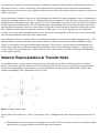
In a standard network, a transfer node is connected by incoming and outgoing links. Each link can carry an arbitrary
number of transit line segments and allow a subset of auxiliary modes for accessing to or egressing from the transit lines.
For the sake of simplifying the presentation, we assume that all lines actually stop at the transfer node and allow both
boarding and alighting. This is illustrated in Figure 1 below:
Figure 1: Simple transfer node.
The key idea of our method is to ``blow up'' the transfer node, by adding dummy nodes, links and segments in such a way
that:
●
The mathematical structure of the transit assignment is not altered. This means that no time or cost element is added
and that the new topology still allows exactly the same set of strategies.
●
The elements of the line-to-line transfer matrix appear as boardings or alightings at the dummy nodes.
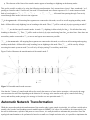
This goal is possible to achieve by using the following transformation: Let's assume that we have L lines, numbered 1 to L,
passing at a transfer node N. In this case, the node N is transformed into a linear sequence of L+2 nodes connected with
links of zero length, i.e.
. All transit lines passing through T are newly
routed through these nodes with zero time segments.
is the egress node. All incoming line segments are connected to this node, as well as are all outgoing auxiliary mode
links. All lines allow only alighting, but no boarding at this node. Thus,
are the line specific transfer nodes. At node
boarding is allowed at
. Thus,
no auxiliary modes connected to
will be used only by trips egressing at node T.
, alighting is allowed only for line
will be used exclusively by trips transferring from line
. For all other lines only
to other lines. Since there are
, no access and egress movements are possible.
is the access node. All outgoing line segments are connected to this node, as well as are all incoming and outgoing
auxiliary mode links. All lines allow only boarding, but no alighting at this node. Thus,
will be used by all trips
accessing the transit system at node T, as well as by all trips passing T on auxiliary mode links.
Figure 2 below illustrates the transformation of the transfer node T.
Figure 2: Extended transfer node structure
Note that the ``blown up'' transfer node allows for exactly the same set of route choice strategies, with exactly the same
costs associated to each. But depending on the behavior of a strategy at the transfer node (egress, transfer from line ,
.
access, and auxiliary mode passage), the strategy is forced to use one particular node
Automatic Network Transformation
While the proposed topological transformation of the transfer node is quite simple in principle, it is still not a trivial task to
actually carry out the corresponding network modifications in EMME/2. Of course it is possible to do it interactively, but
the task is cumbersome, repetitive and prone to errors. Hence, it is really desirable to automate this procedure. Since the
topological transformation to be performed is based on a small set of simple and strict rules, it is possible to implement the
entire procedure as an EMME/2 macro.
In the following, we describe a prototype implementation of such a macro. It is called transfer and is based on the Beta
Release 5+ EMME/2 version of EMME/2 (a pre-release version containing some of the new features which will be part of
Release 6). In particular the new possibilities of editing networks using batch input proved very useful when developing the
macro.
The macro ``blows up'' a given transfer node, by modifying the node, link and transit line table of the current scenario. If
the line-to-line transfers are needed for several transfer nodes, the macro can simply be applied repetitively. Here a brief
description of the steps performed in the macro:
1. The transfer node itself, as well as all incoming and outgoing base network links are punched using module 2.14.
2. A file containing all line segments ending at the selected transfer node is generated using the network calculator in
module 2.41.
3. All transit lines are punched using module 2.24.
4. The transit line table is initialized using module 2.22.
5. Using a command escape, the AWK script transfer.awk (which constitutes an integral part of the macros) is
activated. It parses the files generated in steps 1 and 2 and generates a base network modification file.
6. This base network modification file is processed using module 2.11.
7. Using a command escape, the AWK script transfer.awk is again activated. This time it removes the ``path=no''
clauses from the transit line file generated in step 3, so that the line itineraries will now automatically be routed
through the new node sequence
.
8. The transit line file resulting from the previous step is read into the data bank using module 2.21.
are set to the proper values using
9. The attributes of the newly added transit segments connecting nodes
the network calculator module 2.41.
Note that since the macro will increase the network size, it is up to the user to make sure that enough space is still available
in the scenario to hold the new network elements. Assuming that at node T, there are L incoming line segments and A
adjacent links (incoming or outgoing), then the network transformation will require at most L+1 additional nodes, A+L+1
additional links and L(L+1) additional line segments.
Once the macro has terminated the scenario a transit assignment can be performed normally and all the display and analysis
tools can be used as usual. Since all dummy nodes that are used for exploding a transfer node are located on top of the
original transfer node, it suffices to select only those links that are outgoing from ``real'' network node, in order to obtain
the same network plots as before transformation.
Note that the current implementation of the macro imposes some conditions on the network used:
●
●
The transit time functions used on the incoming segments of the transfer node should not depend on the auto times.
This is due to the fact that the lines now enter the transfer node no longer through the direct link (on which the auto
. If the transit times on these segments do depend on the auto
mode is defined), but through the dummy node
times, those times should be copied to a user data item before a transit assignment and the transit time functions
should be adjusted accordingly.
The volume-delay functions used on the incoming auto link of the transfer node should not depend on the volume of
the transit vehicles. This is due to the fact that the lines now enter the transfer node no longer through the direct link
. If the volume-delay functions on these links
(on which the auto mode is defined), but through the dummy node
do depend on the transit vehicles, those transit vehicle volumes should be copied to a user data item before a auto
assignment and the volume-delay functions should be adjusted accordingly.
●
All lines passing through the transfer node allow alighting at that node. If this is not the case, the alighting flags at
the egress node have to be adjusted manually after the macro has terminated.
Once the transit assignment has been performed, the line-to-line transfers are available as boardings and alightings at the
dummy nodes. Since in this form they are not easily accessible, a second functionality has been embedded in the same
macro transfer. It is used to collect the informations from the dummy segments and to transform them into a nicely
formatted report of the line-to-line transfer matrix. This report is annotated with the transit line names and the directions
(">" or "<"). An example of the report is given in the next section.
An Example
The following example output was generated using the standard EMME/2 Winnipeg demonstration data bank.
Since in the Winnipeg network the transit times depend on the auto times, those were copied into a link user data item and
the transit time functions were modified accordingly.
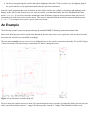
Then the macro transfer was run twice in a row, adding the line-to-line transfer structures to the nodes 423 and 454. Figure
3 shows the details of the line itinerary around node 423 before running the macro.
Figure 3: Line itineraries at transfer node 423.
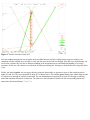
Figure 4 shows the transfer structure at node 445 generated with the macro. In order to graphically display the structure, the
macro was called with the option to ``stagger'' the dummy nodes, instead of ``hiding'' them behind the transfer node.
Figure 4: Transfer structure at node 423.
Next the standard assignment was run again on the modified network and the resulting transit segment volumes were
compared with the original ones, in order to verify that the route choice had not changed. Note that very small changes can
occur in the volumes; they are due to different rounding in the assignment process and different handling of ex-aequo
situations. In this case, the volumes were identical for all practical purposes, the largest volume difference being only about
1 trip.
Finally, the macro transfer was run again, this time using the functionality to generate a report of the transfer matrix at
nodes 423 and 454. The report obtained for node 423 is shown below. The column egress denotes trips which alight at node
423 and leave it through an auxiliary transit link. The row access denotes trips that get to node 423 through an auxiliary
transit link and then embark on a transit line. The other rows and columns are labels with the corresponding transit line
name and a direction indicator (">" or "<").
Conclusions
We have shown that the computation of consistent line-to-line transfer matrices is theoretically possible, and also
practically feasible, with the standard EMME/2 software release.
The macro we developed for this purpose has been written to be as independent of the specific application as possible. In
specific contexts, however, it is possible to adapt the same ideas to particular project requirement. Instead of computing
transfer matrices on the level of individual transit segments, it would e.g. be possible to compute aggregate transfer matrices
by line, link or mode groups. Of course the more aggregate the resulting transfer matrices are, the smaller the required
amount of computing resources.
The basic idea of adding this kind of additional structure at transfer points can also be exploited for other purposes than just
the computation of detailed transfer information. Since the various types of transfers can now be channeled to different
nodes, these can also be defined to have different characteristics, such as node dependent boarding times and wait factors.
This could be very useful to build more detailed assignment models, by taking into account transfer specific fare rules (node
specific boarding times) and timed transfers (node specific wait factors).
References
Aho, Kernighan and Weinberger (1988), The AWK Programming Language. Addison-Wesley Publishing Company.
INRO Consultants Inc. (1991), EMME/2 User's Manual, Release 5.0.
INRO Consultants Inc. (1992), EMME/2 Release Notes, Beta Release 5+.
Spiess and Florian (1989), Optimal Strategies: A New Assignment Model for Transit Networks. Transportation Research B,
Vol. 32B, No. 2. pp83-102.
Back to EMME/2 Support Center Homepage
Heinz Spiess, EMME/2 Support Center
Wed Mar 13 11:29:35 MET 1996