1
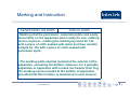
Key Comparison of Safety Requirements in
Europe, North America and Australia
for Electronic Products
Mr. K.F. Siu
15 April, 2010
www.intertek.com
1
Presentation Agenda
Standards For Audio/Video Product
Europe
•
EN 60065
U.S.A.
•
ANSI/UL 60065
Australia
•
AS/NZS 60065
(Refer to IEC 60065)
www.intertek.com
2
Principles of Safety
The application of the standard is intended to
prevent injury or damage due to the following
hazards:
•
•
•
•
•
•
Electric shock
Excessive temperatures
Radiation
Implosion
Mechanical hazards
Fire hazards
www.intertek.com
3
Scope
In addition to cover household use Audio/Video
product, commercial apparatus (apparatus for use
in trades, professions or industries and which is
not intended for sale to the general public) and
professional apparatus (video and audio
apparatus operated and maintained by trained
personnel under conditions of controlled access)
are covered by ANSI/UL60065 also.
www.intertek.com
4
Marking and Instruction
AS/NZS 60065, EN 60065
ANSI/UL 60065
-Marking shall be permanent, comprehensible and easily
discernible on the apparatus when ready for use; rubbing
test is required – rubbing the marking by hand for 15s
with a piece of cloth soaked with water and then another
sample for 15s with a piece of cloth soaked with
petroleum spirit.
-The marking plate shall be located at the exterior of the
apparatus, excluding the bottom. However, for a portable
apparatus or apparatus with a mass not heavier than 7kg,
the marking can be located at the bottom of apparatus
provided that this location is mentioned in user manual.
www.intertek.com
5
Marking and Instruction
a. Trade name or trade mark.
b. Model number
c. Class II symbol,
d. Nature of supply,
, if applicable
and / or
e. Rated supply voltage (e.g. AC230V, AC120-240V or AC110/230V )
f. Rated mains frequency, (e.g. 50Hz, 50-60Hz, 50/60Hz )
g. Rated current/Power consumption which can be supplied by the sample for
general use. (For AS/NZS 60065 and EN 60065, The information can be
shown in user manual as alternative)
i. RATED CURRENT / POWER CONSUMPTION
www.intertek.com
6
Marking and Instruction
The following items are in additional for standard ANSI/UL60065:
•
Date code - code of manufacture and shall have a minimum 10 year
repetition cycle.
•
A distinctive identification - when the same apparatus is produced at
more than one factory (may be our control no.)
•
Graphic symbols and supplemental marking -
“CAUTION – RISK OF ELECTRIC SHOCK – DO NOT OPEN”
www.intertek.com
7
Marking and Instruction
AS/NZS 60065, EN 60065
ANSI/UL 60065
the symbol can be used in circuit diagrams or put
adjacent to the relevant component, but not on
components.
Not required
The instruction shall include
an illustration of the
graphical symbols and an
explanation of their meaning
of safety related graphical
symbols used.
Not required
Important Safety Instruction
shall be included where
applicable. (items 1-14)
www.intertek.com
8
Marking and Instruction
AS/NZS60065, EN 60065
ANSI/UL 60065
“The apparatus shall not
be exposed to dripping and
splashing and that no
objects filled with liquids,
such as vases, shall be
placed on the apparatus.”
shall be added in the
instruction for use.
”WARNING – To reduce the
risk of fire or electric shock,
do not expose this
apparatus to rain or
moisture.” shall be used
instead
Some safety statements
Not required
are recommended to add in
instruction manual where
applicable
www.intertek.com
9
Hazardous Radiations
Ionizing radiation
AS/NZS60065, EN 60065
ANSI/UL 60065
Conduct the following
measurement under normal and
fault conditions according to
test method in the standard:
Checked with the
requirements in the United
States Code of Federal
Regulations, Title 21, Chapter
subchapterJ, Sections
- all adjusted controls are set to 1,
1010.2, 1010.3 and 1020.10
give maximum radiations
maintaining for 1 hour
- measure the exposure rate at
a distance of 5cm from any
point of outer surface
- the exposure rate shall not
exceed 36pA/kg
www.intertek.com
10
Hazardous Radiations
Laser radiation
AS/NZS 60065, EN 60065
- Should refer to standard
IEC60825-1:1993+A1+A2
- Laser system incorporated
inside the apparatus should
within the limit of class 1 under
normal operation; class 3R (for
λ out of 400-700nm) OR 5 times
the limit of class 1 (for λ within
400-700nm) under fault
condition
ANSI/UL 60065
Should be classified and
labeled in accordance with the
United States Code of Federal
Regulations, Title 21, Chapter
1, subchapter J, Sections
1010.2, 1010.3,1040.10 and
1040.11
- Further measurement on the
laser radiation will be required if
above item failed
www.intertek.com
11
Heating under Normal and Fault Conditions
Temperature rise limit of winding wires
AS/NZS 60065, EN 60065
Based on the type of its
insulated material
www.intertek.com
ANSI/UL 60065
Based on its insulation
class
12
Heating under Normal and Fault Conditions
Different requirements on fault condition
AS/NZS 60065, EN 60065
If the temperature is limited
by fuse-link, additional test
shall be required in relation
to the characteristic of the
fuse-link and the current
passing through it under
relevant fault condition
www.intertek.com
ANSI/UL 60065
No such consideration on
standard ANSI/UL 60065
13
Electrical Test
Leakage current measurement
AS/NZS 60065, EN 60065
touch current measured in
accordance with IEC60990, with
the measuring network as shown
below
While the limit are AC: U1 <
35Vpeak and U2 < 0.35Vpeak and
DC: U1 < 1.0V
www.intertek.com
ANSI/UL 60065
touch current carried out in
accordance with UL101, with the
measuring network as shown below
While the measured value shall not
exceed 0.5MIU
14
Electrical Test
Openings
AS/NZS 60065, EN 60065
ANSI/UL 60065
Jointed finger probe B of IEC61032
is used to determine
hazardous live parts
through opening,
including bottom
enclosure
Figure 14 is used
instead
Small finger probes
18 and 19 is used if
the apparatus is
intended to be
accessed by
children
This requirement is
deleted.
www.intertek.com
15
Electrical Test
Insulation requirement – Surge Test
AS/NZS 60065, EN 60065
ANSI/UL 60065
For class II apparatus, the insulation between:
- Terminals for the connection of antenna and mains
supply terminals and between
- mains supply terminals and any other terminals in case
of apparatus providing supply voltages to other apparatus
with antenna terminals
should be subjected to 50 discharges at a maximum rate
of 12/min, from a 1nF capacitor charged to 10kVdc in a
test circuit.
www.intertek.com
16
Electrical Test
Insulation requirement
Humidity treatment and insulation resistance
AS/NZS 60065, EN 60065
ANSI/UL 60065
The condition for humidity treatment and requirement of
insulation resistance are exactly identical between these
two standards.
Temperature: 28-30°C
Humidity: 90-95%
www.intertek.com
17
Electrical Test
Insulation requirement – Dielectric strength test
AS/NZS 60065, EN 60065
The test voltage for Basic,
Supplementary and
Reinforced Insulation
should refer to curve A and
B of figure 7 only.
ANSI/UL 60065
For the apparatus with mains
voltage in the range of 105130Vrms, the test voltage is
1414Vpeak for Basic and
Supplementary Insulation and
2828Vpeak for Reinforced
Insulation.
The test voltage for other mains
voltage should refer to curve A
and B of figure 7.
www.intertek.com
18
Mechanical Test
Bump test
AS/NZS 60065, EN 60065
ANSI/UL 60065
Test criteria: Apparatus with mass exceeding 7kg
Test method: Placed the apparatus on a horizontal support
of wood and allowed to fall 50 times from a height of 5cm
onto the wood
Compliance: Apparatus shall show no damage in the sense
of standard
www.intertek.com
19
Mechanical Test
Vibration test
AS/NZS 60065, EN 60065
ANSI/UL 60065
Test criteria: Transportable apparatus intended to be used for
audio amplification of musical instruments, portable apparatus and
apparatus having a metal enclosure.
Test method: Subjected to a vibration endurance conditioning by
sweeping according to the following condition in vertical direction:
-Duration: 30min;
-Amplitude: 0.35mm;
-Frequency range: 10Hz … 55Hz … 10Hz
-Sweep rate: approximately 1 octave/min
Compliance: Apparatus shall show no damage in the sense of
standard
www.intertek.com
20
Mechanical Test
Impact test – Impact hammer
AS/NZS 60065, EN 60065
- Subjected to three
blows from a springoperated impact hammer
to every point of the
exterior of the apparatus
ANSI/UL 60065
Not require for standard
ANSI/UL 60065
- used kinetic energy:
0.5J
- Shall comply with
dielectric strength test,
show no damage in the
sense of standard and
live parts shall not
become accessible
www.intertek.com
21
Mechanical Test
Impact test – Ball impact test
AS/NZS 60065, EN 60065
ANSI/UL 60065
Test criteria: The area of enclosure that protect
hazardous live parts
Test method: Single impact caused by a solid and
smooth steel ball of 50mm diameter and 500g mass to
fall freely from rest through a vertical distance in a
direction perpendicular to the surface of the enclosure.
Compliance: Shall comply with dielectric strength test,
show no damage in the sense of standard and live
parts shall not become accessible
www.intertek.com
22
Mechanical Test
Drop test
AS/NZS 60065, EN 60065
ANSI/UL 60065
Test criteria: Portable apparatus having a mass of 7kg or
less
Test method: A complete sample is subjected to 3 impacts
that result from being dropped through a distance of 1m
onto a horizontal surface.
Compliance: Shall comply with dielectric strength test, live
parts shall not become accessible, insulating barriers not be
damaged and creepage and clearance shall not be reduced
www.intertek.com
23
Mechanical Test
Stress relief test
AS/NZS 60065, EN 60065
ANSI/UL 60065
Test criteria: Apparatus with moulded enclosure of formed
by thermoplastic materials.
Test method: Placed the apparatus into a circulating air
oven to a temperature 10K higher than the max.
temperature observed on the enclosure during normal
temperature test but not less than 700C for a period of 7
hours, then permitted to cool to room temperature.
Compliance: Hazardous live parts shall not become
accessible.
www.intertek.com
24
Mechanical Test
Handle strength test
AS/NZS 60065, EN 60065
Not required for AS/NZS
60065 or EN 60065
ANSI/UL 60065
The weight of apparatus plus a
weight that exerts a force of
three time the weight of the
apparatus is to be uniformly
applied over a 75mm width at
the centre of the handle.
The handle or that portion of the
enclosure shall not break or
crack and the handle shall not
detach.
www.intertek.com
25
Mechanical Test
Telescoping or rod antennas
AS/NZS 60065, EN 60065
ANSI/UL 60065
- A telescoping or rod antenna shall be provided with
a minimum 6mm diameter button or ball on the end.
- 20N force shall be subjected at the end piece of the
antenna along its major axis for a period of 1 min.
- If the end piece of the antenna is attached by screw
threads, a loosening torque is to be applied to that
end piece of 5 samples.
www.intertek.com
26
Mechanical Test
Wall or ceiling mounting means
AS/NZS 60065, EN 60065
ANSI/UL 60065
- The apparatus is mounted in accordance with the manufacturer’s
instructions.
- A force in addition to the weight of the apparatus is applied
downwards through the geometric center of the apparatus for 1
min.
- The additional force shall be equal to 3 times the weight of the
apparatus but not less than 50N.
- The apparatus and its mounting means shall remain secure
during the test.
www.intertek.com
27
Mechanical Test
Stability and mechanical hazards
AS/NZS 60065, EN 60065
ANSI/UL 60065
Apparatus having a mass of 7kg or more shall be subjected to
the following tests and shall not overturn.
- Apparatus placed on a 100 inclined plate to horizontal and
then rotated slowly through an angle of 3600
- Apparatus placed on a non-skid surface with angle < 10 to
horizontal and a force 100N applied vertically downwards
www.intertek.com
28
Component standard for power supply and
transformer
AS/NZS 60065, EN 60065
No such considerations in
standard AS/NZS 60065 and
EN 60065
www.intertek.com
ANSI/UL 60065
Component power supplies
and their power transformers
complying with the
constructions and test
requirements of standard UL
1310, UL 1950 3rd Edition, UL
60950 or UL60950-1 are
considered to fulfill the
relevant test requirement.
29
Evaluations on Critical Components
AS/NZS 60065, EN 60065
ANSI/UL 60065
Components should
complied with test method
mentioned in standard
and/or complied with
relevant IEC/ EN/ AS/ NZS
standard for component.
Components should
complied with test method
mentioned in standard and/or
complied with relevant UL
standard for component.
www.intertek.com
30
Evaluations on Critical Components
Mains supply flexible cord
AS/NZS 60065, EN 60065
ANSI/UL 60065
- The color for wires used
- The color for wires used for
for protective earthing
connections should be
GREEN/YELLOW
protective earthing
connections should be GREEN
or GREEN/YELLOW
www.intertek.com
31
Flammability Requirement
PCB
EN 60065/ as/NZS 60065
ANSI/UL 60065
- should be V-1 or better for
- should be V-1 or better for
PCB with power > 15W
operating at a voltage
exceeding > 50V and ≤
400Vpeak a.c. or d.c. under
normal operating condition
PCB with power > 15W OR
operating at a voltage >
50Vpeak a.c. or d.c. under
normal operating condition
- should be V-0 for PCB with power > 15W operating at a
voltage > 400Vpeak a.c. or d.c. under normal operating
condition
www.intertek.com
32
Flammability Requirement
Distance from a potential ignition source
www.intertek.com
33
Flammability Requirement
Thermo-plastic materials – AS/NZS 60065
For apparatus containing voltage not exceeding 4kV:
Open-circuit
voltage of
Potential
Ignition Source
(PIS) Vpeak a.c.
or d.c.
Min. distance Flammability
from PIS to
category of the
thermo-plastic components
materials
Down- Upwards wards
Min. distance
from PIS to
non-metallic
barrier /
flammability
category of
barrier
> 50 and ≤ 400
13mm 50mm
V-1
V-1
> 400 and ≤
4000
13mm 50mm
V-1
5mm / V-1
Wood and wood-based material with a thickness of ≥ 6mm is fulfilled V-1
www.intertek.com
34
Flammability Requirement
Thermo-plastic materials – EN 60065
For apparatus containing voltage not exceeding 4kV:
Open-circuit
voltage of
Potential
Ignition Source
(PIS) Vpeak a.c.
or d.c.
Min. distance Flammability
from PIS to
category of the
thermo-plastic components
materials
Down- Upwards wards
Min. distance
from PIS to
non-metallic
barrier /
flammability
category of
barrier
> 50 and ≤ 400
13mm 50mm
HB75
No
requirement
> 400 and ≤
4000
13mm 50mm
V-1
5mm / V-1
Wood and wood-based material with a thickness of ≥ 6mm is fulfilled V-1
www.intertek.com
35
Flammability Requirement
Thermo-plastic materials –ANSI/UL 60065
Parts
Flammability category
Grille covering material, cloth and
reticulated foam
Tablet
Internal barriers with voltage exceeding
4kVpeak
V-2, V-1, V-0, VTM-2, VTM-1,
VTM-0
Polymeric and fiber materials in contact
with potential ignition source circuit
V-2, V-1, V-0, HF-2, HF-1,
HF-0, VTM-2, VTM-1, VTM-0
Sound-deadening material in contact with V-2, V-1, V-0, HF-2, HF-1,
speaker connections capable of
HF-0
producing greater than 240W audio power
Polymeric and fiber materials used in
applications other than those specified
above
www.intertek.com
HB, V-2, V-1, V-0, HBF, HF-2,
HF-1, HF-0, VTM-2, VTM-1,
VTM-0
36
Resistance to candle flame ignition
AS/NZS 60065, EN 60065
A television set shall be so designed that the likelihood of ignition and
the spread of fire caused by a candle flame is reduced.
Wood and WOOD-BASED MATERIAL with a thickness of at least 6
mm is considered to fulfil the V-1requirement when applying CLC/TS
62441.
Compliance is checked according to CLC/TS 62441.
www.intertek.com
37
Resistance to candle flame ignition
www.intertek.com
38
Resistance to candle flame ignition
www.intertek.com
39
Resistance to candle flame ignition
www.intertek.com
40
Our Contacts
For further information, please contact:
Home Entertainment , Audio & Video
Mr Brian Chu
Mr Jeff Cheung
Direct line: +852 2173 8480
Direct line: +852 2173 8531
Mobile:
Mobile:
+852 5313 6846
+86 150 1253 6846
Email: [email protected]
www.intertek.com
+852 6883 6523
+86 150 0204 0788
Email: [email protected]
41
www.intertek.com
42