1
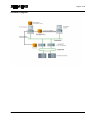
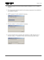
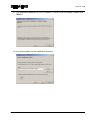
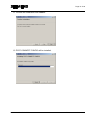
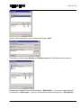
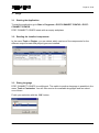
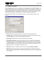
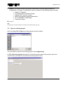
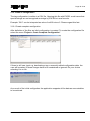
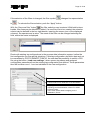
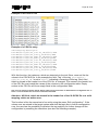
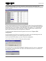
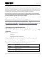
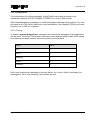
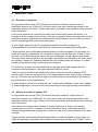
Page 1 of 62 PCS7-CONNECT CONFIG User manual V2.5.2 PCS7-CONNECT CONFIG Document version 2.5.2 Page 2 of 62 Version: V2.5.2 as of 24.04.2014 Contact: Phone (0621) 456-2303 Fax (0621) 456-3334 Email [email protected] Address Siemens AG GER I CS MTE MHM SD Dynamostr. 4 D - 68165 Mannheim Germany Subject to change without further notice 2000-2014 Siemens RC-DE I CS MTE MHM. All rights reserved. Dynamostr. 4, D-68165 Mannheim, Germany Registered trademarks: PI is a registered trademark of OSIsoft, Inc. IP.21 is a registered trademark of AspenTech Microsoft EXCEL, and Microsoft Windows XP or 7 are registered trademarks of Microsoft Corporation. PCS7-CONNECT CONFIG Document version 2.5.2 Page 3 of 62 Content 1. Overview ............................................................................................................................... 5 2. Installation and Uninstallation .............................................................................................. 10 2.1 Prerequisites ............................................................................................................ 10 2.2 Installation ................................................................................................................ 10 2.3 Licensing .................................................................................................................. 14 2.4 Uninstallation ........................................................................................................... 16 2.5 PCS7 OS Server access of the tool ......................................................................... 16 2.5.1 OPC DA server access ............................................................................................ 16 2.5.2 Microsoft SQL Server access ................................................................................... 20 3. Usage .................................................................................................................................. 21 3.1 Starting the Application ............................................................................................ 21 3.2 Reading the installed components ........................................................................... 21 3.3 Dialog language ....................................................................................................... 21 3.4 Creating a new project ............................................................................................. 22 3.5 Open an existing project .......................................................................................... 23 3.6 Project properties ..................................................................................................... 24 3.6.1 General .................................................................................................................... 25 3.6.2 Customize ................................................................................................................ 25 3.6.3 Scan cycles .............................................................................................................. 26 3.7 Project output settings ............................................................................................. 27 3.7.1 Project type „PI-Connect OPC+ Interface with option Archive Recovery” ................ 28 3.7.2 Project type „OSIsoft OPC Interface” ....................................................................... 30 3.7.3 Project type „BDIS Tag Interface“ ............................................................................ 31 3.7.4 Project type „Parameter“ .......................................................................................... 32 3.8 Compression parameters ......................................................................................... 34 3.9 Scan cycles .............................................................................................................. 36 3.10 Read structure tag definitions .................................................................................. 37 3.11 Filter definition .......................................................................................................... 38 3.12 Deleting a filter rule .................................................................................................. 40 3.13 Show invalid filters ................................................................................................... 40 3.14 Extended Information to a filter rule ......................................................................... 41 3.15 Filter export .............................................................................................................. 42 3.16 Filter import .............................................................................................................. 42 3.16.1 Import in XML format from other projects ................................................................. 43 3.16.2 Import of filters from the former “PCS7 Config tool” till version 7.3.0.1 .................... 43 3.17 Viewing the Logging information .............................................................................. 44 3.18 Create a configuration .............................................................................................. 45 3.18.1 Create complete configuration ................................................................................. 45 3.18.2 Create a Delta configuration .................................................................................... 51 3.18.3 Edit Configuration .................................................................................................... 52 3.19 Tagname Composer and measuring point type detection ........................................ 53 3.20 Help functionality ...................................................................................................... 56 3.20.1 Contents................................................................................................................... 56 3.20.2 Search...................................................................................................................... 56 3.20.3 About ....................................................................................................................... 56 3.21 Regular expressions ................................................................................................ 57 3.22 Command line mode (Non interactive mode) ........................................................... 57 3.23 Configuration............................................................................................................ 58 3.23.1 Tracing ..................................................................................................................... 58 PCS7-CONNECT CONFIG Document version 2.5.2 Page 4 of 62 4. Restrictions / Hints ............................................................................................................... 59 4.1 Equality of tag names .............................................................................................. 59 4.2 Moving a variable to another OS .............................................................................. 59 4.3 Change of the typical ............................................................................................... 60 4.4 Migration .................................................................................................................. 60 5. Revision history ................................................................................................................... 62 PCS7-CONNECT CONFIG Document version 2.5.2 Page 5 of 62 1. Overview PCS7-CONNECT CONFIG allows creating a tag configuration for several external process information systems in a comfortable way. To achieve the target tag configuration, the variables of a PCS7 OS server are read by predefined rules. The result of a configuration run of the PCS7-CONNECT CONFIG tool is a tag configuration in CSV format, which can be used to configure the target process data information system via their available tools (e.g. PI-SMT in OSI PI). Changes in the PCS7 project, can be detected via a Delta configuration run of PCS7-CONNECT CONFIG, which recognizes new, changed and deleted instances. Thus the tool synchronizes the PCS7 variables with the tag configuration of the target process data information system. The tool determines the existing structure types and their variables readable in the WinCC data manager. Out of this data the variables of the structure types for the tag configuration of the selected interface are detected For each parameter of a structure type the assigned data like engineering unit, describing text, compression, cycle etc. have to be defined. This happens very efficiently, when those data are readable out of other variables of the structure types, because they can be read for each instance directly out of the PCS7 project (e.g. for the structure type MEAS_MON the unit of the set point U is readable out of the parameter U#Units) If those data are not readable out of the variables of the structure type, they can be defined by a constant value for all instances of this structured type. PCS7-CONNECT CONFIG tool uses methods to read the configuration data out of the PCS7, which causes only a small load on the PCS7 OS servers. PCS7-CONNECT CONFIG Document version 2.5.2 Page 6 of 62 Further features of PCS7-Connect Config: For each PCS7 Server(pair) one project is installed. It consists of the following data: o Filter (=Rule set for the structure type parameters to be read) with the assigned structure types and depending replacement tables for the reading cycle and the compression. o Connection parameters to PCS7 o Valid constants for all tags to be placed in certain columns in the output file (Area, PLC Scanner, Prefix for the PCS7 variable names) o Status of the last config run as a basic data set for a delta run. Special constellations like existing tag configurations done manually, which must be kept, are covered by the tool. An EXCEL import to load the existing configuration parameters is available and will be considered in any configuration run. An automatic run, which creates an initial configuration for one project, is possible. To launch the automatic run the tool is called with parameters in a scheduled task. If more than one project exist, you have to install for every project a scheduled task. For each filter entity (= set of rules for one parameter, which has to be read) it is possible to define a Tagname Composer to built the tagname. The functionality is near to that of the Tagname Replacer of older tool versions, which was defined global for all Tags. The current Tagname Composer can be defined per filter entity. With the help of the Composer a PCS7 variable can be validated, split, concatenated and completed by constant strings. The user is responsible for the uniqueness of the built Tag names. Tag names, which are not unique, can be edited in the provided tool editor. The changes were set permanent and are used in future tool runs. During the run of the tool it is possible that OPC reading errors appear (e.g. range of measurement not readable, because measuring point is interrupted. Also such errors can be corrected by using the editor of the tool. The changes were set permanent and are used in future tool runs. The abbreviation of the Tag name to a specific maximum length has to be done by the Tagname Composer or by an abbreviation in the tool editor. If tags exist with the same tag name, which are not corrected, will be exported with error message or will be not exported depending on the project type. In an editor, provided by the tool, it is possible to edit any parameter before the export starts. The inserted values are stored and used in the following runs. The editor can only be used in an interactive mode. In the automatic mode the changes, which were done in the editor, are considered. A rule defined in the filter is always valid for all instances of a structiure type. A defined filter can be exported from a project to a XML file at any time. Assigned to the filter, also the tables for the reading cycle and the compression, which depend on the structure type, were exported. An exported filter can be imported in an other, existing project. PCS7-CONNECT CONFIG Document version 2.5.2 Page 7 of 62 A rule defined in the filter is always valid for all instances of a structiure type. It is possible to migrate the filter data out of the „PCS7 Configuration tool“, which is a former version of the current tool. For each filter entity it is possible to define a condition, which will be interpreted at run time. The result is bool (true/false). In case of a false value the tag will not be part of the generated tag configuration. Function „Parameter Enabled" For each filter entity 2 parameters or 1 parameter and 1 constant value can be defined. These will be compared by the operators „=“, „<“ und „>“ and lead to a binary result True/False. If the result is False, the tag will not be built. Example: A structure type has 4 alarm limits (HH, H, LL, L), which shall be archived in the target system, if the structure type uses these alarms. If not, the alarm limits in the DCS are very often configured outside the measuring range. The HH alarm limit value is then above the upper measuring range. Comparing the limit value with the measuring range (both values are readable values out of the PCS7 OS server at runtime) the tool decides if a value has to be archived or not. Possible negative effects using „Parameter Enabled“: If the alarm function of a structure type is not switched on or off by configuration, but during the runtime by manual input, each following run of the PCS7-CONNECT CONFIG tool will create new tags in case of alarm activating and will create tags to be deleted in case of alarm deactivating. If this happens very often by operator handling, it is for sure undesired. If this happens only one time during the configuration, it will be no issue. Function „Indexing" Once defining the project, the indexing of the typicals can be selected. Due to that the instance number für each typical beginning with one will be appended to the name of the typical type. Additionally the names of the instance and the parameter can be replaced by plant specific definitions/names. Example The PCS7 parameter name „F4711/CTRL-5.PV_IN“ will be transfered to „F4711/REG_1.PV“, where „REG_“ is the replacement for the instance name „CTRL-5“, “1” is the instance number and „PV“ is the replacement of the parameter name „PV_IN“. PCS7-CONNECT CONFIG Document version 2.5.2 Page 8 of 62 Licensing: One license is required for each interface machine. With this license you can read the configuration out of one PCS7 server pair. Consists a DCS system out of more than one PCS7 OS server pair, one additional license is needed for each additional server pair. Not redundant PCS7 OS servers as well as PCS7 OS single stations or redundant pairs of a PCS7 OS station will be handled from the PCS7-CONNECT CONFIG point of view like a redundant PCS7 OS server pair. PCS7-CONNECT CONFIG is available in 4 variants, which all use PCS7 as a source system and differ concerning the target process data information system (named as target system in the following). SIMATIC IT Historian for the target system Simatic IT Historian von Siemens PI-CONNECT OPC+ Interface for the target system PI of OSIsoft . IP.21-CONNECT CONFIG for the target system IP.21 of AspenTech BDIS Configuration with a target system independent output format OSIsoft OPC Interface for the target system PI of OSIsoft Parameter Output with a neutral output format (e.g. for controller optimizations, ..) In preparation Typically a PCS7 project consists of multiple instances of modules. Each module (e.g. CTRL_PID = PID control) has type specific parameters (e.g. PV_IN = controller process value input). The modules are realized in WinCC as so called structure tags. PCS7-CONNECT CONFIG reads via the OPC Data Access interface and optionally adds via data base access all existing structure tags, which have the parameter „#blocktype“. For these structure tags all parameters, which are available in the PCS7 servers tag management, are investigated. In addition all instances of the structure tags are read. This project structure is presented to the user in a comfortable user interface. In this surface definitions of a filter are done. The filter defines which parameters of a structure tag shall be transmitted to the external archiving system and which parameters of a structure tag hold additional information like range of measurement, engineering units and comments. If supported by the external archiving system additional attributes like compression and scan frequency can be defined. A rule defined in this way is valid for all instances of a structure tag. A new filter line is needed to read another parameter of the same structure type. Example: If the process value input (PV_IN) and the operation mode (QMAN_OUT) of a PID control shall be read two rules have to be defined. If there are 120 instances of the PID control defined in the PCS7 project 240 archiving variables will result. PCS7-CONNECT CONFIG Document version 2.5.2 Page 9 of 62 Schematic diagram: PCS7-CONNECT CONFIG Document version 2.5.2 Page 10 of 62 2. Installation and Uninstallation 2.1 Prerequisites PCS7-CONNECT CONFIG needs PCS7 (Version V6 or newer) as a source system. Older versions on request. To create the full tag configuration the PCS7 system including the PLCs must be completely built up and accessible. Only those variables, which are mapped into the WinCC data manager, can be read. For installation of PCS7-CONNECT CONFIG your computer must fulfil the following preconditions: Operating System: Microsoft Windows XP (Service Pack 3) Microsoft Windows 7 Software: .NET-Framework 2.0 and Windows Installer 3.1. The .NET framework is a programming platform of Microsoft; the Windows Installer is needed to install programs delivered as MSI packages. If the .NET framework or the Windows Installer 3.1 does not already exist on your computer they will be installed during setup of PCS7-CONNECT CONFIG. OPC Core Components 3.0 („OPC Core Components Redistributable (x86).msi“) Hint:If your computer doesn’t have this OPC Core component installation, please install it from the delivery CD of PCS7CONNECT CONFIG. Hardware: Computer with minimum Pentium IV-Processor und at least 2 GB RAM. For the installation administrative rights are necessary. To use the tool normally main user rights are enough. 2.2 Installation For Installation of PCS7-CONNECT CONFIG do the following steps: 1. Insert the PCS7-CONNECT CONFIG CD-ROM into the CD-ROM drive. 2. Please read the file “README.TXT“, if it exists. It may contain urgent actual installation hints. 3. Start the program „SETUP_EN.EXE” from the CD-ROM. PCS7-CONNECT CONFIG Document version 2.5.2 Page 11 of 62 4. The setup program will lead you through complete installation of PCS7-CONNECT CONFIG. 5. The setup program primarily checks for all necessary components to be available on the installation computer. 6. .NET Framework 2.0 will be installed if necessary. 7. Windows Installer 3.1 will be installed if necessary. 8. A reboot of the PC may be necessary after installation of .NET framework 2.0 or Windows Installer 3.1. Installation will be continued automatically after reboot. PCS7-CONNECT CONFIG Document version 2.5.2 Page 12 of 62 9. The installation assistant of PCS7-CONNECT CONFIG will be started. Please click "Next >" 10. You will be asked for the installation directory. PCS7-CONNECT CONFIG Document version 2.5.2 Page 13 of 62 11. Confirm the installation with "Next >" 12. PCS7-CONNECT CONFIG will be installed. PCS7-CONNECT CONFIG Document version 2.5.2 Page 14 of 62 13. Finish the installation by clicking the "Close" button of the installation wizard. Hint:For a correct installation on Windows XP the user must have write access to the registry. 2.3 Licensing Please start the program CreateUMI_PCS7ConnectConfig.exe contained on the installation CD on the PC where PCS7-CONNECT CONFIG shall be licensed. Please select the PCS7 OS servers, you want to connect. To do this, select the line with the server name and then click into the check box. PCS7-CONNECT CONFIG Document version 2.5.2 Page 15 of 62 If you want to connect a server, which is not listed, you can insert the name at the bottom of the form and select the “Add” button. Please keep in mind, that this server must be accessible. Otherwise the following message will be shown. To create the needed information push the “Create UMI” button. After that the file UMI_PCS7ConnectConfig.dat is created and shown in the Windows browser, after the success message is acknowledged by the user. PCS7-CONNECT CONFIG Document version 2.5.2 Page 16 of 62 Please send this file to [email protected] . Thereafter you will receive the according license file. The license consists of 2 files UMIL.TXT and UMIL.DAT. Please copy these files to the installation directory of PCS7-CONNECT CONFIG. Without a license you can use the tool for test issues with the restriction of 5 instances. 2.4 Uninstallation To remove the software do the following steps: In Start > Settings > Control Panel > Add and Remove Software search and mark the entry PCS7-CONNECT CONFIG. Click the Button “Remove”. The software will be removed automatically. 2.5 PCS7 OS Server access of the tool To get the configuration the tool connects the PCS7 OS server. The access is done via the following interfaces: OPC DA server MS SQL server 2.5.1 OPC DA server access An OPC server is a COM server. COM is an object model of to develop divided applications. The access is done via Operating System bibliotheca. Using the extension of COM called DCOM (Distributed COM) the access is also possible from to other PCs. DCOM is only PCS7-CONNECT CONFIG Document version 2.5.2 Page 17 of 62 possible using authenticated access between the PCs. Using a firewall you have to keep in mind, that DCOM uses a free area of ports. It is necessary that the users which are logged in on the PCs provide access rights to each other. In addition the client PC (machine where PCS7-CONNECT CONFIG is installed) and the Server PC (PCS7 System) must either be member of the same domain or Workgroup. Hint: In a working group the user is on every machine the same if user name and password are the same. Inside a domain both hosts must be part of the domain and can use the same domain user name. In any case the machine where PCS7-CONNECT CONFIG and the one where the PCS7 OS server is running must be part of the same domain or working group. Normally the tool will be installed on an interface machine with connection to PCS7 (e.g. with OpenPCS7 or WinCC installation). In this case you do not need any DCOM settings, which are described in the following. For DCOM settings login as administrator. Start the Management Tool Component Services (COM+) via Start > Run… > dcomcnfg.exe The Management Tool will be started. Navigate in the tree to Console Root – Component Services – Computer – My Computer PCS7-CONNECT CONFIG Document version 2.5.2 Page 18 of 62 Open the dialog “My Computer Properties“ by right clicking on context menu of “My Computer” and select “Properties”. Jump in this dialog to the folder “Default Properties“ and make sure that DCOM is activated. Switch to the Folder „COM Security”. Edit and check the settings for “Access Permissions” and “Launch and Activation Permission”. Press the button “Edit Limits…” in the Access Permissions. The actual access permissions will be displayed. PCS7-CONNECT CONFIG Document version 2.5.2 Page 19 of 62 Add the Administrators group by clicking the button “Add”. Thereafter activate Local Access and Remote Access for the Administrators group. Repeat these Steps for Access Permissions - Edit Default…, for Launch and Activation Permissions – Edit Limits… and for Launch and Activation Permissions – Edit Default... PCS7-CONNECT CONFIG Document version 2.5.2 Page 20 of 62 Confirm the changes and leave the dialog „My Computer Properties” by clicking the “OK” Button and closing the Component Management For further configuration possibilities please refer to the OPC foundation and the help function of the operation system.Please keep in mind, that the OPC server may not use the standard configuration. In this case please check also the DCOM settings of the OPC server as follows: Please start Start > Run… > dcomcnfg.exe Check the settings in Console root – Component Services - Computer – My Computer – DCOM Config. Only necessary for Windows XP: Make sure the “simple file sharing“ in the folder options of the Windows explorer is deactivated. To check this, start the Windows Explorer and choose Tools > Folder Options > View > Advanced settings 2.5.2 Microsoft SQL Server access The following prerequisites are needed fort he access to the MS SQL Server of the PCS7 OS servers: Standard SQL Server port 1433 (UPD/TCP) is not blocked by the firewall. The user the tool is running has to have login rights to the SQL Server. The right to login is given, if the tool runs with the same user as the PCS7 OS server is logged in. If the users are different, you have to check, that the user, under which the tool runs, has login rights to the SQL server. PCS7-CONNECT CONFIG Document version 2.5.2 Page 21 of 62 3. Usage 3.1 Starting the Application To start the application go to Start > Programs > PCS7-CONNECT CONFIG > PCS7CONNECT CONFIG PCS7-CONNECT CONFIG starts with an empty workplace. 3.2 Reading the installed components In the menu Tools > Plugins, you can detect which versions of the components for the different output formats and project types are installed. 3.3 Dialog language PCS7-CONNECT CONFIG is multilingual. The switch to another language is possible in the menu Tools > Customize. You will then receive the available languages and can select one of them. Finish your selection with the „OK“ button. PCS7-CONNECT CONFIG Document version 2.5.2 Page 22 of 62 3.4 Creating a new project After starting the application an new project may be created by choosing File > New… In a project all data like e.g. connection parameters to the PCS7 source system, or filter data to create the tag configuration of one source system (also for a redundant PCS7 server pair) are managed and stored. A project will be created once and can be used multiple times to create a tag configuration. Also changes e.g. of the filter settings are possible. In the dialog "New Project" the following information must be provided to define a new project: Name: Name of the project and path, to be created to store the project data Location: Name of the directory where the project file and the data are stored. Via the button “Browse” the location may be selected and created. Project type: Defines the source system with the system version. Use Instance Indexing: If this option is selected, an index is added to the target tag name starting with „01“, if the name appears more then one time out of the rules of the TagNameComposer. Once the index is created, the index and the names, which were created are kept alive for the instances, even when the instances are deleted in PCS7. Host: Node name or IP address of the PCS7 server. OPC Server: Name or ProgID of the OPC Server (Normally OPCServer.WinCC. SQL Server: Determines whether the login to the SQL Server of the PCS7 system is done via Windows authentication or SQL-Server authentication with user and password to be inserted. PCS7-CONNECT CONFIG Document version 2.5.2 Page 23 of 62 Output: The output format of the project determines for which target system the configuration is created. Configuration may be created for the following output formats: Simatic IT Historian PI-Connect OPC+ Interface Output OSIsoft OPC Interface Output BDIS Tag Interface (target independent) IP.21-CONNECT CONFIG Parameter Output In preparation. Hint: Depending on the output format the contents of this working area may vary. 3.5 Open an existing project With the dialog File > Open an existing project may be loaded. You are asked to select the according project file configtool.cfg. In File > Recent projects alternatively to the dialog menu above the projects, which are used at least, are listed for activation by selecting one of them. PCS7-CONNECT CONFIG Document version 2.5.2 Page 24 of 62 3.6 Project properties After a new project has been created, the properties of this project should be set first using “Project > Properties”. The dialog "Properties" is shown. PCS7-CONNECT CONFIG Document version 2.5.2 Page 25 of 62 3.6.1 General In the register folder "General" you see a summary of the actual properties. Additional information about the project may be added in the input filed “Description“. 3.6.2 Customize The register folder "Customize" allows to add project wide settings. PCS7-CONNECT CONFIG Document version 2.5.2 Page 26 of 62 Using regular expressions (see also chapter 3.21 ”Regular expressions”) in the Default Tagname-Composer field may be defined how the tag name of the destination system is created out of the OPC variable name. This pattern and the replacement will be copied to the columns „Pattern“ and „Replacement“ when a filter is defined. The button „Test“ allows the user to check, if the regular expression delivers the right result. Hint: For further information about Tagname Composer and Measuring Point Type Detection please refer to chapter . Example for the creation of a tag name out of the source tag name: Source tag name:Teilanlage9/T4711/R.PV_IN Regular expression: .*/([A-Z]{1,2}[0-9]{3,4})/(.*)\.(.*) Replacement: $1-REG-$3 Result tag name:T4711-REG-PV_IN In the field Measuring Point Type Detection is defined how the measuring point type is calculated out of the OPC variable name, also using regular expressions. The button „Test“ allows the user to check, if the regular expression delivers the right result. Example for a measurement type recognition: Source tag name:Teilanlage9/T4711/R.PV_IN Regular expression: .*/([A-Z]{1,2})[0-9]{3,4}/.*\..* Replacement: $1 Result type: T The field Scan Cycles is used to define the scan cycles and the assignment to the project specific WinCC scan cycles. Scan cycles are defined in seconds. In field Engineering Unit you can define whether a translation table has to be used for the engineering units. Using the Advanced Process Library of PCS7 (V7.1 or later) the engineering units for an analogue value are no more a string but an ID. Via the ID the according engineering unit is found in a mapping table. In the field “Engineering Unit” you select that the mapping shall be used. The Mapping table may be shown with the button “Show Mapping”. 3.6.3 Scan cycles These settings are only displayed, if the selected output format supports scan cycles. Here you can see the standard WinCC scan cycles and define additional cycles, which shall be used. Hint: This function is not available in the output format “Parameter Output” PCS7-CONNECT CONFIG Document version 2.5.2 Page 27 of 62 3.7 Project output settings In the menu “Project > Output Settings…” the parameters for the output, that means standard values for the creation of the tag configuration of the selected project type, may be set. The available parameters depend on the project type. If tags rise with the same name during the configuration run, which are not corrected by the user, or are there reading errors for one tag, which are not corrected by the user, the data for the output format „BDIS Tag Interface“ is exported with error message. For all the other output formats these data sets will be ignored and not created. PCS7-CONNECT CONFIG Document version 2.5.2 Page 28 of 62 3.7.1 Project type „PI-Connect OPC+ Interface with option Archive Recovery” For the project type “PI-Connect OPC+ Interface” additional constant attributes are available, which should be set (e.g. access rights, PointSource etc.). These attributes are valid for all measuring points. For the configuration the following dialogue is used: For the following attributes of the configuration standard values may be defined: • • • • • • • • • • • • • • • • archiving compmax compmin compressing DataAccess DataGroup DataOwner excmax excmin location1 location3 pointsource PtAccess PtGroup PtOwner Shutdown PCS7-CONNECT CONFIG Document version 2.5.2 Page 29 of 62 • • Step OPC Item Prefix A detailed description of the fields may be found in the OSIsoft PI System documentation resp. in the documentation of the Siemens „PI-Connect OPC+“ Interface. Select “Insert Keyword ItemID”, if you use the old Siemens OPC + interface, do not select, if PI-CONNECT OPC+ is in use. Select “WIS for the PI server”, if the user authentication of the target system is done via Windows accounts. If selected please insert the PI access strings for data and point security for the used accounts. With the parameter “Background Colour for User Changes” you have the possibility to define the background colour of user inputs done in the dialogues “Project > Create complete configuration” resp. “Project > Create Delta Configuration”. Choosing the „Archive Recovery aktivieren“ option, the tool will add the needed parameters for an Archive Recovery (OPC HDA) of the WinCC archives during the run to generate a configuration. To activate the „Export Bad Tags“ option in the „Error Handling“ section, all variables, which are read with error (e.g. because the AS systems are nit available and therefore no measuring span can be read), are not considered in the configuration. With the decimal separator you define the decimal sign for an export in a CSV file. PCS7-CONNECT CONFIG Document version 2.5.2 Page 30 of 62 3.7.2 Project type „OSIsoft OPC Interface” For the project type „OSIsoft OPC Interface” additional constant attributes are available, which should be set (e.g. access rights, PointSource etc.). These attributes are valid for all measuring points. For the configuration the following dialogue is used: For the following attributes of the configuration standard values may be defined: • archiving • compmax • compmin • compressing • DataAccess • DataGroup • DataOwner • excmax • excmin • location1 • location3 • pointsource • PtAccess • PtGroup • PtOwner • Shutdown • Step • OPC Item Prefix PCS7-CONNECT CONFIG Document version 2.5.2 Page 31 of 62 A detailed description of the fields may be found in the OSIsoft PI System documentation resp. in the documentation of the Siemens OPC+ Interface. Select “WIS for the PI server”, if the user authentication of the target system is done via Windows accounts. If selected please insert the PI access strings for data and point security for the used accounts. With the parameter “Background Colour for User Changes” you have the possibility to define the background colour of user inputs done in the dialogues “Project > Create complete configuration” resp. “Project > Create Delta Configuration”. To activate the „Export Bad Tags“ option in the „Error Handling“ section, all variables, which are read with error (e.g. because the AS systems are nit available and therefore no measuring span can be read), are not considered in the configuration. With the decimal separator you define the decimal sign for an export in a CSV file. 3.7.3 Project type „BDIS Tag Interface“ For the following attributes of the configuration standard values may be edited: PLS Selector (= PCS7 Variable name possibly concatenated with a server prefix) Area (= constant value for all Tags of the project) PLS Scanner (= constant value for all Tags of the project) Background color for user changes Decimal separator With the decimal separator you define this for the export in a CSV file. The output of the tool is in a CSV file format. Each BDIS tag is assigned to one row in the CSV file. Format 1 and Format 2 define the structure of the elements written in the output file. Format 1: Name (Tag name) PCS7-CONNECT CONFIG Document version 2.5.2 Page 32 of 62 OBJ_Type (PCS7 typical) Type (Data type: Analog, integer, binary or digital respectively digital sets) DIGITALSET (Name of the Digital set) PLS_SELECTOR (PCS7 variable name as shown in the WinCC Data manager) XA (Start of the measurement range) XE (End of the measurement range) ENGUNIT (engineering unit) DESCRIPTION (description out of PCS7) POINTSOURCE (Pointsource) PLS_SCANNER (Prefix for all tags of the project) EXDEV (Absolut compression parameter of the horizontal dead band) COMPDEV (Absolut compression parameter of the vertical dead band) SCAN (Scan cycle in milliseconds) ERROR (OK/Replacer Validation error / Tag name not unique) Format 2(near to the AspenTech IP.21 column structure): Name (Tag name) OBJ_Type (PCS7 typical) IP_TAG_TYPE (Data type, e.g. analog) IO_TAGNAME (Variable name in PCS7) IP_GRAPH_MINIMUM (Start of the measurement range) IP_GRAPH_MAXIMUM (End of the measurement range) IP_ENG_UNITS (Engineering unit) IP_DESCRIPTION (Description out of PCS7) IP_PLANT_AREA (Fix area name for all tags of the project) IO_HOST (Fix description out of the field PLS-Scanner) 3.7.4 Project type „Parameter“ For Parameter Output the data were created in a target independent format as a CSV file. In the output parameters the name of the output file and the separator for the fields inside the file may be assigned. The standard values are “parameter.csv” and “;”. The output of the tool is a file in CSV format. Each BDIS tag is assigned to one row in the CSV file. PCS7-CONNECT CONFIG Document version 2.5.2 Page 33 of 62 Output elements: Instance (Variable name in PCS7) Parameter (Parameter name of the typical) StructureTag (PCS7 typical) PointType Value (Value of the parameter) Error PCS7-CONNECT CONFIG Document version 2.5.2 Page 34 of 62 3.8 Compression parameters Choosing the menu Project > Compression Parameter the project specific compression settings, which may be advised to specific measurement types, can be set. For a new project a parameter set (high, low and standard) is predefined, which may be changed but not deleted. The compression parameters can be absolute or percentage values. A percentage value is always assigned to the measuring range of a variable (maximum minus minimum). Section “Tables” With the button “Add” in the section Tables a new table can be added. The button “Add” is active if a valid and not yet existing name is set in the field Name. By selecting a table from the list Tables, its entries are shown in the Section Parameters and may also be changed. With the button “Delete” an existing table may be deleted. The button is only activated if a user defined table is selected. The system tables high, low and standard can not be deleted. Section “Parameter” The button “Modify” allows modifying an existing entry. Actual settings for Exception and Compression may be entered in % of the range of measurement or in absolute values. With the button “Delete” an existing entry may be deleted. The number of entries for the compression parameters is not limited. Relation to the Standard Tagname Composer Each filter line holds a specific number of instances. If the names of the instances follow a construction rule and contain the measurement type, the application is able to extract this measurement type using regular expressions (refer to Project Settings, chapter 3.6.2) and use it for setting the compression and scan cycle depending on the measurement type. PCS7-CONNECT CONFIG Document version 2.5.2 Page 35 of 62 Example: Pressure Measurement start with a „P“, levels with „L“, flows with „F“, temperatures with „T“ etc.. In the project regular expressions and replacements for the tag name definition and recognition of the measurement type are assigned: Example for the creation of a tag name out of the source tag name: Source tag name:Teilanlage9/T4711/R.PV_IN Regular expression: .*/([A-Z]{1,2}[0-9]{3,4})/(.*)\.(.*) Replacement: $1-REG-$3 Result tag name:T4711-REG-PV_IN Example for measurement type recognition: Source tag name:Teilanlage9/T4711/R.PV_IN Regular expression: .*/([A-Z]{1,2})[0-9]{3,4}/.*\..* Replacement: $1 Result type: T In a project normally temperatures (changing slowly) are archived with other compression settings than pressures (changing fast). The possibility of using different compression settings is realized as follows: Examples: A replacement table "Messwert" is defined. Instances, which do not meet the list of identifiers ('*'), will be configured with the deadbands Exception=0.5% and Compression=1%. Instances with the measurement type “F”, will be configured with Exception=1% and Compression=2%. For the instance used in the example (TA1107/F4712/R.PV_IN) those compressing parameters would be used. PCS7-CONNECT CONFIG Document version 2.5.2 Page 36 of 62 Instances with the measurement type “G” will be configured wit the absolute values for Exception=0.5 und Compression=1. 3.9 Scan cycles With the menu “Project > Scan Cycle Definition” replacement tables may be defined. Hint: This function is not available in the output format “Parameter Output”. Section “Tables” With the button “Add” in the section Tables a new replacement table may be defined. The “Add” button is activated, if a valid and not yet existing table name is put in. The table name is definable and multiple replacement tables may be defined. Section “Parameter” The identifier represents here a substring of the name of the instances. Variables, whose name matches the substring, were configured with the assigned cycle. Each new table automatically has a parameter set for the identifier “*”. Instances which do not meet another identifier will be configured with this scan cycle. This identifier may be modified, but can not be deleted. PCS7-CONNECT CONFIG Document version 2.5.2 Page 37 of 62 3.10 Read structure tag definitions Before filter rules may be defined in a project primarily the structure type and parameter information from PCS7. In addition the instance must be determined. To do so, use the menu “Project > Read Structure Tag Definitions”. PCS7-CONNECT CONFIG reads the data via the OPC DA connection out of the PCS7 server. During this reading, additional resources on the PCS7 server are necessary. An Initial or Delta run should not be done during a PCS7 OS server synchronization or when the plant is in a critical state (Bulk messages, Shutdown of a redundant PCS7 server). PCS7-CONNECT CONFIG stores the read structure types, and provides them for the creation of the filter definitions (see also next chapter). PCS7-CONNECT CONFIG Document version 2.5.2 Page 38 of 62 3.11 Filter definition Definition of a filter rule is only possible after the structure information has been read out of PCS7. To define a new filter rule select the menu “Filter > New”. In the display a new filter line is shown: In the column “Structure Tag” first select a structure type in the drop down list. Thereafter the “Parameter” may be selected. PCS7-CONNECT CONFIG Document version 2.5.2 Page 39 of 62 In the columns “XA”, “XE”, “Eng unit” and “Description” the existing parameters may be chosen from the drop down lists or a constant value may be put in. In case of a constant value is put in all instances of this line get the same value. The settings for compressing are done in the two columns “Exception” and “Compression”. It is possible to put in a constant value (absolute or in per cent) or a link to a replacement table (refer to chapter 3.8). Exception is set for the compression via horizontal deadband and Compression for the vertical deadband compression (see also descriptions of the interface programs to the archiving system). The column “Point type” defines the data type (float or integer) in the archiving system. The data type „Digital“ needs the definition of the „Digital set“ field with a digital set of the target archive system. In the column “Scan cycle” the scan rate for the archiving may be chosen. The user may either select one of the WinCC Scan classes or a replacement table for the scan cycle. In the last case the scan class depends on the kind of measurement. Replacement tables are only listed when according tables are available (refer to chapter 3.9) The column “Use TagComposer” determines if a replacement of the tag name for the destination system shall be used. With the button “Edit TagComposer” the settings may be done. For details please refer to chapter . In the field „Enabled“ the user has the possibility to define a condition, which decides if a variable will be part of the tag configuration or not. There are no plausibility checks, that means, that wrong definitions or the use of not existing parameters could lead to wrong output data. Example: „(Alarm_Oben < MO_PVHR) AND (Alarm_Unten > 1.3)“ To define a condition the parameters themselves (see example) or constant values can be used. Constant values need the “.” as a separator for the post decimal position. As an operator „<“, „>“, „=“ and „<>“ are valid. Strings must be defined with inverted commas. For logical operations „AND“ and „OR“ are possible. Expressions can be structured by brackets. Hint for the use: To see all characters of the last field „Enabled“ it is necessary to use the scrollbar to go to the very right position and then to make a double click on the right border of this column “Enabled”. Hint: Each parameter of a structure tag which shall be archived in the external archiving system needs a single filter line. Hint: Changing the Structure Tag of filter rule (line) resets all other colums of this filter rule. Hint: Not for each Parameter a parameter exists for start of measurement end of measurement, engineering units and comment. All digital process values for example and some analogue values do not have parameters for start of PCS7-CONNECT CONFIG Document version 2.5.2 Page 40 of 62 measurement, end of measurement, engineering units. For those cases a constant value may be provided in the filter which is used for instances. For digital values we recommend to set the start of measurement value to “0” and the end of measurement value to “1“. Faulty filter rules will not be recognized by the creation of a configuration and are signed with a symbol. Moving the curser on the symbol, an error text will be shown. In this example project two filter rules for the same parameter "PV_IN" and the same Structure Tag ("PID_SC") are defined. Moreover the start of measurement XA in the second rule is higher than the end of Measurement XE. 3.12 Deleting a filter rule To delete a filter rule select the according line and chose the menu “Filter > Delete”. 3.13 Show invalid filters In the menu „Filter > Show Invalid…“ of the filter menu the user may get the set of filter entries, which are part of the project but deactivated. This happens if there is no instance reference of the PCS7 project to a defined structure tag in the filter. That means, that the structure tag does not exist e.g. because another library is used. With the “Delete” button the invalid filter entries can be deleted. PCS7-CONNECT CONFIG Document version 2.5.2 Page 41 of 62 3.14 Extended Information to a filter rule By marking a filter rule und choosing the menu “Filter > Info…” an overview of the parameters of the structure tag for which the filter was defined is shown and a list of the instances via menu “Instances”. PCS7-CONNECT CONFIG Document version 2.5.2 Page 42 of 62 3.15 Filter export A filter export normally is needed to copy the selected variable types from one project to the other or to prepare a migration of the PCS7-CONNECT CONFIG tool to a newer version. In this case the user does not need to insert again the filter sets. With the menu “Filter > Export” the filter rules of a project may be exported in XML-format. In the following dialog provide a filename for the data export and confirm the export with OK. Hint: Exported were filter rules, compressing parameters and scan cycles. 3.16 Filter import If a filter is imported, all filter lines are deleted and replaced by the imported filter rules. If the imported filter has relation to structure types, which do not exist in the current source system, the assigned filter rules where marked as “not valid”. These entries can then be visualized by using “Filter > Ungültige anzeigen…“. Additionally after the import the user will get a message. Please read first the structure types before you import the filters in order to enable the filter import to check the assignment of the current typicals. The filter import is started with the menu “Filter > Import…” PCS7-CONNECT CONFIG Document version 2.5.2 Page 43 of 62 3.16.1 Import in XML format from other projects Filters of the PCS7-CONNECT CONFIG tool will be exported in XML format and can be reimported again from XML format in order to take over filter entities from other connections or to make filters available again after an upgrade of the tool. To import filter rules in XML format make sure that the file type “*.xml” is selected. 3.16.2 Import of filters from the former “PCS7 Config tool” till version 7.3.0.1 In the former version a filter export was not possible. Nevertheless it is possible to read these filter sets directly from the database file and to migrate them. To import filter rules from a former PCS7 Config tool, make sure that the file type “*.mdb” is selected. PCS7-CONNECT CONFIG Document version 2.5.2 Page 44 of 62 Navigate to the output directory of the PCS7 CONFIG tool (former config tool) and select the file “Konfig.mdb”. In the following dialog you will see all projects of the PCS7 CONFIG tool. Select the project from which the filter rules shall be imported. Optional you also are able to import the compressing parameters and scan cycles. To do this the check boxes must to be selected. Otherwise the standard parameters for the compression and the scan cycles were moved to the project. The import procedure is completed with the “OK” button. 3.17 Viewing the Logging information During the activities in the PCS7-CONNECT CONFIG tool a Log file is written with the most important information. The information can be viewed in the tag “Log” in the area below the menu bar or via the menu View >Log. The tag Log exists if it is selected before in the menu View >Toolbar. There are information about the license and the selected project types etc. With the button “Folder” the user moves to the directory with the Log file and can then e.g. copy the file. PCS7-CONNECT CONFIG Document version 2.5.2 Page 45 of 62 3.18 Create a configuration The tag configuration is written in a CSV file. Opening this file with EXCEL could cause that special strings are not recognized as strings by EXCEL but as a formula. Example: “BI-2” can be interpreted as value of cell BI minus 2. Please regard this fact. 3.18.1 Create complete configuration After definition of the filter an initial configuration is created. To create the configuration file select the menu “Project > Create Complete Configuration”. If there is still user input e.g. deactivating a tag or manually edited configuration data, the user will be asked, if these changes have to be considered or ignored. Do your choice selecting Yes or No. As a result of the initial configuration the application supports all the data as new variables to be archived. PCS7-CONNECT CONFIG Document version 2.5.2 Page 46 of 62 The user has now the possibility to edit the configuration. Via the buttons all measured values can be selected or deselected. Via the check boxes beside the entries single parameters can be selected or deselected. Single values also can be changed manually. Values, changed by the user, will be displayed colored. To show and to recover the original value, select the field and use the right mouse click. Cells with error are shown with a symbol. The visualized entries may be filtered using the check boxes below. Using the filter „User edits“ all lines are shown, which were changed by the user. The filter “Errors” selects all lines with error. PCS7-CONNECT CONFIG Document version 2.5.2 Page 47 of 62 If the selection of the filters is changed, the filter symbol to changes his representation . To activate the filter selection, push the “Apply” button. With the “Save row filter” button , the filter selection may be stored. With both buttons beside, filter lines may be deleted or added. If a new filter has to be created, the selection criteria may be defined in the box right beside, inserting the source (one of the displayed columns), the operator and a value. The name of the filter can be changed selecting the field, where the name is displayed. Plants with existing tag configurations in the process data information system, before the first configuration run are special situations. If this tag configuration should be kept and not be overwritten by PCS7-CONNECT CONFIG, the user has the possibility to select a CSV file using the button „Load user settings“, where source tag names and assigned configuration parameters from the existing tag configuration are defined. These parameters then will be taken over 1:1 and not validated to the new configuration. Selection of a Excel’97- or CSV-File If it’s a Excel’97-File: Selection of the Worksheet Mapping between the source column (from the file importing) and the destination columns of PCS7Connect Config. There must exist at least a mapping for the destination „Souce“. PCS7-CONNECT CONFIG Document version 2.5.2 Page 48 of 62 Example of an Excel’97 file Example of a CSV file entry: OPCItem;Tag;Descriptor FSL-BS0001-Q001/PV_DIG.PV_IN;A0001;AAA FSL-BS0001-Q001/PV_DIG.Q_PV;A0002;BBB FSL-BS0001-T001/PV_ANA.PV_IN;A0003;AAA FSL-BS0001-T001/PV_ANA.Q_PV;A0004;BBB FSL-BS0002-Q001/PV_DIG.PV_IN;A0005;AAA FSL-BS0002-Q001/PV_DIG.Q_PV;A0006;BBB FSL-BS0002-T001/PV_ANA.PV_IN;A0007;AAA FSL-BS0002-T001/PV_ANA.Q_PV;A0008;BBB FSL-BS0003-Q001/PV_DIG.PV_IN;A0009;AAA FSL-BS0003-Q001/PV_DIG.Q_PV;A0010;BBB With this function, the instances, which are detected via the tool filters, were set like the values in the CSV/XLS file. In the example the field „Tag“ of the tag „FSL-BS0001Q001/PV_DIG.PV_IN “ is set to “A0001”, indicating a renaming of this tag. Each field, which is named in the header line of the CSV file, is changed. The names in the header line of the CSV file must match the names of the columns in the configuration table. Empty entries in the CSV file will force empty fields in the configuration table. Hint: You can specify a column named “Select” where the user activates or deactivates the configuration line. If there’s no such column then all rows are marked as activated. Attention: All fields, which are named in the header line of the XLS/CSV file or a valid mapping exists are written over. This function is like the manual set of an entity using the menu „Edit configuration”. If the values once are stored in the target system and shall be kept also in further configuration runs, the user has the possibility to deselect the tag explicitly for further changes of the configuration by unsetting the check box (see also the following example). PCS7-CONNECT CONFIG Document version 2.5.2 Page 49 of 62 In the following example in line 5 the “tag name” and the value for „archiving” were changed. The same tag name is used in line 4 and 5 and therefore the referenced cells are marked as faulty. If some measuring points should not be included in the output, they can be deselected by the check box in the first column. The following delta runs do not include these deselected measuring points. If the CheckBox „Export Bad tags“ (see chapter 3.7.1) is selected and structure type definitions could not be read, the target variables will be created, but the fields, which could not be read, are signed with „undefined“. To reactivate these deselected measuring points use the menu “Project > Edit Configuration”. Via the dropdown menu filter you can specify if you want to see all measuring points, the changed measuring points or the measuring points with errors. If you cancel the Re-Run (Nein) you can roll back the configuration. If you select a Re-Run (Ja) the configuration will be created. As a result of the run of the PCS7-CONNECT CONFIG tool the file „new.csv“ is generated in a sub folder of the project path. The name of the folder will be built out of the date, the time and the word “Init”. PCS7-CONNECT CONFIG Document version 2.5.2 Page 50 of 62 The trailer „Init“ marks the run as the initial run (first run). With the menu “Project > Explorer” the user is forwarded to the project directory It is possible to do the initial run more than one time. To repeat an initial run will overwrite the existing data of this project. PCS7-CONNECT CONFIG Document version 2.5.2 Page 51 of 62 3.18.2 Create a Delta configuration With “Project > Create Delta Configuration” it is possible to synchronize the current PCS7 project with the PCS7-CONNECT CONFIG project and so with the current tag configuration. Hint: This function is not available in the output format “Parameter Output” The following changes will be recognized: PCS7 project: An instance of a structure tag was added or deleted. PCS7 project: The parameters start range of measurement value, end range of measurement value, unit or comment of a structure tag were changed. PCS7-CONNECT CONFIG project: A filter entry was added, deleted or changed. PCS7-CONNECT CONFIG project: The output specific properties were changed. The label in the second column indicates the type of changes: Label Description - No changes E Change of a value N New measuring point Additionally to the filter settings of the initial configuration additional filters (Unchanged, Changed, New) are available. By means of these filters all entries with this status in comparison to the Initial configuration or the last delta configuration can be displayed. PCS7-CONNECT CONFIG Document version 2.5.2 Page 52 of 62 In a delta configuration run a subdirectory is created in the project directory, whose name is set out of the current date, time and the string “Delta” The following 4 files of the configuration will be generated: delete.csv (deleted points in PCS7) edit.csv (changed points in PCS7) new.csv (new points in PCS7) rename.csv (points with changed names in the process data information system) Deleted measuring points will be shown in a separate tab. Hint: Not every output format supports a delta run. A delta run is provided for "SIMATIC IT Historian" for the long term archive of Siemens. "PI-CONNECT OPC+ Interface" für das Zielsystem PI von OSIsoft "BDIS Configuration" mit einem vom Zielsystem unabhängigen Ausgabeformat OSIsoft OPC Interface 3.18.3 Edit Configuration An existing configuration can be edited via the menu “Project > Edit Configuration”. Hint: This function is not available in the output format “Parameter Output” Measuring points, which were deselected in an initial run, can be reactivated here. That means that the projecting of the measuring point is generated if the measuring point is selected. Points, which were deselected, will be deleted in the project file. If the configuration is acknowledged by the user, a sub folder is generated in the project path. The name of the folder will be built out of the current date, the time and the word “History”. The following 4 files of the configuration will be generated: delete.csv (deleted points in PCS7) edit.csv (changed points in PCS7) new.csv (new points in PCS7) rename.csv (points with changed names in the process data information system) PCS7-CONNECT CONFIG Document version 2.5.2 Page 53 of 62 3.19 Tagname Composer and measuring point type detection The Tag name Composer allows to build the name of a measuring point for the external archiving system very flexible out of the PCS7 variable name following special rules and to complete it by constant strings.The Pattern and the Replacement are set in the properties (Project > Properties). Each new filter rule gets this standard definition. Using the „Test“ button, the user can check his regular expressions in a test scenario. The name of the variable in PCS7 as shown in the data manger, is the input for the generated name of the external archive system: Tag name: TA1107/F4712/R.PV_IN parsed by a regular expression (see also chapter 3.21 “Regular expressions”) Pattern: .*/([A-Z]{1}[0-9]{3,4})/(.*)\.(.*)) the syntax of the variable name can be checked and divided into a few substrings. By the Replacement string PCS7-CONNECT CONFIG Document version 2.5.2 Page 54 of 62 Replacement: TASTD-$1_$2#$3 These substrings combined with constant strings are building the new variable name for the external archive system. New variable name: TASTD-F4712_R#PV_IN Selecting Edit Tag Composer of a filter entry, it is possible to change the Tag name Composer customer specific. For a simple check of the TagComposer the user can select an instance inside the test dialogue. As well the measuring point type detection can be defined by a regular expression in the project properties. PCS7-CONNECT CONFIG Document version 2.5.2 Page 55 of 62 Example for a tag name: Tag Name: TA1107/F4712/R.PV_IN parsed by a regular expression Pattern: .*/([A-Z]{1}[0-9]{3,4})/(.*)\.(.*)) by the Replacement string Replacement: $1 the measuring point type Type: F recognized. If not all characters of the PCS7 variable name are used to build the new name for the external archiving system, it could happen, that non unique names of the measuring points are built. This normally forces an error importing the configuration data from the tool. Therefore non unique names have to be eliminated by the user. We recommend using all details of the PCS7 tag name for the building of the new tag names. In the example above the substring TA1107 is not used for the building of the new tag name. Therefore the user has to be sure, that no variable e.g. with the name TA1108/F4712/R.PV_IN exists in PCS7. Changes of the settings of the TagnameComposer do not have impacts on filter rules, which are already done. The settings of the Standard TagnameComposer should be done before the first initial run and should not be changed afterwards. In any case you have to make sure, that changes of the settings (e.g. in case of errors, which are recognized later) will generate the same results for the existing tag names. If not, the changes in the external archiving system have to be done manually and an initial run is needed. Instance indexing The position of the index (in case the indexing was selected in the project creation form and equal tag names were generated) is defined with the string „<$I>“ in the replacement. Example: $1/BO<$I>.OP PCS7-CONNECT CONFIG Document version 2.5.2 Page 56 of 62 3.20 Help functionality The help functionalities can be selected in the menu “?” 3.20.1 Contents To see the documentation of the PCS7-CONNECT CONFIG tool, where you can get information for the installation and deinstallation or hints for the usage, please select the Contents menu. 3.20.2 Search If you want to search for an issue inside the documentation please select the Search menu. 3.20.3 About In the About menu you get the version of the tool and also information about the used license. PCS7-CONNECT CONFIG Document version 2.5.2 Page 57 of 62 3.21 Regular expressions In computing, a regular expression provides a concise and flexible means to "match" (specify and recognize) strings of text, such as particular characters, words, or patterns of characters. A regular expression is written in a formal language that can be interpreted by a regular expression processor, which is a program that either serves as a parser generator or examines text and identifies parts that match the provided specification. An example fort he use as a filter is the possibility of complex string conversions without naming or converting the source strings explicitly. Due to that a efficient and time optimized conversion especially with huge data volumes is possible. A detailed description with explanations of the meta characters and examples are located at http://en.wikipedia.org/wiki/Regular_expression. Further information about regular expressions you can find e.g. in http://www.regenechsen.de/phpwcms/index.php?regex or http://msdn.microsoft.com with the keyword „Introduction to RegularExpression (Scripting)“. At http://gskinner.com/RegExr/ or http://regexp-tester.mediacix.de/exp/regex/ you will find a tool, that allows you to test the conversion of strings by regular expressions. 3.22 Command line mode (Non interactive mode) PCS7-CONNECT CONFIG allows to build a full configuration (init run) in a non interactive mode automatically. This feature is currently only available for the project type „BDIS Tag Interface“ Syntax: ConfigToolGui.exe /action=init /project=[project path + project file] Example: ConfigToolGui.exe /action=init /project="C:\Projects\Test1\configtool.ctp" will build a first configuration of the project „Test1“. The command line mode will install a status file in the project directory after the configuration run has finished. The file has the following structure: Status OK/FAILED Message If Status=FAILED, the error message Folder Output directory Date Date / Time PCS7-CONNECT CONFIG Document version 2.5.2 Page 58 of 62 3.23 Configuration The configuration file of the executable ConfigToolGui.exe.config is located in the installation directory of PCS7-CONNECT CONFIG. It is a file in XML format. XML (Extended Markup Language) is a defined standard following strong policies. It is near the same as a HTML file but has not so much possibilities. One example: HTML is not case sensitive, but in XML it is important. 3.23.1 Tracing In chapter <system.diagnostics> settings for the tracing and debugging of the application can be done. The switch TraceSwitch controls the trace and the debug output. Each debug level has own message classes, which are written into the protocol. Level Value Off 0 Error 1 Warning 2 Detail 3 Verbose 4 Each level includes the messages of the level below, e.g. if level „Detail“ is selected, the messages of „Error“ and „Warning“ are included as well. PCS7-CONNECT CONFIG Document version 2.5.2 Page 59 of 62 4. Restrictions / Hints 4.1 Equality of tag names In huge plants with several PCS7 OS servers and their interfaces, which feed one destination system (e.g. OSIsoft PI), the user has to take care that the tag names in the destination system are unique. Please note, that it is possible, that instances were moved to other OS servers. If all source systems are read with the same filter and the same name conversion, it is possible, that the configurations for two of the source systems have equal tag names for the destination system. Importing both configurations would cause an error or would overwrite the first tag configuration of the archiving system. In such cases, where the user is not knowing details of the plant changes it is recommended to have a structured behavior inserting the generated tag configuration. Target systems, which allow distinguishing between create and update of a tag when you insert the new tag configuration, we recommend inserting all the tags with “Create” for the first time. In this case the target system will give a message, if a tag name already exists. The tags, which are mentioned in the message, should become checked by the user, where the equality comes from. Possible reasons are a not suitable name conversion or a name equality of two different tags in different source systems. For Delta runs all tags, which are declared as new tags, should be inserted with the procedure mentioned above. Changed tags should be not critical. Tags of a source system to be deleted are critical, if they are moved to another PCS7 source system, because the tag history of the target system is lost, when a user is deleting the tag. Therefore the names of the tags to be deleted have to be checked in the existing tag configuration of the target system. In target systems, which do not allow the user to distinguish between „create“ and „Update“ of a tag configuration, the user should check explicitly all new tags and tags to be deleted. 4.2 Moving a variable to another OS In huge plants with several PCS7 OS servers and their interfaces, which feed one destination system (e.g. OSIsoft PI), the user has to take care that the tag names in the destination system are unique. Please note, that it is possible, that instances were moved to other OS servers. A movement of a instance of a variable in another OS server is nearly not to detect automatically by the tool. Therefore it is recommended to have a structured behavior inserting the generated tag configuration, where the user is not knowing details of the plant changes. Target systems, which allow distinguishing between create and update of a tag when you insert the new tag configuration, we recommend inserting all the tags with “Create” for the PCS7-CONNECT CONFIG Document version 2.5.2 Page 60 of 62 first time. In this case the target system will give a message, if a tag name already exists. The tags, which are mentioned in the message, should become checked by the user, where the equality comes from. For Delta runs all tags, which are declared as new tags, should be inserted with the procedure mentioned above. In target systems, which do not allow the user to distinguish between „create“ and „Update“ of a tag configuration, the user should check explicitly all new tags. 4.3 Change of the typical Changing a typical “measurement” e.g. to “closed loop control” automatically new tags from the new typical and tags to be deleted from the old typical will appear. If the user wants to keep the old measurement all tags to be deleted have to be checked for this characteristic and to be ignored if necessary. Otherwise the tags with their history will be deleted. New tags are not critical. 4.4 Migration Migration of a further version PCS7 Konfig tool till version V7.3.0.1 Generally the update of an existing PCS7 Konfig tool to this version is possible. A migration of tag configurations, which are built with older versions, is not possible. Due to that no comparison with former data sets is possible (Delta run). Therefore please perform a Delta run to do the necessary changes in the destination system before the update is done. Please perform the following steps: Perform with the old tool version a delta run in order to actualize the tag configuration in the target system. Uninstall the old PI Konfig tool. Install then the new version. Create a new project Import the filter you want to use in the new version: The filters can be imported out of the MDB file of the PI Konfig tool. The steps are explained in chapter 3.16.2 “Import of filters from the former “PCS7 Config tool” till version 7.3.0.1”. At least the user should build also an initial configuration (Init run) with the new PCS7CONNECT CONFIG tool. This is used as the basic data set for the following Delta runs. PCS7-CONNECT CONFIG Document version 2.5.2 Page 61 of 62 Only the filter data were transferred during the filter import. Compression parameters, reading cycles as well as output parameters and properties must still be project specific inserted. Migration of a PCS7-CONNECT CONFIG from version V1.0 For the migration of a version 1.x please ask us via the mentioned address above. From version 2.0 the PCS7-CONNECT CONFIG projects are compatible, that means you do not need any migration activities, but select directly the old project files to open the project. Please perform the following steps: Uninstall the old tool version. Install then the new version. You can directly access the project files „configtool.ctp“ in the project subdirectories of your output folder. PCS7-CONNECT CONFIG Document version 2.5.2 Page 62 of 62 5. Revision history Date Author Version Remarks 19.01.2011 Kabel V1.0 13.04.2012 Spatz V2.0 Built new for version 2.0 with huge extensions and changes. 13.07.2012 Spatz V 2.0.3 Detailing of the delta run and „Load user settings“ 03.08.2012 Spatz V 2.2.0 Equality of tag names, filter import and export to migrate the tool. 02.10.2012 Spatz V2.2.0a Specials for Windows 7 14.02.2014 Spatz V2.5.1 Additional functions inside the dialogs of creating the configuration. Additional output format of BDIS output. 24.02.2014 Hammelmann V2.5.1a „Load Userdata“ changed (p. 47 ff.) 24.04.2014 V2.5.2 Kabel PCS7-CONNECT CONFIG Release for V2.5.2 Document version 2.5.2