1
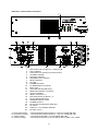
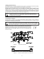
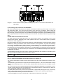
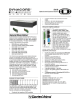
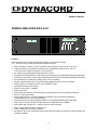
OWNER’S MANUAL
POWER AMPLIFIER DPA 4411
Features
Power amplifier with 4x100 W output power capacity according to IEC 283-3
19" - rack size (3 HU) unit that provides the following functions:
•
•
•
•
•
•
•
•
•
•
•
•
•
•
•
•
•
•
•
•
Mains operation 115/230 V AC and operation with emergency power supply of 24 V DC
Output transformers for balanced, floating 100 V loudspeaker networks: 70 V, 50 V or
4 ohms for low-impedance operation can be selected
All outputs are protected against idling and short-circuit
Integrated Remote Module for control and monitoring using the PROMATRIX Manager DPM 4000
Electronic level controls, electronically balanced inputs and electronically balanced MONITOR output
Input transformer for balanced, floating inputs can be retrofitted
Monitor output transformer for balanced, floating MONITOR output can be retrofitted
Routing switch for parallel operation of the amplifier’s inputs
Integrated Standby Power Supply
Mains function switch - POWER
Ground lift switch
Remote-Start function for mains and battery operation with inrush current limiter protection
Power-on noise attenuation
Status-LED indicators: operation (READY), STANDBY, thermal overload (PROTECT)
and GROUND FAULT at the power outputs
Fault notification according to DIN EN 60849 via the PROMATRIX Manager DPM 4000
TEST-switch for systems with average-switching or GROUND FAULT RESET
LED meters with a range from -13 dB to 0 dB plus CLIP indication
Mains voltage selector switch 115/230 V AC
Active, temperature-controlled ventilation
Modules for pilot tone surveillance and ground fault surveillance according to DIN VDE 0800 are
optionally available
19
IMPORTANT SAFETY INSTRUCTIONS
The lightning flash with arrowhead symbol, within an
equilateral triangle is intended to alert the user to the
presence of uninsulated “dangerous voltage” within the
product’s enclosure that may be of sufficient magnitude to
constitute a risk of electric shock to persons.
The exclamation point within an equilateral triangle is
intended to alert the user to the presence of important
operating and maintance (servicing) instructions in the
literature accompanying the appliance.
1.
2.
3.
4.
5.
6.
7.
8.
9.
10.
Read these instructions.
Keep these instructions.
Heed all warnings.
Follow all instructions.
Do not use this apparatus near water.
Clean only with a damp cloth.
Do not block any of the ventilation openings.
Install in accordance with the manufactures instructions.
Do not install near any heat sources such as radiators, heat registers, stoves, or other apparatus that produce heat.
Only use attachments/accessories specified by the manufacturer.
Refer all servicing to qualified service personnel. Servicing is required when the apparatus has been
damaged in any way, such as power-supply cord or plug is damaged, liquid has been spilled or objects have fallen
into the apparatus, the apparatus has been exposed to rain or moisture, does not operate normally, or has
been dropped.
For US and CANADA only:
Do not defeat the safety purpose of the grounding-type plug. A grounding type plug has two blades and a third grounding prong.
The wide blade or the third prong are provided for your safety. When the provided plug does not fit into your outlet, consult an
electrican for replacement of the absolete outlet.
IMPORTANT SERVICE INSTRUCTIONS
CAUTION: These servicing instructions are for use by qualified personnel only. To reduce the risk of
electric shock, do not perform any servicing other than that contained in the Operating
Instructions unless you are qualified to do so. Refer all servicing to qualified service
personnel.
1. Security regulations as stated in the EN 60065 (VDE 0860 / IEC 65) and the CSA E65 - 94 have to be obeyed when
servicing the appliance.
2. Use of a mains separator transformer is mandatory during maintenance while the appliance is opened, needs to be
operated and is connected to the mains
3. Switch off the power before retrofitting any extensions, changing the mains voltage or the output voltage.
4. The minimum distance between parts carrying mains voltage and any accessible metal piece (metal enclosure),
respectively between the mains poles has to be 3 mm and needs to be minded at all times.
The minimum distance between parts carrying mains voltage and any switches or breakers that are not connected
to the mains (secondary parts) has to be 6 mm and needs to be minded at all times.
5. Replacing special components that are marked in the circuit diagram using the security symbol (Note) is only permissible
when using original parts.
6. Altering the circuitry without prior consent or advice is not legitimate.
7. Any work security regulations that are applicable at the location where the appliance is being serviced have to be strictly
obeyed. This applies also to any regulations about the work place itself.
8. All instructions concerning the handling of MOS - circuits have to be observed.
Note:
SAFETY COMPONENT (HAS TO BE REPLACED WITH ORIGINAL PART ONLY)
20
Indicators, Controls And Connections
1
2
3
4
5
6
7
8
9
10
11
12
13
14
15
16
17
18
19
20
21
22
23
A
B
C
D
Rear plate screws:
heat-sink-mounting:
PCB-mounting:
socket-mounting:
LED meters with a range from -13 dB to 0 dB
CLIP indicators
TEST button for checking and reset function
STANDBY indicator
PROTECT indicator
GROUND FAULT indicator
READY indicator
Air inlets
POWER ON switch
AC MAINS INPUT connector
Mains fuse
VOLTAGE SELECTOR switch
REMOTE CONTROL connectors
STATUS indicator
INPUT connectors 1-4
ROUTING switch for INPUT 1-4
Device address label field
ADDRESS selector switch
POWER OUTPUT
Device output configuration label field
Air outlets
CIRCUIT ⊥ TO CHASSIS SWITCH
DC INPUT 24 V =
6 oval-head sheet-metal screws 3.5 x 6.5 zinc-coated DIN 7981
4 oval-head sheet-metal screws 3.5 x 9.5 zinc-coated DIN 7981
9 oval-head screws M3 x 12 nickel-plated DIN 7985
8 oval-head screws PT-KA 30 x 8 WN-1412EJOT black, zinc-coated
21
Table of Contents
Features . . . . . . . . . . . . . . . . . . . . . . . . . . . . . . . . . . . . . . . . . . . . . . . . . . . . . . . . . . . . 19
Indicators, Controls And Connectors . . . . . . . . . . . . . . . . . . . . . . . . . . . . . . . . . . . . . . 21
1. Utilization . . . . . . . . . . . . . . . . . . . . . . . . . . . . . . . . . . . . . . . . . . . . . . . . . . . . . . . . . 23
2. Installation Notes . . . . . . . . . . . . . . . . . . . . . . . . . . . . . . . . . . . . . . . . . . . . . . . . . . 23
3. Before Initial Operation . . . . . . . . . . . . . . . . . . . . . . . . . . . . . . . . . . . . . . . . . . . . . . 23
3.1 Mains Operation . . . . . . . . . . . . . . . . . . . . . . . . . . . . . . . . . . . . . . . . . . . . . . . . 23
3.2 Battery Operation 24 V DC . . . . . . . . . . . . . . . . . . . . . . . . . . . . . . . . . . . . . . . . 24
4. Inputs . . . . . . . . . . . . . . . . . . . . . . . . . . . . . . . . . . . . . . . . . . . . . . . . . . . . . . . . . . . 24
5. Outputs . . . . . . . . . . . . . . . . . . . . . . . . . . . . . . . . . . . . . . . . . . . . . . . . . . . . . . . . . . 25
5.1 POWER OUTPUT . . . . . . . . . . . . . . . . . . . . . . . . . . . . . . . . . . . . . . . . . . . . . . 25
5.2 POWER OUTPUT for the connection of 100 V loudspeaker systems . . . . . . 25
5.3 POWER OUTPUT for the connection of low-impedance loudspeaker systems 25
5.4 POWER OUTPUT 100 V - Double Output Power . . . . . . . . . . . . . . . . . . . . . . 26
5.5 MONITOR Output . . . . . . . . . . . . . . . . . . . . . . . . . . . . . . . . . . . . . . . . . . . . . . . 26
6. Integrated Remote Module . . . . . . . . . . . . . . . . . . . . . . . . . . . . . . . . . . . . . . . . . . . 26
7. Indicators And Fault Notification . . . . . . . . . . . . . . . . . . . . . . . . . . . . . . . . . . . . . . . 27
7.1 STANDBY Indicator . . . . . . . . . . . . . . . . . . . . . . . . . . . . . . . . . . . . . . . . . . . . . 27
7.2 READY Indicator . . . . . . . . . . . . . . . . . . . . . . . . . . . . . . . . . . . . . . . . . . . . . . . . 27
7.3 PROTECT Indicator . . . . . . . . . . . . . . . . . . . . . . . . . . . . . . . . . . . . . . . . . . . . . 27
7.4 GROUND FAULT Indicator . . . . . . . . . . . . . . . . . . . . . . . . . . . . . . . . . . . . . . . . 28
7.5 Meter Instruments And CLIP Indicators . . . . . . . . . . . . . . . . . . . . . . . . . . . . . . 28
7.6 STATUS Indicator . . . . . . . . . . . . . . . . . . . . . . . . . . . . . . . . . . . . . . . . . . . . . . . 28
8. Switching The Output Voltage (refer to qualified service personnel only!) . . . . . . . 28
9. Additional Functions And Features (refer to qualified service personnel only!) . . 29
9.1 NRS 90206 Pilot Tone Surveillance . . . . . . . . . . . . . . . . . . . . . . . . . . . . . . . . . 29
9.2 NRS 90207 Ground Fault Surveillance . . . . . . . . . . . . . . . . . . . . . . . . . . . . . . 30
9.3 NRS 90208 Input Transformer . . . . . . . . . . . . . . . . . . . . . . . . . . . . . . . . . . . . . 31
9.4 NRS 90227 Monitor Output Transformer . . . . . . . . . . . . . . . . . . . . . . . . . . . . . 32
10. 19"-Flightcase Or 19"-Rack System Installation . . . . . . . . . . . . . . . . . . . . . . . . . . 32
11. Ground Lift Switch CIRCUIT ⊥ TO CHASSIS SWITCH . . . . . . . . . . . . . . . . . . . . 33
12. Fuses . . . . . . . . . . . . . . . . . . . . . . . . . . . . . . . . . . . . . . . . . . . . . . . . . . . . . . . . . . . 33
13. DPA 4411 Specifications . . . . . . . . . . . . . . . . . . . . . . . . . . . . . . . . . . . . . . . . . . . . 35
14. Specifications For DPA 4411 Accessories . . . . . . . . . . . . . . . . . . . . . . . . . . . . . . . 36
14.1 NRS 90206 Pilot Tone Surveillance . . . . . . . . . . . . . . . . . . . . . . . . . . . . . . . . 36
14.2 NRS 90207 Ground Fault Surveillance . . . . . . . . . . . . . . . . . . . . . . . . . . . . . 36
14.3 NRS 90208 Input Transformer . . . . . . . . . . . . . . . . . . . . . . . . . . . . . . . . . . . . 36
14.4 NRS 90227 Monitor Output Transformer . . . . . . . . . . . . . . . . . . . . . . . . . . . . 36
15. Block Diagrams . . . . . . . . . . . . . . . . . . . . . . . . . . . . . . . . . . . . . . . . . . . . . . . . . . . 55
15.1 DPA 4411 Power Amplifier . . . . . . . . . . . . . . . . . . . . . . . . . . . . . . . . . . . . . . . 55
15.2 NRS 90206 Pilot Tone Surveillance . . . . . . . . . . . . . . . . . . . . . . . . . . . . . . . . 56
15.3 NRS 90207 Ground Fault Surveillance . . . . . . . . . . . . . . . . . . . . . . . . . . . . . 57
22
1. Utilization
The amplifier DPA 4411 has been specially designed to ensure durable performance and reliable
operation of sound reinforcement systems with several independent loudspeaker lines. The DPA 4411 is
best suited for call and message transmission installations, alert systems, and for general music
applications in industrial enterprises, offices, multi-function halls and sport arenas, schools, churches,
hotels, hospitals, super markets, cruise ships, and similar applications.
2. Installation Notes
When installing or mounting the amplifier, it is important to make sure that unhindered air-flow from the
air inlets on the front to the air outlets on the rear of the appliance is guaranteed (see paragraph 10).
To maintain EMV disturbance-free operation, the use of shielded cable for all input, output and control
lines, except for mains supply and battery cords, is mandatory. When installed inside of metal housings
or rack systems, running unshielded output and control lines is possible. Cable screens have to be
connected to the enclosure or rack system ground potential.
The amplifier has to be protected against:
- dropping or splashing water
- direct sunlight
- high environmental temperatures or direct radiation of heat sources
- high humidity and moisture
- dust
- shock or vibration
It is not permissible to place containers filled with liquids - e. g. vases - ontop of the appliance
When moving the amplifier from cold into warm environments, condensation of its inner parts can
sometimes occur. If so, the appliance can be operated again after gaining the environmental temperature
(approximately after one hour).
If a solid object has fallen or liquid has leaked into the device, disconnect all connectors and get in contact
with an authorized DYNACORD service center. Do not operate the amplifier after such accidents.
When cleaning the amplifier’s outside enclosure, never use any cleaning sprays or detergents, because
of inflamability. The use of those liquids will damage the appliance.
3. Before Initial Operation
3.1 Mains Operation
When operated on mains power, use the included mains cord to connect the amplifier to a 230 V or 115
V 50/60 Hz wall outlet. Connect the cable’s other end to the appliance’s 3-pole machine-type socket (10).
Caution
The amplifier is factory-set to 230 V AC. To change the setting to 115 V AC, use the
voltage switch (12).
For the operation with 115 V AC, the mains fuse (11) has to be replaced by an 8 Ampère
slow-blow fuse with the label print “T8AL” (see also paragraph 12).
When correctly connected and with mains power present the green STANDBY indicator (4) will light. Now,
through sending the corresponding command via the serial interface of the Remote Module, it is possible
to start the amplifier from the PROMATRIX Manager DPM 4000 (see PROMATRIX handbook).
The POWER switch (9) on the rear of the amplifier – for bridging the starting relay – is meant for service
purposes only. It offers the possibility to operate the amplifier without remote start.
Note
The POWER switch (9) on the rear of the appliance is for service purposes only. Remote
power-off is not possible with the POWER switch set to ON. In this case, the STANDBY
indicator (4) provides no function.
The DPA 4411 is equipped with a cut-in delay of approximately 3 seconds to efficiently suppress power-on
noise. After this period of time and when no fault was detected, the green READY indicators (7) will light
(see paragraph 7.2).
23
3.2 Battery Operation 24 V DC
The amplifier DPA 4411 can either be operated on the AC mains or connected to an external 24 V battery
power source. Switching to battery operation is accomplished via internal relay.
The battery has to be connected to the corresponding socket (23) on the rear panel of the appliance using
insulated AMP flat connectors 6.3x0.8 mm. The amplifier is protected against confusion of poles.
Additional internal protection is provided through two miniature fuses – F502 and F503 – one per each
conductor (+ and -), which are located on the printed board assembly 85272 (see paragraph 12, diagram
2
11). For the DPA 4411 the battery cable’s diameter should be at least 2.5 mm and the cable length for
the single distance should not exceed 4.0 m (max. drop in voltage < 1V).
Caution
Operation of the DPA 4411 is solely allowable using batteries without grounding or
batteries with grounding of the negative pole. Operation with batteries with grounding of
the positive pole is not permissible.
4. Inputs INPUT 1 to INPUT 4
The inputs INPUT 1 to INPUT 4 (15) are electronically balanced. With a sensitivity of 775mV = 0dBu they
are meant for the connection of control amplifiers. For the case that floating inputs are needed, the inputs
are prepared for retrofitting input transformers.
Note
If a switch-contact is located between the control amplifier output and the power amplifier
input, switch clicks might become audible during switching. If this is the case, incorporating
input transformers (NRS 90208 - one per input) can solve the problem (see paragraph 9.3)
Parallel operation of INPUT 1 to INPUT 4 (15) is possible when using the ROUTING
switches (16). This allows to connect the input signal through to feed several power
amplifiers with the identical program. Use a permanent marker pen to mark the
needed setting of the ROUTING switches (16) next to the ROUTING switch
push-button symbol.
diagram 1
diagram 2
input socket connection
LF-cable for coupled operation of two DPA 4411
24
5. Outputs
5.1 POWER OUTPUT
All power outputs are balanced and floating. When factory-shipped, the outputs are pre-configured for the
connection of 100 V loudspeaker systems. Connection is achieved through plugging the supplied 8-pole
socket into the connection strip (19). Switching the output transformer allows to change the output voltage
to 70 V, 50 V or 20 V (see paragraph 8). When set to 20 V, operation of low impedance speakers with a
load of 4 ohms is possible.
Caution
During operation it is possible that the outputs of the POWER OUTPUT connector may
conduct dangerous voltage (>34 V in peaks). Therefore, observing applicable safety
regulations is mandatory when connecting and installing loudspeaker lines
(see also paragraph 9.2).
5.2 POWER OUTPUT for the connection of 100 V loudspeaker systems
The use of speaker systems with 100 V matching transformers is recommended to reduce the lack in
performance when the distance between amplifier and speaker systems exceeds 50 m. This m ethod also
offers an easy way to distribute the output power. The total power consumption of the maximum amount
of the connected speakers in the network has to match the amplifier’s overall output capacity of 100 watts
(connection impedance 100 ohms). The connection is accomplished via the 100 V output (19)
(see figure 3).
diagram 3 Connection of 100 V (70 V or 50 V) loudspeaker systems
5.3 POWER OUTPUT for the connection of low-impedance loudspeaker systems
When switching the output to 20 V, low-impedance speaker systems (4-16 ohms) can be connected to
the corresponding output (see diagram 4). Because of line attenuation, the distance between amplifier
and speaker systems should not exceed 50 m. It is of further importance that the overall impedance of
the speakers does not decline 4 ohms and that the individual power handling capacity of each speaker
is not exceeded.
diagram 4 Connection of low-impedance loudspeaker systems
25
Free combination of the DPA 4411’s power output voltages, including mixed 100 V and low impedance
(4 ohms) operation, is possible.
5.4 POWER OUTPUT 100 V - Double Output Power
If the output power of one output of the DPA 4411 is not sufficient to feed all cabinets within a speaker
network and dividing the speaker chain is not an option, it is possible to double the output power by
coupling the outputs of two amplifiers. In that case the amplifier inputs have to be paralleled and the
outputs are connected in series. For the connection of inputs, please refer to paragraph 4. For the
connection of the loudspeaker network, refer to diagram 5.
Coupling is possible under the following restrictions: only identical amplifiers or power amps can be
connected. Since doubling the output voltage comes along with serial connection, it is necessary to switch
the outputs of both amplifiers to 50 V (see also paragraph 8), resulting again in an overall output voltage
of 100 V. In this case the speaker chain’s minimum load impedance is 50 ohms // 50 nF. The input level
controls of the corresponding channels of the DPA 4411 have to be set to equal values (refer also to the
PROMATRIX handbook).
This results in the following output combinations with a single DPA 4411:
4 x 100 W or 2 x 100 W + 1 x 200 W or 2 x 200 W.
diagram 5
Possible output configuration of the DPA 4411
5.5 MONITOR output
The MONITOR output of the DPA 4411 is configured as monitor bus. It gets connected to thePROMATRIX
Manager DPM 4000 via the serial port REMOTE CONTROL (13). If a floating output is needed, the output
is prepared for retrofitting a monitor output transformer. In this case the extension NRS 90227 is necessary
(see paragraph 9.4). The low-impedance monitor output is electronically balanced. Therefore, the
connected cables may be up to approx. 200 m in length.
The PROMATRIX Manager DPM 4000 (see PROMATRIX handbook) offers connection for monitor
amplifiers; which can be set to input-monitoring or output-monitoring for the desired amplifier channel.
6. Integrated Remote Module
The integrated remote module of the power amplifier DPA 4411 provides the following functions:
•
•
•
•
input levels of INPUT 1 to INPUT 4 can be set via programmable audio level controls
reading level values of the audio level controls
setting level offsets 1 to 4 via virtual controllers
mute function 1 to 4 (via level controls)
26
• mains operation remote control ON/OFF
• battery operation remote control ON/OFF
• monitoring and fault message transmission via the PROMATRIX Manager DPM 4000; in accordance
to DIN EN 60849 standard
− thermal overload of the mains transformer
− thermal overload of power output stages 1 to 4
− monitoring of the functioning of the power output stages 1 to 4 via pilot tone signal (optional, only with
NRS 90206 installed)
− ground fault detection for loudspeaker lines 1 to 4 (optional, only with NRS 90207 installed)
− measuring of input and output level peaks 1 to 4
− measuring of output voltages / levels of the power outputs 1 to 4
− measuring of output currents of the power outputs 1 to 4
− monitoring of connected loads 1 to 4 via current-voltage-measuring
− recognition of amplifier type including user-definable name
− reading of software revision of the remote module
− reading of error flags
− reading of the output configuration
− recognition of extensions NRS 90206 and NRS 90207
• switching the input monitor / output monitor 1 to 4 to the monitor bus
• pilot tone signal ON/OFF (optional, only with NRS 90206 installed)
• ground fault error flags reset
Note
Prior to the first operation of the amplifier DPA 4411, you have to set the amplifier address
using the two Hexadecimal Code switches ADDRESS (18) (refer to the PROMATRIX
handbook) and using a waterproof marker pen mark the setting in the ADDRESS label field
on the rear panel of the appliance.
By sending the corresponding command via the serial port REMOTE CONTROL (13) of the remote
module, this function is activated from the PROMATRIX Manager DPM 4000 (see PROMATRIX
handbook).
7. Indicators And Fault Notification
7.1 STANDBY Indicator
When correctly connected and with mains voltage and/or battery voltage present, the green STANDBY
indicator (4) lights.
7.2 READY Indicator
The power amplifier DPA 4411 provides a power-on delay of approximately 3 s to prevent switch clicks
from becoming audible. If after this period of time no faulty condition has been detected, the green READY
indicator (7) lights and the mute-relays pull. When thermal overload of the mains transformer or of one of
the power output stages is detected, the corresponding green READY indicator (7) will not light and the
according mute-relay drops. If, with the NRS 90206 extension installed the pilot-threshold (see paragraph
9.1) is declined, the corresponding green READY indicator (7) goes out but the amplifier stays operational
and a fault message gets transmitted to the PROMATRIX Manager DPM 4000.
7.3 PROTECT Indicator
In case of thermal overload of the mains transformer or of a power output stage is detected, the red
PROTECT indicator (5) will light. During thermal overload of the mains transformer, all mute-relays drop
while during thermal overload of a power output stage, only the according mute-relay drops. After the
mains transformer or the power amplifier have regained their normal temperature, the red PROTECT
indicator (5) automatically goes out and the appliance recovers normal operation mode. The faulty
condition could have been caused by either overload, too high environmental temperature, or by an error
in the ventilation system. A fault-message is transmitted to the PROMATRIX Manager DPM 4000.
27
7.4 GROUND FAULT Indicator
If, with built-in NRS 90207 a ground fault condition at one of the power outputs occurs, the corresponding
red GROUND FAULT indicator (6) lights and a fault-message is transmitted to the PROMATRIX Manager
DPM 4000. The power amplifier keeps up normal operation during the occurrence of this fault-type. After
solving the problem, the GROUND FAULT indicator (6) can be reset by pressing the TEST button (3) or
by sending the corresponding command via the serial port of the PROMATRIX Manager DPM 4000 (see
PROMATRIX handbook) (see paragraph 9.2).
7.5 Meter Instruments And CLIP Indicators
The green LED-indicator -13 dB and 0 dB (1) as well as the red LED-indicator CLIP (2) allow the precise
monitoring of output levels, providing the possibility to securely prevent distortion and clipping that could
lead to damaging the connected loudspeaker systems.
- When during program peaks the red CLIP-LED (2) lights briefly, the maximum distortion-free output
is gained.
- Whenever the CLIP-LED (2) lights continuously, the amplifier is driven into overdrive and the input level
should be reduced.
- Overload or short-circuit at the output is the cause for the green LED-indicator (1) to be out or only briefly
lit while at the same time the red CLIP-LED (2) blinks. In that case, please check the impedance of the
connected load.
Caution
During normal operation, the red CLIP-LED (2) should hardly light and if, than
only very briefly !
7.6 STATUS Indicator
The yellow STATUS-LED (14) that is located on the rear of the appliance lights briefly during normal
operation when the DPM 4000 addresses a query to the amplifier. For further information, please refer to
the PROMATRIX handbook.
8. Switching The Output Voltage (refer to qualified service personnel only!)
The DPA 4411 offers output voltages of either 20 V, 50 V, 70 V or 100 V. The output voltage is
factory-preset to 100 V. Switching the output voltage to 20 V, 50 V or 70 V should only be carried out by
qualified DYNACORD service personnel.
Caution
Unplug the mains cord and disconnect batteries before opening the appliance!
- for opening the appliance, please remove the 9 screws on the top of the appliance that lock the cover
plate.
- the four output transformers 356762 are located on the left hand side of the appliance. They are
numbered 1, 2, 3, and 4; starting from the rear cover plate of the appliance.
- for changing the output voltage (see diagram 6) you have to unsolder the orange wire attached to the
transformer’s soldering tab 19 (100 V) and solder it instead to the required soldering tab (70 V, 50 V or
20 V).
- closing the appliance: use the 9 screws M3 x 6 DIN 7500 to reattach the cover plate.
diagram 6
diagram 7
Switching the output voltage at the
output transformers 356762
28
Output configuration settings of the
amplifiers (rear view)
Note
diagram 8
After changing the output voltage, use a waterproof marker pen to note the correct, newly
set value on the label-field OUTPUT VOLTAGE (20) on the rear of the appliance.
Additionally note the corresponding output configuration (see diagram 5) on the label OUT
CONFIG TYPE (20).
According to the description in diagram 7, adjust the switches S801 and S802 on the printed
board assembly 89019.2 that are located next to the transformers on the bottom of the
appliance’s enclosure (refer also to paragraph 5.4 ).
Printed board assembly 89019.2 showing the position of the switches S801 and S802
9. Additional Functions And Features (refer to qualified service personnel only!)
9.1 NRS 90206 Pilot Ton Surveillance
Using the extension-kit NRS 90206 provides continuous monitoring (surveillance) of the individual
amplifier channels. This is achieved by sending an ultra low-level 19 kHz pilot tone through the device. It
enters the signal path post level controls, runs through the amplification stages and gets filtered out and
evaluated at the output. In case the result of this evaluation shows that the pilot dropped beneath a defined
threshold or is missing at all, the corresponding READY indicator AMP 1 - 4 (7) goes out but the power
amplifier upholds its normal operation. A fault-message is transmitted to the PROMATRIX Manager DPM
4000 (see PROMATRIX handbook). The extension-kit NRS 90206 comes as a plug-in board assembly
and consists of a 19 kHz tone-generator and four selective 19 kHz receivers with evaluation stage.
Caution
Unplug the mains cord and disconnect batteries before opening the appliance!
9.1.1 To Install The NRS 90206 Proceed As Follows (see diagram 9):
- for opening the appliance, please remove the 9 screws on the top of the appliance that lock the cover
plate.
- the NRS 90206 gets retrofitted on the printed board assembly 89019.1, which is located behind the input
printed board assembly 81331, in the front area, attached to the left side panel of the amplifier (in front
view).
- Be sure to first insert the included board-guides before installing the printed board assembly, assuring
the correct position of their guide grooves. The release lever of the guides marked “A” points to the top,
while the one of the guides marked “B” points downwards.
- the NRS 90206 extension-kit needs to be inserted with its printed side pointing to the top, until it firmly
locks in place. Make sure that the power resistors R917 to R920 that are located underneath the
NRS-printed board assembly do not touch this board.
- closing the appliance: use the 9 screws M3 x 6 DIN 7500 to reattach the cover plate.
29
diagram 9
Printed board assembly 89019.1 showing the position of the modules NRS 90206 and
NRS 90207
9.1.2 Checking The Function Of The NRS 90206:
With built-in NRS 90206 and powered-on amplifier, the READY-indicators (7) have to light. Use the check
and reset-button TEST (3) to check the functioning of the pilot tone surveillance. When holding the
TEST-button pressed, the 19 kHz tone-generator is switched off, the READY-indicators (7) go out and a
fault-message is being transmitted to the PROMATRIX Manager DPM 4000 (see PROMATRIX handbook). Approximately 3 seconds after releasing the TEST-button, the READY-indicators (7) have to light
again.
9.2 NRS 90207 Ground Fault Surveillance
The VDE regulation DIN VDE 0800 has to be obeyed when planning and operating 100 V sound
reinforcement systems. Especially 100 V alert systems have to be in accordance with all protection
measures for class 3 appliances.
We recommend the use of the ground fault surveillance module NRS 90207 for floating speaker network
installations, offering surveillance of the network insulation. Error registration: A ground fault message
signals that a damaged cable has been detected – possibly resulting in an upcoming cable interruption –
or a wrongly connected cable, possibly resulting in malfunctioning. The information “ground fault” is
memorized as long as the amplifier is powered on or a loaded battery is connected, even for short-term
( > 5 s) ground faults. The fault-message is transmitted to the PROMATRIX Manager DPM 4000 (see
PROMATRIX handbook).
The NRS 90207 extension comes as a plug-in printed board assembly and consists of a monitoring circuit
with error-storage and display-driver for four 100 V outputs.
Caution
Unplug the mains cord and disconnect batteries before opening the appliance!
9.2.1 To Install The NRS 90207 Proceed As Follows (see diagram 9):
- for opening the appliance, please remove the 9 screws on the top of the appliance that lock the cover
plate.
- the NRS 90207 gets retrofitted on the printed board assembly 89019.1, which is located behind the input
printed board assembly 81331, in the front area, attached to the left side panel of the amplifier (in front
view).
- Be sure to first insert the included board-guides before installing the NRS 90207, assuring the correct
position of their guide grooves. The release lever of the guides marked “C” points to the top, while the
one of the guides marked “D” points downwards.
- the NRS 90207 extension-kit needs to be inserted with its printed side pointing to the top, until it firmly
locks in place. Make sure that the power resistors R917 to R920 that are located underneath the
NRS-printed board assembly do not touch this board.
- closing the appliance: use the 9 screws M3 x 6 DIN 7500 to reattach the cover plate.
30
9.2.2 Checking The Function Of The NRS 90207:
With built-in NRS 90207 and powered-on amplifier, the READY-indicators (7) have to light. When using
an external switch to shortcut one pole of the 100 V speaker network via a 47 k ohms resistor and the
safety earthing conductor for approximately 5 seconds, the corresponding GROUND FAULT indicator (6)
has to light. The fault-message is transmitted to the PROMATRIX Manager DPM 4000 (see PROMATRIX
handbook). After releasing the external switch, indication and message have to stay present. Use the
TEST-button (3) to reset the ground fault surveillance function.
9.3 NRS 90208 Input Transformer For Floating, Balanced Inputs
In case floating inputs are needed, the inputs of the DPA 4411 are prepared for retrofitting input
transformers; a separate NRS 90208 extension-kit is needed per input.
Note
Caution
If a switch-contact is located between the control amplifier output and the power amplifier
input, switch clicks might become audible during switching. If this is the case, incorporating
input transformers can solve the problem.
Unplug the mains cord and disconnect batteries before opening the appliance!
9.3.1 Retrofitting The NRS 90208 On The Printed Board Assembly 81331:
- for opening the appliance, please remove the 9 screws on the top of the appliance that lock the cover
plate
- detach the rear panel by removing the screws marked “A” to “D” (refer to the picture of the rear panel
on page 21).
- remove the input printed board assembly 81331: (see diagram 10)
remove the 8 screws marked “D” that tighten the input sockets and detach the 6 flat cables CN1 to CN6.
For removing the printed board assembly 81331 you have to unscrew the two screws on the side panel
- before installing the input transformer, make sure to unsolder the resistors for T1: R1/R5, for T2:
R9/R13, for T3: R17/R21, for T4: R25/R29 and clean the corresponding eyelets
- place the input transformer onto the printed board assembly 81331, so that the markings on the board
and on the bottom part of the transformer are aligned. As a protection against short-circuit, place the
supplied insulating disk between the printed board and the transformer
- before re-installing the printed board assembly 81331, reconnect the flat cables CN1 to CN6. Keep in
mind that the plug of the cable leading to CN1 (AMP1+2) is marked. Now, reconnect the printed board
assembly 81331 to the amplifier’s side panel, using two screws M3 x 12
- installation of the rear panel:
first, connect the POWER OUTPUT printed board assembly to the rear panel, using two screws marked
“C”. Make sure not to squeeze any wires. Now, you can slide the rear panel underneath the four
lock-fish-plates of the input sockets. In doing so, mind that the acknowledge button of the ROUTING
switches need to be pulled through the corresponding openings
input sockets are tightened with two screws marked “D”, each
the power supply printed board assembly 85272 gets tightened using two screws marked “C”; mind the
acknowledge button of the CIRCUIT ⊥ TO CHASSIS SWITCH.
tighten the Remote Control printed board assembly with two screws marked “C”; mind the yellow
STATUS-LED
tighten the mains-input printed board assembly 86243 using three screws marked “C”; tighten the mains
connector (10) and the mains selector switch (12) with individual screws and self-securing nuts M3
reinstall the rear panel using 6 screws marked “A”
tighten the heat sink using four screws marked “B”
- closing the appliance: reconnect the cover-plate using 9 screws M3 x 6 DIN 7500
31
diagram 10 Printed board assembly 81331 showing the position of the input transformers NRS 90208
9.4 Monitor Output Transformer NRS 90227 Offering A Floating, Balanced MONITOR Output
In case a floating MONITOR output is needed, the monitor amplifier’ output is prepared for retrofitting an
output transformer. Herefore, you will need the extension kit NRS 90227.
Caution
Unplug the mains cord and disconnect batteries before opening the appliance!
9.4.1 To Install The NRS 90227 Proceed As Follows: (see diagram 10)
-
-
for opening the appliance, please remove the 9 screws on the top of the appliance that lock the
cover plate.
de-install the input printed board assembly 81331 following the description in the paragraph 9.3.1.
disconnect the resistors R95, R96, R97 and R101 before installing the monitor output transformer.
mount the monitor output transformer on the printed board assembly 81331; in doing so, polarity is
of no importance, since the transformer is balanced.
reinstall the input printed board assembly 81331 following the description in paragraph 9.3.1.
closing the appliance: use the 9 screws M3 x 6 DIN 7500 to reattach the cover plate.
10. 19"-Flightcase Or 19"-Rack System Installation
Caution
Operating the DPA 4411 without cover-plate is not admissible.
When incorporating the DPA 4411 into a 19" flightcase or 19" rack system, make sure to leave room for
sufficient air-flow. Between the amplifier’s rear plate and the inside-wall of the surrounding enclosure has
to be at least 60 mm x 330 mm of space until up to the enclosures top or its ventilation gaps. At least 100
mm of space should be left above a rack system to guarantee sufficient air circulation. Since, during the
operation of the DPA 4411 the environmental temperature within the rack closet may increase by about
10° C, minding the maximum allowable temperature values for other equipment that is installed into the
same rack system or enclosure is of major importance.
Note
For trouble-free operation of the appliance, the maximum environmental temperature
of +40 °C is not to be exceeded.
32
11. Ground Lift Switch CIRCUIT ⊥ TO CHASSIS SWITCH
Using the ground lift switch CIRCUIT ⊥ TO CHASSIS SWITCH (22) lets you separate the audio signal
ground from the enclosure ground (safety earthing). This helps to solve problems with hum or noise without
jeopardizing safety standards. If several units with ground lift switch are installed in a common enclosure
or rack system, it is recommended to set the ground lift switches of all devices but one to “ungrounded”.
Set to “ungrounded”, the impedance between signal ground and enclosure is: 100 k ohms // 100 nF. It is
necessary to maintain the immunity from EMV.
12. Fuses
Location
Pos.
Used for
Value
Dimensions
Standard
Fuse switch (11)
Fuse switch (11)
Board 86243
Board 85272
Board 85272
Board 85272
Board 85272
Board 85272
Board 85272
F601
F601
F602
F502
F503
F504
F505
F506
F507
Mains fuse 230 V~ AC
Mains fuse 115 V~ AC
Mains fuse AC
Battery fuse 24 V DC
Battery fuse 24 V DC
Power-AMP 1
Power-AMP 2
Power-AMP 3
Power-AMP 4
T4AL 250V
T8AH 250V
T1AL 250V
25AL 32V
25AL 32V
T6.3AL 250V
T6.3AL 250V
T6.3AL 250V
T6.3AL 250V
5 x 20 mm
5 x 20 mm
8.5 x 8.45 mm
Flat type fuse
Flat type fuse
5 x 20 mm
5 x 20 mm
5 x 20 mm
5 x 20 mm
IEC 127
IEC 127
IEC 127
DIN 72581-3
DIN 72581-3
IEC 127
IEC 127
IEC 127
IEC 127
Changing The Fuses F502 And F503 (see diagram 11):
Caution
Unplug the mains cord and disconnect batteries before opening the appliance!
The battery fuses F 502 and F503 are located on the mains (power supply) printed board assembly 85272
behind the AMP-battery connectors. In case they need to be replaced, commence as follows:
-
open the appliance by removing the 9 screws that lock the cover-plate
-
remove the mains input printed board assembly 86243 that is located at the rear inner wall.
Therefore, unplug the yellow/green ground conductor form the corresponding connector at the rear
inner wall. To remove the AMP-plug, press its lock-piece
-
now, you have to remove the 3 screws of the mains-input printed board assembly 86243 marked “C”
(refer to the picture of the rear panel on page 21).
-
disconnect the 6-pole flat cable between the two relays on the mains-input printed board assembly
86243 that is connected to the male multi-point connector B602
-
now, the hinged mains-input printed board assembly 86243 can be turned up. In doing so, be careful
not to damage any wiring or other parts
-
the fuses F502 and F503 are now easy to get to and can be removed to the top
-
for re-installing the mains-input printed board assembly 86243, proceed in opposite order:
tighten the mains-input printed board assembly 86243 with the 3 screws marked “C”, where each,
the mains plug (10) and the mains selector switch (12) need to be connected using individual screws
and self-securing nuts M3.
-
reconnect the 6-pole flat cable to the multi-point connector B602
-
reconnect the yellow/green ground cord to the ground connector on the rear panel; make sure that it
sits tight
-
closing the appliance: reattach the cover-plate with 9 screws M3 x 6 DIN 7500
33
Caution
diagram 11
For safety reasons make sure that after reassembling, wires running underneath the
mains-input printed board assembly 86243 are run with a minimum distance
of at least 6 mm.
Printed board assembly 85272 showing the position of the DC-fuses F502 to F507
34
13. DPA 4411 Specifications
Power supply on mains operation:
operation voltage
mains frequency range
safety class
115 V / 230 V~ AC, ±10 %
50 - 60 Hz
I
mains operation
Umains [V]
Imains [A]
Pmains [VA]
Pmains [W]
Pout [W]
Pv [W]
Standby
0idling
Normal operation (-10 dB)
Alarm (-3 dB)
Nominal conditions
230
230
230
230
230
0,016
0,29
1,64
3,25
4,39
3,7
67
377
748
1010
1,5
40
275
585
815
0
0
40
200
400
1,5
40
235
385
415
Pout [W]
Pv [W]
0
0
40
200
400
1,5
40
235
385
415
mains initial current inrush
< 36 A
mains operation
Umains [V]
Imains [A]
Pmains [VA]
Standby
0idling
Normal operation (-10 dB)
Alarm (-3 dB)
Nominal conditions
115
115
115
115
115
0,30
0,50
3,28
6,50
8,78
3,5
58
377
748
1010
mains initial current inrush
Pmains [W]
1,5
40
275
585
815
< 20 A
Pmains[VA] =apparent power Umains*Imains, Pmains[W] =true power, Pout[W] =output power, Pv[W] =leakage power
Power supply on battery operation:
operation voltage
24 V DC, -10/+30 %
battery operation
UB [V]
IB [A]
Pi [VA]
Pout [W]
Pv [W]
24
24
24
24
0,06
1,1
7,5
18
1,5
26
180
432
0
0
40
250
1,5
26
140
182
Standby
0idling
Normal operation (-10 dB)
Nominal conditions
battery initial current inrush
< 3,9 A
Pi[W] = input power UB*IB, Pout [W] = output power, Pv [W] = leakage power
input characteristics:
nominal input level
power output characteristics:
nominal output power with mains supply
nominal output voltage
with mains supply
with battery supply at 24 V DC
nominal load impedance
electronically balanced
775 mV = 0 dBu / 10 k ohms
balanced, floating
4 x 100 W (according to IEC 268-3)
100 V ( 70 V / 50 V / 20 V )
79 V ( 56 V / 40 V / 16 V )
100 ohms ( 50 / 25 / 4 ohms)
minimal allowable output impedance:
100 W output power
100 V output
70 V output
50 V output
20 V output
200 W output power
100 Ohm // 250 nF
50 Ohm // 500 nF
25 Ohm // 1000 nF
4 Ohm // 6250 nF
50 V + 50 V output
—————
—————
—————
≤ -56 dBu
≤ 1%
60 Hz .. 20 kHz
noise voltage (A-weighted)
THD at PA NOMINAL
amplification frequency response
35
50 Ohm // 500 nF
—————
—————
—————
distortion-limited response
(P A NOMINAL -3dB, kΣ = 1 %)
60 Hz .. 5 kHz
crosstalk between two channels
≥ 80dB at 1 kHz / ≥ 60dB at 10 kHz
MONITOR output characteristics:
nominal output voltage
nominal load impedance
amplification frequency response
electronically balanced
2 V = + 8.2 dBu
600 ohms
60 Hz .. 20 kHz
environmental temperature
+5 °C .. +40 °C
technical regulations:
This appliance is in accordance to the following regulations
dimensions (W x H x D)
installation depth without external connectors
installation depth incl. external connectors
weight
color
EN 55103-1, EN 55103-2, EN 55022
EN 60065, EN 60555
19“ (483 mm) x 3HU (132 mm) x 345 mm
340 mm
max. 400 mm
22.5 kg
anthracite
Extension kits for the DPA 4411:
NRS 90206
NRS 90207
NRS 90208
NRS 90227
pilot tone surveillance (for four amplifiers)
ground fault surveillance (for four outputs)
input transformer (per single input)
monitor output transformer
Order
Order
Order
Order
No.
No.
No.
No.
121
121
121
121
639
640
641
679
14. Specifications For DPA 4411 Accessories
14.1 NRS 90206 pilot tone surveillance (for four amplifiers)
pilot frequency
fault recognition threshold
fault message output
19 kHz ± 1%
≤ 12 mV
separate for each output; via
PROMATRIX Manager DPM 4000
14.2 NRS 90207 ground fault surveillance (for four outputs)
input
fault message output
loudspeaker line 20 V / 50V / 70V / 100V
separate for each output; via
PROMATRIX Manager DPM 4000
1000 Veff
≤ 50 k ohms
voltage strength
fault recognition threshold
14.3 NRS 90208 input transformer (per single input)
transmission range
input impedance
idling ratio
primary winding resistance
secondary winding resistance
20 Hz .. 20 kHz
≥ 10 k ohms
1:1
1420 ohms at 20°C
1420 ohms at 20°C
14.4 NRS 90227 monitor output transformer
transmission range
nominal load impedance
idling ratio
primary winding resistance
secondary winding resistance
40 Hz .. 20 kHz
≥ 600 ohms
1:1
18 ohms at 20°C
18 ohms at 20°C
36