1
ASAHI AV VALVES
Installation,Operation and Maintenance Manual
Serial No.
H-V019-E-6
Constant Flow Valves
User’s Manual
Contents
(1) Be sure to read the following warranty
clauses of our product
1
(2) General operating instructions
2
(3) General instructions for transportation
unpacking and storage
3
(4) Names of parts
4
(5) Specifications
6
(6) Principle & operation
7
(7) Installation procedure
8
(8) Operating procedure
10
(9) Inspection items
10
(10) Troubleshooting
11
(11) Disassembly procedure for cleaning
the inside of valve
11
(12) Handling of residual and waste materials
14
ASAHI AV VALVES
Constant Flow Valves
0
ASAHI AV VALVES
Installation,Operation and Maintenance Manual
This User’s Guide contains information important to the proper installation, maintenance and safe
use of the ASAHI AV product store in an easily accessible location.
<Warning & Caution Signs>
Warning
Caution
This symbol reminds the user to take caution due to the potential for serious
injury or death.
This symbol reminds the user to take caution due to the potential for damage to
the valve if used in such a manner.
<Prohibited & Mandatory Action Signs>
Prohibited: When operating the valve, this symbol indicates an action that
should not be taken.
Mandatory action: When operating the valve, this symbol indicates mandatory
actions that must be adhered to.
(1)Be sure to read the following warranty clauses of our product
- Always observe the specifications of and the precautions and instructions on using our product.
- We always strive to improve product quality and reliability, but cannot guarantee perfection. Therefore,
should you intend to use this product with any equipment or machinery that may pose the risk of serious
or even fatal injury, or property damage, ensure an appropriate safety design or take other measures with
sufficient consideration given to possible problems. We shall assume no responsibility for any
inconvenience stemming from any action on your part without our written consent in the form of
specifications or other documented approval.
- The related technical documents, operation manuals, and other documentation prescribe precautions on
selecting, constructing, installing, operating, maintaining, and servicing our products. For details,
consult with our nearest distributor or agent.
- Our product warranty extends for one and a half years after the product is shipped from our factory or
one year after the product is installed, whichever comes first. Any product abnormality that occurs
during the warranty period or which is reported to us will be investigated immediately to identify its
cause. Should our product be deemed defective, we shall assume the responsibility to repair or replace
it free of charge.
- Any repair or replacement needed after the warranty period ends shall be charged to the customer.
- The warranty does not cover the following cases:
(1) Using our product under any condition not covered by our defined scope of warranty.
(2) Failure to observe our defined precautions or instructions regarding the construction, installation,
handling, maintenance, or servicing of our product.
(3) Any inconvenience caused by any product other than ours.
(4) Remodeling or otherwise modifying our product by anyone other than us.
(5) Using any part of our product for anything other than the intended use of the product.
(6) Any abnormality that occurs due to a natural disaster, accident, or other incident not stemming
from something inside our product.
Constant Flow Valves
1
ASAHI AV VALVES
Installation,Operation and Maintenance Manual
(2) General Operating Instructions
Warning
Caution
- Using a positive-pressure gas with our plastic piping may pose a dangerous condition due to
the repellent force particular to compressible fluids even when the gas is under similar
pressures used for liquids. Therefore, be sure to take the necessary safety precautions such
as covering the piping with protective material. For inquiries, please contact us. For
conducting a leak test on newly installed piping, be sure to check for leaks under water
pressure. If absolutely necessary to use a gas in testing, please consult your nearest service
station beforehand.
- Since the Asahi AV constant flow valve has four types of A-D according to piping and fluid
conditions, make sure of the product specifications after removing the valve from the
packing case.
- Do not step on or apply excessive weight on valve. (It can be damaged.)
- Do not use the valve for the fluid having a viscosity of more than 35cp.
- Do not use the valve in conditions where the fluid may have crystallized.
(The valve will not operate properly.)
- Keep the valve away from excessive heat or fire. (It can be damaged, or destroyed.)
- The flow rate scale of the opening indicator has already been adjusted before the products
shipped so that the differences between reading and actual values meet the standard accuracy
within +/- 6% of full scale.
- Always operate the valve within the pressure vs. temperature range.
(The valve can be damaged or deformed by operating beyond the allowable range.)
- Allow sufficient space for maintenance and inspection.
- Select a valve material that is compatible with the media. For chemical resistance
information, refer to “CHEMICAL RESISTANCE ON ASAHI AV VALVE”.
(Some chemicals may damage incompatible valve materials.)
- Keep the valve out of direct sunlight, water and dust. Use cover to shield the valve.
(The valve will not operate properly.)
- Perform periodic maintenance. (Leakage may develop due to temperature changes or periods
of prolonged storage, rest, or operation.)
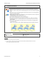
- Regardless of horizontal installation or vertical installation, the strainer with the 60-Mesh
should be installed in the upper stream line of the valve in order to avoid the malfunction
possibility caused by clogging of the valve by foreign matters. Do not set the configuration
as shown in the drawing, because it may malfunction.
(Other than ultra pure water lines.)
Fig.1
×
- Regarding Specific Gravity, it should be less than 1.4 at the size of 15mm (1/2”) to 80mm (3”)
and less than 1.1 at 100mm (4”).
Constant Flow Valves
2
ASAHI AV VALVES
Installation,Operation and Maintenance Manual
(3) General instructions for transportation, unpacking and storage
- When suspending and supporting a valve, take care and do not stand under a suspended valve.
Warning
Caution
- This valve is not designed to handle impacts of any kind.
Avoid throwing or dropping the valve.
- Avoid scratching the valve with any sharp object.
- Do not over-stack cardboard shipping boxes. Excessively stacked packages may collapse.
- Avoid contact with any coal tar creosote, insecticides, vermicides or paint.
(These chemicals may cause damage to the valve.)
- When transporting a valve, do not carry it by the handle.
- Store products in their corrugated cardboard boxes. Avoid exposing products to direct
sunlight, and store them indoors (at room temperature). Also avoid storing products in areas
with excessive temperatures. (Corrugated cardboard packages become weaker as they
become wet with water or other liquid. Take care in storage and handling.)
- After unpacking the products, check that they are defect-free and meet the specifications.
Constant Flow Valves
3
ASAHI AV VALVES
Installation,Operation and Maintenance Manual
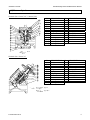
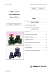
(4) Name of parts
Nominal Size: 15mm (1/2”), 20mm (3/4”)
No.
[1]
[2]
[3]
[4]
[5]
[6]
[7]
[8]
[9]
[10]
[11]
[12]
[13]
DESCRIPTION
Body
Bonnet
Cylinder
Piston
Plug
Spring base
Stop ring
Orifice
Seat
O-Ring (A)
O-Ring (B)
O-Ring (C)
O-Ring (D)
No.
[14]
[15]
[16]
[17]
[18]
[19]
[20]
[21]
[23]
[24]
[25]
[26]
DESCRIPTION
Sleeve
Cap
Key
Cap nut
Nut
Thrust ring
Spring (A)
Spring (B)
Washer (B)
Handle base
Handle cover
Screw
No.
[1]
[2]
[3]
[4]
[5]
[6]
[7]
[8]
[9]
[10]
[12]
[13]
DESCRIPTION
Body
Bonnet
Cylinder
Piston
Plug
Spring base
Stop ring
Orifice
Seat
O-Ring (A)
O-Ring (C)
O-Ring (D)
No.
[14]
[15]
[16]
[19]
[20]
[21]
[22]
[23]
[27]
[28]
[29]
DESCRIPTION
Sleeve
Cap
Key
Thrust ring
Spring (A)
Spring (B)
Washer (A)
Washer (B)
Hand Wheel
Screw
Indicator
Flow
Nominal Size: 25mm (1”)
Type A
Flow
Type B, C
Constant Flow Valves
4
ASAHI AV VALVES
Installation,Operation and Maintenance Manual
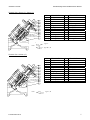
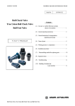
Nominal Size: 50mm (2”), 80mm (3”)
No.
[1]
[2]
[3]
[4]
[5]
[6]
[7]
[8]
[9]
[10]
[12]
[13]
DESCRIPTION
Body
Bonnet
Cylinder
Piston
Plug
Spring base
Stop ring
Orifice
Seat
O-Ring (A)
O-Ring (C)
O-Ring (D)
No.
[14]
[15]
[16]
[19]
[20]
[21]
[22]
[23]
[27]
[28]
[29]
[30]
DESCRIPTION
Sleeve
Cap
Key
Thrust ring
Spring (A)
Spring (B)
Washer (A)
Washer (B)
Hand Wheel
Screw
Indicator
O-Ring (E)
No.
[14]
[15]
[16]
[19]
[20]
[21]
[22]
[23]
[27]
[28]
[29]
[30]
DESCRIPTION
Sleeve
Cap
Key
Thrust ring
Spring (A)
Spring (B)
Washer (A)
Washer (B)
Hand Wheel
Screw
Indicator
O-Ring (E)
Type A
Flow
Type B, C, D
Nominal Size: 100mm (4”)
No.
[1]
[2]
[3]
[4]
[5]
[6]
[7]
[8]
[9]
[10]
[12]
[13]
Flow
Constant Flow Valves
DESCRIPTION
Body
Bonnet
Cylinder
Piston
Plug
Spring base
Stop ring
Orifice
Seat
O-Ring (A)
O-Ring (C)
O-Ring (D)
Type C, D
5
ASAHI AV VALVES
Installation,Operation and Maintenance Manual
(5) Specifications
● Working Temperature
● Upstream Working Pressure
: PVC = 0-50℃ (30 - 120°F), C-PVC = 0-70℃ (30 – 160°F)
: 0.25MPa
(2.6kgf / cm2) or less
0.25 to 0.5 MPa (2.6 to 5.1kgf / cm2)
0.5 to 0.75 MPa (5.1 to 7.7kgf / cm2)
0.75 to 1.0 MPa (7.7 to 10.2kgf / cm2)
* Nom. size 100mm (4”) is 0.5 MPa (5.1kgf / cm2) or less only.
0.1MPa = 14.286PSI
● A Type [ 25mm (1”) – 80mm (3”) ]
Fluid flows through the valve inside Suitable for
semi-conductor industry.
(Ultra pure water line)
Flow
● B Type [ 15mm (1/2”) – 80mm (3”) ]
Flow rate setting range is large.
(Covers small flow rate to large rate)
Flow
● C Type [ 15mm (1/2”) – 100mm (4”) ]
Range of working differential pressure is large.
(For lines with large pressure differential between
upstream & downstream)
Flow
● D Type [ 80mm (3”) – 100mm (4”) ]
A large flow rate can be set.
Flow
Constant Flow Valves
6
ASAHI AV VALVES
Installation,Operation and Maintenance Manual
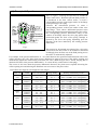
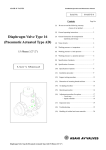
(6) Principle & Operation
Refer to Figure 1 for design and operation of ASAHI AV
Flow Control Valve. When the upstream fluid pressure, P1
is introduced at the flow control orifice, it exerts a
corresponding pressure on the upper surface of the flange
on the piston type valve plug.
Likewise, the downstream pressure, P2 exerts a
corresponding pressure to the lower surface of the valve
plug flange. Thus, when a differential pressure exists
between the fluid upstream and downstream of the orifice,
the corresponding pressure differential acting on the
surfaces of the flange moves the valve plug piston either
downward against the force of the spring cartridge or
upward by the force the spring, depending upon the
direction of the force induced by the existing pressure
differential.
Fig. 1
This upward or downward movement of the valve plug
piston causes the flow orifice to be widened or narrowed
accordingly, thus the flow rate of the fluid passing across
the orifice is automatically adjusted.
For example, if the pressure differential, P1 - P2 created between the upstream and downstream side of the
orifice increases, the valve plug piston moves downward to narrow the area of the orifice opening and
automatically adjusts the orifice to the preset flow rate value. (With the type of B, C and D, the plug has no
inlet hole for fluid, as the pressure differential P1 - P2 exerts directly on the surface of the plug.)
The reverse is also true when the pressure differential decreases, the piston moves upward increasing the
orifice opening area and allowing the fluid flow rate to increase to the preset value.
Preset flow rate range for use Design flow rate ranges:
Nom. size
TYPE
Flow rate (m3/hr)
Range ability
15mm
(1/2”)
TYPE B
TYPE C
TYPE B
TYPE C
TYPE A
TYPE B
TYPE C
TYPE A
TYPE B
TYPE C
TYPE A
TYPE B
TYPE C
TYPE D
TYPE C
TYPE D
0.04 - 0.8
0.08 - 0.8
0.06 - 1.2
0.12 - 1.2
0.5 - 2.0
0.1 - 2.0
0.2 - 2.0
2.0 - 8.0
0.4 - 8.0
0.8 - 8.0
5.0 - 20.0
1.0 - 20.0
2.0 - 20.0
15.0 - 30.0
10.0 - 60.0
30.0 - 60.0
20 : 1
10 : 1
20 : 1
10 : 1
4:1
20 : 1
10 : 1
4:1
20 : 1
10 : 1
4:1
20 : 1
10 : 1
2:1
6:1
2:1
20mm
(3/4”)
25mm
(1”)
50mm
(2”)
80mm
(3”)
100mm
(4”)
Working differential pressure
0.02 - 0.1MPa
0.03 - 0.2 MPa
0.02 - 0.1 MPa
0.03 - 0.2 MPa
0.02 - 0.1 MPa
0.02 - 0.1 MPa
0.03 - 0.2 MPa
0.02 - 0.1 MPa
0.02 - 0.1 MPa
0.03 - 0.2 MPa
0.02 - 0.1 MPa
0.02 - 0.1 MPa
0.03 - 0.2 MPa
0.03 - 0.15 MPa
0.03 - 0.2 MPa
0.02 - 0.2 MPa
(0.2 - 1.0kgf/cm2)
(0.3 - 2.0 kgf/cm2)
(0.2 - 1.0 kgf/cm2)
(0.3 - 2.0 kgf/cm2)
(0.2 - 1.0 kgf/cm2)
(0.2 - 1.0 kgf/cm2)
(0.3 - 2.0 kgf/cm2)
(0.2 - 1.0 kgf/cm2)
(0.2 - 1.0 kgf/cm2)
(0.3 - 2.0 kgf/cm2)
(0.2 - 1.0 kgf/cm2)
(0.2 - 1.0 kgf/cm2)
(0.3 - 2.0 kgf/cm2)
(0.3 - 1.5 kgf/cm2)
(0.3 - 2.0 kgf/cm2)
(0.2 - 2.0 kgf/cm2)
1m3/hr = 4.4033gal/min, 0.1MPa = 14.286PSI
Constant Flow Valves
7
ASAHI AV VALVES
Installation,Operation and Maintenance Manual
(7) Installation procedure
Warning
Caution
- When suspending and supporting a valve, take care and do not stand under a suspended
valve.
- Be sure to conduct a safety check on all hand and power tools to be used before beginning
work.
- Wear protective gloves and safety goggles as fluid remain in the valve even if the pipeline is
empty. (You may be injured.)
- When installing pipes and valves, ensure that they are not subjected to tension, compression,
bending, impact, or other excessive stress.
- Use flat faced flanges for connection to AV Valves.
- Ensure that the mating flanges are of the same standards.
- Every type of valve has its one flow direction across the valve. Make sure, therefore,
that the flow direction is consistent with the arrow-mark indicated on the valve body
when installed.
- Be sure to use sealing gaskets (AV Gasket), bolts, nuts, and washers and tighten them
to specified torques.
(When a non-AV gasket is used, a different tightening specification should be followed.)
AType
BType
Necessary items
● Spanner wrench
● Bolt, Nut, Washer (Vary per flange type)
CType
DType
● Torque wrench
● AV Gasket
Procedure
1) Set the AV Gasket between the flanges.
2) Insert washers and bolts from the pipe side, insert washers and nuts from the valve side,
then temporarily tighten them by hand.
Constant Flow Valves
8
ASAHI AV VALVES
Caution
Installation,Operation and Maintenance Manual
- The parallelism and axial misalignment of the flange surface should be under the
values shown in the following table to prevent damage the valve.
(A failure to observe them can cause destruction due to stress application to the pipe.)
Unit : mm (inch)
Nom. Size
15-25mm
(1/2”-1”)
40-80mm
(1 1/2”-3”)
100mm
(4”)
Axial
Misalignment
Parallelism
(a-b)
1.0 (0.04)
0.5 (0.02)
1.0 (0.04)
0.8 (0.03)
1.0 (0.04)
1.0 (0.04)
(Axial misalignment)
(Parallelism)
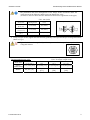
3) Using a torque wrench, tighten the bolts and nuts gradually to the specified torque in a diagonal manner
(Refer to Fig.1.)
Caution
- Tighten the bolts and nuts gradually with a torque wrench to the specified torque level in
a diagonal manner.
Fig.1
Recommended torque value
Unit: N・m{kgf・cm}[lb・inch]
15-20 mm
25 mm
50 mm
80, 100 mm
Nom. Size
(1/2”-3/4”)
(1”)
(2”)
(3”, 4”)
PTFE・
17.5{179}[155] 20.0{204}[177] 22.5{230}[230] 30.0{306}[266]
PVDF coated
20.0 {204}
22.5 {230}
30.0 {306}
Rubber
8.0 {82} [71]
[177]
[230]
[266]
Constant Flow Valves
9
ASAHI AV VALVES
Installation,Operation and Maintenance Manual
(8) Operating procedure
- Do not exert excessive force in closing the valve.
Caution
- Do not use the valve to fluid containing slurry. (The valve will not operate properly.)
- The installed valve must never be opened or closed when foreign matter such as sand
is present in the pipeline.
- When operating the handle, be sure to do so with your hand.
(Using a tool may damage the handle.)
- Follow the procedure in setting the flow rate.
○ To operate the valve for opening / closing, turn the hand wheel slowly.
(To get the flow rate decreased, turn the hand wheel clockwise.)
Caution
- To set new flow rate, turn the hand wheel counterclockwise to let the indicator of
opening degree reach beyond the required level and then the hand wheel clockwise to
obtain proper flow rate.
(This is the recommendable procedure to get exact flow rate.)
○ To shut the valve, turn the hand wheel clockwise, and adjust the indicator to the “ 0 ” position of the
flow rate scale.
Application of rubber material for shut – off seat gives the valve perfect closing with little tightening
torque.
Caution
- Do not operate the valve out of scale, especially at lower level than the minimum indicated
scale. (The function of valve could be deteriorated.)
(9) Inspection items
Caution
- Perform periodic maintenance. (Leakage may develop due to temperature changes or over
periods of prolonged storage, rest or operation.)
○ Inspect the following items
(1)
Existence of scratches, cracks, deformation, and discoloring.
(2)
Existence of leakage from the valve to the outside.
(3)
Existence of leakage when the valve is opened fully at right or left.
Constant Flow Valves
10
ASAHI AV VALVES
Installation,Operation and Maintenance Manual
(10) Troubleshooting
Problem
The flow rate is
extraordinarily small
Cause
Treatment
Insufficient Working differential
Adjust Working differential pressure.
pressure.
Foreign materials are caught.
Clean.
Appearance of algae or seaweed on
Clean.
the surface of valve inside.
Sand is caught in the valve.
Clean.
The plug is damaged or worn.
The orifice is damaged or worn.
The flow rate is larger
than the range of It has exceeded beyond the range of
recommended flow rate. Working differential pressure.
Appearance of algae or seaweed on
the surface of valve inside.
Sand is caught in the valve.
Appearance of algae or seaweed on
Fluid is not stopped in the surface of valve inside
the full shut position.
Sand is caught in the valve.
For further detail and assistance, consult
your nearest AOC agents / branches.
For further detail and assistance, consult
your nearest AOC agents / branches.
Adjust Working differential pressure.
Clean.
Clean.
Clean.
Clean.
(11) Disassembly procedure for cleaning the inside of valve
Warning
Caution
- Do not disassemble the parts not mentioned above.
- Do not try to disassemble any part that is hard to disassemble (parts stuck together).
Consult our office nearest to you.
- The flow rate scale of the opening indicator has already been adjusted before the
products shipped so that the differences between reading and actual values meet the
standard accuracy within +/- 6% of full scale.
- In case of removing the bonnet, the valve should be fully opened first, then remove
the bonnet.
- Avoid scratching the inside parts and surface of the valve with any sharp objects.
- Do not change or replace valve parts under line pressure.
Necessary items
● Strap Wrench (*Removal of the bonnet)
● Nylon Brush (*Wash The Parts)
Constant Flow Valves
● Snap Ring Plier (*Removal of the bonnet)
● Grease “Silicon Grease”
11
ASAHI AV VALVES
Installation,Operation and Maintenance Manual
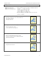
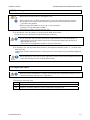
Dissassembly
1) Open the valve fully.
2) Check for marking between the body and bonnet. If there is no marking, please make alignment
marks with a marker as follows.
*Note ; No need for marking on 15mm (1/2”) and 20mm (3/4”) in nominal size.
Marking
Marking
(Using a marker)
3) Loosen the bonnet with a strap wrench, and remove it.
4) Remove the snap ring with a snap ring plier.
Snap ring
5) Remove the piston from the cylinder.
Constant Flow Valves
12
ASAHI AV VALVES
Installation,Operation and Maintenance Manual
Washing
1) Check the valve parts for damages.
2) Wash the valve parts with a nylon brush.
Assembly
1) Insert the piston into the cylinder smoothly, then insert the snap ring tightly.
2) If there is no grease around the o-ring of the cylinder, apply a sufficient amount of grease to the
surface of the o-ring.
3) Check whether the piston moves smoothly. If not, wash the valve again.
Constant Flow Valves
13
ASAHI AV VALVES
Installation,Operation and Maintenance Manual
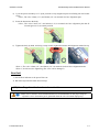
4) Cycle the piston assembly to 1/2 open position to keep alignment pins from falling into the bonnet
cavity.
*Note ; The valve 15mm (1/2”) and 20mm (3/4”) in nominal size have alignment pins.
5) Insert the bonnet into the body.
*Note ; The valve 15mm (1/2”) and 20mm (3/4”) in nominal size have alignment pins that fit
internal grooves to set normal position.
6) Tighten the body by hand, and using a strap wrench, tighten the bonnet until alignment marks line up.
*Note-1 ; The valve 15mm (1/2”) and 20mm (3/4”) in nominal size don’t have alignment marks.
*Note-2 ; Avoid excessive tightening.(The valve can be damaged.)
Run fluid
1) Set the flow indicator to the preset flow rate.
2) Run fluid. (Operate the hand wheel slowly.)
(12) Handling of residual and waste materials
Warning
- Make sure to consult a waste treatment dealer for recommendations on the proper disposal
of plastic valves. (Poisonous gas is generated when the valve is burned improperly.)
Constant Flow Valves
14
ASAHI AV VALVES
Installation,Operation and Maintenance Manual
Constant flow valve
ASAHI AV VALVES
Distributor
Information in this manual is subject to change without notice.
Asahi Organic Chemicals Industry’s homepage
Information in this manual is subject to change without notice.
Constant Flow Valves
http://www.asahi-yukizai.co.jp/en/
2011.5
15