1
Introduction
Operation Manual
Thank you for purchasing the Mini-LST2 from Losi®. This guide contains the basic instructions for operating your
new Mini Monster Truck. While the Mini-LST2 is great for first-time R/C drivers, it does require some mechanical
experience and/or adult supervision for drivers under the age of 12. It is crucial that you read all of the instructions,
safety warnings, and accompanying printed material in order to operate your new model correctly and avoid
unnecessary damage. Please take a moment to look the documentation over before running your new Mini-LST2.
Warning
resulting damage or injury. By the act of use, setup or
assembly, the user accepts all resulting liability.
An R/C model is not a toy! If misused, it can cause
serious bodily harm and damage to property. Operate
only in open areas and follow all instructions included
with your radio and model.
If you as the Purchaser or user are not prepared
to accept the liability associated with the use of
this Product, you are advised to return this Product
immediately in new and unused condition to the place of
purchase.
Warranty Period
Horizon Hobby, Inc., (Horizon) warranties that the
Products purchased (the “Product”) will be free from
defects in materials and workmanship at the date of
purchase by the Purchaser.
Law: These Terms are governed by Illinois law (without
regard to conflict of law principals).
Safety Precautions
This is a sophisticated hobby Product and not a toy.
It must be operated with caution and common sense
and requires some basic mechanical ability. Failure to
operate this Product in a safe and responsible manner
could result in injury or damage to the Product or
other property. This Product is not intended for use by
children without direct adult supervision. The Product
manual contains instructions for safety, operation
and maintenance. It is essential to read and follow all
the instructions and warnings in the manual, prior to
assembly, setup or use, in order to operate correctly
and avoid damage or injury.
Limited Warranty
(a) This warranty is limited to the original Purchaser
("Purchaser") and is not transferable. REPAIR OR
REPLACEMENT AS PROVIDED UNDER THIS
WARRANTY IS THE EXCLUSIVE REMEDY OF
THE PURCHASER. This warranty covers only those
Products purchased from an authorized Horizon
dealer. Third party transactions are not covered by this
warranty. Proof of purchase is required for warranty
claims. Further, Horizon reserves the right to change
or modify this warranty without notice and disclaims all
other warranties, express or implied.
(b) Limitations- HORIZON MAKES NO WARRANTY OR
REPRESENTATION, EXPRESS OR IMPLIED, ABOUT
NON-INFRINGEMENT, MERCHANTABILITY OR
FITNESS FOR A PARTICULAR PURPOSE OF THE
PRODUCT. THE PURCHASER ACKNOWLEDGES
THAT THEY ALONE HAVE DETERMINED THAT
THE PRODUCT WILL SUITABLY MEET THE
REQUIREMENTS OF THE PURCHASER’S INTENDED
USE.
(c) Purchaser Remedy- Horizon's sole obligation
hereunder shall be that Horizon will, at its option, (i)
repair or (ii) replace, any Product determined by Horizon
to be defective. In the event of a defect, these are the
Purchaser's exclusive remedies. Horizon reserves the
right to inspect any and all equipment involved in a
warranty claim. Repair or replacement decisions are
at the sole discretion of Horizon. This warranty does
not cover cosmetic damage or damage due to acts of
God, accident, misuse, abuse, negligence, commercial
use, or modification of or to any part of the Product.
This warranty does not cover damage due to improper
installation, operation, maintenance, or attempted repair
by anyone other than Horizon. Return of any goods
by Purchaser must be approved in writing by Horizon
before shipment.
Damage Limits
HORIZON SHALL NOT BE LIABLE FOR SPECIAL,
INDIRECT OR CONSEQUENTIAL DAMAGES, LOSS
OF PROFITS OR PRODUCTION OR COMMERCIAL
LOSS IN ANY WAY CONNECTED WITH THE
PRODUCT, WHETHER SUCH CLAIM IS BASED IN
CONTRACT, WARRANTY, NEGLIGENCE, OR STRICT
LIABILITY. Further, in no event shall the liability of
Horizon exceed the individual price of the Product on
which liability is asserted. As Horizon has no control
over use, setup, final assembly, modification or misuse,
no liability shall be assumed nor accepted for any
Questions, Assistance, and Repairs
Your local hobby store and/or place of purchase
cannot provide warranty support or repair. Once
assembly, setup or use of the Product has been started,
you must contact Horizon directly. This will enable
Horizon to better answer your questions and service
you in the event that you may need any assistance.
For questions or assistance, please direct your
email to [email protected], or call
877.504.0233 toll free to speak to a service technician.
Inspection or Repairs
If this Product needs to be inspected or repaired, please
call for a Return Merchandise Authorization (RMA).
Pack the Product securely using a shipping carton.
Please note that original boxes may be included, but are
not designed to withstand the rigors of shipping without
additional protection. Ship via a carrier that provides
tracking and insurance for lost or damaged parcels, as
Horizon is not responsible for merchandise until
it arrives and is accepted at our facility. A Service
Repair Request is available at www.horizonhobby.com
on the “Support” tab. If you do not have internet access,
please include a letter with your complete name, street
address, email address and phone number where
you can be reached during business days, your RMA
number, a list of the included items, method of payment
for any non-warranty expenses and a brief summary of
the problem. Your original sales receipt must also be
included for warranty consideration. Be sure your name,
address, and RMA number are clearly written on the
outside of the shipping carton.
Page Warranty Inspection and Repairs
Safety, Precautions, and Warnings
To receive warranty service, you must include
your original sales receipt verifying the proof-ofpurchase date. Provided warranty conditions have been
met, your Product will be repaired or replaced free of
charge. Repair or replacement decisions are at the sole
discretion of Horizon Hobby.
As the user of this product, you are solely responsible
for operating it in a manner that does not endanger
yourself and others or result in damage to the product or
the property of others.
Carefully follow the directions and warnings for this and
any optional support equipment (chargers, rechargeable
battery packs, etc.) that you use.
Non-Warranty Repairs
Should your repair not be covered by warranty
the repair will be completed and payment will
be required without notification or estimate of
the expense unless the expense exceeds 50%
of the retail purchase cost. By submitting the item
for repair you are agreeing to payment of the repair
without notification. Repair estimates are available
upon request. You must include this request with your
repair. Non-warranty repair estimates will be billed a
minimum of ½ hour of labor. In addition you will be billed
for return freight. Please advise us of your preferred
method of payment. Horizon accepts money orders and
cashiers checks, as well as Visa, MasterCard, American
Express, and Discover cards. If you choose to pay by
credit card, please include your credit card number and
expiration date. Any repair left unpaid or unclaimed
after 90 days will be considered abandoned and will be
disposed of accordingly. Please note: non-warranty
repair is only available on electronics and model
engines.
Electronics and engines requiring inspection or repair
should be shipped to the following address:
Horizon Service Center
4105 Fieldstone Road
Champaign, Illinois 61822
All other Products requiring warranty inspection or
repair should be shipped to the following address:
Horizon Product Support
4105 Fieldstone Road
Champaign, Illinois 61822
• Always operate your model in an open area away from
cars, traffic, or people.
• Avoid operating your model in the street where injury
or damage can occur.
• Never operate the model out into the street or
populated areas for any reason.
• Never operate your model with low transmitter
batteries.
• Carefully follow the directions and warnings for this
and any optional support equipment (chargers,
rechargeable battery packs, etc.) that you use.
• Keep all chemicals, small parts and anything electrical
out of the reach of children.
• Moisture causes damage to electronics. Avoid water
exposure to all equipment not specifically designed
and protected for this purpose.
This is a sophisticated radio controlled model that must
be operated with caution and common sense. Failure
to operate your Mini-LST2 in a safe and responsible
manner could result in damage to the model and
property. The Mini-LST2 is not intended for use by
children without direct adult supervision. Team Losi
and Horizon Hobby shall not be liable for any loss or
damages, whether direct, indirect, special, incidental, or
consequential, arising from the use, misuse, or abuse of
this product or any product required to operate it.
Note on Lithium Polymer Batteries
Lithium Polymer batteries are significantly
more volatile than alkaline or Ni-Cd/
Ni-MH batteries used in R/C applications.
All manufacturer’s instructions and
warnings must be followed closely.
Mishandling of Li-Po batteries can result
in fire. Always follow the manufacturer’s
instructions when disposing of Lithium
Polymer batteries.
Please call 877-504-0233 with any questions or
concerns regarding this product or warranty.
Page Required Equipment
•
4 AA Alkaline batteries for the transmitter
Tools and Items You Will Find Handy
•
Soft bristle brush for cleaning
•
5.5mm nut driver for the wheel nuts.
•
#0 or #1 Phillips screwdriver
•
LOSA99100 .050˝ Allen Wrench
Note: Use only Losi tools or other high quality tools. Use of inexpensive tools
can cause damage to the small screws and parts used on this type of model.
The Radio System
The following is an overview of the various functions and adjustments found on the
Losi DSM® radio system. It is important for you to read and understand about all of
these functions and adjustments before driving.
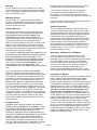
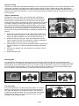
The Receiver
1. Throttle Port: Where the Electronic Speed Control (ESC) plugs in.
2. Steering Port: Where the steering servo(s) plug in.
3. Bind Status LED: Blinking LED signifies binding in process, solid light indicates binding complete.
The Electronic Speed Controller (ESC)
4. On/Off Switch: Powers the receiver and ESC.
5. Setup Button and Indicator Light: Used for re-setting the ESC.
4
5
1
2
6. Battery Lead: Connects to the battery pack for power.
7. Motor Lead: Connects to the wire leads from the motor.
3
7
6
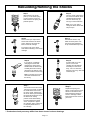
Resetting the ESC
The ESC comes from the factory pre-set and ready for use. If for some reason you should need to re-set the ESC, use
the following instructions.
1. Turn on the transmitter and ESC. Press the set-up button—both the RED and GREEN LEDs will come on.
2. Pull the throttle trigger all the way back (full speed) and press the set-up button once—only the GREEN LED will
come on.
3. Push the throttle trigger full forward (brake/reverse) and push the set-up button once—only the RED LED will
come on.
4. Let the throttle trigger return to the neutral (center) position and press the set-up button once more to save the
program and exit set-up mode—only the GREEN LED will be on.
Notes:
A: If the receiver does not receive a signal from the Transmitter, or if during the bind process, the ESC will not enter
the Program mode.
B: While in Program mode, the motor will not run.
C: If the set-up button is not pressed for 20 seconds while in the Program mode, the ESC will exit the Program mode
and the data will be saved.
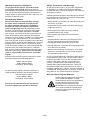
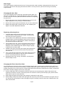
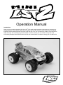
Page The Transmitter
1. Steering Wheel: Controls direction (left/right) of the model.
12
2. Throttle Trigger: Controls speed and direction (forward/
reverse) of the model.
3. Antenna: Transmits signal to the model.
4. On/Off Switch: Turns the power on for the
transmitter operation.
3
10
5. Indicator Lights: Green (top) light indicates adequate battery
power. Red (bottom) light indicates signal strength.
6. Steering Trim (ST. TRIM): Adjusts the “hands off” direction
of the model.
7. Throttle Trim (TH. TRIM): Adjusts the motor speed to stop
at neutral.
9
6
5
8. Steering Rate: Adjusts amount front wheels move when the
steering wheel is turned left or right.
9. Steering Reverse Switch (ST. REV): Reverses the function
of the steering when the wheel is turned left or right.
4
10. Throttle Reverse Switch (TH. REV): Reverses the function
of the speed control when pulled back or pushed forward.
11. Bottom Cover: Covers and holds the batteries powering
the transmitter.
7
2
8
12. Binding LED: The orange LED blinks when the transmitter is
binding to the receiver. A solid light indicates binding process
completed successfully.
1
11
Re-Binding the Transmitter to the Receiver
The Losi DSM radio system included in the Mini-LST2 operates on 2.4 GHz, and provides 79 different channels
which are automatically selected when the transmitter and vehicle are turned on. The communication between the
transmitter and receiver begins in the few seconds after the transmitter and vehicle are both turned on. This is called
the “binding process.” The Losi DSM radio system will not interfere with previous technology radio systems that
operate on 27 MHz or 75 MHz frequencies and you will not receive any interference from them.
Although set at the factory, below are the steps required to re-bind your transmitter to the receiver should the need
arise. During the bind process there is a unique ID from the transmitter communicated to the receiver to ensure
trouble-free radio operation.
Steps to Re-Bind
1. Ensure that the transmitter and vehicle are both turned off.
2. Using the supplied Bind plug (which looks like a standard receiver plug with a wire loop installed) insert or plug
into the receiver slot labeled “BIND”. Looking down on the receiver this slot would be below the LED and is the
farthest from the LED, or nearest to the corner of the receiver.
Note: You do not need to remove any of the other plugs to re-bind.
3. With the Bind plug installed, turn on the vehicle. Notice a blinking Orange LED within the receiver.
4. Now you are ready to turn on the transmitter. You should notice on the back of the transmitter a similar blinking
Orange LED under the translucent cover.
5. Both the receiver and transmitter blinking Orange LED will stop blinking and become solid, indicating they have
“bound” themselves together.
6. Please turn off both the vehicle and transmitter to remove the Bind plug from the receiver. Failing to remove the
Bind plug will cause the transmitter to attempt to re-bind every time you turn on the vehicle and transmitter.
7. Turn on both the vehicle and transmitter to ensure operation. If the transmitter does not control the vehicle, please
repeat steps 1–6. Should this not correct the problem please call Horizon Service/Repair for further assistance.
8. The Bind process is complete. Your vehicle’s radio system should be ready for use.
Page Chassis Tuning
The Mini-LST2 has several adjustments available to you for tuning the performance for your needs. Although there are
multiple shock positions and camber link locations provided. We have built the model with the best overall settings.
The following are simple adjustments and easily maintained settings to assure proper operation and performance. It is
advised, when making any adjustment, you do so in small increments and always check for other parts of the chassis
that are affected.
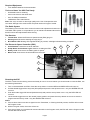
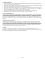
Slipper Adjustments
The slipper is a key component of the drivetrain that is designed to
absorb sudden or large impacts that would otherwise stress various
drivetrain parts. You should never run the Mini-LST2 with the slipper
locked (all the way tight). The slipper can also be used as a tuning device
for extreme conditions. Running the slipper so it slips for a few inches
upon initial acceleration will help the overall drivability of your model. If
the surface is very slick, this will allow the tires to establish some grip
without spinning; in extremely good traction conditions it will help keep
the front tires on the ground and actually provide better acceleration and
steering.
Increase Slip
Reduce Slip
1. Hold the spur gear with your thumb and using the included wrench,
tighten the slipper adjustment nut until relatively tight. Do not try to
torque it as tight as possible—only until you feel it stop turning.
2. While still holding the spur gear, back off the adjustment nut one
full turn (marking one flat on the adjustment nut with a marking pen
makes it easy to see how much the nut has turned).
3. Place the Mini-LST2 on the ground, preferably carpet or asphalt, and
test the acceleration by rolling it backwards and pulling the throttle
trigger.
4. If there is any slippage, turn the adjustment nut clockwise one flat
and retest.
5. Replace the gear cover.
Steering Rate
Your transmitter is equipped with a steering rate control to the left of the steering wheel. This advanced feature,
usually found only on competition-type radios, allows you to adjust the amount the front tires move when you turn the
steering wheel. This is really helpful when you are on slick, as well as high traction, surfaces. If your Mini-LST2 turns
too sharply and/or spins out easily, try turning the steering rate down by rotating the knob counterclockwise (to the
left). For sharper or additional steering, try turning the knob clockwise (to the right).
Less Rate
Full Rate
Toe-In/Toe-Out
This is the relationship of the left and right side tires to one another.
Ideally you want the front of the tires to be pointed inward toward
each other just slightly when viewed from above. This makes the
model track straight and stable. This is controlled with the threaded
steering rods on either side. As you make them longer you will
increase the toe-in and vice versa.
Page Normal
More Toe-In
Ride Height
This is the height the chassis sits and runs at. Turning the shock collar clockwise, looking down from the top, will
increase the pre-load on the spring and raise the chassis. You may want to try this when running on extremely
rough surfaces.
Changing the Spur Gear
If you are changing the size of the spur gear and/or pinion gears, you
will have to loosen the four screws that attach the motors (two screws
on each motor) to the motor plate and follow the directions for adjusting
the gear mesh.
1. Remove the gear cover. Use the included wrench to remove the
slipper adjustment nut by turning it counterclockwise.
2. Remove the old spur gear and install the new one of the same size.
3. Replace the slipper plate, washers and nut. See “Adjusting the
Slipper” for proper adjustment directions.
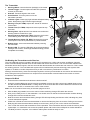
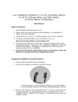
Replacing a Steering Servo
1. Locate and disconnect the servo lead where it plugs in the
receiver harness. There will be two of these, one for the left
servo and one for the right servo.
2. Turn the Mini-LST2 upside-down and with the wheels pointing
straight forward, remove the Phillips screw from the center of
the servo arm (Figure 1). Set the screw, washer and spring to
one side and remove the bell crank.
3. Turn the Mini-LST2 over, remove the small screws at the front
and back of the servo (Figure 2). Carefully remove the servo
feeding the servo lead through the chassis noting the proper
routing for the new servo lead.
4. Install the new servo connecting and routing the wires like the
one you removed. Secure the servo with the screws at the
front and rear.
5. Turn on the radio and remove the servo saver bottom from the
removed servo and install it on the new servo so that the “VGroove” is pointing toward the other servo.
6. Reinstall the bell crank, spring, and washer, securing them
with the Phillips screw.
Changing the Pinion Gear/Gear Ratio
You must always use the same spec of motor and size of pinion gear on both motors in the Mini-LST2. When you
install hotter motors you may find it necessary to install smaller pinion gears to keep them from overheating. This is
usually caused when you are running in a confined area where the motors are not allowed to rev freely. At this point
both motors should be slightly loose on the motor plate.
1. Use the small Allen wrench included to loosen the setscrews in both pinion gears. Slide off the pinions and
replace them with the new size. If the new pinions do not slide on to line up with the spur gear, pull the motors
away from the spur for more clearance.
2. When aligned properly with the spur gear, tighten the setscrew on each pinion.
3. While looking closely at the teeth of the spur gear and one pinion push the motor toward the spur gear until you
can see they are just starting to mesh and slightly snug the mounting screws for that motor. Repeat this for the
other motor as well.
Page Setting the Gear Mesh
1. Insert a small strip of common notebook paper between the pinion and spur gear by feeding it into the gears as
you slowly turn the spur gear with your fingers.
2. Lightly push the motor in toward the spur (if the motor will not move freely, loosen the top screw slightly) until the
pinion is resting solidly against the spur and tighten both mounting screws.
3. Remove the paper and test the mesh by holding your finger against the pinion while trying to rock the spur gear
back and forth. There should be a slight bit of movement before the motor is forced to turn over. If not, loosen the
motor screws slightly and push the motor away from the spur ever so slightly.
4. Retest the mesh and repeat with the other motor making sure all motor screws are tight when done.
5. Replace the gear cover or adjust the slipper if you have also changed the spur gear.
Radio Replacement/Service
If you have a radio problem, please call (877) 504-0233 for customer service. Most likely, unless you have gotten the
components wet, the service technician can help you fix the problem over the phone. If the problem is more severe,
you may be asked to send in the truck and transmitter or the entire radio system, which would include the receiver/
speed control unit and steering servo. In some cases, like a broken servo or a speed control that has failed due to
getting wet, your local dealer can sell you the replacement component. The following is a complete guide to removing
the system.
Receiver/Speed Control (ESC)
Unplug the power lead, motor leads and steering servo. Do not attempt to open the receiver or electronic speed
control (ESC) as only a factory technician has the proper tools and parts to make any repairs necessary. The
receiver and ESC are mounted with double-sided foam tape. Use your thumb and index finger at the bottom of the
front corners to pull them from the mount. If this is difficult, ask for help. If necessary, carefully use a large flat-blade
screwdriver between the unit and the mount to pry it loose. Make sure you remove any leftover foam or adhesive
before remounting with common servo tape or hobby-type foam tape.
Cleaning
Performance can be hindered if dirt gets in any of the moving suspension parts. Use compressed air, a soft
paintbrush, or toothbrush to remove dust or dirt. Avoid using solvents or chemicals as they can actually wash dirt into
the bearings or moving parts as well as cause damage to the electronics.
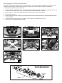
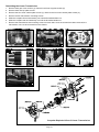
Page Rebuilding the Front and Rear Differential
The gears in the differential will wear over time. The same is true for the outdrives, driveshafts, and rear axles. We
suggest using a small rag or paper towel to lay out the parts you remove to make it easier to reassemble.
1. Remove the upper bumper mount screw.
2. Remove the four chassis screws (1). Loosen the chassis screws (2) enough to allow the bumper to slide out from
under the chassis plate. Note: If you are rebuilding the front differential, skip to Step 6.
3. Remove the four cover screws and remove the cover and remove both screws shown.
4. Remove both screws.
5. Remove both shock tower screws (1). Remove the lower shock mounting screws (2). Remove both differential
cover screws (3).
6. Using a small flat-head screwdriver, carefully pry and remove the differential case cover.
7. Remove the complete differential assembly.
2
1
1
2
3
6
1
3
4
2
5
7
Complete Exploded View of
Front or Rear Differential
Page Rebuilding the Center Transmission
1. Remove both gear cover screws (1). Remove both front top plate screws (2).
2. Remove both rear top plate screws.
3. Remove the four lower chassis plate screws (1). Remove the four lower chassis plate screws (2).
4. Remove all four transmission mounting screws.
5. Slide the complete front end assembly out until the driveshaft slides out.
6. Slide the complete rear end assembly out until the driveshaft slides out.
7. Remove the transmission side-mounting screw from each side. Once the screws have been removed, the
transmission can now be removed from the chassis.
1
1
1
2
2
1
2
3
5
6
4
7
Complete Exploded View of Center Transmission
Page 10
Rebuilding/Refilling the Shocks
Step 1
Step 2
After removing the shock,
push up on the lower spring
cup and remove it from the
shaft. Remove the spring and
preload spacers.
Turn the shock upside down
and remove the black shock
cartridge/shaft assembly
from the shock body by
turning it counterclockwise.
Note: If you only wish to
change or fill the shock fluid,
skip to step 5.
Step 3
Step 4
Remove the top E-clip from the
shock shaft. Remove the shock
piston. Remove second E-clip.
Remove the old cartridge.
Reinstall the lower E-clip.
Slide the shock piston onto
the shock shaft against the
E-clip. Reinstall the top E-clip.
Put a drop of oil on the shock
shaft before installing a new shock
cartridge.
Step 5
If you plan on completely
changing the shock fluid
(suggested), dump out the
old fluid from the shock body.
Carefully fill the shock body
with fluid to the bottom of the
threads inside the shock body.
Step 6
Pull the shaft out so the
piston is next to the
cartridge and reinstall the
assembly into the shock
body, turn in a clockwise
direction until snug—DO NOT
TIGHTEN yet!
Note: Your Mini-LST2 comes
with 30wt shock fluid from
the factory.
Step 7
Turn the shock over and use a
1/16-inch hex wrench to remove
the small bleed screw at the
top of the shock. Slowly push
the shock shaft up until it stops.
Excess fluid should flow out of
the bleed hole. Slowly
pull the shock shaft halfway
back and replace the bleed
screw. Use pliers to tighten
the cartridge, being careful not
to strip the plastic lobes on
the cartridge.
** Production shock parts may differ from those shown in above drawings.
Page 11
Step 8
Replace the spring and
spring cup and test the shock
action for smoothness and
leaks. Retighten the bleed
screw or cartridge if either
leaks. Remount the shock on
your truck.
FCC Information
Shock Assembly
This device complies with part 15 of the FCC rules.
Operation is subject to the following two conditions:
(1) This device may not cause harmful interference,
and (2) this device must accept any interference
received, including interference that may cause
undesired operation.
Caution: Changes or modifications not expressly
approved by Horizon Hobby, Inc. could void the
user’s authority to operate the equipment.
LOSB0963
This product contains a radio transmitter with wireless
technology which has been tested and found to be
compliant with the applicable regulations governing
a radio transmitter in the 2.400GHz to 2.4835GHz
frequency range.
LOSB0963
The following countries associated regulatory agencies
recognizing the noted certifications for this product as
authorized for sale and use are:
LOSB0952
USA
Canada
Belgium
Denmark
France
Finland
Germany
Italy
Netherlands
Spain
Sweden
UK
Ireland
©2007 Losi, an exclusive brand of
Horizon Hobby, Inc.
4105 Fieldstone Rd.
Champaign, IL 61822
Customer Support
1-877-504-0233
www.horizonhobby.com
www.losi.com
10625
Page 12
Australia