1
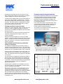
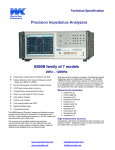
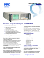
Technical data sheet
Precision Component Analyzers- 6430B & 6440B
•
•
Fast automatic capacitor testing
•
•
•
Fast measurement speed
Comprehensive measurement functions,
Graphical sweep on all measurement functions
In this mode the operator decides which parameter is
to be measured and at what frequencies. The 6430B
and 6440B does the rest, creating an easy to read
table on the large LCD display. Each test can have a
simple Pass/Fail display.
•
•
•
Characterize components to 3 MHz
Measurement parameters
High measurement accuracy on
dissipation factor
0.02% basic measurement accuracy
Large LCD display and intuitive user interface
Unbeatable price
The 6430B and 6440B Precision Component Analyzers
provide thorough and accurate testing of any passive
component to high resolution.
In particular, for capacitor manufacturers, the instruments
provide capabilities for both fast automatic production
testing and complete design characterisation.
Users include designers of passive components,
manufacturing test, designing and testing materials as well
as circuit designers who are evaluating component
characteristics.
The resonant frequency can be automatically calculated
for any component together with its equivalent series or
parallel circuit at that frequency.
Both instruments are designed for high performance
testing of components, with a basic accuracy of 0.02%, at
a low price. 6430B is the entry level instrument covering to
500 kHz whilst the fully featured 6440B covers to 3 MHz.
www.waynekerrtest.com
To evaluate a component performance at high speed
over a specified range of frequencies, multi frequency
mode is used.
•
•
•
•
•
•
•
•
•
•
•
•
Impedance (Z)
Phase Angle (Ø)
Inductance (L)
Capacitance (C)
DC Resistance (Rdc)
AC Resistance (Rac)
Quality Factor (Q)
Dissipation Factor (D)
Admittance (Y)
Conductance (G)
Reactance (X)
Susceptance (B)
Graphical sweep on all measurement
functions up to 3 MHz
To characterize a component graphically the user can
select any of the available measurement functions and
create a graph of the parameter value against
frequency or AC drive level.
The user is also able to toggle between the major and
minor term, for example impedance and phase angle.
Either linear or logarithmic scales can be selected.
[email protected]
Technical data sheet
Following the first sweep the user can use the FIT key,
which automatically scales the vertical axis to provide the
optimum display for the device under test (DUT).
A marker is also displayed which can be positioned at any
point on the graph using the navigation keys. The MAX
and MIN keys position the marker at the peak or trough of
the graph. The marker position is displayed at the bottom
of the screen showing the vertical axis value, its minor
term and the frequency or drive level.
Printing results and external control
Whether it’s a single parameter, table of results from multi
frequency mode or a logarithmic graph of component
performance, the 6430B and 6440B will output the results
directly to a printer.
Protection against charged capacitors
High precision measuring instruments can be sensitive
to charged capacitors and if connected can lead to
costly repairs and unacceptable downtime. Wayne
Kerr Electronics have identified this problem and
developed a solution that protects the test equipment
from charged capacitors.
In this event, the protection unit blows fuses, which
can be easily and cheaply replaced, whilst the test
equipment remains unharmed and continues to
provide reliable accurate performance.
The protection unit will protect the test equipment from
up to 25 Joules of charged energy.
The GPIB interface is used to control the instrument and
read back measured values for quality control or for
archiving purposes.
Output lines are also available to control a bin handler
interface. Component tolerance levels may be pre-set and
stored. A 25-way D connector mounted on the rear panel
gives easy access for connection to external component
handling equipment.
Fast automatic multi-frequency production
testing of capacitors
The 6430B and 6440B deliver fast automatic testing of
capacitors in a production environment. The user is able
to select measurements from any of the instruments range
and perform up to eight different tests on each component.
Tolerance bins can be selected for each of the tests. The
instrument selects the overall bin after completing all the
tests. The measured results can be output over the GPIB
or to a printer.
Accurate component analysis to 500 kHz (6430B) or
3 MHz (6440B) is simplified by many accessories
which includes Overload Protection Unit 1J1100
The test sequence is triggered by external input, GPIB or
the front panel. Once the test sequence is complete the
bin is selected and the measured data is made available
on the GPIB. This process takes place at very high speed
allowing a dual frequency test to be completed in
approximately 180 ms.
Pass/Fail data in statistical form is available to the user
and can be viewed on the LCD display, printed to a local
printer or exported over the GPIB.
Excellent performance and unbeatable price
As the market leader with over 50 years experience of
developing component analyzers you would expect Wayne
Kerr to provide the best performance in the industry.
However, what you might not also expect is that Wayne
Kerr is able to offer high performance and accuracy at very
competitive prices.
www.waynekerrtest.com
Inductance plotted against frequency
[email protected]
Technical data sheet
Technical specifications, precision
component analyzers - 6430B & 6440B
Rdc ± 0.1%
Accuracy varies with component range measurement speed
and frequency
Measurement parameters
Modes of operation
Any of the following parameters can be measured and displayed:
Inductance (L), impedance (Z), DC resistance (Rdc) and
capacitance (C)
Series or Parallel Equivalent Circuit
C+R, C+D, C+Q, L+R, L+Q
Series equivalent circuit only
X+R, X+D, X+Q
Parallel equivalent circuit only
C+G, B+G, B+D, B+Q
Polar Form
Z + Phase Angle, Y + Phase Angle
Measurement
Test conditions
Measurement parameters and test conditions set using
measurement mode
Up to 8 frequencies with absolute or percentage limits on
major term Pass/Fail indication
Frequency range 6430B
20 Hz to 500 kHz >1000 steps
Accuracy of set frequency ±0.005%
>1500 steps with analysis option fitted
Frequency range 6440B
20 Hz to 3 MHz > 1800 steps
Accuracy of set frequency ±0.005%
Pre-set frequencies
20, 25, 30, 40, 50, 60, 80, 100, 120,
150 repeats for each decade
Drive level (Rdc)
100 mV or 1 V with 100 Ω source resistance
Drive level (AC measurements)
Open circuit voltage 1 mV to 10 V rms
Signal source impedance 50 Ω
Automatic Level Control (ALC) maintains constant voltage or
current at DUT
DC bias voltage (internal)
2 V with rapid charge capacitor bias
DC bias voltage (external)
External supply of up to ±60 V may be connected via rear panel
Measurement speeds
Four selectable speeds for all measurement
functions Up to 20 measurements per
second for test frequencies ≥100 Hz
Measurement ranges
R, Z 0.01 mΩ to > 2 GΩ
G, Y 1 nS to > 2 kS
L 0.1 nH to > 2 kH
C 1 fF to > 1 F
D 0.00001 to >1000
Q 0.00001 to >1000
Rdc 0.1 mΩ to > 10 MΩ
Selection of any measurement parameter and test condition
Single level function menu controlled by keyboard and soft
keys
Single and repetitive measurements displaying major and
minor terms
Deviation
As measurement mode but relative or percentage deviation
from nominal value displayed for major or minor term
Multi-frequency
Multi-frequency capacitor (optional)
Test condition set using measurement mode.
Up to 8 frequencies with different measurement parameters.
Binning result in up to 10 bins with percentage limits on major
term and absolute on minor. Fast mode up to twice the speed
of standard multi-frequency mode.
Analysis mode (optional 6430B)
Measurements parameters and test conditions set using
measurement mode
Graphical sweep vs. frequency or level with selection of start,
step size, units and linear/log.
Binning (optional)
Measurement parameters and test conditions set using
measurement mode.
10 bins with absolute and percentage limits.
Up to 99 sets of limits may be saved.
25 way D-type interface connector.
Option /B1 (non-isolated)
Common 0 V. Bin outputs 0 to 5 V(nominal) with >10 mA
current sink capability.
Option /B2 (isolated)
Common 24 V input. Outputs 0 to 24 V with >10 mA current
source capability.
Measurement connections
4 front panel BNC sockets
4-wire (Kelvin) measurements with screen at ground potential
General
Power requirements
115 V or 230 V AC ±10% (selectable)
150 VA Max
Mains frequency
Basic accuracy
50/60 Hz
L/C ±0.05%
R ±0.02%
Q ± 0.05 %(Q + 1/Q)
D ±0.0002(1+ D2)
Mains fuse rating
230 V operation - 1A ’T’ type
115 V operation – 2A ’T’ type
www.waynekerrtest.com
[email protected]
Technical data sheet
Display
Order codes
High contrast monochrome LCD module
320 x 240 with back lighting
Visible area 115 x 86 mm
Viewing angle 45°
Printer output
Centronics / parallel printer port
Description
Order code
6430B Precision Component Analyzer
(20 Hz to 500 kHz)
6440B Precision Component Analyzer
(20 Hz to 3 MHz)
1J6430B
1J6440B
Both models supplied with:User manual
2m AC power cable
Kelvin clips 1EVA40100
Remote control
Conforms with GPIB-IEEE 488.2 and
SCPI 1992.0
6440B supplied with:2 x transfer standard capacitors
Mechanical
Height 150 mm (5.9″)
Width 440 mm (17.37″)
Depth 525 mm (20.5″)
Weight 11 kg (24.25 lb)
Options for 6430B
/B1 Bin handler (cannot be fitted with /B2)
/B2 Bin handler opto-coupled (cannot be fitted with /B1)
/C Multi-frequency capacitor function
/E Analysis function (standard on 6440B)
Environmental conditions
Temperature Range
Options for 6440B
Storage -40°C to 70°C
Operating 0°C to 40°C
Full Accuracy 15°C to 35°C
/B1 Bin handler (cannot be fitted with /B2)
/B2 Bin handler opto-coupled (cannot be fitted with /B1)
/C Multi-frequency capacitor function
Relative humidity
Up to 80% non-condensing
Optional accessories for 6430B & 6440B
Altitude
Up to 2000m
Installation category
II in accordance with IEC664
Pollution degree
2 - mainly non-conductive
This equipment is intended for indoor use only in a non-explosive
and non-corrosive atmosphere
Safety
Complies with the requirements of EN61010-1
Description
Order code
Overload Protection Unit (25 Joules)
Kelvin Lead (large jaw)
Kelvin Lead (fine jaw)
4 Terminal Lead Set
BNC-4 Term. Comp. Fixture
BNC-4 Term. Comp. Fixture (>500 kHz)
SMD Probe Lead
SMD Tweezers
Operating/Maintenance Manual
Certificate of Calibration with results
1J1100
1EVA40180
1EVA40100
1EV1505
1EV1005
1EV1006
1EV1905A
1EVA40120
9H(model no.)
1JCALRES
EMC
Complies with EN61326 for emissions and immunity
UK
USA
Wayne Kerr Electronics
Vinnetrow Business Park
Vinnetrow Road, Runcton
Chichester, West Sussex
PO20 1QH, UK
Tel: +44 1243 792200
Fax: +44 1243 792201
Wayne Kerr Electronics
165L New Boston Street
Woburn
MA 01801-6201 USA
Tel: +1 781 938 8390
Sales: (800) 933 9319
Fax: +1 781 933 9523
Wayne Kerr’s policy is one of continuous development and consequently the product may vary in detail from the description and specification in this publication.
www.waynekerrtest.com
[email protected]
GMS0904A