1
Troubleshooting Guide
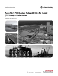
PowerFlex 7000 Medium Voltage AC Drives
Publication 7000-TG002J-EN-P
Important User Information
Read this document and the documents listed in the additional resources section about installation, configuration, and
operation of this equipment before you install, configure, operate, or maintain this product. Users are required to
familiarize themselves with installation and wiring instructions in addition to requirements of all applicable codes, laws,
and standards.
Activities including installation, adjustments, putting into service, use, assembly, disassembly, and maintenance are required
to be carried out by suitably trained personnel in accordance with applicable code of practice.
If this equipment is used in a manner not specified by the manufacturer, the protection provided by the equipment may be
impaired.
In no event will Rockwell Automation, Inc. be responsible or liable for indirect or consequential damages resulting from the
use or application of this equipment.
The examples and diagrams in this manual are included solely for illustrative purposes. Because of the many variables and
requirements associated with any particular installation, Rockwell Automation, Inc. cannot assume responsibility or
liability for actual use based on the examples and diagrams.
No patent liability is assumed by Rockwell Automation, Inc. with respect to use of information, circuits, equipment, or
software described in this manual.
Reproduction of the contents of this manual, in whole or in part, without written permission of Rockwell Automation,
Inc., is prohibited.
Throughout this manual, when necessary, we use notes to make you aware of safety considerations.
WARNING: Identifies information about practices or circumstances that can cause an explosion in a hazardous environment,
which may lead to personal injury or death, property damage, or economic loss.
ATTENTION: Identifies information about practices or circumstances that can lead to personal injury or death, property
damage, or economic loss. Attentions help you identify a hazard, avoid a hazard, and recognize the consequence.
IMPORTANT
Identifies information that is critical for successful application and understanding of the product.
Labels may also be on or inside the equipment to provide specific precautions.
SHOCK HAZARD: Labels may be on or inside the equipment, for example, a drive or motor, to alert people that dangerous
voltage may be present.
BURN HAZARD: Labels may be on or inside the equipment, for example, a drive or motor, to alert people that surfaces may
reach dangerous temperatures.
ARC FLASH HAZARD: Labels may be on or inside the equipment, for example, a motor control center, to alert people to
potential Arc Flash. Arc Flash will cause severe injury or death. Wear proper Personal Protective Equipment (PPE). Follow ALL
Regulatory requirements for safe work practices and for Personal Protective Equipment (PPE).
Allen-Bradley, Rockwell Software, Rockwell Automation, and TechConnect are trademarks of Rockwell Automation, Inc.
Trademarks not belonging to Rockwell Automation are property of their respective companies.
Summary of Changes
This manual contains new and updated information.
New and Updated
Information
This table contains the changes made to this revision.
Topic
Page
Added Fault 159
21
Updated STO Gating Flt description
40
Rockwell Automation Publication 7000-TG002J-EN-P - March 2015
3
Summary of Changes
Notes:
4
Rockwell Automation Publication 7000-TG002J-EN-P - March 2015
Table of Contents
Preface
About this Publication . . . . . . . . . . . . . . . . . . . . . . . . . . . . . . . . . . . . . . . . . . . . . 7
Who Should Use This Manual . . . . . . . . . . . . . . . . . . . . . . . . . . . . . . . . . . . . . . 7
Additional Resources . . . . . . . . . . . . . . . . . . . . . . . . . . . . . . . . . . . . . . . . . . . . . . . 7
Acronyms and Abbreviations. . . . . . . . . . . . . . . . . . . . . . . . . . . . . . . . . . . . . . . . 8
Chapter 1
Fault Messages
Overview . . . . . . . . . . . . . . . . . . . . . . . . . . . . . . . . . . . . . . . . . . . . . . . . . . . . . . . . 11
Fault Messages . . . . . . . . . . . . . . . . . . . . . . . . . . . . . . . . . . . . . . . . . . . . . . . . . . . 12
Chapter 2
Warning Messages
Overview . . . . . . . . . . . . . . . . . . . . . . . . . . . . . . . . . . . . . . . . . . . . . . . . . . . . . . . . 55
Warning Messages . . . . . . . . . . . . . . . . . . . . . . . . . . . . . . . . . . . . . . . . . . . . . . . 56
Appendix A
Spare Parts
Components and Related Part Numbers . . . . . . . . . . . . . . . . . . . . . . . . . . . 87
Appendix B
Fault Codes
Listed Numerically . . . . . . . . . . . . . . . . . . . . . . . . . . . . . . . . . . . . . . . . . . . . . . . 89
Appendix C
Warning Codes
Listed Numerically . . . . . . . . . . . . . . . . . . . . . . . . . . . . . . . . . . . . . . . . . . . . . . 107
Rockwell Automation Publication 7000-TG002J-EN-P - March 2015
5
Table of Contents
Notes:
6
Rockwell Automation Publication 7000-TG002J-EN-P - March 2015
Preface
About this Publication
This manual contains troubleshooting information for medium voltage
PowerFlex® 7000 drives only.
Who Should Use This Manual
This manual is intended for qualified service personnel responsible for
troubleshooting and repairing medium voltage PowerFlex 7000 drives. You
should have previous experience with, and basic understanding of, electrical
terminology, procedures, required troubleshooting equipment, equipment
protection procedures and methods, and safety precautions.
Additional Resources
These documents contain additional information concerning related products
from Rockwell Automation.
Resource
Description
Publication 7000-IN006
PowerFlex 7000 Medium Voltage AC Drive (B Frame) Commissioning - ForGe Control
Publication 7000-IN007
PowerFlex 7000 Medium Voltage AC Drive (B Frame) Installation - ForGe Control
Publication 7000-IN008
PowerFlex 7000 Medium Voltage AC Drive (B Frame) Trans. & Handling - ForGe Control
Publication 7000-IN010
Handling, Inspection, and Storage of Medium Voltage Line Filter Capacitors
Publication 7000-PP002
PowerFlex 7000 Air-Cooled Drives
Publication 7000-QS002
HMI Interface Board Software Updater and Firmware Download Procedure
Publication 7000-TD001
PowerFlex 7000 Medium Voltage AC Drive (Firmware Version 6.xxx) - Classic Control
Publication 7000-TD002
PowerFlex 7000 Medium Voltage AC Drive (Firmware Version 9.xxx) - ForGe Control
Publication 7000-UM150
PowerFlex 7000 Medium Voltage AC Drive (B Frame) - Classic Control
Publication 7000-UM151
PowerFlex 7000 Medium Voltage AC Drive (B Frame) - ForGe Control (Using
PanelView 500)
Publication 7000-UM201
PowerFlex 7000 HMI Offering with Enhanced Functionality
Publication 7000-UM202
PowerFlex 7000 Medium Voltage AC Drive (B Frame) - ForGe Control
Publication 7000-UM203
PowerFlex 7000 Series Safe Torque Off
Publication 7000A-UM150 PowerFlex 7000 Medium Voltage AC Drive (A Frame) - Classic Control
Publication 7000A-UM151 PowerFlex 7000 Medium Voltage AC Drive (A Frame) - ForGe Control (Using
PanelView 550)
Publication 7000L-UM301
PowerFlex 7000 Medium Voltage AC Drive (C Frame) - ForGe Control
Publication 7000L-UM302
PowerFlex 7000 Medium Voltage AC Drive (C Frame) - ForGe Control (Marine)
You can view or download publications at
http:/www.rockwellautomation.com/literature/. To order paper copies of
technical documentation, contact your local Allen-Bradley distributor or
Rockwell Automation sales representative.
Rockwell Automation Publication 7000-TG002J-EN-P - March 2015
7
Preface
Acronyms and Abbreviations
8
Acronym/ Abbreviation
Description
A/D
Analog/Digital
A2D
Analog to Digital
AC
Alternating Current
ACB
Analog Control Board
Accel
Acceleration
ADC
Analog to Digital Converter
Anlg
Analog
BW
Bandwidth
Cap
Capacitor
Ch
Channel
Chn
Channel
CIB
Customer Interface Board
CMC
Common Mode Choke
Cmd
Command
Conv
Converter
CT
Current Transformer
Ctctr
Contactor
Cur
Current
DAC
Digital to Analog Converter
DB
Dynamic Braking
DC
Direct Current
DCB
Drive Control Board
DCSL
Drive Control and Synchronization Link
DD
Dimensional Drawings
Decel
Deceleration
DIM
Drive Identity Module
Dly
Delay
DO
Drive Output
DPI
Drive Peripheral Interface
DPM
Drive Processor Module
DrvIn
Drive Input
ED
Electrical Drawings
ESP
Electric Submersible Pump
Fbk
Feedback
Flt
Fault
Fltr
Filter
FO
Fiber-Optic
FOB
Fiber-Optic Interface Board
FOI
Fiber-Optic Interface
FPGA
Field-Programmable Gate Array
Rockwell Automation Publication 7000-TG002J-EN-P - March 2015
Preface
Acronym/ Abbreviation
Description
Freq
Frequency
GND
Ground
Gnrl
General
HECS
Hall Effect Current Sensor
Hi
High
HP
Horse Power
HW
Hardware
I
Current
IGDPS
Isolated Gate Driver Power Supply
Init
Initialize
Inv
Inverter
IO
Input/Output
Isoltn Sw
Isolation Switch
L
Inductance
L
Line
LED
Light-emitting diode
Liq
Liquid
Lo
Low
LR
Line Reactor
LV
Low Voltage
M
Machine
Magntz
Magnetizing
Max
Maximum
Min
Minimum
Mstr
Master
MTR
Motor
NVRAM
Non-Volatile Random Access Memory
OC
Overcurrent
OL
Overload
OP
Output
OT
Overtemperature
OV
Overvoltage
PD
Parallel Drive
PF
Power Factor
PFC
Power Factor Correction
PID
Proportional, Integral, Derivative (process control)
PLC
Programmable Logic Control
PSD
Power Structure Diagnostic
PWM
Pulse-Width Modulation
Rect
Rectifier
Rockwell Automation Publication 7000-TG002J-EN-P - March 2015
9
Preface
10
Acronym/ Abbreviation
Description
Rot’n
Rotation
SCB
Signal Conditioning Board
SCR
Silicon-Controlled Rectifier
SGCT
Symmetrical-Gate Commutated Thyristor
Slv
Slave
Spd
Speed
SPGD
Self-Powered Gate Driver
STO
Safe Torque Off
SW
Software
Sync
Synchronous
Tach
Tachometer
TFB
Temperature Feedback Board
TFB3
Temperature Feedback Board, 3rd generation
Trp
Trip
Trq
Torque
TSN
Transient Suppression Network
UB
Unbalance
UPS
Uninterrupted Power Supply
USART
Universal Synchronous/Asynchronous Transmitter/Receiver
V
Volt
VSB
Volt Sensing Board
Wrn
Warning
Xfer
Transfer
XIO
External Input/Output
Rockwell Automation Publication 7000-TG002J-EN-P - March 2015
Chapter
1
Fault Messages
Overview
All faults, warnings, or messages displayed on the operator interface should be
thoroughly documented by the user prior to resetting those messages. This will
assist maintenance personnel in correcting problems and ensuring they do not
recur.
ATTENTION: Investigate all faults before resetting the drive.
Resetting the drive into a fault condition that has been unresolved can
propagate the faults and cause an increased level of damage to the equipment.
Rockwell Automation Publication 7000-TG002J-EN-P - March 2015
11
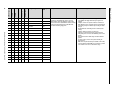
X
AC/DC#2 AC Fail
59
X
AC/DC#3 AC Fail
60
There can be up to 4 AC/DC power supplies in a drive,
designated 1, 2, 3 and 4. Each power supply will have its input
control voltage measured and monitored for reliable drive
operation. An AC Fail is detected when the input to any of the
AC/DC power supplies goes below 85Vrms.
X
AC/DC#4 AC Fail
61
• Verify the input AC voltage to the power supply, typically 110Vac or 120Vac.
• Be sure that the AC/DC power supply monitor signal is connected to the ACB.
• Check the Metering group in the drive variables to view the control power value the drive
is measuring.
• The example below shows that the drive is detecting a single AC/DC power supply whose
input voltage is 116.6V.
Heat pipe Drive
58
Marine Drive
AC/DC#1 AC Fail
PF7000C
X
PF7000B
Recommended Action(s)
PF7000A
Description
All Drive Types
Fault Code
Rockwell Automation Publication 7000-TG002J-EN-P - March 2015
120Vac is measured directly on the ACB at terminals J1 14-15.
The drive displays the measured value in the Metering group
parameters 118, 77, 79, and 92 for power supplies 1 to 4
respectively.
X
AC/DC#1 DC Fail
48
X
AC/DC#2 DC Fail
49
X
AC/DC#3 DC Fail
50
X
AC/DC#4 DC Fail
51
X
Adapter 1 Loss
17
X
Adapter 2 Loss
18
X
Adapter 3 Loss
19
X
Adapter 4 Loss
20
X
Adapter 5 Loss
21
X
Adapter 6 Loss
22
There can be up to 4 AC/DC power supplies in a drive,
designated 1, 2, 3 and 4. Each power supply has its own
sensing circuit and will monitor its DC output voltage. The
AC/DC power supply triggers a DC Fail signal when an output
drops below 49Vdc.
The drive monitors the DC Fail signals from the inputs
connected to terminals J18, J19, J20 and J21.
The drive monitors the 56VDC supply via connection J15 1-2
on the ACB.
• Verify that the power supply is energized and is using the appropriate input control power.
• Measure the output voltage and confirm whether the output level is below the trip level.
• Verify that the fault detection wiring is per the drawings, and measure the voltage on the
trip signals. For example, Terminal J18 2-3 is 5Vdc when healthy, and 0V in a faulted state.
• Verify that the power supply internal cooling fan is operational, cycle control power if
needed.
• If the cooling fan is not operational, replace the power supply.
• Check parameter 121 in the Metering group of the drive variables to view the measured
DC voltage.
There has been a loss of communication between the Drive
Processor Module (DPM) and the DPI adapter 1-6.
• Cycle control power to the drive.
• Change the adapter and/or DPM if all attempts to restore communication fail.
• Ensure that the adapter is plugged into the ACB, powered, and working properly.
Fault Messages
Fault Message
Chapter 1
12
Fault Messages
26
X
Adaptr2 ForceFlt
27
X
Adaptr3 ForceFlt
28
•
•
•
•
X
Adaptr4 ForceFlt
29
There has been a loss of communication between the
identified DPI adapter and the customer’s communication
network. The communication between the drive and the DPI
adapter may still be active. This is a requirement for DPI
communications. If the loss of communication from the
network to the adapter is required to be a warning, this must
be set in the adapter itself, not within the drive.
X
Adaptr5 ForceFlt
30
X
Adaptr6 ForceFlt
31
Ambient OvrTemp
182
NOT ACTIVE
Ambient LowTemp
183
NOT ACTIVE
Ambient FbrOptic
184
NOT ACTIVE
Ambient Sensor
185
NOT ACTIVE
X
Arbitration Loss
602
The number of Arbitration Loss faults has exceeded the
maximum allowable level.
• Check the DCSL communication wiring and shielding.
X
Auxiliary Prot’n
37
Standard External Fault/Warning Input included to allow the
end user to install a protective relay/system status contact
that can activate a drive fault or warning, depending on
configuration of Aux Prot Class (P445). The message means
that the drive has detected a fault triggered by the input
wired in the auxiliary input of the XIO card.
• Check the device responsible for the auxiliary contact to this input, and investigate the
cause of the open contact status.
• Check the 120V signal through the external device.
• Check the XIO board inputs and parameter status bits.
• Check the 120V wiring and the XIO card.
X
Bypass CtctrOpen
168
The bypass contactor was opened without a command from
the drive. Verify the contactor feedback and the 120V wiring
to the ACB.
• Because the drive system needs to have complete control over all contactors, investigation
of the specific contactor fault is required.
• Verify contactor feedback.
• Verify the control power circuit for the contactor.
• Check permissive string to the contactor control relay (refer to drawing).
• Check contactor/breaker for physical malfunction (auxiliaries).
• Check ACB inputs and outputs at J1.
X
Bypass IsoSwClsd
175
The bypass isolation switch is closed when it was expected to
be open. Verify the isolation switch mechanical set up and the
120V wiring to the ACB. Depending on the operating mode of
the drive, ensure that the switch is in the proper position.
X
Bypass IsoSwOpen
172
The bypass isolation switch is open when it was expected to
be closed. Verify the isolation switch mechanical set up and
the 120V wiring to the ACB. Depending on the operating
mode of the drive, ensure that the switch is in the proper
position.
• Depending on the mode of operation (Normal, System Test, Open-Circuit Test, DC Current
Test, or Open-Loop), there are specific states for all the possible system isolation switches
(Refer to the description of parameter 141 Hardware Options1. Be sure the isolation switches
are in the proper position.
• Verify wiring feedback.
• Verify isolation switch mechanical auxiliary setup.
• READ ASSOCIATED DESCRIPTION.
Heat pipe Drive
Adaptr1 ForceFlt
Marine Drive
X
PF7000C
Recommended Action(s)
PF7000B
Description
PF7000A
Fault Code
All Drive Types
Fault Message
Verify the customer network is properly communicating with the device.
Check DPM status LEDs and compare to the information in the User Manual.
Change the adapter if all attempts to restore communication fail.
Cycle control power.
Rockwell Automation Publication 7000-TG002J-EN-P - March 2015
Fault Messages
Chapter 1
13
Marine Drive
Recommended Action(s)
CabinetTemp High
(C-Frame Only)
70
The drive has a temperature switch in several cabinets, and all
the N/C switches are connected in series and fed back to the
XIO input. The levels are set differently for different cabinets.
•
•
•
•
Capability Limit
465
The motor current exceeded maximum allowable level for the
variable torque drive. Drive was limiting the motor current to
the safe level for drive thermal protection, but new speed
operating point cannot be achieved higher than 6 Hz.
• Ensure that the drive is not used for constant torque load condition.
X
CMC Blcked Exhst
477
There is possibly blockage to the CMC exhaust/inlet airflow.
Note: This fault word is used exclusively on Heatpipe drives.
• Ensure that there are no obstructions to the path of the outgoing/incoming air flow.
• Check for cooling fan deterioration.
• Verify if the trip setting (P813/P814) matched factory recommended value.
X
CMC Blcked Inlet
480
There is possibly blockage to the CMC exhaust/inlet airflow.
Note: This fault word is used exclusively on Heatpipe drives.
• Ensure that there are no obstructions to the path of the outgoing/incoming air flow.
• Check for cooling fan deterioration.
• Verify if the trip setting (P813/P814) matched factory recommended value.
X
CMC Double Fans
474
The drive has just lost two or more of the cooling fans.
• Verify the fan contactors, fan overload and the 120V wiring to the XIO card.
X
Cnv Airflow Loss
505
The cooling airflow velocity on the specified power stack is
below the trip/warn level.
• Ensure that there are no obstructions to the path of the outgoing/incoming air flow.
• Check for cooling fan deterioration. Verify if the trip (P840) and warn setting (P841)
matched factory recommended values.
X
Cnv Double Fans
473
The drive has just lost two or more of the cooling fans.
• Verify the fan contactors, fan overload and the 120V wiring to the XIO card.
X
CMC Fan9 Ctctr
487
Loss of the cooling fan.
• Verify the fan contactor, fan overload and the 120V wiring to the XIO card.
X
Cnv Fan3 Ctctr
482
X
Cnv Fan4 Ctctr
483
X
Cnv Fan5 Ctctr
484
X
Cnv Fan6 Ctctr
485
X
Cnv Fan7 Ctctr
486
Control Pwr Loss
57
There has been a loss or dip in the control power feeding the
drive for more than 5 cycles.
• Ensure that the power source is active and investigate the reliability of the source.
• Check control power input to ACB.
Heat pipe Drive
PF7000C
PF7000B
PF7000A
All Drive Types
Description
X
Rockwell Automation Publication 7000-TG002J-EN-P - March 2015
X
Identify which switch has opened, and focus on that cabinet.
Check for proper air flow within the identified section.
Verify that the stirring fans are operating correctly.
Verify that the ambient temperature is within tolerances.
Fault Messages
X
Fault Code
Chapter 1
14
X
Fault Message
Heat pipe Drive
The air pressure drop at the input to the converter section
sensed by the pressure transducer (as a voltage) has dropped
below the value set in AirLoPresure Trp (P319). This is
dependent on the operation of the main cooling fan.
Components to check are cooling fan, air pressure transducer,
analog control board, blocked air filters, correct parameter
settings.
• Verify fan rotation, necessary air pressure is developed only with the correct direction of
fan rotation.
• Check for blocked airflow in the filters/heatsinks/ducting (if installed). Clean as necessary.
• Improper Trip settings – Verify pressure value voltage level when running with clear air flow,
and compare to expected values for that specific drive type.
• Verify the alarm and trip set-up procedure was completed adequately during
commissioning and adjust as necessary; applicable parameters are:
– Air Pressure Nom (P317)
– AirLoPresure Wrn (320)
– AirLoPresure Trp (319)
• Check that the pressure sensor is working and is connected to the ACB at J9. Control Voltage
for the pressure transducer is +15V on J9 terminals 1 to 3
• Confirm output of the transducer is stable, J9 terminal 2 to 3
• Verify for drives with external ducting that there is sufficient air to the drive input.
• Applicable Tech Notes:
– PowerFlex 7000-Gen-11 PowerFlex 7000 Air Pressure Sensor Setup
– PowerFlex 7000_4Gen_Gen-16 How to Configure Differential Pressure Transducer
– PowerFlex 7000-4Gen_Gen-23 High Air Pressure Fault When Upgrading Firmware to
Rev 8 or Higher
ConductivityHigh
(C-Frame Only)
OIBBS
68
The measured coolant conductivity is greater than 2 μS/cm3.
• Verify that no foreign debris has entered the system (iron piping, non-deionized water,
etc.).
• Wash the mesh filters.
• Change the de-ionizing cartridge and run the system, verifying that the conductivity is
decreasing.
• If the cooling pumps have not been running for a period of time, the conductivity level will
increase. Anticipate this and run the cooling pumps to reduce the conductivity level before
starting
X
Config Fault Inv
629
Inverter configuration fault: A functional safety hardware /
configuration mismatch was detected. There is a hardware
configuration fault on the inverter side.
• If the drive uses the STO feature, ensure no SPS jumper is installed on the inverter OIBBS.
• Verify the drive settings. If the drive uses the STO feature, enable STO.
• Verify the inverter OIBBS (for STO drive) or OIBB (for non-STO drive). In case of incorrect
part(s), contact the manufacturer for replacement spare parts.
X
Config Fault Rec
625
Rectifier configuration fault: A functional safety hardware /
configuration mismatch was detected. There is a hardware
configuration fault on the rectifier side.
• If the drive uses STO feature, the SPS jumper on the rectifier OIBBS must be set correctly.
See parameter 274.
• Verify the drive settings. If the drive uses the STO feature, enable STO.
• Verify the rectifier OIBBS (for STO drive) or OIBB (for non-STO drive). In case of incorrect
part(s), contact the manufacturer for replacement spare parts.
X
Config Fault1
616
Configuration Fault 1: This bit indicates that a configuration
conflict has been detected. The Safe Torque Off function is
incompatible with the following features: N+1, Parallel
Drives, 18-Pulse rectifiers.
• See parameters P141 for redundant devices, P153 for rectifier type, and P717 and P745 for
parallel drives.
• Verify the drive settings and disable the un-supported features.
• Cycle the control power.
X
Config Fault2
617
Configuration Fault 2: This bit indicates that a configuration
conflict has been detected. The Safe Torque Off function is
incompatible with drives utilizing a bypass contactor
including synchronous transfer.
• See parameters P99 for sync transfer enabled and P141 for bypass contactor
configuration.
• Verify the drive settings and disable the un-supported features.
• Cycle the control power.
X
Rockwell Automation Publication 7000-TG002J-EN-P - March 2015
X
Marine Drive
176
X
PF7000C
Convrtr Air Flow
PF7000B
X
PF7000A
Recommended Action(s)
All Drive Types
Description
X
15
Chapter 1
Fault Code
Fault Messages
Fault Message
• Check connections, test the rail voltage level and test for shorts.
• Replace the DC/DC converter if this problem remains.
X
Control 15V Loss
55
There has been a loss of the 15 volt DC rail from the DC/DC
converter.
• Check connections, test the rail voltage level and test for shorts.
• Replace the DC/DC converter if this problem remains.
X
Control 56V Loss
52
The drive has detected a loss of the 56V dc voltage feeding the
DC/DC converter.
• Check the connections, feedback wiring on J14 of the ACB, the DC output of the AC/DC
converter and the input voltage to the DC/DC converter.
• Replace the power supply if required.
X
Heat pipe Drive
There is a single DC/DC power in each drive. It receives 56VDC
input and produces various levels of DC voltages on the
output. One of these output voltage level is 5Vdc. It is a critical
voltage level for the drive processors. This fault message
indicates the 5Vdc produced by the DC/DC power supply has
failed. The drive monitors the 5Vdc by measuring this
voltage.The 5Vdc is connected to the ACB terminal JX 1-2.
Marine Drive
54
PF7000C
Control 5V Loss
PF7000B
X
PF7000A
Recommended Action(s)
All Drive Types
Description
X
X
CoolantLevel Low
(C-Frame Only)
69
The measured coolant level within the reservoir has dropped
below the second (lowest) level sensor and the drive has
faulted. This sensor is set for the minimum level required to
ensure there will be no air drawn into the system through the
reservoir.
• Verify that the drive cooling system does not have any coolant leaks – repair if found.
• Add the proper amount of de-ionized water to get the level above the warning sensor (deionized water will evaporate, not the glycol).
X
X
CoolantTemp High
(C-Frame Only)
67
The measured coolant temperature has exceeded 54 °C
(129 °F). The drive detected that the coolant temperature has
exceeded the trip setting in P483. Ensure that the heat
exchanger fans are working properly and the room ambient is
adequate for the drive operation.
•
•
•
•
X
X
CoolantTemp Low
(C-Frame Only)
66
The measured coolant temperature has dropped below 4 °C
(40 °F). It will not clear until the coolant temperature reaches
10 °C (50 °F). This fault will only occur if the drive is not
running, to stop you from starting with a low coolant
temperature. If you are already running when the coolant
level drops, you will only get a warning.
• Verify that the thermostatic bypass valve (V10) was not left open.
• Verify that the ambient temperature within the drive control room is not below
specification.
• Warm up the control room ambient to get the drive to an operational level.
CRC Fault
601
The number of Cyclic Redundancy Check (CRC) faults has
exceeded the maximum allowable level.
• Check the DCSL communication wiring and shielding.
Verify the heat exchanger fans are operating.
Verify that the thermostatic valve is fully opened.
Check that all valves are in the normal operating position.
Verify that the drive is operating within specified load and ambient conditions.
Fault Messages
Rockwell Automation Publication 7000-TG002J-EN-P - March 2015
Fault Code
Chapter 1
16
Fault Message
155
This fault is detected in either DC test mode or open loop test
mode or during auto tune. This indicates that there is a
problem with the current feedback in the drive. There are
three different current sensors: Line side CT, DC Link HECS and
Motor HECS. To ascertain the cause of the fault check
Cur Sens FltCode (P764) under Diagnostic group.
Corresponding bit and its troubleshooting guide should be
followed.
• If you have the Line HECS/CT code, the line current measurement is not what is expected
at this level of dc current. Either of the CT DC HECS and there burden resistors may be
damaged or programmed incorrectly. For example, the DC HECS may actually be 2500:1,
the drawings and parameters indicate 4000:1. Another cause would be an unplugged DC
HECS.
• If you have the CT Phs Seqn code, the CTs are likely swapped. For example, the CT/wiring
for 2U has been switched with 2W.
• If you have the CT Phs/Alpha code, the rectifier is firing with the wrong firing angle
relative to the angle measured from the line current. This can occur when the CTs on an
18-pulse rectifier are switched between master and slaves.
• If you have the Cap/CT Error code, this only occurs for PWM rectifiers when energized and
not running. The line current measured by the CTs does not match the expected line current
based on the capacitor parameters and measured voltage. Possible causes are incorrect
capacitor, CT or burden resistor parameters, and in some cases, blown TSN fuses.
• If you have the Motor HECS code, this only occurs when running on the motor in open
loop mode. The drive compares the motor current to the dc current, and flags this fault if
there is a significant difference. If there were no Line HECS/CT codes, then the likely cause of
this fault in an incorrectly programmed motor HECS value or burden resistor. Other causes
could be a defective or unplugged motor HECS.
• Make sure hardware parameters are correct and do not exceed the range.
X
DAN Comm Loss
456
This is applicable to parallel drive systems. Drive Area
Network (DAN) communication fault. The communication
between drives used in a parallel drive system communicates
over the DAN link. This fault indicates a loss of the DAN link for
a drive acting as a Slave. This would result in the slave drive
stopping.
• Check RS485/RS232 converter. Red LED should be steady, and green and yellow transmit
and receive LEDs should be flashing.
• Check RS485 cable between drives.
• Check RS232 cable between ACB board and serial converter.
• Previous issue required the replacement of the RS232 to RS485 converter (MOXA)
Heat pipe Drive
Current Sensor
Marine Drive
X
PF7000C
Recommended Action(s)
PF7000B
Description
PF7000A
Fault Code
All Drive Types
Fault Message
Rockwell Automation Publication 7000-TG002J-EN-P - March 2015
Fault Messages
Chapter 1
17
X
DBSE1DiagFbkLoss
520
X
DBSE2DiagFbkLoss
521
X
DBSE3DiagFbkLoss
522
This is an offline Symmetrical Gate Commutated Thyristors
(SGCT) fault on the DB side and indicates that the drive did
not sense the proper diagnostic feedback before and after the
diagnostic gating. It is likely that the feedback fiber-optic
cable is not plugged in or has been damaged.
X
DBSE4DiagFbkLoss
523
X
DBSH1DiagFbkLoss
524
X
DBSH2DiagFbkLoss
525
• Check that the fiber-optic cables are seated properly in the optical interface board and the
SGCT firing card.
• Check that the fiber-optic cable is not pinched or damaged.
• Complete a resistance check per the instructions in the manual.
• NOTE: SGCTs may not have completely shorted, and still could read in the kΩ range – Any
devices with low suspect readings should be changed.
• Check the LED status of the SGCT gate driver card for abnormal readings.
• Complete a Gating Test mode check on the devices.
• Verify the associated 20V power supply is powered and active.
• Verify all the power connections to the SGCT firing card are seated properly.
X
DBSH3DiagFbkLoss
526
X
DBSH4DiagFbkLoss
527
X
DBSE1GatingLoss
528
X
DBSE2GatingLoss
529
X
DBSE3GatingLoss
530
X
DBSE4GatingLoss
531
X
DBSH1GatingLoss
532
X
DBSH2GatingLoss
533
X
DBSH3GatingLoss
534
X
DBSH4GatingLoss
535
X
DBSE1Offline
536
X
DBSE2Offline
537
X
DBSE3Offline
538
This SGCT device on the DB side was detected to be faulted
after the input contactor was closed or following a start
command or following a drive reset. After isolating the drive
from MV, ensure that the device, IGDPS power supply and the
fiber-optic signals are not damaged.
X
DBSE4Offline
539
• Complete a resistance check per the instructions in the manual.
• NOTE: SGCTs may not have completely shorted, and still could read in the kΩ range – Any
devices with low suspect readings should be changed.
• Check the LED status of the SGCT gate driver card for abnormal readings.
• Complete a Gating Test mode check on the devices.
• Verify the associated 20V power supply is powered and active.
• Verify all the power connections to the SGCT firing card are seated properly.
X
DBSH1Offline
540
X
DBSH2Offline
541
X
DBSH3Offline
542
X
DBSH4Offline
543
Heat pipe Drive
Recommended Action(s)
Marine Drive
PF7000C
PF7000B
PF7000A
All Drive Types
Description
Fault Messages
Rockwell Automation Publication 7000-TG002J-EN-P - March 2015
Fault Code
Chapter 1
18
Fault Message
Description
Recommended Action(s)
X
DBSE1Online
544
X
DBSE2Online
545
X
DBSE3Online
546
The drive detected that the diagnostic feedback from this
SGCT device on the DB side did not match the gating pattern.
After isolating the drive from MV, ensure that the device,
IGDPS power supply and the fiber-optic signals are not
damaged.
X
DBSE4Online
547
X
DBSH1Online
548
• Complete a resistance check per the instructions in the manual.
• NOTE: SGCTs may not have completely shorted, and still could read in the kΩ range – Any
devices with low suspect readings should be changed.
• Check the LED status of the SGCT gate driver card for abnormal readings.
• Complete a Gating Test mode check on the devices.
• Verify the associated 20V power supply is powered and active.
• Verify all the power connections to the SGCT firing card are seated properly.
• For nuisance faults, contact the factory about extending the Diagnostic Delay.
X
DBSH2Online
549
X
DBSH3Online
550
X
DBSH4Online
551
X
DB Airflow Fault
570
X
DB Amient
OvrTemp
569
•
•
•
•
X
DB Resis OvrTemp
568
The drive has detected that either the DB exhaust
temperature or the DB ambient temperature has exceeded
the corresponding trip level. For the DB Airflow Fault the drive
has detected that the airflow in the DB cabinet is below the
trip level.
X
DB Airflow Sensor
573
DB airflow sensor not functioning. A warning is issued if this
happens while running and a fault is issued when the drive is
stopped.
• Check TFB and airflow sensor in the DB cabinet.
• Verify that feedback value is consistent with actual conditions.
X
DB AmbientSensor
572
X
DB Resis Sensor
571
DB temperature sensor not functioning. For DB Resis Sensor, a
warning is issued if this happens while running and a fault is
issued when the drive is stopped.
• Check TFB (onboard ambient sensor) and DB exhaust temperature sensor in the DB
cabinet.
• Verify that feedback values are consistent with actual conditions.
X
DB fiber-optic
574
DB TFB is not functioning.
• Check TFB in the DB cabinet.
• Verify that feedback values are consistent with actual conditions.
X
DBR Overload
575
Braking energy dissipated in DB Resistor exceeded the fault
threshold (i.e. 150% of DBR rated energy). This is a calculated
measurement and does not reflect any physical feedback.
• Verify DBR parameter settings are correct.
• Verify DC Current feedback measurement is correct.
DC Link Flow Low
(C-Frame Only)
72
The flow switch in the DC Link coolant path has detected the
flow is less than optimal, indicating a problem with the flow
path. This is not designed to specifically measure flow. This is
a switch that differentiates between flow and no flow.
•
•
•
•
Heat pipe Drive
Fault Code
Marine Drive
PF7000C
PF7000B
PF7000A
All Drive Types
Rockwell Automation Publication 7000-TG002J-EN-P - March 2015
X
Fault Message
Verify the trip and warning settings match the factory recommended values.
Check TFB, temperature sensors and airflow sensor in DB cabinet.
Verify that feedback values are consistent with actual conditions.
Ensure that ambient conditions do not exceed specifications.
Verify pressure values in the cooling system are nominal.
Verify the cooling path is not restricted because of tube crimping.
Check flow switch for proper operation.
It may be required to disconnect cooling path and complete a check on the DC Link for
blockages.
Fault Messages
Chapter 1
19
• Verify that the parameters for drive and device ratings, and installed current sensing
components are set accordingly.
• Verify that the DC Link HECS is wired properly and properly powered.
• Verify the burden resistor value.
• Complete a DC Current Test to verify the feedback corresponds to the IDC command.
• Setup trending to capture DC Link current feedback and other related read-only
parameters (Contact factory if you require assistance).
• Check Alpha Line, and verify that the value is not too low (15°) and the current regulator is
not in limit; Decrease Flux Command Base Speed or increase incoming Line Voltage.
• Restart the drive to allow the start up diagnostics to detect any shorted thyristors, but
only attempt this once if shorted SCRs are detected.
X
DCLnk OvrTemp
34
The thermal switch in the DC Link inductor has detected an
over temperature condition and opened the AC input to the
standard XIO. Ensure that the converter cooling fan is working
and that the air flow is not obstructed. Also check the 120V
wiring and the XIO card. There is a thermal switch in each DC
Link winding, and they are connected in series.
• Verify operating conditions (ambient/ altitude/ load levels/ ventilation and fans) and
verify that the DC Link Reactor is within ratings.
• Check the 120V signal through the thermal switch.
• Verify the drive cooling circuit is operating correctly.
• Check the XIO board inputs and parameter status bits.
• Determine through elimination whether there is a faulty switch and replace if necessary.
X
DC Neutral VSB
461
This fault indicates that the voltage sensing board associated
with the dc and neutral voltages is not plugged in.
• Check connector J25.
• Verify connection from VSB to ACB.
DriveApplication
583
This fault indicates that either the drive application (P751)
has been changed or that one or more of the applicationspecific functions are incorrectly set (for example, for Marine
Application 1, P751 Drv Application must be set to ‘Marine 1’,
Speed Ref Select (P7) must be set to ‘App Specific’,
TorqueRef Select (P401) must be set to ‘App Specific’ and
Trq Control Mode (P90) must be set to ‘App Control’).
• Ensure that all application-specific parameters are correctly set.
• Cycle control power.
Drive OvrLoad
144
Drv OvrLoad Trp (P163) as the absolute trip level,
Drv OvrLoad Dly (P164) as the base trip delay, and
Drv OvrLoad Min (P269) as initial detection level.
The drive has detected an overload condition in the dc link
indicated by Drv Overload (P551).
• Transient Loading – Check torque limit and overload settings and compare loading to
torque settings and trip settings.
• Open Burden Resistor – Check Current feedback and check the burden resistors.
• Verify the drive sizing and that the overload parameters to meet the load requirements.
DvcAnodCath/Snub
154
Device Anode-Cathode or Snubber fault
NOT USED
Drv Output Open
161
NOT USED
NOT USED
X
Duplct Node Flt
603
The drive has detected nodes that have the same Node ID.
• Change the affected drive(s) node ID using parameter DCSL Node ID (935).
X
Encoder Loss
163
X
X
Heat pipe Drive
The DC Link current given by Idc Feedback (P322) has
exceeded the DC Link current trip settings (P169). Verify the
parameter settings of the drive. Check the HECS and burden
resistor. Confirm stable operation of the drive and any sudden
load transients.
Marine Drive
113
PF7000C
DClnk OvrCurrent
PF7000B
X
PF7000A
Recommended Action(s)
All Drive Types
Description
X
• Be sure that the encoder is powered and connected properly.
• Be sure that all channels are connected properly and not swapped at motor and drive end.
For example, swapping A+ and A- will give this fault
• Z+ and Z- are not to be used in PF7000 Forge drives, remove any wires, jumpers on the Z+
Z- terminals
• Tech notes related to Encoders are PF7000 4th Gen_FMW-11, PF7000 Firmware 9.001 and
9.002 with Encoder Release Notes
Fault Messages
Rockwell Automation Publication 7000-TG002J-EN-P - March 2015
Fault Code
Chapter 1
20
Fault Message
• Review XIO board drawing:
• Identify source of input from the external fault XIO board print and investigate the cause of
the fault.
• Verify voltage signals from external sources.
Ext Cooling Loss
(C-Frame only)
65
The drive has detected the loss of the ability to provide
cooling for the drive. This is detected through feedback from
the heat exchanger cooling fans contactors and overloads.
• Review the inputs to the drive liquid cooling XIO and determine the source of the missing
signals.
• Investigate the heat exchanger fans and control for a cause.
• Check the liquid cool XIO card.
X
Fault Code 159
159
Line voltage and/or line frequency loss at the drive input.
This fault is active when the drive operates in HPTC mode.
This fault is valid for firmware 10.002 and later revisions.
Bit 15 of Par#281 ('Drive Fault3') will be set for the fault.
• Investigate power disturbances at the drive input.
• Investigate if the fault is caused by starting or stopping the across the line starter or soft
starter.
• Verify voltage sensing board VSB1 is free of visible damage. Use a multimeter to check
resistances against nameplate ratings.
• Verify the parameter setting for line loss: Par #698 ('Line Loss Trip') is more or less than the
default value
• Upload black box data from the drive and contact MV Tech Support
X
Fault Code 648
648
Rectifier A3 Fault: A3 diagnostic test failure on the OIBBS
• Cycle the control power
• If the same fault still trips the drive, contact the manufacturer for the OIBBS spare part
replacement
X
Fault Code 649
649
Rectifier A4 Fault: A4 diagnostic test failure on the OIBBS
• Cycle the control power
• If the same fault still trips the drive, contact the manufacturer for the OIBBS spare part
replacement
X
Fault Code 650
650
Rectifier A5 Fault: A5 diagnostic test failure on the OIBBS
• Cycle the control power
• If the same fault still trips the drive, contact the manufacturer for the OIBBS spare part
replacement
X
Fault Code 680
680
Inverter A3 Fault: A3 diagnostic test failure on the OIBBS
• Cycle the control power
• If the same fault still trips the drive, contact the manufacturer for the OIBBS spare part
replacement
X
Fault Code 681
681
Inverter A4 Fault: A4 diagnostic test failure on the OIBBS
• Cycle the control power
• If the same fault still trips the drive, contact the manufacturer for the OIBBS spare part
replacement
X
Fault Code 682
682
Inverter A5 Fault: A5 diagnostic test failure on the OIBBS
• Cycle the control power
• If the same fault still trips the drive, contact the manufacturer for the OIBBS spare part
replacement
X
Heat pipe Drive
These are the optional additional external faults available
when there is an additional XIO board installed. This is
configured with XIO Ext Faults (P593), and this message will
appear if the specific input (1-16) is configured in Fault Config
as a Class 1 or Class 2 fault.
X
Marine Drive
1…16
PF7000C
External 1…16
PF7000B
Recommended Action(s)
PF7000A
Description
All Drive Types
Fault Code
Rockwell Automation Publication 7000-TG002J-EN-P - March 2015
Fault Messages
Fault Message
Chapter 1
21
• Removing and inserting the fiber-optic cable into the TFB may cause the drive to fault on
Gate Power Supply V Low. Cycle power to reset this event.
• Check the 20Vdc input to the gate driver board. Replace IGDPS if the voltage output on any
channel is outside 20V+/-2% range.
X
Gnd OvrCurrent
114
The ground current (P367) measured on the ground fault CT
has exceeded the value in Gnd OvrCur Trp (P171) for the
duration set in Gnd OvrCur Dly (P172). The GFCT (zerosequence CT) is not installed in all drives.
• Verify the burden resistor has not opened. On the ACB measure J7 pin 3-5, expect 500
ohm.
• Verify that parametersP171 and P172 are set properly.
• Check for any imbalance in line currents.
• Electrically isolate the drive from the motor and place drive in IDC Test mode. If P367 is
zero amps, then ground fault most likely located in motor cables or motor. If P367 is a nonzero value, examine drive for potential source of ground fault.
• Megger the drive and motor and input transformer/AC line reactor to search for a ground
fault in the system.
• Check CMC and neutral resistor. See Technical Note PF7000_GEN-65, “Testing of Common
Mode Chokes”.
X
HECS Power Loss
56
The power supplied to the motor Hall-Effect current sensors
(±24VDC) is monitored on the control board and will fault the
drive if the voltage is out of tolerance.
• Verify the DC voltage on the DC/DC supply, at the ACB board, and at the Current Sensors
[HECS].
• Check the current sensor wiring and ensure all connections are per the electrical drawing.
X
High AirPressure
467
High air pressure reading coming back from analog air
pressure transducer located between the converter sections.
The pressure sensor detects blockage of air flow through the
heatsinks of the power cage.
• Ensure that the pressure sensor is working, and there are no obstructions to the path of the
exhaust airway or through the heatsinks.
• Check for cooling fan abnormal operation.
• Verify if the trip setting (P925) matched factory recommended value. P925 is set to 1.0V
above nominal value displayed in P447. Tech note PowerFlex 7000_4Gen_Gen23
describes actions to take for 2400V applications when upgrading drive software from
7.00x to 8.00x or higher.
X
HP XIO NotAssgnd
553
A required XIO card has not been assigned based on the
selection of drive model.
• This fault is related to Heatpipe drive. Verify that the parameter P781 is set correctly
(proper XIO card is assigned to the parameter).
IdcHECSConnector
191
The drive has detected that the Idc HECS connector (J7) is not
connected properly.
• Turn off the control power and verify that connector and the interlock are in place.
X
X
X
Heat pipe Drive
This alarm is for SGCT based drives and indicates a problem
with the gate power supply, which is being monitored using
the temperature feedback board (TFB). There are two types of
TFBs used in the PowerFlex 7000. The original TFB only
provides temperature feedback. The 3rd generation
temperature feedback board (TFB3) provides temperature
feedback and SGCT gate power supply level in real time. See
parameters 796, 805 and 807 in the Thermal Protection group
to see the real time power supply level.
See Appendix A for part numbers of the TFB.
Marine Drive
130
PF7000C
GatePwrSup V Low
PF7000B
X
PF7000A
Recommended Action(s)
All Drive Types
Description
Fault Messages
Rockwell Automation Publication 7000-TG002J-EN-P - March 2015
Fault Code
Chapter 1
22
Fault Message
Heat pipe Drive
Marine Drive
PF7000C
PF7000B
PF7000A
All Drive Types
X
Fault Message
Fault Code
Description
Recommended Action(s)
IGDPS 56V Loss
53
The drive has detected a loss of the 56V dc voltage feeding the
IGDPS.
• Check connections, the DC output of the AC/DC converter and the input voltage to the
IGDPS.
• Replace the power supply if required.
• Measure the voltage at the ACB connector J15 and compare it to parameter P101. P101
provides the value the drive processor board measures. If the actual value at J15 is 56V and
P101 is lower than 56V, then problem is either the ACB or DPM—most likely the ACB.
Rockwell Automation Publication 7000-TG002J-EN-P - March 2015
X
X
InputLockOut 5Min
462
This fault is valid for 18-pulse drives and prevents damage to
the isolation transformer. The input contactor has been locked
out for 5 minutes due to a Line OverCurrent condition.
• Investigate the cause of the over-current condition. Fault can only be reset after 5 minutes.
• Check the rectifier SCRs for short across anode to cathode
X
X
InputLockOut Indef
463
This fault is valid for 18-pulse drives and prevents damage to
the isolation transformer. The input contactor has been locked
indefinitely due to a Line OverCurrent condition.
• It is likely that there is line to line short condition due to shorted SCR devices.
• Investigate the cause of the over-current condition.
• If nothing found short, cycle control power to reset the fault.
Inv Airflow Loss
495
The cooling airflow velocity on the specified power stack is
below the trip/warn level.
• Ensure that there are no obstructions to the path of the incoming/outgoing air flow.
• Check for cooling fan deterioration.
• Verify if the trip (P840) and warn setting (P841) matched factory recommended values.
X
InvA2D Seq Error
188
An error has been detected in A2D conversion.
• Cycle control power.
• If the fault does not clear after cycling the control power, then replace ACB Board. If this
does not resolve the issue, then replace DPM board.
X
InvFbrOpt Config
187
The drive has detected that the number of fiber-optic boards
does not match the number of devices in the inverter section.
• Verify the parameter settings and check that the board in plugged properly on the OIBB.
X
X
X
X
Inv Hs Over Temp
491
The drive detected high heatsink temperature at the specified
location.
• Verify if the warn (rectifier P112, inverter P316) and trip settings (rectifier P111, inverter
P315) match factory recommended values.
X
X
X
InvHSnk FbrOptic
180
While Not Running, the fiber-optic signal from the TFB on the
inverter heatsink, connected to Channel A fiber-optic receiver
RX7 on FOI-M-A is not present. This is only a fault while not
running. If this occurs while running it will appear as a
warning.
•
•
•
•
X
X
X
InvHSnk LowTemp
179
If the measured temperature IHeatsink Temp C (P252) is less
than 2 °C, and the drive is not running, the drive will display
this fault.
• Verify that the ambient in the control room is not below 2 °C (35.6 °F).
• Verify power to the TFB.
• There could be a mechanical problem with the temperature sensor or with the cable
feeding the signal back to the TFB.
• Swap with the rectifier hardware to identify the bad component.
Check TFB and FOI board for power.
Check the fiber-optic cables are properly seated in the transmitters and receivers.
Check the fiber-optic cable for kinks, bends, breaks that could be blocking the signal.
This can occur if the sensor is not connected to the TFB.
Fault Messages
Chapter 1
23
Heat pipe Drive
X
InvHSnk OvrTemp
178
The temperature detection on the inverter heatsink,
connected to Channel A fiber-optic receiver RX7 on FOI-M-A,
has exceeded InvHSink TempTrp (P315).
• Confirm actual temperature in parameters is not higher than the trip value – If so,
investigate the conditions of the drive (ambient/ loading/ elevation / ventilation/ filter
status /heatsink clogging).
• Check the sensor and temperature offline (ambient) for accuracy.
• Check for any harmonic and capture DC current waveforms on ACB board.
• Ensure that the fan is working properly and that the air flow is sufficient in this cabinet.
X
X
X
InvHSnk Sensor
181
While Not Running, The drive has detected a missing
temperature sensor connected to the TFB on the inverter
heatsink. A missing sensor can result in either a Fiber Optic
Loss fault or a Sensor fault because a missing sensor can be
interpreted as either 0 °C or over 100 °C, and both are
unrealistic values.
• Verify sensor is completely seated properly on TFB.
• Measure sensor resistance.
• Replace if necessary.
X
Inv OIBB Com Flt
628
Inverter OIBBS communication fault: Communication failed to
the OIBBS. Communication from the inverter OIBBS is lost.
• Verify the drive settings. If the drive does not use the STO feature, disable STO and verify
that the correct OIBB type is installed.
• Verify the inverter Optical Interface Base Board Safety (OIBBS) connections to the DPM.
• Check and cycle the control power to the safety system (OIBBS).
• If the same fault trips the drive again, contact the manufacturer for the OIBBS spare part
for replacement.
X
InvOvrVoltage SW
468
The drive has detected an over-voltage at the inverter output
terminals in software for long cable applications. A fault is
issued if the drive is gating else a warning is issued.
• Verify that the Motor Over Voltage Trip (P181) is set correctly.
• Verify that the motor cables are not disconnected.
• Contact MV Tech Support for assistance.
Marine Drive
PF7000B
X
PF7000C
PF7000A
Description
Recommended Action(s)
Fault Messages
Rockwell Automation Publication 7000-TG002J-EN-P - March 2015
X
All Drive Types
Fault Code
Chapter 1
24
Fault Message
166
The input contactor has opened without a command from the
drive.Verify the contactor feedback and the 120V wiring to
the ACB.
• The drive system needs to have complete control over all contactors, so investigation of
the specific contactor fault is required.
• Verify contactor feedback.
• Verify the control power circuit for the contactor.
• Check permissive string to the contactor control relay (refer to drawing) - Check contactor/
breaker for physical malfunction (auxiliaries).
• Check ACB board inputs and outputs.
• Check ACB connector for loose connections or damaged connector J1
X
Input IsoSwClsd
173
The input contactor isolation switch is closed when it was
expected to be open. Verify the isolation switch mechanical
set up and the 120V wiring to the ACB. Depending on the
Operating Mode of the drive, ensure that the switch is in the
proper position.
• Depending on the mode of operation (Normal, System Test, Open-Circuit Test, DC Current
Test, or Open-Loop), there are specific states for all the possible system isolation switches
(Refer to the description of HardwareOptions1, P141). Be sure the isolation switches are in the
proper position.
• Verify wiring feedback.
• Verify isolation switch mechanical auxiliary setup.
• READ ASSOCIATED DESCRIPTION.
X
Input IsoSwOpen
170
The input isolation switch is open when it was expected to be
closed. Verify the isolation switch mechanical set up and the
120V wiring to the ACB. Depending on the Operating Mode of
the drive, ensure that the switch is in the proper position.
• Depending on the mode of operation (Normal, System Test, Open-Circuit Test, DC Current
Test, or Open-Loop), there are specific states for all the possible system isolation switches
(Refer to the description of HardwareOptions1, P141). Be sure the isolation switches are in the
proper position.
• Verify wiring feedback.
• Verify isolation switch mechanical auxiliary setup.
• READ ASSOCIATED DESCRIPTION.
Heat pipe Drive
Input CtctrOpen
Marine Drive
X
PF7000C
Recommended Action(s)
PF7000B
Description
PF7000A
Fault Code
All Drive Types
Fault Message
Rockwell Automation Publication 7000-TG002J-EN-P - March 2015
Fault Messages
Chapter 1
25
• Check device responsible for the auxiliary contact to this input and investigate the fault
indicated by the device’s fault message.
• Investigate internal and external causes for this fault code.
• Check the 120V signal through the external device.
• Check the XIO board inputs and parameter status bits.
X
InputProt’n #2
36
Standard external fault/warning input included allowing the
end-user to install a protective relay (for example, input feed
protection relay) auxiliary contact that can activate a drive
fault or warning, depending on configuration of InputProt2
Class (P444).
• Check device responsible for the auxiliary contact to this input and investigate the fault
indicated by the device’s fault message.
• Investigate internal and external causes for this fault code.
• Check the 120V signal through the external device.
• Check the XIO board inputs and parameter status bits.
• REVISION 9003 and higher, this input is dedicated to line filter capacitor protection. An
open circuit on this input will trigger the line filter capacitor protection. For additional
information see fault code 135
X
Inv A1 Fault
677
Inverter A1 fault: The inverter OIBBS diagnostic subsystem
has detected a fault.
• Ensure the OIB2s are installed in the OIBBS.
• Cycle the control power.
• If the same fault still trips the drive, contact the manufacturer for the OIBBS spare parts for
replacement.
X
Inv A1 PwrSupply
678
Inverter A1 power supply out of range: The inverter OIBBS
diagnostic subsystem has detected a fault. A1 boost converter
output voltage is out of range.
• Ensure OIB2s are installed in the OIBBS.
• Cycle the control power.
• If the same fault still trips the drive, contact the manufacturer for the OIBBS spare parts for
replacement.
X
InvA2D Convrsion
189
This fault indicates that the analog to digital converters on the
ACB were not able to completely transmit the data to the slave
processor using the DMA within the sampling period.
• Cycle control power to see if the fault remains, and replace the ACB or DPM.
X
Inv A2GateBufFlt
679
Inverter A2 gate buffer fault: The inverter OIBBS diagnostic
subsystem has detected a fault. A2, the gate buffer has
detected a fault.
• Verify all the connection to the inverter OIBBS.
• Cycle the control power.
• If the same fault still trips the drive, contact the manufacturer for the OIBBS spare parts for
replacement.
X
InvAnlg SelfTest
186
On power up the drive has detected that dc offset on some
analog feedback channels is high. The offending channels are
indicated by parameters InvAnlg SelfTst1 (P96) and InvAnlg
SelfTst2 (P251) in the Diagnostic group.
• Cycle control power to see if the fault remains, and replace the ACB if necessary.
• Using a multimeter, check the DC offset on the circuit when this fault is present. The
feedbacks that cause this fault can be determined by looking at parameter (P96 and P251)
in the Diagnostic group.
• See Technical Note PF7000_GEN-12, Line/Motor ADC/DAC Faults on Initial Power-Up
• See Technical Note PF7000-4th Gen_Gen 34 Troubleshooting ‘InvAnlg SelfTst2’ Fault
X
Inv Gate Act Flt
691
Inverter gate active fault: The safety control system has
detected a failure in the non safety-related drive control
system to perform an orderly shutdown in preparation for
activation of the safety function. The safety function has been
executed independent of the non-safety related control
system.
•
•
•
•
Heat pipe Drive
Standard external fault/warning input included allowing the
end-user to install a protective relay (for example, input feed
protection relay) auxiliary contact that can activate a drive
fault or warning, depending on configuration of InputProt1
Class (P440).
Marine Drive
32
PF7000C
Input Prot’n #1
PF7000B
X
PF7000A
Recommended Action(s)
All Drive Types
Description
Check LV wiring/connectors to OIBBS and ACB.
Verify the drive settings.
Cycle the control power.
If the same fault still trips the drive, contact the manufacturer for further actions.
Fault Messages
Rockwell Automation Publication 7000-TG002J-EN-P - March 2015
Fault Code
Chapter 1
26
Fault Message
Inverter general fault: The SGCTs have passed their
• Verify the LV connections and configuration of the input device feedback to the OIBBS.
operational lifetime and maintenance needs to be completed. • Verify the drive configuration
• Cycle the control power
• If the same fault still trips the drive, contact the manufacturer for the OIBBS spare part
replacement.
X
Inv Heartbeat
132
The master processor has detected that the slave DSP
software has either over-run or failed to initialize.
• Verify DC Control voltages on ACB.
• Cycle power and replace DPM board if necessary.
InvHS TempSensor
503
The specified temperature reading is out of normal range.
• Verify that bit-1 of parameter P274 is set correctly.
• Ensure that the temperature sensor is correctly plugged in and is not damaged.
X
Inv InpCtctrClsd
689
Inverter input contactor closed: The safety control system has
detected a fault in the drive input contactor control system.
The input device indicates closed when it was commanded to
open by the OIBBS.
• Verify the input contactor. In case the contactor has any problem(s), stop running the drive
and contact the manufacturer.
• Verify the low voltage wiring of the input contactor / circuit breaker control command.
• Verify the low voltage wiring of input contactor feedback.
• Cycle the control power.
X
Inv NSR PS Rng
668
Inverter non safety-related power supply out of range: The
inverter OIBBS diagnostic subsystem has detected an out of
range power supply voltage of the 24Vdc power supply.
• Verify the STO system power supply/connection to the OIBBS.
• Cycle the control power.
• If the same fault still trips the drive, contact the manufacturer for spare parts of the power
supply and/or OIBBS for replacement.
X
Inv OIB Detected
688
Inverter OIB detected: The safety control system has detected
incompatible hardware. One or more OIBs have been
detected.
• Verify the board mounted on the inverter OIBBS. It should be OIB2, not OIB.
• In case OIB(s) is/are applied, contact the manufacturer for the OIB2 spare parts for
replacement.
X
Inv OvrVoltage
160
The inverter output voltage given by Inv Output Volt (P761)
has exceeded the trip settings. This is detected by the
hardware circuit in the ACB.
• This is drive output Voltage [ESP Surface Volt (P760) terminology used in ESP application].
• The protection uses P193 setting but drive calculates the motor filter cap voltage.
• In ESP application Inverter voltage may be different from motor voltage due to long cable
drop.
• Check the voltage sensing board for any resistor failure.
• Check for any open circuit at the drive output.
• Check the devices at the inverter.
X
Inv PS Out Rng
666
Inverter power supply out of range: The inverter OIBBS
diagnostic subsystem has detected an out of range power
supply voltage on the internally generated supplies.
• Verify the STO system power supply/connection to the OIBBS.
• Cycle the control power.
• If the same fault still trips the drive, contact the manufacturer for spare parts for the
power supply and/or OIBBS for replacement.
X
X
Heat pipe Drive
671
Marine Drive
Inv General Flt
PF7000C
X
PF7000B
Description
PF7000A
Fault Code
All Drive Types
Fault Message
X
Recommended Action(s)
Rockwell Automation Publication 7000-TG002J-EN-P - March 2015
Fault Messages
Chapter 1
27
•
•
•
•
•
•
•
X
Inv S1 Stuck
672
Inverter S1 stuck: The inverter OIBBS diagnostic subsystem
has detected a fault.
• Cycle the control power.
• If the same fault still trips the drive, contact the manufacturer for the OIBBS spare parts for
replacement.
X
Inv S2 Stuck
673
Inverter S2 stuck: The inverter OIBBS diagnostic subsystem
has detected a fault.
• Cycle the control power.
• If the same fault still trips the drive, contact the manufacturer for the OIBBS spare parts for
replacement.
X
Inv S3 Timeout
676
Inverter S3 timeout: The inverter OIBBS diagnostic subsystem
has detected a fault. A problem of timing function on the
OIBBS has been detected.
• Cycle the control power.
• If the same fault still trips the drive, contact the manufacturer for the OIBBS spare parts for
replacement.
X
Inv STOInp Invld
675
Inverter safety input invalid: The inverter OIBBS diagnostic
subsystem has detected an invalid control input state.
• Verify the wiring of the inverter OIBBS.
• Cycle the control power.
• If the same fault still trips the drive, contact the manufacturer for the OIBBS spare parts for
replacement.
X
Inv Temp Out Rng
667
Inverter temperature out of range: The inverter OIBBS
diagnostic subsystem has detected an out of range
temperature.
•
•
•
•
Inv TFBFbk Error
499
The drive has lost the fiber-optic signal from the specified
temperature feedback board.
• Verify that bit-1 of parameter P274 is set correctly.
• Check for damaged fiber-optic cable or loose connection.
Inv WtchDg T Out
665
Inverter watchdog timeout: A failure of the Inverter OIBBS
diagnostic subsystem was detected.
• Verify all the connections for OIBBS, OIB2 on inverter side.
• This fault will only reset upon cycling control power.
• Cycle the control power, and if the same fault still trips the drive, contact the manufacturer
for spare parts of the OIBBS, OIB2 and/or the connections for replacement.
X
X
X
Heat pipe Drive
Inverter power structure diagnostic fault: The safety control
system has detected a fault in one or more SGCTs. Incorrect
SGCT unit feedback was detected.
Marine Drive
690
PF7000C
Inv PSD Fault
PF7000B
X
PF7000A
Recommended Action(s)
All Drive Types
Description
X
Resolve all other faults first
Ensure there are OIB2s are installed in the OIBBS, not the OIBs
Ensure proper configuration setting of the SPS with drive hardware
Check the LV wiring from the input device feedback
Check the LV wiring/connectors to the OIBBS and ACB.
Verify correct STO configuration settings
Turn off all the power supplies to the drive and replace the SGCTs according to the
procedures in the User Manual.
• Cycle the control power.
• If the same fault still trips the drive, contact the manufacturer for the OIBBS spare part(s)
for replacement.
Verify the airflow in the low voltage control compartment.
Shut off the control power to let the temperature in the control compartment cool.
Cycle the control power.
If the same fault still trips the drive, contact the manufacturer for the OIBBS spare parts for
replacement.
Fault Messages
Rockwell Automation Publication 7000-TG002J-EN-P - March 2015
Fault Code
Chapter 1
28
Fault Message
The pressure sensed by the pressure transducer in the integral
isolation transformer section (as a voltage) has dropped
below the value set in IsoTxPressureTrp (P654).
• Verify fan rotation.
• Check for blocked airflow in the filters/ducting (if installed) – clean as required.
• Improper trip settings – verify the pressure value voltage level (P653) when running with
clear air flow.
• Check that the pressure sensor is working and is connected to the ACB.
• Verify the alarm and trip set-up procedure was completed adequately and adjust as necessary,
and compare with expected values for that specific drive type.
• Verify for drives with external ducting that there is sufficient air to the drive input.
• Verify supply voltage to pressure transducer, and confirm output is stable.
X
IsoTx/ReacOvrTmp
33
The thermal switch in the drive input isolation transformer or
the line reactor has detected an over temperature condition
and opened the AC input to the standard XIO.
• Verify operating conditions (ambient/ altitude/ current levels/ ventilation and fans/
cooling oil) and verify that the Rectifier Transformer/Reactor is within ratings.
• Check the 120V signal through the thermal switch.
• Verify that it is not a faulty switch.
• Check the XIO board inputs and parameter status bits.
• Determine through elimination whether there is a faulty switch and replace if necessary.
X
Isolator 24V Loss
63
The 24V isolator power supply has malfunctioned.
• Measure the voltage between pins 1 and 2 on connector P3 on the DC/DC power supply.
• Ensure that the ribbon cable between P2 (at DC/DC PS) and J14 (at ACB) is securely
fastened.
Junction OvrTemp
504
The device junction temperature calculated is higher than the
specified trip/warn level (trip P574, warn P577). High
junction temperature could be a result of one or combination
of the following: high ambient temperature, high Idc, low
cooling airflow, incorrect setting of rectifier type or heatsink
type, trip/warn level setting too low.
•
•
•
•
LC XIO NotAssgnd
552
A required XIO Card has not been assigned based on the
selection of drive model.
• This fault is related to a liquid-cooled drive. Verify that parameter P64 is set correctly
(proper XIO card is assigned to the parameter).
Heat pipe Drive
177
Marine Drive
IsoTx Air Flow
(A-Frame Only)
PF7000C
Recommended Action(s)
PF7000B
Description
PF7000A
Fault Code
All Drive Types
Fault Message
X
Rockwell Automation Publication 7000-TG002J-EN-P - March 2015
X
X
X
X
Check the ambient temperature.
Check for dirty air filters. Clean or replace the filters.
Check for restriction in the airflow path.
Verify that the parameters P399 and P880 are set correctly.
Fault Messages
Chapter 1
29
• Check the integrity of the line filter capacitors (applies to AFE drives only) by following the
test procedure as described in the user manual.
• For detailed instructions on capacitor testing and the procedure to reset the line capacitor
fault:
– Firmware 9.002 and higher – use link to access Knowledgebase ID 221486 (http://
rockwellautomation.custhelp.com/app/answers/detail/a_id/221486)
– Firmware 7.00x and 8.00x – use link to access Knowledgebase ID 66655
(http://rockwellautomation.custhelp.com/app/answers/detail/a_id/66655)
• See Tech Note PF7000_Gen-99, Resetting Line Filter Capacitor (LFC) Fault
Throughout all Firmware Revisions, which provides a summary of reset procedures for
Classic and Forge, for all revision level of software.
• For drives which are RPTX, upgrading to firmware 9.002 and higher may introduce this
lockout fault. Line CT location should be examined. Review tech note Nuisance Line Filter
Cap fault in PowerFlex 7000 Drives with Isolation Transformer—RPTX
PF7000_4GEN_GEN-27
• Check the CT connections (J2) are not reversed and properly installed (no offset)
• Check the CT open circuit resistance value. For a 1000:1 CT the open circuit resistance
should be 3.9. The tolerance is 1%. If one CT or both CTs are below this value, replace
the CTs to correct the unbalance.
• After resetting the line capacitor lockout, the Fault Queue must be cleared, otherwise, the
line capacitor lockout will be triggered every time the control power is cycled.
• Line overcurrent will trigger this lockout protection; investigate possible causes of
overcurrent such as a short circuit, multiple rectifier SGCTs failing.
• Firmware 9.003 and higher. XIO Input #2 is dedicated to the LFC protection. If this
input is at logic 0, then LFC Lockout will occur. Examine how this input is used in the drive
application and modify as necessary. In firmware 9.003 and higher this input is dedicated
to line filter capacitor protection and must be logic 1 to inhibit the fault from occurring.
• Firmware 9.004 and higher. Check line current against line to neutral trip current,
which is estimated using the filter cut-off frequency (P192) and line cap pu (P133) values.
If the drive trips on a nuisance Line Capacitor Failure from high line to neutral current
during energization, then the unbalance ratio (P951) can be increased to 2 in order to
increase the delay time of the logic.
X
Line Harmonic OV
119
The drive has detected a steady-state resonance-induced
overvoltage on the line (P683). This is defined at the level set
in Harmonic VoltTrp (P675) for the delay Harmonic VoltDly
(P676) (on top of normal line voltage) for 1 second. The drive
only detects the 5th harmonic to eliminate nuisance faults
from capacitor charging events.
• Verify waveforms show excessive harmonics using oscilloscope on ACB unfiltered voltage
testpoints.
• Investigate sources for excessive harmonics on customer power system.
• P675 Harmonic VoltTrp has a default of 15% for the trip setting, it can be increased to 30%
in multi drive applications
• Contact factory for possible re-tuning of input filter.
X
LineNeut OvrVolt
118
The line side neutral voltage (calculated from line to ground
voltages for SCR rectifiers and measured from the capacitor
neutral point for PWM rectifiers) displayed in LineNeutral Volt
(P589) has exceeded the trip settings. Verify parameter
settings. Check the system grounding and megger the input
cables to ground.
• Insulation Failure – Megger the motor insulation/motor cables/drive insulation to ground.
• If the grounding network is NOT connected to the line cap neutral then the trip level can
be increased from default 0.4 pu to a higher value.
• NOTE: In DTD drive the default trip setting MUST not be increased without
consulting with MV Tech Support.
• Verify the integrity of the input grounding network if applicable.
• Megger the input isolation transformer secondary/input cables to ground.
• Verify Parameter settings are appropriate for AC line reactor or isolation transformer
drives. See tech note PF7000_Gen-04, Neutral Overvoltage Setup for 6P/PWM Drives
Heat pipe Drive
The drive has detected a possible line capacitor failure. This
fault cannot be reset unless a specific code is entered. This is
to ensure that before re-energizing the drive, all necessary
checks and troubleshooting steps have been carried out as
described in the user manual.
Marine Drive
136
PF7000C
Line Capacitor
Failure
PF7000B
X
PF7000A
Recommended Action(s)
All Drive Types
Description
Fault Messages
Fault Code
Chapter 1
30
Fault Message
Rockwell Automation Publication 7000-TG002J-EN-P - March 2015
112
The measured line current (P122) has exceeded line
overcurrent trip value (P161) for the duration set in the line
overcurrent delay parameter (P162).
• CHECK FOR SHORTED SCRs – DO NOT ATTEMPT TO RESET THIS FAULT UNTIL YOU HAVE
VERIFIED THE SCRS ARE NOT SHORTED.
• Investigate possible damage to the input isolation transformer if there have been several
aborted starts with line overcurrent faults.
• Verify that the drive sizing is not too small for the rated motor current.
• Verify that the parameters are set properly.
• Verify the burden resistors are not opened and there are no loose grounds.
X
Line OvrVoltage
116
The calculated Line Voltage has exceeded Line Overvoltage
Trip value (P165) for the duration set in Line Overvoltage
Delay parameter (P166). This is calculated by looking at the
compensated individual bridge voltages Master, Slave1 and
Slave2 line volt (P136-138), and comparing them to 1/3 of
the line overvoltage trip value.
•
•
•
•
X
Login Declined
604
The Master drive has refused the Follower drive’s attempt to
login (connect) to the DCSL network.
• Confirm that the firmware major revision level on the Master drive and Follower drive are
the same.
• Confirm that the Number of Nodes (P936) and load factor parameters of the Follower drive
match the Master drive settings.
X
Low Capacity Flt
605
The number of drives in the DCSL Master-Follower drive
system has dropped below the specified minimum capacity
the system can run.
• Check the minimum capacity set for Number of Nodes (P936) and DCSL Config (P955), bits
3 (Ld Factor 0) and 4 (Ld Factor 1). The minimum number of drives required =
Number of Nodes - Maximum reduced margin.
X
LR Double Fans
472
The drive has just lost two or more of the cooling fans.
• Verify the fan contactors, fan overload and the 120V wiring to the XIO card.
X
LR Fan1 Ctctr
481
A cooling fan loss has been detected.
• Verify the fan contactor, fan overload and the 120V wiring to the XIO card.
X
Main VSB
459
This fault indicates that the voltage sensing board associated
with the motor and line voltages is not plugged in
• Check connector J27 at ACB.
• Verify connection from VSB to ACB.
X
Master Comm Flt
600
Follower drive has detected the loss of communications with
the Master drive.
• Check the communication wiring and shielding.
X
Master CurUnbal
123
The measured and calculated phase currents in the master
bridge have exceeded the value set in Line CurUnbalTrp
(P108) for the duration set in Line CurUnbalDly (P109). The
unbalance value can be seen in parameter 613.
• Verify that all current transformer connections are connected properly and that no wires
are reversed – ring-out wires to verify connections.
• Check grounding on CTs.
• Ensure that all plugs are firmly connected in the ACB.
• Check that all input voltages are balanced.
• Verify parameter settings.
• Check the burden resistors.
• Verify the input capacitor values if installed.
• Verity that there are no open sharing resistors.
• Verify all line thyristors are firing in Gating Test mode.
• Check the input filter capacitor (for PWM rectifier drives).
Heat pipe Drive
Line OvrCurrent
Marine Drive
X
PF7000C
Recommended Action(s)
PF7000B
Description
PF7000A
Fault Code
All Drive Types
Fault Message
Rockwell Automation Publication 7000-TG002J-EN-P - March 2015
Verify the parameters are set properly.
Verify VSB connections and tap settings, resistor values, and grounds.
Verify that the parameter Input Impedance (P140) was tuned properly.
If voltage is too high, change tap settings on the input source to lower voltage to an
acceptable level.
• Verify if drive is being fed from generators. Review the reactive power capability of the
generators. Contact the factory for details.
Fault Messages
Chapter 1
31
•
•
•
•
X
Motor Current UB
100
The measured current unbalance on the drive output has
exceeded Mtr CurUnbal Trp (P208) for the duration set in
Mtr CurUnbal Dly (P214).
•
•
•
•
X
Motor Flux UB
99
The measured motor flux has exceeded the value in Mtr
FluxUnbalTrp (P585) for the duration set in Mtr FluxUnbalDly
(P586).
•
•
•
•
•
X
Motor Load Loss
104
The drive has detected a loss of load condition. This is
activated as a fault using the parameter Load Loss Detect
(P199), and the necessary setpoints are Mtr LoadLoss Lvl
(P246), Mtr LoadLoss Dly (P231), and Mtr LoadLoss Spd
(P259).
• Verify the parameter settings.
• Ensure that the load should not normally be in an unloaded condition.
• This is designed for applications likely to lose the load (downhole pump – hollow-shaft
motor) and we do not want to run with the loss of load.
X
MotorNeut OvrVolt
98
The measured motor neutral to ground voltage in Mtr Neutral
Volt (P347) has exceeded the Mtr NeutVolt Trp (P189) setting.
This fault message indicates a ground fault in the drive
system, such as cable insulation failure or motor winding
insulation failure, DC link reactor, common mode choke
(CMC), Motor Filter Capacitors. The investigation of this fault
is to locate the component(s) which may have an insulation
failure.
• NOTE: In DTD drive the default trip setting MUST not be increased without
consulting with MV Tech Support.
• Remove motor cables from drive, then megger motor cables and motor.
• Verify Parameter settings are appropriate for AC line reactor or isolation transformer
drives, may not be set correctly during commissioning. See tech note PF7000_Gen-04,
Neutral Overvoltage Setup for 6P/PWM Drives
• Verify the integrity of the output filter capacitors, looking for shorts or signs of physical
damage.
• If this application is recently installed, parameter settings should be verified.
• Check each motor filter capacitor; capacitance should be equal to nameplate value.
• With motor cables disconnected, run IDC Test and see if drive still trips on same fault, this
indicates if fault stays with the drive or is at the motor cables or motor.
• It may be necessary to check the CMC and neutral resistor. If the neutral resistor is hot
while running IDC Test, then examine the CMC using tech note PowerFlex 7000_Gen-65
Testing Common Mode Choke
• Megger the input isolation transformer secondaries/input cables to ground.
• If drive is a RPTX, the Isolation Transformer neutral should not be grounded. Check
electrical drawings to see grounding requirements of the system.
Heat pipe Drive
The measured phase voltages (610) in the master bridge have
exceeded the value set in LineVoltUnbalTrp (P271) for the
duration set in LineVoltUnbalDly (P272).
Marine Drive
120
PF7000C
Master VoltUnbal
PF7000B
X
PF7000A
Recommended Action(s)
All Drive Types
Description
1. CHECK TSN FUSING.
2. CHECK TSN FUSING.
3. CHECK TSN FUSING.
Verify the VSB connections and tap settings, and check resistance of VSB board – Megger
board to confirm integrity.
• Check actual voltage values on the operator interface terminal for each bridge and the
total line voltage.
• Check for possible source voltage supply problems.
• Use multimeter and oscilloscope to check voltages on the drive voltage test points.
Verify the current sensor wiring and burden resistors from the motor current sensors.
Verify the HECS power.
Check the output filter capacitors for balanced loading on all 3 phases.
Investigate the possibility of motor winding or cabling problems.
Verify the VSB resistors are not open and that they are balanced.
Check for shorted motor output filter capacitors.
Check for a grounded phase on the drive system using a megger test.
Verify the low voltage groundings in the low voltage control cabinet.
Verify if the drive has an output transformer and is tuned for speed and flux regulators
with the transformer.
• Verify the ribbons cables between the voltage feedback and SCBL/SCBM boards.
Fault Messages
Rockwell Automation Publication 7000-TG002J-EN-P - March 2015
Fault Code
Chapter 1
32
Fault Message
96
The measured motor current Stator Current (P340) has
exceeded the Mtr OvrCur Trip (P177) setting.
Possible causes include:
• Real OC/transients.
• Bad burden resistor/current sensor circuit failure – check components.
• Parameter settings too low compared to torque limit. Verify the parameter settings.
• Current regulator in limit (check line voltage and alpha line while running).
X
Motor OvrLoad
101
A motor overload condition has been detected, where the
overload condition is calculated using I Stator (P340) and an
algorithm based on the value of Mtr OvrLoad Trp (P179) as
the absolute trip level, Mtr OvrLoad Dly (P180) as the base trip
delay, and Mtr OvrLoad Wrn (P351) as the point where the
overload calculation begins.
• Transient loading - check torque limit motoring, torque limit overload and motor overload
settings and compare loading to torque settings and trip settings.
• Burden resistor – Check HECS feedback and check the burden resistors.
X
Motor Ovrspeed
102
The speed of the motor has exceeded the Mtr OvrSpeed Trp
(P185). Verify that parameter meets the load requirements.
Check for load transients
• Check for unbalance on the motor and line feedback voltages.
• Improper Settings – check parameter settings for reference command maximum and be
sure it is not too close to overspeed trip increase.
• Adjust the speed regulator bandwidth to control overshoot, and ensure acceleration rate
near maximum speed is not too great.
• Check for load transients.
• For tachometers - be sure the PPR is set properly and the feedback is valid.
• Check tachometer pulse train with an oscilloscope.
X
Motor OvrVoltage
97
The measured motor voltage Stator Voltage (P344) has
exceeded the Mtr OvrVolt Trip (P181) setting.
•
•
•
•
•
X
Motor Protection
35
Standard external fault/warning input included allowing the
end-user to install a protective relay (for example, Bulletin
825 motor protection relay) auxiliary contact that can activate
a drive fault or warning, depending on configuration of Motor
Prot Class (P443).
• Check device responsible for the auxiliary contact to this input and investigate the fault
indicated by the device’s fault message.
• Investigate internal and external causes for this fault code.
• Check the 120V signal through the external device. Check the XIO board inputs and
parameter status bits.
X
Motor Slip Range
106
Incorrect motor RPM has been entered for an induction
motor. Check the name plate data. Motor RPM cannot be the
synchronous RPM. Enter the correct data and cycle control
power.
• This fault cannot be reset until correct slip is programmed.
• If the motor nameplate shows synchronous RPM, then verify what the rated slip RPM is,
subtract the slip RPM from synchronous RPM.
• See tech note, PF7000_Gen-102, Determining Rated Motor RPM for Induction
Motors, for information on how to calculate rated motor RPM.
Heat pipe Drive
Motor OvrCurrent
Marine Drive
X
PF7000C
Recommended Action(s)
PF7000B
Description
PF7000A
Fault Code
All Drive Types
Fault Message
Rockwell Automation Publication 7000-TG002J-EN-P - March 2015
Parameter setting incorrect (flux command/trip values).
VSB damage – check VSB resistors, grounds, and verify tap settings are correct.
Self-Excitation – check for flying start/induced motor rotation.
Make sure motor is not started in open circuit.
Make sure drive is not started in open circuit. Verify that the motor is connected.
Fault Messages
Chapter 1
33
Mstr Transfr Err
457
Master Transfer Error - This is applicable to parallel drives
only.
• The master drive cannot find a slave drive able to take over as master.
• Possible causes are: slave drive not ready, or slave drive masked off.
X
MV in Gate Test
165
The drive has medium voltage applied and the user
attempted to program the drive in Gate test. Isolate medium
voltage from the drive and then proceed with the test.
• Check input contactor control and status.
• Be sure that the isolation switch is in the open position and locked out – confirm with hotstick and status parameters.
X
MV in System Test
164
The drive has medium voltage applied and the user
attempted to program the drive in System test. Isolate
medium voltage from the drive and then proceed with the
test.
• Check input contactor control and status.
• Be sure that the isolation switch is in the open position and locked out – confirm with hotstick and status parameters.
X
No Output Ctctr
169
This fault is specifically used for Open Circuit test mode, which
demands that an output contactor be specified in Output
Ctctr Cfg (P5). If the contactor is not specified, you will get this
fault in Open Circuit test mode. This is to help avoid
inexperienced people putting the drive in open circuit test
mode without actually open circuiting the output with either
a contactor or by disconnecting the motor cables.
• If there truly is no output contactor in the system, then you can mask the fault. Then there
will be a No DO/OP Ctctr warning, and you can continue with the open circuit test after
disconnecting the motor cables.
X
Op Mode Conflict
609
Operating mode of the Follower drive and of the Master drive
do not match.
• Change the operating mode.
X
OVH Overspeed
471
The motor speed feedback exceeds 80 Hz and the drive is
experiencing an overhauling load without an output
contactor.
• Verify that parameter Overhauling Load (P1160) and bit 8 (Output Ctctr) of parameter
HardwareOptions1 (P141) are properly set.
• Check recommendations for Fault Code 102, Motor Ovrspeed.
PD Capcity Low
458
This fault is for parallel drives only and indicates that the
available drive capacity is less than 50% of the motor rated
current. The drive cannot run.
• The available drive capacity is less than 50% of the motor rated current. The drive cannot
run.
Process Var Loss
464
Feedback from the process is not valid.
• Check the process sensor, 4…20 mA or 0...10V input to the drive at IFM board.
• Check the wiring at IFM board and connection between IFM and ACB.
Heat pipe Drive
Possible Causes:
• Insufficient torque on starting– increase torque command 0 and 1 to avoid motor stalls
when starting if Speed Feedback mode is Sensorless.
• Insufficient torque – Increase torque limit motoring to avoid motor stalls while running.
• Reverse load rotation – Be sure the load is not rotating in the opposite direction.
• Capture the value of parameter FlxFbk VoltModel (P342).
• Be sure that tachometer feedback is functional where applicable.
• Be sure the motor is not spinning forward at a speed greater than reference command.
• While running – make sure there is no sudden increase of the load.
• A short circuit on drive output may get interpreted as motor stall. Check motor filter
capacitors or other apparatus that may be creating a short circuit phase to phase on the
drive output.
Marine Drive
The drive has detected a motor stall condition, with a delay
set in Mtr Stall Dly (P191). The different methods of motor
stall detection depend on whether a tachometer/encoder is
installed or not. Sensorless faults involve the motor not
building up enough flux feedback to be detected by the drive,
while tachometer feedback methods look at the difference
between the tachometer/encoder feedback and the speed
command.
PF7000C
103
PF7000B
Motor Stall
PF7000A
Recommended Action(s)
All Drive Types
Description
X
Rockwell Automation Publication 7000-TG002J-EN-P - March 2015
X
X
X
X
X
X
X
X
X
Fault Messages
Fault Code
Chapter 1
34
Fault Message
Heat pipe Drive
Description
Recommended Action(s)
Rockwell Automation Publication 7000-TG002J-EN-P - March 2015
Pressure Loss
(C-Frame Only)
64
The measured system pressure has dropped below a preset
trip level. The standard operating pressure is around 50 psi.
The pressure switch is not designed to be an accurate measure
of pressure, but is designed as a Pressure/No Pressure
indication. Typically anything less than 20 psi will activate
this switch.
• Check that the pumps are operating.
• Verify that there are no leaks in the system.
• Verify that there is no blockage in the system.
X
X
Pump/Fan Pwr Off
(C-Frame Only)
71
The control power to the pumping system and the heat
exchanger fans is not present.
The drive detected that the Pump/Fan power is off.
• Verify the disconnect switch is closed and that there are no blown fuses.
• Measure the voltage at the pump and fan inputs to ensure voltage is present.
• Trace the feedback to the drive from the circuit, looking for loose wiring or incorrect
auxiliaries.
X
RecAnlg SelfTest
128
On power up the drive has detected that dc offset on some
analog feedback channels is high. The offending channels are
indicated by parameters RecAnlg SelfTst1 (473), RecAnlg
SelfTst2 (474) and RecAnlg SelfTst3 (494) in the Diagnostics
group.
• Using a multimeter, check the DC offset on the circuit when this fault is present. The feedbacks
that cause this fault can be determined by looking at parameter (P473, P474 and P494)
under Diagnostics group.
• Cycle control power, to see if the Fault condition remains and replace ACB if necessary.
X
RecA2D Convrsion
131
This fault indicates that the analog to digital converters on
the ACB were not able to completely transmit the data to the
master processor using the DMA within the sampling period.
• Cycle power to the drive.
• If the problem persists replace DPM or ACB.
X
RecA2D SeqError
133
An error has been detected in A2D conversion.
• Cycle control power.
• If the fault does not clear after cycling the control power, then replace ACB board. If this
does not resolve the issue, then replace DPM board.
X
RecChB FbrOptic
152
Not normally used. While Not Running, the fiber-optic signal
from the optional TFB connected to channel B fiber-optic
receiver RX7 on FOI-L-B is not present. This is only a fault
while not running. If this occurs while running it will appear
as a warning.
• Check TFB and FOI board for power.
• Check the fiber-optic cables are properly seated in the transmitters and receivers.
• Check the fiber-optic cable for kinks/bends/breaks that could be blocking the signal.
X
RecHSnk FbrOptic
148
While Not Running, the fiber-optic signal from the TFB on the
rectifier heatsink, connected to channel A fiber-optic receiver
RX7 on FOI-L-A is not present. This is only a fault while not
running. If this occurs while running it will appear as a
warning.
X
RecHSnk LowTemp
147
The drive detected that the rectifier heat sink temperature is
less than 2 °C (35.6 °F). Ensure the room ambient is higher
than 0 °C (32 °F) before starting the drive.
RecChB LowTemp
151
This is not enabled on most drives and the parameter is a
high-level parameter. The drive has detected that the
temperature feedback from the optional temperature board is
less than 2 °C (35.6 °F).
PF7000B
X
PF7000A
X
• Verify that the ambient in the control room is not below 2°C (35.6°F).
• Verify power to the TFB.
• There could be a mechanical problem with the temperature sensor or with the cable
feeding the signal back to the TFB.
• Swap with the inverter hardware to identify the bad component.
Fault Messages
Marine Drive
Fault Code
PF7000C
All Drive Types
Fault Message
Chapter 1
35
X
RecChB OvrTemp
150
Not normally used. The drive has detected that the
temperature feedback from the optional temperature board
has reached the trip setting.
Confirm actual temperature in parameters is not higher than the trip value. If so, investigate
the conditions of the drive (ambient/ loading/ elevation / ventilation/ filter status /heatsink
clogging).
Check TFB and FOI board for power and fiber-optic integrity.
Check the sensor and temperature offline (ambient) for accuracy.
X
RecHSnk Sensor
149
The drive has detected while not running a missing
temperature sensor connected to the TFB on the rectifier
heatsink. A missing sensor can result in either a Fiber Optic
Loss fault or a Sensor fault because a missing sensor can be
interpreted as either 0 °C or over 100 °C, and both are
unrealistic values.
X
RecChB Sensor
153
Not normally used. The drive while not running has detected
a missing temperature sensor connected to the optional
temperature feedback channel. Be sure that the sensor in
plugged in.
X
RecFbrOpt Config
129
The drive has detected that the number of fiber-optic boards
does not match the number of devices.
• Verify the parameter settings.
• Check that the boards are plugged properly on the OIBB.
X
Rec A1 Fault
645
Rectifier A1 fault: The rectifier OIBBS diagnostic subsystem
has detected a fault.
• Ensure the OIB2s are installed in the OIBBS.
• Cycle the control power.
• If the same fault still trips the drive, contact the manufacturer for the OIBBS spare parts for
replacement.
X
Rec A1 PwrSupply
646
Rectifier A1 power supply out of range: The rectifier OIBBS
diagnostic subsystem has detected a fault. A1 Boost converter
output voltage is out of range.
• Ensure OIB2s are installed in the OIBBS.
• Cycle the control power.
• If the same fault still trips the drive, contact the manufacturer for the OIBBS spare parts for
replacement.
X
Rec A2GateBufFlt
647
Rectifier A2 gate buffer fault: The rectifier OIBBS diagnostic
subsystem has detected a fault. A2, the gate buffer has
detected a fault.
• Verify all connections to the rectifier OIBBS.
• Cycle the control power.
• If the same fault still trips the drive, contact the manufacturer for the OIBBS spare parts for
replacement.
X
Rec Gate Act Flt
659
Rectifier gate active fault: The safety control system has
detected a failure in the non safety-related drive control
system to perform an orderly shutdown in preparation for
activation of the safety function. The safety function has been
executed independent of the non safety-related control
system.
•
•
•
•
Check LV wiring and connectors to OIBBS and the ACB.
Verify the drive settings.
Cycle the control power.
If the same fault still trips the drive, contact the manufacturer for further actions.
X
Rec General Flt
639
Rectifier general fault: This fault indicates a diagnostic of the
PSD test failed, a diagnostic of the power supply monitoring
failed, the input contactor power on timer has failed, or the
input contactor does not indicate closed when the drive is
running.
•
•
•
•
Verify the LV connections and configuration of the input device feedback to the OIBBS.
Verify the drive configuration.
Cycle the control power.
If the same fault still trips the drive, contact the manufacturer for the OIBBS spare part
replacement.
Heat pipe Drive
The drive detected that the rectifier heat sink temperature
has reached the trip setting. Be sure that the fan is working
properly and that the air flow is sufficient in this cabinet.
Marine Drive
146
PF7000C
RecHSnk OvrTemp
PF7000B
X
PF7000A
Recommended Action(s)
All Drive Types
Description
• Verify sensor is completely seated properly on TFB.
• Measure sensor resistance.
• Replace if necessary.
Fault Messages
Rockwell Automation Publication 7000-TG002J-EN-P - March 2015
Fault Code
Chapter 1
36
Fault Message
• Verify DC Control voltages to both ACB/DPM.
• Possible failed ACB board.
• Cycle power and replace DPM board if necessary.
X
Rec InpCtctrClsd
657
Rectifier input contactor closed: The safety control system has
detected a fault in the drive input contactor control system.
The input device indicates closed when it was commanded to
open by the OIBBS.
• Verify the input contactor. In case the contactor has any problem(s), Stop running the
drive and contact the manufacturer.
• Verify the low voltage wiring of the input contactor / circuit breaker control command.
• Verify the low voltage wiring of the input contactor feedback.
• Cycle the control power.
X
Rec NSR PS Rng
636
Rectifier non safety-related power supply out of range: The
rectifier OIBBS diagnostic subsystem has detected an out of
range power supply voltage on the 24Vdc power supply.
• Verify the STO system power supply/connection to the OIBBS.
• Cycle the control power.
• If the same fault still trips the drive, contact the manufacturer for spare parts of the power
supply and/or OIBBS for replacement.
X
Rec OIB Detected
656
Rectifier OIB detected: The safety control system has detected
incompatible hardware. One or more optical interface
board(s) have been detected.
• Verify the board mounted on the rectifier OIBBS. It should be OIB2, not OIB.
• In case OIB(s) is/are applied, contact the manufacturer for the OIB2 spare parts for
replacement.
X
Rec OIBB Com Flt
624
Rectifier OIBBS communication fault: Communication failed
to the rectifier OIBBS. The communication from rectifier OIBBS
is lost.
• Verify the drive settings. If the drive is not using the STO function, disable STO and verify
that the correct OIBB type is installed.
• Verify the connection between the rectifier OIBBS and the DPM.
• Check and cycle the control power to the safety system (OIBBS).
• If the same fault trips the drive again, contact the manufacturer for the OIBB spare part for
replacement.
X
RecOvrTimeOut
135
The rectifier input voltage given by Rec Input Volt (P696) has
exceeded Rec OvrVolt Trp (P173). A warning is logged first
and if the over-voltage occurs repeatedly with at least four
warnings in one second interval then the drive will fault.
• Verify the parameters and inspect the ACB, VSB for possible damage.
• Investigate occurrences of bus transients.
• If the drive trips on this fault repeatedly, system harmonics need to be investigated. Setup
a trend to capture the harmonic voltage, rectifier input voltage, and line voltage to trigger
at this fault. Contact the factory for details.
X
Rec OvrVoltage
117
The rectifier input voltage given by Rec Input Volt (P696) has
exceeded the trip settings (P#173). This is detected by the
hardware circuit in the ACB.
• Verify the parameters are set properly.
• Verify VSB connections and tap settings, resistor values, and grounds.
• This is less likely to be caused by a true line overvoltage and more likely to be due to the
effects of capacitive leading VARs on a high-impedance system.
• Tap down the input if possible.
• Investigate occurrences of bus transients.
• Check for loose connections on ACB J27
• Investigate system grounding. Power cable shields grounded only at one end, the source
end.
• Verify if drive is being fed from generators. Review the reactive power capability of the
generators. Contact the factory for details.
• See tech note PowerFlex 7000_4Gen_Gen19
X
RecOvrVolt SW
134
The rectifier input voltage Rec Input Volt (P696) detected by
the software has exceeded Rec OvrVolt Trp (P173) for the
delay specified in Rec OvrVolt Dly (P174).
• Verify the parameters and inspect the VSB for possible damage. Investigate occurrences of
bus transients.
• Check for loose connections on ACB J27
• See tech note PowerFlex 7000_4Gen_Gen19
Heat pipe Drive
The slave processor drive has detected that the master DSP
software has either over-run or failed to initialize.
Marine Drive
190
PF7000C
Rec Heartbeat
PF7000B
X
PF7000A
Recommended Action(s)
All Drive Types
Description
Rockwell Automation Publication 7000-TG002J-EN-P - March 2015
37
Chapter 1
Fault Code
Fault Messages
Fault Message
• Verify the STO system power supply/connection to the OIBBS.
• Cycle the control power.
• If the same fault still trips the drive, contact the manufacturer for spare parts of the power
supply and/or OIBBS for replacement.
X
Rec PSD Fault
658
Rectifier power structure diagnostic fault: The safety control
system has detected a fault in one or more SGCTs. Incorrect
SGCT unit feedback was detected.
•
•
•
•
•
•
•
X
Rec S1 Stuck
640
Rectifier S1 stuck: The rectifier OIBBS diagnostic subsystem
has detected a fault.
• Cycle the control power.
• If the same fault still trips the drive, contact the manufacturer for the OIBBS spare parts for
replacement.
X
Rec S2 Stuck
641
Rectifier S2 stuck: The rectifier OIBBS diagnostic subsystem
has detected a fault.
• Cycle the control power.
• If the same fault still trips the drive, contact the manufacturer for the OIBBS spare parts for
replacement.
X
Rec S3 Timeout
644
Rectifier S3 timeout: The rectifier OIBBS diagnostic subsystem
has detected a fault. A problem of timing function on the
OIBBS has been detected.
• Cycle the control power.
• If the same fault still trips the drive, contact the manufacturer for the OIBBS spare parts for
replacement.
X
RecSTOInp Invld
643
Rectifier safety input invalid: The rectifier OIBBS diagnostic
subsystem has detected an invalid control input state.
• Verify the wiring of the rectifier OIBBS.
• Cycle the control power.
• If the same fault still trips the drive, contact the manufacturer for the OIBBS spare parts for
replacement.
X
Rec Temp Out Rng
635
Rectifier temperature out of range: The rectifier OIBBS
diagnostic subsystem has detected an out of range
temperature.
•
•
•
•
X
Rec WtchDg T Out
633
Rectifier watchdog timeout: A failure of the rectifier OIBBS
diagnostic subsystem was detected.
• Verify all the connections for OIBBS, OIB2 on rectifier side.
• This fault will only reset upon cycling control power.
• Cycle the control power, and if the same fault still trips the drive, contact the manufacturer
for spare parts of the OIBBS, OIB2 and/or the connections for replacement.
Heat pipe Drive
Rectifier power supply out of range: The rectifier OIBBS
diagnostic subsystem has detected an out of range power
supply voltage on the internally generated supplies.
Marine Drive
634
PF7000C
Rec PS Out Rng
PF7000B
X
PF7000A
Recommended Action(s)
All Drive Types
Description
Resolve all other faults first
Ensure there are OIB2s are installed in the OIBBS, not the OIBs
Ensure proper configuration setting of the SPS with drive hardware
Check the LV wiring from the input device feedback
Check the LV wiring/connectors to the OIBBS and ACB.
Verify correct STO configuration settings
Shut off all the power to the drive. Test the SGCTs according to the procedures in the User
Manual.
• Cycle the control power.
• If the same fault still trips the drive, contact the manufacturer for the OIBBS spare part(s)
for replacement.
Verify the airflow in the low voltage control compartment.
Shut off the control power to let temperature drop off.
Cycle the control power.
If the same fault still trips the drive, contact the manufacturer for the OIBBS spare parts for
replacement.
Fault Messages
Rockwell Automation Publication 7000-TG002J-EN-P - March 2015
Fault Code
Chapter 1
38
Fault Message
Heat pipe Drive
Marine Drive
PF7000C
PF7000B
PF7000A
All Drive Types
X
Fault Message
Fault Code
Description
Recommended Action(s)
Refrnce Cmd Loss
23
The drive has lost communication with the device responsible
for providing the speed command to the drive. This has been
set to annunciate as a fault. The drive will configure the Speed
Command Loss as a fault when the associated bit in DPI Loss
Mask (P175) is set to a 1. Setting the bit to 0 will cause the
drive to indicate a warning and run at the last commanded
speed.
The fault could be the DPI adapter or the 4…20mA signal
wired to the analog input (IFM board). Be sure that all
connections are secure, device is powered and operating
correctly.
• Check P275 in the Speed Command group to see if is responding to the external speed
command, if not responding, then check for loose or open wire connected to the drive ACB
or replace the ACB
Rockwell Automation Publication 7000-TG002J-EN-P - March 2015
• Be sure that the communication device is powered.
• Check P275 in the Speed Command group to see if is responding to the external speed
command, if not responding, then check for loose or open wire connected to the drive ACB
or replace the ACB.
• Verify the light status and ensure the communicating device is operating properly.
• Verify the customer network is properly communicated with the device.
• Check ACB LED status.
• Cycle control power to the drive.
• Change the Adapter and/or ACB if all attempts to restore communication fail.
• Ensure that all connections at IFM are secure, and device is powered and operating
correctly.
115
This fault is valid only for common mode choke drives (D2D)
and indicates that the current through the neutral resistor has
exceeded the trip settings. The current is displayed by
ComMode Current (P697).
•
•
•
•
•
•
Check the neutral R for open.
Check devices on rectifier and inverter for shorts.
Check the line and motor filter cap for short between Phase to Neutral or Phase to Phase.
Check the line and motor neutral voltage
Verify the neutral R parameters, for non-DTD drives, set this parameter to zero ohms.
Investigate the cause of neutral shift between the input and output filter capacitors which
could be due to severe line transients or insulation failure.
• Megger the drive if necessary.
X
RNeutral OvrLoad
145
The neutral resistor required for Direct-to-Drive (DTD)
technology has reached an overload condition. This is
determined from parameters Neutral Resistor (P680), RNeut
Pwr Rating (P681). The current through the neutral resistor is
calculated by measuring the voltage across the resistor and
knowing the resistance. ComMode Current (P697) displays
that current, and R Neutral OL (P682) shows the overload
accumulator. The resistor is allowed 500% for 10 seconds
every 5 minutes, and P682 is normalized to fault whenever
the value reaches 1.00.
• Verify the resistor ratings.
• Verify that the drive voltage feedback splitter board is operating properly.
• Investigate the possibility of voltage unbalances on the input or output of the drive that
would create a voltage differential across the resistor.
• Contact the factory for further instructions.
• Verify the resistor parameters, for non-DTD drives, set this parameter to zero ohms.
• Investigate the cause of neutral shift between the input and output filter capacitors which
could be due to severe line transients or insulation failure.
• Megger the drive if necessary.
X
RPM Exceed HiLmt
607
The Follower drive motor RPM is higher than the Master drive
and the deviation exceeded the acceptable range specified by
parameter Spd Window High (938).
• Check the mechanical coupling and encoder. Check Gear Ratio (P934) and Spd Window
High (P938) for the correct settings. Check parameter Master RPM Ref (P932) for the
correct reading.
39
Chapter 1
RNeut OvrCurrent
Fault Messages
X
SA XIO NotAssgnd
554
A required XIO card has not been assigned based on the
selection of drive model.
• This fault is related to special application drives. Verify that the parameter P833 is set
correctly (proper XIO card is assigned to the parameter).
X
Self Test Flt
606
The DCSL link controller failed the power-on internal
loopback self-test.
• Cycle drive control power. If this error persists, contact the factory.
X
Short STO Req
619
Short STO request fault: The demand for the Safe Torque Off
(STO) function was not consistent across all channels. One or
more of the STO request signals to the OIBBS are de-asserted
within 1 second after being asserted.
• Verify the STO wiring and relevant components.
• Cycle the control power before attempting to reactivate the STO feature.
• If the same fault trips the drive again, contact the manufacturer for further actions.
• Verify that all CT connections are connected properly and that no wires are reversed –
Ring-out wires to verify connections.
• Check grounding on CTs.
• Ensure that all plugs are firmly connected in the ACB.
• Check that all input voltages are balanced.
• Verify Parameter settings.
• Check the burden resistors.
• Verify the Input capacitor values if installed.
• Verify that there are no open sharing resistors.
• Verify all line thyristors are firing in Gating test mode.
Heat pipe Drive
• Check the mechanical coupling and encoder. Check Gear Ratio (P934) and Spd Window
Low (P1090) for the correct settings. Check Master RPM Ref (P932) for the correct reading.
Marine Drive
The Follower drive motor RPM is lower than the Master drive
and the deviation exceeded the acceptable range specified by
parameter Spd Window Low (1090).
PF7000C
608
PF7000B
RPM Exceed LoLmt
PF7000A
Recommended Action(s)
All Drive Types
Description
X
X
Rockwell Automation Publication 7000-TG002J-EN-P - March 2015
X
X
X
X
X
X
X
Slave1 CurUnbal
124
The level of unbalance in the input current of the Slave1
bridge displayed in Slave1 Cur Unbal (P614) has exceeded the
value of the trip settings (P108). Verify the CTs, burden
resistors and connections on the ACB. Investigate the
incoming source voltage for unbalance.
X
X
X
X
Slave2 CurUnbal
125
The level of unbalance in the input voltage of the Slave 2
Bridge displayed in Slave2 Cur Unbal (P615) has exceeded the
value of the trip settings (P108). Verify the CTs, burden
resistors and connections on the ACB. Investigate the
incoming source voltage for unbalance.
X
X
X
X
Slave1 Phasing
126
The drive has detected that the phasing in the Slave1 bridge is
incorrect. Verify the cables are terminated correctly.
X
X
X
X
Slave2 Phasing
127
The drive has detected that the phasing in the Slave2 bridge is
incorrect. Verify the cables are terminated correctly.
X
X
X
X
Slave1 VoltUnbal
121
The level of unbalance in the input voltage of the Slave 1
bridge displayed in Slave1 VoltUnbal (P611) has exceeded the
value of the trip settings in (P271). This fault is valid only for
18-pulse rectifier.
X
X
X
X
Slave2 VoltUnbal
122
The level of unbalance in the input voltage of the Slave 2
Bridge displayed in Slave2 VoltUnbal (P610) has exceeded the
value of the trip settings in (P271). This fault is valid only for
18-pulse rectifier.
X
X
Sp App Card Loss
466
The drive failed to read the data from the special application
XIO card.
• Check the healthy status of the card. Also verify the status of input 15.
STO Gating Flt
620
STO Gating Fault: The drive was unable to perform a
controlled shutdown in the allotted time after an STO request,
or there is a hardware compatibility problem with the STO
hardware and the drive parameter settings.
• Verify the drive settings.
• Cycle the control power before attempting to reactivate the STO feature.
• If the same fault trips the drive again, contact the manufacturer for further actions.
X
• Verify that cables are terminated correctly.
• Verify that the feedback wires from the terminals to the VSB are terminated correctly.
• The faults can be masked, and then the voltages and phasing can be checked using the
test points on the ACB, being aware that there will be phase differences between the
master and secondary bridges depending on the drive configuration. Refer to
Commissioning chapter of the User Manual.
• Check TSN fusing.
• Verify the VSB connections and tap settings, and check resistance of VSB board – Megger
board to confirm integrity.
• Check actual voltage values on the operator interface terminal for each bridge and the
total line voltage.
• Check for possible source voltage supply problems.
• Use a multimeter and oscilloscope to check voltages on the drive voltage test points.
Fault Messages
Fault Code
Chapter 1
40
Fault Message
618
STO Request Fault: The demand for the Safe Torque Off (STO)
function was not consistent across all channels. There is a
mismatch among four channels.
• Verify the STO wiring and relevant components.
• Cycle the control power before attempting to reactivate the STO feature.
• If the same fault trips the drive again, contact the manufacturer for further actions.
X
Sync Field Loss
Synchronous motor application.
The drive has commanded full field current 1.0 pu for 30
seconds. This is not a typical operating point for the drive.
• The drive has detected the motor field current has been interrupted.
• For 3 phase AC brushless motors, confirm the phasing to the exciter card is correct. Exciters
require ABC rotation to their electronic circuit boards.
• Exciter circuits typically have an Enable permissive. Locate this input on the exciter control
board and confirm it is enabled.
• Exciter circuits have built in temperature switches to protect the SCRs, confirm this switch
is not in the tripped position.
X
Sync VSB
460
This fault indicates that the voltage sensing board associated
with the synchronous transfer voltages is not plugged in.
• Check connector J25 at ACB.
• Verify the ribbon cable connection from Sync VSB to ACB board.
X
Sync Xfer Failure
162
A synchronous transfer was not completed in the time
specified in Sync Xfer Time (P230) and the drive has faulted.
This fault will only occur if the parameter Drive Fault4 (P370),
bit 2, SyncXferFail is enabled (=1). If bit 2, SyncXferFail is not
set (=0), the drive will go back to last speed command and
issue a warning.
• Instability at synchronous speed. Check for stability of the synchronous transfer process/
speed regulator.
• Motor cannot reach synchronous speed due to heavy load.
• Check load conditions for torque limit or low alpha line (low hline voltage).
• Consult factory for review of synchronous transfer parameters.
• This fault indicates that the drive failed to synchronize the motor to the bypass within the
specified time. Adjust the Sync Reg Gain (P225), Sync Error Max (P228), Spd Reg
Bandwidth (P81) for a smooth transfer.
TempFeedback Loss
(C-Frame only)
73
This fault occurs only if the drive is not running. The drive has
detected missing temperature feedback from the cooling
system. A missing sensor can be interpreted as either 0 °C
(32 °F) or over 100 °C (212 °F), and both are unrealistic values,
so it is considered a feedback loss.
•
•
•
•
•
X
fiber-optic
506
The drive has lost the fiber-optic signal from the specified
temperature feedback board.
• Check for damaged fiber-optic cable or loose connection.
X
TFB 2U Fbk Error
496
• Check for damaged fiber-optic cable or loose connection.
X
TFB 2V Fbk Error
497
The drive has lost the fiber-optic signal from the specified
temperature feedback board.
X
TFB 2W Fbk Error
498
X
UPS Fault
62
The drive has detected that either the UPS is running on low
battery or there is an internal problem with the UPS and the
dc output voltage of the DC/DC converter fed by the UPS has
dropped below 52V.
• Check the UPS and the AC/DC power supply.
• Investigate what is causing PS dip. Replace UPS or PS if the problem still persists.
X
UV Blcked Exhst
478
High air pressure reading coming back from analog air
pressure transducer located between the converter sections.
• Ensure pressure sensor is working, there are no obstructions to the path of the exhaust
airway or through the heatsinks.
• Check the cooling fans for abnormal operation.
• Verify if the trip setting (P925) matched factory recommended value.
Rockwell Automation Publication 7000-TG002J-EN-P - March 2015
X
X
X
Heat pipe Drive
STO Req Fault
Marine Drive
X
PF7000C
Recommended Action(s)
PF7000B
Description
PF7000A
Fault Code
All Drive Types
Fault Message
Verify sensor is completely seated properly on TFB.
Measure sensor resistance.
Verify fiber-optic cables are properly seated on TFB.
Verify the TFB has power.
Replace if necessary.
Fault Messages
Chapter 1
41
• Ensure that there are no obstructions to the path of the incoming and/or outgoing air
flow.
• Check the cooling fan for abnormal operation.
• Verify if the trip setting (P319) matched factory recommended value.
X
VW Blcked Exhst
479
High air pressure reading coming back from analog air
pressure transducer located between the converter sections.
• Ensure that there are no obstructions to the path of the incoming and/or outgoing air
flow.
• Check the cooling fan for abnormal operation.
• Verify if the trip setting (P319) matched factory recommended value.
X
VW Blcked Inlet
476
Low air pressure reading coming back from analog air
pressure transducer located between the converter sections.
Note: This fault word is used exclusively on Heatpipe drives.
• Ensure that there are no obstructions to the path of the incoming and/or outgoing air
flow.
• Check the cooling fan for abnormal operation.
• Verify if the trip setting (P319) matched factory recommended value.
X
U1A Offline
246
X
U1B Offline
252
X
U1C Offline
258
X
U4A Offline
249
• Complete a resistance check per the instructions in the manual.
• NOTE: SGCTs may not have completely shorted, and still could read in the kΩ range. Any
devices with low suspect readings should be changed.
• Check the LED status of the SGCT gate driver card for abnormal readings.
• Complete a Gating Test mode check on the devices.
• Verify the associated 20V power supply is powered and active, range 19.6…20.4V
• Verify all the power connections to the SGCT firing card are seated properly.
X
U4B Offline
255
X
U4C Offline
261
X
V3A Offline
248
X
V3B Offline
254
X
V3C Offline
260
INVERTER SGCT FAULT
This fault will only occur during the initial contactor closure
and the diagnostic sequence after a start command. The
inverter monitors the state of the feedback before a gate
pulse is given, and monitors the feedback after a gate pulse
has been sent. The SGCT has smart diagnostics, so the
feedback may indicate short before firing, and if the pulse is
received and the device is really shorted, the diagnostic will
toggle the feedback to let you know the problem is with the
device, or the power supply for that device.
The firmware now completes a diagnostics sequence
immediately after any drive reset, with the goal of detecting
faults before any destructive action is taken from the next
action.
X
V6A Offline
251
X
V6B Offline
257
X
V6C Offline
263
X
W2A Offline
247
X
W2B Offline
253
X
W2C Offline
259
X
W5A Offline
250
X
W5B Offline
256
X
W5C Offline
262
Heat pipe Drive
Low air pressure reading coming back from analog air
pressure transducer located between the converter sections.
Note: This fault word is used exclusively on Heatpipe drives.
Marine Drive
475
PF7000C
UV Blcked Inlet
PF7000B
X
PF7000A
Recommended Action(s)
All Drive Types
Description
Fault Messages
Rockwell Automation Publication 7000-TG002J-EN-P - March 2015
Fault Code
Chapter 1
42
Fault Message
210
X
U1B DiagFbkLoss
216
X
U1C DiagFbkLoss
222
X
U4A DiagFbkLoss
213
X
U4B DiagFbkLoss
219
X
U4C DiagFbkLoss
225
• Check that the fiber-optic cables are seated properly in the optical interface board and the
SGCT firing card.
• Check that the fiber-optic cable is not pinched or damaged.
• Complete a resistance check per the instructions in the manual.
• NOTE: SGCTs may not have completely shorted, and still could read in the kΩ range. Any
devices with low suspect readings should be changed.
• Check the LED status of the SGCT gate driver card for abnormal readings.
• Complete a Gating Test mode check on the devices.
• Verify the associated 20V power supply is powered and active.
• Verify all the power connections to the SGCT firing card are seated properly.
X
V3A DiagFbkLoss
212
X
V3B DiagFbkLoss
218
X
V3C DiagFbkLoss
224
INVERTER SGCT FAULT
(Feedback Fiber-Optic Loss)
This fault will only occur during the initial contactor closure
and the diagnostic sequence after a start command. The
inverter monitors the state of the feedback before a gate
pulse is given, and monitors the feedback after a gate pulse
has been sent. This fault occurs when the feedback was low
from the device before gating, and is still low from the device
after gating. The drive then assumes the feedback must be
the problem.
The firmware now completes a diagnostics sequence
immediately after any drive reset, with the goal of detecting
faults before any destructive action is taken from the next
action
X
V6A DiagFbkLoss
215
X
V6B DiagFbkLoss
221
X
V6C DiagFbkLoss
227
X
W2A DiagFbkLoss
211
X
W2B DiagFbkLoss
217
X
W2C DiagFbkLoss
223
X
W5A DiagFbkLoss
214
X
W5B DiagFbkLoss
220
X
W5C DiagFbkLoss
226
Heat pipe Drive
U1A DiagFbkLoss
Marine Drive
X
PF7000C
Recommended Action(s)
PF7000B
Description
PF7000A
Fault Code
All Drive Types
Fault Message
Rockwell Automation Publication 7000-TG002J-EN-P - March 2015
Fault Messages
Chapter 1
43
U1B Gating Loss
234
X
U1C Gating Loss
240
X
U4A Gating Loss
231
X
U4B Gating Loss
237
X
U4C Gating Loss
243
X
V3A Gating Loss
230
• Check that the fiber-optic cables are seated properly in the optical interface board and the
SGCT firing card.
• Check that the fiber-optic cable is not pinched or damaged.
• Verify that the connection between the DPM and OIB is correctly installed.
• Complete a resistance check per the instructions in the manual.
• NOTE: SGCTs may not have completely shorted, and still could read in the kΩ range. Any
devices with low suspect readings should be changed.
• Check the LED status of the SGCT gate driver card for abnormal readings.
• Complete a Gating Test mode check on the devices.
• Verify the associated 20V power supply is powered and active.
• Verify all the power connections to the SGCT firing card are seated properly.
X
V3B Gating Loss
236
X
V3C Gating Loss
242
X
V6A Gating Loss
233
X
V6B Gating Loss
239
X
V6C Gating Loss
245
X
W2A Gating Loss
229
X
W2B Gating Loss
235
X
W2C Gating Loss
241
X
W5A Gating Loss
232
X
W5B Gating Loss
238
X
W5C Gating Loss
244
Heat pipe Drive
X
INVERTER SGCT FAULT
(Gating Fiber-Optic Loss)
This fault will only occur during the initial contactor closure
and the diagnostic sequence after a start command. The
inverter monitors the state of the feedback before a gate
pulse is given, and monitors the feedback after a gate pulse
has been sent. This fault occurs when the feedback was high
from the device before gating, and is still high from the device
after gating. The drive then assumes the gating pulse must
not have reached the device.
The firmware now completes a diagnostics sequence
immediately after any drive reset, with the goal of detecting
faults before any destructive action is taken from the next
action
Marine Drive
228
PF7000C
U1A Gating Loss
PF7000B
X
PF7000A
Recommended Action(s)
All Drive Types
Description
Fault Messages
Rockwell Automation Publication 7000-TG002J-EN-P - March 2015
Fault Code
Chapter 1
44
Fault Message
X
U1B Online
198
X
U1C Online
204
X
U4A Online
195
X
U4B Online
201
• Complete a resistance check per the instructions in the manual.
• NOTE: SGCTs may not have completely shorted, and still could read in the kΩ range. Any
devices with low suspect readings should be changed.
• Check the LED status of the SGCT gate driver card for abnormal readings.
• Complete a Gating Test mode check on the devices.
• Verify the associated 20V power supply is powered and active.
• Verify all the power connections to the SGCT firing card are seated properly.
• For nuisance faults, contact the factory about extending the diagnostic delay.
X
U4C Online
207
X
V3A Online
194
X
V3B Online
200
X
V3C Online
206
X
V6A Online
197
X
V6B Online
203
INVERTER SGCT FAULT
This fault will occur during running operation of the drive. The
drive detects the feedback from the device was not correct,
and does not wait to determine the exact problem. The drive
polls the entire bridge three times before and three times
after each gating command. All six of the readings for each
device must be consistent for the fault to occur. Parameter Inv
Dvc Diag Dly] (P268) lets you to change the number of
consecutive firings to eliminate nuisance faults. It will still
poll three times before and after each firing, but will now
require the condition to exist for the number of consecutive
firings set in the diagnostic delay parameter for a fault to
occur.
The firmware now completes a diagnostics sequence
immediately after any drive reset, with the goal of detecting
faults before any destructive action is taken from the next
action. The drive detected that the diagnostic feedback from
this device did not match the gating pattern.
X
V6C Online
209
X
W2A Online
193
X
W2B Online
199
X
W2C Online
205
X
W5A Online
196
X
W5B Online
202
X
W5C Online
208
The cooling airflow velocity on the specified power stack is
below the trip/warn level.
• Be sure that there are no obstructions to the path of the incoming and/or outgoing air
flow.
• Check for cooling fan deterioration.
• Verify if the trip (P840) and warn setting (P841) matched factory recommended values.
The drive detected high heatsink temperature at the specified
location.
• Verify if the warn (rectifier P112, inverter P316) and trip settings (rectifier P111, inverter
P315) match factory recommended values.
The specified temperature reading is out of normal range.
• Ensure that the temperature sensor is correctly plugged in and is not damaged.
Heat pipe Drive
192
Marine Drive
U1A Online
PF7000C
X
PF7000B
Recommended Action(s)
PF7000A
Description
All Drive Types
Fault Code
Rockwell Automation Publication 7000-TG002J-EN-P - March 2015
X
2U Airflow Loss
492
X
X
2V Airflow Loss
493
X
X
2W Airflow Loss
494
X
X
2U Over Temp
488
X
X
2V Over Temp
489
X
X
2W Over Temp
490
X
2U Temp Sensor
500
X
2V Temp Sensor
501
X
2W Temp Sensor
502
45
Chapter 1
X
Fault Messages
Fault Message
2U1B Offline
324
X
2U1C Offline
330
X
2U4A Offline
321
• Complete a resistance check per the instructions in the manual.
• NOTE: SGCTs may not have completely shorted, and still could read in the kΩ range. Any
devices with low suspect readings should be changed.
• Check the LED status of the SGCT gate driver card for abnormal readings.
• Complete a Gating test mode check on the devices.
• Verify the associated 20V power supply is powered and active.
• Verify all the power connections to the SGCT firing card are seated properly.
X
2U4B Offline
327
X
2U4C Offline
333
X
2V3A Offline
320
X
2V3B Offline
326
X
2V3C Offline
332
X
2V6A Offline
323
X
2V6B Offline
329
X
2V6C Offline
335
X
2W2A Offline
319
X
2W2B Offline
325
X
2W2C Offline
331
X
2W5A Offline
322
X
2W5B Offline
328
X
2W5C Offline
334
Heat pipe Drive
X
PWM RECTIFIER SGCT FAULT
This fault will occur during the initial contactor closure, the
diagnostic sequence after a start command, or the diagnostic
sequence after a stop command. The rectifier monitors the
state of the feedback before a gate pulse is given, and
monitors the feedback after a gate pulse has been sent. The
SGCT has smart diagnostics, so the feedback may indicate
short before firing, and if the pulse is received and the device
is really shorted, the diagnostic will toggle the feedback to let
you know the problem is with the device, or the power supply
for that device.
The firmware now completes a diagnostics sequence
immediately after any drive reset, with the goal of detecting
faults before any destructive action is taken from the next
action. The main example of this is closing the input contactor
on a shorted bridge.
Marine Drive
318
PF7000C
2U1A Offline
PF7000B
X
PF7000A
Recommended Action(s)
All Drive Types
Description
Fault Messages
Rockwell Automation Publication 7000-TG002J-EN-P - March 2015
Fault Code
Chapter 1
46
Fault Message
282
X
2U1B DiagFbkLoss
288
X
2U1C DiagFbkLoss
294
X
2U4A DiagFbkLoss
285
• Verify that the feedback fiber-optic cable from the SGCT to the FOI board is not damaged
or disconnected.
• Verify that the gate pulse has been received by the SGCT board using Gating test mode.
• Complete a resistance check described in Chapter 4, checking the devices, sharing
resistors, and snubber circuitry.
• Replace all faulty components.
• It is likely that the feedback fiber-optic cable is not plugged in or has been damaged.
X
2U4B DiagFbkLoss
291
X
2U4C DiagFbkLoss
297
X
2V3A DiagFbkLoss
284
X
2V3B DiagFbkLoss
290
X
2V3C DiagFbkLoss
296
PWM RECTIFIER SGCT FAULT
(Feedback Fiber-Optic Loss)
This fault will occur during the initial contactor closure, the
diagnostic sequence after a start command, or the diagnostic
sequence after a stop command. The rectifier monitors the
state of the feedback before a gate pulse is given, and
monitors the feedback after a gate pulse has been sent.
This fault occurs when the feedback was low from the device
before gating, and is still low from the device after gating.
The drive then assumes the feedback must be the problem.
The firmware now completes a diagnostics sequence
immediately after any drive reset, with the goal of detecting
faults before any destructive action is taken from the next
action
X
2V6A DiagFbkLoss
287
X
2V6B DiagFbkLoss
293
X
2V6C DiagFbkLoss
299
X
2W2A DiagFbkLoss
283
X
2W2B DiagFbkLoss
289
X
2W2C DiagFbkLoss
295
X
2W5A DiagFbkLoss
286
X
2W5B DiagFbkLoss
292
X
2W5C DiagFbkLoss
298
Heat pipe Drive
2U1A DiagFbkLoss
Marine Drive
X
PF7000C
Recommended Action(s)
PF7000B
Description
PF7000A
Fault Code
All Drive Types
Fault Message
Rockwell Automation Publication 7000-TG002J-EN-P - March 2015
Fault Messages
Chapter 1
47
2U1B Gating Loss
306
X
2U1C Gating Loss
312
X
2U4A Gating Loss
303
X
2U4B Gating Loss
309
X
2U4C Gating Loss
315
• Check that the fiber-optic cables are seated properly in the optical interface board and the
SGCT firing card.
• Check that the fiber-optic cable is not pinched or damaged.
• Complete a resistance check per the instructions in the manual.
• NOTE: SGCTs may not have completely shorted, and still could read in the kΩ range. Any
devices with low suspect readings should be changed.
• Check the LED status of the SGCT gate driver card for abnormal readings.
• Complete a Gating test mode check on the devices.
• Verify all the power connections to the SGCT firing card are seated properly.
X
2V3A Gating Loss
302
X
2V3B Gating Loss
308
X
2V3C Gating Loss
314
X
2V6A Gating Loss
305
X
2V6B Gating Loss
311
X
2V6C Gating Loss
317
X
2W2A Gating Loss
301
X
2W2B Gating Loss
307
X
2W2C Gating Loss
313
X
2W5A Gating Loss
304
X
2W5B Gating Loss
310
X
2W5C Gating Loss
316
Heat pipe Drive
X
PWM RECTIFIER SGCT FAULT
(Gating Fiber-Optic Loss)
This fault will occur during the initial contactor closure, the
diagnostic sequence after a start command, or the diagnostic
sequence after a stop command. The rectifier monitors the
state of the feedback before a gate pulse is given, and
monitors the feedback after a gate pulse has been sent.
This fault occurs when the feedback was high from the device
before gating, and is still high from the device after gating.
The drive then assumes the gating pulse must not have
reached the device.
The firmware now completes a diagnostics sequence
immediately after any drive reset, with the goal of detecting
faults before any destructive action is taken from the next
action
Marine Drive
300
PF7000C
2U1A Gating Loss
PF7000B
X
PF7000A
Recommended Action(s)
All Drive Types
Description
Fault Messages
Rockwell Automation Publication 7000-TG002J-EN-P - March 2015
Fault Code
Chapter 1
48
Fault Message
264
X
2U1B Online
270
X
2U1C Online
276
X
2U4A Online
267
X
2U4B Online
273
X
2U4C Online
279
• Complete a resistance check per the instructions in the manual.
• NOTE: SGCTs may not have completely shorted, and still could read in the kΩ range. Any
devices with low suspect readings should be changed.
• Check the LED status of the SGCT gate driver card for abnormal readings.
• Complete a Gating test mode check on the devices.
• Verify the associated 20V power supply is powered and active.
• Verify all the power connections to the SGCT firing card are seated properly.
• Reset the drive and let the offline diagnostics further define the problem.
• For nuisance faults, contact the factory about extending the diagnostic delay.
X
2V3A Online
266
X
2V3B Online
272
X
2V3C Online
278
X
2V6A Online
269
PWM RECTIFIER SGCT FAULT
This fault will occur during operation of the drive. The drive
has detected that the feedback from the device was not
correct, and does not wait to determine the exact problem.
The drive polls the entire bridge three times before and three
times after each gating command. All six of these readings for
each device must be consistent for the fault to occur.
Parameter Rec Dvc Diag Dly (P266) lets you change the
number of consecutive firings to eliminate nuisance faults.
It will still poll three times before and after each firing, but
will now require the condition to exist for the number of
consecutive firings set in the diagnostic delay parameter for a
fault to occur.
The firmware now completes a diagnostics sequence
immediately after any drive reset, with the goal of detecting
faults before any destructive action is taken from the next
action
X
2V6B Online
275
X
2V6C Online
281
X
2W2A Online
265
X
2W2B Online
271
X
2W2C Online
277
X
2W5A Online
268
X
2W5B Online
274
X
2W5C Online
280
Heat pipe Drive
2U1A Online
Marine Drive
X
PF7000C
Recommended Action(s)
PF7000B
Description
PF7000A
Fault Code
All Drive Types
Fault Message
Rockwell Automation Publication 7000-TG002J-EN-P - March 2015
Fault Messages
Chapter 1
49
2U1B OfflineOpen
378
X
2U1C OfflineOpen
384
X
2U4A OfflineOpen
375
Complete a resistance check on the rectifier, including the gate-cathode resistance, the snubber and
sharing resistors.
Complete a firing check on the rectifier.
Verify the snubber circuitry, and the sharing resistors.
Verify fiber-optic cable integrity from FOI board transmitter to SCRGD board receiver.
Replace all faulty components.
X
2U4B OfflineOpen
381
X
2U4C OfflineOpen
387
X
2V3A OfflineOpen
374
X
2V3B OfflineOpen
380
X
2V3C OfflineOpen
386
X
2V6A OfflineOpen
377
X
2V6B OfflineOpen
383
X
2V6C OfflineOpen
389
X
2W2A OfflineOpen
373
X
2W2B OfflineOpen
379
Heat pipe Drive
X
6P or 18P SCR RECTIFIER FAULT
(Offline Open-Circuit)
For SCR rectifiers, this fault will occur after the initial contact closure,
or during the diagnostic sequence after a start command. After the
short-circuit test described below, the drive fires each device, and
verifies that the feedback from that device went low. If the feedback
does not go low, the drive assumes the SCR must be open-circuited.
Marine Drive
372
PF7000C
2U1A OfflineOpen
PF7000B
X
PF7000A
Recommended Action(s)
All Drive Types
Description
X
2W2C OfflineOpen
385
X
2W5A OfflineOpen
376
X
2W5B OfflineOpen
282
X
2W5C OfflineOpen
388
X
X
X
X
3U1B OfflineOpen
432
X
X
X
X
3U4B OfflineOpen
435
X
X
X
X
3V3B OfflineOpen
434
X
X
X
X
3V6B OfflineOpen
437
X
X
X
X
3W2B OfflineOpen
433
X
X
X
X
3W5B OfflineOpen
436
X
X
X
X
4U1C OfflineOpen
438
X
X
X
X
4U4C OfflineOpen
441
X
X
X
X
4V3C OfflineOpen
440
X
X
X
X
4V6C OfflineOpen
443
X
X
X
X
4W2C OfflineOpen
439
X
X
X
X
4W5C OfflineOpen
442
Fault Messages
Rockwell Automation Publication 7000-TG002J-EN-P - March 2015
Fault Code
Chapter 1
50
Fault Message
Heat pipe Drive
Marine Drive
PF7000C
PF7000B
PF7000A
All Drive Types
Fault Message
Fault Code
Description
Recommended Action(s)
6P or 18P SCR RECTIFIER FAULT
(Offline Short-Circuit)
For SCR rectifiers, this fault will occur after the initial contact closure
or during the diagnostic sequence after a start command. This is the
first test on the rectifier. When all devices blocking, the feedback from
the devices should toggle from open to short to open every time the
line voltage sine wave passes through zero. If this is consistently
showing short (no feedback), then the drive assumes that the device
is short-circuited.
Complete a resistance check on the rectifier, including the gate-cathode resistance, the snubber and
sharing resistors.
Complete a firing check on the rectifier.
Verify the snubber circuitry, and the sharing resistors.
Verify fiber-optic cable integrity from SCRGD board transmitter to FOI board receiver.
Replace all faulty components.
Rockwell Automation Publication 7000-TG002J-EN-P - March 2015
X
2U1A OfflineShrt
390
X
2U1B OfflineShrt
396
X
2U1C OfflineShrt
402
X
2U4A OfflineShrt
393
X
2U4B OfflineShrt
399
X
2U4C OfflineShrt
405
X
2V3A OfflineShrt
392
X
2V3B OfflineShrt
398
X
2V3C OfflineShrt
404
X
2V6A OfflineShrt
395
X
2V6B OfflineShrt
401
X
2V6C OfflineShrt
407
X
2W2A OfflineShrt
391
X
2W2B OfflineShrt
397
X
2W2C OfflineShrt
403
X
2W5A OfflineShrt
394
X
2W5B OfflineShrt
400
X
2W5C OfflineShrt
406
X
X
3U1B OfflineShrt
444
X
X
X
X
3U4B OfflineShrt
447
X
X
X
X
3V3B OfflineShrt
446
X
X
X
X
3V6B OfflineShrt
449
X
X
X
X
3W2B OfflineShrt
445
X
X
X
X
3W5B OfflineShrt
448
X
X
X
X
4U1C OfflineShrt
450
X
X
X
X
4U4C OfflineShrt
463
X
X
X
X
4V3C OfflineShrt
452
X
X
X
X
4V6C OfflineShrt
455
X
X
X
X
4W2C OfflineShrt
451
X
X
X
X
4W5C OfflineShrt
454
Chapter 1
X
Fault Messages
51
X
2U1B OnlineOpen
342
X
2U1C OnlineOpen
348
X
2U4A OnlineOpen
339
Complete a resistance check on the rectifier, including the gate-cathode resistance, the snubber and
sharing resistors.
Complete a firing check on the rectifier.
Verify the snubber circuitry, and the sharing resistors.
Verify fiber-optic cable integrity from FOI board transmitter to SCRGD board receiver.
Replace all faulty components.
X
2U4B OnlineOpen
345
X
2U4C OnlineOpen
351
X
2V3A OnlineOpen
338
X
2V3B OnlineOpen
344
X
2V3C OnlineOpen
350
X
2V6A OnlineOpen
341
X
2V6B OnlineOpen
347
X
2V6C OnlineOpen
353
X
2W2A OnlineOpen
337
X
2W2B OnlineOpen
343
X
2W2C OnlineOpen
349
X
2W5A OnlineOpen
340
X
2W5B OnlineOpen
346
X
2W5C OnlineOpen
352
Heat pipe Drive
X
6P or 18P SCR RECTIFIER FAULT
(Online Open-Circuit)
For SCR rectifiers, this fault will occur during operation. After a firing
signal is sent to a device, the drive monitors the feedback status to
ensure the voltage drops to zero across that device, indicating it has
been turned on. If the feedback does not drop to zero before
approximately 30…50 μsec, the drive will assume the device is open
and a fault will occur. There is a six cycle fixed delay, which means
that this has to occur for sex consecutive firings before the fault is
instigated.
Marine Drive
336
PF7000C
2U1A OnlineOpen
PF7000B
X
PF7000A
Recommended Action(s)
All Drive Types
Description
X
X
X
X
3U1B OnlineOpen
408
X
X
X
X
3U4B OnlineOpen
411
X
X
X
X
3V3B OnlineOpen
410
X
X
X
X
3V6B OnlineOpen
413
X
X
X
X
3W2B OnlineOpen
409
X
X
X
X
3W5B OnlineOpen
412
X
X
X
X
4U1C OnlineOpen
414
X
X
X
X
4U4C OnlineOpen
417
X
X
X
X
4V3C OnlineOpen
416
X
X
X
X
4V6C OnlineOpen
419
X
X
X
X
4W2C OnlineOpen
415
X
X
X
X
4W5C OnlineOpen
418
Fault Messages
Rockwell Automation Publication 7000-TG002J-EN-P - March 2015
Fault Code
Chapter 1
52
Fault Message
354
2U1B OnlineShrt
360
X
2U1C OnlineShrt
366
X
2U4A OnlineShrt
357
X
2U4B OnlineShrt
363
X
2U4C OnlineShrt
369
For multiple device faults, the risk of a line to line short exists, so tests with MV isolated should be
attempted.
Complete a resistance check on the rectifier, including the gate-cathode resistance, the snubber and
sharing resistors.
Complete a firing check on the rectifier.
Verify the snubber circuitry, and the sharing resistors.
Verify fiber-optic cable integrity from SCRGD board transmitter to FOI board receiver.
Replace all faulty components.
For nuisance faults, contact the factory about extending the diagnostic delay.
X
2V3A OnlineShrt
356
6P or 18P SCR RECTIFIER FAULT
(Online Short-Circuit)
For SCR rectifiers, this fault will occur during operation. Before an
individual leg is fired, the drive takes five samples of the voltage
across that device. This is because the notching on the line could
cause individual readings to be low. If they are all low, the device is
assumed to be short-circuited and a fault occurs. Parameter Rec Dvc
Diag Dly (P266) lets you change the number of consecutive firings to
eliminate nuisance faults. It will still check five times before each
firing, but will now require the condition to exist for the number of
consecutive firings set in the diagnostic delay parameter for a fault to
occur.
X
2V3B OnlineShrt
362
X
2V3C OnlineShrt
368
X
2V6A OnlineShrt
359
X
2V6B OnlineShrt
365
X
2V6C OnlineShrt
371
X
2W2A OnlineShrt
355
X
2W2B OnlineShrt
361
X
2W2C OnlineShrt
367
X
2W5A OnlineShrt
358
Heat pipe Drive
2U1A OnlineShrt
X
Marine Drive
X
PF7000C
Recommended Action(s)
PF7000B
Description
PF7000A
Fault Code
All Drive Types
Fault Message
Rockwell Automation Publication 7000-TG002J-EN-P - March 2015
X
2W5B OnlineShrt
364
X
2W5C OnlineShrt
370
X
X
3U1B OnlineShrt
420
X
X
X
X
3U4B OnlineShrt
423
X
X
X
X
3V3B OnlineShrt
422
X
X
X
X
3V6B OnlineShrt
425
X
X
X
X
3W2B OnlineShrt
421
X
X
X
X
3W5B OnlineShrt
424
X
X
X
X
4U1C OnlineShrt
426
X
X
X
X
4U4C OnlineShrt
429
X
X
X
X
4V3C OnlineShrt
428
X
X
X
X
4V6C OnlineShrt
431
X
X
X
X
4W2C OnlineShrt
427
X
X
X
X
4W5C OnlineShrt
430
Chapter 1
X
Fault Messages
53
X
Chapter 1
Fault Messages
Notes:
54
Rockwell Automation Publication 7000-TG002J-EN-P - March 2015
Chapter
2
Warning Messages
Overview
All faults, warnings, or messages displayed on the Operator Interface should be
thoroughly documented by the user prior to resetting those messages. This will
assist maintenance personnel in correcting problems and ensuring they do not
recur.
ATTENTION: Investigate all faults before resetting the drive.
Resetting the drive into a fault condition that has been unresolved can
propagate the faults and cause an increased level of damage to the equipment.
Rockwell Automation Publication 7000-TG002J-EN-P - March 2015
55
X
AC/DC#2 AC Fail
109
There has been a loss or dip in the control power feeding the
drive. Be sure that the power source is active and investigate
the reliability of the source.
X
AC/DC#3 AC Fail
110
• Investigate the possibility of a loss of input voltage to the AC/DC
power supply.
• Verify the output voltage.
• Check the alarm signal connections.
• Replace the power supply if necessary.
X
AC/DC#4 AC Fail
111
X
AC/DC#1Redundant
104
The redundant AC/DC power supply #1…4 has failed.
X
AC/DC#2Redundant
105
• Verify the electrical connections.
• Replace the power supply if necessary.
X
AC/DC#3Redundant
106
X
AC/DC#4Redundant
107
X
Adapter 1 Loss
49
X
Adapter 2 Loss
50
There has been a loss of communication between the drive
processor module (DPM) and the adapter 1…6.
X
Adapter 3 Loss
51
X
Adapter 4 Loss
52
X
Adapter 5 Loss
53
X
Adapter 6 Loss
54
• Be sure that the adapter is plugged in the analog control board
(ACB).
• Be sure that the remote communication device is powered.
• Verify the light status and ensure the communication device is
operating properly.
• Verify the customer network is properly communicated with the
device.
• Check the LED status.
• Cycle control power to the drive.
• Change the adapter if all attempts to restore communication fail.
Air HighPressure
199
High air pressure reading coming back from analog air pressure
transducer located between the converter sections.
• Be sure pressure sensor is working, that there are no obstructions to
the path of the exhaust airway or through the heatsinks.
• Check for cooling fan abnormal operation.
• Verify if the trip setting (P926) matched factory recommended
value.
X
AIn1 Calib Error
224
• Verify the calibration of analog inputs.
X
AIn2 Calib Error
225
The analog input supplied was outside of the allowable range
of 4…20 mA during calibration. Recalibrate with the proper
range.
X
AIn3 Calib Error
226
X
Ambient FbrOptic
221
The drive has detected a missing temperature sensor to the
temperature feedback board (TFB). Be sure that the sensor in
plugged in
Not Used
X
Ambient OvrTemp
217
Drive detected high ambient temperature.
Not Used
X
Ambient Sensor
219
The drive has detected a missing temperature sensor to the
TFB. Be sure that the sensor in plugged in.
Not Used
Rockwell Automation Publication 7000-TG002J-EN-P - March 2015
X
Heat pipe Drive
108
Marine Drive
AC/DC#1 AC Fail
PF7000C
X
PF7000B
Recommended Action(s)
PF7000A
Description
All Drive Types
Warning
Code
X
Warning Messages
Warning Message
Chapter 2
56
Warning Messages
198
The drive has lost analog power limit signal.
• Check the 4…20 mA input to the drive.
X
Arbitration Warn
502
The number of Arbitration Loss faults has exceeded or is equal
to the maximum allowable arbitration warnings level.
• Check the DCSL communication wiring and shielding.
X
Autotune TimeLmt
62
Autotune test failed to complete in two minutes. Perform the
test manually.
• Refer to the Commissioning chapter in the PowerFlex 7000 Medium
Voltage AC Drive User Manual for autotune procedures, results and
actions.
X
Auxiliary Prot’n
79
Standard external fault/warning Input included to allow the
end-user to install a protective relay/system status contact that
can activate a drive fault or warning, depending on
configuration of Aux Prot Class (P445)
• See associated fault description.
• The drive has detected an alarm triggered by the input wired in the
auxiliary input of the XIO card. The alarm is user configurable by
parameters in the Alarm Config group. Investigate the cause of the
alarm. Check the 120V wiring and the XIO card.
X
BlkBox NVRAM Clr
176
Black box NVRAM has been cleared.
Not Used
X
Bus Transient
164
This warning indicates a line side switching transient has
occurred. The drive puts both bridges in freewheel mode till the
event is cleared and resumes normal operation. Check system
for capacitative switching events.
•
•
•
•
X
Bypass CtctrOpen
188
The bypass contactor is open even though it has been
commanded to close. Verify the contactor feedback and the
120V wiring to the ACB.
X
Bypass CtctrClsd
189
The bypass contactor is closed even though it has been
commanded to open. Verify normal mode of starter the
contactor feedback and the 120V wiring to the ACB.
• Be sure the associated starter unit is set to Normal mode.
• Verify the feedback from the contactor status (normally control
relay auxiliary and contactor mechanical auxiliary) is wired properly
and powered.
• Verify that there is control power to the contactor.
• Verify the associated ACB I/O.
• Verify that the holding coil or closing coil is not shorted.
• Verify the contactor control wiring.
• These warnings may also occur during the auto-restart feature, as
the loss of power may also result in the inability to hold in the
contactor during the outage.
X
Bypass IsoSwOpen
192
The bypass contactor is open even though it has been
commanded to close, which is in Normal mode, DC Current test
mode, and Open Loop test mode. Verify the contactor feedback
and the 120V wiring to the ACB.
X
Bypass IsoSwClsd
195
The bypass isolation switch is closed when it is expected to be
open. The switch should be open in all operating modes of the
drive except Normal. Be sure proper positioning, wiring
feedback to ACB, mechanical auxiliary setup.
Heat pipe Drive
Anlg PwrLmt Loss
Marine Drive
X
PF7000C
Recommended Action(s)
PF7000B
Description
PF7000A
Warning
Code
All Drive Types
Warning Message
Rockwell Automation Publication 7000-TG002J-EN-P - March 2015
Check system for capacitive switching events.
Check the drive if it is unstable.
Check the Alpha Line for instability.
Contact factory for detailed actions.
Warning Messages
• In DC Current test mode, the isolation switches are expected to be
closed for the test; even though only the input contactor is
required, the test will run with warnings if the switches are open.
• Be sure the isolation switches are in the proper position for the
specific operating mode (Refer to the description for parameter 141 –
Hardware Option1 in the parameters manual).
• Verify the wiring feedback.
• Verify the isolation switch mechanical auxiliary setup.
Chapter 2
57
• Verify the parameters are set properly.
• Check for possible line voltage transients.
• Verify voltage sensing board (VSB) connections and tap settings,
resistor values, and grounds.
• If voltage is too high, change tap settings on the input source to
lower voltage to an acceptable level.
X
Bypass Phase Seq
144
The bypass phase sequence does not match the phase sequence
of the input to the drive. Synchronous transfer has been
disabled.
• The drive will not allow a synchronous transfer unless the phasing
is the same.
• Confirm the phase sequences and swap cables if necessary.
X
Bypass UnderVolt
142
The measured line voltage pu, displayed in Bypass Voltage
(P117), is less than the Line UndVolt Lvl (P167) setting.
Synchronous transfer has been disabled.
• Verify the VSB connections and tap settings, and check resistance of
VSB board. Megger board to confirm integrity.
• Check for possible source voltage supply problems.
• Use a multimeter and oscilloscope to check voltages on the drive
test points.
X
Bypass VoltUnbal
143
The measured unbalance in parameter Bypass Voltage (P117)
has exceeded the trip setting in parameter LineVoltUnbalTrp
(P271). Synchronous transfer has been disabled.
• Verify the VSB connections and tap settings, and check resistance of
VSB board. Megger board to confirm integrity.
• Check for possible source voltage supply problems.
• Use a multimeter and oscilloscope to check voltages on the drive
voltage test points.
X
Cable Resistance
215
This warning indicates that the programmed value of cable
resistance ESP Cable Resis (P750) does not match the stator
resistance value determined through auto tune.
• Verify the length of the cable and cable resistance per unit length or
autotune the drive again.
X
CMC Blcked Exhst
481
Low air pressure reading coming back from analog air pressure
transducer located the Common Mode Choke (CMC) section.
• Be sure that there are no obstructions to the path of the incoming
and/or outgoing air flow.
• Check for cooling fan deterioration.
• Verify if the warning setting in parameter CMC AirExhst Wrn (P811)
matches the factory recommended value.
X
CMC Blcked Inlet
480
High air pressure reading coming back from analog air pressure
transducer located in the CMC section.
• Be sure that there are no obstructions to the path of the incoming
and/or outgoing air flow.
• Check for cooling fan abnormal operation.
• Verify if the warning setting in parameter CMC AirInlet Wrn (P812)
matches the factory recommended value.
Rockwell Automation Publication 7000-TG002J-EN-P - March 2015
X
X
X
Heat pipe Drive
The measured line voltage pu, displayed in Bypass Voltage
(P117), has exceeded the Line OvrVolt Trip (P165) setting.
Synchronous transfer has been disabled.
Marine Drive
141
PF7000C
Bypass OvrVolt
PF7000B
X
PF7000A
Recommended Action(s)
All Drive Types
Description
Warning Messages
Warning
Code
Chapter 2
58
Warning Message
X
X
Description
Recommended Action(s)
X
CNV Fan3 Ctctr
342
Loss of the cooling fan.
X
CNV Fan4 Ctctr
343
• Verify the fan contactor, fan overload and the 120V wiring to the
XIO card.
X
CNV Fan5 Ctctr
344
X
CNV Fan6 Ctctr
345
X
CNV Fan7 Ctctr
346
X
CNV Fan8 Ctctr
347
X
CMC Fan9 Ctctr
348
X
CMC Fan10 Ctctr
349
X
CMC Fan9 Aux
476
X
CMC Fan10 Aux
477
The specified fan was not commanded to run but its
interposing relay status indicated that the fan was turned on.
Note: This warning is used exclusively on Heatpipe drives.
• Check fan feedback wiring and confirm with the electrical
drawings. Verify that XIO is functional.
X
Cnv Fan3 Aux
470
X
Cnv Fan4 Aux
471
X
Cnv Fan5 Aux
472
X
Cnv Fan6 Aux
473
X
Cnv Fan7 Aux
474
X
Cnv Fan8 Aux
475
ConductivityHigh
(C-FRAME ONLY)
37
This warning is for liquid cool drives. The drive indicates that
• Verify that no foreign debris has entered the system (iron piping,
the measured coolant conductivity is greater than 1 μS/cm3.
non-deionized water, etc.).
Verify that there is no debris in the coolant, and replace the de- • There is no immediate need for action, but be prepared to change
ionizing cartridge if necessary.
the de-ionizing cartridge and run the system, verifying that the
conductivity is decreasing.
Control Pwr Loss
112
This is used in the auto-restart feature algorithm as an indicator
to tell the drive to stop gating and wait for control power to
return. This alarm is for drives engineered with a UPS option.
There has been a loss or dip in the control power feeding the
drive for more than five cycles.
• Investigate reliability of the control power.
• Be sure the drive operates as expected when there is a control
power outage (UPS must be installed).
• Be sure that the power source is active and investigate the
reliability of the source.
Warning Messages
Warning
Code
Heat pipe Drive
Marine Drive
PF7000C
PF7000B
PF7000A
All Drive Types
Rockwell Automation Publication 7000-TG002J-EN-P - March 2015
X
Warning Message
Chapter 2
59
Rockwell Automation Publication 7000-TG002J-EN-P - March 2015
X
X
Convrtr AirFlow
204
The pressure drop at the input to the converter section sensed
by the pressure transducer (as a voltage) has dropped below
the value set in AirLoPresure Wrn (P320). This is dependent on
the operation of the main cooling fan.
• Verify fan rotation.
• Check for blocked airflow in the filters/ heatsinks/ ducting (if
installed) and clean as required.
• Improper alarm settings. Verify the pressure value voltage level when
running with clear air flow, and compare to expected values for that
specific drive type.
• Verify that the alarm and trip set-up procedure was completed
adequately and adjust as necessary.
• For drives with external ducting, verify that there is sufficient air to
the drive input.
• Verify supply voltage to differential pressure transducer at ACB and
confirm output is stable.
X
X
Convrtr FansOn
206
The drive control has detected that the converter fan contactors
are closed even though it has not been commanded to run.
• Check the fan feedback wiring and confirm with the electrical
drawings.
• Verify that XIO is functional.
X
X
Convrtr Fan1Loss
208
Drives with a redundant fan (specified in Redn ConvFan
HardwareOptions1 [141]) will give this warning if fan 1 is
running, there were no problems with fan 2, and fan 1 is lost.
Fan 2 will start and the drive will continue running.
• Investigate the cause of the fan 1 loss (OL/damaged relay).
• Verify that fan 2 is operating with the proper current levels.
• At the next possible shutdown, reset the warnings and fan 1 can be
run again.
X
X
Convrtr Fan2Loss
209
Drives with a redundant fan (specified in Redn ConvFan
HardwareOptions1 [141]) will give this warning if fan 2 is
running, there were no problems with fan 1, and fan 2 is lost.
Fan 1 will start and the drive will continue running.
• Investigate the cause of the fan 2 loss (OL/damaged relay).
• Verify that fan 1 is operating with the proper current levels.
• At the next possible shutdown, reset the warnings and fan 2 can be
run again.
X
X
Conv Fan1 Ctctr
200
This warning indicates that while the drive was running it
detected the loss of the main converter cooling fan. When the
drive is running, the feedback from the fan 1 contactor auxiliary
and isolation switch is lost, but the drive will not trip and wait
for power supply faults or converter air flow faults to fault the
drive.
• If the drive faults, investigate problems with the fan contactors or
the fan overloads.
• Verify the fan contactor, fan overload and the 120V wiring to the
standard XIO card.
• If the drive is still running with this warning, there is a problem
with the fan isolation switch auxiliary.
X
X
Conv Fan2 Ctctr
201
This warning indicates that while the drive was running it
detected the loss of the redundant converter cooling fan.
When the drive is running, the feedback from the fan 2
contactor auxiliary and isolation switch is lost, but the drive will
not trip and wait for power supply faults or air pressure faults to
fault the drive.
PF7000C
PF7000B
Heat pipe Drive
Recommended Action(s)
PF7000A
Marine Drive
Description
Warning Messages
All Drive Types
Warning
Code
Chapter 2
60
Warning Message
Description
Recommended Action(s)
Rockwell Automation Publication 7000-TG002J-EN-P - March 2015
X
CoolantLevel Low
(C-FRAME ONLY)
38
This warning is for liquid cool drives. The measured coolant
level in the reservoir is low.
• Check the coolant level and inspect for any leaks. If there are no
visible leaks, add an approved coolant to the maximum level.
• You will lose coolant over time through evaporation, but you should
still verify that there are no slow leaks in the system.
• Add de-ionized water to the system since this is what normally
evaporates, and check the coolant mixture with a glycol tester.
• If the coolant level is OK but the warning is still there, then check
the low level switch’s function.
X
X
Coolant Temp Low
(C-FRAME ONLY)
35
This warning is for liquid cool drives. The measured coolant
temperature is below 10 °C (50 °F). The warning will not clear
until the temperature rises above 15°C (58°F).
• Verify that the thermostatic bypass valve (V10) was not left open.
• Warm up the control room ambient to get the drive to an
operational level.
• If the warning persists, check the function of the thermoswitch.
X
X
CoolantTempHigh
(C-FRAME ONLY)
36
The measured coolant temperature has exceeded the 48°C
(120°F) trip setting (P478). The warning cannot be cleared until
the temperature has dropped below 44°C (110°F).
•
•
•
•
X
CRC Warning
501
The number of cyclic redundancy check (CRC) faults has
exceeded or is equal to the maximum allowable CRC warning
level.
• Check DCSL the communication wiring and shielding.
X
Ctrl5V Redundant
118
5V redundant output of the DC/DC converter has failed.
• Verify the output from the alarm signal is wired correctly.
• Check the 5V rail connections.
• Replace the power supply when possible.
X
DataRecorder Clr
176
Black box NVRAM has been cleared.
• Check if DPM battery is depleted. If DPM battery level is good, check
that the battery is properly seated (connection is good).
• If this fault recurs, replace the DPM.
X
DB AirflowSensor
363
Dynamic brake (DB) airflow sensor not functioning. A warning
is issued if this happens while running and a fault is issued
when the drive is stopped.
• Check DPM and airflow sensor in the DB cabinet.
X
DB Ambient Loss
361
DB temperature sensor not functioning. A warning is issued if
this happens while running and a fault is issued when the drive
is stopped.
• Check the temperature feedback board (TFB) and DB exhaust
temperature sensor in the DB cabinet.
X
DB Disabled
360
DB unit is disabled. SpecialFeatures3 (P920), bit 0 is used to
enable / disable the DB function. If the DB resistance value is
set to 0, the DB function will automatically be disabled.
• If the DB cabinet is present, verify DB resistance parameter settings.
• If the DB function required, ensure that it is enabled.
X
DB Fan Ctctr
357
DB fan contactor is engaged but not commanded from drive.
• Check the DB fan input status and its control circuit.
X
DB Fan ON
358
DB fan contactor is not engaged (to run the fan) although
commanded from drive.
• Check the DP fan control circuit and contactor.
PF7000B
X
PF7000A
Marine Drive
Heat pipe Drive
Warning
Code
PF7000C
All Drive Types
Warning Message
Verify the heat exchanger fans are operating.
Verify that the thermostatic valve is fully opened.
Check that all valves are in the normal operating position.
Verify room ambient temperature is adequate for the drive
operation.
Warning Messages
Chapter 2
61
X
DB GatePwrSupply
177
This warning is for the power supply to the SGCT devices in the
DB cabinet which is being monitored using the TFB and
indicates a problem with the gate power supply associated
with a particular device.
• The device feedback was not correct due to power loss to the gate
driver board. This warning can also appear as a result of another
device fault in the DB cabinet.
• Check the 20V input to the gate driver board. Replace the IGDPS if
necessary.
X
DB High Amb Temp
359
X
DB Low Airflow
362
Either the DB cabinet ambient temperature exceeds the
warning level or the DB Air flow is less than the specified
warning level.
• Verify the trip and warning settings match the factory
recommended values.
• Check the DB fan, air flow, TFB and DB exhaust temperature sensor
in the DB cabinet.
X
DB Temp Sensor
365
The DB temperature sensor is not functioning. A warning is
issued if this happens while running and a fault is issued when
the drive is stopped.
• Check TFB and resistor exhaust temperature sensor in the DB
cabinet.
X
DB TFB DataError
366
The DB TFB is not functioning.
• Check the TFB in the DB cabinet.
X
DBOvrTemperature
364
The DB exhaust temperature has exceeded the DB over
temperature warning level.
• Check the DB fan, air flow, TFB and DB resistor exhaust temperature
sensor in the DB cabinet.
• Verify that the trip and warning settings match the factory
recommended values.
X
DBR Overload
367
Braking energy dissipated in the DB resistor exceeded the fault
threshold (in other words, 150% of DB resistor rated energy).
This is a calculated measurement and does not reflect any
physical feedback.
• Verify that the DB resistor parameter settings are correct.
• Verify that the DC current feedback measurement is correct.
X
DBSE1Online
420
X
DBSE2Online
421
The drive detected that the diagnostic feedback from this SGCT
device on the DB side did not match the gating pattern.
X
DBSE3Online
422
• After isolating the drive from medium voltage, be sure that the
device, IGDPS power supply and the fiber-optic signals are not
damaged.
• Perform gating test and verify that the gating pattern is correct and
that the drive is receiving proper gating feedback.
X
DBSE4Online
423
X
DBSH1Online
424
X
DBSH2Online
425
X
DBSH3Online
426
X
DBSH4Online
427
DC Link Range
167
The calculated pu value (P27) of the DC link inductance is less
than the minimum recommended. For 6-pulse SCR the value is
less than 0.8 pu, for 18-pulse SCR the value is less than 0.42 pu
and for PWM rectifier drives the value is less than 0.55 pu.
• Review the DC link nameplate data.
• Review the motor and drive nameplate data and verify that all
parameters were entered properly.
• Contact factory if the above seems OK.
Heat pipe Drive
Recommended Action(s)
Marine Drive
PF7000C
PF7000B
PF7000A
All Drive Types
Description
Warning Messages
Rockwell Automation Publication 7000-TG002J-EN-P - March 2015
Warning
Code
Chapter 2
62
X
Warning Message
76
There is a thermal switch in each DC link winding, and they are
connected in series.
The thermal switch in the DC link inductor has detected an over
temperature condition and opened the AC input to the
standard XIO. The alarm is user configurable by parameters in
he Alarm Config group.
• Be sure that the converter cooling fan is working and that the air
flow is not obstructed.
• Check the 120V wiring and the XIO card.
• Make sure there are no distorted waveforms to the DC link. Check if
there are harmonics on line voltages/current.
X
DCLnk OvrCurrent
156
The DC link current in Idc Feedback (P322) has exceeded the DC
link current trip settings. A warning is logged first and if the
over-current persists for the time delay a fault is logged.
•
•
•
•
X
DCSL Conflict
507
Synchronous transfer or parallel follower drives features cannot
be enabled if DCSL feature is already enabled.
• Check DCSL Config (P955), bit 0, Enable.
X
DCSL Not Enabled
506
DCSL feature is not enabled. This feature is mutually exclusive
with either synchronous transfer or parallel drives.
• Check Special Features (P99), bit 5, SyncXfr Enab, and Powerup
Config (P717).
DecLined Master
122
This warning is for parallel drives only and indicates that the
slave drive was requested to be the Master, but it was unable to
comply.
• Slave has lost communication with hub PLC, or slave is masked off
in parameter Master Mask.
X
Desync Delay
146
A transfer from the line back to drive (desync) has been
commanded, but it has been less than 1 minute since the
transfer from drive to line (sync) was completed. As a result, the
output motor filter capacitors have not had time to adequately
discharge.
• Wait for 1 minute and attempt the desync transfer again.
• Insufficient time gap between drive sync and attempted desync.
Wait till the motor filter capacitor has discharged and the drive is in
READY mode.
X
Drive OvrLoad
152
The drive has detected an overload condition in the drive
indicated by Drive Overload (P551). A Drive Overload warning
has been detected, where the overload condition is calculated
using DC Current Feedback (P322) and Drive Overload Warning
(P270) as the point where the overload warning occurs. (P270)
is programmed as a percentage of the difference between Line
Overload Minimum (P269) and Line Overload Trip (P163).
• Transient loading – Check the torque limit and overload settings
and compare loading to torque settings and trip settings.
• Verify the drive sizing and that the overload parameters to meet
the load requirements. Verify HECS feedback and burden resistors.
X
Drv Maintenance
212
Drive maintenance is due. Contact the factory.
Not Used
X
Drv in Test Mode
59
The drive operating mode (P4) is programmed in test mode
(Gate, System, DC Current, Open Circuit or Open Loop) when
initiated for autotune test. Place drive back in Normal mode
before autotune.
• Place drive back in Normal mode before attempting autotune.
X
DuplctMaster Wrn
500
A Master drive detected another Master on DCSL and has
reverted to the role of Follower.
• Check DCSL Config (P955), bit 1, Master.
Rockwell Automation Publication 7000-TG002J-EN-P - March 2015
X
X
X
Heat pipe Drive
DCLnk OvrTemp
Marine Drive
X
PF7000C
Recommended Action(s)
PF7000B
Description
PF7000A
Warning
Code
All Drive Types
Warning Message
X
See associated fault description.
Verify the parameter settings of the drive.
Check the HECS and burden resistor.
Confirm stable operation of the drive and any sudden load
transients.
Warning Messages
Chapter 2
63
• The Powerup Config parameter is set to Master in more than one
drive. The first drive to power up will become the master.
X
EncoderDirection
148
The drive cannot determine the direction of rotation from the
tachometer feedback. It is likely that one of the quadrature
pulses is not being sensed.
• Check all signal connections on the tachometer feedback board.
Replace the board if necessary.
X
Encoder Loss
147
The error between tachometer feedback and estimated speed
from motor flux is more than the Tach Lost Trip (P235) for the
duration set in the Tach Loss Delay (P236). The drive will
continue to run in sensorless mode.
• Verify the tachometer feedback, wiring and +15Vdc supply. Also
ensure the stability of the drive.
X
Encoder PhA Loss
149
X
Encoder PhB Loss
151
The drive has detected a loss of a phase from the encoder. The
drive will continue to run on the encoder provided pulses from
the other phase are valid. This warning is valid only if HPTC
mode is enabled.
• Verify the tachometer, tachometer wiring, power supply and the
board.
• Be sure that all channels are connected properly and not swapped
at motor and drive end. For example, swapping A+ and A- will
cause this fault.
• Z+ and Z- are not to be used in PowerFlex 7000 Forge drives.
Remove any wires and/or jumpers on the Z+, Z- terminals.
• Tech notes related to encoders are:
PF7000 4th Gen_FMW-11, PF7000 Firmware 9.001 and 9.002 with
Encoder Release Notes
Ext Flt Config
19
XIO card assigned to external fault is unusable for this purpose.
Select the proper slot compatible for usage.
• Select the proper slot containing the XIO card which is compatible
for external faults usage.
Ext Flt Conflict
20
External fault XIO card has been re-assigned for another
purpose. Check configuration of all cards and reassign if
necessary.
• Check the configuration of all XIO slots and reassign if necessary.
External 1…External 16
1…16
These are the optional additional external faults available
when there is an additional XIO board installed. This is
configured with XIO Ext Faults (P593), and this message will
appear if the specific input (1…16) is configured in Fault
Config as a warning.
• See the associated fault description.
• Check the input circuit for that warning.
• Refer the optional XIO board wiring circuit on electrical drawing.
FlexIO Config
29
The XIO card which is being assigned is not a card which can be
used for this purpose.
• Select the proper slot containing a compatible XIO card.
FlexIO Conflict
30
The XIO card previously used has been reassigned to another
function.
• Check the configuration of all XIO slots.
GatePwrSup V Low
160
This alarm is for SGCT based drives and indicates a problem
with the gate power supply, which is being monitored using
the temperature feedback board.
• Check the 20V input to the gate driver board. Replace the IGDPS if
necessary.
HeatExchnger Fan
(C-FRAME ONLY)
34
This warning is for liquid cool drives. The drive has detected a
problem in the liquid to air heat exchanger fans.
• Verify the fan Overload settings and conditions.
• Verify the fan control relay status and auxiliary contact signals.
Rockwell Automation Publication 7000-TG002J-EN-P - March 2015
X
Heat pipe Drive
This warning is for parallel drives only with DCSL enabled and
indicates that this drive was configured to be the Master, but
already another Master drive exists in the link.
Marine Drive
121
PF7000C
Duplicate Master
PF7000B
X
PF7000A
Recommended Action(s)
All Drive Types
Description
Warning Messages
Warning
Code
Chapter 2
64
Warning Message
• Verify if the warning setting (P571) matches factory recommended
value.
HPipeIO Config
25
The XIO card which is being assigned is not a card which can be
used for this purpose.
• Select the proper slot containing a compatible XIO card.
HPipeIO Conflict
26
The XIO card previously used has been reassigned to another
function.
• Check the configuration of all XIO slots.
X
HPTC Config Err
516
High performance torque control (HPTC) mode is not
compatible with the current drive configuration.
• Check HPTC WrnCode (P1144), to identify the exact reason.
X
HPTC Conflict
517
The feature you are attempting to enable is in conflict with the
enabled HPTC feature.
• Disable the HPTC feature and try enabling the feature again.
Hub Comm Loss
120
This warning is for parallel drives only and indicates that the
drive has lost communication with the PLC.
• Verify that the ControlNet adapter/cable and PLC are working
properly.
Inertia High
63
The drive estimated the total inertia is greater than 20secs.
Check the Autotune Trq Stp (P215) value and repeat. If the
warning persists, determine the inertia from system data and if
different from autotune value, manually set total inertia.
• Refer to the Commissioning chapter in the PowerFlex 7000 Medium
Voltage AC Drives User Manual for autotune procedures, results and
actions.
Inertia Low
374
The drive estimated the total inertia is less than 0.1secs.
• Check the Autotune Trq Stp (P215) value and repeat. If the warning
persists, determine the inertia from system data and if different
from autotune value, manually set total inertia.
InpFilter Tuning
183
The input filter cut-off frequency is less than 3.65 pu or
between 4.95 pu and 1.05 pu.
• Verify the design of the LC input filter.
InputCloseDelay
197
For PWM drives, this warning indicates that a start command
has been given, but the drive is still waiting for the DC voltage
to discharge from the line filter capacitors. This can be observed
by the status ‘Discharging’, on the main screen.
• Wait for the drive Ready status to appear, allowing you to start the
drive.
Input CtctrOpen
184
The input contactor is open even though it has been
commanded to close. Verify the contactor feedback and the
120V wiring to the ACB. Drive may be in auto-restart mode
following loss of medium voltage.
Input CtctrClsd
185
The input contactor is closed even though it has been
commanded to open. Verify normal mode of starter the
contactor feedback and the 120V wiring to the ACB.
• verify that the associated starter unit is set to Normal mode.
• Verify the feedback from the contactor status (normally control
relay auxiliary and contactor mechanical auxiliary) is wired
properly and powered.
• Verify that there is control power to the contactor.
• Verify the associated ACB I/O.
• Verify that the Holding Coil or Closing Coil is not shorted.
• Review Contactor control wiring.
• These warnings may also occur during the auto restart feature, as
the loss of power may also result in the inability to hold in the
contactor during the outage.
Rockwell Automation Publication 7000-TG002J-EN-P - March 2015
X
Heat pipe Drive
The drive detected high ambient temperature at the specified
location.
Marine Drive
406
PF7000C
High AmbientTemp
PF7000B
Recommended Action(s)
PF7000A
Description
All Drive Types
Warning
Code
Warning Messages
Warning Message
Chapter 2
65
Recommended Action(s)
Input IsoSwOpen
190
The input isolation switch is open when it is expected to be
closed. The switch should be closed in all operating modes of
the drive except System and Gate test. Be sure proper
positioning, wiring feedback to ACB, mechanical auxiliary
setup.
Input IsoSwClsd
193
The input isolation switch is closed when it is expected to be
open. The switch should be open in System and Gate Test.
Ensure proper positioning, wiring feedback to ACB, mechanical
auxiliary setup.
• In DC Current test modes, the isolation switches are expected to be
closed for DC Current test; although only the input contactor is
required the test will run with warnings if the switches are open.
• Be sure the isolation switches are in the proper position for the
specific operating mode (Refer to the description of the P141,
Hardware Option1 in the parameters manual).
• Verify wiring feedback.
• Verify isolation switch mechanical auxiliary setup.
Input Prot’n #1
74
Standard external fault/warning input included allowing the
end-user to install a protective relay (for example, input feed
protection relay) auxiliary contact that can activate a drive fault
or warning, depending on configuration of InputProt1 Class
(P440).
• See the associated fault description.
• Also check the 120V wiring and the XIO card.
Input Prot’n #2
78
Standard external fault/warning input included allowing the
end-user to install a second protective relay (for example, input
feed protection relay) auxiliary contact that can activate a drive
fault or warning, depending on configuration of InputProt2
Class (P444).
• See the associated fault description.
• Also check the 120V wiring and the XIO card.
InvHSnk Sensor
218
While Running, the drive has detected a missing temperature
sensor connected to the TFB on the inverter heatsink. A missing
sensor can result in either a Fiber Optic Loss fault or a Sensor
fault because a missing sensor can be interpreted as either 0° C
(32 °F) or over 100° C (212 °F), and both are unrealistic values.
•
•
•
•
•
Inv Gate PwrSup
213
This warning is for SGCT based drives and indicates a problem
with the gate power supply associated with a particular device
which is also likely in the warning queue.
• The device feedback was not correct due to power loss to the gate
driver board.
• This can be from the 20V DC output of the IGDPS or on the gate driver
board itself.
• This warning can also appear as a result of another device fault such
as an Online fault.
• This warning can also appear if the device has failed.
Invalid AlarmBit
98
DEVELOPMENT ERROR - An unused bit in the first 16 bits in
either a fault or warning word has been set and detected by the
alarm queue server. Either a used bit has been overlooked in
the faults/warnings database, or the control is incorrectly
setting an alarm word. Unused bit is being set in the fault or
warning word by the control software.
• Contact the factory.
Heat pipe Drive
Marine Drive
PF7000C
PF7000B
PF7000A
All Drive Types
Description
Verify sensor is completely seated properly on TFB.
Measure sensor resistance.
Replace if necessary.
Ensure that the sensor in plugged in.
NOTE: This is a warning because the drive should not fault on the
loss of the signal while running. There is no imminent danger to the
drive, but the user needs to be aware that there is a temperature
feedback signal missing.
Warning Messages
Rockwell Automation Publication 7000-TG002J-EN-P - March 2015
Warning
Code
Chapter 2
66
Warning Message
Warning
Code
Description
Recommended Action(s)
Invalid DIM
99
The drive tried to access the DIM, but either encountered a
problem with the checksum on the DIM, or the DIM was not
installed.
• This fault may occur on drives upgrading major revisions of
firmware with the older DIM installed, or if the DIM has a failure.
• Remove the DIM.
Invalid Mstr Req
124
Invalid Master request-slave only
This warning is for parallel drives only and indicates that the
slave drive refused to the request to be the Master because it
detected that another Master is active on the link.
• Drive tried to become master when another master was already
active.
InvOvrVoltage SW
368
The drive has detected an over-voltage at the inverter output
terminals in software for long cable applications. A fault is
issued if the drive is gating else a warning is issued.
• Verify that the Motor Overvoltage Trip (P181) is set correctly.
• Verify that the motor cables are not disconnected.
• Verify that the load is not overhauling the motor (this warning is
generated while the drive is not gating).
• Contact Medium Voltage Tech Support for assistance.
IsoTx Fan1 Ctctr
202
Isolation transformer fan 1 contactor
This warning indicates that while the drive was running it
detected the loss of the main cooling fan in the isolation
transformer cabinet.
IsoTx Fan2 Ctctr
203
Isolation transformer fan 2 contactor
This warning indicates that while the drive was running it
detected the loss of the redundant cooling fan in the isolation
transformer cabinet.
• Isolation transformer fan status is not high while the drive asked
the contactor to be closed.
• This warning occurs when the drive commands the isolation
transformer fan contactor to close, and does not detect the status
feedback from the contactor.
• Verify the fan contactor, fan overload and the 120V wiring to the
standard XIO card.
IsoTx Fan1 Loss
210
Isolation transformer fan 1 loss
This warning is for drives with redundant isolation transformer
fan option. The drive detected the loss of fan 1 and starts fan 2.
Investigate the fan 1 loss and verify fan 2 operation.
IsoTx Fan2 Loss
211
Isolation transformer fan 2 Loss
This warning is for drives with redundant isolation transformer
fan option. The drive detected the loss of fan 2 and starts fan 1.
Investigate the fan 2 loss and verify fan 1 operation.
IsoTx AirFlow
(A-Frame Only)
205
The pressure sensed by the pressure transducer in the integral
isolation transformer section (as a voltage) has dropped below
the value set in pressure value transformer warning (P653).
Heat pipe Drive
Marine Drive
PF7000C
PF7000B
PF7000A
All Drive Types
Rockwell Automation Publication 7000-TG002J-EN-P - March 2015
X
Warning Message
• This warning occurs when the drive detects a loss of pressure or a
loss of Fan contactor feedback when running.
• This warning occurs when the drive detects a loss of pressure or a
loss of fan 2 contactor feedback when running.
• Reset warning at next shutdown and fan 1 will start running.
Warning Messages
Chapter 2
67
• Verify fan rotation.
• Check for blockage in the filters / ducting (if installed) and clean as
required.
• Check for improper warning settings. Verify the pressure value
voltage level when running with clear air flow.
• Verify the alarm and trip set-up procedure was completed
adequately and adjust as necessary.
• For drives with external ducting, verify that there is sufficient air to
the drive input.
• Verify the supply voltage to the pressure transducer and confirm
that the output is stable.
• Be sure that the pressure sensor is working and is connected to the
ACB.
Recommended Action(s)
IxoTx Fans On
207
Isolation transformer fan ON warning
This warning is for drives with redundant isolation transformer
fan option. The drive detected the loss of fan 2 and starts fan 1.
Investigate the fan 2 loss and verify fan 1 operation. Reset
warning at next shutdown and fan 2 will start running
• Isolation transformer fan status is high while it should be low.
• Investigate the control circuit for isolation transformer fan.
• Check the wiring at XIO for fan status.
InpCtctrFeedback
159
The drive has detected the presence of medium voltage but is
not sensing the input contactor status.
• Verify that the contactor is closed.
• Confirm the feedback path from the contactor auxiliary contact to
the contactor status input string on the ACB.
• Verify the contactor status string (MSR contact, DIC contact, DI aux
contact, etc.).
• Confirm that the drive is commanding the contactor to close (DIC
relay). If not, determine why the contactor was commanded to
close. If DIC relay is not energized, the contactor should not be
allowed to close.
InvHSnk FbrOptic
220
While running, the fiber-optic signal from the TFB on the
• Check the TFB and FOI board for power.
inverter heatsink, connected to channel A fiber-optic receiver
• Check that the fiber-optic cables are properly seated in the
RX7 on FOI-M-A is not present. This is only a fault while not
transmitters and receivers.
running. If this occurs while running it will appear as a warning. • Check the fiber-optic cables for kinks, bends, breaks that could be
blocking the signal.
• This can occur if the sensor is not connected to the TFB.
• NOTE: This is a warning because the drive should not fault on the
loss of the signal while running. There is no imminent danger to the
drive, but the user needs to be aware that there is a temperature
feedback signal missing.
InvHSnk OvrTemp
216
The temperature detection on the inverter heatsink, connected
to channel A fiber-optic receiver RX7 on FOI-M-A, has exceeded
inverter heatsink temperature warning (P316).
• Confirm that the actual temperature in parameters is not higher
than the warning value. If so, investigate the conditions of the drive
(ambient / loading/ elevation / ventilation/ filter status / heatsink
clogging).
• Check the sensor and temperature offline (ambient) for accuracy.
• Be sure that the fan is working properly and that the air flow is
sufficient in this cabinet.
Inv AC Cur Gain
223
The current gain calculated for motor current sensing is outside
the limit of the expected range [2…5] pu.
• Verify that the HECS ratio and burden resistor match the drive/
motor ratings.
Inv AirflwSensor
395
The specified airflow velocity reading is out of normal range.
• Ensure that the airflow sensor is correctly plugged in and is not
damaged.
Inv Ambient Loss
447
The specified ambient temperature reading is out of normal
range.
• Ensure that the on-board temperature sensor is not damaged. If an
external sensor is used, ensure that the sensor is correctly plugged
in and is not damaged.
Inv High Ambient
442
The drive detected high ambient temperature at the specified
location.
• Verify if the warning setting (P571) matches factory recommended
value.
Heat pipe Drive
Marine Drive
PF7000C
PF7000B
PF7000A
All Drive Types
Description
Warning Messages
Rockwell Automation Publication 7000-TG002J-EN-P - March 2015
Warning
Code
Chapter 2
68
Warning Message
Warning
Code
Description
Recommended Action(s)
Inv HS Over Temp
451
The drive detected high heatsink temperature at the specified
location.
• Verify if the warning (rectifier P112, inverter P316) and trip settings
(rectifier P111, inverter P315) match factory recommended values.
Inv Low Ambient
443
The drive detected low ambient temperature at the specified
location.
• Verify if the warning level setting matches factory
recommendation.
Inv Low Airflow
391
The cooling airflow velocity on the specified power stack is
below the trip/warn level.
• Be sure that there are no obstructions to the path of the incoming
and/or outgoing air flow.
• Check for cooling fan deterioration.
• Verify if the trip (P840) and warn setting (P841) matches factory
recommended values.
Inv OvrVoltage
222
Motor filter capacitor overvoltage. The inverter output voltage
displayed in Inv Output Volt (P761) has exceeded the trip
settings. This is detected by the hardware circuit in the ACB.
A warning is logged first and if the overvoltage persists for the
time delay a fault is logged Verify the parameters and ensure
that the motor is connected to the drive either directly or
through an output contactor. Inspect the VSB for possible
damage.
• This warning occurs when drive is not gating. It may be when motor
is coasting.
• This is drive output V [surface voltage terminology used in ESP
application].
• The protection uses P193 setting but drive calculates the motor
filter cap voltage.
• Make sure there is no open circuit at the drive output and motor is
connected.
Inv Temp Sensor
399
The specified temperature reading is out of normal range.
• Ensure that the temperature sensor is correctly plugged in and is
not damaged.
IsoTx/ReacOvrTmp
75
The temperature switch in the drive input isolation transformer
or line reactor has detected an overtemperature and opened
the AC input to the standard XIO opened. There is a thermal
switch in each phase winding, and they are connected in series.
• See the associated fault description.
• The alarm is user configurable by parameters in the Alarm Config
group. Be sure that the cooling fan in the cabinet is working and
that the air flow is not obstructed.
• Also check the 120V wiring and the XIO card.
Junction OvrTemp
404
The device junction temperature calculated is higher than the
specified trip/warn level (trip P574, warn P577). High junction
temperature could be a result of one or combination of the
following: high ambient temperature, high Idc, low cooling
airflow, incorrect setting of rectifier type or heatsink type, trip/
warn level setting too low
•
•
•
•
L Input Low
64
Indicates that the Autotune L Input (P217) measured was less
than 0.02 pu and the Input Impedance (P140) will have to be
tuned manually.
For PWM rectifier drives, verify that the line reactor is properly
installed.
• Refer to the Commissioning chapter in the PowerFlex 7000 Medium
Voltage AC Drives User Manual for autotune procedures, results and
actions.
L Input High
65
Indicates that the Autotune L Input (P217) measured was
greater than 0.50 pu and the Input Impedance (P140) will have
to be tuned manually. For PWM rectifier drives, verify that the
size of line reactor is correct.
Heat pipe Drive
Marine Drive
PF7000C
PF7000B
PF7000A
All Drive Types
Rockwell Automation Publication 7000-TG002J-EN-P - March 2015
Warning Message
Check the ambient temperature.
Check for dirty air filters. Clean or replace the filters.
Check for restriction in the airflow path
Verify that the parameters P399 and P880 are set correctly.
Warning Messages
Chapter 2
69
Recommended Action(s)
L Leakage Low
68
Indicates that the Autotune L leakage (P220) measured was
less than 0.10 pu. Verify the motor name plate data entered in
the drive.
• Refer to the Commissioning chapter in the PowerFlex 7000 Medium
Voltage AC Drives User Manual for autotune procedures, results and
actions.
L Leakage High
69
Indicates that the Autotune L Leakage (P220) measured was
greater than 0.35 pu. Verify the motor name plate data entered
in the drive.
L Magnetize Low
70
Indicates that the Autotune L Magn (P221) measured was less
than 1.00 pu, and Lm Rated (P131) will have to be tuned
manually. Verify the motor name plate data entered in the
drive.
L Magnetize High
71
Indicates that the Autotune L Mag (P221) measured was
greater than 10.00 pu, and Lm Rated (P131) will have to be
tuned manually. Verify the motor name plate data entered in
the drive. Manually tune flux regulator.
Line Cap Range
165
The calculated pu value of the line filter cap (P133) is either less
than 0.35 pu or bigger than 0.55 pu. Verify capacitor nameplate
data and compare with the drive and motor ratings.
• Verify the capacitor nameplate data and compare with information
entered in the drive for the drive and motor ratings.
Line Loss
161
The drive has detected a loss of input voltage from losing the
frequency (PLL) lock on the input voltage. This is designed to be
a faster method of detecting an undervoltage. The drive
responds to this warning as it does to a Master UV warning.
• Verify the VSB connections and tap settings and the check
resistance of VSB board. Megger the board to confirm the integrity.
• Check the TSN fusing.
• Check the actual voltage values on the terminal for each bridge and
the total line voltage.
• Check for possible source voltage supply problems.
• Check the input contactor status or if it is open.
Line Synch Loss
158
The drive has lost synchronization with the incoming line
voltage and has announced a phase lock loop warning.
• Capture the voltage waveforms from the ACB test points and
examine for inconsistency.
• Verify the incoming voltage, input contactor status, VSB and TSN
fuses.
• Verify that the drive power system is properly grounded.
• Check for noise on the control power in the drive.
• Check the grounding for all signal and control wiring.
• Verify the Input Impedance parameter is valid and retune if
required.
LiqCool Leakage
356
A converter, pump or DB coolant leak has been detected.
• Look through all of the cabinets for evidence of leaks. If a leak is
found, identify source of leak and resolve the issue.
• Verify that all leak detection sensors are operating correctly.
Liqd IO Config
(C-Frame Only)
21
The XIO card which was being assigned to the liquid cooling
system faults input is not a card which can be used for this
purpose.
• Select the proper slot containing the XIO card which is compatible
for liquid cooling system faults usage.
Heat pipe Drive
Marine Drive
PF7000C
PF7000B
PF7000A
All Drive Types
Description
• Refer to the Commissioning chapter in the PowerFlex 7000 Medium
Voltage AC Drives, User Manual for autotune procedures, results
and actions.
Warning Messages
Rockwell Automation Publication 7000-TG002J-EN-P - March 2015
Warning
Code
Chapter 2
70
X
Warning Message
• Check the configuration of all XIO slots and reassign if necessary.
LogixIO Config
23
The XIO card assigned to Logix I/O is not usable for this purpose. • Select the proper slot that is compatible for usage.
LogixIO Conflict
24
Logix IO card has been re-assigned for another purpose.
• Check configuration of all cards and reassign if necessary.
Low Cnv Airflow
405
The cooling airflow velocity on the specified power stack is
below the trip/warn level.
• Be sure that there are no obstructions to the path of the incoming
and/or outgoing air flow.
• Check for cooling fan deterioration.
• Verify that the trip (P840) and warn (P841) settings match the
factory recommended values.
LR Fan1 Aux
468
LR Fan2 Aux
469
The specified fan was not commanded to run but its
interposing relay status indicated that the fan was turned on.
Note: This warning is used exclusively on Heatpipe drives.
• Check the fan feedback wiring and confirm with the electrical
drawings. Verify that the XIO card is functional.
LR Fan1 Ctctr
340
Loss of the cooling fan.
LR Fan2 Ctctr
341
• Verify the fan contactor, fan overload and the 120V wiring to the
XIO card.
Master Txfr Warn
503
A transfer of Master has failed and the old Master is still the
active Master. Mastership transfer failed because of either, the
requesting drive is not allowed to take Mastership, or an
existing Follower refused to take on the role of Master.
• Check DCSL Config (P955) and Master Accept (P1045) to see if
mastership transfer is enabled.
Master UnderVolt
153
The measured line voltage (P135) or master line voltage (P136)
is less than line undervoltage level (P167) with respect to 1/3
rated line voltage (P18) [for 18-pulse drives], and rated line
voltage (P18) [for 6-pulse and PWM drives] for the period set
by line undervoltage delay (P168).
• Verify the VSB connections and tap settings, and check resistance of
VSB board. Megger the board to confirm integrity.
• Check the TSN fusing.
• Check the actual voltage values on the terminal for each bridge and
the total line voltage.
• Check for possible source voltage supply problems.
• Use a multimeter and oscilloscope to check the voltages on the
drive test points.
MaxDrvCapability
231
The motor current exceeded maximum allowable level for the
variable torque drive. The motor current is now limited to the
safe level of drive thermal protection.
• Check the drive load condition.
• The load exceeds the expected value at desired speed.
Torque = k x speed^2, if speed is 50%, expected torque is 25%
X
M Cap Comp High
377
The calculated value of motor capacitor compensation is too
large.
• Verify the motor capacitor nameplate data entered in the drive.
• Tune the drive manually.
X
Minimum Capacity
505
The system has reached the minimum capacity the system can
run.
• Check the minimum capacity setting (this is the minimum number
of drives the system can run) specified in DCSL Config (P955), using
bit 3 and bit 4, Ld Factor.
Rockwell Automation Publication 7000-TG002J-EN-P - March 2015
X
Heat pipe Drive
The XIO card previously being used for liquid cooling system
faults has been reassigned for another purpose.
X
Marine Drive
22
PF7000C
Liqd IO Conflict
(C-Frame Only)
PF7000B
Recommended Action(s)
PF7000A
Description
All Drive Types
Warning
Code
Warning Messages
Warning Message
Chapter 2
71
Recommended Action(s)
Motor Cap Range
137
The calculated per unit value of the motor filter capacitor
(P128), based on the values entered for motor capacitor kVAR
(P20), motor capacitor voltage (P21), and motor capacitor
frequency (P28) is outside of the normal range of
0.26…0.55 pu.
• Verify the capacitor nameplate data and compare with the
information entered in the drive for the drive rating and motor
rating.
• Contact the factory.
Motor Load Loss
138
The drive has detected a loss of load condition. This is activated
as a warning using the parameter Load Loss Detect (P199), and
the necessary set points are Load Loss Level (P246), Load Loss
Delay (P231), and Load Loss Speed (P259).
• Verify the parameter settings.
• Be sure that the load should not normally be in an unloaded
condition.
Motor OvrLoad
136
A Motor Overload (P550) warning has been detected, where
the overload condition is calculated using Stator Current (P340)
and Motor Overload Warning (P351) as the point where the
overload warning occurs. P351 is programmed as a percentage
of the difference between Motor Overload Min (P350) and
Motor Overload Trip (P179).
• Transient loading - Check the torque limit and overload settings
and compare the loading to the torque and trip settings.
• Verify the drive sizing and that the overload parameters meet the
load requirements.
• Verify HECS feedback and burden resistors.
Motor OvrVoltage
139
The measured motor AC voltage or Stator Voltage (#P344) has
exceeded Motor Overvoltage Trip (P181) for the duration set in
Motor Overvoltage Delay (P182), but this has occurred with the
drive NOT gating (as in a sync transfer event)
Possible Causes:
• Be sure the motor is connected to the drive and there is no open
circuit at the drive output when started in normal mode.
• Self-excitation - Check for flying start/induced motor rotation.
• Check for noise from contactor closure.
Motor Protection
77
Standard external fault/warning input included allowing the
end-user to install a protective relay (in other words, Bulletin
825 motor protection relay) auxiliary contact that can activate a
drive fault or warning, depending on configuration of Motor
Prot Class (P443).
• See the associated fault description.
• Verify the alarm and be sure that there is no damage to the motor.
• Also check the 120V wiring and the XIO card.
New Master
504
A new Master has been detected. The active Master Drive ID is
displayed in DCSL Master ID (P937).
• This warning is to notify the user that a change of mastership event
had just occurred. The active Master Drive ID is displayed in DCSL
Master ID (P937).
NoEncoderInstlld
150
There is no tach feedback either connected or programmed.
• Verify tach requirement for system and change the tach
configuration parameter Tach Type (P233).
No Output Ctctr
196
This warning will happen in Open Circuit test mode and
indicates that there is no output contactor programmed in the
drive. Verify the parameter settings and ensure that the output
of the drive is truly open-circuited.
• If there truly is no output contactor in the system, then you can
mask the fault. Then there will be a no OP Ctctr warning, and you
can continue with the test.
• Be sure that the output of the drive is truly open circuited.
• If there is no output contactor then you MUST disconnect motor
cables from the drive in case running Open Circuit test.
Heat pipe Drive
Marine Drive
PF7000C
PF7000B
PF7000A
All Drive Types
Description
Warning Messages
Rockwell Automation Publication 7000-TG002J-EN-P - March 2015
Warning
Code
Chapter 2
72
X
Warning Message
Warning
Code
Description
Recommended Action(s)
No Tach Installd
150
The drive has sensed that there is no tachometer/encoder
connected, but the Speed Feedback Mode (P89) has been set to
Pulse Tach. Verify tach requirement for system and change the
tach configuration parameter Tach Type (P233).
• Verify whether there is a tachometer required for the system, and
set the parameter Speed Feedback Mode accordingly.
• Investigate the tachometer for damage.
• Verify the wiring from the drive to the tachometer is per the
electrical drawing.
• Verify the +15VDC supplying the tachometer is not low/missing.
NVRAM Cleared
96
The drive parameters are corrupt and have been initialized to
default values. This happened either during a firmware
upgrade or if the battery was low. Reload the parameters into
the drive
• Reload the parameters from terminal memory, DriveTools,
Flashcard, or from a hardcopy.
Output CtctrOpen
186
The output contactor is open even though it has been
commanded to close.
Output CtctrClsd
187
The output contactor is closed even though it has been
commanded to open. Verify normal mode of starter the
contactor feedback and the 120V wiring to the ACB.
• Verify the contactor feedback and the 120V wiring to the ACB.
• The drive may be in auto-restart mode following loss of medium
voltage.
• Be sure the associated starter unit is set to Normal mode.
• Verify the feedback from the contactor status (normally control
relay auxiliary and contactor mechanical auxiliary) is wired
properly and powered.
• Verify that there is control power to the contactor.
• Verify the associated ACB I/O.
• Verify that the holding coil or closing coil is not shorted.
• Review the contactor control wiring.
• These warnings may also occur during the auto restart feature, as
the loss of power may also result in the inability to hold in the
contactor during the outage.
Output IsoSwClsd
194
The input isolation switch is closed when it is expected to be
open. The switch should be open in System, Gate and Open
Circuit test.
Output IsoSwOpen
191
The output isolation switch is open when it is expected to be
closed. The switch should be closed in Normal, DC Current test
and Open Loop modes.
Parameter Range
97
The parameter value loaded from the NVRAM or the DIM is
outside the valid range and has been set to default value. The
offending parameter number has been stored in Parameter
Error (P597). Enter the correct value.
Heat pipe Drive
Marine Drive
PF7000C
PF7000B
PF7000A
All Drive Types
Rockwell Automation Publication 7000-TG002J-EN-P - March 2015
Warning Message
• In DC Current test modes, the isolation switches are expected to be
closed for DC Current test; although only the input contactor is
required the test will run with warnings if the switches are open.
• Be sure the isolation switches are in the proper position for the
specific operating mode (Refer to the description of parameter 141 –
Hardware Option1 in the parameters manual).
• Verify the feedback wiring.
• Verify isolation switch mechanical auxiliary setup.
Warning Messages
• If this was a result of an INIT operation, contact the factory.
• If this was a result of a LOAD operation, correct the parameter value
and perform a SAVE operation.
• Check the settings on the DIM to determine whether it is limiting
the parameter’s max or min values.
Chapter 2
73
Recommended Action(s)
PFC Disabled
214
The power factor compensation feature has been automatically
disabled. This feature is disabled under the following
conditions:
• During dynamic braking
• During over speed operating conditions
• During sync/de-synch period
• If line filter capacitor per unit is equal to or greater than 0.55
pu
• When operating in an autotune function the feature (will
not be used however will remain enabled)
• When using the ‘Standard’ option and running up to 50%
speed for 30 minutes
• When using the ‘Standard’ option and commanding a speed
greater than 50% where the drive is running in SVM for 5
minutes
• When HPTC mode is enabled
• Read the description to understand why this feature could have
been disabled.
• Contact MV Product Support.
PFC IdcLimit
227
Maximum DC current limit for power factor compensation has
been reached.
• No further power factor correction is possible under these
conditions.
• Check the drive load, speed, line and motor voltage.
• Contact the factory.
PFC Flux Limit
228
Flux command has been limited to avoid high motor voltage or
current.
• The power factor cannot be compensated further.
• Check the drive load, speed, line and motor voltage.
• Contact the factory.
Phantom Alarm
102
Development error: An unused bit in fault/warning word has
been detected. It is due to noise interference on the control
boards. Contact the factory.
• Check for a noise/grounding issue.
• Verify all board connections.
• Contact the factory.
Process Var Loss
229
Feedback from the process is not valid.
• Check the process sensor, 4…20 mA or 0…10V input to the drive.
• Check the wiring at interface module (IFM).
Pump Failure
(C-FRAME ONLY)
33
This warning is for liquid cool drives. The drive has detected a
pump failure in the cooling circuit.
• Verify the pump overload settings and conditions.
• Verify the pump control relay status and auxiliary contact signals.
Queues Cleared
100
The drive cleared the fault and warning queues due to a
firmware upgrade.
• No action is required.
R Stator High
61
Autotune R stator (P219) measured during the autotune test
was higher than 0.50 pu, indicating the presence of extremely
long motor leads.
• Refer to the Commissioning chapter in the PowerFlex 7000 Medium
Voltage AC Drives User Manual for autotune procedures, results and
actions.
• Be sure the motor windings are connected properly.
RAM Battery Low
166
The battery power on the NVRAM is low.
• Save the parameters in the drive terminal and replace the battery.
Rec AC Cur Gain
174
The current gain calculated for DC link current sensing is lower
than expected.
• Verify that the HECS ratio and burden resistor match the drive/
motor ratings.
Heat pipe Drive
Marine Drive
PF7000C
PF7000B
PF7000A
All Drive Types
Description
Warning Messages
Rockwell Automation Publication 7000-TG002J-EN-P - March 2015
Warning
Code
Chapter 2
74
X
Warning Message
Warning
Code
Description
Recommended Action(s)
Rec DC Cur Gain
172
The current gain calculated for DC link current sensing is lower
than expected.
• Verify that the HECS ratio and burden resistor match the drive/
motor ratings.
Rec Gate Pwr Sup
173
Rectifier gate driver power supply warning.
This warning is for SGCT based drives and indicates a problem
with the gate power supply associated with a particular device
which is also likely in the warning queue.
• The device feedback was not correct due to power loss to the gate
driver board.
• This can be from the 20V DC output of the IGDPS or on the gate driver
board itself.
• This warning can also appear as a result of another device fault such as
an Online fault.
• This warning can also come if the device has failed.
RecHSnk FbrOptic
170
RecChB FbrOptic
171
While Not Running, the fiber-optic signal from the TFB on the • Check the TFB and FOI boards for power.
Rectifier Heatsink, connected to Channel A fiber-optic receiver • Verify that the fiber-optic cables are properly seated in the
RX7 on FOI-L-A is not present. This is only a fault while not
transmitters and receivers.
running. If this occurs while running it will appear as a warning. • Check the fiber-optic cables for kinks, bends and/or breaks that could
be blocking the signal.
Not normally used: While Not Running, the fiber-optic signal
• This can occur if the sensor is not connected to the TFB.
from the optional TFB connected to channel B fiber-optic
NOTE: This is a warning because the drive should not fault on the
receiver RX7 on FOI-L-B is not present. This is only a fault while
loss of the signal while running. There is no imminent danger to the
not running. If this occurs while running it will appear as a
drive, but the user needs to be aware that there is a temperature
warning.
feedback signal missing.
RecHSnk OvrTemp
162
The drive detected that the heat sink temperature has reached
the alarm level.
RecChB OvrTemp
163
Not Normally Used – The temperature detection on a Rectifier
Heatsink. The drive has detected that the temperature
feedback from the optional temperature board has reached the
warning level.
RecHSnk Sensor
168
While running, the drive has detected a missing temperature
sensor connected to the TFB on the rectifier heatsink. A missing
sensor can result in either a Fiber Optic Loss fault or a Sensor
fault because a missing sensor can be interpreted as either 0°C
(32 °F) or over 100°C (212 °F), and both are unrealistic values.
RecChB Sensor
169
Not normally used: While running, the drive has detected a
missing temperature sensor connected to the optional TFB
connected to the fiber-optic receiver RX7 on FOI-L-B. A missing
sensor can result in either a Fiber Optic Loss fault or a Sensor
fault because a missing sensor can be interpreted as either 0°C
(32 °F) or over 100°C (212 °F), and both are unrealistic values.
Heat pipe Drive
Marine Drive
PF7000C
PF7000B
PF7000A
All Drive Types
Rockwell Automation Publication 7000-TG002J-EN-P - March 2015
Warning Message
• Confirm the actual temperature in parameters is not higher than
the warning value. If the actual temperature is higher than the
warning level value, investigate the conditions of the drive
(ambient / loading / elevation / ventilation/ filter status / heatsink
clogging).
• Verify that the trip and warning settings match the factory
recommended values.
• Check the TFB and FOI boards for power and fiber-optic integrity.
• Check the sensor and temperature offline (ambient) for accuracy.
• Be sure that the fan is working properly and that the air flow is
sufficient in this cabinet.
Warning Messages
• Verify that the sensor is completely seated properly on the TFB.
• Measure the sensor resistance. Replace if necessary.
• NOTE: This is a warning because the drive should not fault on the
loss of the signal while running. There is no imminent danger to the
drive, but the user needs to be aware that there is a temperature
feedback signal missing.
Chapter 2
75
Recommended Action(s)
Rec OvrVoltage
157
The rectifier input voltage given by Rec Input Volt (P696) has
exceeded the trip settings.
A warning is logged first and if the overvoltage persists for the
specified time delay a fault is logged.
• This is detected by the hardware circuit in the ACB.
• Verify the parameters and inspect the VSB for possible damage.
• Investigate occurrences of bus transients.
Rectifier 5Pulse
230
The motor current exceeded the maximum allowable level with
seven pulse rectifier gating for the variable torque drive.
Rectifier is operating now in five pulse pattern.
• Check the drive load conditions.
Heat pipe Drive
Marine Drive
PF7000C
PF7000B
PF7000A
All Drive Types
Description
Rockwell Automation Publication 7000-TG002J-EN-P - March 2015
X
X
X
X
X
X
Refrnce Cmd Loss
55
The drive has lost communication with the device responsible
for providing the speed command to the drive. This could either
be a DPI adapter or the 4…20 mA signal or the remote
0…10V.
• Check the DPI adapter status and verify the connections.
• Verify the communication to device providing speed reference.
• Verify the signal wiring on the 4…20mA / 10VDC signal and that it
is properly shielded.
• Check the ACB and replace it if necessary.
X
X
X
X
X
X
RefSlct Conflict
452
An attempt was made to set the torque reference select and the
speed reference select to the same source.
• Verify the wiring to the XIO card.
X
X
X
X
X
X
Regulator Limit
60
The regulators in the drive (Current, Flux and Speed) are
running in the limit.
• The autotune results may not be accurate. Verify the input line
voltage and the load conditions.
• Raise the torque limits if necessary and repeat tuning.
X
X
X
X
X
X
Rs Tune Skipped
372
Rs tuning is skipped because the drive is declared of having an
output isolation transformer (bit 3 of P141 is set).
• Check that the Motor Current HECS (U&W) polarity is correct.
X
X
X
X
X
X
Restart Xpired
369
This warning is issued when both of these conditions exist:
1. The drive is in auto-restart mode (drive is running and then
a loss of medium voltage)
2. the auto-restart timer expired (the medium voltage outage
is longer than specified auto-restart delay time)
• Review of the application to see if the auto restart timer can be
increased. This is just a warning message to indicate the status of
the drive; the auto-restart is no longer active.
Rotor Not Moved
376
The drive detected that the motor rotor was not moving during
an encoder autotune.
• Check if the rotor is locked or if a heavy load exists.
X
RStator Low
373
Stator resistance measured during autotuning is negative.
X
SavedFanData Clr
350
The saved fan data, which is stored in NVRAM, was cleared. The
saved fan data includes: active fan set and fan run times. Once
the active fan set is cleared the default fan set will be selected
for the next run. The retentive fan data is currently available
only on Heatpipe drives.
Slave 0-7 Comm
128…135
Slave (0…7) DAN communication loss-Master only. This
warning is for parallel drives only and indicates on the master
drive that the Slave drive has stopped communication in the
link.
X
X
X
X
X
X
X
X
• Slave is offline.
• Check for communication between Master and Slave drives.
Warning Messages
Warning
Code
Chapter 2
76
Warning Message
Recommended Action(s)
Heat pipe Drive
Description
Rockwell Automation Publication 7000-TG002J-EN-P - March 2015
PF7000C
Marine Drive
Warning
Code
PF7000B
PF7000A
All Drive Types
Warning Message
X
X
Slave RfsdMstr
123
Slave refused Master-master only. This warning is for parallel
drives only and indicates that the Master requested the Slave to
be the Master, but the Slave drive refused.
• The Slave drive has lost communication with hub PLC, or the Slave
drive is masked off in parameter Master Mask (718).
X
X
Slave1 UnderVolt
154
This warning is valid for 18-pulse drives only. The measured
slave voltage Slave1 Line Volt (P137) is less than the Line
UndVolt Lvl (P167) setting.
X
X
Slave2 UnderVolt
155
This warning is valid for 18-pulse drives only. The measured
slave voltage Slave2 Line Volt (#P138) is less than the Line
UndVolt Lvl (P167) setting.
• Verify the VSB connections and tap settings, and check the
resistance of the VSB board. Megger the board to confirm integrity.
• Check the TSN fusing.
• Check the actual voltage values on the terminal for each bridge and
the total line voltage.
• Check for possible source voltage supply problems.
• Use a multimeter and oscilloscope to check the voltages on the
drive test points.
• Verify the parameter settings.
• Verify the tap settings. Investigate occurrences of bus transients.
Spd BW Reduced
518
Speed bandwidth has been reduced to 5 rad/sec as the signal
• Be sure that the encoder is powered and functioning correctly and
from the encoder was lost or parallel drives have been selected.
that parameter Powerup Config (P717) is not set for parallel drives.
X
X
X
X
SpecApp Config
27
The XIO card which is being assigned is not a card which can be
used for this purpose.
• Select the proper slot containing a compatible XIO card.
X
X
X
SpecApp Conflict
28
The XIO card previously used has been reassigned to another
function.
• Check the configuration of all XIO slots.
X
X
X
X
X
X
Speed Cmd Loss
55
The drive has lost communication with the device responsible
for providing the speed command for the drive. The warning is
configured by parameter Ref Command Loss (749). The
warning could be due to the DPI adapter or the 4…20mA
signal wired to the analog input.
• Verify the DPI adapter LED status and be sure the device is
operating properly.
• Verify that the customer network is properly communicating with
the device.
• Cycle control power to the drive.
• Sometimes the adapter may not get power prior to the drive board,
and the drive may detect speed command loss.
X
X
X
X
X
X
SpdProfile Limit
101
The sum of the individual ramp times has exceeded the
maximum value for total acceleration time.
• Set the ramp correctly.
• Contact the factory.
Stack Depth
175
The stack size is now greater then the half allocated at
initialization.
Not Used
X
X
X
X
X
Stnd IO Config
17
The XIO card assigned to XIO Standard Input/Output is unstable
for this purpose.
• Select the proper slot compatible for usage.
X
X
X
X
X
X
Stnd IO conflict
18
An XIO Standard Input/Output XIO card has been re-assigned
for another purpose.
• Check the configuration of all cards and reassign if necessary.
Warning Messages
X
Chapter 2
77
145
A synchronous transfer was not completed in the time specified
in Synchronous Transfer Time (P230). This warning will occur if
the sync transfer fault is masked, and the drive will continue to
run at the last reference command before a synchronization
command was initiated.
• There is instability at synchronous speed. Check for stability of the
synchronous transfer process/speed regulator.
• The motor cannot reach synchronous speed due to a heavy load.
• Check the load conditions for torque limit or low alpha line (low line
voltage).
• Consult the factory for review of synchronous transfer parameters.
• This fault indicates that the drive failed to synchronize the motor to
the bypass within the specified time. Adjust the Sync Reg Gain
(P225), Sync Error Max (P228), Spd Reg Bandwidth (P81) for a
smooth transfer.
• Refer to the Commissioning chapter in the PowerFlex 7000 Medium
Voltage AC Drives User Manual for autotune procedures, results and
actions.
PF7000C
Heat pipe Drive
SyncXfer Failure
PF7000B
Marine Drive
Recommended Action(s)
PF7000A
All Drive Types
Description
X
X
X
X
X
X
X
X
X
T DC Link High
67
Indicates that the Autotune T DCLnk (P218) measured was
greater than 0.100 seconds, and the T DC Link (P115) will have
to be tuned manually.
X
X
X
X
X
X
T DC Link Low
66
Indicates that the Autotune T DCLnk (P218) measured was less
than 0.020 seconds, and the T DC Link (P115) will have to be
tuned manually.
X
X
X
X
X
X
T Rotor Low
72
Indicates that the Autotune T rotor (P222) measured was less
than 0.2 seconds, and T rotor (P132) will have to be tuned
manually.
X
X
X
X
X
X
T Rotor High
73
Indicates that the Autotune T rotor (P222) measured was
greater than 5.0 seconds, and T rotor (P132) will have to be
tuned manually
X
X
TempFeedbackLoss
(C-Frame Only)
42
While running, the drive has detected a missing temperature
feedback. A missing sensor can be interpreted as either 0°C
(32 °F) or over 100°C (212 °F) and both are unrealistic values.
• Verify that the sensor is completely seated properly on the TFB.
• Measure the sensor resistance and replace if necessary.
• NOTE: This is a warning because the drive should not fault on the
loss of the signal while running. There is no imminent danger to the
drive, but the user needs to be aware that there is a temperature
feedback signal missing.
TFB FbkData Err
407
The drive has lost the fiber-optic signal from the specified
temperature feedback board.
• Check for a damaged fiber-optic cable or loose connection.
Tuning Abort
58
Autotuning could not be completed in two minutes or had to be
aborted due to drive stop/fault.
• Check the alarm queue and perform manual tuning if problem
persists.
• Investigate why the Autotune test aborted, and retry the Autotune
test.
• Verify that the autotune default parameters are sufficient to
complete the test.
• Make sure that the speed min/max and ramp time are set to the
default values.
• Also, refer to the tuning section in user manual.
• Attempt to manually tune the drive.
UPS Battery Low
115
Warning that the UPS battery is low.
• Replace the UPS battery.
X
X
Warning Messages
Rockwell Automation Publication 7000-TG002J-EN-P - March 2015
Warning
Code
Chapter 2
78
Warning Message
Warning
Code
Description
Recommended Action(s)
UPS Failed
116
The UPS has had an internal failure.
This is a warning only. A signal/wiring error should not occur
and fault the drive. Subsequent power supply faults are meant
to protect the drive.
•
•
•
•
•
UPS on Battery
114
There has been a loss of control power feeding the UPS and it
has switched to its internal battery pack.
• Check the control power to the UPS and rectify the situation before
the battery power expires.
UPS on Bypass
113
Warning that the UPS is now on bypass. This occurs when the
drive has switched to UPS, but a UPS fault has forced the system
to switch to bypass, if available.
• Investigate cause for initial transfer to UPS and correct the problem.
• Investigate why the UPS failed and was forced to go to bypass.
UV Blcked Exhst
482
VW Blcked Exhst
483
A high air pressure reading was detected in the analog air
pressure transducer located between the converter sections.
• Be sure that the pressure sensor is working and that there are no
obstructions to the path of the exhaust airway or through the
heatsinks.
• Check the cooling fan for abnormal operation.
• Verify that the trip setting (P926) matches factory recommended
value.
UV Blcked Inlet
478
VW Blcked Inlet
479
A low air pressure reading was detected in the analog air
pressure transducer located between the converter sections.
• Be sure that the pressure sensor is working and that there are no
obstructions to the path of the inlet airway.
• Check the cooling fan for deterioration.
• Verify that the trip setting (P319) matches factory recommended
value.
Warning Code 371
371
The parameter Speed Cmd Max(P290) is clamped to 75 Hz due
to the condition that the drive is set to speed mode and is
having an overhauling load without an output contactor.
• Verify that parameter Overhauling Load (P1160) and bit 8 (Output
Ctctr) of parameter HardwareOptions1 (P141) are properly set.
• If the drive is truly having an overhauling load and the speed
command needs to go higher than 75 Hz, please install an output
contactor and set bit 8 (Output Ctctr) of parameter
HardwareOptions1 (P141).
• If the drive is truly having an overhauling load and there is no
output contactor, the maximum speed command cannot go higher
than 75 Hz in speed modes.
Xfer Disabled
125
Transfer disabled-master only.
This warning is for parallel drives only and indicates that the
transfer of mastership has been disabled because they are
performing certain functions, for example, synchronous
transfer or stopping during a Class 2 fault.
• Transfer of master not allowed while drive is stopping.
XIO Card #1-6 Loss
90-95
The XIO card has dropped off the communication link between
other XIO cards and the ACB.
• Reset the board in an attempt to re-establish communications.
• Check all connections between the customer interface board (CIB)
and the jumpers between individual adapters.
• Verify the status of all XIO adapters by comparing the LED status to
the table in the manual.
Heat pipe Drive
Marine Drive
PF7000C
PF7000B
PF7000A
All Drive Types
Rockwell Automation Publication 7000-TG002J-EN-P - March 2015
Warning Message
Investigate the cause for the UPS failure.
Check the batteries.
Verify the input voltage/UPS wiring.
Refer to the UPS manual.
Replace the UPS if required.
Warning Messages
Chapter 2
79
Recommended Action(s)
XIO Power Loss
117
The 24V input to the XIO boards from the ACB has dropped
below 22.8V.
• Verify the DC/DC power supply output.
• Check the XIO LED status and compare them to values in the
manual.
U1A Offline
250
U1B Offline
256
U1C Offline
262
INVERTER SGCT WARNING
This warning occurs if Redn Dvc Inv option is selected in
HardwareOptions1 (P141). This SGCT device on the inverter side
was detected to be faulted after the input contactor was closed
or following a start command or following a drive reset.
U4A Offline
253
U4B Offline
259
U4C Offline
265
V3A Offline
252
V3B Offline
258
V3C Offline
264
V6A Offline
255
• After isolating the drive from medium voltage, be sure that the
device, IGDPS power supply and the fiber-optic signals are not
damaged
• Complete a resistance check per the instructions in the manual.
NOTE: SGCTs may not have completely shorted, and still could read
in the kΩ range. Any devices with low suspect readings should be
replaced in matched sets during the next outage.
• Check the LED status of the SGCT gate driver card for abnormal
readings.
• Complete a Gating Test mode check on the devices.
• Verify the associated 20V power supply is powered and active.
• Verify all the power connections to the SGCT firing card are seated
properly.
NOTE: For Redundant devices, there will be no change in the drive
operation. For N-1 drives, the drive will attempt to run at a load/
speed combination that does not exceed the voltage rating of the
remaining devices.
V6B Offline
261
Heat pipe Drive
Marine Drive
PF7000C
PF7000B
PF7000A
All Drive Types
Description
X
X
X
X
X
X
V6C Offline
267
X
X
X
X
X
X
W2A Offline
251
X
X
X
X
X
X
W2B Offline
257
X
X
X
X
X
X
W2C Offline
263
X
X
X
X
X
X
W5A Offline
254
X
X
X
X
X
X
W5B Offline
260
X
X
X
X
X
X
W5C Offline
266
Warning Messages
Rockwell Automation Publication 7000-TG002J-EN-P - March 2015
Warning
Code
Chapter 2
80
Warning Message
• Be sure that the airflow sensor is correctly plugged in and is not
damaged.
The specified ambient temperature reading is out of normal
range.
• Be sure that the onboard temperature sensor is not damaged. If an
external sensor is used, ensure that the sensor is correctly plugged in
and is not damaged.
The drive detected high ambient temperature at the specified
location.
• Verify if the warn setting (P571) matches factory recommended
value.
X
X
X
X
X
X
U1A Online
232
X
X
X
X
X
X
U1B Online
238
X
X
X
X
X
X
U1C Online
244
X
X
X
X
X
X
U4A Online
235
X
X
X
X
X
X
U4B Online
241
X
X
X
X
X
X
U4C Online
247
X
X
X
X
X
X
V3A Online
234
X
X
X
X
X
X
V3B Online
240
X
X
X
X
X
X
V3C Online
246
X
X
X
X
X
X
V6A Online
237
X
X
X
X
X
X
V6B Online
243
X
X
X
X
X
X
V6C Online
249
X
X
X
X
X
X
W2A Online
233
X
X
X
X
X
X
W2B Online
239
X
X
X
X
X
X
W2C Online
245
X
X
X
X
X
X
W5A Online
236
X
X
X
X
X
X
W5B Online
242
X
X
X
X
X
X
W5C Online
248
2U AirflowSensor
392
2V AirflowSensor
393
2W AirflowSensor
394
2U Ambient Loss
444
2V Ambient Loss
445
2W Ambient Loss
446
2U High Amb Temp
436
2V High Amb Temp
438
2W High Amb Temp
440
81
Chapter 2
Heat pipe Drive
The specified airflow velocity reading is out of normal range.
Marine Drive
• After isolating the drive from medium voltage, be sure that the
device, IGDPS power supply and the fiber-optic signals are not
damaged.
• Complete a resistance check per the instructions in the manual.
NOTE: SGCTs may not have completely shorted, and still could read
in the kΩ range. Any devices with low suspect readings should be
changed.
• Check the LED status of the SGCT gate driver card for abnormal
readings.
• Complete a Gating Test mode check on the devices.
• Verify the associated 20V power supply is powered and active.
• Verify all the power connections to the SGCT firing card are seated
properly.
• For nuisance faults, contact the factory about extending the
diagnostic delay.
NOTE: For Redundant devices, there will be no change in the drive
operation. For N-1 drives, the drive will attempt to run at a load/
speed combination that does not exceed the voltage rating of the
remaining devices.
PF7000C
INVERTER SGCT WARNING
This warning occurs if Redn Dvc Inv option is selected in
HardwareOptions1 (P141). SGCT device in the inverter section
was detected to be faulted while the drive was running. The
drive detected that the diagnostic feedback from this device did
not match the gating pattern.
PF7000B
Recommended Action(s)
PF7000A
Description
Warning Messages
Warning
Code
All Drive Types
Rockwell Automation Publication 7000-TG002J-EN-P - March 2015
Warning Message
Recommended Action(s)
2U Low Amb Temp
437
• Verify if the warn level setting matches factory recommendation.
2V Low Amb Temp
439
The drive detected low ambient temperature at the specified
location.
2W Low Amb Temp
441
2U Low Airflow
388
2V Low Airflow
389
The cooling airflow velocity on the specified power stack is
below the trip/warn level.
2W Low Airflow
390
• Be sure that there are no obstructions to the path of the incoming
and/or outgoing air flow.
• Check for cooling fan deterioration.
• Verify if the trip (P840) and warn (P841) settings match the factory
recommended values.
2U Over Temp
448
2V Over Temp
449
The drive detected high heatsink temperature at the specified
location.
• Verify if the warn (rectifier P112, inverter P316) and trip settings
(rectifier P111, inverter P315) match the factory recommended
values.
2W Over Temp
450
2U Temp Sensor
396
The specified temperature reading is out of normal range.
2V Temp Sensor
397
• Be sure that the temperature sensor is correctly plugged in and is
not damaged.
2W Temp Sensor
398
Heat pipe Drive
Marine Drive
PF7000C
PF7000B
PF7000A
All Drive Types
Description
Warning Messages
Rockwell Automation Publication 7000-TG002J-EN-P - March 2015
Warning
Code
Chapter 2
82
Warning Message
Heat pipe Drive
• After isolating the drive from medium voltage, be sure that the
device, IGDPS power supply and the fiber-optic signals are not
damaged.
• Complete a resistance check per the instructions in the manual.
NOTE: SGCTs may not have completely shorted, and still could read
in the kΩ range. Any devices with low suspect readings should be
changed.
• Check the LED status of the SGCT gate driver card for abnormal
readings.
• Complete a Gating Test mode check on the devices.
• Verify the associated 20V power supply is powered and active.
• Verify all the power connections to the SGCT firing card are seated
properly.
NOTE: There is only the Redundant option available on the Rectifier,
and only on 6P drives (SCR or PWM). You cannot have N-1 operation
on the rectifier since we cannot control the line voltage.
Marine Drive
PWM RECTIFIER SGCT WARNING
This warning occurs if Redn Dvc Rec option is selected in
HardwareOptions1 (P141). This SGCT device on the rectifier side
was detected to be faulted after the input contactor was closed
or following a start command or following a drive reset.
PF7000C
Recommended Action(s)
PF7000B
Description
PF7000A
Warning
Code
All Drive Types
Rockwell Automation Publication 7000-TG002J-EN-P - March 2015
Warning Message
X
X
X
X
X
X
2U1A Offline
286
X
X
X
X
X
X
2U1B Offline
292
X
X
X
X
X
X
2U1C Offline
298
X
X
X
X
X
X
2U4A Offline
289
X
X
X
X
X
X
2U4B Offline
295
X
X
X
X
X
X
2U4C Offline
301
X
X
X
X
X
X
2V3A Offline
288
X
X
X
X
X
X
2V3B Offline
294
X
X
X
X
X
X
2V3C Offline
300
X
X
X
X
X
X
2V6A Offline
291
X
X
X
X
X
X
2V6B Offline
297
X
X
X
X
X
X
2V6C Offline
303
X
X
X
X
X
X
2W2A Offline
287
X
X
X
X
X
X
2W2B Offline
293
X
X
X
X
X
X
2W2C Offline
299
X
X
X
X
X
X
2W5A Offline
290
X
X
X
X
X
X
2W5B Offline
296
X
X
X
X
X
X
2W5C Offline
302
Warning Messages
Chapter 2
83
PF7000C
Marine Drive
Heat pipe Drive
• After isolating the drive from medium voltage, be sure that the
device, IGDPS power supply and the fiber-optic signals are not
damaged.
• Complete a resistance check per the instructions in the manual.
NOTE: SGCTs may not have completely shorted, and still could read
in the kΩ range. Any devices with low suspect readings should be
changed.
• Check the LED status of the SGCT gate driver card for abnormal
readings.
• Complete a Gating Test mode check on the devices.
• Verify the associated 20V power supply is powered and active.
• Verify all the power connections to the SGCT firing card are seated
properly.
• Reset the drive and let the offline diagnostics further define the
problem.
• For nuisance faults, contact the factory about extending the
diagnostic delay.
NOTE: There is only the redundant option available on the rectifier,
and only on 6P drives (SCR or PWM). You cannot have N-1 operation
on the rectifier since we cannot control the line voltage.
PF7000B
PWM RECTIFIER SGCT WARNING
This warning occurs if Redn Dvc Rec option is selected in
HardwareOptions1 (P141). This SGCT device in the rectifier
section was detected to be faulted while the drive was running.
The drive detected that the diagnostic feedback from this
device did not match the gating pattern.
PF7000A
Recommended Action(s)
All Drive Types
Description
X
X
X
X
X
X
2U1A Online
268
X
X
X
X
X
X
2U1B Online
274
X
X
X
X
X
X
2U1C Online
280
X
X
X
X
X
X
2U4A Online
271
X
X
X
X
X
X
2U4B Online
277
X
X
X
X
X
X
2U4C Online
283
X
X
X
X
X
X
2V3A Online
270
X
X
X
X
X
X
2V3B Online
276
X
X
X
X
X
X
2V3C Online
282
X
X
X
X
X
X
2V6A Online
273
X
X
X
X
X
X
2V6B Online
279
X
X
X
X
X
X
2V6C Online
285
X
X
X
X
X
X
2W2A Online
269
X
X
X
X
X
X
2W2B Online
275
X
X
X
X
X
X
2W2C Online
281
X
X
X
X
X
X
2W5A Online
272
X
X
X
X
X
X
2W5B Online
278
X
X
X
X
X
X
2W5C Online
284
Warning Messages
Rockwell Automation Publication 7000-TG002J-EN-P - March 2015
Warning
Code
Chapter 2
84
Warning Message
Recommended Action(s)
6P SCR RECTIFIER WARNING
This warning occurs if Redn Dvc Rec option is selected in
HardwareOptions1 (P141) and is valid only for 6P SCR drives.
This SCR device was detected to be short circuited after the
input contactor was closed or following a start command.
• After isolating the drive from medium voltage, be sure that the
device, snubber circuit, sharing resistor and the fiber-optic signal
are not damaged.
• Complete a resistance check on the rectifier, including the gatecathode resistance, the snubber and sharing resistors.
• Complete a firing check on the rectifier.
• Verify the snubber circuitry, and the sharing resistors.
• Verify fiber-optic integrity from SCRGD board transmitter to FOI
board receiver.
• Replace all faulty components.
NOTE: There is only the redundant option available on the rectifier,
and only on 6P drives (SCR or PWM). You cannot have N-1 operation
on the rectifier since we cannot control the line voltage.
Heat pipe Drive
Description
X
X
2U1A OfflineShrt
322
X
X
2U1B OfflineShrt
328
X
X
2U1C OfflineShrt
334
X
X
2U4A OfflineShrt
325
X
X
2U4B OfflineShrt
331
X
X
2U4C OfflineShrt
337
X
X
2V3A OfflineShrt
324
X
X
2V3B OfflineShrt
330
X
X
2V3C OfflineShrt
336
X
X
2V6A OfflineShrt
327
X
X
2V6B OfflineShrt
333
X
X
2V6C OfflineShrt
339
X
X
2W2A OfflineShrt
323
X
X
2W2B OfflineShrt
329
X
X
2W2C OfflineShrt
335
X
X
2W5A OfflineShrt
326
X
X
2W5B OfflineShrt
332
X
X
2W5C OfflineShrt
338
PF7000C
PF7000B
Marine Drive
Warning
Code
PF7000A
All Drive Types
Rockwell Automation Publication 7000-TG002J-EN-P - March 2015
Warning Message
Warning Messages
Chapter 2
85
• After isolating the drive from medium voltage, be sure that the
device, snubber circuit, sharing resistor and the fiber-optic signal
are not damaged.
• For multiple device faults, the risk of a line to line short exists, so
tests with medium voltage isolated should be attempted.
• Complete a resistance check on the rectifier, including the gatecathode resistance, the snubber and sharing resistors.
• Complete a firing check on the rectifier.
• Verify the snubber circuitry, and the sharing resistors.
• Verify fiber-optic integrity from SCRGD board transmitter to FOI
board receiver.
• Replace all faulty components.
• For nuisance faults, contact the factory about extending the
diagnostic delay.
NOTE: There is only the redundant option available on the Rectifier,
and only on 6P drives (SCR or PWM). You cannot have N-1 operation
on the rectifier since we cannot control the line voltage.
Heat pipe Drive
6P SCR RECTIFIER WARNING
This warning occurs if Redn Dvc Rec option is selected in
HardwareOptions1 (P141) and is valid only for 6P SCR drives.
This SCR device was detected to be short circuited while the
drive was running.
X
X
2U1A OnlineShrt
304
X
X
2U1B OnlineShrt
310
X
X
2U1C OnlineShrt
316
X
X
2U4A OnlineShrt
307
X
X
2U4B OnlineShrt
313
X
X
2U4C OnlineShrt
319
X
X
2V3A OnlineShrt
306
X
X
2V3B OnlineShrt
312
X
X
2V3C OnlineShrt
318
X
X
2V6A OnlineShrt
309
X
X
2V6B OnlineShrt
315
X
X
2V6C OnlineShrt
321
X
X
2W2A OnlineShrt
305
X
X
2W2B OnlineShrt
311
X
X
2W2C OnlineShrt
317
X
X
2W5A OnlineShrt
308
X
X
2W5B OnlineShrt
314
X
X
2W5C OnlineShrt
320
PF7000C
PF7000B
Marine Drive
Recommended Action(s)
PF7000A
All Drive Types
Description
Warning Messages
Rockwell Automation Publication 7000-TG002J-EN-P - March 2015
Warning
Code
Chapter 2
86
Warning Message
Appendix
A
Spare Parts
Components and Related
Part Numbers
DESCRIPTION
Batteries
DPM Battery
Control Boards
ACB
Analog Control Board for 18 Pulse Drive
ACB
Analog Control Board for NON 18 Pulse Drive
DPM
Drive Processor Board
XIO
External Input / Output board (120…240V AC)
XIO
External Input / Output board (12…24V AC)
Power Electronics
SGCT single device
400A
Single 400A SGCT
800A
Single 800A SGCT
1500A
Single 1500A SGCT
1750A
Single 1750A SGCT
SGCT Matched set of two
400A
Matched set of two 400A SGCT
800A
Matched set of two 800A SGCT
1500A
Matched set of two 1500A SGCT
1750A
Matched set of two 1750A SGCT
SGCT Matched set of three
400A
Matched set of three 400A SGCT
800A
Matched set of three 800A SGCT
1500A
Matched set of three 1500A SGCT
1750A
Matched set of three 1750A SGCT
SGCT Matched set of four
1750A
Matched set of four 1750A SGCT, marine drive Dynamic Brake
SCR single device
350A
Single 350A SCR
800A
Single 800A SCR
SCR Matched set of two
350A
Matched set of two 350A SCR
800A
Matched set of two 800A SCR
SCR Matched set of three
350A
Matched set of three 350A SCR
800A
Matched set of three 800A SCR
Power Supplies
AC/DC
Single phase input, 56V DC output, AC/DC 1000W
AC/DC
Single phase input, 56V DC output, AC/DC 1500W
AC/DC
Single phase input, 56V DC output, AC/DC 300W
DC/DC
56V DC input, Absopulse
IGDPS
56V DC / 20V DC
Rockwell Automation Publication 7000-TG002J-EN-P - March 2015
PART NUMBER
346567-Q01
80190-560-01-R
80190-560-02-R
80190-580-01-R
80190-300-01-R
80190-300-02-R
81004-286-51-R
81001-450-51-R
81001-451-61-R
81001-451-71-R
81004-286-52-R
81001-450-52-R
81001-451-62-R
81001-451-72-R
81004-286-53-R
81001-450-53-R
81001-451-63-R
81001-451-73-R
81001-451-74-R
81001-335-71-R
81003-437-51-R
81001-335-72-R
81003-437-52-R
81001-335-73-R
81003-437-53-R
80026-529-01-R
80026-524-01-R
80026-088-01-R
80026-518-01-R
80026-044-06-R
87
Appendix A
Spare Parts
Notes:
88
Rockwell Automation Publication 7000-TG002J-EN-P - March 2015
Appendix
B
Fault Codes
Listed Numerically
7.xxx
8.xxx
9.xxx
10.xxx
1
External 1
1
External 1
1
External 1
1
External 1
2
External 2
2
External 2
2
External 2
2
External 2
3
External 3
3
External 3
3
External 3
3
External 3
4
External 4
4
External 4
4
External 4
4
External 4
5
External 5
5
External 5
5
External 5
5
External 5
6
External 6
6
External 6
6
External 6
6
External 6
7
External 7
7
External 7
7
External 7
7
External 7
8
External 8
8
External 8
8
External 8
8
External 8
9
External 9
9
External 9
9
External 9
9
External 9
10
External 10
10
External 10
10
External 10
10
External 10
11
External 11
11
External 11
11
External 11
11
External 11
12
External 12
12
External 12
12
External 12
12
External 12
13
External 13
13
External 13
13
External 13
13
External 13
14
External 14
14
External 14
14
External 14
14
External 14
15
External 15
15
External 15
15
External 15
15
External 15
16
External 16
16
External 16
16
External 16
16
External 16
17
Adapter 1 Loss
17
Adapter 1 Loss
17
Adapter 1 Loss
17
Adapter 1 Loss
18
Adapter 2 Loss
18
Adapter 2 Loss
18
Adapter 2 Loss
18
Adapter 2 Loss
19
Adapter 3 Loss
19
Adapter 3 Loss
19
Adapter 3 Loss
19
Adapter 3 Loss
20
Adapter 4 Loss
20
Adapter 4 Loss
20
Adapter 4 Loss
20
Adapter 4 Loss
21
Adapter 5 Loss
21
Adapter 5 Loss
21
Adapter 5 Loss
21
Adapter 5 Loss
22
Adapter 6 Loss
22
Adapter 6 Loss
22
Adapter 6 Loss
22
Adapter 6 Loss
23
Speed Cmd Loss
23
Refrnce Cmd Loss
23
Refrnce Cmd Loss
23
Refrnce Cmd Loss
24
Fault Code 24
24
Fault Code 24
24
Fault Code 24
24
Fault Code 24
25
Fault Code 25
25
Fault Code 25
25
Fault Code 25
25
Fault Code 25
26
Adaptr1 ForceFlt
26
Adaptr1 ForceFlt
26
Adaptr1 ForceFlt
26
Adaptr1 ForceFlt
27
Adaptr2 ForceFlt
27
Adaptr2 ForceFlt
27
Adaptr2 ForceFlt
27
Adaptr2 ForceFlt
28
Adaptr3 ForceFlt
28
Adaptr3 ForceFlt
28
Adaptr3 ForceFlt
28
Adaptr3 ForceFlt
29
Adaptr4 ForceFlt
29
Adaptr4 ForceFlt
29
Adaptr4 ForceFlt
29
Adaptr4 ForceFlt
30
Adaptr5 ForceFlt
30
Adaptr5 ForceFlt
30
Adaptr5 ForceFlt
30
Adaptr5 ForceFlt
31
Adaptr6 ForceFlt
31
Adaptr6 ForceFlt
31
Adaptr6 ForceFlt
31
Adaptr6 ForceFlt
Rockwell Automation Publication 7000-TG002J-EN-P - March 2015
89
Appendix B
Fault Codes
7.xxx
8.xxx
9.xxx
10.xxx
32
Input Prot'n #1
32
Input Prot'n #1
32
Input Prot'n #1
32
Input Prot'n #1
33
IsoTx/ReacOvrTmp
33
IsoTx/ReacOvrTmp
33
IsoTx/ReacOvrTmp
33
IsoTx/ReacOvrTmp
34
DCLnk OvrTemp
34
DCLnk OvrTemp
34
DCLnk OvrTemp
34
DCLnk OvrTemp
35
Motor Protection
35
Motor Protection
35
Motor Protection
35
Motor Protection
36
Input Prot'n #2
36
Input Prot'n #2
36
Input Prot'n #2
36
Input Prot'n #2
37
Auxillary Prot'n
37
Auxillary Prot'n
37
Auxillary Prot'n
37
Auxillary Prot'n
38
Fault Code 38
38
Fault Code 38
38
Fault Code 38
38
Fault Code 38
39
Fault Code 39
39
Fault Code 39
39
Fault Code 39
39
Fault Code 39
40
Fault Code 40
40
Fault Code 40
40
Fault Code 40
40
Fault Code 40
41
Fault Code 41
41
Fault Code 41
41
Fault Code 41
41
Fault Code 41
42
Fault Code 42
42
Fault Code 42
42
Fault Code 42
42
Fault Code 42
43
Fault Code 43
43
Fault Code 43
43
Fault Code 43
43
Fault Code 43
44
Fault Code 44
44
Fault Code 44
44
Fault Code 44
44
Fault Code 44
45
Fault Code 45
45
Fault Code 45
45
Fault Code 45
45
Fault Code 45
46
Fault Code 46
46
Fault Code 46
46
Fault Code 46
46
Fault Code 46
47
Fault Code 47
47
Fault Code 47
47
Fault Code 47
47
Fault Code 47
48
AC/DC#1 DC Fail
48
AC/DC#1 DC Fail
48
AC/DC#1 DC Fail
48
AC/DC#1 DC Fail
49
AC/DC#2 DC Fail
49
AC/DC#2 DC Fail
49
AC/DC#2 DC Fail
49
AC/DC#2 DC Fail
50
AC/DC#3 DC Fail
50
AC/DC#3 DC Fail
50
AC/DC#3 DC Fail
50
AC/DC#3 DC Fail
51
AC/DC#4 DC Fail
51
AC/DC#4 DC Fail
51
AC/DC#4 DC Fail
51
AC/DC#4 DC Fail
52
Control 56V Loss
52
Control 56V Loss
52
Control 56V Loss
52
Control 56V Loss
53
IGDPS 56V Loss
53
IGDPS 56V Loss
53
IGDPS 56V Loss
53
IGDPS 56V Loss
54
Control 5V Loss
54
Control 5V Loss
54
Control 5V Loss
54
Control 5V Loss
55
Control 15V Loss
55
Control 15V Loss
55
Control 15V Loss
55
Control 15V Loss
56
HECS Power Loss
56
HECS Power Loss
56
HECS Power Loss
56
HECS Power Loss
57
Control Pwr Loss
57
Control Pwr Loss
57
Control Pwr Loss
57
Control Pwr Loss
58
AC/DC#1 AC Fail
58
AC/DC#1 AC Fail
58
AC/DC#1 AC Fail
58
AC/DC#1 AC Fail
59
AC/DC#2 AC Fail
59
AC/DC#2 AC Fail
59
AC/DC#2 AC Fail
59
AC/DC#2 AC Fail
60
AC/DC#3 AC Fail
60
AC/DC#3 AC Fail
60
AC/DC#3 AC Fail
60
AC/DC#3 AC Fail
61
AC/DC#4 AC Fail
61
AC/DC#4 AC Fail
61
AC/DC#4 AC Fail
61
AC/DC#4 AC Fail
62
UPS Fault
62
UPS Fault
62
UPS Fault
62
UPS Fault
63
Isolator24V Loss
63
Isolator24V Loss
63
Isolator24V Loss
63
Isolator24V Loss
64
Pressure Loss
64
Pressure Loss
64
Pressure Loss
64
Pressure Loss
65
Ext Cooling Loss
65
Ext Cooling Loss
65
Ext Cooling Loss
65
Ext Cooling Loss
66
CoolantTemp Low
66
CoolantTemp Low
66
CoolantTemp Low
66
CoolantTemp Low
67
CoolantTemp High
67
CoolantTemp High
67
CoolantTemp High
67
CoolantTemp High
68
ConductivityHigh
68
ConductivityHigh
68
ConductivityHigh
68
ConductivityHigh
69
CoolantLevel Low
69
CoolantLevel Low
69
CoolantLevel Low
69
CoolantLevel Low
90
Rockwell Automation Publication 7000-TG002J-EN-P - March 2015
Fault Codes
7.xxx
8.xxx
9.xxx
Appendix B
10.xxx
70
CabinetTemp High
70
CabinetTemp High
70
CabinetTemp High
70
CabinetTemp High
71
Pump/Fan Pwr Off
71
Pump/Fan Pwr Off
71
Pump/Fan Pwr Off
71
Pump/Fan Pwr Off
72
DC Link Flow Low
72
DC Link Flow Low
72
DC Link Flow Low
72
DC Link Flow Low
73
TempFeedbackLoss
73
TempFeedbackLoss
73
TempFeedbackLoss
73
TempFeedbackLoss
74
Fault Code 74
74
Fault Code 74
74
Fault Code 74
74
Fault Code 74
75
Fault Code 75
75
Fault Code 75
75
Fault Code 75
75
Fault Code 75
76
Fault Code 76
76
Fault Code 76
76
Fault Code 76
76
Fault Code 76
77
Fault Code 77
77
Fault Code 77
77
Fault Code 77
77
Fault Code 77
78
Fault Code 78
78
Fault Code 78
78
Fault Code 78
78
Fault Code 78
79
Fault Code 79
79
Fault Code 79
79
Fault Code 79
79
Fault Code 79
96
Motor OvrCurrent
96
Motor OvrCurrent
96
Motor OvrCurrent
96
Motor OvrCurrent
97
Motor OvrVoltage
97
Motor OvrVoltage
97
Motor OvrVoltage
97
Motor OvrVoltage
98
MtrNeut OvrVolt
98
MtrNeut OvrVolt
98
MtrNeut OvrVolt
98
MtrNeut OvrVolt
99
Motor Flux Unbal
99
Motor Flux Unbal
99
Motor Flux Unbal
99
Motor Flux Unbal
100
Motor CurUnbal
100
Motor CurUnbal
100
Motor CurUnbal
100
Motor CurUnbal
101
Motor OvrLoad
101
Motor OvrLoad
101
Motor OvrLoad
101
Motor OvrLoad
102
Motor OvrSpeed
102
Motor OvrSpeed
102
Motor OvrSpeed
102
Motor OvrSpeed
103
Motor Stall
103
Motor Stall
103
Motor Stall
103
Motor Stall
104
Motor Load Loss
104
Motor Load Loss
104
Motor Load Loss
104
Motor Load Loss
105
Synch Field Loss
105
Synch Field Loss
105
Synch Field Loss
105
Synch Field Loss
106
Motor Slip Range
106
Motor Slip Range
106
Motor Slip Range
106
Motor Slip Range
107
Fault Code 107
107
Fault Code 107
107
Fault Code 107
107
Fault Code 107
108
Fault Code 108
108
Fault Code 108
108
Fault Code 108
108
Fault Code 108
109
Fault Code 109
109
Fault Code 109
109
Fault Code 109
109
Fault Code 109
110
Fault Code 110
110
Fault Code 110
110
Fault Code 110
110
Fault Code 110
111
Fault Code 111
111
Fault Code 111
111
Fault Code 111
111
Fault Code 111
112
Line OvrCurrent
112
Line OvrCurrent
112
Line OvrCurrent
112
Line OvrCurrent
113
DCLnk OvrCurrent
113
DCLnk OvrCurrent
113
DCLnk OvrCurrent
113
DCLnk OvrCurrent
114
Gnd OvrCurrent
114
Gnd OvrCurrent
114
Gnd OvrCurrent
114
Gnd OvrCurrent
115
RNeut OvrCurrent
115
RNeut OvrCurrent
115
RNeut OvrCurrent
115
RNeut OvrCurrent
116
Line OvrVoltage
116
Line OvrVoltage
116
Line OvrVoltage
116
Line OvrVoltage
117
Rec OvrVoltage
117
RecOvrVolt HW
117
RecOvrVolt HW
117
RecOvrVolt HW
118
LineNeut OvrVolt
118
LineNeut OvrVolt
118
LineNeut OvrVolt
118
LineNeut OvrVolt
119
Line Harmonic
119
Line Harmonic
119
Line Harmonic
119
Line Harmonic
120
Master VoltUnbal
120
Master VoltUnbal
120
Master VoltUnbal
120
Master VoltUnbal
121
Slave1 VoltUnbal
121
Slave1 VoltUnbal
121
Slave1 VoltUnbal
121
Slave1 VoltUnbal
122
Slave2 VoltUnbal
122
Slave2 VoltUnbal
122
Slave2 VoltUnbal
122
Slave2 VoltUnbal
123
Master CurUnbal
123
Master CurUnbal
123
Master CurUnbal
123
Master CurUnbal
124
Slave1 CurUnbal
124
Slave1 CurUnbal
124
Slave1 CurUnbal
124
Slave1 CurUnbal
Rockwell Automation Publication 7000-TG002J-EN-P - March 2015
91
Appendix B
Fault Codes
7.xxx
8.xxx
9.xxx
10.xxx
125
Slave2 CurUnbal
125
Slave2 CurUnbal
125
Slave2 CurUnbal
125
Slave2 CurUnbal
126
Slave1 Phasing
126
Slave1 Phasing
126
Slave1 Phasing
126
Slave1 Phasing
127
Slave2 Phasing
127
Slave2 Phasing
127
Slave2 Phasing
127
Slave2 Phasing
128
RecAnlg SelfTest
128
RecAnlg SelfTest
128
RecAnlg SelfTest
128
RecAnlg SelfTest
129
RecFbrOpt Config
129
RecFbrOpt Config
129
RecFbrOpt Config
129
RecFbrOpt Config
130
Fault Code 130
130
GatePwrSup V Low
130
2U GatePS V Low
130
2U GatePS V Low
131
RecA2D Convrsion
131
RecA2D Convrsion
131
RecA2D Convrsion
131
RecA2D Convrsion
132
Inv Heartbeat
132
Inv Heartbeat
132
Inv Heartbeat
132
Inv Heartbeat
133
Fault Code 133
133
RecA2D SeqError
133
RecA2D SeqError
133
RecA2D SeqError
134
Fault Code 134
134
RecOvrVolt SW
134
RecOvrVolt SW
134
RecOvrVolt SW
135
Fault Code 135
135
RecOvrTimeOut
135
RecOvrTimeOut
135
RecOvrTimeOut
136
Fault Code 136
136
Line Cap Failure
136
Line Cap Failure
136
Line Cap Failure
137
Fault Code 137
137
Fault Code 137
137
DriveInput Short
137
DriveInput Short
138
Fault Code 138
138
Fault Code 138
138
LineCap OvrVolt
138
LineCap OvrVolt
139
Fault Code 139
139
Fault Code 139
139
2V GatePS V Low
139
2V GatePS V Low
140
Fault Code 140
140
Fault Code 140
140
2W GatePS V Low
140
2W GatePS V Low
141
Fault Code 141
141
Fault Code 141
141
Inv GatePS V Low
141
Inv GatePS V Low
142
Fault Code 142
142
Fault Code 142
142
Fault Code 142
142
Fault Code 142
143
Fault Code 143
143
Fault Code 143
143
Fault Code 143
143
Fault Code 143
144
Drive OvrLoad
144
Drive OvrLoad
144
Drive OvrLoad
144
Drive OvrLoad
145
RNeutral OvrLoad
145
RNeutral OvrLoad
145
RNeutral OvrLoad
145
RNeutral OvrLoad
146
RecHSnk OvrTemp
146
RecHSnk OvrTemp
146
RecHSnk OvrTemp
146
RecHSnk OvrTemp
147
RecHSnk LowTemp
147
RecHSnk LowTemp
147
RecHSnk LowTemp
147
RecHSnk LowTemp
148
RecHSnk FbrOptic
148
RecHSnk FbrOptic
148
RecHSnk FbrOptic
148
RecHSnk FbrOptic
149
RecHSnk Sensor
149
RecHSnk Sensor
149
RecHSnk Sensor
149
RecHSnk Sensor
150
RecChB OvrTemp
150
RecChB OvrTemp
150
RecChB OvrTemp
150
RecChB OvrTemp
151
RecChB LowTemp
151
RecChB LowTemp
151
RecChB LowTemp
151
RecChB LowTemp
152
RecChB FbrOptic
152
RecChB FbrOptic
152
RecChB FbrOptic
152
RecChB FbrOptic
153
RecChB Sensor
153
RecChB Sensor
153
RecChB Sensor
153
RecChB Sensor
154
DvcAnodCath/Snub
154
DvcAnodCath/Snub
154
DvcAnodCath/Snub
154
DvcAnodCath/Snub
155
Current Sensor
155
Current Sensor
155
Current Sensor
155
Current Sensor
156
Fault Code 156
156
Fault Code 156
156
Fault Code 156
156
Fault Code 156
157
Fault Code 157
157
Fault Code 157
157
Fault Code 157
157
Fault Code 157
158
Fault Code 158
158
Fault Code 158
158
Fault Code 158
158
Fault Code 158
159
Fault Code 159
159
Fault Code 159
159
Fault Code 159
159
Fault Code 159
160
Inv OvrVoltage
160
Inv OvrVoltage
160
Inv OvrVoltage
160
Inv OvrVoltage
161
Drv Output Open
161
Drv Output Open
161
Drv Output Open
161
Drv Output Open
162
SyncXfer Failure
162
SyncXfer Failure
162
SyncXfer Failure
162
SyncXfer Failure
92
Rockwell Automation Publication 7000-TG002J-EN-P - March 2015
Fault Codes
7.xxx
8.xxx
9.xxx
Appendix B
10.xxx
163
Tach Loss
163
Encoder Loss
163
Encoder Loss
–
–
164
MV in SystemTest
164
MV in SystemTest
164
MV in SystemTest
164
MV in SystemTest
165
MV in Gate Test
165
MV in Gate Test
165
MV in Gate Test
165
MV in Gate Test
166
Input CtctrOpen
166
Input CtctrOpen
166
Input CtctrOpen
166
Input CtctrOpen
167
Output CtctrOpen
167
Output CtctrOpen
167
Output CtctrOpen
167
Output CtctrOpen
168
Bypass CtctrOpen
168
Bypass CtctrOpen
168
Bypass CtctrOpen
168
Bypass CtctrOpen
169
No Output Ctctr
169
No Output Ctctr
169
No Output Ctctr
169
No Output Ctctr
170
Input IsoSwOpen
170
Input IsoSwOpen
170
Input IsoSwOpen
170
Input IsoSwOpen
171
Output IsoSwOpen
171
Output IsoSwOpen
171
Output IsoSwOpen
171
Output IsoSwOpen
172
Bypass IsoSwOpen
172
Bypass IsoSwOpen
172
Bypass IsoSwOpen
172
Bypass IsoSwOpen
173
Input IsoSwClsd
173
Input IsoSwClsd
173
Input IsoSwClsd
173
Input IsoSwClsd
174
Output IsoSwClsd
174
Output IsoSwClsd
174
Output IsoSwClsd
174
Output IsoSwClsd
175
Bypass IsoSwClsd
175
Bypass IsoSwClsd
175
Bypass IsoSwClsd
175
Bypass IsoSwClsd
176
Convrtr Air Flow
176
Convrtr Air Flow
176
Low AirPresure
176
Low AirPresure
177
IsoTx Air Flow
177
IsoTx Air Flow
177
IsoTx AirPresure
177
IsoTx AirPresure
178
InvHSnk OvrTemp
178
InvHSnk OvrTemp
178
InvHSnk OvrTemp
178
InvHSnk OvrTemp
179
InvHSnk LowTemp
179
InvHSnk LowTemp
179
InvHSnk LowTemp
179
InvHSnk LowTemp
180
InvHSnk FbrOptic
180
InvHSnk FbrOptic
180
InvHSnk FbrOptic
180
InvHSnk FbrOptic
181
InvHSnk Sensor
181
InvHSnk Sensor
181
InvHSnk Sensor
181
InvHSnk Sensor
182
Ambient OvrTemp
182
Ambient OvrTemp
182
Ambient OvrTemp
182
Ambient OvrTemp
183
Ambient LowTemp
183
Ambient LowTemp
183
Ambient LowTemp
183
Ambient LowTemp
184
Ambient FbrOptic
184
Ambient FbrOptic
184
Ambient FbrOptic
184
Ambient FbrOptic
185
Ambient Sensor
185
Ambient Sensor
185
Ambient Sensor
185
Ambient Sensor
186
InvAnlg SelfTest
186
InvAnlg SelfTest
186
InvAnlg SelfTest
186
InvAnlg SelfTest
187
InvFbrOpt Config
187
InvFbrOpt Config
187
InvFbrOpt Config
187
InvFbrOpt Config
188
Fault Code 188
188
InvA2D Seq Error
188
InvA2D Seq Error
188
InvA2D Seq Error
189
InvA2D Convrsion
189
InvA2D Convrsion
189
InvA2D Convrsion
189
InvA2D Convrsion
190
Rec Heartbeat
190
Rec Heartbeat
190
Rec Heartbeat
190
Rec Heartbeat
191
IdcHECSConnector
191
IdcHECSConnector
191
IdcHECSConnector
191
IdcHECSConnector
192
U1A Online
192
U1A Online
192
U1A Online
192
U1A Online
193
W2A Online
193
W2A Online
193
W2A Online
193
W2A Online
194
V3A Online
194
V3A Online
194
V3A Online
194
V3A Online
195
U4A Online
195
U4A Online
195
U4A Online
195
U4A Online
196
W5A Online
196
W5A Online
196
W5A Online
196
W5A Online
197
V6A Online
197
V6A Online
197
V6A Online
197
V6A Online
198
U1B Online
198
U1B Online
198
U1B Online
198
U1B Online
199
W2B Online
199
W2B Online
199
W2B Online
199
W2B Online
200
V3B Online
200
V3B Online
200
V3B Online
200
V3B Online
201
U4B Online
201
U4B Online
201
U4B Online
201
U4B Online
Rockwell Automation Publication 7000-TG002J-EN-P - March 2015
93
Appendix B
Fault Codes
7.xxx
8.xxx
9.xxx
10.xxx
202
W5B Online
202
W5B Online
202
W5B Online
202
W5B Online
203
V6B Online
203
V6B Online
203
V6B Online
203
V6B Online
204
U1C Online
204
U1C Online
204
U1C Online
204
U1C Online
205
W2C Online
205
W2C Online
205
W2C Online
205
W2C Online
206
V3C Online
206
V3C Online
206
V3C Online
206
V3C Online
207
U4C Online
207
U4C Online
207
U4C Online
207
U4C Online
208
W5C Online
208
W5C Online
208
W5C Online
208
W5C Online
209
V6C Online
209
V6C Online
209
V6C Online
209
V6C Online
210
U1A DiagFbkLoss
210
U1A DiagFbkLoss
210
U1A DiagFbkLoss
210
U1A DiagFbkLoss
211
W2A DiagFbkLoss
211
W2A DiagFbkLoss
211
W2A DiagFbkLoss
211
W2A DiagFbkLoss
212
V3A DiagFbkLoss
212
V3A DiagFbkLoss
212
V3A DiagFbkLoss
212
V3A DiagFbkLoss
213
U4A DiagFbkLoss
213
U4A DiagFbkLoss
213
U4A DiagFbkLoss
213
U4A DiagFbkLoss
214
W5A DiagFbkLoss
214
W5A DiagFbkLoss
214
W5A DiagFbkLoss
214
W5A DiagFbkLoss
215
V6A DiagFbkLoss
215
V6A DiagFbkLoss
215
V6A DiagFbkLoss
215
V6A DiagFbkLoss
216
U1B DiagFbkLoss
216
U1B DiagFbkLoss
216
U1B DiagFbkLoss
216
U1B DiagFbkLoss
217
W2B DiagFbkLoss
217
W2B DiagFbkLoss
217
W2B DiagFbkLoss
217
W2B DiagFbkLoss
218
V3B DiagFbkLoss
218
V3B DiagFbkLoss
218
V3B DiagFbkLoss
218
V3B DiagFbkLoss
219
U4B DiagFbkLoss
219
U4B DiagFbkLoss
219
U4B DiagFbkLoss
219
U4B DiagFbkLoss
220
W5B DiagFbkLoss
220
W5B DiagFbkLoss
220
W5B DiagFbkLoss
220
W5B DiagFbkLoss
221
V6B DiagFbkLoss
221
V6B DiagFbkLoss
221
V6B DiagFbkLoss
221
V6B DiagFbkLoss
222
U1C DiagFbkLoss
222
U1C DiagFbkLoss
222
U1C DiagFbkLoss
222
U1C DiagFbkLoss
223
W2C DiagFbkLoss
223
W2C DiagFbkLoss
223
W2C DiagFbkLoss
223
W2C DiagFbkLoss
224
V3C DiagFbkLoss
224
V3C DiagFbkLoss
224
V3C DiagFbkLoss
224
V3C DiagFbkLoss
225
U4C DiagFbkLoss
225
U4C DiagFbkLoss
225
U4C DiagFbkLoss
225
U4C DiagFbkLoss
226
W5C DiagFbkLoss
226
W5C DiagFbkLoss
226
W5C DiagFbkLoss
226
W5C DiagFbkLoss
227
V6C DiagFbkLoss
227
V6C DiagFbkLoss
227
V6C DiagFbkLoss
227
V6C DiagFbkLoss
228
U1A Gating Loss
228
U1A Gating Loss
228
U1A Gating Loss
228
U1A Gating Loss
229
W2A Gating Loss
229
W2A Gating Loss
229
W2A Gating Loss
229
W2A Gating Loss
230
V3A Gating Loss
230
V3A Gating Loss
230
V3A Gating Loss
230
V3A Gating Loss
231
U4A Gating Loss
231
U4A Gating Loss
231
U4A Gating Loss
231
U4A Gating Loss
232
W5A Gating Loss
232
W5A Gating Loss
232
W5A Gating Loss
232
W5A Gating Loss
233
V6A Gating Loss
233
V6A Gating Loss
233
V6A Gating Loss
233
V6A Gating Loss
234
U1B Gating Loss
234
U1B Gating Loss
234
U1B Gating Loss
234
U1B Gating Loss
235
W2B Gating Loss
235
W2B Gating Loss
235
W2B Gating Loss
235
W2B Gating Loss
236
V3B Gating Loss
236
V3B Gating Loss
236
V3B Gating Loss
236
V3B Gating Loss
237
U4B Gating Loss
237
U4B Gating Loss
237
U4B Gating Loss
237
U4B Gating Loss
238
W5B Gating Loss
238
W5B Gating Loss
238
W5B Gating Loss
238
W5B Gating Loss
239
V6B Gating Loss
239
V6B Gating Loss
239
V6B Gating Loss
239
V6B Gating Loss
240
U1C Gating Loss
240
U1C Gating Loss
240
U1C Gating Loss
240
U1C Gating Loss
94
Rockwell Automation Publication 7000-TG002J-EN-P - March 2015
Fault Codes
7.xxx
8.xxx
9.xxx
Appendix B
10.xxx
241
W2C Gating Loss
241
W2C Gating Loss
241
W2C Gating Loss
241
W2C Gating Loss
242
V3C Gating Loss
242
V3C Gating Loss
242
V3C Gating Loss
242
V3C Gating Loss
243
U4C Gating Loss
243
U4C Gating Loss
243
U4C Gating Loss
243
U4C Gating Loss
244
W5C Gating Loss
244
W5C Gating Loss
244
W5C Gating Loss
244
W5C Gating Loss
245
V6C Gating Loss
245
V6C Gating Loss
245
V6C Gating Loss
245
V6C Gating Loss
246
U1A Offline
246
U1A Offline
246
U1A Offline
246
U1A Offline
247
W2A Offline
247
W2A Offline
247
W2A Offline
247
W2A Offline
248
V3A Offline
248
V3A Offline
248
V3A Offline
248
V3A Offline
249
U4A Offline
249
U4A Offline
249
U4A Offline
249
U4A Offline
250
W5A Offline
250
W5A Offline
250
W5A Offline
250
W5A Offline
251
V6A Offline
251
V6A Offline
251
V6A Offline
251
V6A Offline
252
U1B Offline
252
U1B Offline
252
U1B Offline
252
U1B Offline
253
W2B Offline
253
W2B Offline
253
W2B Offline
253
W2B Offline
254
V3B Offline
254
V3B Offline
254
V3B Offline
254
V3B Offline
255
U4B Offline
255
U4B Offline
255
U4B Offline
255
U4B Offline
256
W5B Offline
256
W5B Offline
256
W5B Offline
256
W5B Offline
257
V6B Offline
257
V6B Offline
257
V6B Offline
257
V6B Offline
258
U1C Offline
258
U1C Offline
258
U1C Offline
258
U1C Offline
259
W2C Offline
259
W2C Offline
259
W2C Offline
259
W2C Offline
260
V3C Offline
260
V3C Offline
260
V3C Offline
260
V3C Offline
261
U4C Offline
261
U4C Offline
261
U4C Offline
261
U4C Offline
262
W5C Offline
262
W5C Offline
262
W5C Offline
262
W5C Offline
263
V6C Offline
263
V6C Offline
263
V6C Offline
263
V6C Offline
264
2U1A Online
264
2U1A Online
264
2U1A Online
264
2U1A Online
265
2W2A Online
265
2W2A Online
265
2W2A Online
265
2W2A Online
266
2V3A Online
266
2V3A Online
266
2V3A Online
266
2V3A Online
267
2U4A Online
267
2U4A Online
267
2U4A Online
267
2U4A Online
268
2W5A Online
268
2W5A Online
268
2W5A Online
268
2W5A Online
269
2V6A Online
269
2V6A Online
269
2V6A Online
269
2V6A Online
270
2U1B Online
270
2U1B Online
270
2U1B Online
270
2U1B Online
271
2W2B Online
271
2W2B Online
271
2W2B Online
271
2W2B Online
272
2V3B Online
272
2V3B Online
272
2V3B Online
272
2V3B Online
273
2U4B Online
273
2U4B Online
273
2U4B Online
273
2U4B Online
274
2W5B Online
274
2W5B Online
274
2W5B Online
274
2W5B Online
275
2V6B Online
275
2V6B Online
275
2V6B Online
275
2V6B Online
276
2U1C Online
276
2U1C Online
276
2U1C Online
276
2U1C Online
277
2W2C Online
277
2W2C Online
277
2W2C Online
277
2W2C Online
278
2V3C Online
278
2V3C Online
278
2V3C Online
278
2V3C Online
279
2U4C Online
279
2U4C Online
279
2U4C Online
279
2U4C Online
Rockwell Automation Publication 7000-TG002J-EN-P - March 2015
95
Appendix B
Fault Codes
7.xxx
8.xxx
9.xxx
10.xxx
280
2W5C Online
280
2W5C Online
280
2W5C Online
280
2W5C Online
281
2V6C Online
281
2V6C Online
281
2V6C Online
281
2V6C Online
282
2U1A DiagFkbLoss
282
2U1A DiagFkbLoss
282
2U1A DiagFkbLoss
282
2U1A DiagFkbLoss
283
2W2A DiagFkbLoss
283
2W2A DiagFkbLoss
283
2W2A DiagFkbLoss
283
2W2A DiagFkbLoss
284
2V3A DiagFkbLoss
284
2V3A DiagFkbLoss
284
2V3A DiagFkbLoss
284
2V3A DiagFkbLoss
285
2U4A DiagFkbLoss
285
2U4A DiagFkbLoss
285
2U4A DiagFkbLoss
285
2U4A DiagFkbLoss
286
2W5A DiagFkbLoss
286
2W5A DiagFkbLoss
286
2W5A DiagFkbLoss
286
2W5A DiagFkbLoss
287
2V6A DiagFkbLoss
287
2V6A DiagFkbLoss
287
2V6A DiagFkbLoss
287
2V6A DiagFkbLoss
288
2U1B DiagFkbLoss
288
2U1B DiagFkbLoss
288
2U1B DiagFkbLoss
288
2U1B DiagFkbLoss
289
2W2B DiagFkbLoss
289
2W2B DiagFkbLoss
289
2W2B DiagFkbLoss
289
2W2B DiagFkbLoss
290
2V3B DiagFkbLoss
290
2V3B DiagFkbLoss
290
2V3B DiagFkbLoss
290
2V3B DiagFkbLoss
291
2U4B DiagFkbLoss
291
2U4B DiagFkbLoss
291
2U4B DiagFkbLoss
291
2U4B DiagFkbLoss
292
2W5B DiagFkbLoss
292
2W5B DiagFkbLoss
292
2W5B DiagFkbLoss
292
2W5B DiagFkbLoss
293
2V6B DiagFkbLoss
293
2V6B DiagFkbLoss
293
2V6B DiagFkbLoss
293
2V6B DiagFkbLoss
294
2U1C DiagFkbLoss
294
2U1C DiagFkbLoss
294
2U1C DiagFkbLoss
294
2U1C DiagFkbLoss
295
2W2C DiagFkbLoss
295
2W2C DiagFkbLoss
295
2W2C DiagFkbLoss
295
2W2C DiagFkbLoss
296
2V3C DiagFkbLoss
296
2V3C DiagFkbLoss
296
2V3C DiagFkbLoss
296
2V3C DiagFkbLoss
297
2U4C DiagFkbLoss
297
2U4C DiagFkbLoss
297
2U4C DiagFkbLoss
297
2U4C DiagFkbLoss
298
2W5C DiagFkbLoss
298
2W5C DiagFkbLoss
298
2W5C DiagFkbLoss
298
2W5C DiagFkbLoss
299
2V6C DiagFkbLoss
299
2V6C DiagFkbLoss
299
2V6C DiagFkbLoss
299
2V6C DiagFkbLoss
300
2U1A Gating Loss
300
2U1A Gating Loss
300
2U1A Gating Loss
300
2U1A Gating Loss
301
2W2A Gating Loss
301
2W2A Gating Loss
301
2W2A Gating Loss
301
2W2A Gating Loss
302
2V3A Gating Loss
302
2V3A Gating Loss
302
2V3A Gating Loss
302
2V3A Gating Loss
303
2U4A Gating Loss
303
2U4A Gating Loss
303
2U4A Gating Loss
303
2U4A Gating Loss
304
2W5A Gating Loss
304
2W5A Gating Loss
304
2W5A Gating Loss
304
2W5A Gating Loss
305
2V6A Gating Loss
305
2V6A Gating Loss
305
2V6A Gating Loss
305
2V6A Gating Loss
306
2U1B Gating Loss
306
2U1B Gating Loss
306
2U1B Gating Loss
306
2U1B Gating Loss
307
2W2B Gating Loss
307
2W2B Gating Loss
307
2W2B Gating Loss
307
2W2B Gating Loss
308
2V3B Gating Loss
308
2V3B Gating Loss
308
2V3B Gating Loss
308
2V3B Gating Loss
309
2U4B Gating Loss
309
2U4B Gating Loss
309
2U4B Gating Loss
309
2U4B Gating Loss
310
2W5B Gating Loss
310
2W5B Gating Loss
310
2W5B Gating Loss
310
2W5B Gating Loss
311
2V6B Gating Loss
311
2V6B Gating Loss
311
2V6B Gating Loss
311
2V6B Gating Loss
312
2U1C Gating Loss
312
2U1C Gating Loss
312
2U1C Gating Loss
312
2U1C Gating Loss
313
2W2C Gating Loss
313
2W2C Gating Loss
313
2W2C Gating Loss
313
2W2C Gating Loss
314
2V3C Gating Loss
314
2V3C Gating Loss
314
2V3C Gating Loss
314
2V3C Gating Loss
315
2U4C Gating Loss
315
2U4C Gating Loss
315
2U4C Gating Loss
315
2U4C Gating Loss
316
2W5C Gating Loss
316
2W5C Gating Loss
316
2W5C Gating Loss
316
2W5C Gating Loss
317
2V6C Gating Loss
317
2V6C Gating Loss
317
2V6C Gating Loss
317
2V6C Gating Loss
96
Rockwell Automation Publication 7000-TG002J-EN-P - March 2015
Fault Codes
7.xxx
8.xxx
9.xxx
Appendix B
10.xxx
318
2U1A Offline
318
2U1A Offline
318
2U1A Offline
318
2U1A Offline
319
2W2A Offline
319
2W2A Offline
319
2W2A Offline
319
2W2A Offline
320
2V3A Offline
320
2V3A Offline
320
2V3A Offline
320
2V3A Offline
321
2U4A Offline
321
2U4A Offline
321
2U4A Offline
321
2U4A Offline
322
2W5A Offline
322
2W5A Offline
322
2W5A Offline
322
2W5A Offline
323
2V6A Offline
323
2V6A Offline
323
2V6A Offline
323
2V6A Offline
324
2U1B Offline
324
2U1B Offline
324
2U1B Offline
324
2U1B Offline
325
2W2B Offline
325
2W2B Offline
325
2W2B Offline
325
2W2B Offline
326
2V3B Offline
326
2V3B Offline
326
2V3B Offline
326
2V3B Offline
327
2U4B Offline
327
2U4B Offline
327
2U4B Offline
327
2U4B Offline
328
2W5B Offline
328
2W5B Offline
328
2W5B Offline
328
2W5B Offline
329
2V6B Offline
329
2V6B Offline
329
2V6B Offline
329
2V6B Offline
330
2U1C Offline
330
2U1C Offline
330
2U1C Offline
330
2U1C Offline
331
2W2C Offline
331
2W2C Offline
331
2W2C Offline
331
2W2C Offline
332
2V3C Offline
332
2V3C Offline
332
2V3C Offline
332
2V3C Offline
333
2U4C Offline
333
2U4C Offline
333
2U4C Offline
333
2U4C Offline
334
2W5C Offline
334
2W5C Offline
334
2W5C Offline
334
2W5C Offline
335
2V6C Offline
335
2V6C Offline
335
2V6C Offline
335
2V6C Offline
336
2U1A OnlineOpen
336
2U1A OnlineOpen
336
2U1A OnlineOpen
336
2U1A OnlineOpen
337
2W2A OnlineOpen
337
2W2A OnlineOpen
337
2W2A OnlineOpen
337
2W2A OnlineOpen
338
2V3A OnlineOpen
338
2V3A OnlineOpen
338
2V3A OnlineOpen
338
2V3A OnlineOpen
339
2U4A OnlineOpen
339
2U4A OnlineOpen
339
2U4A OnlineOpen
339
2U4A OnlineOpen
340
2W5A OnlineOpen
340
2W5A OnlineOpen
340
2W5A OnlineOpen
340
2W5A OnlineOpen
341
2V6A OnlineOpen
341
2V6A OnlineOpen
341
2V6A OnlineOpen
341
2V6A OnlineOpen
342
2U1B OnlineOpen
342
2U1B OnlineOpen
342
2U1B OnlineOpen
342
2U1B OnlineOpen
343
2W2B OnlineOpen
343
2W2B OnlineOpen
343
2W2B OnlineOpen
343
2W2B OnlineOpen
344
2V3B OnlineOpen
344
2V3B OnlineOpen
344
2V3B OnlineOpen
344
2V3B OnlineOpen
345
2U4B OnlineOpen
345
2U4B OnlineOpen
345
2U4B OnlineOpen
345
2U4B OnlineOpen
346
2W5B OnlineOpen
346
2W5B OnlineOpen
346
2W5B OnlineOpen
346
2W5B OnlineOpen
347
2V6B OnlineOpen
347
2V6B OnlineOpen
347
2V6B OnlineOpen
347
2V6B OnlineOpen
348
2U1C OnlineOpen
348
2U1C OnlineOpen
348
2U1C OnlineOpen
348
2U1C OnlineOpen
349
2W2C OnlineOpen
349
2W2C OnlineOpen
349
2W2C OnlineOpen
349
2W2C OnlineOpen
350
2V3C OnlineOpen
350
2V3C OnlineOpen
350
2V3C OnlineOpen
350
2V3C OnlineOpen
351
2U4C OnlineOpen
351
2U4C OnlineOpen
351
2U4C OnlineOpen
351
2U4C OnlineOpen
352
2W5C OnlineOpen
352
2W5C OnlineOpen
352
2W5C OnlineOpen
352
2W5C OnlineOpen
353
2V6C OnlineOpen
353
2V6C OnlineOpen
353
2V6C OnlineOpen
353
2V6C OnlineOpen
354
2U1A OnlineShrt
354
2U1A OnlineShrt
354
2U1A OnlineShrt
354
2U1A OnlineShrt
355
2W2A OnlineShrt
355
2W2A OnlineShrt
355
2W2A OnlineShrt
355
2W2A OnlineShrt
356
2V3A OnlineShrt
356
2V3A OnlineShrt
356
2V3A OnlineShrt
356
2V3A OnlineShrt
Rockwell Automation Publication 7000-TG002J-EN-P - March 2015
97
Appendix B
Fault Codes
7.xxx
8.xxx
9.xxx
10.xxx
357
2U4A OnlineShrt
357
2U4A OnlineShrt
357
2U4A OnlineShrt
357
2U4A OnlineShrt
358
2W5A OnlineShrt
358
2W5A OnlineShrt
358
2W5A OnlineShrt
358
2W5A OnlineShrt
359
2V6A OnlineShrt
359
2V6A OnlineShrt
359
2V6A OnlineShrt
359
2V6A OnlineShrt
360
2U1B OnlineShrt
360
2U1B OnlineShrt
360
2U1B OnlineShrt
360
2U1B OnlineShrt
361
2W2B OnlineShrt
361
2W2B OnlineShrt
361
2W2B OnlineShrt
361
2W2B OnlineShrt
362
2V3B OnlineShrt
362
2V3B OnlineShrt
362
2V3B OnlineShrt
362
2V3B OnlineShrt
363
2U4B OnlineShrt
363
2U4B OnlineShrt
363
2U4B OnlineShrt
363
2U4B OnlineShrt
364
2W5B OnlineShrt
364
2W5B OnlineShrt
364
2W5B OnlineShrt
364
2W5B OnlineShrt
365
2V6B OnlineShrt
365
2V6B OnlineShrt
365
2V6B OnlineShrt
365
2V6B OnlineShrt
366
2U1C OnlineShrt
366
2U1C OnlineShrt
366
2U1C OnlineShrt
366
2U1C OnlineShrt
367
2W2C OnlineShrt
367
2W2C OnlineShrt
367
2W2C OnlineShrt
367
2W2C OnlineShrt
368
2V3C OnlineShrt
368
2V3C OnlineShrt
368
2V3C OnlineShrt
368
2V3C OnlineShrt
369
2U4C OnlineShrt
369
2U4C OnlineShrt
369
2U4C OnlineShrt
369
2U4C OnlineShrt
370
2W5C OnlineShrt
370
2W5C OnlineShrt
370
2W5C OnlineShrt
370
2W5C OnlineShrt
371
2V6C OnlineShrt
371
2V6C OnlineShrt
371
2V6C OnlineShrt
371
2V6C OnlineShrt
372
2U1A OfflineOpen
372
2U1A OfflineOpen
372
2U1A OfflineOpen
372
2U1A OfflineOpen
373
2W2A OfflineOpen
373
2W2A OfflineOpen
373
2W2A OfflineOpen
373
2W2A OfflineOpen
374
2V3A OfflineOpen
374
2V3A OfflineOpen
374
2V3A OfflineOpen
374
2V3A OfflineOpen
375
2U4A OfflineOpen
375
2U4A OfflineOpen
375
2U4A OfflineOpen
375
2U4A OfflineOpen
376
2W5A OfflineOpen
376
2W5A OfflineOpen
376
2W5A OfflineOpen
376
2W5A OfflineOpen
377
2V6A OfflineOpen
377
2V6A OfflineOpen
377
2V6A OfflineOpen
377
2V6A OfflineOpen
378
2U1B OfflineOpen
378
2U1B OfflineOpen
378
2U1B OfflineOpen
378
2U1B OfflineOpen
379
2W2B OfflineOpen
379
2W2B OfflineOpen
379
2W2B OfflineOpen
379
2W2B OfflineOpen
380
2V3B OfflineOpen
380
2V3B OfflineOpen
380
2V3B OfflineOpen
380
2V3B OfflineOpen
381
2U4B OfflineOpen
381
2U4B OfflineOpen
381
2U4B OfflineOpen
381
2U4B OfflineOpen
382
2W5B OfflineOpen
382
2W5B OfflineOpen
382
2W5B OfflineOpen
382
2W5B OfflineOpen
383
2V6B OfflineOpen
383
2V6B OfflineOpen
383
2V6B OfflineOpen
383
2V6B OfflineOpen
384
2U1C OfflineOpen
384
2U1C OfflineOpen
384
2U1C OfflineOpen
384
2U1C OfflineOpen
385
2W2C OfflineOpen
385
2W2C OfflineOpen
385
2W2C OfflineOpen
385
2W2C OfflineOpen
386
2V3C OfflineOpen
386
2V3C OfflineOpen
386
2V3C OfflineOpen
386
2V3C OfflineOpen
387
2U4C OfflineOpen
387
2U4C OfflineOpen
387
2U4C OfflineOpen
387
2U4C OfflineOpen
388
2W5C OfflineOpen
388
2W5C OfflineOpen
388
2W5C OfflineOpen
388
2W5C OfflineOpen
389
2V6C OfflineOpen
389
2V6C OfflineOpen
389
2V6C OfflineOpen
389
2V6C OfflineOpen
390
2U1A OfflineShrt
390
2U1A OfflineShrt
390
2U1A OfflineShrt
390
2U1A OfflineShrt
391
2W2A OfflineShrt
391
2W2A OfflineShrt
391
2W2A OfflineShrt
391
2W2A OfflineShrt
392
2V3A OfflineShrt
392
2V3A OfflineShrt
392
2V3A OfflineShrt
392
2V3A OfflineShrt
393
2U4A OfflineShrt
393
2U4A OfflineShrt
393
2U4A OfflineShrt
393
2U4A OfflineShrt
394
2W5A OfflineShrt
394
2W5A OfflineShrt
394
2W5A OfflineShrt
394
2W5A OfflineShrt
395
2V6A OfflineShrt
395
2V6A OfflineShrt
395
2V6A OfflineShrt
395
2V6A OfflineShrt
98
Rockwell Automation Publication 7000-TG002J-EN-P - March 2015
Fault Codes
7.xxx
8.xxx
9.xxx
Appendix B
10.xxx
396
2U1B OfflineShrt
396
2U1B OfflineShrt
396
2U1B OfflineShrt
396
2U1B OfflineShrt
397
2W2B OfflineShrt
397
2W2B OfflineShrt
397
2W2B OfflineShrt
397
2W2B OfflineShrt
398
2V3B OfflineShrt
398
2V3B OfflineShrt
398
2V3B OfflineShrt
398
2V3B OfflineShrt
399
2U4B OfflineShrt
399
2U4B OfflineShrt
399
2U4B OfflineShrt
399
2U4B OfflineShrt
400
2W5B OfflineShrt
400
2W5B OfflineShrt
400
2W5B OfflineShrt
400
2W5B OfflineShrt
401
2V6B OfflineShrt
401
2V6B OfflineShrt
401
2V6B OfflineShrt
401
2V6B OfflineShrt
402
2U1C OfflineShrt
402
2U1C OfflineShrt
402
2U1C OfflineShrt
402
2U1C OfflineShrt
403
2W2C OfflineShrt
403
2W2C OfflineShrt
403
2W2C OfflineShrt
403
2W2C OfflineShrt
404
2V3C OfflineShrt
404
2V3C OfflineShrt
404
2V3C OfflineShrt
404
2V3C OfflineShrt
405
2U4C OfflineShrt
405
2U4C OfflineShrt
405
2U4C OfflineShrt
405
2U4C OfflineShrt
406
2W5C OfflineShrt
406
2W5C OfflineShrt
406
2W5C OfflineShrt
406
2W5C OfflineShrt
407
2V6C OfflineShrt
407
2V6C OfflineShrt
407
2V6C OfflineShrt
407
2V6C OfflineShrt
408
3U1B OnlineOpen
408
3U1B OnlineOpen
408
3U1B OnlineOpen
408
3U1B OnlineOpen
409
3W2B OnlineOpen
409
3W2B OnlineOpen
409
3W2B OnlineOpen
409
3W2B OnlineOpen
410
3V3B OnlineOpen
410
3V3B OnlineOpen
410
3V3B OnlineOpen
410
3V3B OnlineOpen
411
3U4B OnlineOpen
411
3U4B OnlineOpen
411
3U4B OnlineOpen
411
3U4B OnlineOpen
412
3W5B OnlineOpen
412
3W5B OnlineOpen
412
3W5B OnlineOpen
412
3W5B OnlineOpen
413
3V6B OnlineOpen
413
3V6B OnlineOpen
413
3V6B OnlineOpen
413
3V6B OnlineOpen
414
4U1C OnlineOpen
414
4U1C OnlineOpen
414
4U1C OnlineOpen
414
4U1C OnlineOpen
415
4W2C OnlineOpen
415
4W2C OnlineOpen
415
4W2C OnlineOpen
415
4W2C OnlineOpen
416
4V3C OnlineOpen
416
4V3C OnlineOpen
416
4V3C OnlineOpen
416
4V3C OnlineOpen
417
4U4C OnlineOpen
417
4U4C OnlineOpen
417
4U4C OnlineOpen
417
4U4C OnlineOpen
418
4W5C OnlineOpen
418
4W5C OnlineOpen
418
4W5C OnlineOpen
418
4W5C OnlineOpen
419
4V6C OnlineOpen
419
4V6C OnlineOpen
419
4V6C OnlineOpen
419
4V6C OnlineOpen
420
3U1B OnlineShrt
420
3U1B OnlineShrt
420
3U1B OnlineShrt
420
3U1B OnlineShrt
421
3W2B OnlineShrt
421
3W2B OnlineShrt
421
3W2B OnlineShrt
421
3W2B OnlineShrt
422
3V3B OnlineShrt
422
3V3B OnlineShrt
422
3V3B OnlineShrt
422
3V3B OnlineShrt
423
3U4B OnlineShrt
423
3U4B OnlineShrt
423
3U4B OnlineShrt
423
3U4B OnlineShrt
424
3W5B OnlineShrt
424
3W5B OnlineShrt
424
3W5B OnlineShrt
424
3W5B OnlineShrt
425
3V6B OnlineShrt
425
3V6B OnlineShrt
425
3V6B OnlineShrt
425
3V6B OnlineShrt
426
4U1C OnlineShrt
426
4U1C OnlineShrt
426
4U1C OnlineShrt
426
4U1C OnlineShrt
427
4W2C OnlineShrt
427
4W2C OnlineShrt
427
4W2C OnlineShrt
427
4W2C OnlineShrt
428
4V3C OnlineShrt
428
4V3C OnlineShrt
428
4V3C OnlineShrt
428
4V3C OnlineShrt
429
4U4C OnlineShrt
429
4U4C OnlineShrt
429
4U4C OnlineShrt
429
4U4C OnlineShrt
430
4W5C OnlineShrt
430
4W5C OnlineShrt
430
4W5C OnlineShrt
430
4W5C OnlineShrt
431
4V6C OnlineShrt
431
4V6C OnlineShrt
431
4V6C OnlineShrt
431
4V6C OnlineShrt
432
3U1B OfflineOpen
432
3U1B OfflineOpen
432
3U1B OfflineOpen
432
3U1B OfflineOpen
433
3W2B OfflineOpen
433
3W2B OfflineOpen
433
3W2B OfflineOpen
433
3W2B OfflineOpen
Rockwell Automation Publication 7000-TG002J-EN-P - March 2015
99
Appendix B
Fault Codes
7.xxx
8.xxx
9.xxx
10.xxx
434
3V3B OfflineOpen
434
3V3B OfflineOpen
434
3V3B OfflineOpen
434
3V3B OfflineOpen
435
3U4B OfflineOpen
435
3U4B OfflineOpen
435
3U4B OfflineOpen
435
3U4B OfflineOpen
436
3W5B OfflineOpen
436
3W5B OfflineOpen
436
3W5B OfflineOpen
436
3W5B OfflineOpen
437
3V6B OfflineOpen
437
3V6B OfflineOpen
437
3V6B OfflineOpen
437
3V6B OfflineOpen
438
4U1C OfflineOpen
438
4U1C OfflineOpen
438
4U1C OfflineOpen
438
4U1C OfflineOpen
439
4W2C OfflineOpen
439
4W2C OfflineOpen
439
4W2C OfflineOpen
439
4W2C OfflineOpen
440
4V3C OfflineOpen
440
4V3C OfflineOpen
440
4V3C OfflineOpen
440
4V3C OfflineOpen
441
4U4C OfflineOpen
441
4U4C OfflineOpen
441
4U4C OfflineOpen
441
4U4C OfflineOpen
442
4W5C OfflineOpen
442
4W5C OfflineOpen
442
4W5C OfflineOpen
442
4W5C OfflineOpen
443
4V6C OfflineOpen
443
4V6C OfflineOpen
443
4V6C OfflineOpen
443
4V6C OfflineOpen
444
3U1B OfflineShrt
444
3U1B OfflineShrt
444
3U1B OfflineShrt
444
3U1B OfflineShrt
445
3W2B OfflineShrt
445
3W2B OfflineShrt
445
3W2B OfflineShrt
445
3W2B OfflineShrt
446
3V3B OfflineShrt
446
3V3B OfflineShrt
446
3V3B OfflineShrt
446
3V3B OfflineShrt
447
3U4B OfflineShrt
447
3U4B OfflineShrt
447
3U4B OfflineShrt
447
3U4B OfflineShrt
448
3W5B OfflineShrt
448
3W5B OfflineShrt
448
3W5B OfflineShrt
448
3W5B OfflineShrt
449
3V6B OfflineShrt
449
3V6B OfflineShrt
449
3V6B OfflineShrt
449
3V6B OfflineShrt
450
4U1C OfflineShrt
450
4U1C OfflineShrt
450
4U1C OfflineShrt
450
4U1C OfflineShrt
451
4W2C OfflineShrt
451
4W2C OfflineShrt
451
4W2C OfflineShrt
451
4W2C OfflineShrt
452
4V3C OfflineShrt
452
4V3C OfflineShrt
452
4V3C OfflineShrt
452
4V3C OfflineShrt
453
4U4C OfflineShrt
453
4U4C OfflineShrt
453
4U4C OfflineShrt
453
4U4C OfflineShrt
454
4W5C OfflineShrt
454
4W5C OfflineShrt
454
4W5C OfflineShrt
454
4W5C OfflineShrt
455
4V6C OfflineShrt
455
4V6C OfflineShrt
455
4V6C OfflineShrt
455
4V6C OfflineShrt
456
DAN Comm Loss
456
DAN Comm Loss
456
DAN Comm Loss
456
DAN Comm Loss
457
Mstr Transfr Err
457
Mstr Transfr Err
457
Mstr Transfr Err
457
Mstr Transfr Err
458
PD Capacity Low
458
PD Capacity Low
458
PD Capacity Low
458
PD Capacity Low
459
Main VSB
459
Main VSB
459
Main VSB
459
Main VSB
460
Sync VSB
460
Sync VSB
460
Sync VSB
460
Sync VSB
461
DC Neutral VSB
461
DC Neutral VSB
461
DC Neutral VSB
461
DC Neutral VSB
462
InpLockOut 5Min
462
InpLockOut 5Min
462
InpLockOut 5Min
462
InpLockOut 5Min
463
InpLockOut Indef
463
InpLockOut Indef
463
InpLockOut Indef
463
InpLockOut Indef
464
Process Var Loss
464
Process Var Loss
464
Process Var Loss
464
Process Var Loss
465
Fault Code 465
465
Capability Limit
465
Capability Limit
465
Capability Limit
466
Fault Code 466
466
Sp App Card Loss
466
Sp App Card Loss
466
Sp App Card Loss
467
Fault Code 467
467
High AirPressure
467
High AirPressure
467
High AirPressure
468
Fault Code 468
468
InvOvrVoltage SW
468
InvOvrVoltage SW
468
InvOvrVoltage SW
469
Fault Code 469
469
Fault Code 469
469
Hub Comm Loss
469
Hub Comm Loss
470
Fault Code 470
470
Fault Code 470
470
Enc ID Mismatch
470
Enc ID Mismatch
471
Fault Code 471
471
Fault Code 471
471
Fault Code 471
471
OVH Overspeed
100
Rockwell Automation Publication 7000-TG002J-EN-P - March 2015
Fault Codes
7.xxx
8.xxx
9.xxx
Appendix B
10.xxx
472
LR Double Fans
472
LR Double Fans
472
LR Double Fans
473
Cnv Double Fans
473
Cnv Double Fans
473
Cnv Double Fans
474
CMC Double Fans
474
CMC Double Fans
474
CMC Double Fans
475
UV Blcked Inlet
475
UV Blcked Inlet
475
UV Blcked Inlet
476
VW Blcked Inlet
476
VW Blcked Inlet
476
VW Blcked Inlet
477
CMC Blcked Exhst
477
CMC Blcked Exhst
477
CMC Blcked Exhst
478
UV Blcked Exhst
478
UV Blcked Exhst
478
UV Blcked Exhst
479
VW Blcked Exhst
479
VW Blcked Exhst
479
VW Blcked Exhst
480
CMC Blcked Inlet
480
CMC Blcked Inlet
480
CMC Blcked Inlet
481
LR Fan1 Ctctr
481
LR Fan1 Ctctr
481
LR Fan1 Ctctr
482
Cnv Fan3 Ctctr
482
Cnv Fan3 Ctctr
482
Cnv Fan3 Ctctr
483
Cnv Fan4 Ctctr
483
Cnv Fan4 Ctctr
483
Cnv Fan4 Ctctr
484
Cnv Fan5 Ctctr
484
Cnv Fan5 Ctctr
484
Cnv Fan5 Ctctr
485
Cnv Fan6 Ctctr
485
Cnv Fan6 Ctctr
485
Cnv Fan6 Ctctr
486
Cnv Fan7 Ctctr
486
Cnv Fan7 Ctctr
486
Cnv Fan7 Ctctr
487
CMC Fan9 Ctctr
487
CMC Fan9 Ctctr
487
CMC Fan9 Ctctr
488
2U Over Temp
488
2U Over Temp
488
2U Over Temp
489
2V Over Temp
489
2V Over Temp
489
2V Over Temp
490
2W Over Temp
490
2W Over Temp
490
2W Over Temp
491
Inv Hs Over Temp
491
Inv Hs Over Temp
491
Inv Hs Over Temp
492
2U Airflow Loss
492
2U Airflow Loss
492
2U Airflow Loss
493
2V Airflow Loss
493
2V Airflow Loss
493
2V Airflow Loss
494
2W Airflow Loss
494
2W Airflow Loss
494
2W Airflow Loss
495
Inv Airflow Loss
495
Inv Airflow Loss
495
Inv Airflow Loss
496
TFB 2U Fbk Error
496
TFB 2U Fbk Error
496
TFB 2U Fbk Error
497
TFB 2V Fbk Error
497
TFB 2V Fbk Error
497
TFB 2V Fbk Error
498
TFB 2W Fbk Error
498
TFB 2W Fbk Error
498
TFB 2W Fbk Error
499
Inv TFBFbk Error
499
Inv TFBFbk Error
499
Inv TFBFbk Error
500
2U Temp Sensor
500
2U Temp Sensor
500
2U Temp Sensor
501
2V Temp Sensor
501
2V Temp Sensor
501
2V Temp Sensor
502
2W Temp Sensor
502
2W Temp Sensor
502
2W Temp Sensor
503
InvHS TempSensor
503
InvHS TempSensor
503
InvHS TempSensor
504
Junction OvrTemp
504
Junction OvrTemp
504
Junction OvrTemp
505
Cnv Airflow Loss
505
Cnv Airflow Loss
505
Cnv Airflow Loss
506
TFB Loss
506
TFB Loss
506
TFB Loss
507
Fault Code 507
507
High AmbientTemp
507
High AmbientTemp
508
Fault Code 508
508
Fault Code 508
508
Fault Code 508
509
Fault Code 509
509
Fault Code 509
509
Fault Code 509
510
Fault Code 510
510
Fault Code 510
510
Fault Code 510
Rockwell Automation Publication 7000-TG002J-EN-P - March 2015
101
Appendix B
7.xxx
102
Fault Codes
8.xxx
9.xxx
10.xxx
511
Fault Code 511
511
Fault Code 511
511
Fault Code 511
512
Fault Code 512
512
Fault Code 512
512
Fault Code 512
513
Fault Code 513
513
Fault Code 513
513
Fault Code 513
514
Fault Code 514
514
Fault Code 514
514
Fault Code 514
515
Fault Code 515
515
Fault Code 515
515
Fault Code 515
516
Fault Code 516
516
Fault Code 516
516
Fault Code 516
517
Fault Code 517
517
Fault Code 517
517
Fault Code 517
518
Fault Code 518
518
Fault Code 518
518
Fault Code 518
519
Fault Code 519
519
Fault Code 519
519
Fault Code 519
520
DBSE1DiagFbkLoss
520
DBSE1DiagFbkLoss
520
DBSE1DiagFbkLoss
521
DBSE2DiagFbkLoss
521
DBSE2DiagFbkLoss
521
DBSE2DiagFbkLoss
522
DBSE3DiagFbkLoss
522
DBSE3DiagFbkLoss
522
DBSE3DiagFbkLoss
523
DBSE4DiagFbkLoss
523
DBSE4DiagFbkLoss
523
DBSE4DiagFbkLoss
524
DBSH1DiagFbkLoss
524
DBSH1DiagFbkLoss
524
DBSH1DiagFbkLoss
525
DBSH2DiagFbkLoss
525
DBSH2DiagFbkLoss
525
DBSH2DiagFbkLoss
526
DBSH3DiagFbkLoss
526
DBSH3DiagFbkLoss
526
DBSH3DiagFbkLoss
527
DBSH4DiagFbkLoss
527
DBSH4DiagFbkLoss
527
DBSH4DiagFbkLoss
528
DBSE1GatingLoss
528
DBSE1GatingLoss
528
DBSE1GatingLoss
529
DBSE2GatingLoss
529
DBSE2GatingLoss
529
DBSE2GatingLoss
530
DBSE3GatingLoss
530
DBSE3GatingLoss
530
DBSE3GatingLoss
531
DBSE4GatingLoss
531
DBSE4GatingLoss
531
DBSE4GatingLoss
532
DBSH1GatingLoss
532
DBSH1GatingLoss
532
DBSH1GatingLoss
533
DBSH2GatingLoss
533
DBSH2GatingLoss
533
DBSH2GatingLoss
534
DBSH3GatingLoss
534
DBSH3GatingLoss
534
DBSH3GatingLoss
535
DBSH4GatingLoss
535
DBSH4GatingLoss
535
DBSH4GatingLoss
536
DBSE1Offline
536
DBSE1Offline
536
DBSE1Offline
537
DBSE2Offline
537
DBSE2Offline
537
DBSE2Offline
538
DBSE3Offline
538
DBSE3Offline
538
DBSE3Offline
539
DBSE4Offline
539
DBSE4Offline
539
DBSE4Offline
540
DBSH1Offline
540
DBSH1Offline
540
DBSH1Offline
541
DBSH2Offline
541
DBSH2Offline
541
DBSH2Offline
542
DBSH3Offline
542
DBSH3Offline
542
DBSH3Offline
543
DBSH4Offline
543
DBSH4Offline
543
DBSH4Offline
544
DBSE1Online
544
DBSE1Online
544
DBSE1Online
545
DBSE2Online
545
DBSE2Online
545
DBSE2Online
546
DBSE3Online
546
DBSE3Online
546
DBSE3Online
547
DBSE4Online
547
DBSE4Online
547
DBSE4Online
548
DBSH1Online
548
DBSH1Online
548
DBSH1Online
549
DBSH2Online
549
DBSH2Online
549
DBSH2Online
Rockwell Automation Publication 7000-TG002J-EN-P - March 2015
Fault Codes
7.xxx
8.xxx
9.xxx
Appendix B
10.xxx
550
DBSH3Online
550
DBSH3Online
550
DBSH3Online
551
DBSH4Online
551
DBSH4Online
551
DBSH4Online
552
LC XIO NotAssgnd
552
LC XIO NotAssgnd
552
LC XIO NotAssgnd
553
HP XIO NotAssgnd
553
HP XIO NotAssgnd
553
HP XIO NotAssgnd
554
SA XIO NotAssgnd
554
SA XIO NotAssgnd
554
SA XIO NotAssgnd
555
Fault Code 555
555
Fault Code 555
555
Fault Code 555
556
Fault Code 556
556
Fault Code 556
556
Fault Code 556
557
Fault Code 557
557
Fault Code 557
557
Fault Code 557
558
Fault Code 558
558
Fault Code 558
558
Fault Code 558
559
Fault Code 559
559
Fault Code 559
559
Fault Code 559
560
Fault Code 560
560
Fault Code 560
560
Fault Code 560
561
Fault Code 561
561
Fault Code 561
561
Fault Code 561
562
Fault Code 562
562
Fault Code 562
562
Fault Code 562
563
Fault Code 563
563
Fault Code 563
563
Fault Code 563
564
Fault Code 564
564
Fault Code 564
564
Fault Code 564
565
Fault Code 565
565
Fault Code 565
565
Fault Code 565
566
Fault Code 566
566
Fault Code 566
566
Fault Code 566
567
Fault Code 567
567
Fault Code 567
567
Fault Code 567
568
DB Resis OvrTemp
568
DB Resis OvrTemp
568
DB Resis OvrTemp
569
DBAmbientOvrTemp
569
DBAmbientOvrTemp
569
DBAmbientOvrTemp
570
DB Airflow Fault
570
DB Airflow Fault
570
DB Airflow Fault
571
DB Resis Sensor
571
DB Resis Sensor
571
DB Resis Sensor
572
DB AmbientSensor
572
DB AmbientSensor
572
DB AmbientSensor
573
DB Airflow Sensor
573
DB Airflow Sensor
573
DB Airflow Sensor
574
DB TFB Loss
574
DB TFB Loss
574
DB TFB Loss
575
DBR Overload
575
DBR Overload
575
DBR Overload
576
Fault Code 576
576
Fault Code 576
576
Fault Code 576
577
Fault Code 577
577
Fault Code 577
577
Fault Code 577
578
Fault Code 578
578
Fault Code 578
578
Fault Code 578
579
Fault Code 579
579
Fault Code 579
579
Fault Code 579
580
Fault Code 580
580
Fault Code 580
580
Fault Code 580
581
Fault Code 581
581
Fault Code 581
581
Fault Code 581
582
Fault Code 582
582
Fault Code 582
582
Fault Code 582
583
DriveApplication
583
DriveApplication
583
DriveApplication
584
LR Blcked Inlet
584
LR Blcked Inlet
585
LR Blcked Exhst
585
LR Blcked Exhst
586
Xternal LR Fan
586
Xternal LR Fan
587
Xternal CNV Fan
587
Xternal CNV Fan
Rockwell Automation Publication 7000-TG002J-EN-P - March 2015
103
Appendix B
7.xxx
104
Fault Codes
8.xxx
9.xxx
10.xxx
588
Fault Code 588
588
Fault Code 588
589
Fault Code 589
589
Fault Code 589
590
Fault Code 590
590
Fault Code 590
591
Fault Code 591
591
Fault Code 591
592
Fault Code 592
592
Fault Code 592
593
Fault Code 593
593
Fault Code 593
594
Fault Code 594
594
Fault Code 594
595
Fault Code 595
595
Fault Code 595
596
Fault Code 596
596
Fault Code 596
597
Fault Code 597
597
Fault Code 597
598
Fault Code 598
598
Fault Code 598
599
Fault Code 599
599
Fault Code 599
600
Master Comm Flt
601
CRC Fault
602
Arbitration Loss
603
Duplct Node Flt
604
Login Declined
605
Low Capacity Flt
606
Self Test Flt
607
RPM Exceed HiLmt
608
RPM Exceed LoLmt
609
Op Mode Conflict
616
Config Fault1
617
Config Fault2
618
STO Req Fault
619
Short STO Req
620
STO Gating Flt
624
Rec OIBB Com Flt
625
Config Fault Rec
628
Inv OIBB Com Flt
629
Config Fault Inv
633
Rec WtchDg T Out
634
Rec PS Out Rng
635
Rec Temp Out Rng
636
Rec NSR PS Rng
639
Rec General Flt
640
Rec S1 Stuck
641
Rec S2 Stuck
643
RecSTOInp Invld
644
Rec S3 Timeout
Rockwell Automation Publication 7000-TG002J-EN-P - March 2015
Fault Codes
7.xxx
8.xxx
9.xxx
Rockwell Automation Publication 7000-TG002J-EN-P - March 2015
Appendix B
10.xxx
645
Rec A1 Fault
646
Rec A1 PwrSupply
647
Rec A2GateBufFlt
648
Fault Code 648
649
Fault Code 649
650
Fault Code 650
656
Rec OIB Detected
657
Rec InpCtctrClsd
658
Rec PSD Fault
659
Rec Gate Act Flt
665
Inv WtchDg T Out
666
Inv PS Out Rng
667
Inv Temp Out Rng
668
Inv NSR PS Rng
671
Inv General Flt
672
Inv S1 Stuck
673
Inv S2 Stuck
675
Inv STOInp Invld
676
Inv S3 Timeout
677
Inv A1 Fault
678
Inv A1 PwrSupply
679
Inv A2GateBufFlt
680
Fault Code 680
681
Fault Code 681
682
Fault Code 682
688
Inv OIB Detected
689
Inv InpCtctrClsd
690
Inv PSD Fault
691
Inv Gate Act Flt
105
Appendix B
Fault Codes
Notes:
106
Rockwell Automation Publication 7000-TG002J-EN-P - March 2015
Appendix
C
Warning Codes
Listed Numerically
7.xxx
8.xxx
9.xxx
10.xxx
1
External 1
1
External 1
1
External 1
1
External 1
2
External 2
2
External 2
2
External 2
2
External 2
3
External 3
3
External 3
3
External 3
3
External 3
4
External 4
4
External 4
4
External 4
4
External 4
5
External 5
5
External 5
5
External 5
5
External 5
6
External 6
6
External 6
6
External 6
6
External 6
7
External 7
7
External 7
7
External 7
7
External 7
8
External 8
8
External 8
8
External 8
8
External 8
9
External 9
9
External 9
9
External 9
9
External 9
10
External 10
10
External 10
10
External 10
10
External 10
11
External 11
11
External 11
11
External 11
11
External 11
12
External 12
12
External 12
12
External 12
12
External 12
13
External 13
13
External 13
13
External 13
13
External 13
14
External 14
14
External 14
14
External 14
14
External 14
15
External 15
15
External 15
15
External 15
15
External 15
16
External 16
16
External 16
16
External 16
16
External 16
17
Stnd IO Config
17
Stnd IO Config
17
Stnd IO Config
17
Stnd IO Config
18
Stnd IO Conflict
18
Stnd IO Conflict
18
Stnd IO Conflict
18
Stnd IO Conflict
19
Ext Flt Config
19
Ext Flt Config
19
Ext Flt Config
19
Ext Flt Config
20
Ext Flt Conflict
20
Ext Flt Conflict
20
Ext Flt Conflict
20
Ext Flt Conflict
21
Liqd IO Config
21
Liqd IO Config
21
Liqd IO Config
21
Liqd IO Config
22
Liqd IO Conflict
22
Liqd IO Conflict
22
Liqd IO Conflict
22
Liqd IO Conflict
23
LogixIO Config
23
LogixIO Config
23
LogixIO Config
23
LogixIO Config
24
LogixIO Conflict
24
LogixIO Conflict
24
LogixIO Conflict
24
LogixIO Conflict
25
Warning Code 25
25
HPipeIO Config
25
HPipeIO Config
25
HPipeIO Config
26
Warning Code 26
26
HPipeIO Conflict
26
HPipeIO Conflict
26
HPipeIO Conflict
27
Warning Code 27
27
SpecApp Config
27
SpecApp Config
27
SpecApp Config
28
Warning Code 28
28
SpecApp Conflict
28
SpecApp Conflict
28
SpecApp Conflict
29
Warning Code 29
29
FlexIO Config
29
Warning Code 29
29
Warning Code 29
30
Warning Code 30
30
FlexIO Conflict
30
Warning Code 30
30
Warning Code 30
31
Warning Code 31
31
Warning Code 31
31
Warning Code 31
31
Warning Code 31
Rockwell Automation Publication 7000-TG002J-EN-P - March 2015
107
Appendix C
Warning Codes
7.xxx
8.xxx
9.xxx
10.xxx
32
Warning Code 32
32
Warning Code 32
32
Warning Code 32
32
Warning Code 32
33
Pump Failure
33
Pump Failure
33
Pump Failure
33
Pump Failure
34
HeatExchnger Fan
34
HeatExchnger Fan
34
HeatExchnger Fan
34
HeatExchnger Fan
35
Coolant Temp Low
35
Coolant Temp Low
35
Coolant Temp Low
35
Coolant Temp Low
36
CoolantTemp High
36
CoolantTemp High
36
CoolantTemp High
36
CoolantTemp High
37
ConductivityHigh
37
ConductivityHigh
37
ConductivityHigh
37
ConductivityHigh
38
CoolantLevel Low
38
CoolantLevel Low
38
CoolantLevel Low
38
CoolantLevel Low
39
Warning Code 39
39
Warning Code 39
39
Warning Code 39
39
Warning Code 39
40
Warning Code 40
40
Warning Code 40
40
Warning Code 40
40
Warning Code 40
41
Warning Code 41
41
Warning Code 41
41
Warning Code 41
41
Warning Code 41
42
TempFeedbackLoss
42
TempFeedbackLoss
42
TempFeedbackLoss
42
TempFeedbackLoss
43
Warning Code 43
43
Warning Code 43
43
Warning Code 43
43
Warning Code 43
44
Warning Code 44
44
Warning Code 44
44
Warning Code 44
44
Warning Code 44
45
Warning Code 45
45
Warning Code 45
45
Warning Code 45
45
Warning Code 45
46
Warning Code 46
46
Warning Code 46
46
Warning Code 46
46
Warning Code 46
47
Warning Code 47
47
Warning Code 47
47
Warning Code 47
47
Warning Code 47
48
Warning Code 48
48
Warning Code 48
48
Warning Code 48
48
Warning Code 48
49
Adapter 1 Loss
49
Adapter 1 Loss
49
Adapter 1 Loss
49
Adapter 1 Loss
50
Adapter 2 Loss
50
Adapter 2 Loss
50
Adapter 2 Loss
50
Adapter 2 Loss
51
Adapter 3 Loss
51
Adapter 3 Loss
51
Adapter 3 Loss
51
Adapter 3 Loss
52
Adapter 4 Loss
52
Adapter 4 Loss
52
Adapter 4 Loss
52
Adapter 4 Loss
53
Adapter 5 Loss
53
Adapter 5 Loss
53
Adapter 5 Loss
53
Adapter 5 Loss
54
Adapter 6 Loss
54
Adapter 6 Loss
54
Adapter 6 Loss
54
Adapter 6 Loss
55
Speed Cmd Loss
55
Refrnce Cmd Loss
55
Refrnce Cmd Loss
55
Refrnce Cmd Loss
56
Warning Code 56
56
Warning Code 56
56
Warning Code 56
56
Warning Code 56
57
Warning Code 57
57
Warning Code 57
57
Warning Code 57
57
Warning Code 57
58
Tuning Abort
58
Tuning Abort
58
Tuning Abort
58
Tuning Abort
59
Drv in Test Mode
59
Drv in Test Mode
59
Drv in Test Mode
59
Drv in Test Mode
60
Regulator Limit
60
Regulator Limit
60
Regulator Limit
60
Regulator Limit
61
R Stator High
61
R Stator High
61
R Stator High
61
R Stator High
62
Autotune TimeLmt
62
Autotune TimeLmt
62
Autotune TimeLmt
62
Autotune TimeLmt
63
Inertia High
63
Inertia High
63
Inertia High
63
Inertia High
64
L Input Low
64
L Input Low
64
L Input Low
64
L Input Low
65
L Input High
65
L Input High
65
L Input High
65
L Input High
66
T DC Link Low
66
T DC Link Low
66
T DC Link Low
66
T DC Link Low
67
T DC Link High
67
T DC Link High
67
T DC Link High
67
T DC Link High
68
L Leakage Low
68
L Leakage Low
68
L Leakage Low
68
L Leakage Low
69
L Leakage High
69
L Leakage High
69
L Leakage High
69
L Leakage High
108
Rockwell Automation Publication 7000-TG002J-EN-P - March 2015
Warning Codes
7.xxx
8.xxx
9.xxx
Appendix C
10.xxx
70
L Magnetize Low
70
L Magnetize Low
70
L Magnetize Low
70
L Magnetize Low
71
L Magnetize High
71
L Magnetize High
71
L Magnetize High
71
L Magnetize High
72
T Rotor Low
72
T Rotor Low
72
T Rotor Low
72
T Rotor Low
73
T Rotor High
73
T Rotor High
73
T Rotor High
73
T Rotor High
74
Input Prot'n #1
74
Input Prot'n #1
74
Input Prot'n #1
74
Input Prot'n #1
75
IsoTx/ReacOvrTmp
75
IsoTx/ReacOvrTmp
75
IsoTx/ReacOvrTmp
75
IsoTx/ReacOvrTmp
76
DCLnk OvrTemp
76
DCLnk OvrTemp
76
DCLnk OvrTemp
76
DCLnk OvrTemp
77
Motor Protection
77
Motor Protection
77
Motor Protection
77
Motor Protection
78
Input Prot'n #2
78
Input Prot'n #2
78
Input Prot'n #2
78
Input Prot'n #2
79
Auxillary Prot'n
79
Auxillary Prot'n
79
Auxillary Prot'n
79
Auxillary Prot'n
80
Warning Code 80
80
Warning Code 80
80
Warning Code 80
80
Warning Code 80
81
Warning Code 81
81
Warning Code 81
81
Warning Code 81
81
Warning Code 81
82
Warning Code 82
82
Warning Code 82
82
Warning Code 82
82
Warning Code 82
83
Warning Code 83
83
Warning Code 83
83
Warning Code 83
83
Warning Code 83
84
Warning Code 84
84
Warning Code 84
84
Warning Code 84
84
Warning Code 84
85
Warning Code 85
85
Warning Code 85
85
Warning Code 85
85
Warning Code 85
86
Warning Code 86
86
Warning Code 86
86
Warning Code 86
86
Warning Code 86
87
Warning Code 87
87
Warning Code 87
87
Warning Code 87
87
Warning Code 87
88
Warning Code 88
88
Warning Code 88
88
Warning Code 88
88
Warning Code 88
89
Warning Code 89
89
Warning Code 89
89
Warning Code 89
89
Warning Code 89
90
XIO Card #1 Loss
90
XIO Card #1 Loss
90
XIO Card #1 Loss
90
XIO Card #1 Loss
91
XIO Card #2 Loss
91
XIO Card #2 Loss
91
XIO Card #2 Loss
91
XIO Card #2 Loss
92
XIO Card #3 Loss
92
XIO Card #3 Loss
92
XIO Card #3 Loss
92
XIO Card #3 Loss
93
XIO Card #4 Loss
93
XIO Card #4 Loss
93
XIO Card #4 Loss
93
XIO Card #4 Loss
94
XIO Card #5 Loss
94
XIO Card #5 Loss
94
XIO Card #5 Loss
94
XIO Card #5 Loss
95
XIO Card #6 Loss
95
XIO Card #6 Loss
95
XIO Card #6 Loss
95
XIO Card #6 Loss
96
NVRAM Cleared
96
NVRAM Cleared
96
NVRAM Cleared
96
NVRAM Cleared
97
Parameter Range
97
Parameter Range
97
Parameter Range
97
Parameter Range
98
Invalid AlarmBit
98
Invalid AlarmBit
98
Invalid AlarmBit
98
Invalid AlarmBit
99
Invalid DIM
99
Invalid DIM
99
Invalid DIM
99
Invalid DIM
100
Queues Cleared
100
Queues Cleared
100
Queues Cleared
100
Queues Cleared
101
SpdProfile Limit
101
SpdProfile Limit
101
SpdProfile Limit
101
SpdProfile Limit
102
Phantom Alarm
102
Phantom Alarm
102
Phantom Alarm
102
Phantom Alarm
103
Warning Code 103
103
Warning Code 103
103
Warning Code 103
103
Warning Code 103
104
AC/DC#1Redundant
104
AC/DC#1Redundant
104
AC/DC#1Redundant
104
AC/DC#1Redundant
105
AC/DC#2Redundant
105
AC/DC#2Redundant
105
AC/DC#2Redundant
105
AC/DC#2Redundant
106
AC/DC#3Redundant
106
AC/DC#3Redundant
106
AC/DC#3Redundant
106
AC/DC#3Redundant
107
AC/DC#4Redundant
107
AC/DC#4Redundant
107
AC/DC#4Redundant
107
AC/DC#4Redundant
Rockwell Automation Publication 7000-TG002J-EN-P - March 2015
109
Appendix C
Warning Codes
7.xxx
8.xxx
9.xxx
10.xxx
108
AC/DC#1 AC Fail
108
AC/DC#1 AC Fail
108
AC/DC#1 AC Fail
108
AC/DC#1 AC Fail
109
AC/DC#2 AC Fail
109
AC/DC#2 AC Fail
109
AC/DC#2 AC Fail
109
AC/DC#2 AC Fail
110
AC/DC#3 AC Fail
110
AC/DC#3 AC Fail
110
AC/DC#3 AC Fail
110
AC/DC#3 AC Fail
111
AC/DC#4 AC Fail
111
AC/DC#4 AC Fail
111
AC/DC#4 AC Fail
111
AC/DC#4 AC Fail
112
Control Pwr Loss
112
Control Pwr Loss
112
Control Pwr Loss
112
Control Pwr Loss
113
UPS on Bypass
113
UPS on Bypass
113
UPS on Bypass
113
UPS on Bypass
114
UPS on Battery
114
UPS on Battery
114
UPS on Battery
114
UPS on Battery
115
UPS Battery Low
115
UPS Battery Low
115
UPS Battery Low
115
UPS Battery Low
116
UPS Failed
116
UPS Failed
116
UPS Failed
116
UPS Failed
117
XIO Power Loss
117
XIO Power Loss
117
XIO Power Loss
117
XIO Power Loss
118
Ctrl5V Redundant
118
Ctrl5V Redundant
118
Ctrl5V Redundant
118
Ctrl5V Redundant
119
Warning Code 119
119
Warning Code 119
119
Warning Code 119
119
Warning Code 119
120
Hub Comm Loss
120
Hub Comm Loss
120
Hub Comm Loss
120
Hub Comm Loss
121
Duplicate Master
121
Duplicate Master
121
Duplicate Master
121
Duplicate Master
122
Declined Master
122
Declined Master
122
Declined Master
122
Declined Master
123
Slave RfsdMaster
123
Slave RfsdMaster
123
Slave RfsdMaster
123
Slave RfsdMaster
124
Invalid Mstr Req
124
Invalid Mstr Req
124
Invalid Mstr Req
124
Invalid Mstr Req
125
Xfer Disabled
125
Xfer Disabled
125
Xfer Disabled
125
Xfer Disabled
126
Warning Code 126
126
Warning Code 126
126
Warning Code 126
126
Warning Code 126
127
Warning Code 127
127
Warning Code 127
127
Warning Code 127
127
Warning Code 127
128
Slave 0 Comm
128
Slave 0 Comm
128
Slave 0 Comm
128
Slave 0 Comm
129
Slave 1 Comm
129
Slave 1 Comm
129
Slave 1 Comm
129
Slave 1 Comm
130
Slave 2 Comm
130
Slave 2 Comm
130
Slave 2 Comm
130
Slave 2 Comm
131
Slave 3 Comm
131
Slave 3 Comm
131
Slave 3 Comm
131
Slave 3 Comm
132
Slave 4 Comm
132
Slave 4 Comm
132
Slave 4 Comm
132
Slave 4 Comm
133
Slave 5 Comm
133
Slave 5 Comm
133
Slave 5 Comm
133
Slave 5 Comm
134
Slave 6 Comm
134
Slave 6 Comm
134
Slave 6 Comm
134
Slave 6 Comm
135
Slave 7 Comm
135
Slave 7 Comm
135
Slave 7 Comm
135
Slave 7 Comm
136
Motor OvrLoad
136
Motor OvrLoad
136
Motor OvrLoad
136
Motor OvrLoad
137
Motor Cap Range
137
Motor Cap Range
137
Motor Cap Range
137
Motor Cap Range
138
Motor Load Loss
138
Motor Load Loss
138
Motor Load Loss
138
Motor Load Loss
139
Motor OvrVoltage
139
Motor OvrVoltage
139
Motor OvrVoltage
139
Motor OvrVoltage
140
Warning Code 140
140
Warning Code 140
140
Warning Code 140
140
Warning Code 140
141
Bypass OvrVolt
141
Bypass OvrVolt
141
Bypass OvrVolt
141
Bypass OvrVolt
142
Bypass UnderVolt
142
Bypass UnderVolt
142
Bypass UnderVolt
142
Bypass UnderVolt
143
Bypass VoltUnbal
143
Bypass VoltUnbal
143
Bypass VoltUnbal
143
Bypass VoltUnbal
144
Bypass Phase Seq
144
Bypass Phase Seq
144
Bypass Phase Seq
144
Bypass Phase Seq
145
SyncXfer Failure
145
SyncXfer Failure
145
SyncXfer Failure
145
SyncXfer Failure
146
DeSync Delay
146
DeSync Delay
146
DeSync Delay
146
DeSync Delay
110
Rockwell Automation Publication 7000-TG002J-EN-P - March 2015
Warning Codes
7.xxx
8.xxx
9.xxx
Appendix C
10.xxx
147
Tach Loss
147
Encoder Loss
147
Encoder Loss
–
–
148
Tach Direction
148
EncoderDirection
148
EncoderDirection
–
–
149
Tach PhaseA Loss
149
Encoder PhA Loss
149
Encoder PhA Loss
–
–
150
No Tach Installd
150
NoEncoderInstlld
150
NoEncoderInstlld
150
NoEncoderInstlld
151
Tach PhaseB Loss
151
Encoder PhB Loss
151
Encoder PhB Loss
–
–
152
Drive OvrLoad
152
Drive OvrLoad
152
Drive OvrLoad
152
Drive OvrLoad
153
Master UnderVolt
153
Master UnderVolt
153
Master UnderVolt
153
Master UnderVolt
154
Slave1 UnderVolt
154
Slave1 UnderVolt
154
Slave1 UnderVolt
154
Slave1 UnderVolt
155
Slave2 UnderVolt
155
Slave2 UnderVolt
155
Slave2 UnderVolt
155
Slave2 UnderVolt
156
DCLnk OvrCurrent
156
DCLnk OvrCurrent
156
DCLnk OvrCurrent
156
DCLnk OvrCurrent
157
Rec OvrVoltage
157
Rec OvrVoltage
157
Rec OvrVoltage
157
Rec OvrVoltage
158
Line Synch Loss
158
Line Synch Loss
158
Line Synch Loss
158
Line Synch Loss
159
InpCtctrFeedback
159
InpCtctrFeedback
159
InpCtctrFeedback
159
InpCtctrFeedback
160
Warning Code 160
160
GatePwrSup V Low
160
–
160
–
161
Line Loss
161
Line Loss
161
Line Loss
161
Line Loss
162
RecHSnk OvrTemp
162
RecHSnk OvrTemp
162
RecHSnk OvrTemp
162
RecHSnk OvrTemp
163
RecChB OvrTemp
163
RecChB OvrTemp
163
RecChB OvrTemp
163
RecChB OvrTemp
164
Bus Transient
164
Bus Transient
164
Bus Transient
164
Bus Transient
165
Line Cap Range
165
Line Cap Range
165
Line Cap Range
165
Line Cap Range
166
RAM Battery Low
166
RAM Battery Low
166
RAM Battery Low
166
RAM Battery Low
167
DC Link Range
167
DC Link Range
167
DC Link Range
167
DC Link Range
168
RecHSnk Sensor
168
RecHSnk Sensor
168
RecHSnk Sensor
168
RecHSnk Sensor
169
RecChB Sensor
169
RecChB Sensor
169
RecChB Sensor
169
RecChB Sensor
170
RecHSnk FbrOptic
170
RecHSnk FbrOptic
170
RecHSnk FbrOptic
170
RecHSnk FbrOptic
171
RecChB FbrOptic
171
RecChB FbrOptic
171
RecChB FbrOptic
171
RecChB FbrOptic
172
Rec DC Cur Gain
172
Rec DC Cur Gain
172
Rec DC Cur Gain
172
Rec DC Cur Gain
173
Rec Gate Pwr Sup
173
Rec Gate Pwr Sup
173
Rec Gate Pwr Sup
173
Rec Gate Pwr Sup
174
Rec AC Cur Gain
174
Rec AC Cur Gain
174
Rec AC Cur Gain
174
Rec AC Cur Gain
175
Stack Depth
175
Stack Depth
175
Stack Depth
175
Stack Depth
176
BlkBox NVRAM Clr
176
DataRecorder Clr
176
DataRecorder Clr
176
DataRecorder Clr
177
Warning Code 177
177
DB GatePwrSupply
177
DB GatePwrSupply
177
DB GatePwrSupply
178
Warning Code 178
178
Warning Code 178
178
2U GatePS V Low
178
2U GatePS V Low
179
Warning Code 179
179
Warning Code 179
179
2V GatePS V Low
179
2V GatePS V Low
180
Warning Code 180
180
Warning Code 180
180
2W GatePS V Low
180
2W GatePS V Low
181
Warning Code 181
181
Warning Code 181
181
Inv GatePS V Low
181
Inv GatePS V Low
182
Warning Code 182
182
Warning Code 182
182
Warning Code 182
182
Warning Code 182
183
Warning Code 183
183
Warning Code 183
183
Warning Code 183
183
InpFilter Tuning
184
Input CtctrOpen
184
Input CtctrOpen
184
Input CtctrOpen
184
Input CtctrOpen
Rockwell Automation Publication 7000-TG002J-EN-P - March 2015
111
Appendix C
Warning Codes
7.xxx
8.xxx
9.xxx
10.xxx
185
Input CtctrClsd
185
Input CtctrClsd
185
Input CtctrClsd
185
Input CtctrClsd
186
Output CtctrOpen
186
Output CtctrOpen
186
Output CtctrOpen
186
Output CtctrOpen
187
Output CtctrClsd
187
Output CtctrClsd
187
Output CtctrClsd
187
Output CtctrClsd
188
Bypass CtctrOpen
188
Bypass CtctrOpen
188
Bypass CtctrOpen
188
Bypass CtctrOpen
189
Bypass CtctrClsd
189
Bypass CtctrClsd
189
Bypass CtctrClsd
189
Bypass CtctrClsd
190
Input IsoSwOpen
190
Input IsoSwOpen
190
Input IsoSwOpen
190
Input IsoSwOpen
191
Output IsoSwOpen
191
Output IsoSwOpen
191
Output IsoSwOpen
191
Output IsoSwOpen
192
Bypass IsoSwOpen
192
Bypass IsoSwOpen
192
Bypass IsoSwOpen
192
Bypass IsoSwOpen
193
Input IsoSwClsd
193
Input IsoSwClsd
193
Input IsoSwClsd
193
Input IsoSwClsd
194
Output IsoSwClsd
194
Output IsoSwClsd
194
Output IsoSwClsd
194
Output IsoSwClsd
195
Bypass IsoSwClsd
195
Bypass IsoSwClsd
195
Bypass IsoSwClsd
195
Bypass IsoSwClsd
196
No Output Ctctr
196
No Output Ctctr
196
No Output Ctctr
196
No Output Ctctr
197
InputClose Delay
197
InputClose Delay
197
InputClose Delay
197
InputClose Delay
198
Warning Code 198
198
Anlg PwrLmt Loss
198
Anlg PwrLmt Loss
198
Anlg PwrLmt Loss
199
Warning Code 199
199
Air HighPressure
199
Air HighPressure
199
Air HighPressure
200
Conv Fan1 Ctctr
200
Conv Fan1 Ctctr
200
Conv Fan1 Ctctr
200
Conv Fan1 Ctctr
201
Conv Fan2 Ctctr
201
Conv Fan2 Ctctr
201
Conv Fan2 Ctctr
201
Conv Fan2 Ctctr
202
IsoTx Fan1 Ctctr
202
IsoTx Fan1 Ctctr
202
IsoTx Fan1 Ctctr
202
IsoTx Fan1 Ctctr
203
IsoTx Fan2 Ctctr
203
IsoTx Fan2 Ctctr
203
IsoTx Fan2 Ctctr
203
IsoTx Fan2 Ctctr
204
Convrtr AirFlow
204
Convrtr AirFlow
204
Low AirPresure
204
Low AirPresure
205
IsoTx AirFlow
205
IsoTx AirFlow
205
IsoTx AirPresure
205
IsoTx AirPresure
206
Convrtr Fans On
206
Convrtr Fans On
206
Convrtr Fans On
206
Convrtr Fans On
207
IsoTx Fans On
207
IsoTx Fans On
207
IsoTx Fans On
207
IsoTx Fans On
208
Convrtr Fan1Loss
208
Convrtr Fan1Loss
208
Convrtr Fan1Loss
208
Convrtr Fan1Loss
209
Convrtr Fan2Loss
209
Convrtr Fan2Loss
209
Convrtr Fan2Loss
209
Convrtr Fan2Loss
210
IsoTx Fan1 Loss
210
IsoTx Fan1 Loss
210
IsoTx Fan1 Loss
210
IsoTx Fan1 Loss
211
IsoTx Fan2 Loss
211
IsoTx Fan2 Loss
211
IsoTx Fan2 Loss
211
IsoTx Fan2 Loss
212
Drv Maintenance
212
Drv Maintenance
212
Drv Maintenance
212
Drv Maintenance
213
Inv Gate Pwr Sup
213
Inv Gate Pwr Sup
213
Inv Gate Pwr Sup
213
Inv Gate Pwr Sup
214
Warning Code 214
214
PFC Disabled
214
PFC Disabled
214
PFC Disabled
215
Warning Code 215
215
Cable Resistance
215
Cable Resistance
215
Cable Resistance
216
InvHSnk OvrTemp
216
InvHSnk OvrTemp
216
InvHSnk OvrTemp
216
InvHSnk OvrTemp
217
Ambient OvrTemp
217
Ambient OvrTemp
217
Ambient OvrTemp
217
Ambient OvrTemp
218
InvHSnk Sensor
218
InvHSnk Sensor
218
InvHSnk Sensor
218
InvHSnk Sensor
219
Ambient Sensor
219
Ambient Sensor
219
Ambient Sensor
219
Ambient Sensor
220
InvHSnk FbrOptic
220
InvHSnk FbrOptic
220
InvHSnk FbrOptic
220
InvHSnk FbrOptic
221
Ambient FbrOptic
221
Ambient FbrOptic
221
Ambient FbrOptic
221
Ambient FbrOptic
222
Inv OvrVoltage
222
Inv OvrVoltage
222
Inv OvrVoltage
222
Inv OvrVoltage
223
Inv AC Cur Gain
223
Inv AC Cur Gain
223
Inv AC Cur Gain
223
Inv AC Cur Gain
112
Rockwell Automation Publication 7000-TG002J-EN-P - March 2015
Warning Codes
7.xxx
8.xxx
9.xxx
Appendix C
10.xxx
224
AIn1 Calib Error
224
AIn1 Calib Error
224
AIn1 Calib Error
224
AIn1 Calib Error
225
AIn2 Calib Error
225
AIn2 Calib Error
225
AIn2 Calib Error
225
AIn2 Calib Error
226
AIn3 Calib Error
226
AIn3 Calib Error
226
AIn3 Calib Error
226
AIn3 Calib Error
227
PFC IdcLimit
227
PFC IdcLimit
227
PFC IdcLimit
227
PFC IdcLimit
228
PFC Flux Limit
228
PFC Flux Limit
228
PFC Flux Limit
228
PFC Flux Limit
229
Process Var Loss
229
Process Var Loss
229
Process Var Loss
229
Process Var Loss
230
Warning Code 230
230
Rectifier 5Pulse
230
Rectifier 5Pulse
230
Rectifier 5Pulse
231
Warning Code 231
231
MaxDrvCapability
231
MaxDrvCapability
231
MaxDrvCapability
232
U1A Online
232
U1A Online
232
U1A Online
232
U1A Online
233
W2A Online
233
W2A Online
233
W2A Online
233
W2A Online
234
V3A Online
234
V3A Online
234
V3A Online
234
V3A Online
235
U4A Online
235
U4A Online
235
U4A Online
235
U4A Online
236
W5A Online
236
W5A Online
236
W5A Online
236
W5A Online
237
V6A Online
237
V6A Online
237
V6A Online
237
V6A Online
238
U1B Online
238
U1B Online
238
U1B Online
238
U1B Online
239
W2B Online
239
W2B Online
239
W2B Online
239
W2B Online
240
V3B Online
240
V3B Online
240
V3B Online
240
V3B Online
241
U4B Online
241
U4B Online
241
U4B Online
241
U4B Online
242
W5B Online
242
W5B Online
242
W5B Online
242
W5B Online
243
V6B Online
243
V6B Online
243
V6B Online
243
V6B Online
244
U1C Online
244
U1C Online
244
U1C Online
244
U1C Online
245
W2C Online
245
W2C Online
245
W2C Online
245
W2C Online
246
V3C Online
246
V3C Online
246
V3C Online
246
V3C Online
247
U4C Online
247
U4C Online
247
U4C Online
247
U4C Online
248
W5C Online
248
W5C Online
248
W5C Online
248
W5C Online
249
V6C Online
249
V6C Online
249
V6C Online
249
V6C Online
250
U1A Offline
250
U1A Offline
250
U1A Offline
250
U1A Offline
251
W2A Offline
251
W2A Offline
251
W2A Offline
251
W2A Offline
252
V3A Offline
252
V3A Offline
252
V3A Offline
252
V3A Offline
253
U4A Offline
253
U4A Offline
253
U4A Offline
253
U4A Offline
254
W5A Offline
254
W5A Offline
254
W5A Offline
254
W5A Offline
255
V6A Offline
255
V6A Offline
255
V6A Offline
255
V6A Offline
256
U1B Offline
256
U1B Offline
256
U1B Offline
256
U1B Offline
257
W2B Offline
257
W2B Offline
257
W2B Offline
257
W2B Offline
258
V3B Offline
258
V3B Offline
258
V3B Offline
258
V3B Offline
259
U4B Offline
259
U4B Offline
259
U4B Offline
259
U4B Offline
260
W5B Offline
260
W5B Offline
260
W5B Offline
260
W5B Offline
261
V6B Offline
261
V6B Offline
261
V6B Offline
261
V6B Offline
262
U1C Offline
262
U1C Offline
262
U1C Offline
262
U1C Offline
Rockwell Automation Publication 7000-TG002J-EN-P - March 2015
113
Appendix C
Warning Codes
7.xxx
8.xxx
9.xxx
10.xxx
263
W2C Offline
263
W2C Offline
263
W2C Offline
263
W2C Offline
264
V3C Offline
264
V3C Offline
264
V3C Offline
264
V3C Offline
265
U4C Offline
265
U4C Offline
265
U4C Offline
265
U4C Offline
266
W5C Offline
266
W5C Offline
266
W5C Offline
266
W5C Offline
267
V6C Offline
267
V6C Offline
267
V6C Offline
267
V6C Offline
268
2U1A Online
268
2U1A Online
268
2U1A Online
268
2U1A Online
269
2W2A Online
269
2W2A Online
269
2W2A Online
269
2W2A Online
270
2V3A Online
270
2V3A Online
270
2V3A Online
270
2V3A Online
271
2U4A Online
271
2U4A Online
271
2U4A Online
271
2U4A Online
272
2W5A Online
272
2W5A Online
272
2W5A Online
272
2W5A Online
273
2V6A Online
273
2V6A Online
273
2V6A Online
273
2V6A Online
274
2U1B Online
274
2U1B Online
274
2U1B Online
274
2U1B Online
275
2W2B Online
275
2W2B Online
275
2W2B Online
275
2W2B Online
276
2V3B Online
276
2V3B Online
276
2V3B Online
276
2V3B Online
277
2U4B Online
277
2U4B Online
277
2U4B Online
277
2U4B Online
278
2W5B Online
278
2W5B Online
278
2W5B Online
278
2W5B Online
279
2V6B Online
279
2V6B Online
279
2V6B Online
279
2V6B Online
280
2U1C Online
280
2U1C Online
280
2U1C Online
280
2U1C Online
281
2W2C Online
281
2W2C Online
281
2W2C Online
281
2W2C Online
282
2V3C Online
282
2V3C Online
282
2V3C Online
282
2V3C Online
283
2U4C Online
283
2U4C Online
283
2U4C Online
283
2U4C Online
284
2W5C Online
284
2W5C Online
284
2W5C Online
284
2W5C Online
285
2V6C Online
285
2V6C Online
285
2V6C Online
285
2V6C Online
286
2U1A Offline
286
2U1A Offline
286
2U1A Offline
286
2U1A Offline
287
2W2A Offline
287
2W2A Offline
287
2W2A Offline
287
2W2A Offline
288
2V3A Offline
288
2V3A Offline
288
2V3A Offline
288
2V3A Offline
289
2U4A Offline
289
2U4A Offline
289
2U4A Offline
289
2U4A Offline
290
2W5A Offline
290
2W5A Offline
290
2W5A Offline
290
2W5A Offline
291
2V6A Offline
291
2V6A Offline
291
2V6A Offline
291
2V6A Offline
292
2U1B Offline
292
2U1B Offline
292
2U1B Offline
292
2U1B Offline
293
2W2B Offline
293
2W2B Offline
293
2W2B Offline
293
2W2B Offline
294
2V3B Offline
294
2V3B Offline
294
2V3B Offline
294
2V3B Offline
295
2U4B Offline
295
2U4B Offline
295
2U4B Offline
295
2U4B Offline
296
2W5B Offline
296
2W5B Offline
296
2W5B Offline
296
2W5B Offline
297
2V6B Offline
297
2V6B Offline
297
2V6B Offline
297
2V6B Offline
298
2U1C Offline
298
2U1C Offline
298
2U1C Offline
298
2U1C Offline
299
2W2C Offline
299
2W2C Offline
299
2W2C Offline
299
2W2C Offline
300
2V3C Offline
300
2V3C Offline
300
2V3C Offline
300
2V3C Offline
301
2U4C Offline
301
2U4C Offline
301
2U4C Offline
301
2U4C Offline
114
Rockwell Automation Publication 7000-TG002J-EN-P - March 2015
Warning Codes
7.xxx
8.xxx
9.xxx
Appendix C
10.xxx
302
2W5C Offline
302
2W5C Offline
302
2W5C Offline
302
2W5C Offline
303
2V6C Offline
303
2V6C Offline
303
2V6C Offline
303
2V6C Offline
304
2U1A OnlineShrt
304
2U1A OnlineShrt
304
2U1A OnlineShrt
304
2U1A OnlineShrt
305
2W2A OnlineShrt
305
2W2A OnlineShrt
305
2W2A OnlineShrt
305
2W2A OnlineShrt
306
2V3A OnlineShrt
306
2V3A OnlineShrt
306
2V3A OnlineShrt
306
2V3A OnlineShrt
307
2U4A OnlineShrt
307
2U4A OnlineShrt
307
2U4A OnlineShrt
307
2U4A OnlineShrt
308
2W5A OnlineShrt
308
2W5A OnlineShrt
308
2W5A OnlineShrt
308
2W5A OnlineShrt
309
2V6A OnlineShrt
309
2V6A OnlineShrt
309
2V6A OnlineShrt
309
2V6A OnlineShrt
310
2U1B OnlineShrt
310
2U1B OnlineShrt
310
2U1B OnlineShrt
310
2U1B OnlineShrt
311
2W2B OnlineShrt
311
2W2B OnlineShrt
311
2W2B OnlineShrt
311
2W2B OnlineShrt
312
2V3B OnlineShrt
312
2V3B OnlineShrt
312
2V3B OnlineShrt
312
2V3B OnlineShrt
313
2U4B OnlineShrt
313
2U4B OnlineShrt
313
2U4B OnlineShrt
313
2U4B OnlineShrt
314
2W5B OnlineShrt
314
2W5B OnlineShrt
314
2W5B OnlineShrt
314
2W5B OnlineShrt
315
2V6B OnlineShrt
315
2V6B OnlineShrt
315
2V6B OnlineShrt
315
2V6B OnlineShrt
316
2U1C OnlineShrt
316
2U1C OnlineShrt
316
2U1C OnlineShrt
316
2U1C OnlineShrt
317
2W2C OnlineShrt
317
2W2C OnlineShrt
317
2W2C OnlineShrt
317
2W2C OnlineShrt
318
2V3C OnlineShrt
318
2V3C OnlineShrt
318
2V3C OnlineShrt
318
2V3C OnlineShrt
319
2U4C OnlineShrt
319
2U4C OnlineShrt
319
2U4C OnlineShrt
319
2U4C OnlineShrt
320
2W5C OnlineShrt
320
2W5C OnlineShrt
320
2W5C OnlineShrt
320
2W5C OnlineShrt
321
2V6C OnlineShrt
321
2V6C OnlineShrt
321
2V6C OnlineShrt
321
2V6C OnlineShrt
322
2U1A OfflineShrt
322
2U1A OfflineShrt
322
2U1A OfflineShrt
322
2U1A OfflineShrt
323
2W2A OfflineShrt
323
2W2A OfflineShrt
323
2W2A OfflineShrt
323
2W2A OfflineShrt
324
2V3A OfflineShrt
324
2V3A OfflineShrt
324
2V3A OfflineShrt
324
2V3A OfflineShrt
325
2U4A OfflineShrt
325
2U4A OfflineShrt
325
2U4A OfflineShrt
325
2U4A OfflineShrt
326
2W5A OfflineShrt
326
2W5A OfflineShrt
326
2W5A OfflineShrt
326
2W5A OfflineShrt
327
2V6A OfflineShrt
327
2V6A OfflineShrt
327
2V6A OfflineShrt
327
2V6A OfflineShrt
328
2U1B OfflineShrt
328
2U1B OfflineShrt
328
2U1B OfflineShrt
328
2U1B OfflineShrt
329
2W2B OfflineShrt
329
2W2B OfflineShrt
329
2W2B OfflineShrt
329
2W2B OfflineShrt
330
2V3B OfflineShrt
330
2V3B OfflineShrt
330
2V3B OfflineShrt
330
2V3B OfflineShrt
331
2U4B OfflineShrt
331
2U4B OfflineShrt
331
2U4B OfflineShrt
331
2U4B OfflineShrt
332
2W5B OfflineShrt
332
2W5B OfflineShrt
332
2W5B OfflineShrt
332
2W5B OfflineShrt
333
2V6B OfflineShrt
333
2V6B OfflineShrt
333
2V6B OfflineShrt
333
2V6B OfflineShrt
334
2U1C OfflineShrt
334
2U1C OfflineShrt
334
2U1C OfflineShrt
334
2U1C OfflineShrt
335
2W2C OfflineShrt
335
2W2C OfflineShrt
335
2W2C OfflineShrt
335
2W2C OfflineShrt
336
2V3C OfflineShrt
336
2V3C OfflineShrt
336
2V3C OfflineShrt
336
2V3C OfflineShrt
337
2U4C OfflineShrt
337
2U4C OfflineShrt
337
2U4C OfflineShrt
337
2U4C OfflineShrt
338
2W5C OfflineShrt
338
2W5C OfflineShrt
338
2W5C OfflineShrt
338
2W5C OfflineShrt
339
2V6C OfflineShrt
339
2V6C OfflineShrt
339
2V6C OfflineShrt
339
2V6C OfflineShrt
Rockwell Automation Publication 7000-TG002J-EN-P - March 2015
115
Appendix C
7.xxx
116
Warning Codes
8.xxx
9.xxx
10.xxx
340
LR Fan1 Ctctr
340
LR Fan1 Ctctr
340
LR Fan1 Ctctr
341
LR Fan2 Ctctr
341
LR Fan2 Ctctr
341
LR Fan2 Ctctr
342
CNV Fan3 Ctctr
342
CNV Fan3 Ctctr
342
CNV Fan3 Ctctr
343
CNV Fan4 Ctctr
343
CNV Fan4 Ctctr
343
CNV Fan4 Ctctr
344
CNV Fan5 Ctctr
344
CNV Fan5 Ctctr
344
CNV Fan5 Ctctr
345
CNV Fan6 Ctctr
345
CNV Fan6 Ctctr
345
CNV Fan6 Ctctr
346
CNV Fan7 Ctctr
346
CNV Fan7 Ctctr
346
CNV Fan7 Ctctr
347
CNV Fan8 Ctctr
347
CNV Fan8 Ctctr
347
CNV Fan8 Ctctr
348
CMC Fan9 Ctctr
348
CMC Fan9 Ctctr
348
CMC Fan9 Ctctr
349
CMC Fan10 Ctctr
349
CMC Fan10 Ctctr
349
CMC Fan10 Ctctr
350
SavedFanData Clr
350
SavedFanData Clr
350
SavedFanData Clr
351
Warning Code 351
351
LR Blcked Inlet
351
LR Blcked Inlet
352
Warning Code 352
352
LR Blcked Exhst
352
LR Blcked Exhst
353
Warning Code 353
353
Warning Code 353
353
Warning Code 353
354
Warning Code 354
354
Warning Code 354
354
Warning Code 354
355
Warning Code 355
355
Warning Code 355
355
Warning Code 355
356
LiqCool Leakage
356
LiqCool Leakage
356
LiqCool Leakage
357
DB Fan Ctctr
357
DB Fan Ctctr
357
DB Fan Ctctr
358
DB Fan ON
358
DB Fan ON
358
DB Fan ON
359
DB High Amb Temp
359
DB High Amb Temp
359
DB High Amb Temp
360
DB Disabled
360
DB Disabled
360
DB Disabled
361
DB Ambient Loss
361
DB Ambient Loss
361
DB Ambient Loss
362
DB Low Airflow
362
DB Low Airflow
362
DB Low Airflow
363
DB AirflowSensor
363
DB AirflowSensor
363
DB AirflowSensor
364
DBOvrTemperature
364
DBOvrTemperature
364
DBOvrTemperature
365
DB Temp Sensor
365
DB Temp Sensor
365
DB Temp Sensor
366
DB TFB DataError
366
DB TFB DataError
366
DB TFB DataError
367
DBR Overload
367
DBR Overload
367
DBR Overload
368
InvOvrVoltage SW
368
InvOvrVoltage SW
368
InvOvrVoltage SW
369
Warning Code 369
369
Restart Xpired
369
Restart Xpired
370
Warning Code 370
370
Warning Code 370
370
Warning Code 370
371
Warning Code 371
371
Warning Code 371
371
Warning Code 371
372
Rs Tune Skipped
372
Rs Tune Skipped
372
Rs Tune Skipped
373
RStator Low
373
RStator Low
373
RStator Low
374
Inertia Low
374
Inertia Low
374
Inertia Low
375
Warning Code 375
375
Rotor Not Locked
375
Rotor Not Locked
376
Warning Code 376
376
Warning Code 376
376
Rotor Not Moved
377
Warning Code 377
377
Warning Code 377
377
M Cap Comp High
378
Warning Code 378
378
Warning Code 378
378
Warning Code 378
Rockwell Automation Publication 7000-TG002J-EN-P - March 2015
Warning Codes
7.xxx
8.xxx
9.xxx
Appendix C
10.xxx
379
Warning Code 379
379
Warning Code 379
379
Warning Code 379
380
Warning Code 380
380
Warning Code 380
380
Warning Code 380
381
Warning Code 381
381
Warning Code 381
381
Warning Code 381
382
Warning Code 382
382
Warning Code 382
382
Warning Code 382
383
Warning Code 383
383
Warning Code 383
383
Warning Code 383
384
Warning Code 384
384
Warning Code 384
384
Warning Code 384
385
Warning Code 385
385
Warning Code 385
385
Warning Code 385
386
Warning Code 386
386
Warning Code 386
386
Warning Code 386
387
Warning Code 387
387
Warning Code 387
387
Warning Code 387
388
2U Low Airflow
388
2U Low Airflow
388
2U Low Airflow
389
2V Low Airflow
389
2V Low Airflow
389
2V Low Airflow
390
2W Low Airflow
390
2W Low Airflow
390
2W Low Airflow
391
Inv Low Airflow
391
Inv Low Airflow
391
Inv Low Airflow
392
2U AirflowSensor
392
2U AirflowSensor
392
2U AirflowSensor
393
2V AirflowSensor
393
2V AirflowSensor
393
2V AirflowSensor
394
2W AirflowSensor
394
2W AirflowSensor
394
2W AirflowSensor
395
Inv AirflwSensor
395
Inv AirflwSensor
395
Inv AirflwSensor
396
2U Temp Sensor
396
2U Temp Sensor
396
2U Temp Sensor
397
2V Temp Sensor
397
2V Temp Sensor
397
2V Temp Sensor
398
2W Temp Sensor
398
2W Temp Sensor
398
2W Temp Sensor
399
Inv Temp Sensor
399
Inv Temp Sensor
399
Inv Temp Sensor
400
Warning Code 400
400
Warning Code 400
400
Warning Code 400
401
Warning Code 401
401
Warning Code 401
401
Warning Code 401
402
Warning Code 402
402
Warning Code 402
402
Warning Code 402
403
Warning Code 403
403
Warning Code 403
403
Warning Code 403
404
Junction OvrTemp
404
Junction OvrTemp
404
Junction OvrTemp
405
Low Cnv Airflow
405
Low Cnv Airflow
405
Low Cnv Airflow
406
High AmbientTemp
406
High AmbientTemp
406
High AmbientTemp
407
TFB FbkData Err
407
TFB FbkData Err
407
TFB FbkData Err
408
Warning Code 408
408
Warning Code 408
408
Warning Code 408
409
Warning Code 409
409
Warning Code 409
409
Warning Code 409
410
Warning Code 410
410
Warning Code 410
410
Warning Code 410
411
Warning Code 411
411
Warning Code 411
411
Warning Code 411
412
Warning Code 412
412
Warning Code 412
412
Warning Code 412
413
Warning Code 413
413
Warning Code 413
413
Warning Code 413
414
Warning Code 414
414
Warning Code 414
414
Warning Code 414
415
Warning Code 415
415
Warning Code 415
415
Warning Code 415
416
Warning Code 416
416
Warning Code 416
416
Warning Code 416
417
Warning Code 417
417
Warning Code 417
417
Warning Code 417
Rockwell Automation Publication 7000-TG002J-EN-P - March 2015
117
Appendix C
7.xxx
118
Warning Codes
8.xxx
9.xxx
10.xxx
418
Warning Code 418
418
Warning Code 418
418
Warning Code 418
419
Warning Code 419
419
Warning Code 419
419
Warning Code 419
420
DBSE1Online
420
DBSE1Online
420
DBSE1Online
421
DBSE2Online
421
DBSE2Online
421
DBSE2Online
422
DBSE3Online
422
DBSE3Online
422
DBSE3Online
423
DBSE4Online
423
DBSE4Online
423
DBSE4Online
424
DBSH1Online
424
DBSH1Online
424
DBSH1Online
425
DBSH2Online
425
DBSH2Online
425
DBSH2Online
426
DBSH3Online
426
DBSH3Online
426
DBSH3Online
427
DBSH4Online
427
DBSH4Online
427
DBSH4Online
428
Warning Code 428
428
Warning Code 428
428
Warning Code 428
429
Warning Code 429
429
Warning Code 429
429
Warning Code 429
430
Warning Code 430
430
Warning Code 430
430
Warning Code 430
431
Warning Code 431
431
Warning Code 431
431
Warning Code 431
432
Warning Code 432
432
Warning Code 432
432
Warning Code 432
433
Warning Code 433
433
Warning Code 433
433
Warning Code 433
434
Warning Code 434
434
Warning Code 434
434
Warning Code 434
435
Warning Code 435
435
Warning Code 435
435
Warning Code 435
436
2U High Amb Temp
436
2U High Amb Temp
436
2U High Amb Temp
437
2U Low Amb Temp
437
2U Low Amb Temp
437
2U Low Amb Temp
438
2V High Amb Temp
438
2V High Amb Temp
438
2V High Amb Temp
439
2V Low Amb Temp
439
2V Low Amb Temp
439
2V Low Amb Temp
440
2W High Amb Temp
440
2W High Amb Temp
440
2W High Amb Temp
441
2W Low Amb Temp
441
2W Low Amb Temp
441
2W Low Amb Temp
442
Inv High Ambient
442
Inv High Ambient
442
Inv High Ambient
443
Inv Low Ambient
443
Inv Low Ambient
443
Inv Low Ambient
444
2U Ambient Loss
444
2U Ambient Loss
444
2U Ambient Loss
445
2V Ambient Loss
445
2V Ambient Loss
445
2V Ambient Loss
446
2W Ambient Loss
446
2W Ambient Loss
446
2W Ambient Loss
447
Inv Ambient Loss
447
Inv Ambient Loss
447
Inv Ambient Loss
448
2U Over Temp
448
2U Over Temp
448
2U Over Temp
449
2V Over Temp
449
2V Over Temp
449
2V Over Temp
450
2W Over Temp
450
2W Over Temp
450
2W Over Temp
451
Inv HS Over Temp
451
Inv HS Over Temp
451
Inv HS Over Temp
452
RefSlct Conflict
452
RefSlct Conflict
452
RefSlct Conflict
453
Warning Code 453
453
Warning Code 453
453
Warning Code 453
454
Warning Code 454
454
Warning Code 454
454
Warning Code 454
455
Warning Code 455
455
Warning Code 455
455
Warning Code 455
Rockwell Automation Publication 7000-TG002J-EN-P - March 2015
Warning Codes
7.xxx
8.xxx
9.xxx
Appendix C
10.xxx
456
Warning Code 456
456
Warning Code 456
456
Warning Code 456
457
Warning Code 457
457
Warning Code 457
457
Warning Code 457
458
Warning Code 458
458
Warning Code 458
458
Warning Code 458
459
Warning Code 459
459
Warning Code 459
459
Warning Code 459
460
Warning Code 460
460
Warning Code 460
460
Warning Code 460
461
Warning Code 461
461
Warning Code 461
461
Warning Code 461
462
Warning Code 462
462
Warning Code 462
462
Warning Code 462
463
Warning Code 463
463
Warning Code 463
463
Warning Code 463
464
Warning Code 464
464
Warning Code 464
464
Warning Code 464
465
Warning Code 465
465
Warning Code 465
465
Warning Code 465
466
Warning Code 466
466
Warning Code 466
466
Warning Code 466
467
Warning Code 467
467
Warning Code 467
467
Warning Code 467
468
LR Fan1 Aux
468
LR Fan1 Aux
468
LR Fan1 Aux
469
LR Fan2 Aux
469
LR Fan2 Aux
469
LR Fan2 Aux
470
Cnv Fan3 Aux
470
Cnv Fan3 Aux
470
Cnv Fan3 Aux
471
Cnv Fan4 Aux
471
Cnv Fan4 Aux
471
Cnv Fan4 Aux
472
Cnv Fan5 Aux
472
Cnv Fan5 Aux
472
Cnv Fan5 Aux
473
Cnv Fan6 Aux
473
Cnv Fan6 Aux
473
Cnv Fan6 Aux
474
Cnv Fan7 Aux
474
Cnv Fan7 Aux
474
Cnv Fan7 Aux
475
Cnv Fan8 Aux
475
Cnv Fan8 Aux
475
Cnv Fan8 Aux
476
CMC Fan9 Aux
476
CMC Fan9 Aux
476
CMC Fan9 Aux
477
CMC Fan10 Aux
477
CMC Fan10 Aux
477
CMC Fan10 Aux
478
UV Blcked Inlet
478
UV Blcked Inlet
478
UV Blcked Inlet
479
VW Blcked Inlet
479
VW Blcked Inlet
479
VW Blcked Inlet
480
CMC Blcked Inlet
480
CMC Blcked Inlet
480
CMC Blcked Inlet
481
CMC Blcked Exhst
481
CMC Blcked Exhst
481
CMC Blcked Exhst
482
UV Blcked Exhst
482
UV Blcked Exhst
482
UV Blcked Exhst
483
VW Blcked Exhst
483
VW Blcked Exhst
483
VW Blcked Exhst
484
Warning Code 484
484
Warning Code 484
485
Warning Code 485
485
Warning Code 485
486
Encoder PhZ Loss
486
Encoder PhZ Loss
487
AbsEncPhaseLoss
487
AbsEncPhaseLoss
488
Warning Code 488
488
Warning Code 488
489
Warning Code 489
489
Warning Code 489
490
Warning Code 490
490
Warning Code 490
491
Warning Code 491
491
Warning Code 491
492
Warning Code 492
492
Warning Code 492
493
Warning Code 493
493
Warning Code 493
494
Warning Code 494
494
Warning Code 494
Rockwell Automation Publication 7000-TG002J-EN-P - March 2015
119
Appendix C
7.xxx
120
Warning Codes
8.xxx
9.xxx
10.xxx
495
Warning Code 495
495
Warning Code 495
496
Warning Code 496
496
Warning Code 496
497
Warning Code 497
497
Warning Code 497
498
Warning Code 498
498
Warning Code 498
499
Warning Code 499
499
Warning Code 499
500
DuplctMaster Wrn
501
CRC Warning
502
Arbitration Warn
503
Master Txfr Warn
504
New Master
505
Minimum Capacity
506
DCSL Not Enabled
507
DCSL Conflict
516
HPTC Config Err
517
HPTC Conflict
518
Spd BW Reduced
Rockwell Automation Publication 7000-TG002J-EN-P - March 2015
Rockwell Automation Support
Rockwell Automation provides technical information on the Web to assist you in using its products.
At http://www.rockwellautomation.com/support you can find technical and application notes, sample code, and links to
software service packs. You can also visit our Support Center at https://rockwellautomation.custhelp.com/ for software
updates, support chats and forums, technical information, FAQs, and to sign up for product notification updates.
In addition, we offer multiple support programs for installation, configuration, and troubleshooting. For more
information, contact your local distributor or Rockwell Automation representative, or visit
http://www.rockwellautomation.com/services/online-phone.
Installation Assistance
If you experience a problem within the first 24 hours of installation, review the information that is contained in this
manual. You can contact Customer Support for initial help in getting your product up and running.
United States or Canada
1.440.646.3434
Outside United States or Canada
Use the Worldwide Locator at http://www.rockwellautomation.com/rockwellautomation/support/overview.page, or contact your local
Rockwell Automation representative.
New Product Satisfaction Return
Rockwell Automation tests all of its products to help ensure that they are fully operational when shipped from the
manufacturing facility. However, if your product is not functioning and needs to be returned, follow these procedures.
United States
Contact your distributor. You must provide a Customer Support case number (call the phone number above to obtain one) to your
distributor to complete the return process.
Outside United States
Please contact your local Rockwell Automation representative for the return procedure.
Documentation Feedback
Your comments will help us serve your documentation needs better. If you have any suggestions on how to improve this
document, complete this form, publication RA-DU002, available at http://www.rockwellautomation.com/literature/.
Medium Voltage Products, 135 Dundas Street, Cambridge, ON, N1R 5X1 Canada, Tel: (1) 519.740.4100, Fax: (1) 519.623.8930
Online: www.ab.com/mvb
Rockwell Automation maintains current product environmental information on its website at
http://www.rockwellautomation.com/rockwellautomation/about-us/sustainability-ethics/product-environmental-compliance.page.
Publication 7000-TG002J-EN-P - March 2015
Supersedes Publication 7000-TG002I-EN-P - March 2015
Copyright © 2015 Rockwell Automation, Inc. All rights reserved. Printed in Canada.