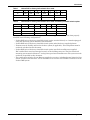
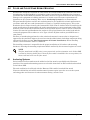
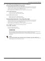
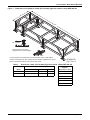
1
Liebert® DSE™
IBC Seismic Supplemental User Manual, 80-165kW, Downflow
TABLE OF CONTENTS
IMPORTANT SAFETY INSTRUCTIONS . . . . . . . . . . . . . . . . . . . . . . . . . . . . . . . . . . . . . . . . . . . . . . . .1
SAVE THESE INSTRUCTIONS . . . . . . . . . . . . . . . . . . . . . . . . . . . . . . . . . . . . . . . . . . . . . . . . .1
1.0
LIEBERT DSE NOMENCLATURE . . . . . . . . . . . . . . . . . . . . . . . . . . . . . . . . . . . . . . . . . . . . .3
2.0
INTRODUCTION . . . . . . . . . . . . . . . . . . . . . . . . . . . . . . . . . . . . . . . . . . . . . . . . . . . . . . . . . .4
2.1
Background . . . . . . . . . . . . . . . . . . . . . . . . . . . . . . . . . . . . . . . . . . . . . . . . . . . . . . . . . . . . . . . . . 4
2.2
Determining Whether a Unit is IBC-Compliant . . . . . . . . . . . . . . . . . . . . . . . . . . . . . . . . . . . 4
2.3
Certification Criteria . . . . . . . . . . . . . . . . . . . . . . . . . . . . . . . . . . . . . . . . . . . . . . . . . . . . . . . . . 4
3.0
SITE REQUIREMENTS OF SEISMIC INSTALLATION . . . . . . . . . . . . . . . . . . . . . . . . . . . . . . . . .6
4.0
FLOOR AND FLOOR STAND SEISMIC MOUNTING . . . . . . . . . . . . . . . . . . . . . . . . . . . . . . . . .7
4.1
Anchoring Systems. . . . . . . . . . . . . . . . . . . . . . . . . . . . . . . . . . . . . . . . . . . . . . . . . . . . . . . . . . . 7
4.1.1
4.1.2
Floor Stand Anchoring Requirements for Seismic Installations . . . . . . . . . . . . . . . . . . . . . . . . 8
Floor Stand Anchoring . . . . . . . . . . . . . . . . . . . . . . . . . . . . . . . . . . . . . . . . . . . . . . . . . . . . . . . . 11
5.0
ELECTRICAL CONSIDERATIONS OF SEISMIC INSTALLATION . . . . . . . . . . . . . . . . . . . . . . . . . 15
6.0
PIPING CONSIDERATIONS OF SEISMIC INSTALLATION . . . . . . . . . . . . . . . . . . . . . . . . . . . . . 17
6.1
Fluid Connections. . . . . . . . . . . . . . . . . . . . . . . . . . . . . . . . . . . . . . . . . . . . . . . . . . . . . . . . . . . 17
6.1.1
6.1.2
Condensate Piping—Field-Installed . . . . . . . . . . . . . . . . . . . . . . . . . . . . . . . . . . . . . . . . . . . . . 17
Humidifier Supply Water—Optional Infrared or Steam Generating Humidifier . . . . . . . . . 17
6.2
Refrigerant Piping . . . . . . . . . . . . . . . . . . . . . . . . . . . . . . . . . . . . . . . . . . . . . . . . . . . . . . . . . . 18
7.0
PLENUM AND DUCTING CONSIDERATION OF SEISMIC INSTALLATION . . . . . . . . . . . . . . . . . . 20
7.1
Plenum Installation . . . . . . . . . . . . . . . . . . . . . . . . . . . . . . . . . . . . . . . . . . . . . . . . . . . . . . . . . 20
7.2
Duct Connections . . . . . . . . . . . . . . . . . . . . . . . . . . . . . . . . . . . . . . . . . . . . . . . . . . . . . . . . . . . 21
8.0
ANCHOR AND LOAD REQUIREMENTS OF SEISMIC INSTALLATION . . . . . . . . . . . . . . . . . . . . 22
9.0
MAINTENANCE . . . . . . . . . . . . . . . . . . . . . . . . . . . . . . . . . . . . . . . . . . . . . . . . . . . . . . . . . 23
9.1
Seismic Bracing . . . . . . . . . . . . . . . . . . . . . . . . . . . . . . . . . . . . . . . . . . . . . . . . . . . . . . . . . . . . 23
9.1.1
Temporary Service Access . . . . . . . . . . . . . . . . . . . . . . . . . . . . . . . . . . . . . . . . . . . . . . . . . . . . . 23
9.2
Inspection of System Connections . . . . . . . . . . . . . . . . . . . . . . . . . . . . . . . . . . . . . . . . . . . . . . 23
9.3
Post-Seismic Inspection . . . . . . . . . . . . . . . . . . . . . . . . . . . . . . . . . . . . . . . . . . . . . . . . . . . . . . 24
i
FIGURES
Figure 1
Figure 2
Figure 3
Figure 4
Figure 5
Figure 6
Figure 7
Figure 8
Figure 9
Figure 10
Figure 11
Dimensions, foot details for 18-48" (457-1219mm) high floor stands, Liebert DSE 080-165 . . . . . 9
Dimensions, foot details for 7" (178mm) high floor stands, Liebert DSE 080-165 . . . . . . . . . . . . 10
Seismic anchoring dimensions, 7" (178mm) floor stands—DA080-DA165 . . . . . . . . . . . . . . . . . . 12
Seismic anchoring dimensions—DA080/085 . . . . . . . . . . . . . . . . . . . . . . . . . . . . . . . . . . . . . . . . . . 13
Seismic anchoring dimensions—DA125/150/165 . . . . . . . . . . . . . . . . . . . . . . . . . . . . . . . . . . . . . . 14
Electrical wiring—seismic considerations . . . . . . . . . . . . . . . . . . . . . . . . . . . . . . . . . . . . . . . . . . . . 16
Horizontal expansion loop . . . . . . . . . . . . . . . . . . . . . . . . . . . . . . . . . . . . . . . . . . . . . . . . . . . . . . . . 18
Vertical expansion loop . . . . . . . . . . . . . . . . . . . . . . . . . . . . . . . . . . . . . . . . . . . . . . . . . . . . . . . . . . 18
Piping—seismic considerations . . . . . . . . . . . . . . . . . . . . . . . . . . . . . . . . . . . . . . . . . . . . . . . . . . . . 19
Plenum seismic mounting data, Liebert DA080/085 . . . . . . . . . . . . . . . . . . . . . . . . . . . . . . . . . . . 20
Seismic duct connection considerations. . . . . . . . . . . . . . . . . . . . . . . . . . . . . . . . . . . . . . . . . . . . . . 21
TABLES
Table 1
Table 2
Table 3
Table 4
Table 5
Table 6
Liebert DSE on factory-built seismic floor stand and factory-installed seismic option . . . . . . . . . 5
Liebert DSE on factory-built seismic floor stand . . . . . . . . . . . . . . . . . . . . . . . . . . . . . . . . . . . . . . . 5
Dimensions, 18-48" (457-1219mm) high floor stands, Liebert DSE 080-165 . . . . . . . . . . . . . . . . . 9
Dimensions for 7" (178mm) high floor stands, LIebert DSE 080-165 . . . . . . . . . . . . . . . . . . . . . . 10
Dimensions in Figure 3 . . . . . . . . . . . . . . . . . . . . . . . . . . . . . . . . . . . . . . . . . . . . . . . . . . . . . . . . . . 12
Downflow Liebert DSE models DA085-165 on floor stand with 18" (457mm) filter plenum . . . . 22
ii
IMPORTANT SAFETY INSTRUCTIONS
This manual contains important safety and installation instructions not included in the Liebert DSE
user manual, SL-18925. The information in this manual is not a substitute for the data in the
Liebert DSE user manual, but provides additional information required for units equipped with the
seismic option. The information in this manual should be read carefully and used to ensure
compliance with the International Building Code. Special inspection per IBC Section 1704 is required
during all installations. Read this document and the Liebert DSE user manual, SL-18925, thoroughly
before attempting to install or operate this unit.
Only properly trained and qualified personnel should move, install or service this equipment.
Adhere to all warnings, cautions and installation, operating and safety instructions on the unit, in the
Liebert DSE user manual, SL-18925, and in this manual. Follow all operating and user instructions.
SAVE THESE INSTRUCTIONS
! WARNING
Arc flash and electric shock hazard. Open all local and remote electric power disconnect
switches and wear protective equipment per NFPA 70E before working within the electric
control enclosure. Failure to comply can cause serious injury or death.
Before proceeding with installation, read all instructions, verify that all the parts are included
and check the nameplate to be sure the voltage matches available utility power.
The Liebert iCOM™ microprocessor does not isolate power from the unit, even in the “Unit
Off” mode. Some internal components require and receive power even during the “Unit Off”
mode of the Liebert iCOM control.
The factory-supplied optional disconnect switch is inside the unit. The line side of this switch
contains live high-voltage. With disconnect Off, check for voltage on the load side.
The only way to ensure that there is NO voltage inside the unit is to install and open a remote
disconnect switch. Refer to unit electrical schematic.
Follow all local codes.
! WARNING
Risk of high-speed moving parts. Can cause injury or death.
Open all local and remote electric power disconnect switches before working in the unit.
! WARNING
Risk of top-heavy unit falling over. Can cause equipment damage, injury or death.
Read all of the following instructions before attempting to move, lift, remove packaging from
or prepare the unit for installation.
! WARNING
Risk of seismic event. Can cause equipment damage, injury or death.
Unit must be welded to the floor stand and anchored to the floor or housekeeping pad. If not
mounted on a floor stand, the unit must be anchored to the floor or housekeeping pad.
! WARNING
Risk of arc flash, infrared exposure, hazardous fumes and toxic gases during welding
operations. Can cause eye, skin and serious respiratory system, choking and breathing
problems.
Welding may produce fumes and gases hazardous to health. Avoid breathing these fumes and
gases. Use adequate ventilation.
Only properly trained and qualified personnel wearing appropriate safety headgear, gloves,
shoes, skin and eye protection should be welding.
1
Liebert® DSE™ IBC Seismic Supplement
! WARNING
Risk of concrete failure and/or loose or unsecured mounting anchors. Can cause unit to fall
over or move during a seismic event resulting in building damage, injury, or death.
Installation in structural, lightweight concrete is not permitted unless otherwise approved by
the structural engineer of record. Structural engineer of record is defined as: The registered
design professional responsible for the design of the designated seismic systems on the building
construction documents.
! CAUTION
Risk of sharp edges, splinters and exposed fasteners. Can cause injury.
Only properly trained and qualified personnel wearing appropriate safety headgear, gloves,
shoes and glasses should attempt to move, lift, remove packaging from or prepare the unit for
installation.
NOTICE
Risk of overhead interference. Can cause unit and/or building damage.
The unit may be too tall to fit through a doorway while on the skid. Measure the unit and
doorway heights and refer to the installation plans to verify clearances prior to moving the
unit.
NOTICE
Risk of damage from forklift. Can cause unit damage.
Keep tines of the forklift level and at a height suitable to fit below the skid and/or unit to
prevent exterior and/or underside damage.
NOTICE
Risk of improper storage. Can cause unit damage.
Keep the Liebert DSE upright, indoors and protected from dampness, freezing temperatures
and contact damage.
NOTICE
Risk of leaking water. Can cause equipment and building damage.
This unit requires a water drain connection. It may also require an external water supply to
operate.
Improper installation, application and service practices can result in water leakage from the
unit. Water leakage can result in severe property damage and loss of critical data center
equipment.
Do not install this unit above equipment or machines that could be damaged by leaking water.
Do not install equipment or machines that could be damaged by leaking water below this unit.
Emerson Network Power® recommends installing leak detection equipment for unit and
supply lines.
NOTICE
Risk of structural damage. Drilling holes all the way through the floor or housekeeping pad
may cause damage to the structure and can result in damage to lower floors.
Drilling holes that penetrate either the floor or the housekeeping pad must be properly filled
and sealed.
Liebert® DSE™ IBC Seismic Supplement
2
Liebert DSE Nomenclature
1.0
LIEBERT DSE NOMENCLATURE
1
D
2
A
3
1
4
2
5
5
6
D
7
A
8
1
9
1
10
11
12
13
1
14
Product Family
DA - Downflow Standard
Nominal kW
80-165
Air Discharge
D = Downflow
R = Front Air Supply
System Type
A - Air Cooled
W - Water/Glycol
P - Air-Cooled with EconoPhase
Airflow (fan type)
1 - EC Plug fans
H - EC Plug fans with THD filter
Voltage
A - 460/3/60
B - 575/3/60
C - 208/3/60
D - 230/3/60
2 - 380/3/60
Factory Configuration Number
000-999
3
Liebert® DSE™ IBC Seismic Supplement
Introduction
2.0
INTRODUCTION
2.1
Background
The International Code Council’s International Building Code (IBC) is the primary code document for
the design and installation of building systems. This has brought about increased scrutiny of
mechanical and electrical equipment that is used in the operation of facilities, particularly those
buildings designated as “essential facilities.” Previously, codes focused only on preventing equipment
from breaking free from anchoring and becoming projectiles, and did not consider its structural
integrity. These new codes, depending on the Use Group and Importance Factor of the building, may
require equipment to function after a seismic event.
IBC-2009 and 2012 has made the manufacturer of mechanical and electrical equipment responsible
for designing, testing and certifying systems. Emerson®, through a recognized, approved agency, has
conducted analytical modeling and dynamic shake-table testing of the Liebert DSE to provide an
option for those systems requiring seismic certification of compliance. The seismic shake-table testing
was conducted in accordance with ICC-ES AC-156. This certification goes beyond the equipment’s
ability to withstand seismic forces. The IBC system approach includes the equipment, equipment
anchoring and the connections to the equipment (power, water supply and return and ducting). In
essential applications the equipment must be capable of performing its primary function after a
seismic event within the limit of certification.
NOTE
An approved agency is defined by IBC section 1702 as: An established and recognized agency
regularly engaged in conducting tests or furnishing inspection services, when such agency has
been approved.
2.2
Determining Whether a Unit is IBC-Compliant
The catalog Liebert DSE unit is IBC-compliant to a maximum Ss of 1.50g (1.50 times the force of
gravity), units must be ordered with the factory-built seismic floor stand. To be IBC-compliant to a
maximum level of Ss of 3.75g, units must be ordered with the factory-installed seismic bracing option.
Liebert DSE units with the seismic bracing option will have:
•
•
•
•
Certification label—near the unit nameplate, behind the front panel
Certificate of compliance—included in the customer envelope with this manual
Factory-installed seismic bracing components
Factory-built seismic floor stand
NOTE
Factory-installed seismic bracing components are painted red and must not be removed.
2.3
Certification Criteria
Liebert DSE units equipped with the seismic option are certified to a maximum Ss of 3.75g (3.75times
the force of gravity), adjusted by the soil site coefficient to Soil Site Class D as the default when
neither the site soil properties nor the final equipment installation location is known. The
certification maximum Sds value of 3.75g includes Soil Class and Seismic Use group corrections. Soil
Classes A, B, C, D, E, Seismic Use groups I, II, III, IV and Seismic Design Categories A, B, C, D, E
and F are all covered under this certification, limited by the Sds value stated above. A seismic
importance factor, Ip, of 1.5 applies to this certification to include essential facility requirements and
life-safety applications for the Liebert DSE system’s functionality after a seismic event. Shake-table
testing conducted in accordance with ICC-ES AC-156 enveloped a required response spectrum (RRS)
defined in the tables below.
Liebert® DSE™ IBC Seismic Supplement
4
Introduction
Table 1
Liebert DSE on factory-built seismic floor stand
Soil Class
Ss =
S1 =
Sds =
Sd1 =
Fa =
Fv =
z/h =
D
1.50
0.64
1.00
0.64
1
1.5
1
AFLEX Horizontal
ARIG Horizontal
AFLEX Vertical
ARIG Vertical
1.60
1.20
0.67
0.27
Table 2
Liebert DSE on factory-built seismic floor stand and factory-installed seismic option
Soil Class
Ss =
S1 =
Sds =
Sd1 =
Fa =
Fv =
z/h =
D
3.75
1.28
multiple
1.28
1
1.5
1.0
Sds =
AFLEX Horizontal
ARIG Horizontal
AFLEX Vertical
ARIG Vertical
2.00
3.20
2.40
N/A
N/A
2.50
N/A
N/A
1.68
0.68
A Liebert DSE, as described above, is approved for seismic application as a system when properly
installed in the following configurations:
• Liebert DSE unit, with factory-installed seismic option, attached directly to a housekeeping pad
using the anchoring system defined in this document.
• Liebert DSE unit, with factory-installed seismic option and with factory-supplied plenum.
• Plenums must be flexibly attached to the duct system (if applicable). Unit and plenum must be
anchored as defined in this document.
• Liebert DSE unit, with factory-installed seismic option, installed on an Emerson-supplied,
IBC-certified floor stand and attached securely to the building structure. The floor stand and
mounting system must be Emerson® catalog items, purchased from Emerson. The system must be
anchored as specified in this document.
• The certification excludes all non-Emerson supplied accessories, including but not limited to floor
stands, isolators and restraints. Use of non-Emerson accessories will void IBC certification of the
Liebert DSE system.
5
Liebert® DSE™ IBC Seismic Supplement
Site Requirements of Seismic Installation
3.0
SITE REQUIREMENTS OF SEISMIC INSTALLATION
All floor and housekeeping pads must be approved by the structural engineer of record to resist the
added seismic loads from components being anchored as specified in 8.0 - Anchor and Load
Requirements of Seismic Installation. When anchoring the Liebert DSE to a floor, rebar
interference must be considered.
The minimum housekeeping pad thickness must be the thickness required by the qualification report
for the selected post-installed anchor or 1.5 times the depth the anchor is embedded, whichever is
greater.
! WARNING
Risk of concrete failure and/or loose or unsecured mounting anchors. Can cause unit to fall
over or move during a seismic event resulting in building damage, injury, or death.
Installation in structural, lightweight concrete is not permitted unless otherwise approved by
the structural engineer of record. Structural engineer of record is defined as: The registered
design professional responsible for the design of the designated seismic systems on the building
construction documents.
Contact your Emerson® representative if a detailed Seismic Installation Calculation Package is
required. The information required to perform the calculations should include (but not be limited to):
Floor Data
• Concrete compressive strength and aggregate content
• Slab or lightweight concrete over metal deck
• Thickness
• Type of reinforcement (rebar, wire mesh or none)
Housekeeping Pad
• Concrete compressive strength and aggregate content
• Length, width and thickness
• Type of reinforcement (rebar, wire mesh or none)
• Doweled to floor or integrated
Liebert® DSE™ IBC Seismic Supplement
6
Floor and Floor Stand Seismic Mounting
4.0
FLOOR AND FLOOR STAND SEISMIC MOUNTING
Whether floor-mounted or installed on a floor stand, the Liebert DSE must be anchored to the floor or
housekeeping pad. Field welding is required for seismic installations. In addition to the clearances
specified in the Liebert DSE user manual, SL-18925, clearance is required behind the unit to prevent
damage to the equipment or building structure in a seismic event. Clearance requirements are
dependent on the system mounting. Refer to 4.1 - Anchoring Systems for recommendations.
The post-installed anchors used for unit anchoring must be pre-qualified for seismic applications in
accordance with ACI 335.2 and documented in a report by a reputable testing agency, such as the
Evaluation Service Report issued by the International Code Council. Anchors must be installed to the
torque specifications recommended by the anchor manufacturers to ensure maximum loading. Wide
washers, sized to match the nominal diameter of the specified anchors, must be used at each anchor
location. For tension load distribution the washer is to be placed between the anchor head and the
connected equipment. The washers are to be Type A, Series W plain washers per ANSI B18.22.1 1965, R1975.
The floor or housekeeping pad must be rebar-reinforced structural concrete that is designed and
approved by the structural engineer of record to resist the added seismic loads from components being
anchored to the floor (see 3.0 - Site Requirements of Seismic Installation). When installing
anchors, rebar interference must be considered.
The installing contractor is responsible for the proper installation of all anchors and mounting
hardware, observing the mounting requirement details outlined by the structural engineer of record.
NOTE
The floor stand used with EC units is not symmetrical, and its orientation to the Liebert DSE
is critical to lowering the EC fans. Unless the floor stand is installed in the correct position, the
blowers will not lower into the floor stand.
4.1
Anchoring Systems
Units installed on floor stands must be welded to the floor stand as specified herein. Emerson®
provides a floor stand and mounting systems as selectable items that are IBC-certified and matched
to the Liebert DSE.
The unit certification is valid only with the Emerson, IBC-certified, matched floor stand.
Clearances behind the unit of floor stand-mounted systems require space for access to the system
anchoring points and clearance for unit movement during a seismic event.
7
Liebert® DSE™ IBC Seismic Supplement
Floor and Floor Stand Seismic Mounting
4.1.1
Floor Stand Anchoring Requirements for Seismic Installations
Anchoring Requirements Without a Floor Stand
•
•
•
•
Anchor selection must meet or exceed IBC 2009 and 2012 compliance requirements.
All anchors listed and any housekeeping pad must be installed to meet compliance.
Anchors must be installed per ICC ESR instructions.
Special inspection per IBC Section 1704 is required on all installations.
Liebert DSE (DA080, 085)
• Twelve (12) concrete expansion anchors
• Twelve (12) Type A, Series W plain washers
Liebert DSE (DA125, 150,165)
• Sixteen (16) concrete expansion anchors
• Sixteen (16) Type A, Series W plain washers
Anchoring Requirements with a 7-inch (178mm) Floor Stand
•
•
•
•
Anchor selection must meet or exceed IBC 2009 and 2012 compliance requirements.
All anchors listed and any housekeeping pad must be installed to meet compliance.
Anchors must be installed per ICC ESR instructions.
Special inspection per IBC Section 1704 is required on all installations.
Refer to Figure 5 for dimensions and anchoring locations.
Liebert DSE—All Models
• 24 concrete expansion anchors
• 24 Type A, Series W plain washers
NOTICE
Risk of structural damage. Drilling holes all the way through the floor or housekeeping pad
may cause damage to the structure and can result in damage to lower floors.
Drilling holes that penetrate either the floor or the housekeeping pad must be properly filled
and sealed.
NOTE
The seismic floor stand is not symmetrical, and its orientation to the Liebert DSE unit is
critical. Unless the floor stand is installed in the correct position, features such as turning vane
and EC plug fans may not function properly.
Liebert® DSE™ IBC Seismic Supplement
8
Floor and Floor Stand Seismic Mounting
Figure 1
Dimensions, foot details for 18-48" (457-1219mm) high floor stands, Liebert DSE 080-165
B
A
4.6" (117mm)
Foot Detail
* Foot provides ±1/4" (6mm)
adjustment from nominal height.
Jack
The floor stand is not symmetrical, and its orientation to the Liebert DSE is
critical to lowering the EC fans. Unless the floor stand is installed in the correct
position, the blowers will not lower into the floor stand.
Table 3
DPN002538
Pg. 5, Rev. 2
Dimensions, 18-48" (457-1219mm) high floor stands, Liebert DSE 080-165
Dimensions, in. (mm)
Overall Unit Length
A
B
Height H*
(Nominal), In. (mm)
DA080/085
100(2540)
99 (2515)
33 (838)
18 (457)
DA125/150/165
144 (3658)
142 (3607)
45 (1143)
24 (610)
Model
30 (762)
Source: DPN002538, Rev. 2
36 (914)
42 (1067)
48 (1219)
9
Liebert® DSE™ IBC Seismic Supplement
Floor and Floor Stand Seismic Mounting
Figure 2
Dimensions, foot details for 7" (178mm) high floor stands, Liebert DSE 080-165
B
A
7"
(178mm)
DPN002538
Pg. 6, Rev. 2
7" (178mm) Foot Detail
No adjustment on 7" (178mm) floor stands.
Table 4
Dimensions for 7" (178mm) high floor stands, LIebert DSE 080-165
Dimensions, in. (mm)
Model
Overall Unit Length
A
B
DA080/085
100 (2540)
99 (2515)
33 (838)
DA125/150/165
144 (3658)
142 (3607)
45 (1143)
Source: DPN002538, Rev. 2
Liebert® DSE™ IBC Seismic Supplement
10
Floor and Floor Stand Seismic Mounting
4.1.2
Floor Stand Anchoring
See Figure 3 for weld and anchoring details of DS080 - DA165 7" (178mm) floor stands; Figure 4 for
weld and anchoring details of DS080/085 floor stands; and Figure 5 for weld and anchoring details of
DS125-165 floor stands.
1. Check the proposed finished floor height.
2. Turn the floor stand over and screw the feet on the bottom until the measurement from the
bottom of the foot to the top surface of the upper tube equals the finished floor height.
3. Turn the floor stand right side up.
4. Place the floor stand in the final location in the correct orientation.
NOTE
The floor stand used with EC units is not symmetrical, and its orientation to the Liebert DSE
is critical to lowering the EC fans. Unless the floor stand is installed in the correct position, the
blowers will not lower into the floor stand.
5. Level the stand by turning the foot/isolator up or down as necessary. Make sure all feet/isolators
are firmly resting on the floor.
6. Tighten foot/isolator jam nuts to prevent movement.
7. Mark foot/isolator hole locations on the floor or housekeeping pad. Remove floor stand and set
floor stand aside.
8. Drill holes and install anchors according to the manufacturer’s recommendations.
9. Set the floor stand into position over the anchor studs and tighten all hardware to the
manufacturer’s torque specifications.
10. Position the unit on the floor stand and weld the unit base to the floor stand gussets using a
1/8" (3mm) continuous weld. See Figures 3, 4 and 5.
! WARNING
Risk of top-heavy unit falling over. Can cause equipment damage, injury or death.
Read all of the following instructions before attempting to move, lift, remove packaging from
or prepare the unit for installation.
! WARNING
Risk of arc flash, infrared exposure, hazardous fumes and toxic gases during welding
operations. Can cause eye, skin and serious respiratory system, choking and breathing
problems.
Welding may produce fumes and gases hazardous to health. Avoid breathing these fumes and
gases. Use adequate ventilation.
Only properly trained and qualified personnel wearing appropriate safety headgear, gloves,
shoes, skin and eye protection should be welding.
11
Liebert® DSE™ IBC Seismic Supplement
Floor and Floor Stand Seismic Mounting
Figure 3
Seismic anchoring dimensions, 7" (178mm) floor stands—DA080-DA165
2"
(51mm)
Anchor Detail
Typical 8 Places
Anchor- 3 Places
ANSI B18.22.1-1965(R2003)
Type A, Series W Plain
Washer Required at
Each Anchor Location
*Minimum
Pad
Thickness
*Minimum
Embedment
B
B
2"
(51mm)
Section B-B
*Minimum Hole
Depth
* Specified by Engineer of Record
Floor Anchoring Dimensions
A
C
B
D
Field Welding of Unit to Floor Stand
Unit Must Be Welded to Floor Stand
to Maintain Certification
G
G
Typ.
F
1/8" (3mm)
F
F
F
F
F
F
Anchor bolt sized per Hilti Kwik Bolt TZ carbon and stainless in concrete, ICC ESR-1917.
Alternates are subject to review by Emerson or engineer of record.
Table 5
DPN002538
Pg. 2, Rev. 2
Dimensions in Figure 3
Model #
A
in. (mm)
B
in. (mm)
C
in. (mm)
D
in. (mm)
DA080;DA085
32.5 (826)
65 (1651)
97.5 (2477)
31.5 (800)
DA125; DA150; DA165
45.5 (1156)
93 (2362)
140.5 (3569)
43.5 (1105)
Source: DPN002538, Rev. 2
Liebert® DSE™ IBC Seismic Supplement
12
Anchor
Size
F
in. (mm)
G
in. (mm)
1/2"
2 (51)
4 (102)
Floor and Floor Stand Seismic Mounting
Figure 4
Seismic anchoring dimensions—DA080/085
Anchor Detail
Typical 8 Places
ANSI B18.22.1-1965(R2003)
Type A, Series W Plain
Washer Required at
Each Anchor Location
*Minimum
Embedment *Minimum Hole
Depth
*Minimum
Pad
Thickness
* Specified by Engineer of Record
Floor Anchoring Dimensions
97-1/2" (2477mm)
48.8"
(1238mm)
31-1/2"
(800mm)
3.3" (83mm)
6-1/2" (165mm)
Field Welding of Unit to Floor Stand
Unit Must Be Welded to Floor Stand
to Maintain Certification
4"
(102mm)
Typ.
2"
(51mm)
Anchor Size: 1/2" (12.7mm)
1/8" (3mm)
2"
(51mm)
2"
(51mm)
4"
(102mm)
2" (51mm)
2"
(51mm)
2"
(51mm)
Anchor bolt sized per Hilti Kwik Bolt TZ carbon and stainless in concrete, ICC ESR-1917.
Alternates are subject to review by Emerson or engineer of record.
13
DPN002538
Pg. 3, Rev. 2
Liebert® DSE™ IBC Seismic Supplement
Floor and Floor Stand Seismic Mounting
Figure 5
Seismic anchoring dimensions—DA125/150/165
Anchor Detail
Typical 8 Places
ANSI B18.22.1-1965(R2003)
Type A, Series W Plain
Washer Required at
Each Anchor Location
*Minimum
Embedment *Minimum Hole
Depth
*Minimum
Pad
Thickness
* Specified By Engineer Of Record
Floor Anchoring Dimensions
140-1/2" (3569mm)
81.3" (2064mm)
22" (559mm)
43-1/2"
(1105mm)
3.3" (83mm)
6-1/2" (165mm)
Anchor bolt sized per Hilti Kwik Bolt TZ
carbon and stainless in concrete, ICC ESR-1917.
Field Welding of Unit to Floor Stand
Alternates are subject to review by
Unit Must Be Welded to Floor Stand to Maintain Certification
Emerson or engineer of record.
4" (102mm)
4" (102mm)
Anchor Size: 1/2" (12.7mm)
2"
(51mm)
2" (51mm)
2" (51mm)
Liebert® DSE™ IBC Seismic Supplement
2"
(51mm)
14
1/8"
(3mm)
2" (51mm)
TYP.
2"
(51mm)
DPN002538
Pg. 4, Rev. 2
Electrical Considerations of Seismic Installation
5.0
ELECTRICAL CONSIDERATIONS OF SEISMIC INSTALLATION
Input power and control wiring connections to the Liebert DSE must be flexible and able to withstand
movement in three dimensions. Relative motion caused by a seismic event must be absorbed to
prevent damage to the unit, building structure and wiring. It is recommended that all connections to
the unit be made as low as possible. The flexible connection should include at least one bend between
the unit connection location and the first clamping point at the foundation or structure. It must be of
sufficient length to makeup for the maximum displacement indicated in Figure 6.
! WARNING
Risk of electric shock. Can cause injury or death.
Open all local and remote electric power disconnect switches before working within unit
electrical enclosures.
Before proceeding with installation, read all instructions, verify that all the parts are included
and check the nameplate to be sure the voltage matches available utility power.
The Liebert iCOM™ microprocessor does not isolate power from the unit, even in the “Unit
Off” mode. Some internal components require and receive power even during the “Unit Off”
mode of the Liebert iCOM control.
The factory-supplied optional disconnect switch is inside the unit. The line side of this switch
contains live high-voltage. With disconnect Off, check for voltage on load side.
The only way to ensure that there is NO voltage inside the unit is to install and open a remote
disconnect switch. Refer to unit electrical schematic.
Follow all local codes.
! WARNING
Risk of high-speed moving parts. Can cause injury or death.
Open all local and remote electric power disconnect switches before working in the unit.
! WARNING
Risk of improper wiring, piping, moving, lifting and handling. Can cause equipment damage,
injury or death.
Installation and service should be done only by personnel who have been properly trained and
qualified in the installation of air conditioning equipment.
! WARNING
Risk of overheated electrical connection terminals. Can cause wiring and component damage,
smoke and fire resulting in building damage, serious injury or death.
Use copper wiring only. Make sure that all connections are tight.
15
Liebert® DSE™ IBC Seismic Supplement
Electrical Considerations of Seismic Installation
Figure 6
Electrical wiring—seismic considerations
Factory-installed Unit
Disconnect Switch (optional)
Field-supplied disconnect
switch when factoryinstalled unit disconnect
switch is not provided
Monitoring
Panel
Three-phase electrical and low-voltage
connections not by Emerson
Seismic Compensation
Flexible conduit and conductors must be provided
to allow the unit to move in three dimensions
during a seismic event. The flexible conduit must
have at least one bend between the rigid connection
at the unit cabinet and the connection to the rigid
conduit or foundation.
Liebert® DSE™ IBC Seismic Supplement
16
DPN002538
Pg. 8, Rev. 2
Piping Considerations of Seismic Installation
6.0
PIPING CONSIDERATIONS OF SEISMIC INSTALLATION
All fluid connections to the unit must be flexible and able to withstand movement in three
dimensions. Relative motion caused by a seismic event must be absorbed to prevent damage to the
unit, building structure and piping. It is recommended that all connections to the unit are made as
low as possible.
6.1
Fluid Connections
NOTICE
Risk of water leaks. Can cause unit and/or building damage. This unit requires a water drain
connection and an external water supply to operate.
Improper installation, application and service practices can result in water leakage from the unit.
Do not install this unit above equipment or machines that could be damaged by leaking water.
Do not install equipment or machines that could be damaged by leaking water below this unit.
Emerson® recommends installing leak detection equipment for unit and supply lines.
6.1.1
Condensate Piping—Field-Installed
! CAUTION
Risk of boiling water. Can cause personal injury.
The unit requires a drain line that may contain boiling water. Only properly trained and
qualified personnel wearing appropriate safety equipment should service the drain line or
work on parts near or connected to the drain line.
Whether supplied with 3/4" NPT gravity drain connection or 1/2" copper sweat connection from a
factory-installed condensate pump, the drain line of the unit will require a flexible element to permit
movement. When selecting a suitable flexible element consider the following:
•
•
•
•
•
6.1.2
The drain line may contain boiling water.
Drain is trapped internally. Do not trap external to the equipment.
Gravity drain line must be sized for 2 gpm (7.61 l/m) flow.
Condensate pump discharge sized based on available head.
Drain line must comply with all applicable codes.
Humidifier Supply Water—Optional Infrared or Steam Generating Humidifier
When selecting a suitable flexible element, permitting movement in three dimensions of sufficient
length to make up for the maximum displacement, consider the following:
• The humidifier supply connection is 1/4" copper line with a maximum water pressure of 150 psi
(1034kPa).
• Size the supply line for 1 gpm (3.8 l/m), with a minimum water pressure of 20 psi (138kPa).
17
Liebert® DSE™ IBC Seismic Supplement
Piping Considerations of Seismic Installation
6.2
Refrigerant Piping
The refrigerant connections of the Liebert DSE, as with all connections, require a flexible element
permitting movement in three dimensions to avoid damage to the unit, structure or piping system.
For these connections, Emerson® recommends flexible expansion loops. Loops typically consist of two
flexible sections of convoluted stainless or bronze metallic hose with braided cover, two elbows and
180° return section with or without support bracket. These loops minimize the seismic loads to the
piping system anchor points. Depending on the manufacturer, the connections to the loop are
available in female copper sweat, NPT thread, flange or grooved.
Figure 7
Horizontal expansion loop
Figure 8
Vertical expansion loop
Manual shutoff valves should be installed at the supply and return lines to each unit. This provides
for routine service and emergency isolation of the unit. To prevent water damage, install a water
detection system, such as a Liebert Liqui-tect® or floor drains with wet traps.
Liebert® DSE™ IBC Seismic Supplement
18
Piping Considerations of Seismic Installation
Figure 9
Piping—seismic considerations
Anchor to
Foundation
Upflow with Floor Stand: Anchor to Floor Stand
Upflow Rigid Mount: Anchor to Unit
Downflow: Anchor to Floor Stand
Liebert
DSE
To Unit
Seismic
Compensation
Device
Secure pipes
to floor stand
Prefabricated seismic
compensation piping
Anchor
Piping
Flexible Loop Example
Floor Stand Mount
Flexible Loops
All units must be attached to the piping system using flexible loops designed for seismic movement. Flexible loops
must be capable of movement in each plane and must completely isolate the equipment from the
piping. The loops must be suitable for the system’s operating pressure and temperature; refer to Emerson
installation instructions. This includes 1/4" copper humidifier supply, condensate drainage and chilled
water supply and return. Follow manufacturer’s installation instructions for proper seismic application of flexible loops.
DPN002538
Pg. 9, Rev. 2
19
Liebert® DSE™ IBC Seismic Supplement
Plenum and Ducting Consideration of Seismic Installation
7.0
PLENUM AND DUCTING CONSIDERATION OF SEISMIC INSTALLATION
7.1
Plenum Installation
Seismic-certified installation of Liebert plenums requires the plenum to be securely attached to the
top of the unit. Refer to the plenum instructions, 197652P1, included with the plenum, for details.
! WARNING
Risk of improper plenum mounting. Can cause equipment damage, injury or death in a
seismic event.
! WARNING
Risk of high-speed moving parts. Can cause injury or death.
Open all local and remote electric power disconnect switches before working in the unit.
! WARNING
Risk of top-heavy unit falling over. Can cause equipment damage, injury or death.
Read all of the following instructions before attempting to move, lift, remove packaging from
or prepare the unit for installation.
NOTE
All clips and fasteners are required to maintain IBC certification of conformity.
Figure 10 Plenum seismic mounting data, Liebert DA080/085
Top Duct Opening Shown
See Specification Sheet
for Specific Application
Plenum Hold-Down Clip Detail
(Front Panel Removed For Clarity)
1/4" Self-Drilling
Screws Through Clip
Into Unit Top and
Plenum Panel Flange
5"
(126mm)
Screws Required: 18
Hold-Down Clips Required: 6
All clips and fasteners are required
to maintain IBC certification of conformity.
2.5"
(63mm)
Plenum Hold-Down Clip Dimensions
2.6"
(66mm)
3.8"
(97mm)
4.4"
(112mm)
1.5"
(39mm)
Liebert® DSE™ IBC Seismic Supplement
20
DPN002538
Pg. 7, Rev. 2
Plenum and Ducting Consideration of Seismic Installation
7.2
Duct Connections
Duct connections made to the unit or unit-mounted plenum must be connected with a flexible
transition that will not transfer damaging loads to the unit or plenum.
NOTE
Special inspection per IBC section 1704 may be required on ductwork installation.
Figure 11 Seismic duct connection considerations
Seismic
Compensation
Downflow Ducting Example for Seismic Applications
All ducted units must be attached to the ducting system using flexible duct designed for seismic movement.
Flexible loops must be capable of movement in each plane and must completely isolate the equipment
from the duct work. Refer to Emerson installation instructions for ducting requirements. Follow
manufacturer’s installation instructions for proper seismic application of flexible ducts.
DPN002538
Pg. 10, Rev. 2
21
Liebert® DSE™ IBC Seismic Supplement
Anchor and Load Requirements of Seismic Installation
8.0
ANCHOR AND LOAD REQUIREMENTS OF SEISMIC INSTALLATION
All floor and housekeeping pads must be approved by the structural engineer of record to resist the
added seismic loads from components being anchored as defined in this section. Data is presented by
system configuration. The maximum system loads are given for each loading location or floor stand
foot. The maximum load at the anchor is provided for proper sizing of the anchors (not provided by
Emerson®).
NOTE
The floor stand used with EC units is not symmetrical, and its orientation to the Liebert DSE
is critical to lowering the EC fans. Unless the floor stand is installed in the correct position, the
blowers will not lower into the floor stand.
NOTE
Load interactions must be considered when selecting anchors.
Table 6
Downflow Liebert DSE models DA085-165 on floor stand with 18" (457mm) filter plenum
Floor Stand
Height,
Model #
in. (mm)
DA080D
DA085D
DA125D
DA150D
DA165D
*
Maximum
Load per Anchor
Operating
Mass *
lb (kg)
Restraint
Locations
48 (1219)
2318 (1051)
6
24 (610)
2222 (1008)
6
7 (178)
2110 (957)
48 (1219)
4248 (1927)
Maximum
Load per Location
Tension
lb. (kg)
Shear
lb. (kg)
Anchors
per
Location
1683.1 (763.4) 302.6 (137.3
3283.4 (1489.3
554.0 (251.3
2
1197.1 (543.0) 290.1 (131.6
2335.0 (1059.1
531.0 (240.9
2
8
507.7 (230.3)
128.5 (58.3
1325.9 (601.4
383.8 (174.1
3
8
1593.9 (723.0) 417.7 (189.5
3156.7 (1431.9
885.1 (401.5
2
Tension
lb. (kg)
Shear
lb. (kg)
24 (610)
4194 (1902)
8
1133.4 (514.1) 412.4 (187.0 2245.17 (1018.3 873.8 (396.4
2
7 (178)
3962 (1797)
8
564.6 (256.1)
3
229.8 (104.2
Operating mass includes the operating refrigerant and water volume, floor stand and plenum
Liebert® DSE™ IBC Seismic Supplement
22
1527.5 (692.9
695.0 (315.2
Maintenance
9.0
MAINTENANCE
! WARNING
Risk of electric shock. Can cause injury or death.
Open all local and remote electric power disconnect switches before working within.
Before proceeding with installation, read all instructions, verify that all the parts are included
and check the nameplate to be sure the voltage matches available utility power.
The Liebert iCOM® microprocessor does not isolate power from the unit, even in the “Unit Off”
mode. Some internal components require and receive power even during the “Unit Off” mode
of the Liebert iCOM control.
The factory-supplied optional disconnect switch is inside the unit. The line side of this switch
contains live high-voltage. With disconnect Off, check for voltage on the load side.
The only way to ensure that there is NO voltage inside the unit is to install and open a remote
disconnect switch. Refer to unit electrical schematic.
Follow all local codes.
! WARNING
Risk of high-speed moving parts. Can cause injury or death.
Open all local and remote electric power disconnect switches before working in the unit.
9.1
Seismic Bracing
Liebert DSE units supplied with the seismic option can be easily identified once the panels are
removed. All seismic bracing is painted red and is factory-installed. Seismic bracing should not be
removed except when absolutely necessary. If any bracing is removed for service access, reinstall it
immediately after servicing unit.
9.1.1
Temporary Service Access
! WARNING
Risk of unit collapse. Can cause injury or death.
Braces are required for seismic certification. If removed for service access, reinstall brace
after servicing unit.
Seismic bracing is fastened to the unit frame with 1/4" self-drilling screws or bolts requiring a
3/8" (10mm) wrench for removal. Any bracing removed for service must be reinstalled, and the 1/4"
fasteners must be tightened to 10 ft-lb. (13.5Nm). If a screw is stripped out, install a replacement at a
new location within 1/2" (12mm) of the original location.
9.2
Inspection of System Connections
Check all connections to the system during routine maintenance and take appropriate action to
correct any issues. System maintenance schedules must be established and performed.
23
Liebert® DSE™ IBC Seismic Supplement
Maintenance
9.3
Post-Seismic Inspection
Many areas of the country that are subject to seismic activity are working to draft local and national
guidelines and procedures for evaluating earthquake-damaged buildings and equipment. In 1989,
with funding from the California Office of Emergency Services, California Office of Statewide Health
Planning and Development and the Federal Emergency Management Agency, the Applied Technology
Council (ATC) published the ATC-20 Procedures for Post Earthquake Safety Evaluation of Buildings.
Inspections outlined in the document, may be required by areas that have adopted ATC-20 and must
be performed by a qualified individual.
The Liebert DSE seismic certification of conformity is an assurance that the system will withstand a
seismic event occurring within the defined limits of 2.3 - Certification Criteria and continue to
perform the primary function of cooling. After any significant seismic event greater than magnitude
6.5, Emerson® requires an inspection of the system structure and connections by a registered
professional engineer with five years of experience in seismic anchorage. This inspection will apply to
equipment within a 100 mile (160km) radius of the seismic event. If evidence of structural cracks,
yielding or loosening of structural members is found, the system must be replaced or restored to the
original design configuration.
Liebert® DSE™ IBC Seismic Supplement
24
Maintenance
NOTES
25
Liebert® DSE™ IBC Seismic Supplement
Maintenance
Liebert® DSE™ IBC Seismic Supplement
26
Technical Support / Service
Web Site
www.liebert.com
Monitoring
[email protected]
800-222-5877
Outside North America: +00800 1155 4499
Single-Phase UPS & Server Cabinets
[email protected]
800-222-5877
Outside North America: +00800 1155 4499
Three-Phase UPS & Power Systems
800-543-2378
Outside North America: 614-841-6598
Environmental Systems
800-543-2778
Outside the United States: 614-888-0246
Locations
While every precaution has been taken to ensure the accuracy
and completeness of this literature, Liebert Corporation assumes no
responsibility and disclaims all liability for damages resulting from use of
this information or for any errors or omissions.
© 2014 Liebert Corporation
All rights reserved throughout the world. Specifications subject to change
without notice.
® Liebert is a registered trademark of Liebert Corporation.
All names referred to are trademarks
or registered trademarks of their respective owners.
United States
1050 Dearborn Drive
P.O. Box 29186
Columbus, OH 43229
Europe
Via Leonardo Da Vinci 8
Zona Industriale Tognana
35028 Piove Di Sacco (PD) Italy
+39 049 9719 111
Fax: +39 049 5841 257
Asia
29/F, The Orient Square Building
F. Ortigas Jr. Road, Ortigas Center
Pasig City 1605
Philippines
+63 2 687 6615
Fax: +63 2 730 9572
SL-18928 _REV1_03-14
Emerson Network Power
Liebert
www.emerson.com
www.EmersonNetworkPower.com