1
User ’s Manual
LG Programmable Logic Controller
GLOFA
Fnet (FieldBus)
Mnet (Mini-Map)
L G Industrial Systems
Contents
Contents
Chapter 1 Introduction ..........................................................................1-1
Chapter 2 Terms and concepts of communication
2.1
2.2
Description of terms ......................................................................................2-1
Concept of Fnet communication ..................................................................2-4
2.2.1
How to generate and move LAS ..................................................................................................... 2-4
2.2.2
How to assign token ............................................................................................................................ 2-4
2.3
Concept of Mnet communication ................................................................. 2-5
2.3.1
How to generate and move token ................................................................................................... 2-5
2.3.2
Token Passing ....................................................................................................................................... 2-5
Chapter 3 General specifications
3.1
3.2
General specifications of communication module(Fnet, Mnet) ...............3-1
Structure and configuration............................................................................ 3-2
3.2.1
Fnet master module str ucture : G3L-FUEA, G3L-FUOA, G4L -FUEA, G6L-FUEA ....... 3-2
3.2.2
Fnet slave module structure : G3L-RBEA, G3L -RBOA, G4L-RBEA .................................. 3-4
3.2.3
Fnet Computer interface module structure : G0L-FUEA........................................................... 3-6
3.2.4
3.2.5
Fnet LED signal name and indication content ............................................................................ 3-7
Fnet station number setting .............................................................................................................. 3-7
3.2.6
Fnet mode setting ................................................................................................................................. 3-8
3.2.7
Mnet module structure : G3L-MUEA
3.2.8
Mnet Computer interface module structure : G0L-MUEA
.........................................................................................3-10
..................................................3-11
Chapter 4 Transmission specifications
4.1
Transmission specifications of Fnet ...........................................................4-1
4.1.1
Transmission specifications of Fnet Master module .................................................................. 4-1
4.1.2
Transmission specifications of Fnet Slave module ................................................................... 4-2
4.1.3
Transmission specifications of Fnet Option module ................................................................. 4-2
4.2
4.3
Transmission specifications of Mnet ...........................................................4-4
Cable specifications .......................................................................................4-5
4.3.1
Twisted pair cable for Fnet ................................................................................................................ 4-5
4.3.2
4.3.3
Optical cable for Fnet .......................................................................................................................... 4-6
Coaxial cable for Mnet ........................................................................................................................ 4-7
Contents
4.4
How to connect communication cable ........................................................ 4-8
4.4.1
Electric(twiste d pair) cable connection ............................................................................................4-8
4.4.2
Electric(twiste d pair) cable connector connection .....................................................................4-8
4.4.3
Optical cable connection .................................................................................................................... 4-9
4.5
Terminal resistance ....................................................................................... 4-9
4.5.1
Electric network terminal resistance of Fnet ............................................................................... 4-9
4.5.2
Terminal resistance of Mnet ............................................................................................................4-10
Chapter 5 System configuration
5.1
5.2
GLOFA PLC network system ........................................................................ 5-1
Fnet network system ..................................................................................... 5-2
5.2.1
Configuration o f Fnet master system (electric network) .......................................................... 5-2
5.2.2
Configuration of Fnet master system (optical network) ...........................................................5-2
5.2.3
5.2.4
5.2.5
Configuration of Fnet master system ( network combined with electric/optical module) 5-3
Configuration of Fnet slave system (electric network) .............................................................5-4
Configuration of Fnet slave system (optical network) ..............................................................5-5
5.2.6
Configuration of Fnet slave system (electric/optical network) ............................................... 5-6
5.2.7
Configuration of Fnet combined system (electric/optical network) ....................................5-7
5.3
Mnet network system .................................................................................... 5-9
5.3.1
System configuration of Mnet ...........................................................................................................5-9
5.3.2
System configuration of Mnet
(including other company’s product - Ex. GOLDSEC-M series).............................................5-9
5.4
Combined system of Fnet and Mnet .......................................................... 5-10
Chapter 6 Communication program
6.1
6.2
Programming method...................................................................................... 6-1
High speed link .................................................................................................. 6-2
6.2.1
6.2.2
Introduction .............................................................................................................................................6-2
Tx/Rx data processing of high speed link .........................................................................................6-3
6.2.3
Operation procedure by high speed link ............................................................................................6-4
6.2.4
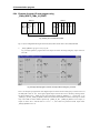
Parameter setting of high speed link ................................................................................................6-5
6.2.5
6.2.6
Operation of high speed link ..............................................................................................................6-11
Relation between high speed link and CPU mode switch .........................................................6-13
6.2.7
Communication status information of high speed link ..............................................................6-14
6.2.8
Speed calculation of high speed link ................................................................................................6-19
6.2.9
Ex. 1 : High speed link among PLCs of Fnet ...............................................................................6-23
6.2.10 Ex. 2 : High speed link of master + remote I/O stations i n Fnet ...........................................6-26
Contents
6.3
Function block service ................................................................................ 6-28
6.3.1
Introduction .............................................................................................................................................6-28
6.3.2
Programming procedure of function block .................................................................................6-28
6.3.3
6.3.4
Types of function block .....................................................................................................................6-29
Input/ou tput of function block .........................................................................................................6-29
6.3.5
How to use function block ..................................................................................................................6-30
6.3.6
Function block library of link .............................................................................................................6-31
CONNECT ..............................................................................................................................................6-33
RDARRAY............................................................................................................................................... 6-36
WRARRAY ..............................................................................................................................................6-38
RDBLOCK ............................................................................................................................................... 6-40
WRBLOCK ..............................................................................................................................................6-42
RDTYPE(BOOL … DT).........................................................................................................................6-44
WRTYPE(BOOL … DT)........................................................................................................................6-47
STATUS ...................................................................................................................................................6-49
6.3.7
6.3.8
6.4
Error received from communication module ............................................................................... 6-55
Access variable registration ..............................................................................................................6-57
GMWIN remote connection service ...........................................................6-62
6.4.1
Introduction ...........................................................................................................................................6-62
6.4.2
6.4.3
GMWIN remote connection ............................................................................................................6-63
Remote module information ...........................................................................................................6-70
6.5
6.5.1
6.5.2
6.6
Function block service for FSM(Fnet Slave Module) ...............................6-72
Function block s of special slave module ......................................................................................6-72
Function block s of reading/writing in slave module ..................................................................6-79
Use of communication module flag .............................................................6-81
6.6.1
Types of flags ......................................................................................................................................6-81
6.6.2
6.6.3
Major flag types used in Fnet ...........................................................................................................6-82
How to use flag in GMWIN................................................................................................................6-83
6.6.4
Example of remote I/O reset program using _FSMx_RESET/_FSMx_IO_RESET .......6-84
6.6.5
Example of application program for restoring instant power off in the
6.6.6
remote module .......................................................................................................................................6-86
Special module access by using _NET x_LIV[n] and _NETx_RST[n] ................................6-87
6.6.7
Setting emergency output data o f remote module....................................................................6-90
Chapter 7 Diagnosis function
7.1
Self diagnosis function of Fnet communication module ..........................7-1
7.1.1
Self diagnosis function during running .......................................................................................... 7-1
7.1.2
Communication diagnosis by test mode ....................................................................................... 7-1
Contents
7.2
Mnet diagnosis function ................................................................................. 7-3
7.2.1
Diagnosis function types of Mnet communication module .....................................................7-3
7.2.2
How to diagnose Mnet communication module .........................................................................7-3
Chapter 8 Installation and testing operation
8.1
Installation and testing operation of Fnet communication module ......... 8-1
8.1.1
8.1.2
Installation of Fnet master module .................................................................................................8-1
Installation of Fnet slave module .....................................................................................................8-2
8.1.3
Installation procedure of Fnet module ...........................................................................................8-3
8.1.4
Cautions on installation of Fnet module ........................................................................................8-4
8.1.5
8.1.6
Preparations during testing operation of Fnet module .............................................................8-6
Testing operation procedure of Fnet module ..............................................................................8-7
8.2
8.2.1
8.2.2
8.2.3
8.3
Installation and testing operation of Fnet option unit ............................... 8-9
Active coupler of Fnet............................................................................................................................8-9
E/O converter(Electric/optical signal con verter) .......................................................................8-10
Repeater(Electric signal restructure) ...........................................................................................8-11
Installation and testing operation of Mnet communication module ...... 8-12
8.3.1
8.3.2
Mounting and installation .................................................................................................................8-12
Cautions on system configuration ...................................................................................................8-15
8.3.3
Preparations before testing operation ............................................................................................8-15
8.3.4
Procedure of testing operation .........................................................................................................8-16
8.4
Repair and check ......................................................................................... 8-18
8.4.1
Daily check ............................................................................................................................................8-18
8.4.2
Regular check ......................................................................................................................................8-19
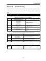
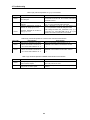
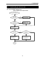
Chapter 9 Troubleshooting
9.1
9.2
9.2.1
Abnormal operations ..................................................................................... 9-1
Troubleshooting by each error code ........................................................... 9-3
Error code E00-01 : Hardware error ............................................................................................... 9-3
Error code E00-03 : Hardware error of option module ............................................................... 9-3
9.2.2
Error code E00-02 : Interface error ................................................................................................9-4
9.2.3
9.2.4
Error code E00-04 : I/O initialization error of FSM(Fieldbus Slave Module) .................... 9-5
Error code E01-01 : Communication failure in Fnet .................................................................9-6
Error code E01-02 : Communication failure in Mnet ................................................................9-6
Error code E01-03 : Communication failure in FOU group .................................................... 9-6
9.2.5
9.2.6
Error code E02-01 : PLC interface error during operation .....................................................9-7
Error code E02-02 : Slave mounting and writing interface error during operation .........9-8
9.2.7
Error code E03-01 : High speed link parameter error ................................................................9-9
Contents
9.2.8
Error code E03-02 : High speed link not run ............................................................................... 9-10
9.2.9
Error code E03-03 : RUN link contact of high speed link not ON .........................................9-11
9.2.10
Error code E03-04 : Trouble contact of high speed link ON ..................................................9-12
9.2.11
Error code E04-01 : Execution error of Fnet communication command .........................9-13
Error code E04-02 : Execution error of Mnet communication command .......................... 9-13
9.2.12
Error code E05-01 : Time out error in GMWIN communication............................................9-14
9.2.13
Error code E05-02 : Internal error in the Fnet/Mnet GMWIN communication ............... 9-15
Appendix
A1.
LED specifications .........................................................................................A-1
A1.1
A1.2
LED specification of Fnet master module .................................................................................... A-1
LED specification o f slave module ................................................................................................. A-4
A1.3
LED specification o f stand-alone type remote module(G0L-SMQA/SMIA/SMHA) ........ A-7
A1.4
LED specification of repeater module(G0L -FREA) ................................................................... A-7
A1.5
A1.6
LED specification o f electric and optical signal switching module(G0L-FOEA) .............. A-7
LED specification of active coupler module(Optical signal distributor) .............................. A-7
A1.7
LED specifications of Mnet communication module ................................................................. A-8
A2.
A3.
Communication module setting in the Fnet/Mnet PC ................................A-10
STATUS code value and description for function block ...........................A-11
A3.1
Errors received from com munication module ...........................................................................A-11
A3.2
STATUS values indicated in CPU ................................................................................................A-12
A4.
Outward dimension ......................................................................................A-13
A4.1
For mounting GM1/2/3 ......................................................................................................................A-13
A4.2
For mounting GM4 .............................................................................................................................A-15
A4.3
For mounting on GM6 .......................................................................................................................A-16
A4.4
A4.5
For mounting on PC(Computer) ....................................................................................................A-17
Fnet option module ............................................................................................................................A-18
4-1
1. Introduction
Chapter 1
Introduction
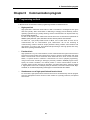
This User's Manual describes for the entire network of GLOFA PLC system technically and in detail. Network of
GLOFA PLC system consists of GLOFA Mnet and GLOFA Fnet according to the type of the unit and the
application, and the characteristics are as follows :
GLOFA Mnet
This is based on international standard network of factory automation, Mini-MAP(FAIS2.0) and situated at medium
level of CIM network structure connecting medium/super controller(GM1, GM2, GM3 PLC) and medium/micro PC
each other, and this is open network system for data communication of massive capacity and real time
communication. This network is based on the international standard and can be connected easily with other
company's communication module by simple parameter setting only.
GLOFA Fnet
This is situated at lower level of CIM network structure, and an open network system based on IEC/ISA Fieldbus of
which standardization is in proceeding. Main characteristics of this network are reduction of the price for installation
and maintenance, variety of system configuration, ease of maintenance and repair, and ease of system modification.
This network supports electric network(twisted pair cable) which is cheap and easy to install and optical
network(optical cable) which has great performance at the place that electric environment is very poor, for variety of
system configuration. This also provides the option module that is composed of repeater, optical/electric converter,
and active coupler, in order to combine suit ably these two networks according to the use.
Remark
1. GLOFA Mnet and GLOFA Fnet are abbreviated as Mnet and Fnet for simp licity of description.
2. Program in this User’s Manual has been prepared on the basis of GMWIN2.0.
1-1
1. Introduction
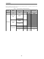
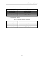
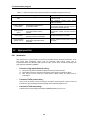
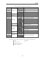
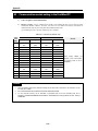
Modules configuring GLOFA Mnet and GLOFA Fnet are classified as Table 1.1 according to the cable used. This
may be referred to when user configures network.
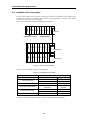
Table 1.1 Type of GLOFA PLC communication module
Network
GLOFA Mnet
Module
Computer
Module
Master module
(FMM)
Type of
connection cable
Coaxial
Name of
communication module
Interface
Twisted pair
(electric)
Interface
Optical
Twisted pair
GLOFA Fnet
Slave module
(electric)
Remote I/O
(FSM)
Optical
Mounting base
G0L-MUEA
Computer
G3L-MUEA
GM1, GM2, GM3
G0L-FUEA
Computer
G3L-FUEA
GM3
G4L-FUEA
GM4
G5L-FUEA
GM5
G6L-FUEA
GM6
G3L-FUOA
GM1, GM2, GM3
G3L-RBEA
GM3
G4L-RBEA
GM4
G0L-SMQA
Single
G0L-SMIA
Single
G0L-SMHA
Single
G3L-RBOA
GM3
Twisted pair
Repeater
G0L-FREA
Single
Optical/Twisted pair
Optical/electr
ic converter
G0L-FOEA
Single
Optical
Active
coupler
Option module
1-2
G0L-FACA
G0L-FAPA
G0L-FABA
Single
2. Terms and Concepts of communication
Chapter 2
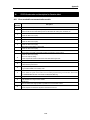
2.1
▣
Terms and concepts of communication
Description of terms
Master module(Fnet Master Module ; FMM)
Fnet communication module mounted at I/O position of main base.
▣
Slave module(Fnet Slave Module; FSM)
Fnet communication module and stand-alone module mounted at CPU position of main base.
▣
Option module(Fnet Option Module)
Fnet communication module used for signal conversion, extension of communication distance, and
regeneration and amplification of signal.
▣
MCM communication module(Mnet Communication Module)
M net communication module mounted at I/O position of main base.
▣
Local station
The station that GMWIN is directly connected in order to download, monitor, and debug programs in the
same network including CPU.
▣
Remote station
The opposite concept to local station, the other station to communicate with local station
▣
Remote I/O station
Input/output area that the remote communication module of PLC system instead of CPU of PLC refreshes
I/O module mounted on remote station by receiving I/O data from master station.
▣
Mnet
This can be compared with the full map, which accommodates all of the concept and functions of the
structure of seven layers suggested by OSI(Open Systems Interconnection). The specification consists of
two lower layers(physical layer, data link layer) for the factory automation which demands reliability, rapid
response, and real time control, one layer for application, and user layer for interface with user.
▣
Fnet
Fieldbus is the lowest network connecting control device and instrumentation device, and the specification
adopts three layers from seven layers of OSI. Three layers consist of the physical layer which consists of
H2(1Mbps, electric), H1(31.23Kbps, electric), optical, and wireless, etc., the data link layer which adopts
scheduled and circulated token bus, the application layer which plays a role of application, and additional
user layer.
2-1
2. Terms and Concepts of communication
▣ TAP
The coaxial line distributor that branches communication line to connect with several stations from one
communication line in GLOFA Mnet.
▣ Token
The right to transmit data of self station through controlling the right of accessing to physical medium.
▣ SAP(Service Access Point)
The factor to determine the characteristic of service used in communication, and to connect upper
application layer with data link layer according to their characteristics. LSAP is divided into SSAP, which
is SAP’s own station and DSAP, which is SAP of other station. (LSAP = SSAP + DSA P, used for Mnet
only)
▣ Mnet station number
The unique station number of G3L-MUEA and G0L-MUEA communication module adopting Mini -MAP
specification. This station number uses MAC address of 6 byte as Mnet station number according to
communication specifications, and this is used as Mnet station number for all services except high speed
link . The station number switch attached on the front of communication module is a high speed link station
number of two byte used in high speed link service only.(High speed link is used in communication with
GLOFA product only)
▣ Fnet station number
The station number of communication module(G3L-FUEA,... etc.) adopting Fnet specification. The station
number used in Fnet is set by the switch attached on the front of communication module, and used as
station number of all services including high speed link service differently from the station number used for
Mnet.
▣ Active coupler
This is a module connecting optical module each other when optical network is configured, and the optical
distributor, which has function of regeneration and amplification of optical communication signal
additionally.
▣ Repeater
This is used to extend the distance of cable for electric communication network, extends the distance of
communication with regeneration and amplification of electric communication signal.
▣ E.O.C(Electric/Optical Converter)
This module converts optical communication signal to electric communication signal, or electric
communication signal to optical communication signal, and has additional functions of regeneration and
amplificat ion of signal.
2-2
2. Terms and Concepts of communication
▣
Manchester Biphase -L
Data modulation method used in Fnet. Data is encoded and transmitted by using Manchester-l code,
Received data encoded by Manchester will be decoded and converted.
▣
CRC(Cyclic Redundancy Check)
This is the one of error detection methods, which is an error detection method used most frequently for
synchronizing transmission, and also called as cyclic code method.
▣
Terminal resistance
This is used to adjust mutual impedance of transmitting part and receiving part on physical layer, and
terminal resistance of Fnet is 110Ω, 1/2W and terminal resistance of Mnet is 75Ω, 1/4W.
▣
High speed link
This is used among GLOFA PLC communication modules only, and used to transmit and receive data at
high speed, and executes communication by setting high speed link parameter of GMWIN.
▣
GMWIN(Programming and debugging tool)
This software enables user to program in order to fit to the system, and to download, run, stop, and debug in
GLOFA PLC CPU module.
▣
FAM(FA Manager)
This software package is situated at upper level in factory automation, and enables user to connect with
networks of several types, and enables user to execute high speed link, reading/writing variable, and
download/upload program by mounting Fnet or Mnet module of computer.
▣
Segment
Local network which connects all stations by using the same token, without using any connecting
device(Gateway, EOC, Repeater).
▣
Network
Entire communication system, configured by one segment or more, that uses the same token.
2-3
2. Terms and Concepts of communication
2.2
Concept of Fnet communication
The method of Fnet communication is token distribution method by LAS(Link Active Scheduler). One of
FMM communication modules can be LAS, but FSM communication modules cannot be LAS.
2.2.1 How to generate and move LAS
Among communication modules, LAS can be generated under the following conditions :
1)
Among the stations connected to network, FMM communication module that the power is turned on
first obtains LAS.
2)
3)
When the power become on at the same time among the stations connected to network, the
communication module with the lowest station number obtains LAS.
If the present LAS station becomes down during normal communication, the communication module
of the lowest station number among the rest of FMM station, obtains LAS.
4)
Only one LAS exists through the entire network.
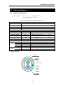
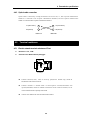
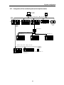
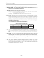
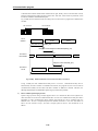
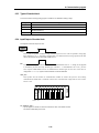
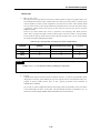
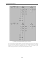
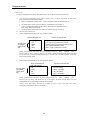
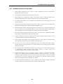
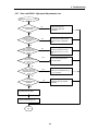
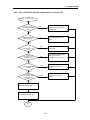
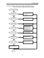
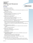
2.2.2 How to assign token(Suppose that the Station FMM_01 is LAS)
FMM_01(LAS)
FMM_02
FMM_03
FMM_04
FMM_05
Token
transmission
of station
FMM_02
Circulated
Token
Passing
Return of token
Token
transmission of
station FSM_03
Return of
token
Token
transmission of
station FSM_04
Return of
token
Return of token
Token
transmission of
station FSM_05
Data
transmission
of LAS’s own
station
Use within
8ms
Token transmission of
FMM_01 (LAS station
also transmits its own
FMM 01)
Return of
token
Data transmission
of self station
Use within 8ms
Data transmission of
self station
Use within 8ms
2-4
*
Data transmission of
self station
Use within 8ms
Data transmission of
self station
Use within 8ms
Token return in each
station is performed
to present LAS
station.
2. Terms and Concepts of communication
2.3
Concept of Mnet communication
Mnet communication method executes communication by using token passing method of IEEE 802.4.. In
this method, a station receives the token transmitted from other station, transmits data of self station, and
hands the token to next station.
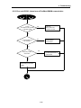
2.3.1 How to generate and move token
1)
Among the stations connected to network, communication module that the power is turned on first
obtains token.
2)
When the power is turned on at the same time among the stations connected to network, the
3)
communication module with the highest station number obtains token.
The station that generated token first, hands the token to the next station found, and stores the station
number.
4)
If the station that the token exists presently becomes down, the next highest station module generates
token newly.
5)
Only one token exists through the entire network.
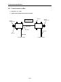
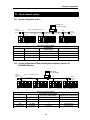
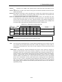
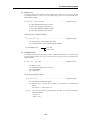
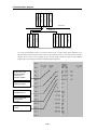
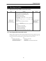
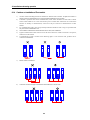
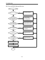
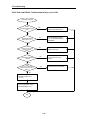
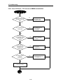
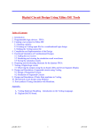
2.3.2 Token Passing
MCM_01
MCM_02
MCM_03
MCM_04
MCM_05
Token passing
(station 02)
Data transmission
of self station
Use within THT
Token passing (station
03)
Data transmission
of self station
Use within THT
Token passing (station
04)
Data transmission
of self station
Use within THT
Token passing (station
05)
Token passing (station
01)
Data transmission of
LAS’s own station
Use within THT
Data transmission
of self station
Use within THT
THT : Token Hold Time(The time that one station can use token, which is
set in network parameter. Default : 2.3 ms).
2-5
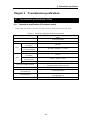
3. General specifications
Chapter 3
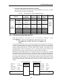
3.1
General specifications
General specifications of communication module(Fnet, Mnet)
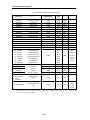
General specifications of GLOFA-GM series are as follows :
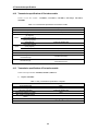
Table 3.1 General specification
No.
Item
1
Operating temp.
0℃~+55℃
Spec.
2
Storage temp.
-25℃~+75℃
3
Operating moist.
5~95% RH, non-condensing
4
Storage moist.
5~95% RH, non-condensing
Related spec.
For discontinuous vibration
Frequency
5
Vibration
Acceleration
Amplitude
10≤f<57Hz
-
0.075mm
57≤f<150Hz
9.8 ㎨{1G}
-
For continuous vibration
Frequency
6
Impact
Number
Acceleration
Amplitude
10≤f<57Hz
-
0.035mm
57≤f<150Hz
4.9 ㎨{0.5G}
-
Each 10 times in
X,Y,Z directions
• Max. impact acceleration:147 ㎨(15G)
• Authorized time : 11ms
• Pulse wave : Sign half-wave pulse(each 3 times in X,Y,Z
directions)
Square wave
Noise
Static electric
discharging
Voltage : 4kV(Contact discharging)
Radiation
electric field
noise
27~500 MHz, 10V/m
Fast
transient/burst
noise
Segment
Voltage
8
Ambient conditions
9
Height
10
Pollution level
11
Cooling type
IEC 1131-2
Test spec. reference
within LG Industrial
Systems
±1,500V
Impulse noise
7
ICE 1131-2
Power
module
2kV
IEC 1131-2,
IEC 801-2
IEC 1131-2,
IEC 801-3
Digital
input/
output
(24V or
more)
Digital input/output
(less than
24V)Analog
input/output
communication
interface
1kV
0.25 kV
IEC 1131-2,
IEC 801-4
No corrosive gas and dust
Up to 2,000m
2 or less
Natural air cooling
Remark
1.
2.
IEC(International Electro-technical Commission) : International non-governmental association, which
establishes international standards in the field of electric and electronics.
Pollution level : This is an indication showing pollution of surrounding environment, which determines
insulation performance of device, and generally the pollution level 2 means the conditions in which only
non-conductive pollution occurs.
But, temporary conduction may occur according to condensing.
3-1
3. General specifications
3.2
Structure and configuration
This describes the structure and configuration for representative type of Fnet and Mnet module.
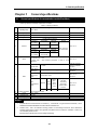
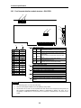
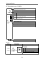
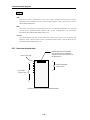
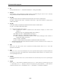
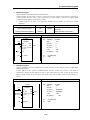
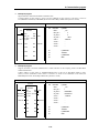
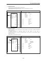
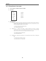
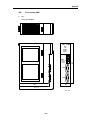
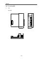
3.2.1 Fnet master module structure : G3L-FUEA, G3L-FUOA, G4L-FUEA, G6L-FUEA
1) G3L-FUEA, G3L-FUOA, G4L-FUEA
Ex. of G3L-FUEA
G3L-FUEA
RUN
LAS
TOKEN
TX/RX
FAULT
Type name indicating section
Indicates type name of communication module
LED indicating section
RUN
Indicates the status of CPU module and interface
LAS
Indicates that communication module is performing LAS function.
TOKEN
Indicates whether communication module has a token or not.
×10
Tx/Rx
Indicates whether communication module is transmitting/ receiving
or not.
×1
FAULT
Flickers when the error that normal operation is not possible
occurred in communication module
MODE
Station number setting switch
Sets station number in the range of 0~63 station(Use decimal).
Mode setting switch
Sets operation mode of communication module
CON1
Communication connector
Connector for electric cable connection to connect communication module.
CON2
Remark
1.
In the figure shown above, connector of G3L-FUOA is made of optical connector.
2.
For mode setting switch, see 3.2.6 Fnet mode setting.
3-2
3. General specifications
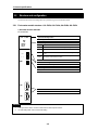
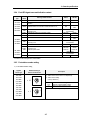
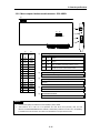
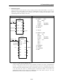
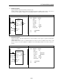
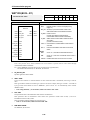
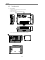
2) G6L-FUEA
RUN
LAS
TOKEN
TX/RX
LED indicating section
FAULT
G6L-FUEA
MODE
RUN
Indicates the status of CPU module and interface
LAS
Indicates that communication module is performing LAS function.
TOKEN
Indicates whether communication module has a token or not.
Tx/Rx
Indicates whether communication module is transmitting/ receiving
or not.
FAULT
Flickers when the error that normal operation is not possible
occurred in communication module
0:ON-LINE
1:TEST1
2:TEST2
Type name indicating section
Indicates type name of communication module
CON1
Mode setting switch
Sets operation mode of communication module
CON2
Communication connector
Connector for electric cable connection to connect communication module.
Remark
1.
The station number setting switch is placed in the case.
3-3
3. General specifications
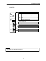
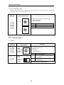
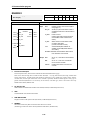
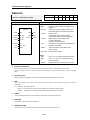
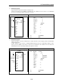
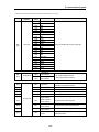
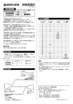
3.2.2 Fnet slave module structure : G3L-RBEA, G3L-RBOA, G4L-RBEA
1) Front part(Ex. G3L-RBEA)
G3L-RBEA
RUN
TOKEN
TX/RX
FAULT
SYS FAULT
×10
×1
MODE
0:ON-LINE
1:TEST1
2:TEST2
Type표시부
name indicating section
형명
Indicates
type형명
name표시
of communication module
통신 모듈의
LED
indicating section
LED
표시부
RUN 통신Indicates
RUN
모듈의 the
상태status
표시 of communication module
TOKEN
모듈의 whether
토큰 소유
communication
여부를 표시 module has a
TOKEN 통신Indicates
or not.
TX/RX 통신token
모듈의
송수신 여부 표시
whether
communication module is
FAULT
에러 발생시
점멸
Tx/Rx 통신Indicates
transmitting/receiving or not.
SYS
시스템 자체의 심각한 오류 발생 또는 I/O 모듈 에러
FAULT
점멸when the communication error occurred.
FAULT 발생시
Flickers
SYS
Flickers when serious error of system itself or I/O module
국번
설정 스위치
FAULT
error occurred
0~63국 사이의 범위를 설정(10진수로 설정)
Station number setting switch
모드
스위치
Sets설정
station
number in the range of 0~63 station(Set in decimal).
통신 모듈의 동작 모드 설정
Mode setting switch
Sets operation mode of communication module
RS232C
Communication
connector (RS-232C)
통신
커넥터 (RS-232C)
Cable
of GMWIN
connection.
GMWIN connector
접속용 케이블
커넥터
CON1
Communication
connector
통신
커넥터
Connector
for연결하기
electric cable
connect커넥터
communication
통신 모듈을
위한connection
전기케이블to 접속용
module.
CON2
Remark
In the figure shown above, connector of G3L- RBOA is made of optical connector, and there is no RS-232C
port in G4L-RBEA.
3-4
3. General specifications
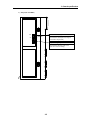
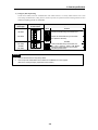
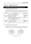
2) Side part(Ex. G3L-RBEA)
Station
국번
설정number
스위치 setting switch
X10
Sets
master
number
remote설정
리모트
통신station
모듈의
모국 of
국번을
communication
module(Set
in the설정)
range of
(10진수로 0~63국
사이의 범위
0~63 station using decimal).
비상데이터 출력
Output of emergency data
통신케이블 단선등에 의한 통신 불능시
Specifies
output
data 지정
type when
출력 데이터
형태를
communication
failure by 참조)
cable cut off.
(3.2.6 Fnet 모드설정항
(See 3.2.6 Fnet mode setting)
X1
3-5
3. General specifications
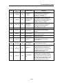
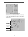
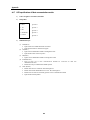
3.2.3 Fnet Computer interface module structure : G0L-FUEA
⑤
④
X1 X10
③
①
Port
②
⑥
1 2
3 4
5 6
Address
⑦
①
②
③
0
1
2
3
4
5
6
7
8
9
A
B
C
D
E
F
Port
포트선택
selection
Address
주소선택
selection
3E0 3E0
FC00
FC00
F800
F800
F400
F400
F000
F000
EC00
EC00
E800
E800
E400
E400
E000
E000
DC00
DC00
D800
D800
D400
D400
D000
D000
CC00
CC00
C800
C800
C400
C400
C000
C000
0
1
2
3
4
5
6
7
8
9
A
B
C
D
E
F
3C03C0
3A0 3A0
380380
360360
340340
320320
300300
2E0 2E0
2C02C0
2A0 2A0
280280
260260
240240
220220
200200
④
⑤
LED indicating section
LED 표시부
No.1 POWER Indicates whether power is being supplied to
1번 POWER 통신 communication
모듈에 전원 공급
module
여부 표시
No.2
RUN
Indicates
the
status
of CPU
module and interface
2번 RUN
CPU 모듈과 인터페이스 상태
표시
Indicates that communication module is performing
No.3
LAS
3번 LAS
통신 LAS
모듈이
LAS 기능 수행중임을 표시.
function.
Indicates
whether
No.4
4번 TOKEN
TOKEN
통신 모듈의 토큰
소유communication
여부를 표시 module has token
or not.
5번 TX/RX 통신 Indicates
모듈의 송수신
여부
표시
whether
communication
module is
No.5
Tx/Rx
or not. 없는 에러 발생시 점멸
6번 FAULT 통신 transmitting/receiving
모듈에 정상적으로 기동할수
Flickers when the error that normal operation is not
No.6
FAULT
possible occurred in communication module
국번 설정 스위치
Station
0~63국number
사이의 setting
범위를 switch
설정.(10진수로 설정)
Sets station number in the range of 0~63 station(Set in decimal).
모드 설정 스위치
Mode setting switch
통신 operation
모듈의 동작
모드
설정
Sets
mode
of communication
module
⑥
Reset스위치
switch
Reset
A switch to initialize communication module
통신 모듈을 초기화 시켜주기 위한 스위치
⑦
Communication connector
통신
커넥터 for electric cable connection to connect communication
Connector
module.
통신 모듈을 연결하기 위한 전기케이블 접속용 커넥터
Remark
1.
2.
3.
For mode setting switch, see 3.2.6 Fnet mode setting.
Port is set to No.5(340) and address is set to No.9(D800) by factory default.
This should be set in order not to be duplicated with other device area of computer previously used, and
add DEVICE=C: \WINDOWS\EMM386.EXE NOEMS X=D800- D8FF(if address has been set to
No.9(D800)) in CONFIG.SYS to use set area for not continuous or extended area of computer but this
module.
3-6
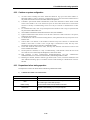
3. General specifications
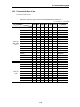
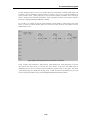
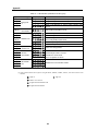
3.2.4 Fnet LED signal name and indication content
Device
type
LED
Name
Meaning of LED indication
RUN
Indicates the status of CPU module and interface
G3L-FUEA
G3L-FUOA
LAS
Indicates that communication module is performing LAS
function.
G4L-FUEA
TOKEN
G6L-FUEA
GOL-FUEA
Tx/Rx
FAULT
RUN
G3L-RBEA
G3L-RBOA
G4L-RBEA
G0L-SMQA
G0L-SMIA
G0L-SMHA
Indicates whether communication module has token or not.
Indicates the status of communication module.
TOKEN
Indicates whether communication module has token or not.
Tx/Rx
Indicates whether communication module is transmitting/
receiving or not.
FAULT
Indicates whether communication error exists or not.
SYS
FAULT
PWR
Indicates whether system error or I/O module error
occurred or not.
Indicates power status.
Indicates Tx/Rx or not of communication module.
ERR
Indicates communication error or not.
LED Off
Normal
Abnormal
In proceeding
Has
Indicates whether communication module is transmitting/
receiving or not.
Indicates the status of communication module.
TRX
LED On
Does not
have
Flicker during
communication
Abnormal
Normal
Normal
Abnormal
Has
Does not
have
Flicker during
communication
Abnormal
Normal
Abnormal
Normal
Power On
Power Off
Flicker during
communication
Abnormal
Normal
* For details on LED, see Appendix A1, LED indication.
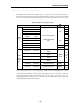
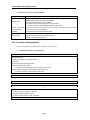
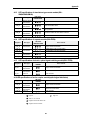
3.2.5 Fnet station number setting
1) Local station number setting
Applied
Device type
Detailed drawing of
station number switch
G3L-FUEA
(1) Station number can be set from 0 to 63(Decimal).
0
G3L-FUOA
G3L-RBEA
×10
7
G3L-RBOA
G4L-FUEA
Description
2
(2) Station number setting
(Factory default is 0)
Switch
5
G4L-RBEA
G0L-SMIA
G0L-SMHA
Sets ten’s figure of station number
X1
Sets one’s figure of station number
0
G6L-FUEA
G0L-FUEA
G0L-SMQA
Setting
X 10
(3) GM6 : The station setting switch is placed in the case.
×1
7
2
5
3-7
3. General specifications
2) Master station number setting
Sets station number of Fnet master module, which can transmit and receive high speed link data in Fnet slave
module(Station number switch is located inside of case).
Applied
Device type
Detailed drawing of
station number switch
Description
(1) Station number can be set from 0 to 63(Decimal).
0
G3L-RBEA
×10
7
(2) Station number setting
(Factory default is 0)
2
G3L-RBOA
Switch
5
Setting
G4L-RBEA
X 10
Sets ten’s figure of station number
G0L-SMQA
G0L-SMIA
X1
Sets one’s figure of station number
G0L-SMHA
0
×1
7
2
5
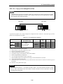
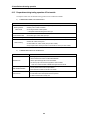
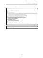
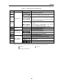
3.2.6 Fnet mode setting
Test mode
Applied
Device type
G3L-FUEA
G3L-FUOA
G3L-RBEA
G3L-RBOA
G0L-FUEA
Detailed drawing
of mode switch
0:ON LINE
1:TEST 1
2:TEST 2
Description
(1) Mode can be set from 0 to 2.
(GM6 : 0 ~ 3)
0
MODE
7
2
5
(2) Mode setting
(Factory default is 0)
Mode
2
ON
0:ON-LINE
1:TEST1
2:TEST2
Function
0
Performs normal operation
1
Sets the unit as data transmitting station in
communication test
2
Sets the unit as data transmitting station in
communication test
MODE
G4L-FUEA
G4L-RBEA
â1
1)
* For details, see chapter 7, Diagnosis function.
3-8
3. General specifications
2) Emergency data output setting
In Fnet slave module, when the communication with remote station is cut off by remote station error or line
error during communication, setting of these switches specifies an operation between latching I/O data in slave
module and outputting optional user-defined data.
Applied
Device type
Detailed drawing
of mode switch
Description
모
Mode
드
1
G3L-RBEA
G3L-RBOA
G4L-RBEA
G0L-SMQA
G0L-SMIA
G0L-SMHA
ON
1
2
2
Latches
the last마지막
data during
communication
error.
통신
에러시
데이터를
래치 시킴.
3
4
3
4
1
기 Function
능
ON
ON
2
3
4
통신
에러시
사용자가
설정한
값을 출력함.
Outputs
user-defined
data during
communication
error (Default is
data reset).
(Default는
데이터
Reset임)
모
Mode
드
1
2
ON
1
ON
2
1
2
ON
기 Function
능
Latches
통신 에러시
the last 마지막
data during
데이터를
communication
래치 error.
시킴.
통신 에러시
사용자가
설정한
값을 출력함.
Outputs
user -defined
data during
communication
error
(Default is데이터
data reset).
(Default는
Reset임)
Remark
1.
2.
All of the switches are set to off by factory default.
User can input user-defined data for communication error in GMWIN function block program.
(Refer to 6.6.7, Setting emergency output data of remote module.)
3-9
3. General specifications
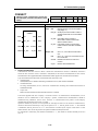
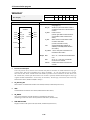
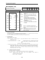
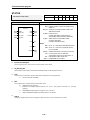
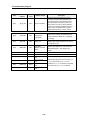
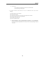
3.2.7 Mnet module structure : G3L-MUEA
G3L-MUEA
Type
형명 name
표시부indicating section
Indicates
type name
of communication
module
통신 모듈의
형명
표시
RUN
TX
RX
IN-RING
FAULT
LED표시부
indicating section
LED
RUN
RUN
Indicates
the status
of CPU module
interface
CPU 모듈과
인터페이스
상태and표시
TX
TX
Indicates
통신 모듈의
data and데이터
token transmission
및 토큰 송신
of communication
표시
module
RX
RX
Indicates
data and데이터
token receive
of communication
통신 모듈의
및 토큰
수신 표시 module
Turns
lamp on
if operating
2대 the
이상의
통신
모듈이communication
동작중일 때module
점등 is two or more, and
IN
RING
IN-RING
flashes if operating module is just one
×10
1대만이 동작할 때에는 점멸
×1
FAULT
FAULT
Flickers
the 정상적으로
error that normal
operation
not possible
통신 when
모듈에
기동할
수is없는
에러 occurred in
communication
module
발생 시 점멸
MODE
Station number setting switch
0:ON-LINE
1:P/M SETTING
2:TEST1
3:TEST2
국번
설정 스위치
Sets station number in the range of 0~63 station(St in decimal).
0~63국 사이의 범위 설정(10진수로 설정)
Mode setting switch
모드
설정 스위치
Sets operation mode of communication module
통신 모듈의 동작 모드 설정
통신 커넥터 connector
Communication
Connector
for coaxial
cable connection
to connect 접속용
communication
통신 모듈을
연결하기
위한 동축케이블
커넥터module.
Mode setting
Applied
device type
Detailed drawing
of mode switch
Description
(1) Mode can be set from 0 to 2.
G3L-MUEA
G0L-MUEA
MODE
0:ON LINE
1:P/M SETTING
2:TEST1
3:TEST2
(2) Mode setting
(Default is 0)
0
7
2
5
3-10
Mode
0
Function
Performs normal operation
1
Used for parameter setting of GMWIN
2
3
Sets when communication module is tested
Reservation(presently not available)
3. General specifications
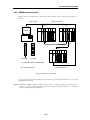
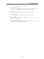
3.2.8 Mnet computer interface module structure : GOL-MUEA
④
X1
X10
⑦
①
②
⑥
PORT
ADDRESS
③
1
2
4
3
5
⑤
①
0
01
1
2
2
3
3
44
②
Port
Address
포트선택 주소선택
select-i
select-io
on
n
3E0
FC00
3E0
FC00
3C0
F800
3C0
F800
3A0
F400
3A0
F400
380
F000
380
F000
360
EC00
360
EC00
55
340
340
E800
E800
66
320
320
E400
E400
77
8
8
9
9
A
BA
300
300
2E0
2E0
2C0
2C0
2A0
2A0
280
E000
E000
DC00
DC00
D800
D800
D400
D400
D000
B
C
280
260
D000
CC00
C
D
260
240
C800
CC00
ED
FE
220
240
200
220
C400
C800
C000
C400
F
200
C000
③
LED indicating section
LED 표시부
No.1
RUN
Indicates the status of IBM compatible PC and interface
1번
RUN
IBM Indicates
호환 PC와
인터페이스
표시
data
and token 상태
transmission
of communication
No.2
TX
module
2번
TX
통신 모듈의 데이터 및 토큰 송신중임을 표시
Indicates data and token receive of communication
No.3
RX
3번
RX
통신module
모듈의 데이터 및 토큰 수신중임을 표시
IN-RIN2대 Lights
if operating
module is two or
이상의on통신
모듈이 communication
동작중일 때 점등
No.4
4번 IN-RING
G 1대만이
more,동작할
and flashes
if operating
module is just one
때에는
점멸
when the error that normal operation is not
No.5 FAULT
FAULT통신Flashes
5번
모듈에 occurred
정상적으로
기동할 수 없는
에러 발생시 점멸
possible
in communication
module
④
국번
Station
설정number
스위치 setting switch
0~63국
Sets
station
사이의
number
범위를
in the
설정.(10진수로
range of 0~63 station(Set
설정)
in decimal).
⑤
Mode
setting
모드
설정
스위치switch
Sets
mode
of communication
module(see
통신 operation
모듈의 동작
모드
설정(3.2.7 G3L-MUEA
모드 3.2.7
설정 G3L-MUEA
참조)
structure)
⑥
⑦
Reset 스위치
Reset switch
통신 모듈을 초기화 시켜주기 위한 스위치
A switch to initialize communication module
통신 커넥터
Communication connector
통신 모듈을 연결하기 위한 동축케이블 접속용 커넥터
Connector for coaxial cable connection to connect communication module.
Remark
1.
2.
Port is set to No.5(340) and address is set to No.9(D800) by factory default.
This should be set in order not to be duplicated with other device area previously used, and add
DEVICE=C:\WINDOWS\EMM386.EXE NOEMS X=D800- D8FF(if address has been set to No.9(D800))
in CONFIG.SYS to use set area for not continuous or extended area of computer but this module.
3-11
4. Transmission specifications
Chapter 4 Transmission specifications
4.1
Transmission specifications of Fnet
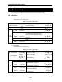
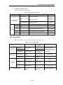
4.1.1 Transmission specifications of Fnet master module
Product of Fnet master module : G3L-FUEA, G3L-FUOA, G4L-FUEA, G5L-FUEA, G6L-FUEA, G0L-FUEA
Table 4.1.1 Transmission specifications of Fnet master module
Item
Specification
Transmission speed
1Mbps
common in Fnet module
Encoding type
Manchester Biphase-L
Transmission distance
Max. 750m
(per segment)
Electric
Transmission distance
(during using repeater)
Max. 750m × (6 repeater + 1) = 5.25 km
Transmission line
Twisted pair shielded cable
Transmission distance
Max. 3km
(per segment)
Optical
Transmission distance
Max. 3km × (6 EOC +1) = 21km
(during using EOC)
Transmission line
Optical cable
Max. number of station connection
Master + slave = 64 station
(At least one master should be connected)
Max. size of protocol
256 byte
Access type of
Circulated token passing
communication right
Communication type
Connection oriented service
Connectionless service
Frame error check
CRC 16 = X + X + X + ... + X + X + 1
15
4-1
14
13
2
4. Transmission specifications
4.1.2 Transmission specifications of Fnet slave module
Product of Fnet slave module : G3L-RBEA, G3L-RBOA, G4L-RBEA, G0L-SMQA, G0L-SMIA,
G0L-SMHA
Table 4.1.2 Transmission specifications of Fnet slave module
Item
Specification
Transmission speed
1Mbps
Encoding type
Manchester Biphase-L
Transmission distance
(per segment)
Electric
Max. 750m
Transmission distance
Max. 750m × (6 repeater + 1) = 5.25km
(during using repeater)
Optical
Transmission line
Twisted pair shielded cable
Transmission distance
(during segment)
Max. 3km × (6 EOC +1) = 21km
Transmission line
Optical cable
Max. number of stations connected
Link master class + Remote slave class = 64
Max. size of protocol
256 byte
Access type of
Circulated token passing
communication right
Connection oriented service
Connectionless service
Communication type
4.1.3 Transmission specifications of Fnet option module
Product of Fnet option module : G0L-FREA, G0L-FOEA, G0L-FACA
1)
Repeater (G0L-FREA)
Table 4.1.3(A) Transmission specifications of repeater
Item
Specification
Communication speed
1Mbps
Encoding type
Manchester Biphase-L
Transmission line(Cable)
Twisted pair shielded cable
Max. extension distance per module
750m
Max. number of repeater between
stations
6 units
Max. distance between stations
5.25km(when 6 repeater is installed)
Frame error check
CRC 16 = X + X + X + ... + X + X + 1
15
4-2
14
13
2
4. Transmission specifications
2)
Electric/Optical converter (G0L-FOEA)
Table 4.1.3(B) Transmission specifications of electric/optical converter
Item
Specification
Communication speed
1Mbps
Encoding type
Manchester Biphase-L
Transmission line(Cable)
Optical cable, twist pair cable
Max. transmission distance
3km(Optical)/750m(electric)
Function of signal regeneration
Regenerating, Reshaping function
Frame error check
CRC 16 = X + X + X + ... + X + X + 1
3)
15
14
13
2
Active coupler (Product : G0L-FACA)
Table 4.1.3(C) Transmission specification of active coupler
Item
Specification
Communication speed
1Mbps
Encoding type
Manchester Biphase-L
Transmission line(Cable)
Optical cable
Max. transmission distance
3km
Function of signal regeneration
Regenerating, Reshaping function
Frame error check
CRC 16 = X15 + X14 + X13 + ... + X2 + X + 1
4-3
4. Transmission specifications
4.2
Transmission specifications of Mnet
Table 4.2 Transmission specification of Mnet
Item
Communication line
Max. number of
stations connected
Specification
75Ω coaxial cable (RG-6 / RG-11)
Max. 64 station
Communication speed
5 Mbps
Connection connector
75Ω female F series
Modulation type
Transmission distance
Max. protocol length
Error detection
Access type of communication right
Phase lock FSK (Frequency Shift Keying)
Max. 900m
1 kbyte
FCS(CRC 32 type)
Token passing bus type
4-4
4. Transmission specifications
4.3
Cable specifications
4.3.1 Twisted pair cable for Fnet
Type name of product :
G0C-T□□□ (□□□ is length of cable, unit : m)
Ex.) Twisted pair cable 10m : G0C-T010
Table 4.3.1 Specifications of twisted pair cable for Fnet
Cable contents
Product name
Low Capacitance LAN Interface Cable
Type name
LIREV-AMESB
Size
2 × 1.0mm (GS 92-3032, 18 AWG)
Maker
LG CABLE CO.,LTD
Electric characteristics
Item
Unit
Characteristic
Test Condition
Conductor resistance
Ω/km
21.8 or less
Normal Temp.
Withstanding voltage(DC)
V/min
Withstands at 500V for 1 minute
In air
Insulation resistance
MEGA Ω-km
1,000 or more
Normal Temp.
Static electricity capacity
pF/m
45 or less
1 kHz
Characteristic impedance
Ω
120 ± 12
10 MHz
Characteristics in appearance
Conductor
Insulator
l
Number of core
CORE
2
Specification
AWG
18
Configuration
NO./mm
1/1.0
Outer diameter
mm
1.0
Thickness
mm
0.9
Outer diameter
mm
2.8
Structural drawing
Conductor
Insulator
AL/Mylar Tape
Ground line
Braided
material
Sheath material
4-5
4. Transmission specifications
4.3.2 Optical cable for Fnet
Type name :
G0C-F□□□ (□□□ is length of cable, unit : m)
Ex.) Optical cable 10m : G0C-F010
Table 4.3.2 Specifications of optical cable
Cable contents
Type name
Y22□□□□ : For indoor (for Bi-directional communication)
D22□□□□ : For outdoor (for Bi-directional communication)
Connector type
ST - Type
Maker
Hewlett Packard(H.P)
Segment
For indoor(standard)
For outdoor(standard)
Y22□□□□
D22□□□□
2.9 × 5.8
4.8
Loaded (cm)
5.0
7.5
Unloaded (cm)
Outer diameter (mm)
Min. Radius
of curvature
3.0
4.8
Weight(Kg/m)
16
21
Contents
Characteristic
Unit
Core
62.5
µm
Cladding
125
µm
Max. attenuation
5
dB/km
Standard attenuation
4.5
dB/km
※
□□ □□
69 : Stainless
Connector
type
커넥터 타입
09 : Ceramic
Connector
type
커넥터 타입
Ex.) If the
cable type
is Y226969,
type is ST양측
and the
예) 케이블
타입이
이면 connector
표준 옥내용으로
커넥터
Y226969
shape is stainless at both of the connectors.
타입이 ST, 형태는 Stainless
l Outside drawing of optical cable
For indoor(Y22□□□□)
For outdoor(D22□□□□)
4-6
4. Transmission specifications
4.3.3 Coaxial cable for Mnet
1)
Cable
When network is configured using Mnet communication module, RG-6(Drop cable) and
RG-11(Trunk cable) which conform to IEEE 802.4 Carrier Band can be used. The following is
specifications for RELCOM(USA) company product, so user may refer to the following.
Table 4.3.3(A) Cable specifications available in Mnet
Attenuation distortion
(dB/100m)
Type
Distance(m)
Transmitting impedance
10MHz
20MHz
5Mbps
10Mbps
Milli-ohm/meter max
RG-6(Drop) standard 5750
2.47
3.12
818
538
10
RG-11(Trunk) standard 5950
1.46
2.05
960
717
10
2)
Tap
Tap is used to connect and to branch each station with trunk cable, and electric characteristic of Tap
should be outstanding, and comply with specifications. The following is specifications of Tap(2-port
and 4-port Tap) for RELCOM(USA) company product, so user may refer to the following.
Table 4.3.3(B) Tap specifications available in Mnet MCM group
Electric characteristic
CBT-2(2-port)
CBT-4(4-port)
Unit
Trunk to drop attenuation&distortion
20 ± 0.5
20 ± 0.5
dB min.
Trunk return loss
35
35
dB min.
Drop return loss
20
20
dB min.
Drop to drop Isolation
30
30
dB min.
Additional loss
0.3
0.5
dB min.
4-7
4. Transmission specifications
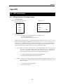
4.4
How to connect communication cable
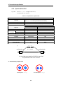
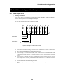
4.4.1 Electric(twisted pair) cable connection
Cable for electric network connection uses only No.6 and No.7 of the connector pin, No.6 signal of
communication module connector A is connected to No.6 of communication connector B, and No.7 of
connector A is connected to No.7 of connector B. Body of connector(metal : electrically conductive) is
connected with other module by shielding wire, and bypasses external noise, etc., so connector of both side
should be connected with shielding wire, and contact with high voltage and high current should not be
allowed. For treating shielding wire in connection of G0L-FUEA(PC attached Fnet module) connector,
general communication module body must be connected with pin No.5 of G0L-FUEA like Figure 4.4.1.
Shield wire
6
6
7
7
5
6
7
Shield wire
<Communication module A>
<Communication module B>
<Communication module>
6
7
<G0L-FUEA>
(Verify pin No. marked in connector to connect)
Fig. 4.4.1 Cable connection method of Fnet
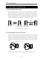
4.4.2 Electric(twisted pair) cable connector connection
Connector is accessory parts which connects electric network of fieldbus module, and it should be
connected as a method in Figure 4.4.2(A). It should be noted that shielding wire of cable should be
connected to metal part of connector by soldering, and the other. Data transmission/receive is impossible if
shielding wire is not connected(Shielding wire of G0L-FUEA should be connected to No.5 pin as shown in
Fig.4.4.2(B) to prevent contact with computer body. Internally No.5 pin CON1 And CON2 are under short,
so shielding wire is separated from computer body, and it is bypassed next connection station or terminal
resistance).
Shielding wire(soldered)
Pin No.7
Pin No.7
Pin
No.6
Pin
No.6
Shielding
wire
Pin No.5
9-pin socket type
Fig. 4.4.2(A) Connection of Fnet connector
9-pin socket type
Fig. 4.4.2(B) Connection of G0L-FUEA connector
4-8
4. Transmission specifications
4.4.3 Optical cable connection
Optical cable is connected by crossing transmission and receive line, i.e., RX of optical communication
module A is connected to TX of optical communication module B, and TX of optical communication
module A is connected to RX of optical communication module B.
TX (Trans mission)
TX (Transmission)
RX (Receive)
RX (Receive)
<Station A>
4.5
<Station B>
Terminal resistance
4.5.1 Electric network terminal resistance of Fnet
l
Resistance : 110Ω , 1/2 W
l
Connector case : Metal conductor plating type
7 번No.7
핀
Pin
Pin
6번 핀
No.6
Terminal
종단 저항
resistance
9-pin
9핀
socket
Socket
type Type
è
Terminal resistance(110 Ω, 1/2W) of accessory parts(electric module only) should be
attached at the start and end of network.
è
Terminal resistance is attached inside of electric/optical converter(G0L-FOEA) and
repeater(G0L-FREA) which are installed at terminal of electric network. Therefore, do not
connect terminal resistance separately from external.
è
Connector case should not be connected with terminal resistance.
4-9
4. Transmission specifications
4.5.2 Terminal resistance of Mnet
l
Resistance : 75 Ω, 1/4 W
l
Outside drawing of Mnet terminal resistance and TAB
Drop port
Ex. of 4 port TAB
Terminal
resistance 75Ω
Terminal
resistance 75Ω
Max. 700m
Trunk cable
Drop cable
Trunk port
Max. 50m
PLC Mnet connection
PLC Mnet connection
4-10
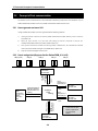
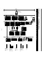
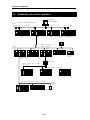
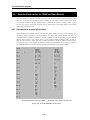
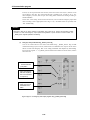
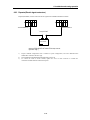
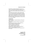
Mnet(5Mbps,64stations ,900m,Coaxial Cable)
Fnet Board
(GOL-FUEA)
GMWIN
GM1
GM2
FAM
GM3
RS-232C
Fnet(1Mbps,64stations ,750m,Twisted pair cable )
Repeater
(GOL-FREA)
GM6
GM1
GM2
GM4
GM3
GM5
GM3 remote I/O
(GM3-RBOA)
5-1
Stand-alone
remote I/O
(GOL-SMQA)
Active coupler
Electric/optical
Converter(GOL-FOEA)
GM2
GM1
GM3
Fnet(1Mbps,64stations ,750m,Twisted pair cable )
GM3 remote I/O
GM4 remote I/O
GM4 remote I/O
Optical Cable
G3L-MUEA
GLOFA-GM1,2,3 PLC
Electrical comm.
module
G3L-FUEA,G4L-FUEA
G6L-FUEA,G5L-FUEA
GLOFA-GM1,2,3,4,5
Master comm. modules
G3L-FUOA
GLOFA-GM1,2,3
Optical comm.
module
G3L-RBEA, G4L-RBEA
GLOFA-GM1,2,3,4
Slave communication
module
Electric/optical
converter
G3L-RBOA
5. System Configuration
Stand-alone
remote I/O
GM4 remote I/O
GLOFA PLC network system(entire system)
FAM(FA Manager)
Mnet Board(GOL-MUEA)
Chapter 5 Configuration
5.1
ETHERNET
5. System configuration
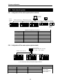
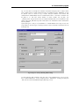
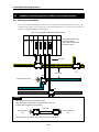
5.2
Fnet network system
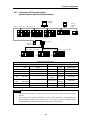
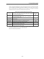
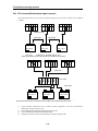
5.2.1 Configuration of Fnet master system (electric network)
FAM
Terminal
resistance
110ohm
Fnet Board
(GOL-FUEA)
PMU
Network A (Fnet electric ,1Mbps,64 stations, 750m)
GM1
GM2
GM5
GM3
GM4 (GM6)
Terminal
resistance
110ohm
Devices for network A (Fnet electric)
Type
Module name
Ex. of station number setting
FAM4.0
G0L-FUEA
0
GM1
G3L-FUEA
1
GM2
G3L-FUEA
2
GM3
G3L-FUEA
3
GM4 (GM6)
G4L-FUEA (G6L-FUEA)
4
GM5
G5L-FUEA
5
PMU-500
PM0-500F
6
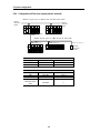
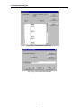
5.2.2 Configuration of Fnet master system (optical network)
Active coupler
(GOL-FAPA + GOL-FABA + GOL-FACA
=> power + base + module)
Network A (Fnet,optical)
GM1
GM2
GM3
※ For unused slot, dummy module(G0L-FADA) is attached.
Devices for network A (Fnet optical)
Type
Module name
Ex. of station number setting
GM1
G3L-FUOA
0
TransmissionàReceive
GM2
G3L-FUOA
1
(Active coupler)
GM3
G3L-FUOA
2
Active coupler
G0L-FACA/FABA/FAPA
Not available
ReceiveàTransmission
(Active coupler)
5-2
Cable connection
5. System configuration
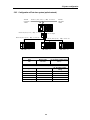
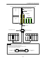
5.2.3 Configuration of Fnet master system
(network combined with electric/optical module)
Fnet Board
(GOL-FUEA)
FAM
PMU
Network A (Fnet,electric), 1Mbps, 64 stations
Terminal
resistance
110ohm
GM5
GM4 (GM6)
GM1
GM2
GM3
Network A (Fnet,optical) 1Mbps
Active coupler
Electric/optical
converter (GOL-FOEA)
Network A (Fnet,optical) 1Mbps
GM1
Network A (Fnet,optical) 1Mbps
Network A (Fnet,optical) 1Mbps
GM3
GM2
Devices for network A (Fnet)
Electric
Optical
Type
Module
name
FAM
G0L-FUEA
0
GM1
G3L-FUOA
7
GM1
G3L-FUEA
1(slot 0)
GM2
G3L-FUOA
8
GM2
G3L-FUEA
2
GM3
G3L-FUOA
9
3
Optical/electric
converter
G0L-FOEA
Not available
4
Active coupler
G0L-FACA
(Remark)
Not available
GM3
G3L-FUEA
Ex. of station number
setting
GM4
G4L-FUEA
(GM6)
(G6L-FUEA)
GM5
G5L-FUEA
5
PMU-500
PM0-500F
6
Type
Module
name
Ex. of station
number setting
Remark
1.
2.
Separate terminal resistance is unnecessary due to terminal resistance built- in inside optical/electric
converter.
Active coupler used in system configuration is consist of G0L- FAPA(Power), G0L- FABA(Base) and
G0L- FACA( Module). Module can be mounted up to 8 in the base, and dummy module(G0L-FADA)
should be attached for unused base to protect from foreign matter, dust, and the others.
5-3
5. System configuration
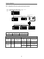
5.2.4 Configuration of Fnet slave system (electric network)
Network A (Fnet,electric) 1Mbps,64 stations,Twisted Pair Cable
Terminal
resistance
110ohm
Terminal
resistance
110ohm
GM2
Terminal resistance
110ohm
GM3
Network B (Fnet,electric) 1Mbps,64 stations,Twisted Pair
Cable
GM3 remote I/O
Stand-alone remote I/O
GM4 remote I/O
Terminal
resistance
110ohm
Devices for network A (Fnet electric)
Type
Module name
Ex. of station number setting
GM2
G3L-FUEA
0(slot 0)
GM3
G3L-FUEA
2(slot 0)
Devices for network B (Fnet electric)
Type
Module name
Ex. of station number setting
GM2
G3L-FUEA
1(slot 1)
GM3 remote I/O
G3L-RBEA
3
GM4 remote I/O
G4L-RBEA
4
Stand-alone remote
output
G0L-SMQA
5
5-4
5. System configuration
5.2.5 Configuration of Fnet slave system (optical network)
Terminal
resistance
110ohm
Network A (Fnet ,electric), 1Mbps, 64 stations
GM2
Terminal
resistance
110ohm
Network B (Fnet ,optical), 1Mbps, 64 stations
Active coupler
Network B (Fnet ,optical), 1Mbps, 64 stations
Network B (Fnet ,optical), 1Mbps, 64 stations
GM3 remote I/O
GM3 remote I/O
GM3 remote I/O
Devices for network A (Fnet ,electric)
Type
Module name
Ex. of station number setting
GM2
G3L-FUEA
0(slot 0)
Devices for network B (Fnet ,optical)
Type
Module name
Ex. Of station number
setting
GM2
G3L-FUOA
1(slot 1)
GM3 remote I/O
G3L-RBOA
2
GM3 remote I/O
G3L-RBOA
3
GM3 remote I/O
G3L-RBOA
4
Active coupler
G0L-FACA/FABA/FAPA
Not available
5-5
5. System configuration
5.2.6 Configuration of Fnet slave system (electric/optical network)
Network A ( Fnet,electric), 1Mbps, 64 stations
Terminal
resistance
110ohm
Terminal resistance
110ohm
Terminal resistance 110ohm
GM2
Network B ( Fnet,electric), 1Mbps, 64 stations
Stand-alone remote I/O
(GOL-SMQA)
Electric/optical
converter
GM4 remote
GM3 remote
Active coupler
Network B ( Fnet,optical), 1Mbps, 64 stations
GM3 remote I/O
GM3 remote I/O
GM3 remote I/O
Devices for network A (Fnet electric)
Type
Module name
Ex. of station number setting
GM2
G3L-FUEA
0(slot 0)
Devices for network B (Fnet)
Electric
Optical
Type
Module
name
Ex. of station
number setting
Type
Module
name
Ex. of station
number setting
GM2
G3L-FUEA
1(slot 0)
GM3 remote I/O
G3L-RBOA
5
GK3 remote I/O
G3L-RBEA
2
GM3 remote I/O
G3L-RBOA
6
GK3 remote I/O
G4L-RBEA
3
GM3 remote I/O
G3L-RBOA
7
Electric/optical
converter
G0L-FOEA
Not available
Stand-alone
remote output
G0L-SMQA
4
Active coupler
5-6
G0L-FACA/
FABA/FAPA
Not available
5. System configuration
5.2.7 Configuration of Fnet combined system (electric/optical network)
Fnet Board
(GOL-FUEA)
FAM
PMU
Network A (Fnet,electric) 1Mbps, 64 stations
Terminal
resistance
110ohm
GM1
GM2
GM5
GM3
GM4 (GM6)
Terminal
resistance
110ohm
Terminal
resistance
110ohm
Active coupler
Network B (Fnet,optical) 1Mbps, 64 stations
GM3 remote I/O
GM3 remote I/O
GM3 remote I/O
Network C (Fnet,electric) 1Mbps, 64 stations
Terminal
resistance
110ohm
Stand-alone remote I/O
GM4 remote I/O
GM3 remote I/O
5-7
5. System configuration
Devices for network A (Fnet, electric)
Type
Module name
Ex. of station number setting
FAM
G0L-FUEA
0
GM1
G3L-FUEA
1(slot 0)
GM2
GM3
G3L-FUEA
G3L-FUEA
3
4
GM4 (GM6)
G4L-FUEA (G6L-FUEA)
6
GM5
G5L-FUEA
7
PMU-500
PM0-500F
8
Devices for network B (Fnet ,optical)
Type
Module name
Ex. of station number setting
GM3
G0L-FUOA
5(slot 1)
GM3 remote I/O
G3L-RBOA
12
GM3 remote I/O
G3L-RBOA
13
GM3 remote I/O
G3L-RBOA
14
Active coupler
G0L-FACA/FABA/FAP
A
Not available
Devices for network C (Fnet ,electric)
Type
Module name
Ex. of station number setting
GM1
G3L-FUEA
2(slot 1)
GM3 remote I/O
G3L-RBEA
9
GM4 remote I/O
G4L-RBEA
10
Stand-alone remote
output
G0L-SMQA
11
5-8
5. System configuration
5.3
Mnet network system
5.3.1 System configuration of Mnet
FAM(FA Manager)
Mnet Board(GOL-MUEA)
Network A Mnet(5Mbps,64stations)
Terminal
resistance
75ohm
TAP
TAP
Terminal
resistance
75 ohm
Trunk cable
Drop cable
GM1
GM2
GM3
Devices for network A (Mnet)
Type
Module name
Ex. of HS station
number setting
Ex. of MAC station number
FAM
G0L-MUEA
0
16# 00E091000000
GM1
G3L-MUEA
1
16# 00E091000001
GM2
G3L-MUEA
2
16# 00E091000002
GM3
G3L-MUEA
3
16# 00E091000003
5.3.2 System configuration of Mnet (including other company's product - Ex.
GOLDSEC-M series)
FAM(FA Manager)
Mnet Board(GOL-MUEA)
Terminal
resistance
TAP
75ohm
Network A Mnet(5Mbps,64stations)
TAP
Trunk cable
TAP
Drop cable
GM1
GM2
GM3
Terminal
resistance
75 ohm
PLC of other company : Ex. GOLDSEC-M series
Devices for network A (Mnet)
Ex. of station number setting for
high speed link communication
Ex. of MAC station number for
function block communication
G0L-MUEA
0
16# 00E091000000
G3L-MUEA
1
16# 00E091000001
G3L-MUEA
2
16# 00E091000002
Type
Module name
FAM
GM1
GM2
GM3
G3L-MUEA
3
16# 00E091000003
Other Company
MJ71M51CM1
Not available
16# 1200F2243202
5-9
5. System configuration
5.4
Combined system of Fnet and Mnet
FAM(FA Manager)
Mnet Board(GOL-MUEA)
Terminal
resistance
75ohm
Network A Mnet(5Mbps,64stations)
TAP
T runk cable
TAP
TAP
GM3
PLC of other company : Ex. GOLDSEC-M series
Terminal
resistance
75 ohm
Drop cable
GM1
GM2
PMU
Terminal
resistance
110 ohm
N e t w o r k B ( F n e t ,e l e c t r i c )
1Mbps, 64 stations
GM1
GM2
GM4 (GM6)
GM3
G M5
Terminal
resistance
110 ohm
Terminal
resistance
110 ohm
Active coupler
Network D (Fnet,electric) 1Mbps,
64 stations
GM3 remote I/O
GM3 remote I/O
GM3 remote I/O
Network C ( Fnet optical) 1Mbps, 64 stations
Terminal
resistance
110 ohm
Stand-alone remote
G m4 remote I/O
GM3 remote I/O
5-10
5. System configuration
Devices for network A (Mnet)
Type
Module name
Ex. of HS station number
setting
Ex. of MAC station number
FAM4.0
G0L-MUEA
0
16# 00E091000000
GM1
G3L-MUEA
1
16# 00E091000001
GM2
G3L-MUEA
3(slot 0)
16# 00E091000002
GM3
G3L-MUEA
4
16# 00E091000003
Other company
MJ71M51CM1
5
16# 1200F2249A04
Devices for network B (Fnet, electric)
Type
Module name
Ex. of station number setting
GM2 of network A
G3L-FUEA
2(slot 1)
GM1
G3L-FUEA
6(slot 0)
GM2
G3L-FUEA
9
GM3
G3L-FUEA
11(slot 0)
GM4
G4L-FUEA
(GM6)
(G6L-FUEA)
GM5
G5L-FUEA
13
PMU-500
PM0-500F
14
12
Devices for network C (Fnet, electric)
Type
Module name
Ex. of station number setting
GM1 of network B
G3L-FUEA
7(slot 1)
GM3 remote I/O
G3L-RBEA
15
GM4 remote I/O
G4L-RBEA
16
Stand-alone remote
output
G0L-SMQA
17
Devices for network D (Fnet, optical)
Type
Module name
Ex. of station number setting
GM3 of network B
G3L-FUOA
10(slot 1)
GM3 remote I/O
G3L-RBOA
18
GM3 remote I/O
G3L-RBOA
19
GM3 remote I/O
G3L-RBOA
20
Active coupler
G0L-FACA
Not available
5-11
6. Communication program
Chapter 6
6.1
Communication program
Programming method
In Mnet and Fnet communication module, programming methods are divided into three :
–
High speed link
High speed link is used when other station’s data or information is exchanged in each given
time and cyclically. Self or other station’s data being in changing can be effectively used for
operating system through cyclically referring, and the communication can be performed only
through setting parameters.
For how to set, specify other station area and self area to be se nt/received in parameter of
GMWIN, specify data size, speed, and station number, and then perform communication.
For data size, 1(16 points )~12,800 words for Mnet, and 1~3,840 words for Fnet can be
communicated, and for communication cycle, 20ms~10sec. can be set according to
communicating contents. Because simple parameter setting enables communication with
other station, it is easy to use, and internal data processing is also high speed, thus many
data can be cyclically processed at a time.
–
Function block
High speed link is a cyclic communication, but the communication through function block is a
service that communicates when special event occurs to perform communication with other
station. Function block can be used when other station has error, which is sent to another
station, or special contact is entered to communicate. For how to prepare programming,
using function block according to data type previously created in GMWIN program mode,
specify the enable conditions, the module position in which communication module is
mounted, station number, data area of self station, and other station area, and then prepare
it. High speed link has unit of word(16 points) as data size, but function block has Bit, Byte,
and Word, etc. as data size depending on data type to communicate with other station.
–
Simultaneous use of high speed link and function block
For some data, high speed link and function block can be simultaneously used for program
when the appropriate contents is sent if Tx/Rx of data are cyclically performed, and special
event occurs.
6-1
6. Communication program
Table 6.1 Difference between high speed link operation and operation through function block
Contents
High speed link
Function block
1 word(16 points)
Available according to data type
Ex.) Bi t, Byte, Word…
Communication cycle
20ms~10sec.
Used whenever function
condit -ion is started up.
Module available for
communication
Used between Mnet/Fnet GLOFA
communication modules
Used for communication with Mnet/Fnet
communication module and other company’s
communication module(Mini-Map only).
Specifying station
number
Used by setting station number of the
front of communication module in
parameter
Fnet uses the station number of the front of
communication module, and Mnet uses MAC
addres s.
How to operate
Parameter settingàdownloading to
PLCàhigh speed link allowedàRUN
Compilingàdownloading to PLCàRUN
Used if high speed link is allowed even in
state that CPU module is RUN, STOP,
and PAUSE.
Performs operation according to key status of
CPU module.
Basic unit of Tx/Rx
data
Control through CPU
operation mode key
6.2
block
enable
High speed link
6.2.1 Introduction
High speed link is a communication service which transmits data by setting link parameter, and a
high speed data transmitting service that can exchange data through setting size of
Tx/Rx(Transmission and Receive) data, period of Tx/Rx, area of Tx/Rx, and area of storage with
high speed link parameters of GMWIN.
–
Function of high speed link block setting :
1)
2)
3)
–
If there are many Tx/Rx areas, Max. 64 blocks of each 32 of Tx/Rx can be set.
Mnet module can be set up to 200 words and Fnet can be set up to 60 words per block.
Max. link point can be used up to 12,800 words in Mnet module, and 3,840 words in
Fnet module.
Function of Tx/Rx period setting :
User can set the period of Tx/Rx according to each block, and the period of Tx/Rx can be set
from 20ms to 10sec according to the area that quick Tx/Rx is specially needed or not.
–
Function of Tx/Rx area setting :
Tx/Rx area can be set according to data block in GMWIN depending on user’s I/O.
6-2
6. Communication program
–
Function of high speed link information providing :
High speed link information is provided to user through GMWIN user keyword, so reliable
communication system can be constructed easily.
Table 6.2.1 Max. high speed link points according to device type
Max. number of
points for
communication
Max. number
of points for
transmission
Max.
block
number
Max. number
of points per
block
G3L-MUEA
12,800 word
6,400 word
64(0~63)
200 word
G0L-MUEA
12,800 word
6,400 word
64(0~63)
200 word
G3L-FUEA/FUOA
3,840 word
1,920 word
64(0~63)
60 word
G3L-RBEA/RBOA
3,840 word
1,920 word
64(0~63)
60 word
Segments
Mnet
communication module
Fnet
communication module
G4L-FUEA
3,840 word
1,920 word
64(0~63)
60 word
G4L-RBEA
3,840 word
1,920 word
64(0~63)
60 word
G5L-FUEA
3,840 word
1,920 word
64(0~63)
60 word
G0L-FUEA
3,840 word
1,920 word
64(0~63)
60 word
G6L-FUEA
3,840 word
1,920 word
64(0~63)
60 word
Remark
Identical
value for
electric/
optical
6.2.2 Tx/Rx data processing of high speed link
Tx/Rx data processing in high speed link can be described as follows(Ex. of local
communication) :
Ex.) When A station sends %MW0 data, and B station receives the
data %MW0 from A station and stores it to %MW100 of B
station.
In high speed link parameter, there are each 32 block numbers for transmission and receive that
is used to send/receive data, block number can be specified from 0 to 63 to use for transmission
or receive. When sending data, the sending side may determine only which data is r ead and what
number of block the data is sent to. The other station number, therefore, is unnecessary to be
specified(excluding remote communication). Here, it is supposed that A station parameter has
data %MW0 as area to be read, mode is transmission, and block number is optional No.5.
Because the receive side(B station) has to receive the data of the A station that is sending
data %MW0 through block number No.5, the B station high speed link parameter must have the
mode set to receive, the station number set to A, the block number 5, and storing area %MW100.
As a caution, receive side must receive data through the same block number as the number sent
from sending side. Sending side can use various block numbers through various station numbers
to send data, so verify which data is sent and what number of block the data is sent to, and
receive the data through the corresponding block number. Only if so, the required data can be
received.
Station A(sending side)
Station type
: Local
Mode
: Transmission
Block number
:5
Station B(receive side)
Station type
: Local
Block 5 Mode
: Receive
Block number
:5
Area to be read : %MW0
Area to store
: %MW100
Tx/Rx cycle
Tx/Rx cycle
: 200ms
Block 5
Block 5
: 200ms
Size : 1
Size : 1
6-3
6. Communication program
* For communication parameter setting with remote module, see 6.2.4 high speed link parameter setting.
6-4
6. Communication program
6.2.3 Operation procedure by high speed link
Project(parameter)
①
High speed link parameter
High speed link parameter
②
High speed link 1 ~ 4
③
High speed link setting
(link setting)
Network type
Select high speed link parameter in project parameter item of
GMWIN screen
Set to fit to communication module number used.
(If 1 communication module, select 1 high speed link.)
Enter network type, slot number that communication module
is mounted, and self station number with decimal.
• Fnet• Mnet
④
Slot number(0~7)
⑤
Self station number(0-63)
⑥
High speed link setting
(registration list)
Station type
• Local
• Remote
⑦
Station number(0~63)
⑧
Mode
⑨
Block number(0~63)
⑩
Area to be read/storing area
⑪
Tx/Rx period(200ms~10sec)
⑫
Size(1~60 word)
• Sending
• Receive
Online
Writing
⑬
⑭
⑮
• High speed link parameter
When G3L-FUEA/FUOA/MUEA, G4L- FUEA, G6L-FUEA
communication, select local.
When
G3L- RBEA/RBOA/G4L- RBEA/stand- alone remote
communication, select remote.
In case of local connection, select self -station number
(automatically specified) for transmission and select other
station number for receive. In case of remote connection,
select other station number regardless of Tx/Rx.
Each of Tx/Rx can select 32 block numbers. In local
connection, contents of Tx/Rx data can be distinguished and
selected by block number.
For local sending, select reading data of self stat ion, and for
receive, select storing area of self station. For remote, select
reading area to be read of remote station, and for storing
area, select self station area.
If parameter setting finished, carry out compile, and then
per-form writing.
• Parameter and program
Select high speed link parameter or parameter and program
in GMWIN, and download to CPU.
Link allowed setting
High speed link 1-4
Set to link allowed for high speed link operation. When
down-loading program or parameter, previous link allowed
setting is off, so link enable is required.
Switch operation mode to RUN
mode
Other station should be set ①~⑮
(These setting is unnecessary if other
station is remote station).
※ Program using emergency flag, etc. should be prepared
against communication cut-off, error occurrence in other
station, and instant power failure(refer to 6.6 Using
communication module flag).
6-5
6. Communication program
6.2.4 Parameter setting of high speed link
To select high speed link parameter, select link parameter in project screen of GMWIN, and set
appropriate item. Setting sequence and functions according to items are as follows:
1)
Setting project of GMWIN
If high speed link parameter is selected in project bas ic screen of Fig. 6.2.4(A), the high
speed link parameter base screen is opened as Fig. 6.2.4(B), and the appropriate item can
be selected.
Fig. 6.2.4(A)
2)
Bas ic screen of GMWIN project
Selecting link parameter
(1)
How to set : Fig. 6.2.4(B) is setting high speed link parameter in project screen.
Fig. 6.2.4(B) Base screen of high speed link parameter
6-6
6. Communication program
(2)
Setting function : High speed link 1~4 items of Fig. 6.2.4(B) means max. number of
mountable communication modules according to PLC CPU type. GLOFA
GM1/GM2/GM3 CPU are mountable up to 4 units, and GLOFA GM4 is up to 2 units.
A) If 1 communication module is used, select high speed link 1.
B) For one communication module, only one high speed link parameter can be set.
Table 6.2.4(A) shows communication type and max. number of mountable units according to
GLOFA CPU unit.
Table 6.2.4(A) Mounting of communication module according to CPU type
Segments
Communication module
Max. number of
mounting devices
GLOFA-GM1
GLOFA-GM2
G3L-MUEA, G3L-FUEA, G3L-FUOA
4
GLOFA-GM3
3)
GLOFA-GM4
G4L-FUEA
2
GLOFA-GM5
G5L-FUEA
1
GLOFA-GM6
G6L-FUEA
2
Remark
Each of
communication
module can be
combined.
Link parameter setting
If the appropriate parameter is selected in parameter setting base screen of Fig. 6.2.4(B),
high speed link parameter setting window opens as Fig. 6.2.4(C), and the initial values are
displayed as figure when first setting of parameters.
Fig. 6.2.4(C) Initial screen of parameter setting
6-7
6. Communication program
Initial screen of parameter setting is composed of ‘Link setting’ and ‘Registration list’. How to
set and functions are as follows :
(1)
Link setting
Link setting is to set basic items of communication module to perform high speed link .
Fig. 6.2.4(D) High speed link setting screen
Network type : Set communication module type, and select Fnet or Mnet according to
communication module type mounted.
Slot number : Set one of 0~7 for slot number that communication module to moun ted(right
side of CPU module is 0 slot).
Self station : Enter self station number set in station number switch of the front of
communication module. It is decimal, which can be set from 0 to 63. Self station number
is unique number to distinguish communic ation module in the same network system, so
don’t use duplicated station number.
(2)
Registration list setting
Registration list setting is an area to register actual Tx/Rx information of data. Set from
‘0’ that is registration number of registration list area. For this, double click on the
number position to set or select the ‘Modification…’ button to set the appropriate
contents in the modification screen of high speed link item as Fig. 6.2.4(E).
6-8
6. Communication program
(A)
Modification screen of high speed link
Parameter entry number(0~63)
Setting address for sending area
Size of sending data
Means receive block 0
Means LOCAL 0 station
Sending parameter, there is no storing area
(set in receive parameter).
(B) Example of sending parameter setting screen
Fig. 6.2.4(E) Screen of high speed link parameter setting
6-9
6. Communication program
The functions according to each registration item of Fig. 6.2.4(E) are as follows :
–
Registration number : This is serial number indicating the sequence registered, which can be set up
to 64 from 0 to 63, and is regardless of Tx/Rx sequence.
–
Station type : Determines the type of other station to send/receive.
Local type :
G3L-FUEA/FUOA/MUEA. G4 L-FUEA, G5L-FUEA, G6L-FUEA, G0L-FUEA/MUEA,
monitoring interface module and the others.
Remote type : G3L-RBEA/RBOA, G4L-RBEA, Stand-alone remote, and the others.
– Station number : When other station to communicate is local type, set self station number for sending,
and other station number for receiving. When it is remote type, set other station number for both
of Tx/Rx. That is, when high speed link data is sent, don’t specify other station number in order
that data can be received by any receiving station, but when receiving, set other station number
to distinguish the other station of which data is to be received. Because there is no parameter
setting function in remote station itself during communication with remote station, specify
remote station number during Tx/Rx.
* For sending of local type, self station number is automatically set.
Table 6.2.4( B) How to set station number
Station Type
Sending
Receiving
Local
Self station number
Other station number
Remote
Other station number
Other station number
Station number
Range
0 ~ 63(Decimal)
–
Mode : This is an item determining whether data of appropriate block is sent/received. Therefore
select sending for sending, and receiving for receiving. The number of blocks for Tx/Rx can be
set up to 32. So if set to 32 or more, normal communication is impossible due to parameter
error.
–
Block number : This is set to send and receive many data of several area from one station, and
distinguishes data of many blocks each other. Station number and block number configured
from sending station is sent with sending data. If the receive station wants to receive this data, it
must receive the appropriate block number sent from sending station. Number of blocks for
Tx/Rx can be set Max. 32(0~31) for one station. It is impossible that the same block number is
set for the same station number.
–
Area : After selecting data area to send/receive, directly enter and set the address. When the area
th
is %MW, directly enter the word area(Ex. : For 100 word area, select ◉ %MW, and enter 100).
When it is %IW or %QW, after selecting ◉%IW or ◉%QW, directly enter(Ex.: When specifying
st
16 points for the 1 slot of main base, ◉%IW 0.1.0)
6-10
6. Communication program
Local out
: Specifies one of %MW, %IW, %QW for area to read which data of self station is to be
sent.
Local in : Specifies one of %MW, %IW, %QW for storing area of self station that data received from other
station is to be stored.
Remote out : Specifies which data to read in self station(one of %MW, %IW, %QW for area to read), and
which area of remote station to be sent(Only %QW of storing area is able to be specified. That
is, remote sending data can be sent to remote output side only).
Remote in : Specifies one of %MW, %IW, %QW for which area to read in not self station but other
remote station(Only %IW of area to read is able to be specified. That is, only remote input data
can be read.) and which position to store it. Because memory map is different depending to
CPU device type, refer to the memory map specified in the appropriate manual. Settable area
according to station type that has been described as above is shown in Table 6.2.4(C).
Table 6.2.4(C)
Mode
Station type
Local
Remote
Setting area according to station type
Sending
Receive
%IW
%QW
%MW
%IW
%QW
%MW
Area to read
○
○
○
×
×
×
Storing area
×
×
×
○
○
○
Area to read
○
○
○
○
×
×
Storing area
×
○
×
○
○
○
Remark
Area means CPU memory area
○ : Settable
× : Not settable
Remark
For I/O address of stand-alone remote, allocate %IW0.0.0 for input, %QW0.0.0 for output.
– Size :
This means size of Tx/Rx data(unit is 1 word(16 points)). Module type of Fne t system can be set
up to Max.60 word and Mnet system 200 word. If data size configured in receive mode is
smaller than received data size, only the size of data configured in receive mode will be stored
in storing area.
– Tx/Rx period : High speed link executes transmission and receive service when PLC program is
finished by the parameter which user previously configured. If scan time of PLC program is
short(within several ms), communication module transmits data according to program per scan,
and the increase of communication quantity with this causes reduction of entire communication
efficiency. To prevent this, user can set Tx/Rx period from 20ms to 10sec. If there is no setting,
default of 200ms is automatically set. Tx/Rx period means transmission period if appropriate
block is set to transmission, and this means data receive checking period of the appropriate
block if it is set to receive. Transmission period determines data transmission period. If scan
time of PLC program is longer than transmission period previously set, it will be transmitted
when program scan is finished, and transmission period will be the same as scan time of PLC
program(Fig. 6.2.4(F)).
6-11
6. Communication program
PLC program scan time(x)
Set sending period(y)
Sending delay(z)
Sending start
Sending delay time : (z) = (x)-(y) ms
(a) Data sending delay time (PLC program scan time> Sending period)
Set sending period(y)
PLC program scan time(x)
Sending start
Sending delay time : (z) = 0 ms
(b) Data sending delay time(PLC program scan time< Sending period)
Fig. 6.2.4(F) PLC program scan and sending period
Reamrks
When user sets receive period, user must set bigger value than transmission period of other station to check
whether transmission is normal or not.
6.2.5 Operation of High speed link
If high speed link parameter setting is finished, perform parameter writing with PLC CPU after
execution of ‘make’ in compile menu of GMWIN. If, thus, high speed link service is started, high
speed link service starts through parameter setting. The starting sequence of high speed link is
as follows :
6-12
6. Communication program
1)
Parameter writing
Fig. 6.2.5(A)
Screen of parameter download
If high speed link parameter prepared by user is stored to project file of GMWIN, and the writing is
selected after connection with PLC through the on-line connecting of GMWIN basic menu, the
writing window in Fig. 6.2.5(A) is opened. If high speed link parameter or parameter and program is
selected in figure, and parameter downloading is performed, the appropriate contents is downloaded.
At this time, the link enable that is high speed link starting information becomes off. Therefore,
inevitably click on the appropriate item of high speed link 1~4 in link enable setting.
Remark
Before downloading parameter to CPU, carry out compile.
2)
High speed link starting
Fig. 6.2.5(B) Link enable setting
6-12
6. Communication program
Aft er parameter writing, high speed link is maintained to the stop status. Since, thus, user sets link
enable, the high speed link is performed.
Link enable setting is possible in the stop mode of PLC only. Also, if high speed link enable setting is
started, high speed link is performed regardless of PLC operation mode. Parameter and link enable
information are preserved even if power is off due to battery back-up in PLC CPU.
Table 6.2.5 Relation between PLC mode and high speed link
PLC RUN
Parameter
downloading
×
Link enable
setting
×
High speed link
operation
○
PLC STOP
○
○
○
PLC PAUSE
×
×
○
PLC DEBUG
×
×
○
Segment
Remark
Only if high speed
link enable, it is
operated.
6.2.6 Relation between high speed link and CPU mode switch
Once high speed link enable setting is started, the high speed link performs the high speed link regardless of
PLC operation mode. Therefore, output data can not be controlled by operation of other station or self
station mode switch if data is sent from parameter Tx/Rx area to direct output(%Q area) through the high
speed link. To control it, data from other station must be received into %M area, and this data must become
output. Thus controlling by mode switch becomes possible.
6-13
6. Communication program
6.2.7 Communication status information of high speed link
1)
High speed link information function
To confirm the reliability of data read from other station, it provides user with the information which
can check the state of high speed link service. Namely, there are entire high seed link information of
RUN_LINK and LINK_TROUBLE, and individual information of HS_STATE, TRX_MODE,
DEVICE_MODE, and ERROR which shows communication state according to 64 registered items of
in parameter. User can use the above information for emergency or maintenance and repair combining
with high speed link Tx/Rx data in type of key word in preparing program.
Table 6.2.7 High speed link information
Segment
RUN_LINK
LINKTROUBLE
Tx/Rx
status
(TRX_MODE)
Operation
mode
(DEV_MODE)
Error
(DEV_ERROR)
High speed link
status
(HS_STATE)
Type of
information
Entire
information
Entire
information
Individual
information
Individual
information
Individual
information
Individual
information
_HS□
_HS □ERR[n]
_HS □TRX[n]
KEYWORD
(□=number
_HS□RLINK
_HS□LTRBL
(n=individual
parameter
No. 0~63)
MOD[n]
(n= individual
parameter
No. 0~63)
of high speed
link, 1~4)
_HS□
(n= individual
parameter
No. 0~63)
STATE[n]
(n= individual
parameter
No. 0~63)
Data type
BIT
BIT
BIT-ARRAY
BIT-ARRAY
BIT-ARRAY
BIT-ARRAY
Monitoring
Possible
Possible
Possible
Possible
Possible
Possible
Program use
Possible
Possible
Possible
Possible
Possible
Possible
(1)
RUN_LINK(_HS □RLINK)
This is entire information indicates whether high speed link is made using parameter configured
by user. Once it becomes ‘On’, the contact is maintained to ‘On’ until link enable becomes ‘Off’.
When it is under the following conditions, it becomes ‘On’.
① When link enable becomes ‘On’.
② When all of parameter registration list settings are normal.
③ When all data corresponding to parameter registration list are sent/received in accordance
with the set period.
④ When status of all other stations set in parameter are RUN, and at the same time there is no
error.
6-14
6. Communication program
Station1
1국
2Station2
국
3Station3
국
Station4
4국
5 Station5
국
(a) Configuration of high speed link system
Station 1
Station 2
Station 3
Transmission: 2 words
Receive : 2 words
Transmission : 2 words
Receive : 2 words
Transmission : 2 words
Receive : 2 words
(Station No. ‘2’)
(Station No. ‘1’)
(Station No. ‘1’)
Receive : 2 words
Receive : 2 words
Receive : 2 words
(Station No. ‘3’)
(Station No. ‘4’)
(Station No. ‘5’)
Station 4
Station 5
Transmission
: 2 words
Transmission :
2 words
(b) Example of high speed link parameter setting
Fig. 6.2.7(A)
Conditions of RUN_LINK On
Fig. 6.2.7(A) shows configuration of high speed link system to explain the conditions that
RUN_LINK set to ‘On’. It is supposed that 5 communication modules are connected with
network as (a) of Fig. 6.2.7(A) and high speed link is made with the parameters set as Figure (b).
In this system, the conditions that RUN_LINK of station 1 becomes ‘On’ are as follows :
① Link-enable of self station(station 1) is ‘On’.
② State of self station(station 1) is RUN.
③ Self station(station 1) has no error.
④ Data configured with transmission parameter of self station(station 1) are transmitted in
accordance with transmission period.
⑤ Receive data of station 2 or 3 are received in accordance with receive period.
⑥ Operation mode of other station(station 2 or 3) which receives from self station(station 1) is
RUN mode and has no error, and transmits and receives in accordance with Tx/Rx period.
⑦ When operation mode of another station(4, 5 station) that is set in other station(2, 3 station) is
not RUN mode and not error state, and communication is made according to TR period.
If above all of 7 items are met, RUN_LINK of station 1 is set to ‘On’. If many PLC performs
interlock operation through high speed link , user can verify reliability using RUN_LINK contact.
Once RUN_LINK contact is set to ‘On’, it maintains the state until link-enable is set to ‘Off’.
User, therefore, must also use LINK_TROUBLE information contact in the following item for
abnormal state monitoring such as communication error.
(2)
LINK_TROUBLE(_HS □LTRBL)
If RUN_LINK is ‘On’ and the case that doesn’t comply with the condition of RUN_LINK to be
‘On’ is occurred, LINK_TROUBLE is set to ‘On’, and if the condition is removed it is set to
‘Off’.
6-15
6. Communication program
(3)
State of Tx/Rx(_TRX□ STATE[0~63])
If each parameter operation for individual parameter registration No.(0~63) is performed exactly
in accordance with Tx/Rx period, the appropriate bit is set to ‘On’, but if it is not performed in
accordance with Tx/Rx period, the appropriate bit is set to ‘Off’.
(4)
Operation mode(_HS□ MODE[0~63])
This mode shows parameter operation mode information according to individual parameter
registration No.(0~63). If the station configured in registration item is RUN mode, the
appropriate bit is set to ‘On’. In STOP/PAUSE/DEBUG mode, the approp riate bit is set to ‘Off’.
(5) Error(_HS □ERR[0~63])
This mode shows parameter error information according to individual parameter registration
No.(0~63). Error shows overall situation that PLC can’t operate user program normally. If this is
set to ‘Off, it means other station’s PLC performs normal operation, and if this is set to ‘On’, it
means other station’s PLC is under abnormal operation.
(6) State of high speed link(_HS□STATE[0~63])
This shows overall information for registered list by overall of individual item information.
Namely, This is set to ‘On’ if Tx/Rx state of appropriate list is normal, operation mode is RUN,
and has no error. This is set to ‘Off’ if Tx/Rx state of appropriate list doesn’t comply with above
items.
Remark
Among keyword contents used in items of (1)~(6)
□:
: Shows number(1,2,3,4) of high speed link used in parameter setting(If communication module
[0~63]
mounted is 1 unit, 1 is normally used).
: Shows registration number of individual parameter in left side of Fig. 6.2.4(E)(This can be used to
monitor communication state according to each parameter of 0~63)..
2)
Information monitor of high speed link
The current high speed link state can be monitored by using monitor function after connection of
GMWIN on-line. How to monitor is divided into two : the one is to select variable monitor in monitor
menu ; the other is to select link parameter monitor.
(1)
Variable monitor
Variable monitor is a function that can monitor by selecting only the required item through flag
monitor function of GMWIN. The sequence is as follows :
① Select variable monitor in monitor item of on-line.
② Select ◉Flag in variable registration screen of Fig. 6.2.7(B).
③ Select and register the high speed link information flag by one and one that user wants to
directly monitor in variable and flag list screen (Because _HSxSTATE[n], _HSxERR[n],
_HSxMOD[n], _HSxTRX[n] are array flag, enter the registration No. in parameter that user
wants to directly monitor).
6-16
6. Communication program
※
‘×’ means high speed link No., which has a range of 1~4 in GM1/GM2/GM3 PLC CPU, a range
of 1~2 in GM4 CPU, and only 1 available in GM5 CPU. [n] is the number(0~63) of individual
parameter.
If the closing selected after variable registration in Fig. 6.2.7(B), monitor screen of Fig. 6.2.7(C)
is displayed, and monitoring is started.
Fig. 6.2.7(B) Variable registration screen of high speed link information
Indivisual information
of system flag
Parameter registration No.
Parameter No.
Fig. 6.2.7.(C) Monitor screen of high speed link information(variable registration)
(2)
Link parameter monitor
This is a function that can directly monitor communication state in the parameter item set. If lin k
parameter item is selected in monitor menu of GMWIN on-line connection, Selecting screen of
link parameter as Fig. 6.2.7(D) is displayed.
6-17
6. Communication program
If user selects a required item of parameter numbers, and clicks on the OK button, monitor
screen of high speed link parameter in Fig. 6.2.7(E) is opened, and the registration list set is
monitored and displayed in screen.
Fig. 6.2.7(D) Selecting screen of link parameter
For link parameter monitor of Fig. 6.2.7(E), the entire information on RUN-LINK and
LINK-TROUBLE is displayed in upper part of screen, and the individual information on
mode(operation mode), communication mode(Tx/Rx state), and error is displayed in each
parameter item set.
Lun link
Link trouble
Entire information on
high speed link
High speed link parameter
Individual information
of high speed link
Mode
communication error
Word unit
Sending area address
Default setting
Block No.
Sending station No.
Fig. 6.2.7(E) Monitor screen of high speed link parameter(Example)
The values monitored in Fig. 6.2.7(E) mean the following :
① RUN-LINK:1 : Indicates the integrated information that the current state(24 station) of self station
is link enable ‘On’ and RUN state, and the communication of No.0,1,2,3,4 set by parameter
has not any error and is in normal operation in accordance with the sending period.
If even one of these conditions is not met, RUN-LINK becomes ‘0’.
② LINK-TROUBLE:0 : Means that there is no link trouble in No.0,1,2,3,4 set by parameter. If there
is error in even one place of No.0~4, or RUN-LINK is out of conditions of ‘On’, it becomes
‘1’.
6-18
6. Communication program
③ Mode 1: Indicates that the station(24 stations) set by the appropriate parameter registration number
is RUN mode. If mode is STOP/PAUSE/DEBUG, it becomes ‘0’.
④ Communication 1 : Indicates that normal communication with the contents set by the appropriate
parameter registration number is performed.
⑤ Error 0 : Indicates that communication with the contents set by the appropriate parameter
registration number has not any error.
6.2.8 Speed calculation of high speed link
1)
Introduction
Transmission speed of high speed link data be determined by many factors. Sending data from one
communication station to the other station is performed in the following path.
PLC-A
PLC-B
Data is transmitted to
communication module when
PLC User Program Scan is
finished
Data is received from
communication module when
PLC User Program Scan is
finished
Communication module(station 1)
Communication module(station 2)
Transmits when token is received
from token master station
Transmits data to PLC after
data receive
Data receive
Data transmission
Communication cable/Modem
Fig. 6.2.8
Data sending path through communication module
Three paths should be passed to transmit data to other station through communication as Fig. 6.2.8(A),
and transmission time is determined by the total time taken according to each path. Main path of data
transmission and the elements that affect the taken time according to each path are as Table 6.2.8.
Table 6.2.8 Data transmission path and time elements
Path
Time affecting elements
PLC CPU(A) → Communication module(station 1)
Scan time of PLC-A program
Communication module(station 1) →
Scan time of communication + Scan time of
communication O/S
Communication module(station 2)
Communication Module(station 2) → PLC CPU(B)
Scan time of PLC-B program
In data transmission between PLC CPU and communication module, because it is transmitted on the
time when PLC user program is finished, scan time of PLC user program becomes main element of
data transmission. If user selects PLC information in On-line menu of GMWIN, user can know
M ax./M in./current scan time of program through program scan time.
6-19
6. Communication program
Communication module should obtain communication right, namely, token to transmit data of itself,
and this is determined according to token rotation time. After that, Tx/Rx of data is performed, so this
time also be included in communication delay time
Fig. 6.2.8(B) shows transmission time according to the scan time of PLC program and communication
scan time.
PLC-A 국
PLC-A
station
PLC-A
Scan time
PLC-B
station
PLC-B 국
TscanA
TscanA
TscanA
Delay time of PLC scan(Tdelay_plc1)
T1
Delay time of communication scan transmission(Tdelay_com)
T2
Scan time of
communication
Tcom_scan
Tcom_scan
Tcom_scan
Delay time of PLC scan(Tdelay_plc2)
T3
Scan time of
PLC-B
TscanB
TscanB
TscanB
Communication delay time
Fig. 6.2.8(B) Relation between PLC and communication in scan time
In Fig. 6.2.8(B), the total communication delay time is T1+T2+T3. Communication delay time is
determined by the entire number of communication stations, the program size, the O/S scan time of
communication module, and the others. But these variables are difficult to calculate. Therefore, the
following simple example of communication speed in high speed link can be presented.
2)
How to calculate speed of high speed link
Speed of high speed link in fig. 6.2.8(B) supposes that it is to calculate the M ax. time required to be
taken when data of one block is transmitted from PLC-A to PLC-B. Communication delay time that is
depending on entire communication station number and program size can be calculated wit h two
different cases : the one is complicated system that number of stations is 10 or more and number of
data to be sent exceeds 512 byte ; the other is simple system of the less. The calculations are as
follows :
6-20
6. Communication program
(1)
Simple system
In a simple system that the number of entire communication stations is less than 10 and the size
of transmission data is 512 byte or less, the speed of high speed link can be calculated with a
simple equation as follows :
St = P_scanA + C_scan + P_scanB........................................................................ [Equation 6.2.8(A)]
St = M ax. transmission time of high speed link
P_scanA = M ax. program scan time of PLC A
C_scan = M ax. communication module scan time
P_scanB = M ax. program scan time of PLC B
And each item can be calculated as followings :
① C_scan = Th × Sn..........................................................................................[Equation 6.2.8(B)]
Th = Token hold time : token using time per 1 station
Sn = Total station number : Entire communication station number
② Token hold time(Th)=
(2)
Fnet : 8ms
Mnet : 2.3ms
Complicated system
In a complicated system that the number of entire communication stations is 10 or more and the
size of transmission data is 512 byte or more, the speed of high speed link is calculated as the
following equation.
St = Et × To × Ntx + Mf...................................................................................[Equation 6.2.8(C)]
Et = Effective Tx ratio
To = Octet time(transmission time of one byte)
Ntx = Total Tx number
Mf = Margin factor,
and each item is determined as follows :
① Et = St × Nf................................................................................................ [Equation 6.2.8(D)]
St = total number of communication stations
Nf = Network factor, constant value according to characteristics of communication
system
Fnet system : 1.5, Mnet system : 1.2
② To = Octet time, time taken in transmitting one byte data as a serial data, and this is
determined as follows :
– Fnet : 8 μs,
– Mnet : 1.6 μs
6-21
6. Communication program
③ Ntx = Number of total receive data including number of variable services, and this is
determined as follows :
– Fnet :
Sum of transmission byte number of high speed link + Number of variable F/B
× 256
– Mnet : Sum of transmission byte number of high speed link + Number of variable F/B
× 1,024
④ Mf = Margin factor for elements which can’t be expressed with above expressions, like
O/S scan time of communication module, etc., and this is determined as follows :
– Fnet : 16ms,
– Mnet : 50ms
6-22
6. Communication program
6.2.9 Ex. 1 : High speed link among PLCs of Fnet
Ex. 1
In GM3/GM4 base, slot 0 has communication module, slot 1 output 32- point, and slot 2 input 32-point module
mounted. 32- point data(%IW0.2.0) of GM3 is sent to %MWO of GM4, and 32-point data(%IW0.2.0) of GM4 is
sent to %MW100 of GM3. These are supposed.
GM3
GM3 00station
국
Output 32 point
GM4GM4
1 station
1국
Input 32 point
Output 32 point
Input 32 point
To perform the program of Ex.1, firstly configure I/O configuration table as Table 6.2.9, and prepare high speed link
parameter in each appropriate CPU module.
Table 6.2.9 I/O configuration and Tx/Rx flow
Tx/Rx structure
I/O configuration
Area to read
(All stations same)
Storing
area
Block No.
Size
(word)
GM3
(station 0)
TX : àGM4
Slot 0 : communication
module
%IW0.2.0
--
0
2
RX : ßGM4
--
%MW100
1
2
GM4
TX : àGM3
Slot 1 : OUT 32 point
%IW0.2.0
--
1
2
(station 1)
RX : ßGM3
Slot 2 : IN 32 point
--
%MW0
0
2
Working procedure(GM3 and GM4 are the same)
1) Allocate station No. and connect communication cable.
2) Prepare user program(for each station).
3) Prepare data Tx/Rx map of the type as Table 6.2.9.
4) Set parameter in high speed link parameter setting item of GMWIN.
5) Perform compile and make in compile menu.
6) Carry out program and parameter writing in on-line menu.
7) Select link enable setting in on-line menu, and set the high speed link enable that fits to set number.
8) Change mode into RUN in on-line menu.
9) Start monitoring in on-line menu, and verify whether RUN link has become On without error under high speed
link monitor.
10) When error occurs, perform from 1) again.
Remark
When data sent via block No. ‘0’ from station 0 is used in station 1, the receive parameter block No. must be
set to 0. That is, when data sent from other station is received, the block No. used in other station must also
be equally used in receiving side.
6-23
6. Communication program
(1)
Transmission parameter setting of station 0(GM3)
(2)
Receive parameter setting of station 0(GM3)
6-24
6. Communication program
(3)
Transmission parameter setting of station 1(GM4)
(4)
Receive parameter setting of station 1(GM4)
6-25
6. Communication program
6.2.10 Ex.2 : High speed link of Master + Remote I/O station in Fnet
Ex. 1
Example that GM3 input module data(%IW0.1.0) is transmitted to GM4 remote output module(%QW0.0.0)
and remote GM4 input module data(%IW0.1.0) is transmitted to GM3 output module(%QW0.2.0), in Fig.
6.2.10.
Remote
3
리모트 3station
국
Master
마스터
station
2 국2
GM3
GM4
Input입력
32 points
32 점
출력 Output
32 점 32 points
출력 32 점
Input
32점points
입력 32
Fig. 6.2.10 Combined system of Fnet Master/Remote
Table 6.2.10 Configuration map of high speed link parameter
Tx/Rx structure
GM3
(stati-o
n 2)
Area to read
Area to store
TX:-->GM4
%IW0.1.0(GM3)
%QW0.0.0(GM4)
2 (32 points)
0
RX:<--GM4
%IW0.1.0(GM4)
%QW0.2.0(GM3)
2 (32 points)
1
I/O configuration
Size(word)
GM 3 slot 0 : Communication module
slot 1 :
Input 32 points
slot 2 : Output 32 points
GM4 slot 0 : Output 32 points
slot 1 : Input 32 points
Slot 0 is the right side of remote module.
6-26
Block
6. Communication program
(1)
Transmission parameter setting of GM3 station 2 (Reads GM3 input and outputs GM4 output
module)
Station number
setting is set to
remote module
station number
when Tx/Rx is
made with
remote module
GM3 area
Remote GM4 area
(2)
Receive parameter setting of GM3 station 2 (Reads remote GM4 input and outputs GM3 output
module)
Remote GM4 area
GM3 area
6-27
6. Communication program
6.3
Function block service
6.3.1 Introduction
Function block is the function to read or write specific data or specific variable data to certain area or
specific variable area of other station when certain event occurred, and this can be used various according
to usage.
6.3.2 Programming procedure of function block
①
Project
Creates or opens a
program
↓
Preparation of a program
Prepares a program with
②
LD/IL
↓
Compile
(Compiles all of them)
③
Compiles all of them
④
⑤
⑥
Creates a new project and program or open existing project
and program in GMWIN screen.
Check station number, slot position, I/O module address, etc.
of communication module in self station and other station, and
prepares relevant flag combined with program for emergency.
↓
On-line connection
Connection
↓
On-line
Writing
◉ Parameter and program
↓
On-line
Mode conversion
Operation mode to RUN
↓
Configure ①~⑥ in
other station
(If other station is remote
station, this is needless)
6-28
6. Communication program
6.3.3 Types of function block
Function block that is used in preparing program is classified to 4 commands according to usage.
Type
Usage
READ, WRITE
Reads data of other station or writes data to other station
STATUS
Checks current status of PLC in other station
CONNECT
Establishes logical communication channel with other company’s PLC
(applied to Mnet only)
DA4INI, etc.
Accesses special module in FSM
6.3.4 Input/Output of function block
This explains common I/O of function block .
Input
REQ :
This is used as operation condition except CONNECT function block. This is operated at rising edge
that is changed ‘0’ to ‘1’. Once this is operated, this is not affected until receiving response from other
station, and restarts from scan after NDR or ERR bit is set.
EN :
Function block is operated if level is ‘1’, and this should maintain state of ‘1’ during service(Applied
in CONNECT function block only : BOOL type). If EN bit is ‘1’ when ERR bit is set to ‘On’, function
block requests establishment service of communication channel again at next scan. If the value is
changed from ‘1’ to ‘0’, it requests normal cancellation of channel established.
NET_NO :
This specifies the slot location of communication module to execute this function block among
communication module that is mounted in basic base of GLOFA PLC. Right side of CPU in basic
base is ‘0’ slot.
GLOFA
POWER
CPU
0
1
2
3
4
5
6
7
ST_NOH / ST_NOL :
Specify upper/lower number of other station number for Fnet, SAP number for Mnet.
For details, see RDTYPE function block .
6-29
6. Communication program
Output
NDR :
After function block is operated, this is set to ‘On’ if data is normally received, and set to ‘Off’ if
appropriate scan is finished. If this bit is used for input condition of other function block, user can
make a reliable communication.
ERR :
This is set to ‘On’ when error occurred after function block is operated, and maintains ‘On’ until next
function block is operated and then becomes ‘Off’. If error occurred, data is not received(See
Received error from communication module of Chap. 6.3.7).
STATUS :
This shows detailed code value of error when error occurred after function block is operated, and
maintains ‘values’ until next function block is operated and then becomes ‘Off’(See Received error
from communication module of Chap. 6.3.7).
6.3.5 How to use function block
Instance name(This name is endowed
with each function block to distinguish
many function blocks or function block of
the same function)
Function block name
Execution result output
of function block
Input condition
of function block
(In some function block, output result is outputted to left side)
6-30
6. Communication program
6.3.6 Function block library of link
This explains each function block .
Table 6.3.6 Usable PLC type of function block and classification according to type
(O : Available, X : Not available)
PLC type
GM1
GM2
GM3
GM4
GM5
GM6
Remote
BOOL(1)
O
O
O
O
O
O
RD(WR)BOOL
BYTE(8)
O
O
O
O
O
O
RD(WR)BYTE
WORD(16)
O
O
O
O
O
O
RD(WR)WORD
DWORD(32)
O
O
O
O
O
O
RD(WR)DWORD
LWORD(64)
O
X
X
X
X
X
RD(WR)LWORD
USINT(8)
O
O
O
O
O
X
RD(WR)USINT
UINT(16)
O
O
O
O
O
X
RD(WR)UINT
UDINT(32)
O
O
O
O
O
X
RD(WR)UDINT
ULINT(64)
O
X
X
X
X
X
RD(WR)ULINT
SINT(8)
O
O
O
O
O
X
RD(WR)SINT
INT(16)
O
O
O
O
O
X
RD(WR)INT
DINT(32)
O
O
O
O
O
X
RD(WR)DINT
LINT(64)
O
X
X
X
X
X
RD(WR)LINT
REAL(32)
O
X
X
X
X
X
RD(WR)REAL
LREAL(64)
O
X
X
X
X
X
RD(WR)LREAL
TIME(16)
O
O
O
O
O
X
RD(WR)TIME
DATE(48)
O
O
O
O
O
X
RD(WR)DATE
TIME of DAY(48)
O
O
O
O
O
X
RD(WR)TOD
DATE and TIME(48)
Data type(bit size)
Basic type
(Max. setting
No. 4)
Name of function
block(RD/WR)
O
O
O
O
O
X
RD(WR)DT
Block(Max. Fnet:120, Mnet:400 byte)
O
O
O
O
O
O
RD(WR)Block
BOOL
O
O
O
O
O
X
RD(WR)Array
BYTE
O
O
O
O
O
X
RD(WR)Array
WORD
O
O
O
O
O
O
RD(WR)Array
DWORD
O
O
O
O
O
X
RD(WR)Array
Array type
LWORD
O
X
X
X
X
X
RD(WR)Array
(Max. 100
byte)
USINT
O
O
O
O
O
X
RD(WR)Array
UINT
O
O
O
O
O
X
RD(WR)Array
UDINT
O
O
O
O
O
X
RD(WR)Array
ULINT
O
X
X
X
X
X
RD(WR)Array
SINT
O
O
O
O
O
X
RD(WR)Array
INT
O
O
O
O
O
X
RD(WR)Array
6-31
6. Communication program
PLC type
GM2
Data type(bit size)
Array type
(Max. 100
byte)
GM1
GM3
GM4
GM5
GM6
Remote
Name of function
block(RD/WR)
DINT
O
O
O
O
O
X
RD(WR)Array
LINT
O
X
X
X
X
X
RD(WR)Array
REAL
O
X
X
X
X
X
RD(WR)Array
LREAL
O
X
X
X
X
X
RD(WR)Array
TIME
O
O
O
O
O
X
RD(WR)Array
DATE
O
O
O
O
O
X
RD(WR)Array
TIME of DAY
DATE and TIME
O
O
O
O
O
O
O
O
O
O
X
X
RD(WR)Array
RD(WR)Array
6-32
6. Communication program
CONNECT
Establishes logical communication channel with
other station(For connection with Mnet of other
company)
Product name
GM1
GM2
GM3
Applicable
●
●
●
Input
CONNECT
EN
NDR
GM5
GM6
Description
Function block
BOOL
GM4
REQ
NET_NO:
Slot No.(0~7) that communication module of
self station that this FB is to be transmitted is
mounted.
ST_NOH:
Upper station number and SAP of
communication module mounted in other
station to establish channel.
BOOL
USINT
NET_NO
ERR
BOOL
UDINT
ST_NOH
STATUS
USINT
UDINT
ST_NOL
CH_EN
BOOL
: Request execution of function block(FB) at
rising edge(0→1).
ST_NOL : Lower station number of communication
module mounted in other station to establish
channel.
Output NDR
ERR
: Set to ‘On’, when data is received without
error.
: Set to ‘On’, when error occurred after function
block is executed.
STATUS : Detailed code value of error when error
occurred.
CH_EN
■
: Result of channel establishment.
Function and description
Communication with other st ation in Mnet is made after communication channel is established, and SAP is
needed for this connection. SAP is classified to SAP(SSAP) of self station and SAP(DSAP) of other station,
and manufacturer who supplies Mini-MAP communication module supplies user with SAP used in self station.
Types of SAP include Association SAP, Associationless SAP, and Unspec. SAP.
• Association SAP
Channel(Initiate) service should be used during communication service, after channel is established.
• Associationless SAP
Not using channel(Initiate) service, and execute communication assuming that communication channel is
established internally.
• Unspec. SAP
Both Association SAP and Associationless SAP function are contented.
If the SAP supplied from other company is Association SAP or if communication channel(Initiate) service
should be used to communicate in other company’s product, communication channel(Initiate) should be
established using CONNECT function block . However, in communication with product of self-company,
communication not using this function block is possible.
Operation condition of function block is operated not with edge but with level. If channel is established once,
channel is maintained continuously as long as EN input level is ‘1’, and CH_EN bit is set to ‘1’ when channel
is established, and CH_EN bit is set to ‘0’ when channel is cancelled by the request of self station or other
station. Therefore, user can use CH_EN bit for the operation condition of other function block .
To communicate continuously, EN should be maintained to ‘1’, and channel is cancelled normally if En bit is
set to ‘0’.
6-33
6. Communication program
■
EN
This is operated when level is ‘1’, and should be maintained to ‘1’ during service (BOOL).
■
NET_NO
Slot location(0~7) that communication module that data is transmitted using this function block is mounted,
among communication modules mounted in main base of self station PLC.
■
ST_NOH
Upper station number and SAP of communication module mounted in other station to establish channel.
ST_NOH = SSAP(self station SAP) + DSAP(other station SAP) + Upper station number of communication
module in other station.
■
ST_NOL
Lower station number of communication module mounted in other station to establish channel.
ST_NOL = Lower station number of other station
Ex.) Connection with Mnet of other company.
When communication channel is established with station B(other company ’s) in station A(self
company’s)
(Suppose that SAP = 4E of Mini-MAP module in other company’s).
MAC address of A station : 16#00E091000000 (self company’s),
MAC address of B station : 16#080070221C9A (other company’s).
ST_NOH : 16#10(SAP of self station) 4E(SAP of other station) 0800(upper station number of
communication module in other station).
Namely, ST_NOH = 16#104E0800.
ST_NOL = 16#70221C9A(lower station number of communication module in other station).
*
SAP(SSAP) supplied with GLOFA Mini -MAP module for connection with Mnet of other company’s has
two types, 16#10 and 16#14.
■
NDR
This is set to ‘On’ when function block is operated and normally finished, and this is set to ‘Off’ when
appropriate scan is finished.
■
ERR
This is set to ‘On’, if error occurred after function block is operated and the request for channel cancellation is
received from other station with communication channel maintained, and this maintains ‘On’ until this function
block is operated again in next scan.
■
STATUS
This shows detailed code value of error, and this maintains the value until this function block is operated again
in next scan.
■
CH_EN
This is set to ‘1’ when channel is established, and this is set to ‘0’ when channel is cancelled. CH_EN is set to
‘1’ when NDR is set to ‘1’. NDR bit is cleared at next time but CH_EN bit maintains ‘1’ until channel is
cancelled. CH_EN bit is set to ‘0’ when ERR bit is set to ‘1’, and maintains ‘0’ until channel is established.
6-34
6. Communication program
■
Example of program
Suppose that Mnet is used with Mnet of other company product and Mini -MAP module of self station is
mounted in slot 0. If MAC address of other station is 16#080070221C9A and 1 word(16 bit) of Y2 in other
station area is stored in %MW100 area in self station, after channel is established with Mini-MAP of other
company(Suppose that other company’s SAP = 4E).
LD
IL
CONN
CAL CONNECT
EN :=
CON_EN
CONNECT
EN
0
NDR
NET_NO
ERR
16#104E0800
ST_NOH STATUS
16#70221C9A
ST_NOL
CONN
TRUE(1)
NET_NO :=
0
ST_NOH :=
16#104E0800
ST_NOL :=
16#70221C9A
LD CONN.CH_EN
ST CON_OK
CH_EN
LD CON_OK
CON_OK
CAL RDWORD R_WORD
REQ :=
R_WORD
CON_OK _T1S
RDWORD
REQ
NDR
0
NET_NO
ERR
16#104E0800
ST_NOH
STATUS
16#70221C9A
ST_NOL
‘%Y2’
•
ERR1
_T1S
NET_NO :=
0
ST_NOH :=
16#104E0800
ST_NOL :=
16#70221C9A
VAR1 :=
‘%Y2’
VAR2 :=
‘’
VAR3 :=
‘’
VAR4 :=
‘’
LD R_WORD.RD1
ST %MW100
VAR1
RD1
‘’
VAR2
RD2
‘’
VAR3
RD3
‘’
VAR4
RD4
%MW100
LD R_WORD.ERR
ST ERR1
CON_EN is a variable which has initialization value, 1.
In above example, instance name of function block CONNECT is CONN. If ST_NOH = 16#104E0800 and
ST_NOL = 16#70221C9A, function block operates all the time, and service is transmitted and received
through communication module mounted in slot 0 of main base. If service is in proceeding and CH_EN bit
is set, this means that channel is established between communication module of self station and
communication module of other station to be communicated. Y2 of other station is read per 1 sec. with
RDWORD function and it is stored in %MW100 area of self station.
6-35
6. Communication program
RDARRAY
Reads data of array type from other station
(Max. 100 byte)
Product name
GM1
GM2
GM3
GM4
GM5
GM6
Applicable
●
●
●
●
●
●
Description
Function block
Input
RDARRAY
BOOL
REQ
NDR
BOOL
USINT
NET_NO
ERR
BOOL
UDINT
ST_NOH
STATUS
USINT
UDINT
ST_NOL
STRING
ANY_
VAR
RD_ARRAY
ARRAY
REQ :
Request execution of function block(FB) at
rising edge(0→1).
NET_NO :
Slot No.(0~7) that communication module of
self station that this FB is to be transmitted is
mounted.
ST_NOH :
Fixed to 0 in Fnet
(In Mnet, upper station number and SAP of
communication module mounted in other
station).
ST_NOL :
Station number of communication module
mounted in other station
(In Mnet, lower station number).
VAR :
Variable identifier(direct address not
available) to read data(variable defined in
other station).
RDARRAY: Self station area that ARRAY data received
from other station is to be stored.
Output NDR :
ERR :
STATUS:
Set to ‘On’, when data is received without
error.
Set to ‘On’, when error occurred after
function block is executed.
Detailed code value of error when error
occurred.
■
Function and description
This is the function block, which is used to read data of other station defined as array type.
Data can be read not using direct variable of other station(Ex. : %I, %Q, and %M area) but using variable name
used in other station. Variable name used should be specified in access variable list of other station, and the
variable name, used for path name when access variable is specified, should be defined again as array type in
global variable list(definition is not necessary in self station). The data type, which is the same as the array
defined in other station, should be used.
■
ST_NOH / ST_NOL
Station number of communication module in other station(For details, see RDTYPE function block ).
■
VAR :
Variable identifier to be read from other station.
■
NDR / ERR / STATUS
Displays execution result of function block (For details, see RDTYPE function block ).
■
RDARRAY
Self station area that array data received from other station is to be stored.
(The data type, which is the same as the array defined in other station, should be used)
6-36
6. Communication program
■
Example of program
Suppose that Fnet is used and Fnet module is mounted in slot 0.
If station number of other station is station 3, and variable of ABC defined as array in other station is read and
it is stored in array variable of CBA in self station. (Access for ABC variable in station 3 and register global
variable and set REQ condition with a period of 1 second)
• Variable registration for station 3 (For registration method of access variable, see 6.3.8 Access variable
registration).
Variable registration
Variable name
Access path
Description
Access variable registration
ABC
DEF(Ex.)
Set the path name of access variable ABC
to DEF
Resource global variable registration
RES1.DEF
-
Register again DEF to global variable
LD
IL
R_ARRAY
_T1S
CAL
RDARRAY
RDARRAY
REQ :=
0
REQ
NET_NO
NDR
ERR
0
ST_NOH
STATUS
3
ST_NOL
ERR1
NET_NO :=
0
ST_NOH :=
0
ST_NOL :=
VAR :=
3
‘ABC’
RD_ARRAY :=
‘ABC'
CBA
■
R_ARRAY
_T1S
CBA
VAR
RD_ARRAY
LD
R_ARRAY.ERR
ST
ERR1
Example of program
Suppose that Mnet is used and communication is made with Mnet of self company product and Mini-MAP
module mounted in slot 1.
If MAC address of other station is 16#00E091000010 and variable of ABC defined as array in other station is
read, and it is stored in array variable of CBA in self station(Access for ABC variable of other station. Register
global variable as the Ex. of Fnet shown above, and set REQ condition with a period of 1 second)
LD
IL
R_ARRAY
CAL
_T1S
1
16#545400E0
16#91000010
‘ABC'
CBA
RDARRAY
REQ
NDR
NET_NO
ERR
ST_NOH
TATUS
ST_NOL
ERR1
VAR
RD_ARRAY
RDARRAY
R_ARRAY
REQ :=
_T1S
NET_NO :=
1
ST_NOH :=
16#545400E0
ST_NOL :=
16#91000010
VAR :=
‘ABC’
RD_ARRAY :=
LD
R_ARRAY.ERR
ST
ERR1
6-37
CBA
6. Communication program
WRARRAY
Writes data of array type to other station
(Max. 100 byte)
Product name
GM1
GM2
GM3
GM4
GM5
GM6
Applicable
●
●
●
●
●
●
Description
Function block
Input
REQ :
Request execution of function block(FB) at
rising edge(0→1).
NET_NO :
Slot No.(0~7) that communication module of
self station that this FB is to be transmitted is
mounted.
ST_NOH :
Fixed to 0 in Fnet
(In Mnet, upper station number and SAP of
communication module mounted in other
station).
Station number of communication module
mounted in other station
(In Mnet, lower station number).
WRARRAY
BOOL
REQ
NDR
BOOL
USINT
NET_NO
ERR
BOOL
UDINT
ST_NOH
STATUS
USINT
UDINT
ST_NOL
ST_NOL :
STRING
VAR
VAR :
BYTE
SD_ARRAY
Variable identifier(direct address not
available) to read data(variable defined in
other station).
SD_ARRAY : Area for array data of self station to be
transmitted to other station.
Output NDR :
Set to ‘On’, when data is transmitted without
error.
ERR :
Set to ‘On’, when error occurred after
function bloc k is executed.
STATUS :
Detailed code value of error when error
occurred.
■
Function and description
This is the function block, which is used to transmit array data of self station to variable defined as array type
in other station. Data can be transmitted not to direct variable(Ex. : %I, %Q, and %M area) but to variable
name used in other station. Variable name used should be specified in access variable list of other station, and
the variable name, used for path name when access variable is specified, should be defined again as array type
in global variable list(definition is not necessary in self station). The data type, which is the same as the array
defined in other station, should be used(Max. 100 byte).
■
ST_NOH / ST_NOL
Station number of communication module in other station(For details, see RDTYPE function block ).
■
VAR :
Variable identifier to transmit to other station(variable defined in other station).
■
SD_ARRAY
Array area of self station, which has the data to be transmitted to other station.
(The data type, which is the same as the array defined in other station, should be used)
■
NDR / ERR / STATUS
Displays execution result of function block (For details, see RDTYPE function block ).
6-38
6. Communication program
■
Example of program
Suppose that Fnet is used and Fnet module is mounted in slot 0.
If station number of other station is station 3, and data of CBA array variable in self station is transmitted to
variable of ABC defined as array in other station(Access for ABC variable in station 3 and register global
variable and set REQ condition with a period of 1 second).
• Variable registration for station 3 (For registration method of access variable, see 6.3.8 Access variable
registration).
Variable registration
Variable name
Access path
Description
Access variable registration
ABC
DEF(Ex.)
Set the path name of access variable
ABC to DEF
Resource global variable registration
RES1.DEF
-
Register again DEF to global variable
LD
IL
W_ARRAY
_T1S
WRARRAY
REQ
NDR
NET_NO
ERR
ST_NOH STATUS
ST_NOL
0
0
3
■
CAL
'ABC'
VAR
CBA
SD_ARRAY
ERR1
WRARRAY
W_ARRAY
REQ :=
_T1S
NET_NO :=
0
ST_NOH :=
0
ST_NOL :=
3
VAR :=
‘ABC’
RD_ARRAY :=
CBA
LD
ST
W_ARRAY.ERR
ERR1
Example of program
Suppose that Mnet is used and communication is made with Mnet of self company product and Mini-MAP
module mounted in slot 1.
If MAC address of other station is 16#00E091000010 and data of CBA array variable in self station is
transmitted to variable of ABC defined as array in other station(Access for ABC variable of other station.
Register global variable as the example of Fnet shown above, and set REQ condition with a period of 1
second).
LD
IL
CAL
W_ARRAY
_T1S
WRARRAY
1
16#545400E0
16#91000010
'ABC'
CBA
REQ
NET_NO
NDR
ERR
ERR1
ST_NOH STATUS
ST_NOL
WRARRAY
REQ :=
W_ARRAY
_T1S
NET_NO :=
1
ST_NOH :=
16#545400E0
ST_NOL :=
16#91000010
VAR :=
‘ABC’
SD_ARRAY :=
VAR
SD_ARRAY
LD
W_ARRAY.ERR
ST
ERR1
6-39
CBA
6. Communication program
RDBLOCK
Reads continuous data from other station
(Max. Fnet : 120 byte, Mnet : 400 byte)
Product name
GM1
GM2
GM3
GM4
GM5
GM6
Applicable
●
●
●
●
●
●
Description
Function block
Input
REQ :
RDBYBLK
BOOL
REQ
NDR
BOOL
USINT
NET_NO
ERR
BOOL
UDINT
ST_NOH
STATUS
USINT
UDINT
ST_NOL
STRING
UINT
BYTE
NET_NO :
Slot No.(0~7) that communication module of self
station that this FB is to be transmitted is mounted.
ST_NOH :
Fixed to 0 in Fnet
(In Mnet, upper station number and SAP of
communication module mounted in other station).
ST_NOL :
RDVAR
Station number of communication module
mounted in other station
(In Mnet, lower station number).
VAR
DATA_LEN
Request execution of function block(FB) at rising
edge(0→1).
VAR :
Start address of other station to read data(variable
identifier is not available).
RDVAR :
Area that the data received from other station is to
be stored.
: Number of data to be read.
DATA_LEN
Output
NDR :
Set to ‘On’, w hen data is received without error.
ERR :
Set to ‘On’, when error occurred after function
block is executed.
STATUS :
Detailed code value of error when error occurred.
■
Function and description
This is the function block, which is used to read massive data continuously from certain address of other station.
Only byte should be used for data type, and direct address(%I, %Q, and %M) should be used for variable
name.
■
ST_NOH / ST_NOL
Station number of communication module in other station(For details, see RDTYPE function block ).
■
VAR
This is start address to read data from other station. Only direct address can be used, and only byte can be used
for data type.
Ex.) %MB100 – From 100th byte area.
%IB0.2.1 – From first byte area among input area allocated in second slot(2) of main base(0).
%QB0.3.1 – From first byte area among input area allocated in third slot(3) of main base(0).
■
RDVAR
Area of self station that the data read from other station is to be stored(specified as byte).
■
DATA_LEN
Byte number of data to be read from other station.
■
NDR / ERR / STATUS
This shows the execution result of function block(For details, see RDTYPE function block ).
6-40
6. Communication program
■
Example of pr ogram
Suppose that Fnet is used and Fnet module is mounted in slot 0.
If station number of other station is station 5, and 100 byte from area %MB0 of other station is read and it is
stored in area from %MB200 to %MB299 of self station(REQ condition is set with a period of 1 second).
LD
IL
CAL
R_BLOCK
RDBLOCK
R_BLOCK
REQ :=
_T1S
0
0
5
'%MB0'
100
%MB200
■
_T1S
RDBYBLK
NET_NO :=
0
REQ
NDR
NET_NO
ERR
ST_NOH STATUS
ST_NOL
ST_NOH :=
0
ERR1
ST_NOL :=
5
VAR1 :=
‘%MB0’
RDVAR :=
%MB200
DATA_LEN :=
VAR
DATA_LEN
RDVAR
100
LD
R_BLOCK.ERR
ST
ERR1
Example of program
Suppose that Mnet is used and communication is made with Mnet of self company’s product and Mini-MAP
module mounted in slot 1.
If MAC address of other station is 16#00E091000010, and 100 byte from area %MB0 of other station is read
and it is stored to area from %MB200 to %MB299 of self station(REQ condition is set with a period of 1
second).
LD
IL
CAL
R_BLOCK
_T1S
1
16#545400E0
RDBYBLK
REQ
NDR
NET_NO
ERR
ST_NOH STATUS
16#91000010
ST_NOL
'%MB0'
100
%MB200
VAR
DATA_LEN
RDVAR
RDBLOCK
R_BLOCK
REQ :=
_T1S
NET_NO :=
1
ST_NOH :=
16#545400E0
ST_NOL :=
ERR1
16#91000010
VAR1 :=
‘%MB0’
RDVAR :=
%MB200
DATA_LEN :=
LD
R_BLOCK.ERR
ST
ERR1
6-41
100
6. Communication program
WRBLOCK
Writes continuous data to other station
(Max. Fnet : 120 byte, Mnet : 400 byte)
Product name
GM1
GM2
GM3
GM4
GM5
GM6
Applicable
●
●
●
●
●
●
Description
Function block
Input
REQ :
WRBYBLK
BOOL
REQ
NDR
BOOL
USINT
NET_NO
ERR
BOOL
UDINT
ST_NOH
STATUS
USINT
UDINT
ST_NOL
STRING
UINT
BYTE
VAR
NET_NO :
Slot No.(0~7) that communication module of self
station that this FB is to be transmitted is mounted.
ST_NOH :
Fixed to 0 in Fnet
(In Mnet, upper station number and SAP of
communication module mounted in other station).
ST_NOL :
Station number of communication module
mounted in other station
(In Mnet, lower station number).
VAR :
Start address of other station to write data(variable
identifier is not available).
SDVAR :
Area that the data to be transmitted to other
station is stored.
DATA_LEN :
Number of data to transmit.
DATA_LEN
SDVAR
Request execution of function block(FB) at rising
edge(0→1).
Output
NDR :
Set to ‘On’, when data is transmitted without error.
ERR :
Set to ‘On’, when error occurred after function
block is executed.
STATUS :
Detailed code value of error when error occurred.
■
Function and description
This is the function block, which is used to write massive data continuously to certain address of other station.
Only byte should be used for data type, and direct address(%I, %Q, and %M) should be used for variable
name.
■
ST_NOH / ST_NOL
Station number of communication module in other station(For details, see RDTYPE function block ).
■
VAR
This is start address to write data to other station. Only direct address can be used, and only byte can be used
for data type.
Ex.) %MB100 – From 100th byte area.
%IB0.2.1 – From first byte area among input area allocated in second slot(2) of main base(0).
%QB0.3.1 – From first byte area among input area allocated in third slot(3) of main base(0).
■
SDVAR
Area of self station that the data to be transmitted to other station is stored(specified as byte).
■
DATA_LEN
Byte number of data to transmit to other station.
■
NDR / ERR / STATUS
This shows the execution result of function block(For details, see RDTYPE function block ).
6-42
6. Communication program
■
Example of program
Suppose that Fnet is used and Fnet module is mounted in slot 0.
If station number of other station is station 5, and data in the area from %MB200 to %MB299 of self station is
transmitted to area from %MB0 to %MB99 of other station(REQ condition is set with a period of 1 second).
LD
IL
W_BLOCK
_T1S
WRBYBLK
REQ
NDR
0
NET_NO
0
ST_NOH STATUS
5
ERR
ERR1
ST_NOL
'%MB0'
VAR
100
WRBLOCK
W_BLOCK
REQ :=
_T1S
NET_NO :=
0
ST_NOH :=
0
ST_NOL :=
5
VAR1 :=
‘%MB0’
SDVAR :=
%MB200
DATA_LEN :=
100
DATA_LEN
%MB200
■
CAL
SDVAR
LD
W_BLOCK.ERR
ST
ERR1
Example of program
Suppose that Mnet is used and communication is made with Mnet of self company’s product and Mini-MAP
module mounted in slot 1.
If MAC address of other station is 16#00E091000010, and data in the area from %MB200 to %MB299 of self
station is transmitted to area from %MB0 to %MB99 of other station(REQ condition is set with a period of 1
second).
LD
IL
W_BLOCK
_T1S
CAL
WRBYBLK
REQ
NDR
1
16#545400E0
16#91000010
'%MB0'
100
%MB200
NET_NO
ERR
ERR1
ST_NOH STATUS
ST_NOL
VAR
WRBLOCK
W_BLOCK
REQ :=
_T1S
NET_NO :=
1
ST_NOH :=
16#545400E0
ST_NOL :=
16#91000010
VAR1 :=
‘%MB0’
SDVAR :=
%MB200
DATA_LEN :=
100
DATA_LEN
SDVAR
LD
W_BLOCK.ERR
ST
ERR1
6-43
6. Communication program
RDTYPE(BOOL…DT)
Reads data from other station
Product name
GM1
GM2
GM3
GM4
GM5
GM6
Applicable
●
●
●
●
●
●
Description
Function block
Input
REQ :
RDTYPE
BOOL
REQ
USINT
UDINT
UDINT
ST_NOL
STRING
NDR
BOOL
NET_NO
ERR
BOOL
ST_NOH
STATUS
USINT
VAR1
RD1
NET_NO :
Slot No.(0~7) that communication module of self
station that this FB is to be transmitted is mounted.
ST_NOH :
Fixed to 0 in Fnet
(In Mnet, upper station number and SAP of
communication module mounted in other station).
ST_NOL :
Station number of communication module mounted
in other station
(In Mnet, lower station number).
VAR1~4 :
Direct address or variable identifier of other station
to read data.
TYPE_RD
STRING
VAR2
RD2
TYPE_RD
STRING
VAR3
RD3
TYPE_RD
Request execution of function block(FB) at rising
edge(0→1).
Output
NDR :
Set to ‘On’, when data is received without error.
ERR :
STRING
VAR4
RD4
TYPE_RD
Set to ‘On’, when error occurred after function block is
executed.
STATUS : Detailed code value of error when error occurred.
RD1~4 :
Area of self station that data received from other
station is to be stored.
■
Function and description
This is the function block, which reads data of other station and stores it to designated location of self station.
Use appropriate function block according to the data type to be processed.
Ex.) Choose “RDWORD” in function block list for processing of word type data(16 bits).
■
ST_NOH / ST_NOL
Specifies upper/lower station number.
• Fnet : ST_NOH = 0 (Fixed), ST_NOL = other station number (For station 10, decimal uses10 and
hexadecimal uses 16#A)
• Mnet(when Mini-MAP is used) : ST_NOH =
SSAP(self station SAP) + DSAP(other station SAP)
+ Upper station number in communication module of other
station
ST_NOL = Lower station number of other station
• SAP(Service Access Point) : This is a factor, which determines the characteristic of service used in
communication and connects each other according to the characteristic of upper application layer.
16#54, 16#58, 16#5C, 16#60, and 16#64 are possible for communication with self company’s
product(Mnet). 16#10 and 16#14 are provided for communication between Mnet of self company
and Mini -MAP module of other company.
Ex.1) Communication with Mnet of self company
When data of station B is read at station A.
MAC address of station A : 16#00E091000000, MAC address of station B : 16#00E091000003.
ST_NOH : 16#54(self station SAP) 58(other station SAP) 00E0(upper station
communication module in other station)
Namely, ST_NOH = 16#545800E0
6-44
number
of
6. Communication program
6-45
6. Communication program
*
ST_NOL = 16#91000003(lower station number of communication module in other station)
MAC address is written at side part of product.
Ex.2) Communication with Mnet of other company
When data of station B(other company) is read at station A(self company) (Suppose that SAP = 4E for
Mini-MAP module of other company).
MAC address of station A : 16#00E091000000(self company), MAC address of station B :
16#080070221C9A (other company).
ST_NOH : 16#10(self station SAP) 4E(other station SAP) 0800(upper station number of
communication module in other station).
Namely, ST_NOH = 16#104E0800.
ST_NOL = 16#70221C9A(lower station number of communication module in other station)
■
VAR1 ~ VAR4
These are direct address or variable identifier of other station that data is to be read, and string is used for these.
Data type should be identical with data type of function block (Ex. Data type of VAR1 ~ 4 should use word
type when “RDWORD” function block is used).
• Fnet :
Direct address : Directly reads other station area.
Available data types are BOOL, BYTE, WORD, DWORD, LWORD(GM1/2).
Ex.) When reading 100thbit area of memory in other station : ‘%MX100’.
Ex.) When reading input 16 points of second slot(2) in main base(0) of other station : ‘%IW0.2.0’.
Variable identifier :
This is used to read the data of other station, and this should be registered in access
variable area of other station and variable type should be identical with data type to
be received(For registration method of access variable, see 6.3.8 Access variable
registration)
• Mnet :
Communication with self company Mnet :
Using method of direct address and variable identifier is the same as Fnet.
Communication with other company Mnet :
For direct address, specify direct address used or supplied from other company(variable identifier is not
available).
* Enter string indication(‘’) for location, which is not used in VAR1~VAR4.
■
RD1 ~ RD4
This specifies self station area that received data from other station is to be stored.
VAR1 input data is stored in RD1, and VAR2, 3 and 4 are stored in each of RD2, 3, and 4.
Data type should be identical with data type of function block.
■
NDR
This is set to ‘On’ if function block is operated and normally finished, and set to ‘Off’ if appropriate scan is
finished.
■
ERR
This is set to ‘On’ when error occurred after function block is operated, and maintains ‘On’ until next function
block is operated. If error occurred, data is not received.
■
STATUS
This shows detailed code value of error when error occurred after function block is operated, and maintains
‘On’ until next function block is operat ed(For code value, see page 6-55).
6-46
6. Communication program
■
Example of program
Suppose that Fnet is used and Fnet module is mounted in slot 0.
If station number of other station is 16#1A, and area %MW100 of other station is read and it is stored in
area %MW200 of self station(Use RDWORD function block and set REQ condition with a period of 1 second).
LD
IL
R_WORD
_T1S
0
NDR
ERR
0
ST_NOH
STATUS
16#1A
ST_NOL
VAR1
RD1
‘’
VAR2
RD2
‘’
VAR3
RD3
‘’
VAR4
RDWORD
R_WORD
REQ :=
REQ
NET_NO
‘%MW100’
■
CAL
RDWORD
ERR1
_T1S
NET_NO :=
0
ST_NOH :=
0
ST_NOL :=
%MW200
RD4
16#1A
VAR1 :=
‘%MW100’
VAR2 :=
‘’
VAR3 :=
‘’
VAR4 :=
‘’
LD
R_WORD.RD1
ST
%MW200
LD
R_WORD.ERR
ST
ERR1
Example of program
Suppose that Mnet is used and communication is made with Mnet of self company product and Mini-MAP
module mounted in slot 1.
If MAC address of other station is 16#00E091000010(written at side part of Mini -MAP module in other
station), and area %MW100 of other station is read and it is stored in area %MW200 of self station(Use
RDWORD function block and set REQ condition with a period of 1 second).
LD
IL
R_WORD
_T1S
CAL
_T1S
NET_NO :=
1
ERR
ST_NOH :=
16#545400E0
ST_NOH STATUS
ST_NOL
ST_NOL :=
16#91000010
VAR1 :=
‘%MW100’
VAR2 :=
‘’
VAR3 :=
‘’
VAR4 :=
‘’
REQ
16#545400E0
16#91000010
R_WORD
REQ :=
RDWORD
1
RDWORD
NET_NO
NDR
‘%MW100’
VAR1
RD1
‘’
VAR2
RD2
‘’
VAR3
RD3
‘’
VAR4
RD4
NDR1
%MW200
LD
R_WORD.RD1
ST
%MW200
LD
R_WORD.NDR
ST
NDR1
6-47
6. Communication program
WRTYPE(BOOL…DT)
Writes data to other station
Product name
GM1
GM2
GM3
GM4
GM5
GM6
Applicable
●
●
●
●
●
●
Description
Function block
Input
REQ :
WRTYPE
BOOL
REQ
USINT
UDINT
UDINT
ST_NOL
STRING
TYPE_SD1
STRING
TYPE_SD2
STRING
TYPE_SD3
STRING
TYPE_SD4
NDR
BOOL
NET_NO
ERR
BOOL
ST_NOH
STATUS
USINT
VAR1
SD1
VAR2
SD2
VAR3
Request execution of function block(FB) at rising
edge(0→1).
NET_NO : Slot No.(0~7) that communication module of self
station that this FB is to be transmitted is mounted.
ST_NOH : Fixed to 0 in Fnet
(In Mnet, upper station number and SAP of
communication module mounted in other station).
ST_NOL : Station number of communication module mounted in
other station
(In Mnet, lower station number).
VAR1~4 : Direct address or variable identifier of other station to
write data.
SD1~4 :
Data to be transmitted to other station or area of self
station.
Output
SD3
NDR :
Set to ‘On’, when data is transmitted without error.
VAR4
ERR :
Set to ‘On’, when error occurred after function block is
executed.
Detailed code value of error when error occurred.
SD4
STATUS:
■
Function and description
This is the function block , which transmits area of self station or specific data to other station through
communication module of self station.
Ex.) Choose “WRBYTE” in function block list for processing of byte type data(8 bits).
For detailed contents about I/O, see “RDTYPE” function block .
■
ST_NOH / ST_NOL
Specifies upper/lower station number.
■
VAR1 ~ VAR4
These are direct address or variable identifier of other station that data is transmitted, and string is used for
these.
Data type should be identical with data type of function block(For example, data type of VAR1 ~ 4 should use
byte type when direct address is used in “WRBYTE” function block. It is set automatically when variable
identifier is used).
* Enter string indication(‘’) for the location, which is not used in VAR1~VAR4.
■
SD1 ~ SD4
This specifies the value to be transmitted to other station or self station area.
Data specified in SD1 is transmitted to other station area specified in VAR1. Data of SD2, 3, and 4 are
transmitted to each area of R2, 3, and 4.
Data type should be identical with data type of function block.
* Enter ‘0’ for the location, which is not used in SD1~SD4.
■
NDR / ERR / STATUS :
See “RDTYPE” function block .
6-48
6. Communication program
■
Example of program
Suppose that Fnet is used and Fnet module is mounted in slot 0.
If data in self station area of %MW0 is transmitted to area %MW100 of other station 5 (Use WRWORD
function block and set REQ condition with a period of 1 second).
LD
IL
CAL
W_WORD
WRWORD
REQ :=
_T1S
WRWORD
REQ
NDR
0
0
NET_NO
ST_NOH
5
ST_NOL
‘%MW100’
ERR
STATUS
ERR1
_T1S
NET_NO :=
0
ST_NOH :=
0
ST_NOL :=
5
VAR1 :=
‘%MW100’
SD1 :=
%MW0
VAR1
VAR2 :=
‘’
SD1
SD2 :=
0
‘’
0
‘’
VAR2
SD2
VAR3
VAR3 :=
‘’
SD 3:=
0
VAR4 :=
‘’
0
‘’
0
SD3
VAR4
SD4
SD4 :=
0
%MW0
LD
ST
■
W_WORD
W_WORD.ERR
ERR1
Example of program
Suppose that Mnet is used and communication is made with Mnet of self company product and Mini-MAP
module mounted in slot 1.
If MAC address of other station is 16#00E091000010(written at side part of Mini-MAP module in other
station), and area %MW0 of self station is read and it is transmitted in area %MW100 of other station(Use
WRWORD function block and set REQ condition with a period of 1 second).
LD
IL
W_WORD
_T1S
CAL
REQ :=
WRWORD
1
REQ
NET_NO
WRWORD
NDR
ERR
NDR1
W_WORD
_T1S
NET_NO :=
0
ST_NOH :=
16#545400E0
16#545400E0
ST_NOH STATUS
ST_NOL :=
16#91000010
ST_NOL
VAR1 :=
‘%MW100’
SD1 :=
%MW0
VAR2 :=
‘’
SD2 :=
0
VAR3 :=
‘’
SD 3:=
0
VAR4 :=
‘’
SD4 :=
0
‘%MW100’
%MW0
‘’
VAR1
SD1
VAR2
0
‘’
0
‘’
SD2
VAR3
SD3
VAR4
0
16#91000010
SD4
LD
W_WORD.NDR
ST
NDR1
6-49
6. Communication program
STATUS
Reads status of other station
Product name
GM1
GM2
GM3
GM4
GM5
GM6
Applicable
●
●
●
●
●
●
Description
Function block
Input
REQ : Request execution of function block(FB) at rising
edge(0→1).
STATUS
BOOL
REQ
NDR
BOOL
USINT
UDINT
NET_NO
ERR
BOOL
ST_NOH
STATUS
USINT
UDINT
ST_NOL
LOG
INT
NET_NO : Slot No.(0~7) that communication module of self
station that is mounted.
ST_NOH : Fixed to 0 in Fnet
(In Mnet, upper station number and SAP of
communication module mounted in other station).
ST_NOL : Station number of communication module
mounted in other station
(In Mnet, lower station number).
Output
PHY
USR_D
INT
BOOL
[128]
NDR : Set to ‘On’, when data is transmitted without error.
ERR : Set to ‘On’, when error occurred after function
block is executed.
STATUS : Detailed code value of error when error occurred.
LOG : Level of function, which is usable with
communication service. This is always set to ‘0’.
PHY : H/W operation condition of other PLC.
USR_D : Integrated data of PLC condition.
■
Function and description
This is the function block, which is used to check the status of other station.
■
ST_NOH / ST_NOL
Station number of other station communication module(For details, see RDTYPE function block ).
■
LOG
This shows the level of function, which is usable with communication service(Logical state).
0 = STATE-CHANGE-ALLOWED.
■
PHY
This is physical state, and shows H/W operation status of PLC.
0 = OPERATIONAL(In operating)
1 = PARTIALLY-OPERATIONAL-H/W(Not all of PLC and peripheral modules are normally
operating).
2 = INOPERABLE-H/W(Operation is stopped by error occurrence).
3 = NEED-COMMISSION-H/W(In operating, but data is not reliable).
■
USR_D
This shows integrated status of PLC, and supplies 128 bit of bit array to control and monitor the system.
6-50
6. Communication program
■
Example of program
Suppose that Fnet is used and Fnet module is mounted in slot 0.
If integrated information for other station 5 is read with RDST variable defined as array 128 bit.
(REQ condition is set with a period of 1 second).
LD
IL
STAT
_T1S
CAL
REQ
STAT
_T1S
NDR
NET_NO :=
0
0
NET _NO
ERR
ST_NOH :=
0
0
ST_NOH
STATUS
ST_NOL :=
5
5
ST_NOL
LOG
PHY
USR_D
■
STATUS
REQ :=
STATUS
LOG
PHY
RDST
LD
STAT.LOG
ST
LOG
LD
STAT.PHY
ST
PHY
LD
STAT.USR_D
ST
RDST
Example of program
Suppose that Mnet is used and communication is made with Mnet of self company’s product and Mini-MAP
module mounted in slot 1.
If integrated information of Mini -MAP module that MAC address of other station is
16#00E091000010(written at side part of Mini-MAP module in other station) is read with RDST variable
defined as array 128 bit.
(REQ condition is set with a period of 1 second).
LD
IL
STAT
_T1S
1
16#545400E0
16#91000010
STATUS
REQ
NET_NO
ST_NOH
ST_NOL
CAL
STATUS
STAT
REQ :=
_T1S
NDR
NET_NO :=
1
ERR
STATUS
ST_NOH :=
16#545400E0
ST_NOL :=
16#91000010
LOG
PHY
USR_D
LOG
PHY
RDST
LD
STAT.LOG
ST
LOG
LD
STAT.PHY
ST
PHY
LD
STAT.USR_D
ST
USR_D
6-51
6. Communication program
Contents for bit array stored as USR_D in STATUS function block : [0]~[127]
Bit No.
Representative
contents
Segment
of bit
Detailed contents
0x00
GM1
0x01
GM2
0x02
GM3
0x03
GM4
0x04
GM5
0x05
GM3_FSM
0x06
GM3_FSM
0x07
SRU
0x08
FAM
Description
0x09
PMU500
0x0A
PADT
0x0B
GM3_FSRM
0x10
GMR
0x22
GK3
0x23
GK4
0x24
GK5
0x25
GK3_FSM
0x26
GK3_FSM
0x27
GK6 A
0x28
GK6 B
0x5F
GM6 A
0x60
GM6 B
S[8]~
S[11]
_VERSION_NO
Lower indication
S[12]~
S[15]
_VERSION_NO
S[16]
BIT 0
Local control
Indicates status that operation mode can be
converted only by mode key or PADT.
S[17]
BIT 1
STOP
Indicates operation state of CPU.
S[18]
BIT 2
RUN
Indicates operation state of CPU.
S[19]
BIT 3
PAUSE
Indicates operation state of CPU.
S[20]
BIT 4
DEBUG
Indicates operation state of CPU.
S[0]~
S[7]
S[8]~
S[15]
CPU_TYPE
_VERSION_NO
S[21]
BIT 5
_SYS_STATE
CPU type is indicated with the value of S[7]~S[0].
Ex.) If v3.1 is indicated
(1: S[11]~S[8], indicated as decimal,
3 : S[15]~S[12], indicated as decimal)
Upper indication
Cause of operation
mode conversion
Cause of operation
mode conversion
Converts operation mode using key.
S[22]
BIT 6
S[23]
BIT 7
Cause of operation
mode conversion
Converts operation mode using remote PADT.
S[24]
BIT 8
Cause of operation
mode conversion
Converts operation mode using communication.
S[25]
BIT 9
Stop by STOP
function
Stops after finishing scan by STOP function during
RUN mode operation.
6-51
Converts operation mode using PADT.
6. Communication program
Bit No.
Representative
contents
Segment
of bit
Detailed contents
Description
S[26]
BIT 10
Forced input
Indicates that forced On/Off for input contact is
being executed.
S[27]
BIT 11
Forced output
Indicates that forced On/Off for output contact is
being executed.
BIT 12
Stop by ESTOP
function
Immediately stops by ESTOP function during
operation of RUN mode.
S[29]
BIT 13
No meaning
S[30]
BIT 14
On monitoring
Indicates that external monitor for program and
variable is being executed.
S[31]
BIT 15
Remote mode ON
Indication on operating in remote mode.
S[32]
BIT 0
Local GMWIN
connection
Bit which shows connection status of local
GMWIN.
BIT 1
Remote GMWIN
connection
Bit which shows connection status of remote
GMWIN.
S[34]
BIT 2
Remote
communication
connection
Bit which shows connection status of remote
communication.
S[35]
BIT 0
Basic parameter
error
Flag which checks basic parameter and indicates
the error.
S[36]
BIT 1
I/O parameter error
Flag which checks I/O configuration parameter and
indicates the error.
BIT 2
Program error
Flag which checks user-program and indicates the
error.
S[38]
BIT 3
Access variable
error
Flag which checks access variable and indicates
the error.
S[39]
BIT 4
High speed link
parameter error
Flag which checks high speed link parameter and
indicates the error.
CPU configuration
error
Error flag which occurs when normal operation is
impossible by self diagnosis error of CPU module,
mounting different location from CPU mounting
location in base, and multi CPU configuration error,
and so on(For details, see _SYS_ERR).
BIT 1
Module type
mismatch error
Representative flag which detects and indicates
errors if I/O configuration parameter of each slot is
different from configuration of actually mounted
module, or if certain module is mounted in a slot in
which it shouldn’t be mounted(See _IO_TYER_N,
_IOTYER[n]).
BIT 2
Module mounting
error
Representative flag which detects and indicates
error when module configuration of each slot is
changed during operation(See _IO_DEER_N,
_IO_DEER[n]).
Fuse blowout error
Representative flag which detects and indicates
error when fuse blowout occurs in a module that
fuse is attached among modules of each slot(See
_FUSE_ER_N, _FUSE_ER[n]).
S[28]
S[33]
S[37]
S[40]
S[41]
S[42]
S[43]
_SYS_STATE
_PADT_CNF
_DOMAIN_ST
_CPU_ER
_IO_ER
_IO_TYER
_FUSE_ER
BIT 0
BIT 3
6-52
6. Communication program
Bit No.
S[44]
S[45]
Representative
contents
_IO_RWER
_SP_IFER
Segment
of bit
Detailed contents
Description
BIT 4
I/O read/write
error(failure)
Representative flag which indicates error when
normal reading/writing of I/O module among
module of each slot is impossible(See
_IP_RWER_N, _IO_RWER[n]).
BIT 5
Special/communicati
on module interface
error (failure)
Representative flag which indicates error when
normal interface is impossible by initialization
failure of special or communication module among
modules of each slot or operation failure of
module(See _IP_IFER_N, _IP_IFER[n]).
BIT 6
Serious failure
detection error of
external device
Representative flag, which indicates failure
detection occurrence when serious failure of
external device is detected and written in
_ANC_ERR[n] using user, program.
S[46]
_ANNUN_ER
S[47]
Not available
S[48]
_WD_ER
BIT 8
SCAN
WATCH-DOG error
Error occurred when scan time of program
exceeds SCAN WATCH-DOG TIME set by
parameter.
S[49]
_CODE_ER
BIT 9
Program code error
Error occurred when invalid command is used
during user program execution.
S[50]
_STACK_ER
BIT 10
STACK
OVERFLOW error
Error that program stack exceeds normal area
during program execution.
S[51]
_P_BCK_ER
BIT 11
Program error
Error that program memory is destroyed or
execution is impossible by program error
(See _DOMAIN_ST).
S[52]
_RTC_ERR
BIT 0
Warning RTC data
error of system
Flag which indicates RTC data error.
Data BACK_UP
error
Flag, which indicates that normal hot or warm
restart program execution is impossible and cold
restart is executed because of data memory
destruction by BACK_UP error. This can be used
in initialization program. This is reset after
initialization program is finished.
Hot restart disable
error
Flag, which indicates that hot restart time is
exceeded or BACK_UP of operation data is not
normally made when power failure is recovered
during program operation and restart operation is
executed according to parameter(warm or cold).
This can be used in initialization program. This is
reset after initialization program is finished.
S[53]
S[54]
_D_BCK_ER
_H_BCK_ER
BIT 1
BIT 2
6-53
6. Communication program
Bit No.
S[55]
Representative
contents
_AB_SD_ER
Segment
of bit
BIT 3
Detailed contents
Abnormal shutdown
Description
Flag which warns that operation error may be
occurred in process of existing data area when
warm restart program is executed with power on
again after program is stopped by power cut-off
during execution. This can be used in initialization
program. This is reset after initialization program is
finished. This is also indicated when program is
stopped during execution by ‘ESTOP’ function.
Flag which indicates task crash when execution of
identical task is repeatedly requested during user
program execution(For details, see _TC_BMAP[n],
_TC_CNT[n]).
Task crash
S[56]
_TASK_ERR
BIT 4
(regular period,
external task)
S[57]
_BAT_ERR
BIT 5
Battery error
Flag which detects and indicates that batter
voltage for user program and data memory backup
is specification or less.
BIT 6
Slight failure
detection of external
device
Representative flag, which indicates failure
detection when slight failure of external device is
detected and written in _ANC_WB[n] by user,
program.
S[58]
_ANNUN_WR
S[59]
Not available
S[60]
Not available
S[61]
_HSPMT1_ER
BIT 8
High speed link 1
error
S[62]
_ HSPMT2_ER
BIT 9
High speed link 2
error
S[63]
_ HSPMT3_ER
BIT 10
S[64]
_ HSPMT4_ER
BIT 11
High speed link 3
error
High speed link 4
error
6-54
Representative flags that check error of each high
speed link parameter when high speed link is
enabled and high speed link execution is impossible.
This is reset when high speed link is disabled.
6. Communication program
6.3.7 Error received from communication module
This explains STATUS code when error bit of function block is set to ‘On’ after function block is executed.
1)
Received error from communication module
Error No.
Description
(Decimal)
0
1
3
Normal (No error)
Physical layer error of link side(Tx/Rx impossible)
–
Cause of self error and other station's power off, other station No. writing error, and failure, etc.
There is no identifier of function block to be received in communication channel.
–
Value not used in LGIS.
4
Data type mismatch
5
Reset received from other station
– Value not used in LGIS.
6
7
Communication command of other station not ready(Receiver not enabled)
–
Value not used in LGIS.
Device state of remote station in wrong state
–
Value not used in LGIS.
8
Access denied to remote object
9
Communication commands of other station unable to process due to receiver overrun
– Value not used in LGIS.
10
11
12
13
Time out for response waiting
–
When response has not been received from other station within a given time.
Structure error
Abort(Local/Remote)
–
Disconnected by serious error
Reject(Local/Remote)
– Type unfitted to MMS, error caused by noise.
Communication channel setting error(Connect/Disconnect)
14
15
33
34
50
113
187
–
Error related to logical communication channel setting required during communication with service
for PI/DOMAIN/GEN and other communication module(for Mini-MAP only)
High speed communication and connection service error
Cannot find variable identifier
–
Not identified in the range of access variable
Address error
– Error of structure and range specified in specifications of communication module
Response error
–
When response not received as required or other station's CPU error
Object access unsupported
–
Out of VMD specific and symbolic address or exceeded max. value of data length
Received via another error code than specified code(Other company's communication code value)
– Receiving another error code value than specified.
6-55
6. Communication program
2)
STATUS values indicated in CPU
(1)
Error processed within function block
Error No.
Description
(Decimal)
16
When position of computer communication module is w rongly specified.
17
Initialization error of communication module mounted in SLOT_NO
18
Input parameter setting error
19
Variable length error
20
Wrong response receiving from other station
21
When no response received from computer communication module
(Out of waiting time - Time out)
(2)
Status error related to remote(FSM) function block
Error No.
Description
(Decimal)
128
FSM power error
129
BASE(Rack) No. error
130
Slot No. error
131
Module information error
132
Data range error(Invalid range)
133
Data type mismatch
136
Access failure(BUS access error)
137
Another error than specified code
6-56
6. Communication program
6.3.8 Access variable registration
Station A
Station B
Access variable registration for ‘DATA’
F/B
Access path :
1) Direct variable(%1, %Q, %M)
registration
2) Global variable registration when
variable identifier is specified
‘DATA’
Fig. 6.3.8(A) Concept drawing of access variable setting
Direct variable and variable identifier can be used when user specifies the variable(VAR1 ~4) for data
reading and writing during communication with other station. Direct variable can access memory, input,
and output area, and only BOOL, BYTE, WORD, DWORD, and LWORD data type is p ossible. If variable
identifier is used, different from direct variable, access for all data types are possible. But service is
possible by accessing after variable identifier is registered in access variable area of other station. Namely,
if variable identifier to be transmitted is ‘DATA’, receiving station should define which area is to be used
for variable ‘DATA’. At this time, there are two methods for location specification.
Fig. 6.3.8(B) Registration screen of access variable
6-57
6. Communication program
1)
Direct variable area(%I, %Q, %M) setting for access path name
Fig. 6.3.8(C) Example of station A program
Fig. 6.3.8(D) Example of station B program
When station A reads variable ‘PLC’ or writes variable ‘GLOFA’ for station B, station B should
define the type of data ‘PLC’ and ‘GLOFA’, and the location of variable ‘PLC’ and ‘GLOFA’. To
specify, enter PLC for access variable name in ‘Access variable add/edit list’ as Fig. 6.3.8(E)(Access
variable name in ‘Access variable add/edit’ box is variable identifier, so user should register a name to
be used for variable identifier in function block of other station. Namely, access is possible when the
variable name is the same as variable identifier used in VAR1~4 which is input of function block used
in program of other station) and enter %MW100 for access path, then variable PLC is allocated in the
memory location of %MW100.
6-58
6. Communication program
Identifies the area or variable which
should be accessed when variable
identifier is received from other station
Fig. 6.3.8(E) Access variable registration
Therefore, To read ‘PLC’ of station B from station A is the same as to read data of %MW100 in
station B. Specify path for variable ‘GLOFA’ as shown above(Data type used in transmitting station
should be the same as that of receiving station).
2)
Setting of variable identifier for access path
To use variable identifier that access path is not direct variable, user should register this variable
identifier in ‘Resource global variable’ items, select ‘Add’ ‘Search’ in ‘Access variable registration’,
and register global variable previously registered. Here explains example of global variable and access
variable registration, when access variable is GLOFA and path of GLOFA variable is PLC_DATA.
Specify global variable registration as Fig. 6.3.8(F). Define data type the same as the type used in
other station and specify memory allocation as automatic or user-defined (Ex. %MW100 for word
type memory). If global variable registration is finished, chick OK to escape and select ‘Access
variable’ and click ‘Search’ in ‘Path list’, then list for global variable previously specified is displayed
as Fig. 6.3.8(G), and select appropriate global variable and click OK.
6-59
6. Communication program
Fig. 6.3.8(F) Global variable registration
Fig. 6.3.8(G) Global variable selection
6-60
6. Communication program
Fig. 6.3.8(H) Access path selection
Variable shown in ‘Access variable list’ as Fig. 6.3.8(H) shows path specification to access global
variable, and default resource name of ‘RES0’ should be used for global variable specification.
Number of access variable can be registered up to Max. 128 for GM1 and GM2 and 64 for GM3, GM4,
G M 5 and GM 6.
In ‘Access enable’ item, select ‘◉Read’ to allow reading of appropriate area through variable
identifier from other station, and select ‘◉Read and write’ to allow all of reading and writing.
In RES0.PLC_DATA of access path registration, RES0 means resource name(GM 1 can use 4 CPU,
so RES0, 1, 2, and 3 can be used. User may either use 4 GM1 CPU or use RES0 for resource name of
GM2, GM3, GM4, GM5 and GM 6 : default is RES0).
6-61
6. Communication program
6.4
GMWIN remote connection service
6.4.1 Introduction
This function enables remote control of program preparation, download of user program, program
debugging, and monitor in network system that PLCs are connected each other in Fnet or Mnet, without
moving physical connection of GMWIN. Especially, user can access each device at one location without
moving location when devices connected in network are apart distantly. GMWIN communication service
generates following path to accomplish the goal.
Actual connection
Virtual connection
GMWIN
PLC A
PLC B
PLC C
Fnet/Mnet
Fig. 6.4.1 Ex. of GMWIN remote connection network
In GMWIN of Fig. 6.4.1, let us suppose a network that RS-232C cable is connected to CPU module of PLC
A station and PLC A, PLC B, and PLC C are connected each other with Fnet or Mnet. To access PLC C,
choose communication module station number of PLC C(other station number to connect) and slo t number
of PLC A(slot number that communication module is mounted in PLC A which currently connected with
GMWIN) at Remote 1/ Remote 2 connection in Project → Option… → Connect option menu. Then logical
connection by RS-232C and Fnet/Mnet is made. This state is identical with the connection that RS-232C
cable is connected to PLC C station, and functions of program preparation, download, debugging, and
monitor are possible in PLC C as in PLC A. This communication service of GMWIN can be use to connect
to the content of remote PLC location, and this can be used for maintenance and repair of PLC system.
6-62
6. Communication program
6.4.2 GMWIN remote connection
Remote connection between PLCs connected with Fnet and Mnet can be connected with remote 1 or
remote 2.
Local connection
Remote 1 connection
PLC A
PLC B
GMWIN
Mnet
Fnet
PLC C
Mnet module
Fnet module
PLC B Mnet MAC Address : 16#00E091000001
PLC C Fnet Station number : 5
Remote 2 connection
Fig. 6.4.2 Remote 1 , 2 connection
Fig. 6.4.2 shows the connection example of remote 1(PLC A, PLC B) and remote 2(PLC C) in a system
configured with two network.
Remote 1 connection : GMWIN should be in off-line state for remote 1 connection. In this state, choose Project →
Option… → Connect option menu from upper menu of program, and choose Remote 1 in connection
level, then following screen will be displayed :
6-63
6. Communication program
OK
Cancel
Help
Network type setting :
Choose type according to net work that remote 1 connection is made. In Fig. 6.4.2, choose GLOFA
Mnet because remote 1 connection is connected with Mnet.
Station number setting :
Specify station number of communication module mounted in PLC which makes remote 1
connection(Module number of PLC B, 16#00E091000001, in Fig. 6.4.2). Station number is written on
the case of module for GLOFA Mnet, and the value that is set on station number switch in front of
module can be used for GLOFA Fnet. When user enters station number, the type of
‘16#00E09100****’ is used for hexadecimal, and decimal figure without ‘16#’ is used for decimal.
Slot number setting :
Select slot number of communication module mounted in PLC of self station, which makes remote 1
connection.
Click OK to escape from option screen when setting is finished, and select On-line → Connection.
6-64
6. Communication program
If remote 1 connection is normally made, following message is displayed :
If connection is failed, following message is displayed :
(Communication line error / internal protocol error)
(When setting value of remote connection is not proper)
If PLC that remote 1 connection is made is different from CPU type of project currently opened, following
message is displayed and only restricted On-line menu can be selected.
The state that remote 1 connection is finished is state of logical connection, and this is the same as
RS-232C cable is connected. All of On-line menu can be used(But this is not possible if PLC different from
CPU type of project currently opened). Operation is finished with remote 1 connection and connection is
cut off, then following message is displayed :
6-65
6. Communication program
Remote 2 connection :
Remote 2 connection is made through following sequence ▶ GMWIN ▶ Mnet of PLC A ▶ Mnet of
PLC B ▶ Fnet of PLC B ▶ Fnet module of PLC C.
GMWIN should be in off-line state for remote 2 connection, and in this state, choose Project → Option …
→ Connect option menu from upper menu of program, and choose and set Remote 2 in connection level.
Network type setting :
Choose type according to network that remote 1 and 2 connection are made. Network type of remote 1
and 2 connection can be different.
Station number setting :
Specify each station number of remote 1 connection and remote 2 connection. Enter
16#00E091000001 of PLC B station number for remote 1 connection, and enter station number 5
of PLC C for remote 2 connection. Station number is written on the case of module for GLOFA
Mnet, and the value that is set on station number switch in front of module can be used for
GLOFA Fnet. When user enters station number, the type of ‘16#?????’ is used for hexadecimal,
and decimal figure without ‘16#’ is used for decimal.
Slot number setting :
For remote 1 connection, enter slot number 0 that communication module of PLC A is mounted for
connection of PLC A ▶ PLC B and slot number 1 that communication module of PLC B is
mounted for remote 2 connection of PLC B ▶ PLC C.
If user sets network type, station number, and slot number with value explained above, and clicks
OK of dialogue box, and performs On-line connection, then remote 2 connection is made and
following message is displayed.
2
In this case, remote 2 connection is finished. This is status of logical connection and this is the
same as the connection that RS232C cable is connected to PLC C. User can use all of On-line
menu. Operation is finished with remote 2 connection and connection is cut off, then following
message is displayed :
6-66
6. Communication program
2
If user cut off remote 1 connection, then connection is finished.
Next table shows relations connectable between connection requesting device(Client) that RS-232C cable is
connected in GMWIN communication service and connecting device(Server) which connects it according
to its request.
6-67
6. Communication program
Table 6.4.2 Relation of roles between client and server of GMWIN
PC-module
(GMWIN)
GM1
GM2
GM3
GM4
GM5
GM3
remote
I/O
GM4
remote
I/O
PC-module (GMWIN)
X
O
O
O
O
O
O
O
GM1
X
O
O
O
O
O
O
O
GM2
X
O
O
O
O
O
O
O
GM3
X
O
O
O
O
O
O
O
GM4
X
O
O
O
O
O
O
O
GM5
X
O
O
O
O
O
O
O
GM6
X
O
O
O
O
O
O
O
GM3 remote I/O
X
O
O
O
O
O
O
O
GM4 remote I/O
X
X
X
X
X
X
X
X
Server
Client
There is connector for RS-232C connection in GM 3 remote I/O. Namely, GMWIN can be connected to
PLC of GM1 ~ GM5 from GM3 remote I/O station (This is not available in GM4 remote).
If GMWIN is used for PC module(G0L-FUEA for Fnet, G0L-MUEA for Mnet), user should specify as
following in option menu of GMWIN project, according to network to be used.
OK
Cancel
For port and memory setting of PC module, see Appendix A3
6-68
Help
6. Communication program
Caution when remote 1 and 2 connection in GM W IN
1) If currently opened project in GMWIN is different from CPU type connected with remote 1 and 2,
following items are not supported:
(1)
(2)
(3)
(4)
(5)
(6)
(7)
(8)
(9)
Writing of program and each parameter
Reading of program and each parameter
Monitor
Flash memory
Link enable setting
I/O information
Forced I/O information
Mnet parameter, Mnet information
I/O skip
2) When GMWIN is programmed by connecting remote 1 and 2, user should open co rresponding project
of station to be connected and perform remote connection.
3) If remote connection is made with GM3/GM4 remote I/O, following items are not performed :
(1)
(2)
(3)
(4)
(5)
(6)
(7)
Writing of program and each parameter
Reading of program and each parameter
Operation performed with direct relation to program
* Time chart monitor of monitor
* Link parameter of monitor
* High speed link monitor
* Forced I/O information
* Link enable setting
* Flash memory
* Link information
* Mode conversion
Flash memory
Link enable setting
Mnet parameter, Mnet information
I/O skip
4) Remote connection is supported up to remote 2. Remote connection of more than 2 is impossible.
6-69
6. Communication program
6.4.3 Remote module information
If connection is made with remote module by local or remote 1 or 2 connection, user can see entire
information of remote module. If user choose PLC information → System information in On -line menu,
following screen is displayed :
PLC version :O/S version number of remote module station.
PLC mode : Operation status of remote module station (RUN / STOP).
RUN
: Normal operation.
STOP : I/O module error, self diagnosis error, and power error.
G M W IN connection status :
Remote : GMWIN remote connection from other station to remote module station.
Local
: Remote connection from remote module station to other station.
Count of power cut off : Count of instantaneous power failure.
Emergency data output m ode : Sets output data type when communication is impossible.
Latch
: Maintains current output data.
User setting : Outputs the value set in emergency data.
6-70
6. Communication program
Communication scan tim e :Time that token circulates network once.
Count of Transmission/Receive error :
Count of frame error that transmitted from communication cable during communication. If a lot of
error is occurred, this means that communication line has problem. So check the communication line.
Count of service error:
This is increased when other station sends NAC response during execution of function block service.
Master station setting number :
This is master station number of PLC, which transmits and receives data with remote I/O station.
V A R _ R D _ C N T / VAR_W R _ C N T :
When function block service is executed, VAR_RD_CNT is increased for RD service and
VAR_WR_CNT is increased for WR service.
Transm ission/Receive Count of high speed link :
High speed link receive count is increased if high speed link data is received, and high speed link
transmission count is increased if high speed link data is transmitted.
6-71
6. Communication program
6.5
Function block service for FSM(Fnet Slave Module)
Fnet slave module is remote I/O control device that has communication function and I/O control function of
PLC CPU. This doesn’t have program execution capability, but this module is used to control remote I/O of
CPU through communication. This module supports communication function of high speed link service,
function block service, and remote connection service, and the others. This chapter explains slave control
method using function block service.
6.5.1 Function blocks of special slave module
Special module can be mounted in slave, and mountable special modules are D/A conversion module, A/D
conversion module, temperature conversion module, and high speed counter module, and types of
mountable module are shown in Table 8.1.2 of Chap. 8 Installation and testing operation . Special module
function block of slave is the function block to control special module mounted in slave. Values of
NET_NO and ST_NO for input, and values of ERR and NDR for output are added to existing special
function block. Fig. 6.5.1(A) explains the difference between A/D initialization function block of CPU and
A/D initialization function block of slave by using initialization function block of A/D conversion module.
(A) Special module function block of FSM
Fig. 6.5.1(A)
(B) Special module function block of CPU
Ex. of A/D initialization function block
6-72
6. Communication program
In Fig. 6.5.1(A), special module function block of CPU means function block to initialize special module
when special module is mounted in CPU, and special module function block of slave means function block
of slave to initialize special module mounted in slave. Added I/Os in slave function block as shown in
figure are communication I/Os to communicate with slave, and Table 6.5.1(A) explains I/O contents that
are added in slave function block and I/O that is commonly used in slave function block .
Table 6.5.1(A) I/O of special module function block for slave
Name
Contents
Segments
REQ (Input)
Input contact, which operates function block. Function block is operated
when input value is changed from ‘0’ to ‘1’.
Rising edge
(Bool)
NET_NO (Input)
Slot No. of communication module to execute function block service
among communication module mounted in PLC of self station. I.e.,
mounting location of master in slave.
0~7
ST_NO (Input)
Station number of other station. Sets station number of slave that special
module is mounted.
0 ~ 63
NDR (Output)
Operation result of function block. This is set to ‘On’ when operation is
normally executed, and maintains ‘On’ until next scan is executed.
On/Off
ERR (Output)
Operation result of function block. On when error occurred.
On/Off
BASE (Input)
Input that sets mounting location of special module mounted in slave. This
means base number that the module is mounted.
0~3
SLOT (Input)
Input that sets mounting location of special module mounted in slave. This
means slot number that the module is mounted.
0~7
I/Os that is not explained in Table 6.5.1(A) are different I/O variable according to special module, and they
have the same I/O characteristics as function block of special module used.
Refer to user’s manual for each special module.
6-73
6. Communication program
Table 6.5.1(B) Types of special module function block in slave
CPU ype[Remark]
Function
block[Remark]
GM1,
GM2
GM3
GM4
GM5
GM6
Remark
ADRxINI
(x = 2, 4)
ADR2INI
X
X
O
X
X
4 Channel
ADR4INI
O
O
X
X
X
16 Channel
ADRxRD
ADR2RD
X
X
O
X
X
4 Channel
(x = 2, 4)
ADR4RD
O
O
X
X
X
16 Channel
DARxINI
DAR1INI
X
X
O
X
X
2 Channel
16 Channel
(x = 1, 4)
DAR4INI
O
O
X
X
X
DARxWR
DAR1WR
X
X
O
X
X
2 Channel
(x = 1, 4)
DAR4WR
O
O
X
X
X
16 Channel
HSCRx_RD
HSCR0RD
X
X
O
X
X
1 Channel
(x = 0, 1)
HSCR1RD
O
O
X
X
X
2 Channel
HSCRx_SET
HSCR0SET
X
X
O
X
X
1 Channel
(x = 0, 1)
HSCR1SET
O
O
X
X
X
2 Channel
HSCRx_WR
(x = 0, 1)
HSCR0WR
X
X
O
X
X
1 Channel
HSCR1WR
O
O
X
X
X
2 Channel
RTDxINI
(x = 2, 3)
RTDR2INI
X
X
O
X
X
4 Channel
RTDR3INI
O
O
X
X
X
8 Channel
RTDxRD
(x = 2, 3)
RTDR2RD
X
X
O
X
X
4 Channel
RTDR3RD
O
O
X
X
X
8 Channel
TCRxINI
(x = 2, 4)
TCR2INI
X
X
O
X
X
4 Channel
TCR4INI
O
O
X
X
X
16 Channel
TCRxRD
(x = 2, 4)
TCR2RD
X
X
O
X
X
4 Channel
TCR4RD
O
O
X
X
X
16 Channel
Remark
1.
CPU type indicates the CPU type that can use special module function block in slave, and GM5 PLC
can’t access special module of slave as shown in Table.
2.
In function block name , ‘R’ of next to special module, as shown in ADRxINI and ADRxRD, indicates
remote(slave) block, and ‘x’ indicates channel number of special module and channel number is
x
determined by ‘2 ’.
6-74
6. Communication program
How to use
1)
Master station setting
Slave doesn’t have user program of itself, and it is remote I/O device using user program of PLC CPU
and communication function. Slaves transmit and receive data by one master station, so master station
of slave should be set before system configuration. The same value as master station number should
be set for master station of slave using decimal switch located inside of slave, and this master station
is operated as a master station when high speed link and access function block service of special
module are executed.
Table 6.5.1(C) shows whether slave service is operated or not according to PLC mode of master
station. Slave is operated according to mode of master station as shown in Table, so special module
access should be made by master station because abnormal operation may occur if special module
access of slave is made by other than master station.
Table 6.5.1(C) Slave operation according to PLC mode of master station
CPU MODE
High speed link of slave
[Remark]
Special module access of slave
I/O refresh
RUN
O
O
O
STOP
O
X
O
PAUSE
O
O
O
DEBUG
O
O
O
Remark
Operation of high speed link is determined according to enabling link of master station.
2)
Program
Communication function of master and slave, different from PLC, is used for special module control
through slave. Therefore, special module function block program of slave needs, different from access
program of special module function block of PLC, program preparation which reliability of
communication is considered.
Fig. 6.5.1(B) is system configuration drawing which suppose that special module of slave two station
is accessed through one master. In the figure, A/D input module(4 channel) is mounted in slot 1 of
slave station 3, and D/A output module(2 channel) is mounted in slot 2 of slave station 4.
6-75
6. Communication program
0
1
2
3
Input 32 points
Output 32 points
FUEA( Station 2)
FUEA (Station 1)
CPU
POWER
Network B
Network A
1
2
3
D/A output
RBEA(Station 4)
A/D Input
0
POWER
1
Output 32 points
POWER
RBEA(station 3)
0
Fig. 6.5.1(B) Configuration of special module access system for slave
To access special module of slave in a system as shown in Fig. 6.5.1(B), master station should be set by
adjusting master station setting switches of slave 3 and 4 station to station 1. After master station setting is
finished, function block service program of slave special module should be prepared using GMWIN
program. Fig. 6.5.1(C) and Fig. 6.5.1(D) show example of program preparation.
Repeats execution with
200ms period until INIT
function block is
successfully operated.
Slot number of
master(FUEA) station 1.
Station number of
slave(RBEA) station 3.
Base number that A/D
input module is
mounted.
Slot number of A/D input
module.
6-76
6. Communication program
Fig. 6.5.1(C) Ex. of A/D input access program for slave
In Fig., AD_INIT function block is repeatedly operated with 200ms period until NDR is set to ‘On’,
because initialization of special module, different from function block of CPU, may not be finished within 1
scan in slave (Because power of slave is supplied late or error is occurred by the problem of communication
line). Therefore, program should be prepared to execute next operation after execution result of function
block is checked, using NDR output contact as shown in example. This is identically applied to other
special module access program.
Slot number of
master station 1.
Station number of
slave.
Base number that
D/A output module
is mounted.
Slot number that
D/A module is
mounted.
6-77
6. Communication program
Fig. 6.5.1(D) Ex. of D/A output access program for slave
Above figure is D/A output module access program. In figure, initialization function block is repeatedly
executed with 200ms period until NDR contact is set to ‘On’, and ST_NO, BASE, and SLOT number are
set to location of D/A module and station number of slave 4.
3)
STATUS information
Execution result of special function block using slave module is indicated by output contact of NDR
and ERR. If result of function block execution is normal, NDR output is set to ‘On’ and ERR output is
set to ‘Off’. If result of function block execution is abnormal, ERR output is set to ‘On’ and NDR
output is set to ‘Off’. At this time, error type is indicated through output value of STAT(For details
about access error of slave special module, see Appendix A3).
6-78
6. Communication program
6.5.2 Function block of Reading / Writing in slave module
Slave supports function block service explained Chap. 6.3 of this user’s manual, and special area like I/O
area and emergency data area of slave can be read and written using function block service. Slave, different
from CPU, is a module operated without user program, so this can use part of CPU function block. Table
6.5.2(A) shows type of function block supported by slave.
Table 6.5.2(A) Function block type of slave
Function block type
RD_Bool
Standard type
Reserved
access
variable
type
Data type
Access area
Read /
Write
Size
Bool
RD_Byte
Byte
RD_Word
Word
RD_DWord
Double Word
RD_Lword
Long Word
WR_Bool
Bool
Read
%1W0 ~ %1W127 (256 byte)
WR_Byte
Byte
WR_Word
Word
WR_DWord
Double Word
WR_Lword
Long Word
RD_Block
Byte
Read
WR_Block
Byte
Write
_BASE0_DATA
Word Array
Emergency output data of
BASE 0
_BASE1_DATA
Word Array
Emergency output data of
BASE 1
_BASE2_DATA
Word Array
Emergency output data of
BASE 2
_BASE3_DATA
Word Array
Emergency output data of
BASE 3
_CARD_INFO
Byte Array
_FSM_FLAG
Word Array
%QW0 ~ %QW127 (256
byte)
Write
Max.
120
byte
Read/Writ
e enable
64
byte
for 1
BAS
E
Module information area
Read only
32
byte
Flag area of slave system
Read only
44
byte
In slave, different from CPU, user cannot register access variable. Therefore, using name is reserved as key
word, and user can read and write appropriate area by entering reserved name like ‘_BASE0_DATA’ and
‘_CARD_INFO’ into VAR input of function block with string type. In Table 6.5.2(B), slave _FSM_Flag
shows entire information of slave operation status and its size is totally 44 byte, and this can be read
through GMWIN remote connection service or function block service explained in Chap. 6.5.2(B). Table
6.5.2(B) explains detailed contents of slave system flag.
6-79
6. Communication program
Table 6.5.2(B) Contents of slave system flag
Variable name
(Key word)
Contents
Start address
(Hexadecimal)
Data
type
Size
_CPU_Type
Remote CPU Type
h0000
Word
2 Byte
_VER_NUM
O/S Version Number
h0002
Word
2 Byte
_SYS_STATE
System State
h0004
Word
2 Byte
_FSMTXECNT
TX Error Count
h0006
Word
2 Byte
_FSMRXECNT
RX Error Count
h0008
Word
2 Byte
_FSMSVCFCNT
Service Fail Count
h000A
Word
2 Byte
_FSMScanMX
Max. Scan TIME
h000C
Word
2 Byte
_FSMScanAV
Average Scan TIME
h000E
Word
2 Byte
_FSMScanMI
Min. Scan TIME
h0010
Word
2 Byte
_MOTHSTNO
Master station NO.
h0012
Word
2 Byte
_FSMVRCNT
Variable RD Count
h0014
Word
2 Byte
_FSMVWCNT
Variable WR Count
h0016
Word
2 Byte
_FSMHSTXCNT
HS-Link TX Count
h0018
Word
2 Byte
_FSMHSRXCNT
HS-Link RX Count
h001A
Word
2 Byte
_AC_Fail_CNT
Power Fail Counter
h001C
Word
2 Byte
_CNF_ER
Representative flag
Word
d0 : _CPU_ER
CPU hardware error
Byte 0
d1 : IO_TYER
Module setting error
Byte 1
Byte 2
Byte
informatio
n
d2 : _IO_DEER
Module mounting error
d3 : _FUSE_ER
d4 : _IO_RWER
Fuse disconnection error
I/O access error
d5 : _IP_IFER
d6 : _PWR_ERR
I/P access error
SUB power error
_IO_TYER_N
Module setting error
H0020
Word
2 Byte
h001E
Byte 3
Byte 4
2 Byte
Byte 5
Byte 6
_IO_DEER_N
Mounting error
h0022
Word
2 Byte
_FUSE_ER_N
Fuse error
h0024
Word
2 Byte
_IO_RWER_N
I/O error
Special module error
h0026
Word
2 Byte
h0028
Word
2 Byte
h002A
Byte
1 Byte
_IP_IFER_N
Remark
(d7 ~ d15
are
reserved
byte)
_PADT_CNF
d0 : local connection
d1 : remote
connection
_E_DATA_OPTION
GMWIN connection
status
Emergency data output
type
h002B
Byte
1 Byte
0:Output
latch
1:User
defined
Slave read/write using function block can be executed by the same method as Chap. 6.3 Function block
service, and see Chap. 6.3 for details.
6-80
6. Communication program
6.6
Use of communication module flag
6.6.1 Types of flag
1)
Flag which checks that this station is normally communicating with other station.
(1) _NETx_LIV[n] (Range n = 0 ~ 63 : station number of other station)
‘Alive information’ of other station. This shows that power of other station is normal and data
is normally transmitted and received with other station through communication cable.
(2) _N ETx_RST[n]
Power recovery information of other station. When other station becomes down and recovered
because of power failure or cable dismounting, this is set to ‘On’ and indicates that other
station has recovered.
2)
Flag that resets remote I/O module
(1) _FSMx_RESET
This resets all of special module and digital I/O module of the base that remote module is
located. If user need to reset all output of FSM when emergency occurred, user can reset
remote station by entering station number of appropriate remote station to _FSM_ST_NO, and
setting _FSMx_RESET flag to ‘On’. This flag is level input, and they are reset while this flag
is set to ‘On’.
(2) _FSMx_IO_RESET
This resets all digital I/O module except special module in the base that remote module is
located. If user need to reset FSM digital output when emergency occurred, user can reset
remote station by entering station number of appropriate remote station to _FSM_ST_NO, and
setting _FSMx_IO_RESET flag to ‘On’. This flag is level input, and they are reset while this
flag is set to ‘On’.
Remark
The character of ‘x’ used in flag is slot number that communication module(FMM) is mounted(range :
0~7).
6-81
6. Communication program
3)
High speed link flag of instantaneous power failure recovery for rem ote module
(1) _FSMx_HS_RESET
If power failure of remote station is occurred and then power is recovered, link-trouble is set to
‘On’ to check recovered information and _HS_MODE is set to ‘Off’(User can know
instantaneous power failure of other station using this flag). At this time, high speed link is
normally executed but _HS_MODE is not RUN state(On). Therefore, set _HS_MODE to RUN
state(On) by setting _FSMx_HS_RESET to ‘On’. To set this, enter station number of
appropriate remote station into _FSMx_ST_NO, and set _FSMx_HS_RESET FLAG to ‘On’.
Then, _HS_MODE is set to ‘1’ and link-trouble is set to ‘Off’.
4)
Flag that indicates other station n umber
_FSMx_RESET, _FSMx_IO_RESET, and _FSMx_HS_RESET are used to flag that specify remote
station number. If station number is set to 255(16#FF), all remote stations that master station is set to
self station are operated by _FSMx_RESET, _FSMx_IO_RESET, and _FSMx_HS_RESET.
6.6.2 Major flag types used in Fnet
Segments
Data type
Access allowance
USINT
READ / WRITE
_FSMx_RESET
_FSMx_IO_RESET
BOOL
BOOL
READ / WRITE
READ / WRITE
_FSMx_HS_RESET
BOOL
READ / WRITE
USINT
READ ONLY
USINT
READ / WRITE
Remark
_FSMx_ST_NO
Range : 0 ~ 63
(If 255, specifies all station)
_NETx_LIV[n]
(Range : n = 0 ~ 63)
_NETx_RST[n]
(Range : n = 0 ~ 63)
6-82
Flags for FSM
Flags for FSM and
FMM
6. Communication program
6.6.3 How to use Flag in GMWIN
If user selects ‘Flag’ in variable list of GMWIN, following ‘Flag list’ screen is displayed, then user can
select appropriate flag.
GMWIN screen for Flag list
6-83
6. Communication program
6.6.4 Example of remote I/O reset program using
_FSMx_RESET/_FSMx_IO_RESET
Station 1
Station 2
DI
DO
DO
DO
D/A
T/C
FSM
PWR
DI
DO
FMM
CPU
PWR
Fnet cable
Fig. 6.6.4(A) Ex. of remote I/O system
Fig. 6.6.4(A) is configuration drawing of remote I/O system, which consist of PLC CPU, FMM, and FSM.
1)
_FSMx_IO_RESET flag application program
Fig. 6.6.4(B) explains a program that resets output of remote I/O using emergency input contact of
PLC CPU.
Fig. 6.6.4(B) Reset program of remote I/O output when emergency occurred
This is an example of program that clears digital output of remote I/O when emergency occurred. If user set
ALARM_SW contact to ‘On’ in the figure, digital output of remote I/O can be cleared by entering remote
I/O station number 2 into ‘_FSM0_ST_NO’ flag and setting _FSM0_IO_RESET to ‘1’. At this time, ‘0’ of
_FSM0_ST_NO and _FSM0_IO_RESET means slot number which FMM is mounted, and output is cleared
only in the FSM of station number specified by _FSM0_ST_NO. _FSM0_IO_RESET is level input, so
output of remote I/O is cleared while it is set to ‘1’, and remote I/O performs normal output when
_FSM_IO_RESET is set to ‘0’.
6-84
6. Communication program
In the figure, if the value of ALARM_SW is set to ‘Off’, _FSM0_IO_RESET is ‘0’ and normal output is
performed. Digital output of _FSM0_IO_RESET is cleared, but special is not cleared.
Remark
If user enters ‘255’ into ‘_FSM0_ST_NO’, outputs of all remote I/O connected in FMM are
simultaneously set to ‘Off’.
2)
Application program of _FSMx_RESET flag
Fig. 6.6.4(C) Reset program of all output in appropriate remote station when emergency occurred
Fig. 6.6.4(C) is an example of program that simultaneously resets digital and special module output of
remote I/O when EMER_SW contact of PLC CPU is set to ‘On’ in remote system of Fig. 6.6.4(A). To
reset all I/O while it is set to ‘On’ as level input and to perform normal operation, special module
initialization should be performed again using initialization function block of special module.
If _FSM_RESET is ‘1’, only output is set to ‘Off’ and communication maintains normal operation.
Table 6.6.4 Remote I/O operation relation according to _FSMx_RESET/_FSMx_IO_RESET
Flag type
Communication
service
Digital output
Special module output
_FSMx_IO_RESET
Normal operation
Off
Normal output
Possible
_FSMx_RESET
Normal operation
Off
Reset
Impossible
6-85
Special module
access
6. Communication program
6.6.5 Example of application program for restoring instant power off in the
remote module
Fig. 6.6.5(A) Ex. of program using _FSMx_HS_RESET
Fig. 6.6.5(A) is an example of program that recovers high speed link flag to normal state when remote I/O
station is recovered after power failure. In the figure, _NET0_RST[2] is a flag that is set to ‘On’ when
power of station 2 becomes down and recovered during performing communication between
communication module mounted in slot 0 and station 2 of other station(remote station). If power becomes
down and recovered in remote station, _HS_MODE is set to ‘Off’ and link-trouble maintains ‘On’. To clear
this information, enter appropriate remote station into _FSM0_ST_NO, and set _FSM0_HS_RESET FLAG
to ‘On’. Then, _HS_MODE is set to ‘1’ and link-trouble is set to ‘Off’. If link-trouble maintains ‘1’ after
recovering power failure, this means that remote I/O has error, so user can handle it according to system
configuration.
Remark
High speed link of remote I/O station performs normal operation even if link trouble is set to ‘On’.
6-86
6. Communication program
Tdown
Tres
1. Remote power
2. _NET0_RST[2]
Treset
3. FSM0_HS_RESET
Tw
4. Link trouble
Power failure
Power recovery
Fig. 6.6.5(B) Power recovery timing drawing of remote I/O
If power of remote station becomes down at the point of ‘Tdown’ in Fig. 6.6.5(B), link-trouble information
is set to ‘On’ to indicate power error. This maintains ‘1’ during the time of ‘Tw’ to indicate instantaneous
power failure of remote station until user sets _FSM0_HS_RESET flag to ‘1’ at ‘Treset’ even if power is
recovered at ‘Tres’.
6.6.6 Special module access by using _NETx_LIV[n] and _NETx_RST[n]
This explains how to control special module of remote I/O station using _NETx_LIV[n] and
_NETx_RST[n] in remote system of Fig. 6.6.4(A).
Special module control of remote I/O has following differences between special module mounted in CPU.
1)
Initialization function block is made through communication. Therefore, the program that retries until
initialization is finished is needed, because initialization may not be made at a time by communication
error and the others.
2)
Power monitor program is needed, because initialization should be performed again when power of
remote station becomes down and recovered during operation.
3)
Rising input should be made, because read/write function block of special module is performed at
rising edge of ‘Request input’.
4)
Program can be effectively performed if flag that monitors operation of other station is used, because
communication may be impossible by power failure or communication cable dismounting of remote
station.
6-87
6. Communication program
Fig. 6.6.6(A) Special module initialization program of remote I/O
Fig. 6.6.6(A) explains a program that initializes T/C and D/A module of slot 0 and 1 in remote system of
Fig. 6.6.4(A). Read/write command can be performed only if special module initialization is successfully
performed. To do this, NDR output of initialization F/B is set to ‘B contact’ for initialization request
condition, and a program is made to retry with a period of 200ms until initialization is finished.
6-88
6. Communication program
To make initialization function block not performed again after initialization is finished, NDR output with
B contact is used as initialization request condition to perform it only once. To perform initialization in
normal operation status, _NET0_LIV[2] flag is used to monitor operation of FMM in slot 0 and remote
station 2. Program can be efficiently performed if _NET0_LIV[2] flag is used as request input in read/write
function block of special module after initialization is finished.
Fig. 6.6.6(B) is an example of program, which initializes special module of remote station again when
power of remote I/O station becomes down and recovered, and this should be used together with the
program of Fig. 6.6.6(A).
Fig. 6.6.6(B) Restart program when power failure is recovered
In Fig. 6.6.6(B), serial connection is made between _NET0_RST[2] and _NET0_LIV[2] flag to monitor
other station when other station is recovered after power failure. At this time, each NDR output of
initialization function block is cleared to perform initialization program of Fig. 6.6.6(A) again. After using
_NET0_RST[2] flag, user should clear this flag as Fig. 6.6.6(B) to perform re-initialization only once and
to reuse it for next power failure recovery, because this flag maintains final value until user clears it.
6-89
6. Communication program
6.6.7 Setting emergency output data setting of remote module
If remote module cannot perform normal operation more than definite time(3~7sec.) because of
communication line error connected in remote module, power error of master station, power failure and the
others, then remote module outputs emergency data.
Emergency data can be specified using mode switch located in front of remote module(See 3.2.6 Fnet
setting).
By mode switch setting :
1) Latch
Data of previous time point than the time when remote communication module cannot receive normal
data is outputted and maintained(factory default).
2)
User defined
User sets any data, and outputs specific data to remote I/O module.
(1)
Specification by GMWIN emergency output data
After connecting remote I/O by remote 1 / 2 connection, choose ‘Emergency D ata’ in On-line
menu(See 6.4.2 GMWIN remote connection).
If user click ‘Emergency output data’, dialog box that user can specify emergency output data
value of appropriate remote station is displayed as Fig. 6.6.7(B).
Fig. 6.6.7(A) On-line menu of emergency output data
6-90
6. Communication program
Fig. 6.6.7(B) Setting screen of emergency output data
Fig. 6.6.7 (C) Ex. of emergency output data setting according to base
6-91
6. Communication program
4 base(0~3) can be specified for base selection, and a base consists of 8 slot(0~7) and this can be
set according to each slot. The contact that data box is marked in Fig. 6.6.7(B) is set to ‘On’
when emergency occurred, and user just click setting button whenever the setting according to
each slot is finished.
If user click ‘View setting’ button in base selection box, user can monitor emergency output data
value according to slot of appropriate base as Fig. 6.6.7(C). If all data values are specified, click
‘Exit’ to finish setting.
Remark
Emergency data set by above method is eliminated when power -off of remote communication module
occurred. To make the emergency output performed regardless of power On/Off of remote module, use
‘_BASEx_DATA’ flag that explained in the following.
(2)
Emergency data specification using _BASEx_DATA flag
User can set certain data for each remote I/O module using ‘_BASEx_DATA’ flag of FSM
communication f lag in function block, and this data is not eliminated even if power off of remote
station occurred and emergency data can be simply maintained and outputted by downloading
function block program. ‘x’ of _BASEx_DATA indicates base number of remote station, and this
can be set to 0~3.
Number of Remote
(FSM) station
Flag to set emergency
data value outputted in
case of communication
cut-off(base 0)
Array data area of self
station which is to be
transmitted to other
station
Fig. 6.6.7(D) Ex. of emergency data output program using _BASEx_DATA flag
6-92
6. Communication program
Fig. 6.6.7(D) shows an example that transmits user-defined emergency data to remote station
using _BASEx_DATA of FSM communication flag by GMWIN program. WRARRAY is used
for function block as shown in Fig. 6.6.7(D). NET_NO indicates slot location that
communication module(FMM) that this communication block is executed is mounted. Set
ST_NOH to ‘0’ and enter station number of remote module into ST_NOL. Use
‘_BASE0_DATA’ flag(if remote 0 base) for variable identifier(VAR) to be transmitted to other
station, and set SD_ARR that array data of self station to be transmitted to other station(station
04) to SD_ARRAY.
Specify data type as ‘Array (0. 31) OF WORD’ in ‘Variable add/edit’ list as Fig. 6.6.7(E). (Set
array number to 32 and set type to word type, because a slot is fixed with 4 word and a base can
mount up 8 slot)
Fig. 6.6.7(E) Ex. of array data SD_ARRAY setting
To enter emergency data according to each slot, click ‘Array initialization list’ of Fig. 6.6.7(E),
then ‘Variable initialization’ screen is displayed. Select ‘Initialization’ in dialog box and press
‘Edit’, then user can enter user-defined emergency data as Fig. 6.6.7(G).
6-93
6. Communication program
Fig. 6.6.7(F) Array initialization setting screen
Fig. 6.6.7(G) Array element initial value input
6-94
7. Diagnosis function
Chapter 7 Diagnosis function
7.1
Self diagnosis function of Fnet communication module
7.1.1 Self diagnosis function during running
Error type occurred during normal operation can be known through LED which located on the front of the
product. When LED operation is abnormal, see appendix A1.1/A1.2 LED indication if user can fix the error
through relevant action, and contact Service station of our company for serious error of hardware.
Items
Contents
Remark
** On-line mode **
1) Memory access error of communication module
Diagnosis function
(Initial self
diagnosis)
Error code is
displayed through
LED when error
occurred
2) Common RAM access and Reading/Writing error
3) Interface error of PLC and IBM_PC
4) Frame error during communication
5) Error status in physical layer of other station during communication
6) Error in physical layer of self station during communication
(See Appendix
A1.1/A1.2)
7) Program execution error during communication
** Test mode **
Diagnosis function
(Communication
diagnosis)
1) Diagnosis of network configuration status in physical layer by test.
Error code is
displayed through
LED when error
occurred
– Transmission error of physical layer
– Receive error of physical layer
2) Interface error of CPU in communication module and communication
chip.
7.1.2 Communication diagnosis by test mode
If LED indicates modem or cable problem of Fnet module, connect two module of Fnet with
communication cable as Fig. 7.1.2, set the two station numbers identically, set operation mode switch on
front part to test mode, and turn the power on, then diagnose the problem according to LED indication.
CPU-A
CPU-B
Operation mode : TEST 2
Fig. 7.1.2 Configuration of test system
7-1
Input 32 points
Output 32 points
Output 16 points
FUEA(station 1)
GM3
POWER
Input 32 points
Output 32 points
Input 16 points
FUEA(station 1)
GM3
POWER
Operation mode : TEST 1
7. Diagnosis function
● How to test
In a system configuration shown above, checks H/W between CPU-A and CPU-B and connection status.
1)
2)
3)
In a test system configuration shown above, turn the power of CPU-A and CPU-B off and set the
mode switch of appropriate module as follows :
◆ Mode of communication module, CPU-A = TEST 1 (Transmission mode of communication tes t)
◆ Sets station number switch of CPU-A to station 1 (Communication test for station 1)
◆ Mode of communication module, CPU-B = TEST 2 (Receive mode of communication test)
Don’t change values of other switches.
◆ Sets station number switch of CPU-B to station 1 (Communication test for station 1)
Power on CPU-A and CPU-B.
LEDs in communication module of CPU-A are operated as follows :
During communication test
One LED rotates
at a time(total
rotation number
256)
○
○
○
○
RUN = Light on
LAS
TOKEN
TRX
○ FAULT
Result of communication test
○ RUN = Flash
○ LAS = Light on only if receive error occurred
○ TOKEN = Light on only if transmission error occurred
○ TRX = Light on if TIME OUT occurred
○ FAULT = Light on if frame error occurred
During communication test, rotates up while lighting on FAULT
TRX
TOKEN
LAS
FAULT LED 256 times, with RUN LED on. Test result is displayed through LED and the meanings
are as shown above. These are displayed during two seconds, and reads station number switch and
keep executing with the station.
4)
LEDs in communication module of CPU-B are operated as follows :
During communication test
One LED rotates
at a time(total
rotation number
256)
○
○
○
○
RUN = Light off/Flash
LAS
TOKEN
TRX
Result of communication test
○ RUN = Whether error occurred or not
○ LAS = No meaning
○ TOKEN = No meaning
○ TRX = No meaning
○ FAULT = No meaning
○ FAULT
During communication test, rotates up while lighting off FAULT
TRX
TOKEN
LAS
FAULT LED 256 times, with RUN LED on. Test result is displayed through RUN LED and
communication error occurred during test if RUN LED is turned on.
If error occurs after testing, check the test condition is correct or not. If the same error occurs
continuously, contact Service station of our company.
7-2
7. Diagnosis function
7.2
Mnet diagnosis function
7.2.1 Diagnosis function types of Mnet communication module
Items
Contents
Remark
** On-line mode **
1) Memory access error of communication module
2) Common RAM access and Reading/Writing error
3) Interface error of PLC and PC
4) Modem error during communication
5) Error status in physical layer of other station during
communication
Diagnosis function
(Self diagnosis +
communication diagnosis)
6) Error in
communication
physical
layer
of
self
station
during
7) Program executi on error during communication
** Test mode **
1) Diagnosis of network configuration status in physical layer
by test.
Error code is displayed
through LED when
error occurred
(See appendix A1.7)
– Interface error of common RAM
– Transmission error of physical layer
– Receive error of physical layer
– Loop back test of physical layer
2) Interface error of CPU in communication module and TBC
7.2.2 How to diagnose Mnet communication module
Diagnosis of Mnet communication module is made by setting mode switch which is attached on front part
of communication module to 2(test 2), and executed with the status that communication cable is not
connected. Test1 and test2 are executed internally. Test contents according to each item are as follows :
Test 1
• Interface of common RAM
• Transmission test of physical layer
• Receive test of physical layer
Test 2
• Interface of common RAM
• Loop back test
• Interface of CPU in communication module and TBC
7-3
7. Diagnosis function
◎ Test sequence
① Sets mode switch to 2 with power off
② Power on
◎ Contents of execution
① Power on and execution of test 1
LED status ●○○○○ (RUN LED on)
② The result of test 1 is normal and execution of test 2
LED status ●○○●○ (RUN, IN-RING LED on)
③ If the result of test 1 is abnormal
LED status ●○○○● (RUN, FAULT LED on)
④ If the result of test 2 is normal
LED status ○○○●● (FAULT, IN-RING LED on)
⑤ If the result of test 2 is normal
LED status ○○○○● (FAULT LED on)
If test is finished at abnormal LED status as ③ and ⑤, contact Service station of our company.
7-4
8. Installation and testing operation
Chapter 8
8.1
Installation and testing operation
Installation and testing operation of Fnet communication module
GLOFA communication module should be appropriately mounted according to PLC CPU type, and
products of communication module which can be mounted according to CPU type are as follows :
Table 8.1 Mounting of communication module according to CPU type
CPU type
Mountable device type
Max. mounting
number
Mounting location
(slot)
GM1
G3L-MUEA, G3L-FUEA, G3L-FUOA
4
Main base I/O
GM2
G3L-MUEA, G3L-FUEA, G3L-FUOA
4
Main base I/O
G3L-MUEA, G3L-FUEA, G3L-FUOA
4
Main base I/O
G3L-RBEA, G3L-RBOA
1
CPU
GM3
G4L-FUEA
2
Main base I/O
G4L-RBEA
1
CPU
GM5
G5L-FUEA
1
I/O
GM4
Remark
Remote I/O
Remote I/O
GM6
G6L-FUEA
2
I/O
FAM4.0
G0L-FUEA
1
16 bit extended slot
Mounted in PC
FAM4.0
G0L-MUEA
1
16 bit extended slot
Mounted in PC
-
G0L-SMQA
1
Stand-alone type
Remote output
-
G0L-SMIA
1
Stand-alone type
Remote input
-
G0L-SMHA
1
Stand-alone type
Remote
combined
8.1.1 Installation of Fnet master module
1)
In the types of master module, there are electric communication module of G3L-FUEA, G4L-FUEA,
G5L-FUEA and G6L-FUEA, optical communication module of G3L-FUOA, and G0L-FUEA which
is used in IBM-PC. Communication module can be mounted up to 4 in GM1, GM2, and GM3 PLC,
and these can be mounted only in main base.
2)
Communication module can be mounted up to 2 in main base in GM4 and GM6 PLC(Extended base
is not available for this module).
3)
Only one G5L-FUEA module can be mounted in GM5 PLC, and mount it the first location of
extended base.
4)
G0L-FUEA is mounted in one of 16 bit extended slot of compatible IBM PC, and setting of port and
memory address shouldn’t be duplicated with other device’s(See 3.2.3 G0L-FUEA structure).
8-1
8. Installation and testing operation
8.1.2 Installation of Fnet slave module
In types of slave module, there are electric communication module of G3L-RBEA and G4L-RBEA, optical
communication module of G3L-RBOA, and standalone remote(G0L-SMQA, G0L-SMIA, G0L -SMHA)
I/O station of 16 point output, input, and combined.
Fig. 8.1.2 shows example of mounting and extending of slave in GM base.
I/O
I/O
I/O
I/O
I/O
HSC
D/A
A/D
RBEA
POWER
Main base
기본 베이스
Fnetnetwork
네트워크
Fnet
I/O
I/O
I/O
I/O
I/O
I/O
DAV
RTD
POWER
Extended
base
증설베이스
I/O
I/O
I/O
I/O
I/O
I/O
DAV
RTD
POWER
Extended base
증설베이스
Fig. 8.1.2 How to mount and install
Table 8.1.2 shows list of module, which can be used with FSM .
Table 8.1.2 Mountable device in FSM
Available module name
Product name
All types of I/O module
D/A conversion module
Temperature conversion module
High speed counter module
A/D conversion module
Not available module name
Product name
Type name
Coordinator module
GM1-CORA
Interface module
All types
Interrupt input module
GoF-INTA
Fnet module
Gol-FUEA/FUOA
Mnet module
G3L-MUEA
PID control module
GoF-PIDA
Analog timer
GoF-AToA
PC communication module
GoL-CUEA
See mounting method of the manual according to CPU type for mounting method of base module.
8-2
8. Installation and testing operation
8.1.3 Installation procedure of Fnet module
1)
Install standard configuration that is needed in system configuration, and select communication
module relevant to the type of device.
2)
This communication module should be mounted when power is off.
3)
When mounting this communication module, check whether connector of base that module will be
mounted has foreign matters or not, and check whether connector pin of this module is normal.
4)
All communication modules can’t be mounted in extended base, they can be mounted only in CPU
position of main base.
5)
Combined mounting of Mnet module and Fnet master module is possible in device of GM1, GM2,
and GM3. But mounting number of combined configuration should be 4 or less.
6)
When mounting this module, insert projecting part of lower part into groove of base board exactly and
press it until upper part is locked with locking device of base board, before connecting communication
cable. If locking device is not locked completely, error of interface with CPU may be occurred.
7)
Sets station number and operation mode using switch on the front part of communication module.
There should be no duplicated station number in the same network.
8)
Connect communication cable after mounting electric module, and install terminal resistance at CON1
or CON2 if this module is terminal (Fnet:110Ω , Mnet:75 Ω).
9)
Electric module cable should be connected tightly using screw of cable connector. If mounted station
is not terminal, both side of cable can be connected any of CON1 and CON2.
10)
Turn the power on after connecting communication cable, check whether this module operates
normally through LED operation status. If it is normal, download corresponding program to GMWIN
and execute the program.
11)
After mounting optical communication module, insert projecting part of cable connector into groove
of communication module connector while pushing connector of optical connector into
communication module connector and turning it clockwise direction.
12)
Communication module for PC can be mounted in ISA bus, and switch of port address and memory
address in this module should be configured according to memory environment of PC before
mounting it. If port and memory are set to currently using area in PC memory environment, abnormal
operation may be occurred or booting may not be possible(See 3.2.3 G0L-FUEA structure). Switch
values of port and memory settings of this module are in appendix.
13)
To mount communication module for PC, insert a module into slot accurately and tighten the module
up with screw of upper part not to be shaken, before connecting communication cable.
8-3
8. Installation and testing operation
8.1.4 Cautions on installation of Fnet module
1)
2)
3)
4)
5)
6)
All other station including this station should have different station number. If duplicated number is
used in connection, communication error occurs and normal communication is not possible.
If module is operated with normal communication, mode switch should be in Run mode. If mode
switch of this module is set to test1 and turn the power on when other stations that are connected in
network are already in communication, serious error may be occurred in communication of other
stations.
For communication cable, cable of specified specification should be used. Using not specified cable
may cause serious communication error.
Check whether communication cable has disconnection or short, before installation.
Tighten communication cable connector to fix the cable connection. If cable connection is not perfect,
serious error can be occurred.
If communication cable is twisted as the following figure or not connected well, proble m can be
occurred in communication.
7)
Branch of cable is not allowed.
8)
Connection of network through communication cable should not be a closed circuit.
8-4
8. Installation and testing operation
9)
Choose one from both terminals in network system, connect its terminal connector wit h FG of PLC or
installed device as the following.
FG
Remark
If communication status is bad when connection is made as above, this is caused by serious noise from FG.
Therefore, user should eliminate its cause or not connect to FG.
10)
11)
12)
If communication cable is connected with long distance, wiring should be far away from power line or
inductive noise.
Shield line of communication cable(twisted pair) should be connected firmly with connector body
inside of the 9 pin metal case for connection(See 4.4.1 Electric(twisted pair) cable wiring).
Optical communication cable is consists of TX and RX line. Connect them to Tx/Rx connector of
optical communication module as the following figure. If polarity of Tx/Rx is changed each other,
communication is impossible, so polarity should not be changed(See 4.3.3 Optical cable connection).
Optical cable
13)
14)
TX
TX
RX
RX
For not using connector of optical communication module, cover should be used on connector part to
prevent foreign matters from coming in.
If LED operation is abnormal, see ‘chap. 9 Troubleshooting’ of this manual to check the cause of the
error. If the error occurs continuously after management, contact Service station.
8-5
8. Installation and testing operation
8.1.5 Preparations during testing operation of Fnet module
This explains contents to be checked before testing operation of Fnet communication module.
1)
Communication module to be mounted in PLC
Items to be checked
Contents
– Does using voltage of power module comply with specifications of power module?
Mounting check of
Base module
– Is battery of CPU module connected?
– Is mounting of all base modules perfect?
ð See product manual according to each PLC type.
Connection status of
– Is connection status of communication cable perfect?
Communication cable
– Is connection type of each cable open loop?
Module mounting
– Is mounting status of communication module which is mounted in basic base perfect?
– Is the status of mode switch On-line(switch value is 0)?
Switch checking
– Is station No. switch correctly set?
– Is master station No. switch correctly set? (for slave module)
– Is output option switch correctly set when communication is cut off? (for slave module)
2)
Communication modu le to be mounted in PC
Items to be checked
Contents
– Is PC appropriate IBM-PC compatible?
Standard check
– Has PC sufficient environment to install FAM4.0/GMWIN?
– Has PC space and empty slot to mount this module?
– Can memory map of PC reserve empty space to use this module?
ð See user’s manual of FAM4.0/ GMWIN and Appendix of this manual.
Module mounting and
FAM4.0/GMWIN installation
– Reserve empty space of 32K byte in memory map of PC, select this area for the
memory switch of this module, set port address.
– Mount and fix this module into the slot to be inserted.
– Are memory switch and port switch correctly set?
Switch recheck
– Is mode switch set to On-line(switch value is 0) status?
– Is station number switch correctly set?
8-6
8. Installation and testing operation
8.1.6 Testing operation procedure of Fnet module
This shows the sequence from completion of PLC installation to the testing operation.
1)
Communication module to be mounted in PLC
Starting
Power on :
(1) Check input power.
(2) Check the connection of communication cable.
(3) Power on.
(4) Check power LED light of power module.
(5) Check LED status of CPU module
ð If abnormal, see Troubleshooting of manual according to each PLC type.
(6) Check whether LED status of communication module is normal or not.
ð If abnormal, see Chap. 9 Troubleshooting of this manual.
▼
Programming :
Programming is prepared in GMWIN, and it is written into CPU module.
(Properly use flags that are related to emergency action for communication cut-off during communication with
other station and monitoring of other station)
▼
Sequence check :
Checks operation of communication module according to program.
▼
Program correction :
Corrects if there is any error of sequence program.
▼
Program preservation :
(1) Stores program into floppy disk or hard disk.
(2) Prints circuit drawing and list with printer.
(3) Writes program to memory module, if necessary.
End
8-7
8. Installation and testing operation
2)
Communication module to be mounted in PC
Starting
Power :
(1) Check input power.
(2) Check the connection of communication cable(when cable is connected).
(3) Power on.
(4) Check booting status of PC.
ð If abnormal, see Chap. 9 Troubleshooting of user’s manual in FAM4.0/GMWIN.
(5) Check whether LED status of communication module is normal or not.
ð If abnormal, see Chap. 9 Troubleshooting of this manual.
(6) Check whether this module is initialized or not by executing FAM4.0/GMWIN.
ð See user’s manual of FAM 4.0/GMWIN.
(7) Check LED status of this module.
ð See ‘Appendix LED status’ of this manual.
If the operation is abnormal, see chap. 9 Troubleshooting.
(8) Preparation and execution of program to be executed.
ð See user’s manual of FAM4.0/GMWIN.
If the operation is abnormal, see chap. 9 Troubleshooting of this manual.
▼
End
(1) Stop all execution of FAM4.0/GMWIN, and finish.
(2) Check LED of this module.
8-8
8. Installation and testing operation
8.2
Installation and testing operation of Fnet option unit
8.2.1 Active coupler of Fnet
1)
Mounting and installation
Active coupler means the assembly of G0L-FAPA(Power)/ G0L-FABA(Base)/ G0L-FACA(Module),
and this is used to dis part and connect optical signal to many places.
Fig. 8.2.1 shows example of active coupler communication module
Optical
광module
모듈 11
TX
TX TX
TX
TX
TX TX
RX
RX RX
RX
RX RX
TX
RX RX
RX
TX
Optical module 2
광 모듈 2
RX
TX
Fig. 8.2.1 Example of active coupler mounting
(1)
(2)
(3)
(4)
(5)
(6)
Prepare standard configuration that is needed in system configuration, and select communication
module that is relevant to the device type.
This communication module should be mounted when power is off.
When mounting this communication module, check whether connector of base that module will
be mounted has foreign matters or not, and check whether connector pin of this module is broken
or not.
When mounting this module, push active coupler module into groove of upper and lower body in
active coupler before connecting communication cable. Push it hard to be completely inserted in
base board.
Connect communication cable after mounting this module.
Mount dummy module(G0L-FADA) to protect unused slot from foreign matters like dust or
others.
8-9
8. Installation and testing operation
8.2.2 E/O converter(Electric/optical signal converter)
This module(G0L-FOEA) converts electric and optical signal of Fnet each other, and this can be configured
as follows :
트위스트
Twisted페어
pair cable
케이블
광
Optical
케이블
cable
GOL-FOEA
Optical
광 케이블
cable
GOL-FOEA
GOL-FOEA
광 케이블로
접속한
경우]stations]
[When[ 여러
optical국의
cable Fnet
is used모듈간을
to connect between
Fnet modules
of many
Optical
cable
광
케이블
Active
coupler
액티브
커플러
Optical
cable
광
케이블
GOL-FOEA
GOL-FOEA
GOL-FOEA
[When optical
cable커플러를
is used to connect
이용하여
between
여러
Fnet
국의
modules
many stations
광using
케이블로
active coupler]
접속한 경우]
[액티브
Fnetof모듈간을
1)
2)
3)
4)
Prepare standard configuration that is needed in system configuration, and select communication
module that is relevant to the device type.
This communication module should be mounted when power is off.
Connect communication cable after mounting this module.
Completely connect the connector of optical cable by accurately inserting in Tx/Rx.
8-10
8. Installation and testing operation
8.2.3 Repeater(Electric signal restructure)
Repeater(G0L-FREA) is used to restruct the electric signal of Fnet. Installation method is as follows :
Terminal resistance
종단 저항
Terminal
resistance
종단 저항
Twist pair
cable
트위스트
페어
케이블
GOL-FREA
[When
signal between
modules 경우
is restruct(to
make the
모듈간
신호를 Fnet
연장하는
[Fnet the
]
signal level ‘High’)
1)
2)
3)
Prepare standard configuration that is needed in system configuration, and select communication
module that is relevant to the device type.
This communication module should be mounted when power is off.
To connect the cable of electric module, tighten the screw of cable connector to confirm the
connection. Terminal resistance is built in the repeater.
8-11
8. Installation and testing operation
8.3
Installation and testing operation of Mnet communication module
8.3.1 Mounting and installation
In the type of Mnet communication module, there are G3L-MUEA and G0L-MUEA that is used in PC.
Communication module can be mounted up to Max. 4(including Fnet) in main base of GM1, GM2, and
GM3 PLC. Example of mounting is as following figure.
Fig. 8.3.1(A) Example of G3L-MUEA module mounting
Power
Communication module 1 and 2
are the same network.
Communication module 3 and 4
are different network
CPU
1
2
3
4
Drop cable
TAP
탭
T1
T2
T1
T2
TAP
탭
Trunk cable
TAP
탭
Terminal resistance(75Ω)
T1
T2
TAP
탭
T1 T2
Remark
1. Max. distance of trunk cable between TAPs is 700m.
2. Drop cable between TAP and Mnet communication module is max. 50m.
3. Operate while paying attention to TAP direction.
Trunk cable
Terminal resistance
75Ω
T1
T2
T1
T2
4. Connect the screw for shield connection at the back of TAP with pannel FG.
8-12
Terminal resistance
75Ω
8. Installation and testing operation
Fig. 8.3.1(B) Example of mounting of G0L-MUEA module in PC(mounted in 16 bit AT bus)
Mnet communication module
HDD
FDD
16 bit extension slot
Computer
8 bit slot
Power
F_connector
Drop cable
Terminal resistance(75Ω)
T1
T2
Terminal resistance(75Ω)
종단저항(75Ω)
Tap
Power
전원 CPU
CP
Power CPU
Drop cable
드롭케이블
Remark
1. Max. distance of trunk cable between TAPs is 700m.
2. Drop cable between TAP and Mnet communication module is max. 50m.
3. Operate while paying attention to TAP direction.
Trunk cable
Terminal resistance
75Ω
T1
T2
T1
T2
4. Connect the screw for shield connection at the back of TAP with pannel FG.
8-13
Terminal resistance
75Ω
8. Installation and testing operation
1)
2)
3)
4)
5)
6)
7)
8)
9)
10)
11)
12)
13)
14)
15)
Install standard configuration that is needed in system configuration, and select communication
module relevant to the type of device.
This communication module should be mounted when power is off on PLC.
When mounting this communication module, check whether connector of base that module will be
mounted has foreign matters or not, and check whether connector pin of this module is broken or not.
All communication modules can’t be mounted in extended base, they can be mounted only on main
base. Communication module should be mounted in a slot that is near with CPU.
In device of GM1/2/3, combined mounting of Mnet module and Fnet master module is possible. But
mounting number of combined configuration should be Max.4 or less.
When mounting this module, insert projecting part of lower part into groove of base board exactly and
press it until upper part is locked with locking device of base board, before connecting communication
cable. If locking device is not locked completely, error of interface with CPU may be occurred.
If network is configured using this communication module, that network should be branched and
connected using the TAP for coaxial cable
In a TAP that is used to branch communication station, terminal of port should be connected with
terminal resistance. If terminal resistance is not used, communication error may be occurred.
Trunk cable should be used between TAPs, and drop cable should be used bet ween connector and
TAP of communication module(If drop cable is used instead of trunk cable, communication error may
be occurred).
After connecting communication cable, power on and check whether the operation is normal or not by
watching the operation status of LED. If the operation is normal, download appropriate program to
PLC of GMWIN, and execute the program.
Communication module for PC can be mounted in 16 bit slot, and switch of port address and memory
address in this module should be configured according to memory environment of PC before
mounting it. If port and memory address are set to currently using area in PC memory environment,
abnormal operation may be occurred or booting may not be possible. Switch values of port and
memory address settings of this module are in appendix.
To mount communication module for PC, insert a module accurately into slot and tighten the module
up with screw of upper part not to be shaken, before connecting communication cable.
The distance between TAPs is max. 700m, and max. distance of drop cable from TAP to
communication module is 50m.
Using TAP, connect the screw for FG connection in TAP with panel FG line.
Station number switch that is located on the front of this communication module can be used for high
speed communication service only, and MAC address that is written on the case of communication
module can be used for station number of other services.
8-14
8. Installation and testing operation
8.3.2 Cautions on system configuration
1)
2)
3)
4)
5)
6)
7)
8)
9)
10)
11)
All other station including this station should have different high speed link station number. If
duplicated number is used in connection, communication error occurs and normal communication is
not possible. Switch value on the front of module should not be duplicated.
If module is operated with normal communication, mode switch should be in On-line mode. If mode
switch of this module is set to test and turn the power on when other stations that are connected in
network are already in communicating, serious error may be occurred in communication of other
stations.
For communication cable, cable of specified specification should be used. Using not specified cable
may cause serious communication error.
Check whether communication cable has disconnection or short, before installation.
Tighten communication cable connector to fix the cable connection. If cable connection is not perfect,
serious errors can be occurred.
If communication cable is connected with long distance, wiring should be far away from power line or
inductive noise.
Coaxi al cable is not flexible, so this should be branched away from connector in communication
module at least 30cm. If cable is bent at right angle or deformed too much, this may cause
disconnection of cable or break of connector in communication module.
Trunk cable should be used between TAPs, and drop cable should be used between connector and
TAP of communication module.
If LED operation is abnormal, see ‘Chap. 9 Troubleshooting’ of this manual to check the cause of the
error. If the error occurs continuously after management, contact Service station.
Dual mounting of Mnet communication module(G0L-MUEA) and Fnet communication
module(G0L-FUEA) in PC is hard to be used at FAM4.0, dual mounting should be avoided.
Mounting this module, maintain sufficient gap distance(5cm or more) with other module(base and
other additional mounting object) to facilitate connection and mounting of communication connector
and cable.
8.3.3 Preparations before testing operation
This explains the contents to be checked before commissioning communication module.
1)
Communication module to be mounted in PLC
Items to be checked
Installation and check of standard S/W
Connection status of communication
cable
Module mounting
Switch check
Contents
– Are installation and operation of GMWIN perfect?
– Are connection of communication cable and using status of TAP perfect?
– Is connection type of each cable open loop?
– Is communication module correctly installed in main base?
– Is mode switch On-line(switch value : 0)?
– Is station number switch(high speed link) correctly set?
8-15
8. Installation and testing operation
2) Communication module to be mounted in IBM-PC
Items to be checked
Contents
– Is PC appropriate IBM-PC compatible?
– Has PC sufficient environment to install FAM4.0/GMWIN?
Standard check
– Has PC space and empty slot to mount this module?
– Can memory map of PC reserve empty space to use this module?
ð See user’s manual of FAM4.0/GMWIN and Appendix of this manual.
Module mounting and – Reserve empty space of 64K byte in memory map of PC, select this area for the memory
switch of this module, set port address.
FAM4.0/GMWIN
installation
– Mount and fix this module into the slot to be inserted.
– Are memory switch and port switch correctly set?
Switch recheck
– Is mode switch set to On-line(switch value is 0) status?
– Is station number switch correctly set?
8.3.4 Procedure of testing operation
This shows the sequence from completion of PLC installation to testing operation.
1)
Communication module to be mounted in PLC
Starting
Power on :
(1) Check input power.
(2) Check the connection of communication cable.
(3) Power on.
(4) Check power LED light of power module.
(5) Check LED status of CPU module.
ð If abnormal, see troubleshooting of manual according to each PLC type.
(6) Check whether LED status of communication module is normal or not.
ð If abnormal, see Chap. 9 Troubleshooting of this manual.
▼
Programming : Programming is prepared in GMWIN, and it is written into CPU module.
▼
Sequence check : Checks operation of communication module according to program.
▼
Program correction : Corrects if there is any error of sequence program.
▼
Program preservation :
(1) Stores program into floppy disk or hard disk.
(2) Prints circuit drawing and list by printer.
(3) Writes program to memory module, if necessary.
End
8-16
8. Installation and testing operation
2) Communication module to be mounted in PC
Starting
Power on :
1) Check input power.
2) Check the connection of communication cable.
3) Power on.
4) Check booting status of PC.
ð If booting is not performed, check port address and memory address which are set in communication module
and set memory so as not to be duplicated with other devices used in PC.
ð If abnormal, see Chap. 9 Troubleshooting of user’s manual in FAM4.0/GMWIN.
5) Check whether LED status of communication module is normal or not.
ð If abnormal, see Chap. 9 Troubleshooting of this manual.
6) Check whether this module is initialized or not by executing FAM4.0/GMWIN.
ð See user’s manual of FAM 4.0/GMWIN.
7) Check LED status of this module.
ð See ‘Appendix LED status’ of this manual.
If the operation is abnormal, see Chap. 9 Troubleshooting.
8) Preparation and execution of program to be executed.
ð See user’s manual of FAM4.0/GMWIN.
If the operation of communication is abnormal, see user’s manual of FAM4.0/GMWIN.
▼
End
1) Stop all execution of FAM4.0/GMWIN, and finish.
2) Check LED of this module.
8-17
8. Installation and testing operation
8.4
Repair and check
Perform routine check and regular check to maintain the best status of this communication module.
8.4.1 Daily check
1)
Master of Fnet
Items of routine check are as following table :
Table 8.4.1(A) Items of routine check
Items to be checked
Contents
Cable connection status
Release of
cable
Module connection status
Release of
screw
LED
indication
2)
Criteria of decision
Action to take
Shall not be any release.
Tighten the cable.
Shall not be any release.
Tighten screw of
module.
RUN
Flicker check
Flash (Lights-out means interface cut-off with
CPU).
See Appendix.
LAS
Light on Check
LED of only one module among entire module
of network should be lighted (Lights of two or
more mean abnormal configuration of network).
See Appendix.
TOKEN
Flicker check
Light off means abnormal (Duplicated station or
cable error).
See Appendix.
TX/RX
Flicker check
Light off means abnormal (Hardware error of
module).
See Appendix.
FAULT
Light off check
Regular flash means system error, and
intermittence flash means communication error.
See Appendix.
Slave of Fnet
Items of routine check are as following table :
Table 8.4.1(B) Items of routine check
Items to be checked
Contents
Cable connection status
Release of cable
Shall not be any release.
Tighten the cable.
Release of
terminal screw
Shall not be any release.
Tighten screw of
terminal.
Gap between
compression
terminals
Shall be relevant gap.
Connection status of
terminal block
RUN
LED
indication
Criteria of decision
Action to take
Correct.
Light on check
Check power if light off.
See Appendix.
TOKEN
Flicker check
Light off means abnormal operation
(Duplicated station or cable error).
See Appendix.
TX/RX
Flicker check
Light off means abnormal operation
(Duplicated station or cable error).
See Appendix.
FAULT
Light off check
Intermittent flash means communication error
(Cable connection error, or terminal
resistance connection error).
See Appendix.
SYS FAULT
Light off check
Regular flash means system error (Error code
is displayed in LED).
See Appendix.
8-18
8. Installation and testing operation
3)
Communication module of Mnet
Items of routine check are as following table :
Table 8.4.1(C) Items of routine check
Items to be checked
Cable connection
status
Connection status of
terminal block
RUN
TX
LED
indication
RX
IN-RING
FAULT
Contents
Criteria of decision
Action to take
Release of cable
Shall not be any release.
Tighten the
cable.
Release
screw
Shall not be any release.
Tighten screw of
terminal.
of
terminal
Gap between
compression terminals
Shall be relevant gap.
Light on check
Light on (Lights-out means abnormal).
See Appendix.
Light on check in RUN
Light on (Lights-out means abnormal).
status
See Appendix.
Correct.
Light on check in RUN
Light on (Lights-out means abnormal).
status
Light on (Light off means abnormal) Lights
Light on/light off check
when cable is connected with other station.
Light off check
Light off (Light on or flash error).
See Appendix.
See Appendix.
See Appendix.
8.4.2 Regular check
Check following items once or twice per six months, and perform relevant action to take.
Table 8.4.2 Items of regular check
Items to be checked
Ambient
environment
Module status
Connection
status
Ambient
temperature
How to check
Criteria of
decision
Action to take
Ambient humidity
Check using
thermometer and
hydrometer.
Ambient pollution
Check corrosive gas.
Release, shaking
Shake communication
module.
Attachment of dust
and foreign matter
Visual inspection.
Release of terminal
screw
Tighten using driver.
Shall not be any
release.
Tighten.
Gap between
compression
terminals
Visual inspection.
Shall be relevant
gap.
Correct.
Release of
connector
Visual inspection.
Shall not be any
release.
Power voltage check
0~55℃
5~95%RH
Check voltage between
terminal.
8-19
Shall not be any
corrosive gas.
Shall not be any
release or shaking.
Shall not be any
attachment.
AC 85~132V
AC 170~264V
Arrangement by general
specification (If it is used in a
class, environment of class is
used as standard).
Tighten the screw.
Remove
Fix the connector
Tighten the screw.
Change supplied power.
9. Troubleshooting
Chapter 9
Troubleshooting
This chapter explains all of error contents which may occurs during system management, cause detection, and how
to take action. If error occurred in communication module, error contents are displayed through LED of
communication module. At this time, user can read error indication(Ex. FMM_06) according to appropriate LED
status from Appendix, and perform troubleshooting according to error code(Ex. E00-01) from error indication in this
chapter.
9.1
Abnormal operations
Table 9.1(A) H/W related error of communication module
Error code
Error indication
(See LED contents of Appendix)
Error contents
FMM_06 ~ FMM_10
FMM_24 ~ FMM_27
E00-01
Hardware self diagnosis error among LED
indication of each module.
FSM_05 ~ FSM_10
FSM_32
MCM_06 ~ MCM_09
E00-02
E00-03
E00-04
FMM_11 ~ FMM_13
MCM_11
Interface diagnosis error with PLC among LED
indication of each module.
FOU_41, FOU_42, FOU_43, FOU_44
FOU_51, FOU_52, FOU_61, FOU_62
Power and hardware error of FOU group
occurred.
Initialization of I/O and special module in slave
group.
FSM_08 ~ FSM_10
Table 9.1(B) Abnormal communication status of communication module
Error code
Error indication
Error contents
FMM_16 ~ FMM_21
E01-01
Communication error in master and slave group of Fnet
(Communication is not made well).
FSM_13 ~ FSM_16
FSM_31 ~ FSM_33
E01-02
MCM_12 ~ MCM_14
E01-03
FOU_41, FOU_42, FOU_43
FOU_51, FOU_61
Communication error in communication module group
of Mnet (Communication is not made well).
Communication error in FOU group of Fnet
(Communication is not made well).
Table 9.1(C) Abnormal interface operation of PLC of communication
Error code
E02-01
E02-02
Error indication
Error contents
FMM_22, FMM_23
Interface with PLC in master and communication
module group is not made well.
MCM_11
FSM_08 ~ FSM_10
Interface error with I/O module in slave group of Fnet.
9-1
9. Troubleshooting
Table 9.1(D) Abnormal operation of high speed link function
Error code
Error indication
Error contents
E03-01
High speed link parameter error in error
status dialog box.
This error happens when high speed link parameter is
not set well or not set at all, or it is broken, after setting
link-enable of on-line.
E03-02
High speed link communication is not
performed.
When communication is not made well even though
high speed link is normal after setting link-enable.
E03-03
Contacts of _HSxRLNK and _HSxTRX are
not set to ‘On’ during high speed link.
E03-04
Contacts of _HSxTRBL, etc. are set to On
during high speed link.
When _HSxRLNK is not set to ‘On’ even though high
speed link parameter is normal after setting link-enable.
After setting link- enable and _HSxRLNK of high speed
link is set to ‘On’, when HSxLTRBL is set to ‘On’ by the
problem of PLC and communication in normal status.
Table 9.1(E) Abnormal operation of communication command service function
Error code
Error indication
Error contents
E04-01
When service is performed by Fnet, ERR
contact of communication command is set
to ‘On’ and the value of status is not ‘0’.
ERR of communication command is set to ‘On’, or
NDR/ERR of communication command doesn’t become
‘1’.
E04-02
When service is performed by Mnet, ERR
contact of communication command is set
to ‘On’ and the value of status is not ‘0’.
ERR of communication command is set to ‘On’, or
NDR/ERR of communication command doesn’t become
‘1’.
Table 9.1(F) Abnormal operation of GMWIN communication service function
Error code
Error indication
Error contents
E05-01
Message of [No response] occurs during
remote connection request.
RS-232C cable is not connected between GMWIN and
PLC or the power of PLC is off.
E05-02
When other error message
during remote connection request.
Service is not performed well because request is not
relevant.
occurred
9-2
9. Troubleshooting
9.2
Troubleshooting by each error code
9.2.1 Error code E00-01 : Hardware error
E00-03 : Hardware error of option module
Hardware error of self diagnosis
Is authorized
power normal?
No
Check power/voltage.
Yes
Does
installation
environment fit to
specification?
No
Complement installation
environment.
Yes
Restart the power.
Does the same
error occur?
No
Does it
perform normal
operation?
No
Yes
It is a hardware error of
this module. Contact
Service station.
Perform troubleshooting
for appropriate error.
End
9-3
Yes
9. Troubleshooting
9.2.2 Error code E00-02 : Interface error
Interface error
No
Check power/voltage.
Is authorized power normal?
Yes
Does
installation environment fit to
specification?
No
Change the condition of ambient
environment so as to be in the
range of general specification.
Yes
Is communication module
exactly mounted in main
base?
No
Exactly mount communication
module into main base.
Yes
Has the connector pin of
communication module
any error?
Yes
Correct connector pin.
No
This is the hardware error of
communication module or CPU. Contact
A/S center.
End
9-4
9. Troubleshooting
9.2.3 Error code E00-04 : I/O initialization error of FSM(Fieldbus Slave Module)
I/O module initialization error
No
Check power/voltage.
Is authorized power normal?
Yes
Does installation environment fit
to specification?
No
Change the condition of ambient
environment so as to be in the
range of general specification.
No
Exactly mount communication
module and I/O module into base.
Yes
Are communication module
and I/O module exactly
mounted in base?
Yes
Is base connection cable
connected well?
No
Securely connect the cable.
Yes
Has the connector pin of
communication module
error?
Yes
Correct connector pin.
No
Is there a
module that can’t be
mounted in remote I/O station among
special modules
mounted?
Yes
No
This is the hardware error of communication
module or I/O module. Contact Service
station.
End
9-5
Remove the module that can’t be
mounted in remote I/O station.
9. Troubleshooting
9.2.4 Error code E01-01 : Communication failure in Fnet
E01-02 : Communication failure in Mnet
E01-03 : Communication failure in FOU group
Network check
Are there
duplicated station numbers in
entire network?
Yes
Change the station number
so as not to be duplicated.
No
Does cable length exceed
specification range?
Reduce the cable length
within specified range. Use
repeater if cable length is
longer than specified range.
Yes
No
Is using
method of EOC,
repeater, and active
coupler correct?
Check numbers used and
connection method of EOC,
repeater, and active coupler.
No
Are
Tx/Rx connectors
connected to right
position?
Yes
Is it electric
communication module?
No
No
Connect TX cable to other’s
RX, and connect RX cable to
other’s TX.
Yes
Is
terminal resistance
connected at both terminal
of network?
No
Connect terminal resistance
at both terminal of network.
Yes
Are network cables
combined?
Yes
Use single type of specified
cable.
No
Is the entire network a
closed circuit?
A
Check the entire network so
as not to be a closed circuit.
Yes
No
This is the hardware error of
communication module.
Contact Service station.
End
9-6
Yes
A
9. Troubleshooting
9.2.5 Error code E02-01 : PLC interface error during operation
Interface error during operation
Is the
type of CPU error interface
error of communication
module?
Is the
type of CPU error
I/O and interface error of
special
module?
No
Yes
Yes
Is
communication
module securely mounted
in base?
Securely mount error module.
No
Securely mount
communication module.
Yes
Is authorized
power normal?
No
Check power/voltage.
Yes
Is
installation environment
out of the specification
of this product?
Change the conditions of
ambient environment so as to
be complied with general
specifications.
Yes
No
A
This is the hardware error of
communication module or
CPU. Contact A/S center.
Perform troubleshooting for CPU.
End
9-7
No
A
9. Troubleshooting
9.2.6 Error code E02-02 : Slave mounting and writing interface error during
operation
I/O interface error
Is authorized power
normal?
No
Check power/voltage.
Yes
Does installation
environment fit to
specification?
Change the condition of ambient
environment so as to be complied
with general specification range.
No
Yes
Are
communication
module and I/O module exactly
mounted in
base?
No
Exactly mount communication
module and I/O module into base.
Yes
Is base connection cable
connected well?
No
Securely connect the cable.
Yes
Has
the connector pin of
communication module
any error?
Yes
Correct connector pin.
No
This is the hardware error of
communication module or I/O
module. Contact A/S center.
End
9-8
9. Troubleshooting
9.2.7 Error code E03-01 : High speed link parameter error
Parameter error of high speed link
Is the backup battery of
CPU normal?
Repair the battery and
download program and
parameter.
No
Yes
Are
network type, slot,
and self station number of the
link setting identical with
appropriate
slot?
Correct the link setting according
to network type, station number,
and slot number of appropriate
slot.
No
Yes
Is setting
method of station number for
each registration item
correct?
Correct the setting of station
number by referring to function
description of high speed link in
6.2.
No
Yes
Are
there duplicated
blocks numbers among registration
items for the same
station.
Yes
Correct duplicated blocks for
the same station.
No
Is the number of
transmission items among
registration items 32 or
more?
Reduce transmission items by
referring to the description of high
speed link function.
Yes
No
Is Tx/Rx
area relevant among
registration
items?
Yes
Adjust the range of Tx/Rx area by
referring to CPU type and base
parameter.
No
Download parameter again.
Set link enable setting to ‘On’.
End
9-9
9. Troubleshooting
9.2.8 Error code E03-02 : High speed link not run
High speed link is not operating.
Is link-enable set to ‘On’?
No
Set appropriate link-enable to
‘On’.
Yes
Are
network type, slot,
and self station number of the
link setting identical with
appropriate
slot?
Correct the link setting
according to network type,
station number, and slot
number of appropriate slot.
No
Yes
Is setting
method of station number
for each registration item
correct?
Correct the setting of station
number by referring to function
description of high speed link in
6.2.
No
Yes
Is TR area
relevant among registration
items?
Adjust the range of Tx/Rx area
by referring to CPU type and
base parameter.
No
Yes
Is network
configuration perfect?
Check and correct it according
to the flow of error code
E01-01.
No
Yes
Is there any
error of other station
among registration
items?
Yes
Remove the error of other
station.
No
Download parameter again.
Set link enable setting to ‘On’.
End
9-10
9. Troubleshooting
9.2.9 Error code E03-03 : Run link contact of high speed link not ON
Run link of high speed link is not operating.
Is high speed link
of each station operating
well?
Perform troubleshooting
according to error code E03-02
for each station.
No
Yes
Is link-enable of each
station set to ‘On’?
Set appropriate link-enable to ‘On’
for link-enable setting of each
station.
No
Yes
Is CPU operation mode of
each station set to Run
mode?
No
Change the mode of each station
to Run mode.
Yes
Is station
number setting of each
registration item
correct?
No
Correct station number setting by
referring to the function
description of high speed link in
6.2.
No
Check and correct it according
to the flow of error code
E01-01.
Yes
Is network configuration
perfect?
Yes
Is there
any error of other station
among registration
items?
Remove the error of other
station.
Yes
No
Download parameter again.
Set link enable setting to ‘On’.
End
9-11
9. Troubleshooting
9.2.10 Error code E03-04 : Trouble contact of high speed link ON
Link trouble contact On
Is there
any station that the power
is off?
Yes
Turn the power on again after
performing necessary action.
No
Is link-enable of each
station set to ‘On’?
Set appropriate link-enable to
‘On’ for link-enable setting of
each station.
No
Yes
Is CPU
operation mode of each
station set to Run
mode?
No
Change the mode of each
station to Run mode.
Yes
Is network configuration
perfect?
No
Check and correct it according
to the flow of error code
E01-01.
Yes
Remove the error of other station.
Yes
Is there
any error of accurance
station among entire other
station?
No
Check detailed items using the
information monitor of high
speed link.
Download parameter, and set
link enable setting to ‘On’.
End
9-12
9. Troubleshooting
9.2.11 Error code E04-01 : Execution error of Fnet communication command
E04-02 : Execution error of Mnet communication command
Communication command error
of Fnet
Are
there any errors of
communication command
and link?
Correct them by referring to
communication command and
technical data.
Yes
No
Is the
value of status during
operation 34, 50, 113,
and 116?
Yes
Correct the type and format of
data to be performed.
No
Is the value of status
during operation 33?
Yes
Correct the data type.
No
Is the value of status
during operation 40?
Yes
Check whether the desired
communication module is
mounted in the slot position
that is inputted in slot number
items, and correct it.
Yes
This is an internal error of
CPU. Contact Service station.
No
Check whether the station
number inputted is connected
to network.
Yes
Check and correct it according
to the flow of error code
E01-01.
No
Is the value of status
during operation 1?
No
Is the
station number that
is inputted in station number
connected in
network?
Yes
Is there any problem in
network configuration?
Stop the CPU mode and run it
again.
End
9-13
9. Troubleshooting
9.2.12 Error code E05-01 : Time out error in GMWIN communication
GMWIN communication error
Is there any problem in the
connection of RS -232C
cable?
Yes
Check the
disconnection and
connection of cable.
No
Is communication port
correctly set?
No
Set again the port to be
used for GMWIN
communication.
Yes
Are
the network type,
slot, and station number
correct during link
setting?
No
Correct the station
number or appropriate
slot number.
No
Correct network type or
slot number of
appropriate slot.
Yes
Is the module of
appropriate slot set
according to the
network type?
Yes
Is there any problem
in network
configuration?
Yes
No
Contact Service station.
End
9-14
Check and correct it
according to the flow of
error code E01-01.
9. Troubleshooting
9.2.13 Error code E05-02 : Internal error of Fnet/Mnet GMWIN communication
Internal communication error of GMWIN
Is there
any problem in the connection
of RS-232C cable?
Check the
disconnection and
connection of cable.
Yes
No
Is communication port
set correctly?
Set again the port to be
used for GMWIN
communication.
No
Yes
Is there any serious
error in CPU?
Yes
Remove the CPU error
by referring to the user’s
manual of CPU.
No
Finish the GMWIN after
disconnecting, and connect
it again.
End
9-15
Appendix
Appendix
A1 LED Specifications
A1.1
LED specifications of Fnet master module
1) Units to be applied :
G3L-FUEA, G3L-FUOA, G4L-FUEA,
G5L-FUEA, G0L-FUEA
G6L-FUEA
◉ RUN
RUN
◉
◉ LAS
LAS
◉
◉ TOKEN
TOKEN
◉
◉ TX/RX
TX/RX
◉
◉ FAULT
◉ FAULT
2)
LED indication spec.
(1) RUN : Indicates that PLC CPU module and interface is proceeding actively.
– On : PLC and interface normal
– Off : Interface abnormal, or interface stopped
When normal, it seems to be 'On', but, because the flash cycle changes according to PLC scan, it may
seem to be 'Off' in visual as it becomes 'On' at intervals or by once for 1~2 sec. when PLC User
Program Scan is long(200ms or more), or communication module of 2 or more has been mounted on
PLC so that many data may be exchan ged. This is not abnormal operation of communication module,
but because data processing speed has become late due to many communication quantity.
(2) LAS : The LED of the station that assign tokens to each station becomes On in order to perform
data Tx/Rx with communication module connected. Among many communication
stations, the communication module that is firstly powered on has LAS, and among all
stations connected via single network, LAS LED of only one station becomes On.
– On : Being in performing function with Link Active Scheduler(LAS).
– Off : Being in performing function with Link Master(LM).
(3) TOKEN : Indicates that module is sending transmission data by assigning circulation token from
LAS. If network has many stations connected, and each station has many data, LED
flashes at late speed.
– On : Currently possesses circulation token.
– Off : Does not possess token.
A-1
Appendix
(4)
TX/RX : Indicates that self station is receiving data from other station or sending self data.
– On : Indicates that it is sending or receiving.
– Off : Indicates that there is no Tx/Rx frame.
(5)
FAULT : This is a LED indicating whether error occurred in communication module, which
becomes 'Off' during normal operation, and flashes at 1 sec. interval when error that
normal operation is impossible occurs. The type of error is indicated through 5 LEDs of
LED0(RUN)~LED4(FAULT).
☞ If it flashes at intervals, it means that there is a error in communication module, communication cable,
terminal resistance, connection status, duplicated station, and the other. Thus, check the followings :
① Is terminal resistance correctly connected?
② Is cable securely connected?
③ Is communication cable shield line connected with connector?(must be connected)
④ Do cable and terminal resistance fit to the specifications?
⑤ Is total length of cable 750m or less?
⑥ Isn't there any duplicated station?
Table A.1.1 describes LED indication contents of Fnet master module.
A-2
Appendix
Table A.1.1 LED indication contents of Fnet master group
Segment
Error type
LED status
Error contents
Being in self diagnosis of internal memory 1 in this
module
FMM_00
FMM_01
Being in self diagnosis of internal memory 2 in this
module
During power on
FMM_02
Being in self diagnosis of communication
FMM_03
FMM_04
FMM_05
Being in diagnosis of CPU and interface
Module is not LAS.
Normal
communication
Module is LAS.
FMM_06
Error in self diagnosis of internal memory 1
FMM_07
Error in self diagnosis of internal memory 2
FMM_08
Error in self diagnosis of communication
FMM_09
FMM_10
Error in diagnosis of interface chip
Hardware error
Error in diagnosis of interface RAM
FMM_11
Error 1 in diagnosis of CPU and interface
FMM_12
Error 2 in diagnosis of CPU and interface
FMM_13
FMM_14
FMM_15
Error 3 in diagnosis of CPU and interface
System
error
operation
System error during operation
FMM_16
Error in configuration of network
FMM_17
Repeated station No., abnormal terminal resistance
FMM_18
FMM_19
Cable cut off/Short
Abnormal
communication
FMM_20
Specified length of cable is not proper or hardware
error of this module
FMM_21
Error in configuration of network
FMM_22
FMM_23
FMM_24
FMM_25
FMM_26
Interface error(stopped) for LAS
Interface error
Interface error(stopped) for not LAS
Not restorable
error
Hardware error of communication module
FMM_27
※ LED position follows the sequence of signal RUN, LAS, TOKEN, TX/RX, and FAULT from left side.
Light on
Light off
Flash at 1 sec. interval
Irregular non-interval flash or Off
Irregular non-interval flash
A-3
Appendix
A1.2
LED specifications of slave module
1)
Units to be applied : G3L-RBEA, G3L-RBOA, G4L-RBEA
2)
LED position
◉ RUN
① LED 0
◉ TOKEN
② LED 1
◉ TX/RX
③ LED 2
◉ FAULT
④ LED 3
◉ SYS
⑤ LED 4
FAULT
3)
LED indication spec.
(1) RUN(LED 0) : Indicates RUN status, and means that I/O inspection and I/O refresh operation is
normally being operated. This becomes off when power error of extension base, or error
occurrence during special module access or I/O refresh.
– On : Indicates being in normal operation of slave.
– Off : Abnormal operation of slave.
(2)
TOKEN(LED 1) : Indicates that module is sending transmission self data by assigning
circulation token from LAS. This flashes during normal operation. If network has many
stations connected, and each station has many data, LED flashes at slow speed.
– On : Currently possesses circulation token.
– Off : Does not possess token.
(3)
TX/RX(LED 2) : Indicates that self station is receiving data from other station or sending self
data.
– On : Indicates that it is sending or receiving.
– Off : Indicates that there is no Tx/Rx frame.
A-4
Appendix
(4)
FAULT(LED 3)
– Flash : Flashes when communication error/service error occur in link module.
– Off : Indicates being in normal operation.
☞ If it flashes at intervals, it means that there is an error in communication cable. Thus, check the
followings :
①
②
③
④
⑤
⑥
Is terminal resistance correctly connected?
Is cable securely connected?
Is communication cable shield line connected with connector body?(must be connected)
Do cable and terminal resistance fit to the specifications?
Is total length of cable 750m or less?
Isn't there any duplicated station?
(5)
SYS FAULT(LED 4) : This is a LED indicating error occurrence or not in communication
module, which becomes 'Off' during normal operation and flashes at 1 sec. interval when error
that normal operation is impossible occurs. The type of error is indicated through 5 LEDs of
LED0~LED4.
A-5
Appendix
Table A.1.2 LED indication specifications of slave group
Segment
Error type
LED status
FSM_00
FSM_01
FSM_02
Being in self diagnosis of internal memory 2 in this module
During power
on
Being in self diagnosis of communication
Being in self diagnosis of special module interface RAM
memory
FSM_03
FSM_04
Error contents
Being in self diagnosis of internal memory 1 in this module
Normal
communication
When module communication is normal.
FSM_05
Error in self diagnosis of internal memory 1
FSM_06
Error in self diagnosis of internal memory 2
FSM_07
FSM_08
Error in self diagnosis of communication
Hardware error
Error in writing/reading special module
FSM_09
Error in writing/reading I/O module
FSM_10
FSM_11
FSM_12
Error in mounting module, Fuse problem
System
operation error
System error during operation
FSM_13
FSM_14
FSM_15
Cable cut off, short
Specified length of cable is not proper
Abnormal
communication
Hardware error of this module
Error in configuration of network
FSM_16
FSM_17
FSM_18
FSM_19
Not restorable
error
Hardware error of communication module
FSM_20
※ LED position follows the sequence of signal RUN, TOKEN, TX/RX, FAULT, and SYS FAULT from
left side.
Light on
Light off
Flash at 1 sec. interval
Irregular non-interval flash or Off
Irregular non-interval flash
A-6
Appendix
A1.3
LED specifications of stand-alone type remote module(G0LSMQA/SMIA/SMHA)
LED status
Segment
Error type
FSM_30
Being in normal
communication
Being in normal communication
FSM_31
Abnormal
communication
Bad communication status
FSM_32
System error
Self diagnosis error of communication or system error
during operation
FSM_33
No
communication
Not communicates with other station of network
FSM_34
Power off
Power off status
A1.4
Error contents
PWR/ONTX/ERR
LED specifications of repeater module(G0L-FREA)
Segment
Error type
FOU_40
Being in normal
communication
FOU_41
FOU_42
LED status
PWR/TRTA/TRXB
Error contents
Being in normal communication
Unstable status in side A communication
Abnormal
communication
Unstable status in side B communication
FOU_43
No
communication
Not communicates with other station of network
FOU_44
Power off
Power off status
A1.5
LED specifications of electric, optical signal switching module(G0L-FOEA)
Segment
Error type
LED status
Error contents
PWR/TRX
FOU_50
Being in normal
communication
Being in normal communication
FOU_51
Abnormal
communication
Network not communicates
FOU_52
Power off
Power off status
A1.6 LED specifications of active coupler module(optical signal distributor)
Segment
Error type
FOU_60
Being in normal
communication
FOU_61
FOU_62
LED status
Error contents
PWR/TRX
Being in normal communication
Abnormal
communication
Power off
Network not communicates
Power off status
Light on
Light off
Flash at 1 sec. interval
Irregular non-interval flash or Off
Irregular non-interval flash
A-7
Appendix
A1.7
LED specifications of Mnet communication module
1)
Units to be applied : G3L-MUEA, G0L-MUEA
2)
LED position
3)
◉ RUN
① LED 0
◉ TX
② LED 1
◉ RX
③ LED 2
◉ IN-RIGNG
④ LED 3
◉ FAULT
⑤ LED 4
LED indication spec.
(1)
(2)
(3)
(4)
(5)
RUN(LED 0)
• Light on when CPU module and interface are normal.
• Light off when interface is abnormal or stopped.
TX(LED 1)
• Light on when communication module is sending data or token.
• Light off when it does not have any token.
RX(LED 2)
• Light on when communication module is receiving data or token.
IN-RING(LED 3)
• Light on when one or more communication modules are connected via cable and
communicate each other.
• Flashes when only one communication module operates.
FAULT(LED 4)
• Flashes when CPU error is detected : RUN LED lights off.
• Flashes when interface RAM address error occurs : RUN LED lights on.
• Flashes when error that can not normally operates occurs in communication module.
• Light off when normal operation.
A-8
Appendix
Table A1.7 LED specifications of Mnet MCM group
Segment
Error type
LED status
MCM_00
Inspection on communication module modem and TBC.
Inspection on communication module modem and TBC
normal.
During power on
Inspection on IC access for communication and interface
RAM of communication module side.
Inspection on interface RAM of communication module
side normal.
MCM_03
MCM_04
MCM_05
Inspection ready on interface RAM of CPU side and
interface RAM initialization data inspect-ion.
Being in communicating with various station in network.
During normal
operation
Being in communicating by itself only.
MCM_06
MCM_07
MCM_08
Error when system memory test.
Hardware error
when initialization
Modem test error (when initialization)
TBC test error (when initialization)
MCM_09
Interface RAM test error (when initialization)
MCM_10
Interface RAM access error
MCM_11
MCM_12
RAM after
Communication module 256k RAM inspection normal.
MCM_01
MCM_02
Error contents
Inspection on inside of CPU and 256k
communication module H/W reset.
Error of IC for interface RAM, and CPU module error
Error occurrence
during operation
F-connector error(during operation)
Transformer error
MCM_13
Modem error(during operation), Clock error for modem
MCM_14
Modem error(during operation), Clock error for modem
※ LED position follows the sequence of signal RUN, TX, RX, IN-RING, and FAULT from left side.
Light on
Light off
Irregular non-interval flash
A-9
Appendix
A2
Communication module setting in the Fnet/Mnet PC
1)
Units to be applied : G0L-FUEA/G0L-MUEA
2)
Hardware setting : For PC communication module, Fnet module(G0L-FUEA) uses 32kbytes, Mnet
module(G0L-MUEA) 64kbytes. Therefore, user must set to I/O address and memory base address in
order that memory area may not overlap with other modules mounted on PC.
※ I/O address(port) size is 32 bytes, and memory size is 16 kbytes.
Table A2.1 Port/memory address map
Switch
value
Fnet module(G0L-FUEA)
I/O Address
Memory Base
0
3EO
1
3CO
2
3
Mnet module(G0L-MUEA)
I/O Address
Memory Base
FC00
3E0
FC00
F800
3C0
F800
3AO
F400
3A0
F400
380
F000
380
F000
4
360
EC00
360
EC00
5
340*
E800
340*
E800
6
7
320
300
E400
E000
320
300
E400
E000
8
2EO
DC00
2E0
DC00
9
2CO
D800
2C0
D800
A
2AO
D400
2A0
D400
B
280
D000
280
D000
C
260
CC00
260
CC00
D
240
C800*
240
C800*
E
220
C400
220
C400
F
200
C000
200
C000
(HEX)
Remark
*When factory default, I/O
address is set to No.5(340),
and memory base is set to
No.D(C800).
Remark
1.
2.
3.
When I/O address and memory address overlap with an area used in other driver, PC will down. So set
it in order not to overlap.
It is recommended that memory address is used within C800-DBFF address.
To use computer memory not as extended or expanded area but as this module's area, set to
DEVICE=C: \WINDOWS\EMM386.EXE NOEMS X=C800- DBFF(when setting address to No.D, C800) in
CONFIG.SYS.
A-10
Appendix
A3
STATUS code value and description for Function block
A3.1
Error received from communication module
Error No.
(Decimal)
Description
0
OK(Success : No error)
1
Physical layer error of link side(Tx/Rx impossible)
– Cause of self error and other station's power off, other station No. writing error, and failure, etc.
3
4
5
6
7
8
9
10
There is no identifier of function block to be received in communication channel.
– Value not used in our company.
Data type mismatch
Reset received from other station
– Value not used in our company.
Communication command of other station not ready
– Value not used in our company.
Device state of remote station in wrong state
– Value not used in our company.
Access denied to remote object
Communication commands of other station unable to process due to receiver overrun
– Value not used in our company.
Time out for response waiting
– When response has not been received from other station within a given time.
11
Structure error
12
Abort(Local/Remote)
– Disconnected by serious error
13
Reject(Local/Remote)
– Type unfitted to MMS, error caused by noise.
Communication channel setting error(Connect/Disconnect)
14
– Error related to logical communication channel setting required during communication with service
for PI/DOMAIN/GEN and other communication module(for Mini-MAP only)
15
High speed communication and connection service error
33
Cannot find v ariable identifier
– Not identified in the range of access variable
34
50
Address error
– Error of structure and range specified in specifications of communication module
Response error
– When response not received as required or other station's CPU error
A-11
Appendix
Object access unsupported
113
– Out of VMD specific and symbolic address or exceeded max. value of data length
Received via another error code than specified code(Other company's communication code value)
187
A3.2
– Receiving another error code value than specified.
STATUS values indicated in CPU
1)
Error processed within communication commands
Error No.
Description
(Decimal)
16
When position of computer communication module is wrongly specified.
17
18
Initialization error of communication module mounted in SLOT_NO
Input parameter setting error
19
Variable length error
20
Wrong response receiving from other station
When no response received from computer communication module
21
(Out of waiting time - Time out)
2)
Status error related to remote(FSM) Function block
Error NO.
Description
(Decimal)
128
FSM power error
129
BASE(Rack) No. error
130
Slot No. error
131
Module information error
132
Data range error(Invalid range)
133
Data type mismatch
136
Access failure(BUS access error)
137
Another error than specified code
A-12
Appendix
A4
A4.1
Outward dimension
For mounting GM1/2/3
1)
Fnet units to be applied
G3L-FUEA, G3L-FUOA, G3L-RBEA, G3L-RBOA
G3L-FUEA
RUN
LAS
TOKEN
TX/RX
FAULT
×10
×1
MODE
0:ON-LINE
1:TEST1
2:TEST2
250
CON1
CON2
118
130.5
35
Unit : mm
A-13
Appendix
2)
Mnet units to be applied
G0L-MUEA
G3L-MUEA
RUN
TX
RX
IN RING
FAULT
×10
×1
MODE
0:ON-LINE
1:TEST1
2:TEST2
250
255
118
130.5
35
Unit : mm
A-14
Appendix
A4.2
1)
For mounting GM4
Fnet
G4L_FUEA, G4L-RBEA
G4L-FUEA
RUN
LAS
TOKEN
TX/RX
FAULT
×10
MODE
×1
0:ON-LINE
1:TEST1
2:TEST2
CON1
CON2
107
121.5
35
Unit : mm
A-15
135
Appendix
A4.3
For mounting GM6
1)
Fnet
G6L-FUEA
RUN
LAS
TOKEN
TX/RX
FAULT
G6L -FUEA
MODE
0:ON -LINE
1:TEST1
2:TEST2
CON1
CON2
38
90
A-16
35
110
Appendix
A4.4
G0L-FUEA
110
1)
For mounting on PC(computer)
240
G0L-MUEA
110
2)
302
Unit : mm
A-17
Appendix
A4.5
1)
Fnet option module
Units to be applied
● Stand-alone remote (G0L-SMQA/G0L-SMIA/G0L-SMHA)
● Repeater(G0L-FREA)
● Optical, electric signal switching module(G0L-FOEA)
● Active coupler(with G0L-FAPA/G0L-FABA/G0L-FACA assembled)
A-18