1
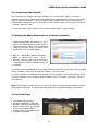
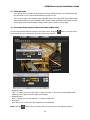
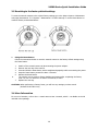
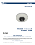
Quick Guide XX271-20-00 V920B Series Bullet Cameras Vicon Industries Inc. Tel: 631-952-2288 Fax: 631-951-2288 Toll Free: 800-645-9116 24-Hour Technical Support: 800-34-VICON (800-348-4266) UK: 44/(0) 1489-566300 Vicon Industries Inc. does not warrant that the functions contained in this equipment will meet your requirements or that the operation will be entirely error free or perform precisely as described in the documentation. This system has not been designed to be used in life-critical situations and must not be used for this purpose. www.vicon-security.com Document Number: 8009-8271-20-00 Product specifications subject to change without notice. Issued: 1114 Copyright © 2014 Vicon Industries Inc. All rights reserved. V920B Series Quick Installation Guide V920B Series Quick Installation Guide 1. Description The information in this manual provides quick installation and setup procedures for the Roughneck® V920B Series of Bullet Cameras. These units should only be installed by a qualified technician using approved materials in conformance with federal, state, and local codes. Read these instructions thoroughly before beginning an installation. Always refer to Vicon’s website to assure you have the most up-to-date manual, www.vicon-security.com. The V920B Series of HD IP cameras is designed for demanding security installations. It offers a number of fixed network camera versions that deliver crisp clear images to fit any installation need. The V920B cameras are fully compatible with all ViconNet® systems; its ONVIF certification provides an open-platform for integration into other video management systems. The housing is designed for easy installation. PoE eliminates the need for power cables, providing a cost-effective method of installation. The V920B features an auto iris lens that adapts to changing outdoor lighting; the true day/night camera includes a removable IR cut filter. 32 IR LED illuminators provide lighting up to 82 ft (25 m). The camera is IP67 rated with that withstands rain. • Installation Steps Follow these steps to install the network camera on your local network (LAN): 1. Check the package contents against the list that follows. 2. Connect the network camera. 3. Set an IP address. 4. Set the password. • Package Component The system comes with the following components: Camera unit Installation CD Installation Quick Guide T emplate Sheet Accessory Kit Optional OSD Controller Check your package to make sure that you received the complete system, including all components shown above. Note: Adapter for12 VDC is not supplied; the optional V920D-OSD OSD Controller can be purchased separately. 3 V920B Series Quick Installation Guide 2. Installation For the network camera to operate, it is necessary to connect a network cable for data transmission and power connection from customer-supplied power supply (if not using PoE). 2.1 Camera Installation Camera Dimensions See the diagrams below for the exact dimensions of the network camera. Unit Dimensions: mm Parts and Description 4 V920B Series Quick Installation Guide Sunshield Installation The unit is shipped without the sunshi eld installed. Use the bolt supplied to secur e the sunshiel d to the body of the camera. Base Installation There are two ways of installing the camera. 3. Route cable through the wall to 1. mounting base. Route cable through the cable knockout tab in mounting base. 1) Installation1 (Cable through the wall with the mount base) PTS1, M5x20 Mounting Screws (3x) Mounting Base Plastic Anchors (3x) Template S heet Wall Loosen the mount screw (M6x16 mm) A. Drill the mounting hole locations, using the template sheet (or the bottom of the mount base) as a guide. B. Insert the supplied plastic anchors into the holes. C. Connect power cable and network line. D. Align the screw holes of the mount base with the plastic anchors. E. Use the mounting screws (M5x20) provided to secure the camera. F. To adjust the camera position, loosen the mount screw (M6x16) to move the camera. Retighten the screw when adjustment is complete. 5 V920B Series Quick Installation Guide 2) Installation 2 (Using the cable knockout tab in mount base) PTS1, M5x20 Mounting Screws (3x) Mounting Base Plastic Anchors (3x) Template S heet Wall Remove the cable knockout tab for cable entry A. Drill the mounting hole locations, using the template sheet (or the bottom of the mount base) as a guide. B. Insert the plastic anchors into the hole which has just drilled. C. Connect connection cable and network lines. D. Fit the screw holes of the mount base into the plastic anchors. E. Remove the cable knockout tab for the cable entry. F. Screw up the mount screws (M5x20). G. To adjust the camera position, loosen the mount screw (M6x16) to move the camera. Retighten the screw when adjustment is complete. 6 V920B Series Quick Installation Guide 2.2 Connections Cable Connections NO Wire Color 1 Red: 12 VDC White: GND 2 Black Description Main Power; 2 pin terminal, 12 VDC 2A (24W) with heater, or 12 VDC 320mA (3.8W) without heater Ethernet; RJ-45 port compatible with 10/100Mbps having PoE functionality. Modular jack. Note: Heater requires 12 VDC. If using PoE, the heater will not operate. • Connecting to the RJ-45 Connect a standard RJ-45 cable to the network port of the network camera. Generally a cross-over cable is used for direct connection to PC, while a direct cable is used for connection to a hub. A router featuring PoE (Power over Ethernet) can be used to supply power to the camera. Micro SD memory slot Remove the rear cap on the camera to insert the SD memory card. • Connecting the Power Connect the power of 12 VDC for the network camera. Connect the positive (+) pole to the ‘+’ position (red) and the negative (-) pole to the ‘-’ position (white) for the DC power. Be careful not to reverse the polarity when connecting the power cable. A router featuring PoE (Power over Ethernet) can be used to supply power to the camera. The heater only operates when using the power source of 12 VDC. If using PoE, the heater will not operate. If PoE and 12 VDC are both applied, the camera will be supplied with power from PoE. 7 V920B Series Quick Installation Guide • Connecting Service Monitor Port Service monitor port is used for easy OSD setup. To make changes from the OSD menu, use the optional OSD controller. ▶ ID & IP assignment To make changes in the OSD menu, the optional OSD controller (V920D-OSD) can be used to set Camera Title and IP Address. 1. 2. 3. 4. Connect the OSD Controller to the Service Monitor port of the network camera. Connect Service Monitor and the Video Output port of the OSD Controller. Press the SET button on the controller to access the Main Menu. Change camera ID and IP address as needed. Additionally, the Name (or title) of the camera can be changed. Use the ↑↓←→ buttons on the controller to change the parameters. 5. Select SAVE or CANCEL to exit the Main Menu. The Video Output can also be used for easy zoom and focus control when adjusting the lens. Video Output is restricted to 704x480 (576) resolution. ▶ Zoom & Focus Control (Models with motorized lens only) The camera enters Zoom and Focus control mode when the OSD Controller is connected to the Service Monitor port. -. Zoom Control: ↑ (Zoom In), ↓ (Zoom Out) -. Focus Control: ← (Focus Near), → (Focus Far) -. Fine Focus: Press and hold the SET button for at least 2 seconds. The camera readjusts focus automatically. Note: The optional V920D-OSD OSD Controller can be purchased separately. 8 V920B Series Quick Installation Guide 2.3 Network Connection and IP assignment The network camera is designed for use on an Ethernet network and requires an IP address for access. Most networks today have a DHCP server that automatically assigns IP addresses to connected devices. By the factory default, your camera is set to obtain the IP address automatically via DHCP server. If your network does not have a DHCP server the network camera will use 192.168.1.100 as the default IP address. If DHCP is enabled and the product cannot be accessed, run the “Smart Manager” utility on the CD to search and allocate an IP address to your products, or reset the product to the factory default settings and then perform the installation again. 1. Connect the network camera to the network and power up. 2. Start SmartManager utility (Start>All Programs>SmartManager>SmartManager); the main window displays. After a short while any network devices connected to the network will be displayed in the list. 3. Select the camera on the list and click right button of the mouse. The pop-up menu below displays. 4. Select Assign IP. The Assign IP window displays. Enter the required IP address. Note: For more information, refer to the Smart Manager User’s Manual. 9 V920B Series Quick Installation Guide 3. Operation The network camera can be used with Windows® operating system and browsers. The recommended browsers are Internet Explorer®, Safari®, Firefox®, Opera® and Google® Chrome® with Windows. Note: To view streaming video in Microsoft® Internet Explorer, set your browser to allow ActiveX controls. Note: Some screens may appear different (i.e., color scheme) depending on the firmware version, but the functionality is the same or similar. 3.1 Access from a Browser 1. Start a browser (i.e., Internet Explorer). 2. Enter the IP address or host name of the network camera in the Location/Address field of the browser. 3. A starting page displays. Click Live View, Playback or Setup to select corresponding web page. 4. Click Live View for the network camera’s Live View page to appear in the browser. 10 V920B Series Quick Installation Guide 3.2. Access from the Internet Once connected, the network camera is accessible on your local network (LAN). To access the network camera from the Internet you must configure your broadband router to allow incoming data traffic to the network camera. To do this, enable the NAT-traversal feature, which will attempt to automatically configure the router to allow access to the network camera. This is enabled from Setup > System > Network > NAT. For more information, refer to section “3.5.5 System>Network>NAT” of User’s Manual. 3.3 Setting the Admin Password over a Secure Connection To gain acc ess t o th e ca mera, the pa ssword for the default administrator user must be set. Thi s is done in the “Admin Password ” dialog, which is displayed wh en the n etwork camera is acce ssed for setup th e first tim e. Enter y our ad min name and password, set by the administrator. Note: The default admi nistrator username is “ADMIN” an d passwor d is “1234” . If the password is lost, the netw ork ca mera mus t be reset t o th e factory default se ttings. See s ection “3.5 Resetting to the Factory Default Settings” for more details. To prevent network eavesdropping when setting the admin password, it can be done via an encrypted HTTPS connection, which requires an HTTPS certificate (see note below). To set the password via a standard HTTP connection, enter it directly in the first dialog shown below. To set the password via an encrypted HTTPS connection, see “3.5.5 System > Security > HTTPS” of User’s Manual. Note: HTTPS (Hypertext Transfer Protocol over SSL) is a protocol used to encrypt the traffic between web browsers and servers. The HTTPS certificate controls the encrypted exchange of information. 3.4 Live View Page The Live View page provides several screen modes (camera model dependant): 2048x1536, 1920x1080, 1280x1024, 1280x720, 704x480 (576), 640x480, 352x240 (288), and 320x240. Select the most suitable mode in accordance with your PC specifications and monitoring purposes. 11 V920B Series Quick Installation Guide 1) General controls Live View Page Search & Playback Page Setup Page Help Page The video drop-down list allows the selection of a customized or preprogrammed video stream on the Live View page. Stream profiles are configured under Setup > Basic Configuration > Video & Image. For more information, see section “3.5.1 Basic Configuration > Video & Image” of this manual. The resolution drop-down list allows the selection of the most suitable video resolutions to be displayed on Live View page. The protocol drop-down list allows the selection of the combination of protocols and methods to use depending on your viewing requirements and on the properties of the network. 2) Control toolbar The live viewer toolbar is available on the web browser page only. It displays the following buttons: video The Stop button stops the video stream being played. Pressing the key again toggles the start and stop. The Start button connects to the network camera or starts playing a stream. The Pause button temporarily stops (pauses) the video stream being played. the The Snapshot button takes a picture (snapshot) of the current image. The location where image is saved can be specified. The Digital Zoom button activates a zoom-in or zoom-out function for the video image on the live screen. scr The Full Screen button causes the video image to fill the entire screen area. No other windows will be visible. Press the 'Esc' button on the computer keyboard to cancel full een view. The Manual Trigger button activates a pop-up window to manually start or stop the event. The Remote Focus button enables users to adjust focus and zoom remotely via network (motorized lens models only). The Fine Focus (one push focus) button readjusts focus automatically to set the focus to the optimum position (motorized lens models only). 12 V920B Series Quick Installation Guide 3) Video Streams The network camera provides several image and video stream formats. Your requirements and the properties of your network will determine the type you use. The Live View page of the network camera provides access to H.264, MPEG-4 and Motion JPEG video streams and to the list of available video streams. Other applications and clients can also access these video streams/images directly, without going via the Live View page. 4) Focus and Zoom Control (Motorized Lens models only) You can control Zoom and Focus from the Live View screen. Press the the Live View screen to activate the Zoom and Focus control panel. button on the left top in • Adjusting Zoom: Click “<” button to zoom out and click “>” button to zoom in. The focus is moved slightly after adjusting zoom; adjust the focus again, as necessary. • Adjusting Focus: Click “>” button for far focus and click “<” button to near focus. • Fine Focus: Click “Fine Focus” to fine tune and readjust focus automatically. Note: Click the button in the Live View screen to set the focus to the optimum position. 13 V920B Series Quick Installation Guide 3.5 Resetting to the factory default settings To reset the network camera to the original factory settings, go to the Setup>System> Maintenance web page (described in “3.5.5 System > Maintenance” of User’s Manual) or use the Reset button on network camera, as described below: • Using the Reset Button Follow the instructions below to reset the network camera to the factory default settings using the Reset button. 1. 2. 3. 4. 5. 6. 7. Switch off the network camera by disconnecting the power adapter. Remove the rear cap of the camera. Press and hold the Reset button with a straightened paperclip while reconnecting the power. Keep the Reset button pressed for about 2 seconds. Release the Reset button. The network camera resets to factory defaults and restarts after completing the factory reset. The unit now obtains the IP address automatically via DHCP. Replace the rear cap. CAUTION: When performing a Factory Reset, you will lose any settings you have saved. (Default IP 192.168.1.100) 3.6 More Information For mor e inf ormation, r efer to the n etwork camer a User ’s manual, which i s av ailable on the CD included in this package. 14 Vicon Industries Inc. Internet Address: www.vicon-security.com V920B 50303846A