
1
PRO ® UZ250
User Manual
A91M.12-705 560.00-0595
PRO ® UZ250
Type: PRO-UZ25
Version 1.0
User Instructions
DOK-705 561.00-0595
Overview
General Remarks
Table of Contents
Part I
How to proceed
Part II
Main Menu PRO ® FWT
Part III
Configuration Instructions
Part IV
KOS 140 - Parameter assignment
Part V
File Structures
Part VI
Index
Part VII
Part VIII
Part IX
00
00
Notes
Table of Contents
00
vii
viii
00
Notes
Application Note
Caution The relevant regulations must be observed for control
applications involving safety requirements.
For reasons of safety and to ensure compliance with documented system data, repairs to components should be performed only by the manufacturer.
Training
AEG Schneider Automation offers suitable training that provides further information concerning the system (see addresses).
Data, Illustrations, Alterations
Data and illustration are not binding. We reserve the right to alter our products in
line with our policy of continuous product development. If you have any suggestions for improvements or amendments or have found errors in this publication,
please notify us by using the form on the last page of this publication.
Addresses
The addresses of our Regional Sales Offices, Training Centers, Service and Engineering Sales Offices in Europe are given at the end of this publication.
00
ix
Copyright
All rights reserved. No part of this document may be reproduced or transmitted
in any form or by any means, electronic or mechanical, including copying, processing or any information storage, without permission in writing by the
AEG Schneider Automation. You are not authorized to translate this document
into any other language.
Trademarks
All terms used in this user manual to denote AEG Schneider Automation
products are trademarks of the AEG Schneider Automation.
ã 1995 AEG Schneider Automation.
x
00
Terminology
Note
This symbol emphasizes very important facts.
Caution This symbol refers to frequently appearing error
sources.
Warning This symbol points to sources of danger that may
cause financial and health damages or may have other aggravating consequences.
Expert This symbol is used when a more detailed information is
given, which is intended exclusively for experts (special training required). Skipping this information does not interfere with understanding the publication and does not restrict standard application of the
product.
Path
This symbol identifies the use of paths in software menus.
Figures are given in the spelling corresponding to international practice and approved by SI (Système International d‘ Unités).
I.e. a space between the thousands and the usage of a decimal point
(e.g.: 12 345.67).
00
xi
Abbreviation
Explanation
A-byte
A1-byte
APS
IL
AWP
BGT
D1-, D2-, D3-, D4-byte
F-byte
GP
IP
SP
KOS
LAN
LM
NLQ
PV-Number
SFB
UST
UZ
Address byte in Modnet 1F
Subaddress byte in Modnet 1F
Automatic Polling Service
Instruction list
User program
Subrack
1st - 4th data byte in Modnet 1F
Function byte in Modnet 1F
General polling
Internal processing
Short polling
KOS 140
Local Area Network
Long message
Near Letter Quality
Process variable number
Standard Function Block
Outstation
Submaster
xii
00
Objectives
This description is intended for configurers of Geadat UZ250 master stations.
The configurer is then able to
install the programming device,
install the software,
configure with the software,
document the configuration,
pass the parameters obtained,
transfer the generated IL to the controller and start it.
Arrangement of This Guide
00
Part I
Check list how to proceed in order to start operations with
a master station.
Part II
Description of the main menu PRO-FWT.
Part III
This part describes how to configure the Geadat UZ250
master station with PRO ® UZ250.
Part IV
This part describes how to parameterize the KOS 140 with
PRO ® UZ250.
Part V
File Structures.
Part VI
contains the index.
xiii
Relevant documentation
Geadat U250
Fernwirktechnik
Benutzerhandbuch
A91M.12-704 132
Automatisierungsgerät A250
Benutzerhandbuch
A91M.12-271 953
Dolog AKF ® A120/A250
Typ AKF125
Version 4.2
Benutzeranleitung
E-Nr. 424 275 181
Validity
This description is valid for the:
Software
PRO ® UZ250, Version 1.0
Dolog AKF ® A120/A250, Version 6.0
KOS 140 firmware
package containing
xiv
FPL 002
FWL 003
FWL 004
FWL 005
FWL 006
FWL 051
FWL 052
703
700
700
700
700
700
700
558.00
171.00
173.00
174.00
175.00
178.00
179.00
00
Handling 3 1/2” Diskettes
No cleaning of diskettes.
Store diskettes in protective
containers and boxes.
Temperature 10 to 60 C
Humidity
8 to 80%
No water on diskettes.
Insert diskettes correctly.
No erasing on diskettes.
Don’t move the metal slide.
No heavy objects on diskettes.
Diskettes tolerate no heat
(sunshine).
Label diskettes at the
right spot.
No diskettes near magnetic fields.
No forcing diskettes into
disk drive.
Always keep in mind
20
xv
Handling 5 1/4” Diskettes
No diskettes near magnetic fields.
No cleaning of diskettes.
Insert diskettes correctly.
No erasing on diskettes.
Touch only protected parts
of diskettes.
Store diskettes in protective
containers and boxes.
No bending or folding of
diskettes.
Label diskettes at the
right spot.
Temperature 10 to 50 C
Humidity
8 to 80%
No water on diskettes.
No heavy objects on diskettes.
Diskettes tolerate no heat
(sunshine).
No painted pencils for
writing on diskettes.
No paper clips on diskettes.
No forcing diskettes into
disk drive.
Always keep in mind
xvi
20
Table of Contents
Part I
Chapter 1
1.1
1.2
1.3
Part II
Chapter 1
1.1
1.2
1.3
1.3.1
1.3.2
1.4
1.5
Part III
00
How to proceed . . . . . . . . . . . . . . . . . . . . . . . . . 1
Check List . . . . . . . . . . . . . . . . . . . . . . . . . . . . . . . . . . . . . . .
Checklist for parameterizing and configuring . . . . . . . . . .
Checklist for system startup . . . . . . . . . . . . . . . . . . . . . . . .
Checklist for parametrization and programming . . . . . . .
3
4
6
7
Main Menu PRO ® FWT . . . . . . . . . . . . . . . . . 9
Operating . . . . . . . . . . . . . . . . . . . . . . . . . . . . . . . . . . . . . . .
General Information . . . . . . . . . . . . . . . . . . . . . . . . . . . . . .
Expert system PRO... . . . . . . . . . . . . . . . . . . . . . . . . . . . . .
Dolog AKF... . . . . . . . . . . . . . . . . . . . . . . . . . . . . . . . . . . . . .
...Read in ASCII . . . . . . . . . . . . . . . . . . . . . . . . . . . . . . . . . .
...Call . . . . . . . . . . . . . . . . . . . . . . . . . . . . . . . . . . . . . . . . . . .
Tools . . . . . . . . . . . . . . . . . . . . . . . . . . . . . . . . . . . . . . . . . . .
Desktop . . . . . . . . . . . . . . . . . . . . . . . . . . . . . . . . . . . . . . . . .
11
12
14
15
15
16
17
18
Configuration Instructions . . . . . . . . . . . . . . 21
Chapter 1
1.1
1.2
1.2.1
1.2.2
1.3
Introduction . . . . . . . . . . . . . . . . . . . . . . . . . . . . . . . . . . . . .
Program package PRO ® UZ250 . . . . . . . . . . . . . . . . . .
System requirements . . . . . . . . . . . . . . . . . . . . . . . . . . . . .
Hardware . . . . . . . . . . . . . . . . . . . . . . . . . . . . . . . . . . . . . . . .
Software . . . . . . . . . . . . . . . . . . . . . . . . . . . . . . . . . . . . . . . .
Installation . . . . . . . . . . . . . . . . . . . . . . . . . . . . . . . . . . . . . . .
23
24
25
26
26
26
Chapter 2
2.1
2.2
2.3
2.4
2.5
Overview And General Information . . . . . . . . . . . . . . .
Summary of Features . . . . . . . . . . . . . . . . . . . . . . . . . . . . .
Rough structure . . . . . . . . . . . . . . . . . . . . . . . . . . . . . . . . . .
Keyboard operation . . . . . . . . . . . . . . . . . . . . . . . . . . . . . . .
Mouse operation . . . . . . . . . . . . . . . . . . . . . . . . . . . . . . . . .
General information . . . . . . . . . . . . . . . . . . . . . . . . . . . . . . .
27
28
29
30
32
33
Table of Contents
xvii
Chapter 3
3.1
3.2
3.3
Overview How To Work . . . . . . . . . . . . . . . . . . . . . . . . . .
Flow Chart . . . . . . . . . . . . . . . . . . . . . . . . . . . . . . . . . . . . . .
Tree Structure of the Menues . . . . . . . . . . . . . . . . . . . . . .
Directory Structure . . . . . . . . . . . . . . . . . . . . . . . . . . . . . . .
35
36
37
40
Chapter 4
4.1
4.1.1
4.1.2
4.1.3
4.1.4
4.1.5
4.2
4.3
4.4
4.5
4.6
4.7
4.8
Configuration . . . . . . . . . . . . . . . . . . . . . . . . . . . . . . . . . . .
Definition of the Interfaces . . . . . . . . . . . . . . . . . . . . . . . . .
KOS Data Structure . . . . . . . . . . . . . . . . . . . . . . . . . . . . . .
Structure of the Transfer Blocks . . . . . . . . . . . . . . . . . . . .
Allocation Switch . . . . . . . . . . . . . . . . . . . . . . . . . . . . . . . . .
Internal Interface . . . . . . . . . . . . . . . . . . . . . . . . . . . . . . . . .
Internal Data Model . . . . . . . . . . . . . . . . . . . . . . . . . . . . . . .
Definition of the Types of Linkage . . . . . . . . . . . . . . . . . .
System Information . . . . . . . . . . . . . . . . . . . . . . . . . . . . . . .
Configuration Limits . . . . . . . . . . . . . . . . . . . . . . . . . . . . . .
Special Features . . . . . . . . . . . . . . . . . . . . . . . . . . . . . . . . .
System Information . . . . . . . . . . . . . . . . . . . . . . . . . . . . . . .
System Commands . . . . . . . . . . . . . . . . . . . . . . . . . . . . . . .
Messages for Master APS Operation . . . . . . . . . . . . . . .
43
44
44
45
48
49
50
52
53
54
55
57
58
59
Chapter 5
5.1
5.1.1
5.1.2
5.1.3
5.2
5.2.1
5.2.2
5.2.3
5.2.4
5.2.5
5.2.6
5.3
5.4
5.5
5.6
5.7
Handling . . . . . . . . . . . . . . . . . . . . . . . . . . . . . . . . . . . . . . . . 61
General Information . . . . . . . . . . . . . . . . . . . . . . . . . . . . . . 62
The Line Editor . . . . . . . . . . . . . . . . . . . . . . . . . . . . . . . . . . 63
Starting PRO ® UZ250 E1 B1 . . . . . . . . . . . . . . . . . . . . . 64
Autosave . . . . . . . . . . . . . . . . . . . . . . . . . . . . . . . . . . . . . . . . 65
Data Input E2 B1 . . . . . . . . . . . . . . . . . . . . . . . . . . . . . . . . . 66
Project data E3 B1 . . . . . . . . . . . . . . . . . . . . . . . . . . . . . . . 66
Submaster Configuration E3 B2 . . . . . . . . . . . . . . . . . . . . 68
Line Configuration E3 B3 . . . . . . . . . . . . . . . . . . . . . . . . . . 72
Selection of Subracks E2 B1 . . . . . . . . . . . . . . . . . . . . . . 78
Selection of Modules E2 B1 . . . . . . . . . . . . . . . . . . . . . . . 79
Edit Library E3 B8 . . . . . . . . . . . . . . . . . . . . . . . . . . . . . . . . 83
Data Archive E1 B1 . . . . . . . . . . . . . . . . . . . . . . . . . . . . . . 85
Generate ASCII Import Files for AKF E1 B1 . . . . . . . . . 87
Printer Output E1 B1 . . . . . . . . . . . . . . . . . . . . . . . . . . . . . . 92
Display on the Screen E1 B1 . . . . . . . . . . . . . . . . . . . . . . 99
Bottom-Up Configuration Import E1B1 . . . . . . . . . . . . . 101
xviii Table of Contents
00
Chapter 6
6.1
6.2
6.3
6.4
SFB 394
SFB 395
SFB 396
SFB 397
SFB 398
SFB 399
SFB 400
SFB 401
SFB 402
6.5
6.5.1
6.5.2
6.6
Part IV
00
IL-Blocks and Macros . . . . . . . . . . . . . . . . . . . . . . . . . .
Overview . . . . . . . . . . . . . . . . . . . . . . . . . . . . . . . . . . . . . . .
List of the AKF blocks used . . . . . . . . . . . . . . . . . . . . . .
List of the Markers Used under AKF . . . . . . . . . . . . . . .
Standard Function Blocks in Telecontrol Engineering
UZ_UTMF Convert Message to Marker Word . . . . . . .
UZ_UMTF Convert Marker Word to Message . . . . . . .
UZ_AEND Recognize Change Bit . . . . . . . . . . . . . . . . .
UZ_AZI AZI-Calculation . . . . . . . . . . . . . . . . . . . . . . . . . .
UZ_SCHW Monitor Pulse Threshold . . . . . . . . . . . . . . .
UZ_ANV Old/New Comparison for Signals . . . . . . . . . .
UZ_V250 Message Distribution in UZ250 . . . . . . . . . . .
U_KOSSTA KOS140/141 Read Status Field . . . . . . . .
U_DEZSTA DEZ161 Read Status Field . . . . . . . . . . . .
Internal Data Model UZ250 . . . . . . . . . . . . . . . . . . . . . . .
Converting Organization Signals . . . . . . . . . . . . . . . . . .
Transfer Blocks for Data from the Internal
Processing . . . . . . . . . . . . . . . . . . . . . . . . . . . . . . . . . . . . .
Symbolic Addressing in the UZ250 . . . . . . . . . . . . . . . .
103
104
104
106
107
108
110
112
114
117
119
121
125
127
129
130
132
134
KOS 201 - Parameter assignment . . . . . . 137
Chapter 1
1.1
1.2
1.2.1
1.2.2
1.2.3
Handling . . . . . . . . . . . . . . . . . . . . . . . . . . . . . . . . . . . . . . .
Structure of KOS Menues . . . . . . . . . . . . . . . . . . . . . . . .
Special Features . . . . . . . . . . . . . . . . . . . . . . . . . . . . . . . .
Autosave . . . . . . . . . . . . . . . . . . . . . . . . . . . . . . . . . . . . . . .
KOS Parameter List . . . . . . . . . . . . . . . . . . . . . . . . . . . . .
Read in Parameter EPROM . . . . . . . . . . . . . . . . . . . . . .
139
140
141
141
141
142
Chapter 2
2.1
2.2
2.2.1
2.2.2
2.2.3
2.2.4
2.2.5
2.3
2.4
2.5
Operating . . . . . . . . . . . . . . . . . . . . . . . . . . . . . . . . . . . . . .
KOS main menu E4 B5 . . . . . . . . . . . . . . . . . . . . . . . . . .
Data entry E5 B1 . . . . . . . . . . . . . . . . . . . . . . . . . . . . . . . .
SEAB parameter E6 B1 . . . . . . . . . . . . . . . . . . . . . . . . . .
APS Parameter E6 B2 . . . . . . . . . . . . . . . . . . . . . . . . . . .
KOS Parameters E6 B3 . . . . . . . . . . . . . . . . . . . . . . . . . .
Data Monitoring Direction E6 B4 . . . . . . . . . . . . . . . . . .
Set Transfer Bit E6 B5 . . . . . . . . . . . . . . . . . . . . . . . . . . .
Transfer E5 B2 . . . . . . . . . . . . . . . . . . . . . . . . . . . . . . . . . .
EPROM Menu . . . . . . . . . . . . . . . . . . . . . . . . . . . . . . . . . .
Display Conversion Lists E5 B4 . . . . . . . . . . . . . . . . . . .
143
144
145
145
146
152
155
156
157
159
162
Table of Contents
xix
Part V
Chapter 1
1.1
1.2
1.2.1
1.2.2
1.2.3
1.3
1.4
Part VI
File Structures . . . . . . . . . . . . . . . . . . . . . . . 163
File Structures . . . . . . . . . . . . . . . . . . . . . . . . . . . . . . . . .
Bottom-Up File . . . . . . . . . . . . . . . . . . . . . . . . . . . . . . . . . .
Strukturen . . . . . . . . . . . . . . . . . . . . . . . . . . . . . . . . . . . . . .
Structure of file header . . . . . . . . . . . . . . . . . . . . . . . . . . .
Structure of Communications File . . . . . . . . . . . . . . . . .
Structure of PV Number List: . . . . . . . . . . . . . . . . . . . . .
List of the PV attributes: . . . . . . . . . . . . . . . . . . . . . . . . . .
Example File Z020-001.KOM . . . . . . . . . . . . . . . . . . . . .
165
166
167
167
167
168
169
170
Index . . . . . . . . . . . . . . . . . . . . . . . . . . . . . . . . 173
Index . . . . . . . . . . . . . . . . . . . . . . . . . . . . . . . . . . . . . . . . . . 175
xx
Table of Contents
00
Part I
How to proceed
00
1
2
00
Chapter 1
Check List
Step by step procedures for
configuration
parameterizing and programming
system start-up
of a Geadat UZ250 outstation are defined here using check lists.
00
Check List
3
1.1
Checklist for parameterizing and
configuring
Before you start the configuration of your UZ250 master station with the software
package PRO ® UZ250, you should read the following checklist and refer to the
corresponding chapters for details.
Make sure that you have the right software environment for the configuration
software PRO ® UZ250 (Part III, chapter 1.2)
Make sure that you have the right hardware environment (Part III, chapter 1.2)
Install the configuration software PRO ® UZ250
Learn how to use the keyboard and the mouse (Part III, chapter 2.3 and 2.4)
Start the configuration aid PRO - UZ250 via the main menu PRO ® FWT
(Part II, chapter 1.3 and Part III, chapter 5.1.2)
Go to the data entry level (Part III, chapter 5.2)
Enter the system name and the master station address via the “configuration
data” menu (Part III, chapter 5.2.1)
Enter the submaster configuration (Part III, chapter 5.2.2)
Activate the “Line-configuration” menu and enter the outstation list and the input/output data (Part III, chapter 5.2.3)
Activate the “module selection” menu and enter the changes and additions, if
necessary.
Call the KOS parametrization using the ZOOM function in the menu ”Module
selection”. Begin with the master KOS (Part III, chapter 5.2.5).
4
Check List
00
Define the message distribution for the master KOS in the menu ”Data for
monitoring direction” (Part IV, chapter 2.2.4).
Check whether the settings correspond to your requirements for signal
prompting (Part IV, chapter 2.2.5) for the slave KOS in conversion mode.
Check whether the SEAB parameters and APS parameters are correctly set
for your requirements (Part IV, chapters 2.2.1 and 2.2.2).
Check whether the KOS parameters are correctly set for your requirements.
Enter the station address for a slave KOS (Part IV, chapter 2.2.3).
Generate the KOS firmware EPROMs
If necessary, now generate the parameter EPROMs
Leave the KOS parametrization and return to the PRO ® UZ250 main menu.
Call the menu ”Generate ASCII import files for AKF” (Part III, chapter 5.4)
If ”Internal Processing” was chosen in the submaster configuration menu, also
call ”Internal Processing” first (Part III, chap. 5.2.2)
Activate the IL generation (Part III, chapter 5.4)
Generate the ASCII import files
Save your system to disk (Part III, chapter 5.3)
Print the documentation (Part III, chapter 5.6)
00
Check List
5
1.2
Checklist for system startup
Verify that the switches and jumpers of each module are set correctly.
Plug the firmware Eproms into the KOS.
If necessary, mount the UEM 001 on the KOS.
Mount the subracks.
Plug and wire the boards into the slots defined in the configuration.
6
Check List
00
1.3
Checklist for parametrization and programming
Once you have completed the configuration and start-up of the hardware, you
can proceed with the parametrization of the KOS and the programming and the
PC*.
Caution If it is the initial start-up, the ALU basic software must
first be booted.
Leave the expert software PRO-UZ250
Call the function ”Read in ASCII” for AKF125 in the PRO-FWT main menu
(Part II, chap. 1.3.1)
Then call the function ”AKF25 call” (Part II, chap. 1.3.2)
Create the link to the PC* with the ”Setup” menu
Choose the ”Load” menu
Link the program
Load the program
or
Generate a PC* EPROM
Load the expert data for KOS one after the other
Start the PC* with the ”Online” menu
Note Further information about start-up can be found in the user
manuals Geadat 250 and Modicon A250.
00
Check List
7
8
Check List
00
Part II
Main Menu PRO ® FWT
00
9
10
00
Chapter 1
Operating
00
Operating
11
1.1
General Information
The PRO-FWT main menu enables you to choose individual software packages
required for starting up a Geadat telecontrol station without having to return to
the DOS level.
Note Of course only the software packages which were installed
can be called.
Note This main menu is always installed with the individual software
packages PRO... It is started from the operating system level with
the call “PRO-FWT”.
12
Operating
00
Operation:
You can select one of two kinds of operator interface.
Pulldown menues
Icons
The interface can be set with the >Desktop<.
Both interfaces can be used with the cursor keys and with the mouse.
The individual menues or functions are called by clicking with the left mouse key
or with RETURN. In pulldown menus, the call can also be made using the reference characters, which are displayed in a different color.
The menu window is closed with ESC or by clicking with the right mouse key.
Passive functions are displayed in the pulldown menu without a reference charcter and in a different color. These cannot be selected or are skipped with the
cursor.
Example: The program is in graphic mode; only a switch to text mode is now
possible. After switching, the graphic mode function is active and the text mode
function is passive.
00
Operating
13
1.2
Expert system PRO...
The 120-series includes the expert systems:
PRO-U120
for outstations with Modnet 1/F
PRO-UZ250
for submaster stations with Modnet 1/F
PRO-Z120
for master stations with Modnet 1/F
PRO-U121
for outstations with Modnet 1/W
PRO-M121
for mimic diagram control with Modnet 1/W (in preparation)
The 250-series contains the expert systems:
PRO-U250
for outstations with Modnet 1/F
PRO-UZ250
for submaster stations with Modnet 1/F
PRO-UZ251 for submasters with Modnet 1/W (in preparation)
14
Operating
00
1.3
Dolog AKF...
The two software products AKF12 and AKF25 are provided for programming the
telecontrol stations.
The 120-series can be programmed with AKF12. The 250-series can be programmed with AKF25.
Note The Dolog AKF... software has large memory requirements. If
you loaded memory-resident programs or operator interfaces, the remaining main memory may not be sufficient for Dolog AKF. In this case the functions “Read in ASCII-IL” and “Call” cannot be executed.
Leave PRO-FWT and remove the call of these programs from the
“AUTOEXEC.BAT” or the “CONFIG.SYS” and make a warm restart
(<Ctrl>+<Alt>+<Del>). Then start PRO-FWT and select “Read in
ASCII-IL” or “Call” again.
1.3.1
...Read in ASCII
With this call, the particular AKF reads in a control file generated by PRO-Tool
(AKF12.CMD or AKF25.CMD).
The AKF station is set up using this control file and the ASCII-IL generated by
PRO-Tool is read in.
The station which was last processed with a PRO-Tool by the function “Set up
PLC Station” or “Generate ASCII Import Files for AKF” is always processed.
00
Operating
15
1.3.2
...Call
Dolog AKF can be started directly by PRO-FWT with this call.
All the Dolog AKF functions can be executed.
If you only use the standard IL of PRO... and have no special IL blocks, you can
limit yourself to the following function calls:
Set up link to PLC
Bootload basic software
Link IL
Load IL in the RAM and start
or
Program IL on EPROM
Print IL
The exact instructions can be found in the Dolog AKF A120/A250 user manual.
Caution The PRO-Tools assume Dolog AKF A120 version 5.0
bzw. Dolog AKF ® A120/A250 Version 4.2 voraus.
16
Operating
00
1.4
Tools
The following 3 tools can be used together with special PC plug-in cards to simulate master stations and outstations.
Teleview:
For Modnet 1/F/1N together with PC-V24, PC-GDUE, PC-WT
TEL001
For Modnet 1/F/1N and AWD together with PC-AWD1
TEL002
For Modnet 1/W together with PC-AWD1
PRO-SFB
This tool copies the SFBs developed specially for telecontrol engineering into the
AKF125 directory and creates a file SFB.BAT, which links these SFBs into
AKF125.
The function must be called once after each installation of AKF125 or PROUZ250. The sources for the SFBs are installed together with the PRO-SFB program using PRO-UZ250.
00
Operating
17
1.5
Desktop
Language
You can switch directly between German and English.
Screen
PRO-FWT can run as required in graphic mode or in text mode with an EGA or
VGA card. For all other screen adaptors, there is an automatic switch to text mode and this setting cannot be changed.
In graphic mode you can also define whether PRO-FWT should work with icons
or only with pulldown menues.
You can choose one of three color representations both in graphic and in text
mode. For clarity you should choose two-tone representation for some PCs. The
pulldown menues have a light background for “black-and-white”, and a dark
background for “inverse black-and-white”.
Version numbers
The current data (part number, version, date) are entered in a version file when
the individual PRO-tools are installed. The file is displayed on the screen with
this function.
The display is in a scroll box, i.e. it can be shifted up/down with the cursor or by
clicking the cursor fields with the mouse cursor.
18
Operating
00
AKF Program Path
In order to be able to work with different AKF versions, the program path of the
required AKF12 and AKF23 version can be entered here. PRO--FWT provides
the default settings of the AKF installation program as default entries. The subdirectory in which the AKF12.EXE or AKF25.EXE reside including the drive identifier must be defined as program path.
Example: C:\AEG--A91\AKF125
C:\AEG--A91\AKF25V5
D:\AKF125
You must make sure that a ”\” is entered after the drive identifier to specify the
program path from the master directory. The current entries are stored when you
leave PRO--FWT and are available again at the next call.
PRO--FWT always works with the current program paths in the calls ”Read in IL”
and ”AKF..call”.
00
Operating
19
20
Operating
00
Part III
Configuration Instructions
00
21
22
00
Chapter 1
Introduction
00
Introduction
23
1.1
Program package PRO
®
UZ250
The program package PRO-UZ250 consists of
disks with the configuration software
a disk with the KOS firmware
the user manual
24
Introduction
00
1.2
System requirements
Hardware
UZ250
Software
ALU 151
EPROM
Firmware
KOS
DEZ
SPS
KOS 140
EPS 2000
YDL 52
YDL 36.1
YDL 44
Operating system
MS-DOS
PUTE
IBM-kompatible
YDL 32
PRO
UZ250
Dolog AKF
A120/A250
KOS - Firmware
DEZ - Frimware
Printer
Figure 1 Components for configuration and programming
00
Introduction
25
1.2.1
Hardware
PUTE
Printer
IBM-compatible PCs with hard disk and 640 Kbyte main
memory. A guarantee is only given for
AEG Schneider Automation devices.
(with parallel interface)
DRU 292/293
DRU 120
DRU 096
DRU 1200
PRT 294/295
EPROM programming station
EPS 2000
1.2.2
Software
DOS Version 5.0, 6.0, 6.1
Dolog AKF ® A120/A250 Version 4.2
1.3
Installation
Installation PRO ® UZ250
Switch on device (operating system level), display “C>”.
26
Step 1
Diskette 1 in diskette drive A or B
Step 2
Installation routine with call ”A:INSTAL” or ”B:INSTAL”, depending on the drive selected, and start <Cr>.
Step 3
Now follow the directions given in the installation routine.
Introduction
00
Chapter 2
Overview And General
Information
00
Overview And General Information
27
2.1
Summary of Features
PRO ® UZ250 supports the user in the configuration and start-up of the Geadat
UZ250 master station.
The subracks including module assignment are defined automatically by specifying the lines to the outstations (Master KOS) and master stations (slave
KOS).
A bill of materials is determined for the configured station.
An instruction list (IL) is generated based on the parameters entered
Symbol tables and external data structures for the ”Internal Processing” are
generated.
Transfer of instruction list to Dolog AKF ® A120
The expert station is generated for parametrizing the KOS with AKF125
Transfer of generated parameters to KOS 140 with EPROM.
System documentation by printing
the bill of materials
hardware configuration
submaster configuration
loading
KOS data
Internal processing
Archiving on hard disk or diskette of the files entered and generated
A bottom-up configuration with PRO-U250 and PRO-U120 is possible
28
Overview And General Information
00
2.2
Rough structure
Data entry (Chapter 5.2)
Project data
Submaster configuration
Line configuration
Subrack selection
Module selection
Library
Archiving (Chap. 5.3)
Read Data
Save Data
Erase File
Change Drive
Generate ASCII import files for AKF (Chap. 5.4)
Generate ASCII--IL (German)
Generate ASCII--IL (English)
Create ASCII import files
Internal processing
Printer output (Chap. 5.5)
Print the bill of materials
Print the hardware configuration
Print the submaster configuration
Print the loading
Print the internal processing
Print the KOS data
Print all lists
Printer selection
Printer output to file
00
Overview And General Information
29
Screen Output (Chap. 5.6)
Display the System configuration
Display the bill of materials
Bottom--up configuration import (Part V, Chap. 1)
Black--and--white / color switch
Return to PRO--FWT main menu
Language selection German/English
2.3
Keyboard operation
If a command is specified in pointed brackets < > in the following description,
this means that the corresponding key should be pressed.
<Cr> = Press RETURN key.
<Alt>+<Ctrl>+<Del>=Warm restart, all three keys are pressed simultaneously.
<F1> ® <F3> = the function keys F1 and F3 are pressed one after the other.
US keyboard
German keyboard
<Esc>
<Ctrl>
<Home>
<End>
<Prtsc>
<PgUp>
<PgDn>
<Ins>
<Del>
<Return>
<Eing lösch>
<Strg>
<Pos1>
<Ende>
<Druck>
<Figure >
<Figure ¯ >
<Einf>
<Entf> oder <Lösch>
<Übernahme> (auch <Enter> oder <¿ >)
30
Overview And General Information
00
Function keys
The individual submenues are selected with the function keys.
There is always a return to the previous menu level with <F9>.
Help is always called with <F10>.
Arrow keys (cursor keys)
The parameters are selected or modified in some menues with these keys.
Caution If your PUTE does not have a separate cursor block,
make sure that the key <Num Lock> is switched off as otherwise
the number block is active.
<Return> key
The input in the line editor is terminated or the selected parameter is accepted
with this key.
<Esc> key
There is a return to the previous menu level with this key.
Toggle
Different settings can be selected by pressing the <Return> key repeatedly.
00
Overview And General Information
31
2.4
Mouse operation
The right mouse key corresponds to <Esc> or <F9>.
Menu call:
Set the mouse cursor to the red (inverse) function key fields and click with the
left key.
Selection within the menu:
Set the mouse cursor to the desired input line or selection field and click with the
left mouse key.
Set the module or slot location in the menu ”I/O-module selection” in this way
and then delete or set by clicking the red (inverse) function fields.
A selected module can also be entered by twice clicking a subrack location.
File selection window:
Select the system or file with the mouse cursor and click with the left mouse key.
If the mouse cursor is set to the upper or lower free line in the window and
clicked, the scroll function is carried out if necessary.
Setting the mouse cursor to the text RETURN and clicking activates the corresponding RETURN function.
32
Overview And General Information
00
2.5
General information
The following symbol specifies how to select the described function.
Counting always starts with the main menu.
The brackets contain the function keys which must be pressed in the
main menu.
Example:
“Data input”,”Subrack selection”
(F1 ® F4)
Note The specifications Ex By in the titles are also included in the
lower right corner of the screen pages. They display the menu level
and menu image.
In this way the relevant chapter for a particular screen page can easily be found using a cross reference list.
Remark window:
If an incorrect input is made when configuring with PRO ® UZ250 or if a limit is
exceeded, this is displayed on the screen with the corresponding output. In order
to delete this remark window from the screen, press any key. You can then correct the input and continue with configuration.
YES--NO Box
In a YES--NO box, only <Y> or <N> may be entered or the corresponding field
can be clicked with the mouse cursor. Some of the functions can be aborted with
<Esc> if entry is not compulsory for the system.
00
Overview And General Information
33
34
Overview And General Information
00
Chapter 3
Overview How To Work
00
Overview How To Work
35
3.1
Flow Chart
Start
Archive station
Data input
Project data
Name of system
an No. of master
have to be input
Document station
Read ASCII-IL
in Dolog AKF
Submaster configuration
Call Dolog AKF,
link IL
Line configuration
Subrack selection
Program EPROM
Module selection
Insert EPROM’s on KOS and
ALU. Set jumpers on all
modules. Insert modules
in subrack.
KOS-Parametrization
For master KOS
enter data range.
Set SEAB parameters
Program EPROMs
1)
End
Return to PRO-UZ250
main menu and generate
ASCII import files for AKF
Internal processing
1)
Generation of IL
Create ASCII import files
1) If necessary
36
Overview How To Work
00
3.2
Tree Structure of the Menues
Level 1
Level 2
Figure 1
Project data
Submaster config.
Line configuration
Subrack selection
Module selection
Library
Figure 1
Data input
Data archive
ASCII-Importdateien
für AKF erzeugen
Printer output
Display on screen
Bottom-UpConfiguration
Import
F1
F2
F3
F4
F5
F1/B1
F2/B2
F3/B3
F4/B4
F5/B5
F6/B6
Figure 2
Read data
Save data
Erase data
Change drive
Figure 3
IL-Generation DE
IL-Generation EN
Create ASCII
import files
Switch
monochrom/color
Return to
PRO-FWT Main menu
Internal processing
Language selection
German/English
Printer Output (F1-F7)
Printer Selection
Printer Output
to File
F4/B7
Figure 4
Figure 5
F1/B8
Display system
configuration
F2/B9
Display bill of material
00
Overview How To Work
37
Level 3
Level 4
Figure 1
F1/B1
Input
F2/B2
Figure 2
Input
B1
B2
Figure 3
Outstation list
Monitoring Direction
Outstation list
Control Direction
F3/B3
Data Monitoring
Direction
Data Control
Direction
Internal processing
monitoring direction
Internal processing
control direction
F4/B4
F5/B5
B1
B2
B3
B4
Selection
B6
Edit library
Copy library
Delete library
Figure 7
F4/B7
B7
Figure 8
Display
F2/B9
Figure 9
Display
38
B8
Overview How To Work
B6
Figure 2
Input
Figure 3
Input
Figure 4
Input
Figure 5
Input
Figure 6
Input
B7 Data input
Transfer
EPROM menu
Display
conversion list
Bottom-Up-Config.
Export
F1/B1
F1/B2
F1/B3
F2/B4
F3/B5
F4/B6
Figure 8
B8
B9
B10
Marker offsets for data to IP
Marker offsets for data from IP
Generate ”data to IP” list
B11
Generate ”data from IP” list
Marker offsets for LAN and IP
F1/B8
B5
Input
Figure 7
Figure 6
F6/B6
B4
B5
Figure 4
Selection
Figure 5
B3
Figure 1
B9
B10
B11
Selection
Figure 9
Input
Figure 10
Input
Figure 11
Input
00
Level 5
Level 6
Figure 1
F1/B1
Allocation Switch
Figure 2
F1/B2
F1/B3
Edit A1-Byte
Figure 3
SEAB parameter
AWD
KOS parameter
Set Transfer Bit
Figure 1
F1
F1
F2
F3
Input
Figure 2
Input
Figure 4
F2/B4
Figure 3
Generate AKF station
Read in AKF station
Input
Figure 5
Figure 5
F3/B5
Figure 6
F4/B6
00
Input
Read Param. EPROM
Program Param. EPROM
Read firmware
EPROM
Program firmware
EPROM
Read firmware file
EPROM Blank Check
Monitoring Direction
Commands
SEt Point Value
Figure 6
Display
Figure 7
F1
F2
F3
Display
Figure 8
Display
Overview How To Work
39
3.3
Directory Structure
During installation, the TOOL directory PRO-UZ250 is set up in the main directory PRO-FWT. The individual programs (EXE files) and the system information for
PRO-UZ250 are stored there. The subdirectory TEXTE is also set up there.
TEXTE contains the macros for generating the IL, the files with the menu and
help texts, the library and the firmware file for KOS 140.
The files set up by PRO-UZ250 are stored as follows:
C:\Anlage.PRO
FW
Z000-002.KFL
_SEND
Expert
_RCV
KOS
KOS_S
KOS_R
Z000-000.HW
Z000-000.EST
Z000-000.TOP
Z000-001.KOM
Z000-001.KOS
Z000-008.INI
40
Z000.ABL
<- for ASCII import
Z000.AWL
<- for Dolog AKF
Z000.ASD
<-
Z000.AST
<-
LSTA1.EDB
<-
LSTB1.EDB
<-
LSTC1.EDB
<-
Overview How To Work
00
Explanations about Zxxx-yyy.HW etc.
xxx
yyy
Master station no.
(001 ... 127)
Line number
(001 ... 999) or
Teilnehmernummer KOS
or
The number 000 is used for files which contain the data for
the whole master station and which are not assigned to a certain line.
The name for the plant directory and the submaster numbers are entered in the
”Project Data” menu (see Part II, chap. 5.2.1). The line numbers are entered in
the ”Submaster Configuraiton” submenu.
The node numbers of the KOS and not the line numbers are used for distinguishing in the remote load station of the KOS. This should make it easier for
the user to enter data to the menu ”Load Expert Data” under Dolog AKF.
00
Overview How To Work
41
42
Overview How To Work
00
Chapter 4
Configuration
00
Configuration
43
4.1
Definition of the Interfaces
4.1.1
KOS Data Structure
The KOS data structure contains 180 bytes in each direction.
Since the ALU and the KOS run asynchronously, a handshake is installed with
the transfer status (1st byte in the data structure). This ensures that no data
which was not yet processed by the other end is overwritten.
Once all the bytes to be transferred have been set, a ”1” is entered in the transfer status byte. No new data may be transferred as long as the other end has
not acknowledged the old data with ”0”.
The input and output bytes are set as follows:
USTE x.y
USTA x.y
Input direction (KOS to ALU)
Output direction (ALU to KOS)
USTE x.1
USTA x.1
Transfer status (input direction)
Transfer status (output direction)
USTE x.2
USTA x.2
Number of data blocks (8)
Number of data blocks (8)
USTE x.3
USTA x.3
Reserve
Reserve
From USTE x.4
From USTA x.4
44
Transfer blocks input direction
Transfer blocks output direction
Configuration
00
4.1.2
A
Structure of the Transfer Blocks
P
P
A - byte
F - byte
T
T
T
A =
P =
T =
Task bit
Log 01 ! Modnet 1/F
Message typ 000 ! ALU to KOS
010 ! ALU to KOS*
A1 - byte
D4 - byte
D3 - byte
D2 - byte
D1 - byte
* only for master APS
Figure 2 Output direction (starting with USTA x.4)
The task byte is set to 88H if the transfer block contains a message.
00
Configuration
45
Transfer field for data in the command direction (10 bytes)
A
P
P
T
T
Allocation Switch list L
Allocation Switch List H
T
A =
P =
T =
task bit
log 01 ! Modnet 1/F
message type 100 ! KOS to ALU
110 ! KOS to ALU*
A - byte
F - byte
A1 - byte
D4 - byte
D3 - byte
D2 - byte
D1 - byte
* only for master AWD
Figure 3 Input direction (starting with USTE x.4)
The task byte is set to 8CH by the KOS-FW.
46
Configuration
00
Table 1 Distribution of the Blocks in the USTA and USTE Fields
USTA
USTA
USTA
USTA
USTA
USTA
USTA
USTA
x.
x.
x.
x.
x.
x.
x.
x.
4
12
20
28
36
44
52
60
...
...
...
...
...
...
...
...
USTA
USTA
USTA
USTA
USTA
USTA
USTA
USTA
x.
x.
x.
x.
x.
x.
x.
x.
11
19
27
35
43
51
59
67
1st block
2nd block
3rd block
4th block
5th block
6th block
7th block
8th block
USTE
USTE
USTE
USTE
USTE
USTE
USTE
USTE
x.
x.
x.
x.
x.
x.
x.
x.
4
14
24
34
44
54.
64
74
...
...
...
...
...
..
USTE
USTE
USTE
USTE
USTE
USTE
USTE
USTE
x.
x.
x.
x.
x.
x.
x.
x.
13
23
33
43
53
63
73
83
1st block
2nd block
3rd block
4th block
5th block
6th block
7th block
8th block
Transferring the time to the ALU
KOS stores the current time in the last 8 bytes USTE x.173 ... USTE x.180 in
each transfer scan.
USTE
USTE
USTE
USTE
x.173
x.175
x.177
x.179
=
=
=
=
year
day of the week
hour
special character
USTE
USTE
USTE
USTE
x.174
x.176
x.178
x.180
=
=
=
=
month
day
minute
second
The time information is transferred BCD--coded. The day of the week is defined
as follows:
1 = Monday ... 7 = Sunday
Definition of the special characters:
1st bit
2nd bit
3rd bit
4th bit
5th bit
00
Switch to reserve antenna
Report SZ/WZ switch,
is set 1 hour before switching
Summer time
Winter time
Switching second
Configuration
47
4.1.3
Allocation Switch
HIGH-byte
16 15 14
LOW-byte
9
8
7
6
5
4
3
2
KOS slot 2...9
LAN 1
LAN 2
Internal processing
Figure 4 Allocation Switch
A power supply module must always be plugged into slot 1. This slot is therefore
not available for a KOS and is not used in the allocation switch.
The 10th to 13th bits are not currently defined.
48
Configuration
00
4.1.4
Internal Interface
There are 67 marker bytes for transferring to the internal processing. The offset
for this area can be configured. The structure corresponds to the distribution in
the USTA field.
If the transfer status is not equal to 0, a message is contained in at least one
transfer block. A block which has been written is marked by setting the task
byte. The data is fetched from there with a SFB and entered in the data model.
There are 83 marker bytes for transferring data from the internal processing to a
master KOS (outstation), slave KOS (master station) or LAN 1/2. The structure
in this marker byte area corresponds to that of the USTE field. The offset can be
configured.
The task byte is set in the transfer block and the message is entered in the remaining bytes. The transfer status is set to 1. As soon as the telegram has been
fetched by SFB and passed on, the task byte is set to 0. The transfer status
byte is set to 0 by the SFB when all the blocks have been distributed. Messages
may only be entered in the marker area when the transfer status is set to 0.
The bit corresponding to the KOS slot to which the message should be transferred must be set to 1 in the Allocation Switch.
00
Configuration
49
4.1.5
Internal Data Model
Marker word areas are defined for storing the data to or from the internal processing.
For the input and output direction
Signals
8-bit measured values
Counted measurands
Transient information.
16-bit measured values
Setpoint values
each:
256 words
128 words
256 words
256 words
256 words
256 words
A configurable offset can be defined for the marker word area for each data type
(separately for input and output directions). A receiving and a send bit are assigned to each marker word. An offset can be defined for these marker bits in
the input and output directions. The marker bits are assigned without gaps. The
priority of the assignments of the marker bits corresponds to that of the above
list.
Example:
5 signals, 3 counted measurands, 4 16-bit measured values to internal processing
5 signals, 3 counted measurands, 3 setpoint values from internal processing
Offset marker bit input direction = 10.1
Offset marker bit output direction = 54.1
Offset marker word
Signal
8--bit measured value
Counted measurand
Transient information
16--bit measured value
Setpoint value
50
Configuration
Input dir.
MW 100
MW 356
MW 484
MW 740
MW 996
MW 1252
Output dir.
MW 1500
MW 1756
MW 1884
MW 2140
MW 2396
MW 2652
00
Assignment by PRO--UZ250 as follows:
Outputs:
1st signal
2nd signal
3rd signal
4th signal
5th signal
1st counted measurand
2nd counted measurand
3rd counted measurand
1st 16-bit measured value
2nd 16-bit measured value
3rd 16-bit measured value
4th 16-bit measured value
MW
MW
MW
MW
MW
MW
MW
MW
MW
MW
MW
MW
100
101
102
103
104
484
485
486
996
997
998
999
M
M
M
M
M
M
M
M
M
M
M
M
10.01
10.02
10.03
10.04
10.05
10.06
10.07
10.08
10.09
10.10
10.11
10.12
Inputs:
1st signal
2nd signal
3rd signal
4th signal
5th signal
1st counted measurand
2nd counted measurand
3rd counted measurand
1st setpoint value
2nd setpoint value
3rd setpoint value
MW
MW
MW
MW
MW
MW
MW
MW
MW
MW
MW
1500
1501
1502
1503
1504
1884
1885
1886
2652
2653
2654
M
M
M
M
M
M
M
M
M
M
M
54.01
54.02
54.03
54.04
54.05
54.06
54.07
54.08
54.09
54.10
54.11
In the input direction, the messages are decoded with a SFB and stored in the
word defined in the configuration. The SFB also sets the corersponding receiving
bit.
In the output direction, the corresponding marker words are entered from the
user program. The send bits are set with SFBs (old/new--comparison, pulse
threshold, AZI).
00
Configuration
51
4.2
Definition of the Types of Linkage
There are two different modes for transporting process data to the superior master station.
Transparent mode:
The data is channeled through the submaster without changing the messages.
Conversion mode:
The data from different outstations is converted and passed on to the superior
system with a station address.
These different modes only have an effect on the parametrization of the slave
KOS. The parametrization of the master KOS and the instruction list in the ALU
remain unchanged.
52
Configuration
00
4.3
System Information
The following organization signals are generated by the standard IL. They give
information about the status of the UZ250:
Structure of the organization signal A1=0
215
20
X X
Status ALU battery 1
Status ALU battery 2
Structure of the organization signals A1 = 1 to 4
Subaddress A1 = 1 corresponds to 1st subrack (central subrack)
Bits 20 to 28 correspond to slots 1...9 in the subrack
Subadress A1 = 2 corresponds to 2nd subrack (1st extension subrack)
Bits 20 to 28 correspond to slots 21...29 in the subrack
Subaddress A1 = 3 corresponds to 3rd subrack (2nd extension subrack)
Bits 20 to 28 correspond to slots 41...49 in the subrack
If a DTA 112 is used as the central or extension subrack, only the first 4 bits are
required to identify the slots.
These organization signals are transferred to all the slave KOS with the global
address 127 if there is a change. The slave passes these messages on to the
master station with its own station address.
00
Configuration
53
4.4
Configuration Limits
Addressing in the range of a submaster must be unique. Each slave KOS is
assigned its own station address (also in transparent mode), i.e. a maximum
of 126 outstations can be configured.
In conversion mode, a maximum of 256 messages per data type can be configured in monitoring direction, distributed on n outstations. In control direction,
the maximum is 256 setpoint values and 1024 commands. These limits always refer to a slave KOS.
A maximum of 7000 messages can be configured per master KOS in monitoring direction, if APS mode is set, only 5000 messages are possible.
The number of communications modules is limited to 8 (corresponding to
slots 2 ... 9).
54
Configuration
00
4.5
Special Features
A selective data interrogation (long message) from a submaster to an outstation is not possible since the data range in the submaster exceeds the SEAB
monitoring times.
For a slave KOS in conversion mode, the data can only be requested from its
data model with a long message.
All of this assumes that the data from the outstations is transmitted spontaneously, i.e. the transfer bits or relocation periods must be parametrized for all
the data of the otustation.
Submasters:
Organization signals are redefined (see chapter 4.6).
Organization commands are newly defined (see chapter 4.7).
Requirements for parametrizing the outstations:
Counted measurands must be parametrized with pulse thresholds or ring buffer entries.
The transfer bits must be parametrized for all the data if it is not parametrized
as ring buffer data.
00
Configuration
55
Internal Processing:
The internal processing (or SFB 400 message distribution) cannot distinguish between ring buffer data and data from the data model. This means that measured
values or counted measurands from the ring buffer of the outstation could overwrite current values from the data model of the outstation in a general polling.
Note Messages from the ring buffer of the outstation should therefore not be transferred to the internal processing.
However, if processing in the submaster is mandatory, a modification in the
outstation should be used to duplicate the corresponding data and transfer it with
different subaddresses in order to permit assignment using the master KOS.
56
Configuration
00
4.6
System Information
from outstation
to master station
U
A
F
A1
D1
D2
D3
D4
bb
bb
bb
bb
bb
bb
bb
bb
bb
FE
FE
FE
FE
FE
FE
FE
FE
FE
30
38
33
3B
25
25
25
33
3B
00
00
06
06
FF
FF
FF
07
07
06
0A
FF
FF
D3
D4
D5
FF
FF
FF
FF
FF
FF
FF
FF
FF
FF
FF
FF
FF
FF
FF
FF
FF
FF
FF
FF
bb
FA
00
..
XX
00
bb
FA
00
..
26
bb
FA
01
XX
XX
bb
FA
FF
XX
XX
from master KOS
UF UFN
DU1
DU2
D3
D4
minute pulse missingstart
end
time missing
start
end
ring buffer
warning
start
end
IL-KOS link
start
disturbed
end
xxxxxxxx
xxxxxxxx
xxxxxxxx
xxxxxxxx
xxxxxxxx
xxxxxxxx
xxxxxxxx
xxxxxxxx
xxxxxxxx
xxxxxx01
xxxxxx10
xxxx01xx
xxxx10xx
xxx1xxxx
xx11xxxx
xx00xxxx
01xxxxx
10xxxxx
module failure
xxxxxxxx
xxxxxxxx
--------yyyyyyyy
A F A1 D1
D2
start
end
aa EE bb 00
00
xxxxxx01
xxxxxx10
-------yyyyyyyy
aa EE bb 00
02
00000000 00000001
per
aa EE bb 01
slot
on bit aa EE bb 01
00
..
FE
xxxxxxxx xxxxxxxx
missing status signal for
cancelled command
module failure\
|
module failure/
xxxxxxxx xxxxxxxx
to master station
U
UF UFN
A F A1 D1
station disturbance start
end
serial bus busy
start
end
M5 error
start
end
aa EE bb 00
DU1
DU2
D3
D4
xxxxxxxx
xxxxxxxx
xxxxxxxx
xxxxxxxx
xxxxxxxx
xxxxxxxx
xxxxxx01
xxxxxx10
xxxx01xx
xxxx10xx
xxx1xxxx
xxx0xxxx
D2
01
-------- --------yyyyyyyy yyyyyyyy
aa = SEAB address UZT/UZU
bb = SEAB address UST
yyyyyyyy = bitwise OR operation on information
00
Configuration
57
4.7
System Commands
from the master station
A
F
A1
D1
D2
D3
D4
aa
aa
aa
aa
aa
aa
aa
aa
EF
EF
EF
EF
EF
EF
EF
EF
bb
bb
bb
bb
bb
bb
bb
bb
00
00
00
00
00
00
00
00
00
00
00
00
00
00
00
00
00
00
00
00
00
00
00
00
01
02
04
08
10
20
40
80
aa
aa
aa
aa
aa
aa
aa
aa
EF
EF
EF
EF
EF
EF
EF
EF
bb
bb
bb
bb
bb
bb
bb
bb
00
00
00
00
00
00
00
00
00
00
00
00
00
00
00
00
01
02
04
08
10
20
40
80
00
00
00
00
00
00
00
00
to the outstation
A
F
A1
D1
D2
D3
D4
general interrogation
measured value relocation
bb
bb
FB
FB
2F
22
FF
FF
00
12
set date
set time
start of send inhibit
end of send inhibit
bb
bb
bb
bb
FF
FF
FF
FF
2F
2F
2F
2F
FF
FF
FF
FF
E1
E0
D6
D7
dd
ee
00
00
dd
ee
00
00
norm buffer
delete all transfer bits
start od send inhibit ring buffer
end of send inhibit ring buffer
bb
bb
bb
bb
FF
FF
FF
FF
2F
2F
2F
2F
FF
FF
FF
FF
D1
01
F6
F7
00
00
00
00
00
00
00
00
aa = SEAB address UZT/UZU
bb = SEAB address UST
dddd = date of the UZT/UZU
eeee = time of the UZT/UZU
58
Configuration
00
4.8
Messages for Master APS Operation
In master APS operation, the connection can also be set up by IL in addition to
a parametrizable, automatic establishment of a connection by the master KOS or
by the master computer. The following table shows the necessary instructions.
Note The marker byte for internal processing should always be
used in the IL
(see Part III, chapter 4.1.5).
Messages from the IL to the master KOS
AB
L
A
F
A1
D1
08
08
08
08
04
04
04
04
01
02
03
03
00
00
00
01
xx
00
00
00
xx
00
00
00
establish connection to UST xxxx
abort connection
automatic establishment of connection off *)
automatic establishment of connection on *)
*) These message may only be sent if a connection is established
xxxx = station address 0...65535 (0...126 for Modnet-1F)
AB = task byte
00
Configuration
59
The master KOS transfers the following status signals to the IL:
AB
L
A
F
A1
D1
09
09
09
09
04
04
04
04
01
01
01
01
00
01
11
FF
xx
xx
xx
00
xx
xx
xx
00
establishment of connection introduced
connection established to xxxx from Z
connection established to xxxx from UST
establishment of connection disconnected
09
09
09
09
09
09
09
09
04
04
04
04
04
04
04
04
02
02
02
02
02
02
02
02
01
02
03
04
05
06
06
06
00
00
00
xx
00
00
01
02
00
00
00
xx
00
00
00
00
line not parametrized
UST not parametrized
no connection established
connection established to another UST
AWD is busy (dialling, call)
UST cannot be reached (modem error)
UST cannot be reached (dialling task)
UST cannot be reached (call by UST)
09
09
09
09
09
04
04
04
04
04
03
03
03
03
03
00
01
01
02
02
00
00
01
00
01
00
00
00
00
00
long message sent
message send error (LT)
message send error (polling)
message receiving error (LT)
message receiving error (polling)
xxxx = station address 0...65535 (0...126 for Modnet-1F)
AB = task byte
60
Configuration
00
Chapter 5
Handling
Configurating, parameter assignment and programming with
PRO ® UZ250 is described in this chapter.
This chapter is a reference manual for the person configuring. Its
structure corresponds to that of the menues.
00
Handling
61
5.1
General Information
The individual menu points are described in the order listed below.
62
Data input
Chapter 5.2
Data archive
Chapter 5.3
IL generation and transfer
Chapter 5.4
Printer output
Chapter 5.5
Screen output of the bill of materials
Chapter 5.6
Handling
00
5.1.1
The Line Editor
The line editor is used for inputting project data, commenting the data point list
and extending the library file.
Table 2 Keyboard Definition (US-Keyboard)
Key
Definition
Ü (Backspace)
<Del>
<Ins>
Delete character to the left
Delete character above cursor
Insert/overwrite switch (is displayed to the right
in the last screen line)
Cursor to first character of input line
Cursor to last character of input line
Cursor one position to left
Cursor one position to right
Cursor to start of previous input line
Cursor to start of next input line
Terminate input
<Home>
<End>
<¬>
<®>
<>
<¯>
<Cr>
Only for data point list, library and bill of materials
<PgUp>
Previous page
<PgDn>
Next page
Note The complete set of characters can be edited with
<Alt>+<ASCII-keyboard code>. The number sequence may only be
entered using the numeric block.
The corresponding tables can be found in the PUTE user manual or
in the printer manual.
Example:
The letter Ä should be input with the keyboard code. Press the Alt key and then
the digits 1, 4 and 2 one after the other. Release the Alt key and the Ä appears
on the screen.
00
Handling
63
5.1.2
Starting PRO ® UZ250
E1 B1
PRO ® UZ250 is started from the main menu PRO ® FWT. A header used for
selecting the current version of the operating software appears once after the
call. The main menu PRO ® UZ250 appears after pressing any key and you
can begin configuration.
PRO ® UZ250 loads the last processed system and station into user memory
after the call.
Caution The system ”NONAME” and the station ”Z001--000” are
set by the installation routine during the first start.
64
Handling
00
5.1.3
Autosave
Before leaving certain submenues, the data edited or generated there are stored
on hard disk. In particular these are the menues:
Data input
Configuration of the submaster
Configuration of the line
Edit Library
Generate IL
Display of the bill of materials on the screen
00
Handling
65
5.2
Data Input
5.2.1
Project data
E2 B1
E3 B1
”Data input”,”Project data”
(F1® F1)
The last date of station processing is displayed. The user cannot change this
line.
System
An input of at most 8 characters is required. The system name is at the same
time the name of the subindex in which the data of the outstation are archived
(see Chap. 3.3). For this reason only characters which are permitted as index
names under DOS may be input.
Comments, Operator
A maximum of 16 characters may be input. All characters which can be displayed may be used (see Chap. 5.1.1).
The specifications define more exactly a submaster. They are printed in the documentabion in the form of a header.
Number of submaster
It is also used to identify the individual files during archiving, if more than one
submaster is to be configured in a system (see Chap. 3.3).
Note You can copy the station set by overwriting the system name
or the number of submaster station. First, however, it must be stored
with the “data archive” menu.
66
Handling
00
Example:
System “EXAMPLE” and submaster No. “1” are loaded and should be copied to
“EXAMPLE\Z005-000”.
Step 1
Overwrite submaster number “1” with a “5”.
Step 2
Leave menu with <F9> or <Esc>.
Step 3
Interrogate if data should be copied. Answer with <J>
<Cr>.
Step 4
master station is copied.
If you answer step 3 with <N> <Cr>, the system “EXAMPLE” submaster no. “1”
is not copied but “EXAMPLE\Z005-000” is opened as the new station.
Note If the station “EXAMPLE\Z005-000” already exists, the corresponding message appears on the screen. You can now decide
whether the archived data should be overwritten or loaded into user
memory.
In the same way you can copy “EXAMPLE\Z001-000” to “TEST\Z003-000” by
overwriting the system names and the submaster number.
You can then modify and supplement the corresponding menues.
00
Handling
67
5.2.2
Submaster Configuration
E3 B2
”Daten Input”,Submaster Configuration”
(F1®F2)
Order of mounting:
In automatic assignment by PRO-UZ250, the master KOS and then the slave
KOS or vice versa is assigned to the slots, depending on the setting. The last
KOS type to be configured can be extended without problems. Otherwise the
equipment mounted is moved.
Example:
Slot 2
Master
Slot 3
Master
Slot 4
Slave
A further slave KOS can be configured without changing the equipment mounting and data models. If a further master is entered, the slave is moved to slot 5
and the file with the KOS data (data model) is deleted and then generated again.
Number of master KOS:
The number of master KOS must be entered. The master KOS polls the outstations assigned to it in the menu ”Outstation list monitoring direction”. A master
KOS can pass on a maximum of 7000 messages in the monitoring direction. In
AWD operation, however, only 5000 messages can be passed on. In control
direction, the limits of the SEAB-1F log are valid.
Number of slave KOS transparent mode:
A slave KOS in transparent mode passes on the messages it receives from IL
without changing them, i.e. the address byte and the subaddress byte of a message are not changed.
68
Handling
00
Number of slave--KOS conversion mode:
A slave KOS in conversion mode converts the messages from different outstations and passes them to the superior system with a station addresss, i.e. the
messages from different outstations have the same address byte and only differ
in their subaddress byte. The limits of the SEAB--1F log are valid for the number
of possible messages. However, commands are an exception since only 1024
commands can be converted due to the capacity of the parameter EPROM.
Configuration limits:
A maximum of 8 KOS boards can be configured. Any combination of master and
slave KOS is permitted.
A mandatory line number must be configured for each KOS. The input window
for the line number can be called with <F1>. Numbers from 1 to 999 are permitted.
00
Handling
69
Create FA6 Messages
In order to permit connections to master stations which cannot process FA6 system messages, these can be suppressed.
Note Operation without FA6 messages is only possible for a slave
KOS in transparent mode.
The information that an outstation has failed below the submaster is no longer
passed on as an organization signal, sondern muß bei Bedarf von einer Anwender-AWL als ”normale” Meldung aus der internen Verarbeitung an die Slave-KOS
übergeben werden.
Note See ”Suppress the transfer of internal errors”, Part IV, chapter
2.2.3.
Organization signals which are generated by the outstation (module failure,
KOS--ALU link disturbed, etc.) are passed on without change. Organization commands (e.g. general pollings) are also passed on without change in the control
direction.
Limitations:
Selective data interrogations from the outstations are not possible since the
slave KOS hsa no data model in transparent mode. Instead, it stores the incoming messages in a temporary buffer in the order of their arrival. A time synchronization of the outstations by a time message from the master station is also not
possible.
70
Handling
00
Special Mode for Master APS:
If the outstations are linked with the submaster by automatic polling (APS), it can
be necessary for an outstation to be dialled from several master KOS (max. 4).
If the special mode for master APS operation is now selected, an outstation can
be allocated to several masters in the menu ”Outstation List Monitoring Direction”.
In the menu ”Data Monitoring Direction”, the data of the outstation is automatically accepted for all corresponding master KOS as soon as it is configured.
Internal processing:
”Yes” must be set here if data is to be passed from the submaster to outstations
or central stations with a user IL or accepted from these. If this is the case, the
address with which data is transferred to or received from the master for this internal processing is prompted.
00
Handling
71
5.2.3
Line Configuration
E3 B3
”Data Input”,”Line Configuration”
(F1®F3)
The line configuration comprises four submenues. The outstation list must first
be entered in monitoring direction and then in control direction. The menues ”Input data” and ”Output data” can be processed in any order, but output data is
only entered in conversion mode for the slave KOS.
Outstation list monitoring direction
E4 B1
”Data input”,”Line configuration”,”Outstation list monitoring direction”
(F1®F3®F1)
A maximum of 126 outstations can be driven at one submaster. The SEAB--1F
permits 127 station addresses, but each slave KOS has its own station address
and at least one slave KOS must be configured, leaving only 126 station addresses.
These 126 possible outstations can be distributed on one or more lines (master
KOS). One screen page is displayed per line.
Operating:
A configured outstation is marked with an X. If several lines are configured, you
can page between the individual screen pages with <PgUp> and <PgDn>.
Outstations which were already allocated to another line are marked with a --B-and cannot be entered again. Dies gilt nicht, wenn bei der Unterzentralenkonfiguration der Sondermode für Master-AWD eomgestellt wurde.
An outstation is set or deleted by toggling with RETURN or the X key or by clicking with the mouse.
The input window for the line numbers can be called with <F1> if it was changed.
72
Handling
00
Outstation list control direction
E4 B2
”Data input”,”Line Configuration”,”Outstation list control direction”
(F1®F3®F2)
The outstation for which a slave KOS should accept commands and setpoints is
defined here.
Caution This also includes organization commands such as
general polling, relocate counted measurands, etc.
One screen page is displayed per line. Only outstations which were already allocated to a master KOS as well as the station address of the internal processing
can be entered. An outstation can be allocated to several slave KOS (control
master, auxililary master).
Operating:
A configured outstation is marked with an asterisk *. If several lines are configured, you can page between the individual screen pages with <PgUp> and
<PgDn>. Outstations which were not yet allocated to any master KOS are marekd with --N-- and cannot be entered.
An outstation is set or deleted by toggling with RETURN or the * key or by clicking with the mouse.
The input window for the line numbers is called with <F1> if these are to be
changed.
00
Handling
73
Data monitoring direction
E4 B3
”Data input”,”Line configuration”,”Data monitoring direction”
(F1®F3®F3)
Here you can enter which and how many messages come from the individual
outstations. 256 messages can be processed per outstation and data type. A
master KOS, however, can only process a maximum of 7000 messages in monitoring direction. The number is limited to 5000 messages in APS operation. The
limits of the SEAB-1F log are valid in control direction.
Note The number of organization messages is not interrogated
since the organization messages always contain a general pointer
and are passed to all slave KOS for further processing.
Operating:
There is a separate scren page available for each outstation. You can page with
<PgUp> and <PgDn>. The outstation whose line is being processed is faded into
a status line.
The number of messages is entered in decimal.
You can change to the next or previous data type with <¯> and <>.
The following limits are monitored:
1.
256 messages per data type and outstation
2.
a total of 7000/5000 messages per master KOS
If one of these limits is exceeded, there is a remark on the screen and the input
is rejected.
74
Handling
00
Data control direction
E4 B4
”Data input”,”Line configuration”,”Data control direction”
(F1®F3®F4)
This menu can only be called for slave KOS in U--mode or for internal processing of LAN 1 and 2. The number of commands and setpoint values to be converted by the particular KOS is entered per outstation. 256 setpoint values and
1024 commands per slave KOS can be converted.
Note This menu is not called for a slave KOS in transparent mode
since commands and setpoint values are passed on unchanged. The
terminal block preceding the messages can be deduced for the definitions in the menu ”Outstation list monitoring direction”.
A screen page is provided per outstation. You can page with <PgUp> and
<PgDn>. The outstation whose line is being processed is faded into a status
line.
The number of messages is entered in decimal.
The following limits are monitored:
1.
256 setpoint value messages per slave KOS
2.
1024 command telegrams per slave KOS
If one of these limits is exceeeded, a remark is output to the screen and the input is rejected.
00
Handling
75
Internal processing monitoring direction
E4 B5
”Data input”,”Line configuration”,”Internal processing monitoring direction” (F1®F3®F5)
The number of messages to be transferred from the internal processing using
the slave KOS or a LAN is entered here. A maximum of 256 messages can be
defined for signals, transient information, counted measurands and 11-bit measured values and a maximum of 128 messsages for 8-bit measured values.
Allocation switch
E5 B1
”Data input”,”Line configuration”,”Internal processing monitoring direction”,”Allocation switch” (F1®F3®F5®F1)
Pressing <F1> calls the menu with which the allocation switch can be set for
each individual message. All the slave KOS in U-mode for which the address of
the internal processing can be set in the menu ”Outstation list control direction”
and LAN 1 and 2 are set in the allocation switch.
The user defines the slave KOS to which the messages should be transferred
using this pointer. It is possible to pass a message to several slave KOS.
You can set the bits of the pointer field in the lower part of the screen for each
message. The setting is valid for the selected message.
You can set whether the slot locations of the KOS modules or the line numbers
should be faded in. Since the selected setting is often valid for several messages, they can be transferred to copy store and assigned to any number of
messages without having to select the pointer field.
Keyboard input:
<F9> or <Esc> :
Cursor <">,<#> :
<PgUp>
:
<PgDn>
:
<Alt>+<L>
:
<Alt>+<M>
:
<Alt>+<C>
:
<TAB>
:
Cursor <z>
:
76
Handling
Return to previous menu level
Select message
Scroll message list forwards
Scroll message list backwards
Change between line number and pointer bit
Mark pointer field for copying
Copy pointer field
Change between pointer field and message list
Select bit in pointer field
00
Cursor <!>
<Return>
:
:
Select bit in pointer field
Toggle between yes and no in pointer field
The subaddrsses are entered with the number keys.
Mouse operation:
The right mouse key corresponds to <Esc>.
The left key is clicked.
Choose and click the messages or bits in the pointer field. A double click on the
same bit in the pointer field toggles between yes and no.
Clicking <""> or <##> corresponds to <PgUp> and <PgDn>.
Functions are called by clicking the relevant function field.
Internal processing command direction
E4 B6
”Data input”,”Line configuration”,”Internal processing command direction” (F1®F3®F6)
The number of setpoint values to be transferred from the internal processing to
the individual outstations is set here. No more than 256 setpoint values may be
output in the total.
Edit A1--byte
E5 B2
”Data input”,”Line configuration”,”Internal processing command direction”,”Edit A1--byte” (F1®F3®F6®F1)
The subaddresses for the setpoint values can be set by pressing <F1>. PROUZ250 assigns the subaddresses per outstation without gaps beginning with 0.
00
Handling
77
5.2.4
Selection of Subracks
E2 B1
”Data input”,”Selection of Subracks”
(F1®F4)
Selection:
E3 B4
The selected subracks are displayed inversely. You can change the setting with
<> or <¯>.
If an existing selection is “reduced”, any I/O modules are deleted.
You are informed if this is the case so that you can retract the change.
When leaving the menu with <F9> or <Esc>, the selected subracks are included
in the configuratino of the station.
78
Handling
00
5.2.5
Selection of Modules
E2 B1
”Data input”, ”Selection of Modules”
(F1®F5)
Selection:
E3 B5
The central processing unit, power supply unit, link modules and I/O modules
are assigned during equipment configuration.
Like the automatic hardware assignment defined by the menu for the number of
PVs, an existing equipment configuration can also be changed.
All the hardware modules available are listed in the box on the left side of the
screen.
Table 3 Equipment configuration rules
module
Slot
ALUxxx
DNPxxx
BIK 116
DEAxxx
KOS 140
1st in central subrack1)
2nd in central subrack1)
2nd in central subrack1)
1st in extension subrack1)
3rd to 9th in central subrack
All the other modules can be assigned to any of the other slots. It is recommended that DEZ 161 also be equipped in the central subrack.
A help text can be displayed for the marked board with <F1>.
A module can be overwritten by another type of module.
1) Other modules than those specified here are not permitted at these slots.
00
Handling
79
Keyboard input:
<F9> or <Esc>
<Return>
<Del>
Cursor <>,<¯>
Cursor <® >
Cursor <¬ >
<A>
<H>
<F1>
<F2>
:
:
:
:
:
:
:
:
:
:
Return to previous menu level
Enter module or toggle ALU type
Delete module
Select module
Subrack slot location
Subrack slot location
Toggle ALU type
Call help text for module
ZOOM (KOS parametrization)
Overview/Power flow
Mouse operation:
The modules to be equipped are marked by clicking with the mouse cursor.
The slots are then selected and clicked. The module is thus entered in the slot.
A module can be deleted by clicking an empty field in the box by entering the
empty field in the slot.
80
Handling
00
ZOOM on/off
E3 B5
”Data input”, ”Selection of Modules”, ”ZOOM on/off”
(F1®F5®F1)
You can zoom into a module, i.e. you can enlarge its image. The module, that is
marked in the subrack on the right side, is displayed on the left side on the
screen.
To display another module, simply press <¬> or <®> to change to another slot
in the subrack. You don’t need to leave the “ZOOM” function.
The I/O module is displayed in the window, that has been opened by the ZOOM
function. You can activate the KOS parameterization for the KOS modules that
way. The KOS parameterization is described in Part IV.
The individual optional modules (UEM 001 and AWD 001) can be toggled with
<Z>.
The parameter file is created the first time that the parametrization is called for a
KOS module. If a parameter file already exists, it is interrogated whether its new
contents should be created or whether the old contents should be maintained.
Note If there was a change or extension to the menu ”Line configuration”, the paramter file must be newly created.
You must also decide whether or not to keep the existing data model for a slave
KOS in conversion mode. If this is the case, messages which are additionally
entered in the menues ”Data monitoring direction” or ”Data control direction” are
appended to the conversion lists, i.e. the A1 bytes are allocated to the new messages following the last A1 byte of the previous generation run
00
Handling
81
Example:
An existing parameter assignment with two messages each from outstations 2
and 3 is extended by a message from outstations 2 and 3. The 4 columns define
the outstation address, data type, A1 byte in the outstation and A1 byte converted.
Conversion list after 1st generation run:
2
signals
0
0
2
signals
1
1
3
signals
0
2
3
signals
1
3
Conversion list after extension with received data model:
2
signals
0
0
2
signals
1
1
¬ new message
2
signals
2
4
3
signals
0
2
3
signals
1
3
¬ new message
3
signals
2
5
Conversion list after extension with new data model:
2
signals
0
0
2
signals
1
1
¬ new message
2
signals
2
2
3
signals
0
3
3
signals
1
4
¬ new message
3
signals
2
5
Caution The old data model can only be kept if there are extensions. If messages were removed from the lists, a new data
model must be generated.
82
Handling
00
5.2.6
Edit Library
E3 B8
Library change
E4 B8
”Data input”,”Library”, ”Library change”
(F1®F6®F1)
All existing library files are listed in alphabetical order in a window. The arrow
marking the selected library can be shifted with <> and <¯>. The lines are
scrolled at the start and end of the window if more library files exist than can be
displayed in the window.
When installing PRO ® UZ250, a library (PRO250_D.BIB) is provided which
contains all the necessary hardware and software components for the UZ250.
The individual components are listed together with their names and part numbers.
The individual libraries contain 120 positions, which are divided into 3 categories.
Positions 1 - 31
are the subracks and the modules whose number is defined by the configuration (see Chap. Part III, 5.2.4). Only
the price per unit can be edited here in the last column.
Positions 32 - 78
are hardware and software components for which you can
define whether and how often they should be included in
the bill of materials. This is done by entering the required
number in the first column.
Positions 79 - 120
are at your free disposition. You can enter for example
special modules or the costs for installation and configuration. The costs per item entered here are included in the
calculation and in the bill of materials.
If an entry was made in one fo the lines 99 - 120, it is then handled as lines
12 - 98. Only the number and price per unit can be changed. However, the
whole line can be deleted with <Del> if the cursor is at the start of the line.
00
Handling
83
You go to the previous or next line with <> and <¯> if the cursor is at the start
of the line.
You go to the first possible input position with <®>.
The line editor is valid wihtin an input field.
From the column “number” you always go first to column “price per unit”. As of
position 28 you cannot skip directly to the column “price per unit”. If you want to
skip a column, press only <Cr>.
Library copy
E3 B6
”Data input”, ”Library”, ”Library copy”
(F1®F6®F2)
You are prompted for the filename of the new library. The name can have up to
8 characters. PRO ® UZ250 appends the extension .BIB and thereby indicates,
that the file is a library-file.
It’s usefull to create more than one library-file, if PRO ® UZ250 is used as an
estimating tool by you. You can enter the unit price for each component in the
last column and create some files with different discounts.
You also have the possibility, to save library files with certain combinations of
components as default files.
Library erase
E3 B6
”Data input”, ”Library”, ”Library erase”
(F1®F6®F3)
You can delete all libraries, except the default library. You select the library files
you want to delete from a window, where all library files are listed in.
84
Handling
00
5.3
Data Archive
E1 B1
Read data
E2 B2
”Data archive”, “Read data”
(F2®F1)
All the systems processed so far are listed in alphabetical order in a window.
The arrow marking the selected system can be shifted with <> and <¯>. The
lines are scrolled at the start and end of the window if more systems exist than
can be displayed in the window.
The selection is confirmed with <Cr> and the previously processed outstations of
this system are then listed. The outstations are selected according to the same
principle as described above.
If an outstation selection was confirmed with <Cr>, it is loaded into user memory.
The windows can always be left with <Esc> or <F9> without a new station being
loaded.
Save data
E2 B2
”Data archive”,”Save data”
(F2®F2)
A station is saved on the drive currently set.
First a subindex is opened containing the name of the system if it does not yet
exist. All previously generated files are then saved in this subindex (see also
Chap. 3.3).
Several stations can be saved on one diskette.
00
Handling
85
Erase data
E2 B2
”Data archive”,”Erase data”
(F2®F3)
As for “read data”, all the previously processed systems and then all outstations
are listed in a window.
If the selection of an outstation is confirmed with <Cr>, all the files belonging to
this outstation are deleted.
If all the outstations of a system are deleted, the corresponding subindex is automaticlly deleted.
The delete function can be aborted with <Esc> or <F9>.
Change drive
E2 B2
”Data archive”,”Change drive”
(F2®F4)
Drives A...Z can be toggled with <F4>.
After calling <F4> the drive can be entered directly by the keyboard.
The initial state is the drive from which PRO ® UZ250 was started. If this setting
is changed, for example from C to A, drive A is now accessed for the functions
“read file”, “save file” and “delete file”.
86
Handling
00
5.4
Generate ASCII Import Files for AKF
E1 B1
Generate ASCII--IL (German)
E2 B3
”Generate ASCII import files for AKF”,”Generate ASCII--IL (German)”
(F3®F1)
The individual generated modules are written to the file Zxxx--000.AWL. The file
Zxxx--000.AWL is opened for writing in APPEND mode. APPEND means that
additional write operations are always appended at the current file end.
At the start of IL generation, there is an interrogation how the KOS modules
should behave if a KOS fails.
The following settings are possible:
1) All KOS modules of the other side are stopped if a single KOS fails.
2) The KOS modules are only stopped if all the KOS of the other side fail.
In this case, stopping means that no messages are passed to the IL. The master
KOS no longer poll and the slave KOS accept no messages from the master
stations.
If version 2 is selected, all the messages to be sent to the failed KOS are lost.
If a redundant transfer system is to be established in the direction of the master
station, version 2 must be set for the slave KOS so that the messages can be
transferred with the 2nd KOS.
The failure of one or more KOS modules is trasnferred to the master station in
the organization signals with the subaddresses 0...2. The organization signals
contain the station addresses of the slave KOS in transparent mode.
00
Handling
87
Generate ASCII--IL (English)
E2 B3
”Generate ASCII import files for AKF”,”Generate ASCII--IL (English)”
(F3®F2)
The basis for the english ASCII-IL is the german IL, that has been created as
described above. But you don’t have to activate the F1 function, because the
german IL is generated automatically if you press <F2>. It is then translated into
English, i.e. statements and operands that have another designation in English
are replaced. Because of this procedure, special english macro files are not necessary.
Note An english ASCII-IL cannot be read in by an german Dolog
AKF ® A250 and vice versa.
Warning If you again transfer a station to Dolog AKF ® A250,
remember that the PBs or FBs generated by PRO ® UZ250 and
the OB are overwritten. If you changed these blocks, you should
first save them in another index or on diskette in order to include the changes at a later time.
88
Handling
00
Create ASCII import files
E2B3
”Generate ASCII import files for AKF”,”Create ASCII import files”
(F3®F3)
The files for the ASCII import are created here under DOLOG--AKF. These are:
equipment list
(x.ABL)
symbols and comments (x.ASD)
data structures
(x.AST)
external data structures (x.EDB)
control file
(AKF25.CMD)
Note The x.EDB files can only be imported automatically starting
with AKF125 Version 6.0. In older AKF versions, there is a remark
that line 9 contains an unknown command and the import is cancelled.
Internal processing:
E2B3
”Generate ASCII import files for AKF”,”Internal processing”
(F3®F4)
A data model can be set up for internal data processing. A marker area of 256
words can be assigned for storing the data for the input and output direction for
each data type (except realtime signals). The parameter lists for SFBs 394 to
396 are set up using the defined marker areas, the data from the line configuration and the KOS parametrization.
00
Handling
89
Marker offsets for data to internal processing
E3B7
”Generate ASCII import files for AKF”,”Internal processing”,”Marker
offsets for data to internal processing”
(F3®F4®F1)
The marker areas for the data to be passed to the internal processing are defined. Data to the internal processing can be signals, counted measurands, measured values from the outstations which were assigned the pointer to the internal
processing during configuration of the master KOS as well as the setpoint values which were assigned to the outstation address of the internal processing in
the menu ”Line configuration - data control direction” .
Commands have a special status. A marker word is defined here in which the
commands are stored coded in binary (1...1024). It can be fetched by a user IL
there and further processed. The commands can arrive from LAN 1 / 2 or the
slave KOS.
Marker offsets for data from internal processing
E3B7
”Generate ASCII import files for AKF”,”Internal processing”,”Marker
offsets for data from internal processing”
(F3®F4®F1)
The marker areas for the data coming from the internal processing are defined.
Data from the internal processing can be signals, counted measurands and measured values collected in the user IL and passed on to the master station. Setpoint values can also be defined with a user IL and passed to the outstations.
The user IL stores the data in the reserved marker areas. SFBs create the messages and carry out the transport.
Commands have a special status. 1 word is reserved per outstation address
(0...127). Commands in the first word of the defined area are sent to outstation
0, commands in the 2nd word of the area to outstation 1, etc. The commands
should be entered in the corresponding word coded in binary.
90
Handling
00
Create list ”Data to internal processing”
E3B7
”Generate ASCII import files for AKF”,”Internal processing”,”Generate
’Data to internal processing’ list”
(F3®F4®F1)
Create list ”Data from internal processing”
E3B7
”Generate ASCII import files for AKF”,”Internal processing”,”Generate
’Data from internal processing’ list”
(F3®F4®F1)
The parameter lists for the SFBs are generated using the defined marker areas
and data.
Marker offsets for LAN and internal interface
E3B7
”Generate ASCII import files for AKF”,”Internal processing”,”Marker
offstes for LAN and internal interface”
(F3®F4®F1)
A marker area can be defined separately for the input and output directions for
storing data for LAN 1 and 2 and the internal processing. The marker blocks are
structured like the KOS message blocks: 8*8 bytes each in output direction and
8*10 byte in the input direction.
00
Handling
91
5.5
Printer Output
E1 B1
Each printed page contains a header which includes:
System name
Unterzentralen Nr.
Date of generation
Comments
Operator
Printout of the bill of materials
E2 B4
”Printer output”,”Bill of materials”
(F4®F1)
A query is made whether a new bill of materials should be generated for the
printout. If yes, all existing library files are offered for selection in order to determine the bill of materials.
If a library is selected with prices per unit, you can specify whether the total price
of the station should also be printed.
Printout of the hardware configuration
E2 B4
”Printer output”,”Hardware configuration”
(F4®F2)
The selected subrack(s) including the equipment mounting are printed in graphic
form. The I/O module slots are designated with 1 to 18 to correspond with their
slot address.
The subracks are displayed in three rows. The bottom row is only intended symbolically for optional modules and not for I/O modules.
92
Handling
00
The two upper rows contain the slots which can be addressed by the ALU. Actually both rows shoudl be displayed sequentially if no bus extension cable is
used. This was not done so that the printout could be made in DIN A4 format. A
configured bus extension cable is printed as connection between the 1st and
2nd rows.
Printout of the submaster configuration
E2 B4
”Printer output”,”Configuration of submaster”
(F4®F3)
The submaster configuration is printed as a graphic. 5 slots are displayed per
page. For the slots of the master KOS, the connected outstations are printed as
a branch below the KOS. The outstations are combined in one box for continuous station addresses; otherwise one box is printed per outstation. If due to poor
address allocation the branch is too long to be able to be printed on one DIN A4
page, printing extends past the perforation in order to obtain a complete representation.
Printout of the internal processing
E2 B4
”Printer output”,”Internal processing”
(F4®F4)
A summary of the defined marker areas (word, byte, bit) is printed. A list containing the messsages to and from the internal processing is also printed. The list
has an A, F and A1 byte as well as the marker word (source, target) and the
change bit (send or receive bit).
Printout of the loading
E2 B4
”Printer output”,”Loading”
(F4®F5)
The configured module as well as its load of the 5V and 24V power supply is
printed for each slot.
00
Handling
93
Printout of the KOS data
E2 B4
”Printer output”,”KOS data”
(F4®F6)
You can print the data for all KOS modules or for parts of them. The slot numbers are entered separated by commas or with a dash (example: 1,3--6). If you
want to print the data for all the KOS modules, enter <*>.
The following data is printed:
SEAB parameters
KOS parameters
pointer list (only master KOS)
conversion list (only slave--KOS in conversion mode)
The station addresses, data type and subaddresses of the individual messages
from the outstations are printed with the pointer lists. The slave KOS with the
slot number and line number to which these messages are to be passed on is
printed to the right.
The messages are also listed with station address, data type and subaddress in
the conversion lists. The new converted subaddress is also printed along with an
entry whether a signal prompt should be set if there is a change.
Printout of all lists
E2 B4
”Printer output”,”All lists”
(F4®F7)
All the lists which exist are printed.
94
Handling
00
Printer selection
E2 B4
”Printer output”,”Printer selection”
(F4®F8)
A printer output is only possible using the parallel standard interface LPT1 with
PRO ® UZ250. Output using the serial interface is not recommended since this
is already used for the link to the PLC, the EPROM programming panel and the
mouse.
Expert If you want to use the printer with a serial interface
nevertheless, you can direct the output in the MS-DOS level using
MODE commands before PRO ® UZ250 is started. The necessary
commands can be found in the DOS manual.
Note
IBM character set II must be set in the printers.
The following printers can be selected from PRO ® UZ250:
DRU 292
= DIN A4
matrix printer (OKI)
DRU 293
= DIN A3
matrix printer (OKI)
DRU 120
= DIN A4
matrix printer (Citizen)
DRU 096
= DIN A3
ink jet printer
PRT 294
= DIN A4
matrix printer
PRT 295
= DIN A3
matrix printer
DRU 1200
= DIN A4
laser printer
EPSON LQ550
= DIN A4
matrix printer
All printers with Centronics interface!
00
Handling
95
You can also switch to script mode for the matrix printers. The printer output,
however, will be somewhat slower. The corresponding selection window appears
on the screen as soon as a matrix printer was selected.
Selection is made with the mouse or <¯> <>. The printer driver is activated
with <Cr>.
The printer control commands for the printers offered for selection by
PRO ® UZ250 are defined in the driver file DRU.DRV in the subdirectory PRO-UZ12. You can extend this file by futher printer drivers with an editor, taking the
input rules into consideration. When the printer is selected, the new printer is
listed with the text specified in the selection window for DRIVERNAME and provided for selection.
Input rules:
Up to 15 drivers can be entered. For new drivers, simply copy the text between the lines.
A valid driver name must appear after the text string ”CURRENT PRINTER”.
A 1 or 0 must appear after the text string ”NLQ [0=AUS 1=EIN]”.
There may be no ”empty” drivers in this file, i.e. all the drivers must be described with name and data.
Decimal numbers and text strings (in inverted commas) can be entered. Avoid
superfluous blanks (but they are permitted in a text string). The individual elements are separated by commas.
Up to 80 elements can be specified for INITIALIZATION, CONTROL
COMMAND PER PAGE and END PRINT. Up to l5 elements for the rest of the
parameters.
Do not overwrite any colons and makes sure that your input always starts in
the 26th column.
Any text string with a maximum of 15 characters can be defined for the
DRIVERNAME.
96
Handling
00
Example:
AKTUELLER DRUCKER:DRU 292/293
NLQ [0=AUS 1=EIN]:1
-----------------------------------------------------------DRIVERNAME:DRU 292/293
INITIALISIERUNG:
STEUERANWEISUNG JE SEITE:
BREITSCHRIFT EIN:27,87,”1”
BREITSCHRIFT AUS:27,87,”0”
UNTERSTREICHEN EIN:27,45,”1”
UNTERSTREICHEN AUS:27,45,”0”
NLQ EIN:27,73,51
NLQ AUS:27,73,49
HOCHSCHRIFT EIN:27,83,2
HOCHSCHRIFT AUS:27,84
KOMPRIMIERT EIN:15
KOMPRIMIERT AUS:18
ELITE SCHRIFT:27,58
PICA SCHRIFT:18
ENDE AUSDRUCK:
------------------------------------------------------------
00
Handling
97
Printer output to file
E2 B4
”Printer output”,”Printer output to file”
(F4® D)
You are asked for the name of the file for the printer output. Drive identifier and
path commands can be entered.
The file is opened in APPEND mode so that all output is written into the same
file. This file is only closed when the printer menu is left. If you want to newly
create a file with the same name, you must first delete the old file in the DOS
level because otherwise the output is appended to the end of the file.
Note
All the printer control characters are written into this file.
Output in a file only makes sense for example if you want to process the
datapoint list with another editor. You can also use parts of the PRO ® UZ250
documentation in other documentation systems.
Note The individual IL blocks are not printed with PRO ® UZ250.
The IL as generated by PRO ® UZ250 has a special format and
contains control characters which are eliminated again when read
into Dolog AKF ® A120. For this reason the IL blocks should be
printed in Dolog AKF using the corresponding functions.
98
Handling
00
5.6
Display on the Screen
E1 B1
This function gives you a quick overview of the scope and price of a configured
submaster. In order to determine the prices, the prices of the parts of the indivdual components musts have been entered in the menu ”Edit library”. You can
work with different library files.
Display system configuration
E3 B7
”Display on the screen”,”Display system configuration”
(F5®F1)
You can display the system configuration in the form of a diagram on the screen.
For the master KOS, all the connected outstations are displayed in a branch
downwards.
Arrows (¯) at the left edge of the screen show whether further outstations exist
upwards or downwards.
Arrows (¬ ®) show whether further KOS modules can be scrolled to the left or
right.
You can shift the diagram to the right, left, upwards or downwards with the cursor keys.
You return to the ”left, upper corner” with <Home>.
00
Handling
99
Display bill of materials
E3 B8
”Display on the screen”,”Display bill of materials”
(F5®F2)
After starting this menu, a window listing all the existing libraries in alphabetic order appears. The library can be selected with <> and <¯>. The lines are
scrolled at the start and end of the window if more libraries exist than can be
shown in the window.
The bill of materials is composed from the configured modules and subracks. All
the positions of the library in which a number of parts was entered are also included.
Caution If a new bill of materials is to be made, remember that
the current settings with regard to the optional components of a
library are used to create the bill of materials.
100
Handling
00
5.7
Bottom-Up Configuration Import
E1B1
The menues ”Project data” and ”Submaster configuration” must first be processed.
For the project data, first enter the name of the system for which the bottom up
configuration is to be made. Of course the files U???--???.KOM of the individual
outstations must have been created.
The number of master and slave KOS needed for the submaster configuration
and the lines at which they work is defined. You then return to the main menu.
The outstation data is then read in with the function <F7> ”Bottom up configuration import”. After calling the function, the files (.KOM) of the outstations which
were configured for the lines defined in the submaster configuration are read
from the system directory.
During reading, there is a plausibility check with regard to the SEAB parameters
and the object number areas. All the outstations driven on one line must have
the same SEAB parameters. The object numbers and the outstation addresses
must be unique in the subsystem.
If there is an error, the corresponding remark is output on the screen and the import is aborted. The settings for the outstations must first be corrected before the
import to PRO--UZ250 can be correctly carried out.
Once the import has been correctly made, the menues ”Outstation list”, ”Data
monitoring direction” and ”Data control direction” are filled in. The SEAB parameters are automatically accepted for parametrization of the master KOS.
00
Handling
101
The following settings must be made for the master KOS in the menu ”Data
monitoring direction” of the KOS parametrization (E6 B4):
1.
terminal block
2.
subaddress offset 128 DEZ (80HEX) for relocated counted
measurands
3.
subaddresses for boundary messages
The changes from points 2 to 3 must be made since PRO-UZ250 assigns increasing A1 bytes (subaddresses) to all data.
102
Handling
00
Chapter 6
IL-Blocks and Macros
The IL blocks, and the macros that are used to build them, are
described in this chapter.
00
IL-Blocks and Macros
103
6.1
Overview
Warning An IL generated with PRO ® UZ250 is extended with
user PLC functions following the rules of Dolog AKF ® A250.
If the blocks generated by PRO ® UZ250 are changed, no guarantee can be made that these modified blocks will function correctly.
Note
6.2
Definition of interface Chapter. 4.1 Part III.
List of the AKF blocks used
Organization block
OB1
Block management
Program blocks
PB 1
SFB 400 call for message assignment
PB 2
SFB 394 call and command conversion
PB 3
Convert commands 2*1of4 in binary format 1...1024
PB 4
Enter data in data model (SFB 394)
PB 5
Decode organization command, GI and CM relocation
PB 6
Decode organization command, delete activation bit
PB 7
Evaluate organization signal ”KOS/IL link” present
PB 8
Check module failure information
PB 9
Get messages from internal processing
PB 10
Generate signal ”Data from data model” for internal processing
PB 11
Determine module failure signals
PB 12
Transfer module failure signals
PB 13
Recode commands binary format to 2*1of4 and generate
Modnet--1/ message
104
IL-Blocks and Macros
00
Function blocks
FB 1
Convert commands (2*1of4) to binary format
FB 2
Convert commands (2*1of4) to binary format
FB 3
Convert binary format to commands (2*1of4)
FB 4
Convert binary format to commands (2*1of4)
FB 5
Enter command in transfer block
00
IL-Blocks and Macros
105
6.3
List of the Markers Used under AKF
The markers identified with * may never be used in blocks other than those for
which they are intended.
Merker bit
*
*
*
*
M1.1
M1.2
Auxiliary marker
Auxiliary marker
M2.1
M2.2
M2.3
M2.4
general polling
Relocate counted measurands
Delete activation bit
Generate ”data from data model”
Merker byte
MB1...20
Auxiliary marker
Merker words
MW 1...10 Auxiliary marker
* MW11...15 System information 0...4
* MW16...20 System information 0...4 old state
106
IL-Blocks and Macros
00
6.4
Standard Function Blocks in Telecontrol
Engineering
Table 4 Standard funtion blocks in telecontrol engineering
Package name
SFB no.
SFB name
Function
SFB_UZ1
”
”
”
SFB396
SFB397
SFB398
SFB399
UZ_AEND
UZ_AZI
UZ_SCHW
UZ_ANV
Recognize change bit
AZI calculation
Monitor pulse threshold
Old/new comparison for signals
SFB_UZ2
SFB394
UZ_UTMF
”
SFB395
UZ_UMTF
”
SFB400
UZ_V250
Convert Modnet 1/F message
to marker word
Convert marker word to Modnet
1/F message
Message distribution in UZ250
SFB_U1
”
SFB401
SFB402
U_KOSSTA
U_DEZSTA
Read KOS 140/141 status field
Read DEZ161 status field
Package SFB_UZ1 is used in UZ250 and UZ251.
Package SFB_UZ2 is used in UZ250.
Package SFB_U1 is used in UZ250, UZ251 and U250.
00
IL-Blocks and Macros
107
SFB 394 UZ_UTMF Convert Message to Marker
Word
1
Function
The standard function block is used to convert a message into a marker word.
2
Display
2.1
Function Block Symbol
SFB 394
Data structure
Marker byte
Marker byte
Marker byte
Marker byte
Marker byte
108
UZ_UTMF
UZ_UTMF
LSTA
A
F
A1
D1
AF
D2
WAF
Marker bit
Marker word
01
2.2
Block Structure
Formaloperand
Ident.
Meaning
LSTA
A
F
A1
D1
D2
AF
WAF
DB addr.
Byte addr.
Byte addr.
Byte addr.
Byte addr.
Byte addr.
Bit addr.
Word addr.
Data block LSTA
Address byte Modnet-1F
Function byte Modnet-1F
Subaddress byte Modnet-1F
Data byte 1 Modnet-1F
Data byte 2 Modnet-1F
Error status
Error number
3
Configuration
3.1
Processing by the SFB
The SFB uses the transferred A, F and A1 bytes to determine the marker word
in which the data is to be stored using the list LSTA (generated by PRO-UZ250).
If it is necessary to search in the list, this is done with a binary search (halved
intervals). This requires that the A1 bytes are in increasing order according to A
and F byte.
The D1 and D2 bytes are copied to the corresponding word and the receiving
bit, which is also determined from the list, is set to 1. If a message could not be
converted, the corresponding error bit is set in the WAF.
3.2
01
WAF Error Word
1550: Station address (A byte) not configured
1551: F byte not configured
1552: A1 byte not configured
UZ_UTMF
109
SFB 395 UZ_UMTF Convert Marker Word to
Message
1
Function
The standard function block is used to convert a marker word into a message.
2
Display
2.1
Function Block Symbol
SFB 395
Data structure
Marker word
110
UZ_UMTF
UZ_UMTF
LSTB
MW-OFF
A
F
A1
D1
D2
VERTEI
AF
WAF
Marker
Marker
Marker
Marker
Marker
Marker
Marker
Marker
byte
byte
byte
byte
byte
word
bit
byte
01
2.2
Block structure
Formaloperand
Ident.
Meaning
LSTB
MW-OFF
A
F
A1
D1
D2
VERTEI
AF
WAF
DB addr.
VIA addr.
Byte addr.
Byte addr.
Byte addr.
Byte addr.
Byte addr.
Wort addr.
Bit addr.
Wort addr.
Data block list LSTB
Offset for MW1 (from list LSTB)
Address byte Modnet-1F
Function byte Modnet-1F
Subaddress byte Modnet-1F
Data byte 1 Modnet-1F
Data byte 2 Modnet-1F
Assignment distribution list
Error status
Error number
3
Configuration
3.1
Processing by the SFB
The message incl. the assignment distribution list is determined and output using
the list LSTB (generated by PRO-UZ250). If it is necessary to search in the list,
this is done with a binary search (halved intervals). This requires that the
MW_OFF addresses be in increasing order.
If the transferred word is not contained in the list LSTB, an error is displayed in
the WAF.
3.2
01
WAF Error word
1553:
Offset marker word not configured
UZ_UMTF
111
SFB 396 UZ_AEND Recognize Change Bit
1
Function
The standard function block is used to recognize the change bits.
2
Display
2.1
Function Block Symbol
SFB 396
Data structure
Marker bit
Marker word
Marker word
112
UZ_AEND
UZ_AEND
LSTC
MW-OFF
AE-ANF
AE-OFF
AF
ANZAHL
WAF
Marker word
Marker bit
Marker word
01
2.2
Block Structure
Formaloperand
Ident.
Meaning
LSTC
AE-ANF
AE-OFF
ANZAHL
MW-OFF
AF
WAF
DB addr.
Bit addr.
Wort addr.
Wort addr.
VIA addr.
Bit addr.
Wort addr.
Data block list LSTC
Start of change bit area
Offset of 1st change bit
Number of change bits
Offset for MW1 (from list LSTC)
Error status
Error number
3
Configuration
3.1
Processing by the SFB
The SFB checks the change bit area, always starting at the beginning. If a bit is
set to 1, the SFB determines the marker word offset of the changed data from
the list LSTC (generated by PRO-UZ250) and outputs it. The set bit is deleted.
List LSTC contains the offset for MW1 for each change bit of the change bit
area.
3.2
01
WAF Error word
1554:
No change bit set
UZ_AEND
113
SFB 397 UZ_AZI AZI-Calculation
1
Function
If the AZI boundary value (AZI= deviation time integral) is parametrized larger
than 0, the measured value range (1st measured value to number of measured
values) is monitored with the AZI method. If the limit is exceeded, the corresponding change bit is set.
The time difference is calculated with the system time of the A250.
2
Display
2.1
Function Block Symbol
SFB 397
BIT
WORD
BIT
WORD
BIT
WORD
114
UZ_AZI
SET
VI
AZI
MW-TYP
AF
MW-ANF
WAF
AE-ANF
ANZAHL
UZ_AZI
VIA
BIT
WORD
01
2.2
Block Structure
Formaloperand
Ident.
Meaning
SET
Bit addr.
AZI
MW-TYP
Word addr.
Bit addr.
MW-ANF
Word addr.
AE-ANF
Bit addr.
ANZAHL
VI
AF
WAF
Wort addr.
VIA addr.
Bit addr.
Word addr.
= 1, set all change bits and set old values = new values
= 0, AZI calculation
AZI limit (explanation see below)
Measured value type (8-bit, 16-bit)
= 0 für 8-bit ohne VZ
= 1 für 16-bit mit VZ
Address of 1st measured value word
Measured value word = one 16-bit measured value or
two 8-bit measured values
Address of 1st change bit
one change bit per measured value word
Number of measured value words
Organization information
Error status
Error number
3
Configuration
3.1
Explanations about the AZI
Unit:
thousandth * seconds
Range: 0...2000
The thousandth value refers to the maximum measured value of 32,000 for
16-bit with sign or 250 for 8-bit without sign.
If a boundary violation of 100% (measured value changes from 0 to 32,000) is
recognized after one second, the AZI boundary value is calculated as follows:
AZI = 1000 thousandth * 1 = 1000
01
UZ_AZI
115
3.2
Processing
AZI(curr.) = AZI(old) + [MW(curr.) -- MW(old)] * [Zeit(curr.) -- Zeit(old)]
If the absolute value of AZI(akt) ² AZI boundary value,
then change bit = 1 and AZI(curr.) = 0
and MW(old) = MW(curr.)
3.3
WAF Error Word
1480:
Not enough store for organization information
116
UZ_AZI
01
SFB 398 UZ_SCHW Monitor Pulse Threshold
1
Function
If the threshold is parametrized larger than 0, the counted measurand range
(1st counted measurand to number of counted measurands) is monitored with
the thresold. If the threshold value is exceeded, the corresponding change bit is
set and the relative threshold value updated.
The relative threshold value is kept as internal organization information and does
not appear externally.
2
Display
2.1
Function Block Symbol
SFB 398
BIT
WORD
WORD
BIT
WORD
01
UZ_SCHW
SET
SCHW
VI
ZW-ANF
AF
AE-ANF
WAF
ANZAHL
VIA
BIT
WORD
UZ_SCHW
117
2.2
Block Structure
Formaloperand
Ident.
Meaning
SET
Bit addr.
SCHW
ZW-ANF
AE-ANF
ANZAHL
VI
AF
WAF
Word addr.
Word addr.
Bit addr.
Word addr.
VIA addr.
Bit addr.
Word addr.
= 1, set all change bits and
set old values = new values
= 0, Monitor Pulse Threshold
Number of pulses
Address of 1st counted measurand word
Address of 1st change bit
Number of counted measurand words
Organization information
Error status
Error number
3
3.1
Configuration
WAF Error Word
1480:
Not enough store for organization information
118
UZ_SCHW
01
SFB 399 UZ_ANV Old/New Comparison for Signals
1
Function
A comparison is made between the old value signal area and the new value signal area. If they differ, the old value signal word is updated and the corresponding change bits are set.
The old value signal area is kept as internal organization information and does
not appear externally.
2
Display
2.1
Function Block Symbol
SFB 399
BIT
WORD
BIT
WORD
01
UZ_ANV
SET
ME-ANF
VI
AE-ANF
AF
ANZAHL
WAF
VIA
BIT
WORD
UZ_ANV
119
2.2
Block Structure
Formaloperand
Ident.
Meaning
SET
Bit addr.
ME-ANF
AE-ANF
ANZAHL
VI
AF
WAF
Wort addr.
Bit addr.
Wort addr.
VIA addr.
Bit addr.
Wort addr.
= 1, set all change bits and
set old values = new values
= 0, Old/New Comparison
Address of 1st signal word
Address of 1st change bit
Number of signal words
Organization information
Error status
Error number
3
3.1
Configuration
WAF Error Word
1480:
Not enough store for organization information
120
UZ_ANV
01
SFB 400 UZ_V250 Message Distribution in
UZ250
1
Function
All the input enable bits (EF1...11) are interrogated, one after the other. The interrogation scan always has 11 inputs. In the first SFB run it starts with EF1, in
the 2nd run with EF2, etc.
If an input is active (EF bit = 1), the corresponding input data structure USTE
(for KOS 140) is processed. This structure is also valid for LAN input (LANE1,
LANE2) and the input of the internal processing (INTE).
The data structure USTE (see PRO-UZ250 description) contains 8 blocks for a
maximum of 8 messages and the transfer status.
If the transfer status is set (=1) and the number of blocks is > 0, all the blocks
are interrogated one after the other to find out whether a message exists (bit 7
of task byte=1). If there is a message, it is copied into the corresponding output
data structure USTA using the bit in the assignment distribution list if the output
is free (see below, Output Handling). The bit in the assignment distribution list is
deleted if the output is free or the telegram is rejected. Otherwise it is kept. The
corresponding transfer status is set to free (=0) when all the bits of the assignment distribution list of all the input blocks have been deleted.
The SFB terminates when all the input is empty or the corresponding output is
reserved.
01
UZ_V250
121
2
Display
2.1
Function Block Symbol
SFB 400
WORD
BIT
USTE?
BIT
USTE?
BIT
USTE?
BIT
USTE?
BIT
USTE?
BIT
USTE?
BIT
USTE?
BIT
USTE?
BIT
BYTE
BIT
BYTE
BIT
BYTE
122
UZ_V250
STEUER
EF1
VI
E-TN2
A-TN2
EF2
A-TN3
E-TN3
A-TN4
EF3
A-TN5
E-TN4
A-TN6
EF4
A-TN7
E-TN5
A-TN8
EF5
A-TN9
E-TN6
LANA1
EF6
LANA2
E-TN7
INTA
EF7
FFELD
E-TN8
AF
EF8
WAF
E-TN9
EF9
LANE1
EF10
LANE2
EF11
INTE
UZ_V250
VIA?
USTA?
USTA?
USTA?
USTA?
USTA?
USTA?
USTA?
USTA?
BYTE
BYTE
BYTE
BYTE
BIT
WORD
01
2.2
Block Structure
Formaloperand
Ident.
Meaning
STEUER
Wort addr.
EF1...11
Bit addr.
Control word : structure for assignment distribution list
Bit = 0: do not cancel message ,
Bit = 1: cancel message
Enable bit = 0 input/output inhibited
1 input/output active
Input data structure KOS140, TN = 2...9
Input: LAN1 - LAN2, USTE structure
Input: internal processing,
USTE structure (83 bytes)
Output data structure KOS140, TN = 2...9
Output: LAN1 - LAN2, USTA structure
Output: internal processing,
USTA structure (67 bytes)
Organization information
Error field:
8 bytes bus error +
128 bytes SA error
Error status
Error number
E-TN2...9 DS addr.
LANE1...2 Byte addr.
INTE
Byte addr.
A-TN2...9 DS addr.
LANA1...2 Byte addr.
INTA
Byte addr.
VI
FFELD
VIA addr.
Byte addr.
AF
WAF
Bit addr.
Wort addr.
3
Configuration
3.1
WAF Error Word
1555: at least one message stays in the input
1556: at least one message was rejected
These error numbers are also output if both errors occur.
3.2
Output Handling
Do not reject message: (control word, bit = 0 for node)
KOS status and KOS status field are not interrogated.
The messages are copied to the output field. If it is occupied, the messages
stay in the input field.
01
UZ_V250
123
Reject message:
(control word, bit = 1 for node)
For LANA1, LANA2, INTA.
If output field occupied
For USTA (before entry in output field)
If KOS failed (KOSSM<node>.1 set)
If link to master station failed (status field 4th byte bit 1 = 1)
If buffer overflow (bit 7 of 4th byte of status field = 1) in AWD operation (status field 0 x 91 bit 1 = 1)
Reject message means:
Reject current message and set USTA transfer status = 0 (= reject messages in
the output field).
Note The control word (STEUER) indicates whether messages are
rejected (bit = 1) or not rejected (bit = 0) if the output field is occupied. The value is the same as for the assignment distribution list.
The bits of the control word should be defined so that messages to
the slave KOS (signals) are not rejected. Messages to the master
KOS (commands) should be rejected so that commands cannot be
buffered. Messages to the internal interface (INTA) and both LAN interfaces (LANA 1 / 2) must be rejected if they are not read out. Organization messages are always transferred to the internal interface.
Note For the structure of the error field (FFELD) see chapter 6.5.1
”Converting Organization Signals”.
124
UZ_V250
01
SFB 401 U_KOSSTA KOS140/141 Read Status
Field
1
Function
The contents of the status field (1st subarea) of the KOS140 or KOS141 expert
is read.
The slot is referenced by the node number in the equipment list.
2
Display
2.1
Function Block Symbol
SFB 401
TN
2.2
TN
U_KOSSTA
STAT-1
STAT-2
STAT-3
STAT-4
AF
WAF
BYTE
BYTE
BYTE
BYTE
BIT
WORD
Block Structure
Formaloperand
Ident.
Meaning
TN
STAT-1
STAT-2
STAT-3
STAT-4
AF
WAF
TN
Byte addr.
Byte addr.
Byte addr.
Byte addr.
Bit addr.
Wort addr.
Node number KOS 141/141
Status field 1st byte (address 60hex)
Status field 2nd byte
Status field 3rd byte
Status field 4th byte
Error status
Error number
01
U_KOSSTA
125
3
Configuration
3.1
WAF Error Word
Error number 61 -- 90 from expert driver
Status field (1st subarea)
7
6
5
4
3
STAT-1
deadman
STAT-2
not used
STAT-3
not used
STAT-4
R
T
P
U
2
1
0
Bit
The deadman is counted
up cyclically by the expert.
It is used as a sign of life
that the expert is functioning.
M
K
S
S = slot error
K = link to master station failed
M = minute pulse from DCF rec. missing
U = KOS has no valid time
P = KOS is not parametrized
T = node error
R = buffer overflow
126
U_KOSSTA
01
SFB 402 U_DEZSTA DEZ161 Read Status Field
1
Function
The contents of the status field (1st subarea) of the expert DEZ161 are read.
The slot is referenced by the node number in the equipment list.
2
Display
2.1
Function Block Symbol
SFB 402
TN
2.2
TN
U_DEZSTA
STAT-1
STAT-2
STAT-3
STAT-4
AF
WAF
BYTE
BYTE
BYTE
BYTE
BIT
WORD
Block structure
Formaloperand
Ident.
Meaning
TN
STAT-1
STAT-2
STAT-3
STAT-4
AF
WAF
TN
Byte addr.
Byte addr.
Byte addr.
Byte addr.
Bit addr.
Wort addr.
Node number KOS 140/141
Status field 1st byte (address 60 hex)
Status field 2nd byte
Status field 3rd byte
Status field 4th byte
Error status
Error number
01
U_DEZSTA
127
3
Configuration
3.1
WAF Error Word
Error numbers 61 - 90 from expert driver.
During operation, WAF = 66 (I/O operation from another task active) can sporadically occur.
Status field (1st subarea):
7
6
STAT-1
STAT-2
128
4
3
2
1
0
Deadmann
UB
TE
STAT-3
STAT-4
5
A
FP
FW
not used
TU
U_DEZSTA
S
T
P
PF
Bit
The deadman is counted up
cyclically by the expert.
It is used as a sign of life
that the expert is functioning.
UB = UB failure
TE = Normal time failure
A = Master deadman
FP = Missing parameter
FW = Firmware error
TU = Time invalid
S = slot error
T = Node number error
P = Parameter invalid
PF = Receiving buffer overflow
01
6.5
Internal Data Model UZ250
Marker words are defined for storing data to or from the internal processing.
For the input and output direction
Signals
8-bit measured values
Counted measurands
Transient information
16-bit measured values
Setpoint values
each:
256 words
128 words
256 words
256 words
256 words
256 words
A configured offset for the marker word area can be defined for each data type
(separately for input and output direction). A receiving and a sending bit is assigned to each marker word. An offset can be defined for these marker bits in input and output direction. The marker bits are assigned without gaps.
The priorities in the above list correspond to the assignment of the marker bits.
There is a marker word into which the command is entered coded in binary for
commands to the internal processing. If a command was processed by the user
IL, the word must be normed with 0 since there is no receiving bit for commands.
In the reverse direction (to the outstations via master), one word is reserved per
station address into which the command from the user IL must also be entered
coded in binary. If a command from the standard IL was processed, the marker
word is set to 0. The offsets for the word area can be configured.
01
AWL-Bausteine und Macros
129
6.5.1
Converting Organization Signals
There is a marker area of 1160 bytes for storing the organization information
from the outstations or the master KOS. This is defined as follows:
The first 8 marker bytes contain the line errors of the individual master KOS. Depending on the slot (2...9) at which the master KOS is configured, the corresponding byte is set if there is an error.
1st byte = KOS at slot 2, 2nd byte = KOS at slot 3, etc.
Bus error:
(Master KOS)
Bit no.
8
X
1
X
X
X X
X
X
Bit no. 1: = 1
Serial bus assigned (error signal from KOS). Is only set for M5 operations. This
bit is deleted with ”Serial bus is assigned to End” of the KOS and for each valid
long message from this KOS.
One byte is defined per outstation address (0...126 and the global address 127)
directly following this area.
SA error:
(Master KOS)
Bit no.
8
1
X X
X
Bit no. 1: = 1
Station disturbance of an outstation (error signal from KOS). This bit is deleted
with ”Station disturbance end” of the KOS and for each valid long message from
this outstation.
Bit no. 2: = 1
KOS--ALU link disturbed (organization signal from the outstation)
Bit no. 6: = 1
No answer from outstation (error signal from KOS)
Bit no. 7: = 1
Acknowledgement of long message missing (error signal from KOS)
130
AWL-Bausteine und Macros
01
Bit no. 8: = 1
Station number incorrect (error signal from KOS)
Bits numbers 6/7/8 are not reset by the SFB. They must be normed in the user
IL.
8 bytes are defined per outstation address (0...127 and the global address 127)
directly following this area. The pc board failure signals are entered in these bytes from the individual outstations with subaddresses 1...4. The first two bytes
contain SI A1 = 1, the 3rd and 4th bytes SI A1 = 2, etc.
Note Bus errors and SA errors other than bit no. 2 are set by SFB
400 (UZ-V250). Bit no. 2 in the SA error is set by the instruction list
PB 7.
01
AWL-Bausteine und Macros
131
6.5.2
sing
Transfer Blocks for Data from the Internal Proces-
The transfer blocks are a marker byte area which has the same structure as the
USTE field of a KOS. The offset of this area can be configured. In the example,
we will assume an offset = 2000.
MB 2000
MB 2001
MB 2002
ab MB 2003
= transfer status
= number of blocks (max. 8)
= reserve
= 8 transfer blocks
(see chap. 4.1.2 ”Structure of the Transfer Blocks”)
MB
MB
MB
MB
MB
MB
MB
MB
2003
2013
2023
2033
2043
2053
2063
2073
...
...
...
...
...
...
...
...
MB
MB
MB
MB
MB
MB
MB
MB
2012
2022
2032
2042
2052
2062
2072
2082
1st block
2nd block
3rd block
4th block
5th block
6th block
7th block
8th block
The standard IL enters the data to the master stations in blocks 1, 2 and 3 (signals, measured values, counted measurands). The standard IL enters the data
to the outstations in blocks 4, 5 and 6 (setpoint values).
The commands to the outstations are entered in the 7th block.
The 8th block is for the user IL. Organization commands such as general interrogations or relocation commands, for example, can be entered there. If a corresponding message is entered, the transfer status (MB 2000 in the example) must
be set to 1. The number of blocks (MB 2001 in the example) must be set to 8.
The constant 8C hex must be entered in the task byte (MB 2073 in the example). The bit corresponding to the node number of the master KOS must be set
in the assignment distribution list (MB 2074 and MB 2075 in the example). See
chap. 4.1.3 Figure 4 ”Assignment distribution list”.
132
AWL-Bausteine und Macros
01
Example:
General interrogation with address 127, master KOS node numbers 2 and 3
MB
MB
MB
MB
MB
MB
MB
MB
MB
MB
MB
MB
01
2000
2001
2073
2074
2075
2076
2077
2078
2079
2080
2081
2082
=
=
=
=
=
=
=
=
=
=
=
=
01 Hex
08 Hex
8C Hex
06 Hex
00 Hex
7F Hex
FB Hex
2F Hex
00 Hex
00 Hex
00 Hex
FF Hex
(2nd and 3rd bits = 1)
AWL-Bausteine und Macros
133
6.6
Symbolic Addressing in the UZ250
Data to be transferred to and from the ”internal processing” contain the following
symbols:
XXX_YYYY_AAA.SSS
XXX
® IN
OUT
EB
SB
YYYY ® ME
WM
MW8
MW11
ZW
SW
=
=
=
=
Data to internal processing (input)
Data from internal processing (output)
Receiving bit
Sending bit
=
=
=
=
=
=
Signals
Transient information
8-bit measured values
11-bit measured values
Counted measurands
Setpoint values
AAA
® Station address
SSS
® Subaddress
Example of signal 0 from outstation 1
IN_ME_001.000
Marker word in the data model
EB_ME_001.000
Receiving bit
Example of Counted measurand 5 from outstation 1
IN_ZW_001.005
Marker word in the data model
EB_ZW_001.005
Receiving bit
Example of setpoint 3 from master station 1)
IN_SW_016.003
Marker word in the data model
EB_SW_016.003
Receiving bit
Example of signal 0 to master station 1)
OUT_ME_016.000 Marker word in the data model
SB_ME_016.000
Sending bit
1) The internal processing has station address 16.
134
AWL-Bausteine und Macros
01
Example of setpoint 0 to outstation 1
OUT_SW_001.000 Marker word in the data model
SB_SW_001.000
Sending bit
Marker bytes for the internal processing and LAN 1, 2 contain the following symbols:
LAN1_E_TRANS
LAN1_E_ANZAHL
Transfer status
Number of blocks
LAN1_E_BL1_AUF
LAN1_E_BL1_RVL
LAN1_E_BL1_RVH
LAN1_E_BL1_A
LAN1_E_BL1_F
LAN1_E_BL1_A1
LAN1_E_BL1_D4
LAN1_E_BL1_D3
LAN1_E_BL1_D2
LAN1_E_BL1_D1
:
:
LAN1_E_BL8_AUF
LAN1_E_BL8_RVL
LAN1_E_BL8_RVH
LAN1_E_BL8_A
LAN1_E_BL8_F
LAN1_E_BL8_A1
LAN1_E_BL8_D4
LAN1_E_BL8_D3
LAN1_E_BL8_D2
LAN1_E_BL8_D1
Task byte
Assignment distribution list low
Assignment distribution list high
Station address
Function byte
Subaddress
Data byte 4
Data byte 3
Data byte 2
Data byte 1
1st block
’’
’’
’’
’’
’’
’’
’’
’’
’’
Task byte
Assignment distribution list low
Assignment distribution list high
Station address
Function byte
Subaddress
Data byte 4
Data byte 3
Data byte 2
Data byte 1
8th block 2)
’’
’’
’’
’’
’’
’’
’’
’’
’’
LAN2 (LAN2_E_TRANS etc.) and the internal processing (INT_E_TRANS etc.)
have the same structure.
The same structure is also valid in the output direction. The _E_ is simply replaced with _A_ and the assignment distribution list (_RVL and _RVH) is omitted.
2) This block is kept free for user-specific messages.
01
AWL-Bausteine und Macros
135
136
AWL-Bausteine und Macros
01
Part IV
KOS 201 - Parameter
assignment
00
137
138
00
Chapter 1
Handling
00
Handling
139
1.1
Structure of KOS Menues
Different parameter lists are generated and processed for the different KOS
modes. The mode (master, transparent--slave or conversion--slave) of the particular KOS is transferred with the call of the parametrization program. The menues
are structured or provided for selection in correspondence with the mode. The
structure of the menues can be seen in the following overview.
Master KOS
Data input
Transfer
EPROM menü
SEAB parameters
KOS parameters
Data monitoring direction
Slave-KOS transparent mode:
Data input
SEAB parameters or APS parameter
Transfer
KOS parameters
EPROM menu
Bottom-up configuration export
Slave-KOS conversion mode:
Data input
SEAB parameters or APS parameters
Transfer
KOS parameters
EPROM menu
Enter signal prompting
Display conversion lists
Bottom-up configuration export
If the AWD 001 was entered as an optional module for a slave--KOS, the menu
”APS parameters” is provided for processing instead of the menu ”SEAB parameters”.
140
Handling
00
1.2
Special Features
1.2.1
Autosave
The KOS parameter assignment has no archiving function. The parameters are
automatically stored when you leave the KOS main menu. This autosave always
occurs unless a parameter EPROM was read in or parameters were read in online from a KOS (see chapters 1.2.2 and 1.2.3).
1.2.2
KOS Parameter List
In the ”Transfer” menu, the parameters of all the KOS modules of a submaster
are read in online. After reading, the menues are automatically adapted to the
mode of the KOS read in, i.e. you can call the parameter assignment for a master KOS and nevertheless read in the parameters of a slave KOS at another slot
in order to check them.
Caution After such a transfer, the parameters are not stored
when you leave the KOS parameter assignment since this could
possibly destroy the submaster and line configurations. Therefore you should never enter changes to the individual menues
and then read in the parameters of a KOS. The changes are not
stored.
00
Handling
141
1.2.3
Read in Parameter EPROM
In the EPROM menu, the parameter EPROMs of any KOS modules of a submaster can be read in. After reading, the menues are automatically adapted to
the mode of the KOS--EPROMs read.
Caution After reading in parameter EPROMs, the parameters
are not stored when you leave the KOS parameter assignment
since this could possibly destroy the submaster and line configurations. Therefore you should never enter changes to the individual menues and then read in a parameter EPROM. The
changes are not stored.
142
Handling
00
Chapter 2
Operating
20
Operating
143
2.1
KOS main menu
E4 B5
The main menu appears after you call KOS parameterization. You can change to
the submenus via the function keys <F1> - <F4>.
<F1> Data input
<F2> Transfer
<F3> EPROM menu
<F4> display conversion lists
The conversion lists can only be displayed for a slave KOS in conversion mode.
144
Operating
20
2.2
Data entry
E5 B1
From this menu, you can call the different submenus. Different submenus are
provided for selection, depending on the KOS mode.
2.2.1
SEAB parameter
E6 B1
”Data input”,”SEAB parameter”
( F1®F1 )
First the baud rate is interrogated. The standard setting is 600 baud. Another
baud rate can be selected by toggling with <Cr>. (200, 300, 600, 1200, 2400,
4800, 9600)
The subsequent times are entered in tbits. Values between 1 and 255 or 60 and
65635 are possible.
Note If the KOS is driven together with a UEM 001, it is imperative
that you work with M5 synchronization and the following times are
valid:
Table 5 SEAB parameter
Function
Parameter (standard values)
Baudrate
Lead time
Trailer time
Pause time
Call repeat LM
Call repeat SM
Transmission repeat LM
Quit LT
M5 Lead time
M5 Trailer time
600 Bd
15 tBit
4 tBit
16 tBit
2
2
0
60 tBit
20 tBit
20 tBit
20
1200 Bd
30 tBit
4 tBit
26 tBit
2
2
0
84 tBit
35 tBit
30 tBit
Only valid for the
master KOS; meaningless
for a slave KOS
Operating
145
Caution If the standard values are changed, data could be lost
if the parameter assignment is not correct for the system.
2.2.2
APS Parameter
E6 B2
APS parametrization of the slave KOS
”Data input”,”APS parameter”
( F1®F1 )
If communications with the master station (at the moment only Z300M) is to use
the public telephone network, the KOS 140 must be equipped with the interface
module AWD 001. A postal modem (MDB 1200) is also necessary for coupling
with the network.
Note When entering the APS parameters, each KOS of a submaster is handled like a single outstation.
All the parameters necessary for the outstation are interrogated in this menu.
The link is established with two lines, where these can be one master station
with two lines or two different master stations. Of course it is also possible to
work with only one line.
First press <Cr> in order to activate the line editor for the input fields. The input
is also termianted with <Cr>. The input and toggle fields are selected with the
cursor keys.
Password:
The password comprises max. 15 characters (letters, numbers or special characters) except for the slash (”/”). Capital letters and small letters are distinguished.
146
Operating
20
Calling number:
The calling number for the outstation and the master station has max. 15 characters. The area code and calling number are entered without a gap. A calling
number is not necessary for the second master station.
Dialling:
You can choose pulse selection or tone selection by toggling.
Type of connection:
You can choose one of 6 different types of connection:
main terminal
extension T1 ®
extension T2 ®
extension T3 ®
extension T4 ®
extension T5 ®
without telephone line
telephone line with 0
telephone line with 0 + waiting period
telephone line with grounding
telephone line with grounding + waiting period
Extension T1 is only possible if the master station and the outstation are connected to the same network of extensions. The postal modem does not wait for
the dialling tone for the telephone line with extensions T3 and T5, but continues
dialling after a defined waiting period.
Delay in call acceptance:
You can set how long to delay call acceptance. Times between 0 and 30 seconds can be parametrized.
Number of dialling attempts:
You can set how often the outstation should attempt to dial if no connection can
be made. From 0 to 255 repetitions are possible.
Repeat attempt to dial after how many minutes:
You can also define the time intervals for these repetitions. Settings from 0 to
255 minutes are possible.
Select 2nd calling number for master stations:
If the outstation cannot establish a connection for the master station with the 1st
calling number, an attempt to establish the connection is made with the 2nd calling number.
20
Operating
147
APS Parametrization of the master KOS
If communications with the outstsations are to use the public telephone network,
the KOS 140 must be equipped with the interface module AWD 001.
A postal modem (MDB 1200) is also necessary for coupling to the telephone
network.
Read in Telephone Number
E6 B2
”Data Input”, ”Automatic Polling”, ”Read in Telephone Number”
(F1®F1®F1)
A file for configuring the master KOS was already created during configuration of
the outstations with PRO--Uxx.
Since the user defines the name of this file and furthermore several files can exist, this cannot be read in automatically.
After the function has been called, a window providing all the existing files is displayed.
Edit Telephone Number
E7 B2
”Data Input”, ”Automatic Polling”, ”Edit Telephone Number”
(F1®F1®F2)
The data read in with <F1> can be edited and extended in this menu.
If no file was provided with PRO--Uxx, the master KOS parameters can be entered again completely.
Password:
The password comprises max. 15 characters (letters, numbers or special characters). The slash (”/”), however, is not permitted. Capital and small letters are
distinguished.
148
Operating
20
Calling Number:
The calling number for the outstation and master station has a maximum of 15
digits. The area code and calling number are entered one after the other without
a gap.
Dialling:
You can choose pulse selection or tone selection by toggling.
Type of Connection:
You can select one of 6 different types of connection.
main terminal
extension T1 ®
extension T2 ®
extension T3 ®
extension T4 ®
extension T5 ®
without telephone line
telephone line with 0
telephone line with 0 + waiting period
telephone line with grounding
telephone line with grounding + waiting period
Extension T1 is only possible if the master station and outstations are connected
to the same extension network.
For extensions T3 and T5, the postal modem does not wait for the dialling tone
in the telephone line but continues dialling after a defined waiting period.
Abort after ? Short Responses:
0
® The connection to the outstation is aborted by a message
from an instruction list to be implemented by the user.
1-255 ® The master KOS automatically aborts the connection after
n short responses from an outstation.
Delay in call acceptance:
You can set how long to delay call acceptance. Times between 0 and 30 seconds can be parametrized.
Operating:
CURSOR /¯ :
PGUP/PGDN :
RETURN
:
F9 oder Esc :
20
Change line.
Select outstation number if the cursor is in the
last line.
Complete input line or toggle
Return to the previous level Ebene.
Operating
149
Mouse Operation:
The columns and lines are clicked with the mouse cursor.
Left mouse key
= click
Right mouse key
= ESC
AWD Polling List
E7 B1
”Data input”,”Automatic polling”,”AWD polling list”
(F1®F1®F3)
In addition to selective establishment of a connection by a corresponding instruction list to be created by the user, the connection can be established automatically by the master KOS of the submaster. The polling job list must be filled in
for this.
Up to 1024 jobs can be configured per master KOS. Several entries can be
made for one outstation. The lines must be filled in without gaps.
Examples:
(SL = Standardize list)
SL Su Sa Fr
X
X X
Th
We Tu
X
X
X
X
Mo Hour
X
12
00
12
17
00
Minute
30
00
30
00
00
OS Addr
005
005
010
010
010
A connection should be established to OS No. 5 Mondays and Fridays at 12:30.
A connection should be established to OS No. 10 Wednesdays at 12:30 and Fridays at 17:00.
On Sundays at 0:00 polling jobs which have not been completed are to be deleted for both stations.
150
Operating
20
The file with the telephone numbers for the master KOS was already created
when the outstations were configured. Since the name of this file is defined by
the user and several files can exist, it cannot be read in automatically. A window
which displays all the files which exist for selection is called with <F1>.
When leaving the menu, the entries are sorted according to OS addr., hour, minute and day of the week.
The following checks are also made when leaving the menu:
whether data was configured in monitoring direction for the entered UST addresses (line configuration E3 B3)
whether a telephone number was configured in the telephone number list for
the entered OS addresses.
Operating:
You can switch to the next column with <Tab> and to the previous column with
<Shift+Tab>. You can change lines with cursor UP/DOWN.
The days of the week are marked by toggling with RETURN or <X>.
A line can be marked for copying with <Alt+M>.
The marked line can be copied as often as needed with <Alt+C>.
Mouse Operating:
The columns and lines are clicked with the mouse cursor.
The days of the week are marked by clicking the same field twice.
The copy function is carried out by clicking the fields Alt+M and Alt+C.
20
Operating
151
2.2.3
KOS Parameters
E6 B3
”Data input”,”KOS parameters”
( F1 ® F2 )
Different KOS parameters are interrogated for the master and slave KOS. The
structure of the menu depends on the KOS mode.
Own station number:
One’s own station address is entered here for a slave KOS. It must be unique
within the range of the submaster, i.e. no other slave KOS or outstation may
have this address. Addrsses 0...126 of the Modnet 1/F log are permitted.
Ring buffer will be read only after GP:
You can configure whether the ring buffer should be read out after a short call or
only after a previous general polling. This setting is only necessary for a slave
KOS.
Number of system information
The number of system information (module failure) depends on the number of
configured subracks. PRO-UZ250 enters the number defined by the configuration as a default value when the KOS parameter file is generated for the first time.
Number = number of subracks + 1 (global VM A1 = 0)
If Dolog AKF increases the number of subracks with a user modification, it is
possible to increase the number of system information to be transferred from the
KOS accordingly.
If the KOS file was already generated, the last entry is always displayed.
Send system information after GP:
You can set whether organization signals such as module failure should be
transferred if there is a general polling.
152
Operating
20
Polling cycle check time:
A monitoring time (base 10 msec) for the polling scan can be defined for the
slave KOS. The slave KOS must be polled with its own address by the master
station within the parametrized time. If this is not the case, the 2nd bit is set in
the system marker byte of the KOS in order to inform the ALU that the SEAB
communications to the master station are disturbed. Entering a 0 means that
there is no monitoring. The default setting is the maximum value of 65535 * 10
msec.
Reset receiving buffer after ? seconds:
(slave)
Reset sending buffer after ? seconds:
(master)
If the connection to an outstation or master station is interrupted for a longer period of time, you must make sure that no ”old” commands and setpoint values
are stored in the submaster and output at the end of the interruption. On the other hand, the buffer should not be deleted after every short interruption. Therefore
a configurable ”minimum interruption time” was introduced, i.e. an interruption
must last at least this time interval before the buffer is deleted. The time can be
defined between 0 and 3600 seconds. Entering a 0 means that there is no deletion. The default value is 10 seconds.
Suppress message ”Minute Pulse Missing”:
The message ”Minute Pulse Missing” is sent with DCF 77E once 10 minutes after the last valid minute pulse. Each valid clock signal resets the ”error counter”
in the KOS firmware, so that at least 10 faulty or missing clock messages in sequence must exist to activate the transfer of the corresponding signal. The transfer of this signal can also be suppressed with a software switch.
Define running reserve in hours:
If the KOS firmware can no longer synchronize the internal clock because either
no valid minute pulse arrived via DCF 77E or no clock telegram arrived from the
master station, the corresponding message is sent to the master station after a
parametrizable time. The internal time management is stopped after this time
and realtime signals are stored in the ring buffer with the fine time FFFFH. Other
data types are no longer entered in the ring buffer.
You can toggle between the settings 1, 5, 26 and 50 hours.
20
Operating
153
Note When synchronizing with DCF 77E, it is possible that the internal clock can no longer be synchronized with a power reserve of
26 hours if the DCF signal failed for longer than 10 hours. The synchronization is only possible after expiration of 26 hours. It is not possible to select 50 hours of power reserve for DCF 77E.
Suppress transfer of internal errors:
This is only interrogated for a master KOS. Since usually only the first 4 bits in
error byte 1 are of interest in internal KOS errors, the transfer of the remaining 4
bits and of error byte 2 can be suppressed, i.e. errors defined in the 5th to 8th
bits or in error byte 2 are not transferred to the IL and therefore not to the slave
KOS.
Definition
1st bit:
2nd bit:
3rd bit:
4th bit:
5th bit:
6th bit:
7th bit:
8th bit:
of error byte 1:
start of master station disturbance
end of master station disturbance
start of serial bus busy
end of serial bus busy
receiving buffer overflow, data loss
error longitudinal parity
error vertical parity
waiting period for answer from outstation exceeded
Definition
1st bit:
2nd bit:
3rd bit:
4th bit:
5th bit:
6th bit:
7th bit:
8th bit:
of error byte 2:
missing acknowledgement of long message from outstation
station number wrong
M5 error, M5 disappears prematurely
M5 error, M5 waiting too long
no answer from outstation
receipt interrupt missing, no message received
undefined
undefined
When starting up operations in a system, these signals can contain important information about the cause of the disturbance if there is an error. Therefore, it
should be possible two pass them to the IL. The corresponding EBs (x.4 and
x.5) can be displayed in Dolog AKF ® A250 with the ”online” function.
154
Operating
20
2.2.4
Data Monitoring Direction
E6 B4
”Data input”,”Data monitoring direction”
( F1®F3 )
This is only interroged for a master KOS.
All the messages in the monitoring direction are listed sorted according to
outstation number and subaddress. Since PRO-UZ250 assigns the A1 byte
(subaddresses) without gaps starting with 0 when these lists are created, you
can change the A1 bytes in this menu if required. However, there is a rule that
the A1 bytes should be assigned in increasing order. Gaps are permitted.
0
0
0
0
signal
signal
signal
signal
correct
0
1
32
33
incorrect
0
1
33
32
In addition, a terminal block for the instruction list is interrogated for each message. This block is a 16--bit pointer which points to a KOS slot for each bit. The
16th bit is intended to be a pointer to the internal processing (customer’s IL).
With this pointer you can determine the slave KOS to which the messages
should be passed. It is possible to pass a message to several slave KOS.
Organization signals are not given an individual pointer. All the organization signals are passed to all the configured slave KOS. The selection is made by the
slave KOS using the list which was defined in the menu ”Outstation list control
direction”.
You can set the bits of the pointer field in the lower part of the screen for each
message. The setting is valid for the particular message selected. You can
switch to the pointer field with <TAB>.
Since only one coarse time message is sent from each outstation, the terminal
blocks for the realtime signals and the course time message of an outstation
may not have different settings.
20
Operating
155
You can set whether the slot references of the KOS modules or the line numbers
should be faded in with <ALT>+>L>.
Since a selected setting is often valid for several messages, they can be passed
to copying storage with <ALT>+<M> and be allocated any number of messages
with <Alt>+<C> without the pointer field having to be selected.
The previous or next message can be selected with <> and <¯>.
You can page forwards and backwards in the message list with <PgUp> and
<PgDn>.
2.2.5
Set Transfer Bit
E6 B5
”Data input”,”Set Transfer Bit”
( F1 ® F3 )
This menu is only offered for processing with a slave KOS in conversion mode.
All the messages in monitoring direction are listed sorted according to data type.
You can select whether a signal prompting bit should be set per message if
there is a change, so that the message is tranasferred with the next short call.
You can toggle between ”yes” and ”no” with <Cr>. The default value for all the
messages except for counted measurands is ”yes”.
The length of the message list and the line in which you are at the moment is
displayed at the lower right of the image.
156
Operating
20
2.3
Transfer
E5 B2
The KOS parameter is transferred to the KOS 140 with the corresponding function in Dolog AKF.
PRO-UZ250 simply provides the control files for loading and reading as well as
the data files in an expert station.
Warning If new KOS parameters are loaded into a submaster which
is already in operation, you must make sure that no message is being transferred. (Stop the PC* , interrupt the telecontrol link).
Generate AKF station for KOS parametrization
E5 B4
”Transfer”,”Generate AKF station for KOS parametrization”
( F2®F1 )
The expert station (directory) for the particular KOS is generated. The control
files for loading and reading the KOS parameters are stored there. The expert
station is installed below the current system directory. The directory name has
the same structure as the KOS files plus the extension .KFL for KosFernLaden
(see also user manual Part III, chap. 3.3). If the indivdiual expert stations were
generated by PRO-UZ250 one after the other, they can be transferred to the indivdual KOS modules under Dolog AKF using the function ”Load - Expert data Load expert data”.
If joker characters are used when defining the expert station, all the available
stations are offered for selection.
Examplel: C:\Plant.PRO\FW\*.KFL
Before there is a load, Dolog AKF checks whether the definitions for the version
and node numbers agree with those in the control file. This prevents incorrect
parametrization of a KOS.
20
Operating
157
Caution A load is only possible under AKF if there is a valid
equipment list in the ALU 15x.
Read in AKF station with KOS parametrization
E5 B4
”Transfer”,”Read in AKF station with KOS parametrization”
( F2®F2 )
This function displays the KOS parameters read back with Dolog AKF under
PRO-U250. The data is not transferred to the current configuration. PRO-UZ250
automatically adjusts itself to the parameters read back (master, U-slave, Tslave).
In order to enable redisplay with a ”dummy station”, the telecontrol station including the path can be defined. The current telecontrol station is always displayed
as a default.
Example: Plant = NONAME
Submaster no. = 1
KOS node number = 5
Default =
C:\NONAME.PRO\FW\Z001-005.KFL
changed in
C:\BEISPIEL.PRO\FW\Z001-005.KFL
The parameters of KOS node number 5 are now displayed in submaster 1 of
plant BEISPIEL.
Caution Dolog AKF needs a valid control file (_RCV) for reading back. It is therefore only possible to read back into a telecontrol station set up by PRO-UZ250.
158
Operating
20
2.4
EPROM Menu
The firmware and parameter Eprom are programmed with this menu.
You can only program with the EPROM programming station EPS 2000. The link
uses the serial interface COM1.
The EPROMs used are of type 27C256.
Since there are different firmware versions, these are provided in the form of INTEL HEX files on diskette and you can decide with which firmware the KOS
should be driven. The firmware files are stored in the subdirectory ”\PROFWT\PRO-UZ25\TEXTE” by the installation routine.
Read Parameter EPROM
”EPROM menu”,”Read Parameter EPROM”
( F3®F1 )
The parameter lists are read in. The data is converted and displayed in the correesponding submenues.
Caution If this function was called, the data is not archived
when leaving the KOS parametrization routine.
Program Parameter EPROM
”EPROM menu”,”Program Parameter EPROM”
( F3®F2 )
The parameters are programmed in the parameter EPROM.
20
Operating
159
Read Firmware Eprom
”EPROM menu”,”Read in firmware Eprom”
( F3®F3 )
The firmware Eprom is read into user memory from addresses 0000H to 7FFFH
and then copied.
Program Firmware Eprom
”EPROM menu”,”Program Firmware Eprom”
( F3®F4 )
A firmware Eprom is generated with this function. The firmware must have been
loaded into main memory with the function ”Read firmware” or ”Read firmware
file”.
You can program in the range from 0H...8000H. Programming takes place in
steps of 256 bytes.
Some firmware versions exceed 32 kbytes. Part of the firmware must therefore
be programmed on a 2nd Eprom. PRO-UZ250 prompts insertion of a further
empty Eprom when programming of the 1st Eprom has been completed.
In order to avoid errors, you should always program the two Eproms one after
the other. This ensures that Eproms 1 and 2 are generated from the same
source. If the KOS parameters are also to be programmed onto Eprom, they
should also be programmed on firmware Eprom 2.
Caution When changing, always exchange both firmware
Eproms.
160
Operating
20
Read Firmware File
”EPROM menu”, ”Read Firmware File”
( F3®F5 )
All installed firmware files are displayed in a selection window. You can see a
helptext for the firmware version marked with the arrow by pressing <F1>. After
the file is read in, the part number and the index of this firmware is displayed on
the screen.
CURSOR <">, <#> :
<Return>
:
<F9> oder<Esc>
:
Select file
Read file into user memory
Function is cancelled
Caution If you leave the EPROM menu, the firmware file is deleted from the memory. A corresponding note is displayed on the
screen when you’re trying to leave the menu with <F9> or
<Esc>. Now, you can leave the EPROM menu only by pressing
<F9> or <Esc> again.
EPROM Blank Check
”EPROM menu”,”EPROM Blank Check”
( F3®F6 )
You can check whether the EPROM to be programmed is empty with the function ”Deletion test”.
There is a check whether it was correctly plugged in before each access to the
EPROM. If not, the corresponding remark appears on the screen.
Reading or programming an EPROM is done in steps of 256 bytes. The processed area is displayed on the screen. Only an area which is empty can be
programmed.
20
Operating
161
2.5
Display Conversion Lists
E5 B4
This menu is only offered for selection with a slave KOS in conversion mode.
You can look at the conversion lists which were defined by PRO-UZ250 separately for commands, setpoint values and data in monitoring direction.
The messages are listed in sorted order outstation by outstation. The address
byte, data type and subaddress byte in the outstation (old) is displayed. The new
converted subaddress byte is displayed in the last column.
The subaddress byte corresponds to the command number for commands.
162
Operating
20
Part V
File Structures
20
163
164
20
Chapter 1
File Structures
05
File Structures
165
1.1
Bottom-Up File
The bottom-up file generated in the outstations has the name Uxxx-yyy.KOM.
The same file can also be generated for the slave KOS of a substation. These
are given the names Zxxx-yyy.KOM.
xxx
yyy
=
=
outstation or substation number
line number
The files are stored in the subdirectory of the particular system (e.g.
C:\ANLAGE1.PRO\FW\U000-001.KOM)
The file for the bottom-up configuration has three parts with the following structure:
struct head File header
struct comm Communications data
struct pv
PV number list
166
File Structures
05
1.2
Strukturen
1.2.1
Structure of file header
struct head
{
char tool[10];
char version[5]
char date[10];
}
1.2.2
Structure of Communications File
struct comm
{
char mode[1];
char baud[5];
char lead[3];
char ovtr[3];
char pause[3];
char rept_kt[3];
char rept_lt[3];
char s_r_lt[3];
char ackno[5];
char M5led[3];
char M5trl[3];
char with_m5[1];
char list[1];
char pv_strt[5];
char pv_end[5];
char s_idnt[12];
char new_strt[3];
char multi_1[12];
char multi_2[12];
char multi_3[12];
05
(Text) Name of the tool (e.g. PRO-U120)
(DEC) Version of the tool (e.g. 02.01)
(DEC) Date of last file processing
(DEC) 1=master, 2=slave
(DEC) baud rate
(DEC) lead time
(DEC) trailer time
(DEC) pause time
(DEC) call repetition KT
(DEC) call repetition LT
(DEC) send repetition LT
(DEC) acknowledge long message
(DEC) M5 lead time monitoring
(DEC) M5 trailer time monitoring
(DEC) 0=with M5, 1=without M5
(DEC) list: 1=SEAB-1F, 2=APS
(DEC) start of object number range
(DEC) end of object number range
(DEC) station identifier
(DEC) new inquiry if disturbed
outstation after n polling scans
(DEC) multicast command 1
(DEC) multicast command 2
(DEC) multicast command 3
File Structures
167
char
char
char
char
char
}
multi_4[12];
multi_5[12];
multi_6[12];
multi_7[12];
multi_8[12];
(DEC) multicast
(DEC) multicast
(DEC) multicast
(DEC) multicast
(DEC) multicast
command
command
command
command
command
4
5
6
7
8
The parameters s_idnt, new_strt, multi_n were included in the file structure in
preparation for MODNET-1W.
1.2.3
Structure of PV Number List:
struct
{
char
char
char
char
char
}
pv
pv_attr[2]
kpv_cnr[4]
a[2];
f[2];
a1[2];
(HEX)
(HEX)
(HEX)
(HEX)
(HEX)
PV attribute
PV counter number
A-Byte SEAB-1F
F-Byte SEAB-1F
A1-Byte SEAB-1F
A combination of the A1 and D1 bytes and not just the A1 byte are stored here
in commands. This pseudo-A1 byte always describes 16 commands.
0
1
2
= command
= command
= command
1 -16
17-32
33-48 etc.
The structure ’struct pv’ is generated for each message and corresponds to one
line in the file .KOM. The length of the file .KOM varies because of the variable
number of data points. The last line contains only ZEROES as en d code.
168
File Structures
05
1.3
128
129
130
131
132
133
134
135
136
137
138
139
05
List of the PV attributes:
Monitored informations
Real-time informations
Transient information
Measurand 11-bits with sign
Measurand 8-bits without sign
Counted measurand
Relocated counted measurand
Commands
Analog setpoint values
Digital setpoint values
System informations
System commands
File Structures
169
1.4
Example File Z020-001.KOM
PRO-U250
04.00
28.06.1994
2
00600
015
005
016
-/-/-/00060
020
020
000
1
00301
00600
-/-/-/-/-/-/-/-/-/-/80012D140A00
80013D140A01
80014D140A02
85015D142A00
85015E142A01
85015F142A02
850160142A03
850161142A04
850162142A05
850163142A06
850164142A07
830165144A00
830166144A01
830167144A02
830168144A03
170
File Structures
05
810169145A00
8A0179147A00
870189149B00
870199149B01
8901A914CB00
8901AA14CB01
8801AB14CB02
8801AC14CB03
000000000000
This is a file of an outstation. A file with the same structure is generated for the
slave-KOS of a substation. Different A-bytes are entered in the file, however, in
transparent mode of a substation. The files of a substation are identified by the
leading Z in the file name (e.g. Z020-002.KOM).
05
File Structures
171
172
File Structures
05
Part VI
Index
00
173
174
00
Index
A
Addressing, symbolic: Part III 134
Allocation switch, E5 B1: Part III 76
APS Parametrization
Edit Telephone Number:
Part IV 148
Read in Telephone Number:
Part IV 148
Archiving: Part III 85
Arrow keys: Part III 31
Autosave: Part III 65
AWD Parametrization, AWD Polling
List: Part IV 150
B
Bill of material: Part III 100
Blocks
U_DEZSTA: Part III 127
U_KOSSTA: Part III 125
UZ_AEND: Part III 112
UZ_ANV: Part III 119
UZ_AZI: Part III 114
UZ_SCHW: Part III 117
UZ_UMTF: Part III 110
UZ_UTMF: Part III 108
UZ_V250: Part III 121
Bottom-Up-Datei, Strukturen:
Part V 167
C
Change Bit, Recognize: Part III 112
Control word, STEUER: Part III 124
Conversion mode: Part III 52, 69
Convert
20
Marker Word in Message:
Part III 110
Message to Marker Word:
Part III 108
Converting, Organization Signals:
Part III 130
Counted Measurand: Part III 47
Create ASCII import files: Part III 89
Cursor keys: Part III 31
D
Data archive: Part III 85–91
Change drive: Part III 86
Erase file: Part III 86
Read data: Part III 85
Save data: Part III 85
Data entry, I/O module selection:
Part III 79
Data input: Part III 66–84
Data control direction: Part III 75
Data monitoring direction:
Part III 74
Edit A1--byte: Part III 77
Edit library: Part III 83
Internal processing control
direction: Part III 77
Internal processing monitoring
direction: Part III 76
Assignment distribution list:
Part III 76
Line configuration: Part III 72
List of outstation control direction:
Part III 73
Index
175
List of outstation monitoring
direction: Part III 72
Project data: Part III 66
Submaster configuration:
Part III 68
Subrack select: Part III 78
Data type
Counted Measurand: Part III 47
Measurand: Part III 47
Monitored information: Part III 47
Real--Time--Information: Part III 47
Deviation Time Integral: Part III 114
DEZ161 Read Status Field:
Part III 127
E
EPROM Menu, Parameter EPROM
Program: Part IV 159
Read in: Part IV 159
EPROM Menü, Firmware EPROM
Program: Part IV 160
Read in: Part IV 160
G
Generate ASCII--IL
english: Part III 88
german: Part III 87
Generate IL: Part III 87–91
Generate KOS Parametrization,
Transfer: Part IV 157
I
I/O module selection: Part III 79–82
Internal Data Model: Part III 50
UZ250: Part III 129
Internal Interface: Part III 49
Internal interface, Marker offset:
Part III 91
Internal Processing, Transfer Blocks:
Part III 132
Internal processing: Part III 89
Marker offset: Part III 90
176
Index
K
KOS--Data Structure: Part III 44
KOS--Data structure
Alloction Switch: Part III 48
Transfer Block: Part III 45
KOS--Parametrization
APS--Parameter: Part IV 146
Data Input: Part IV 145
Data Monitoring Direction:
Part IV 155
Display Conversion List:
Part IV 162
KOS--Parameter: Part IV 152
Main Menue: Part IV 144
Set transfer bit: Part IV 156
Transfer: Part IV 157
KOS140/141 Read Status Field:
Part III 125
L
LAN, Marker offset: Part III 91
Level/Figura, E2 B3: Part III 87
Level/Figure
E1 B1: Part III 64, 85, 87, 92, 99,
101
E2 B1: Part III 66, 78, 79
E2 B2: Part III 85, 86
E2 B3: Part III 85, 88, 89
E2 B4: Part III 92, 93, 94, 98
E3 B1: Part III 66
E3 B2: Part III 68
E3 B3: Part III 72
E3 B4: Part III 78
E3 B5: Part III 79
E3 B6: Part III 84
E3 B7: Part III 90, 91, 99
E3 B8: Part III 83, 100
E4 B1: Part III 72, 81
E4 B2: Part III 73
E4 B3: Part III 74
E4 B4: Part III 75
E4 B5: Part III 76; Part IV 144
20
E4 B6: Part III 77
E4 B8: Part III 83
E5 B1: Part IV 145
E5 B2: Part III 77; Part IV 157
E5 B4: Part IV 157, 158, 162
E6 B2: Part IV 146, 148
E6 B3: Part IV 152
E6 B4: Part IV 155
E6 B5: Part IV 156
E7 B1: Part IV 150
E7 B2: Part IV 148
Ex By: Part III 33
Library: Part III 83–102
change: Part III 83
copy: Part III 84
erase: Part III 84
Limits: Part III 52, 54
Line configuration: Part III 72
M
Marker offset: Part III 90, 91
Marker under AKF: Part III 106
Master--APS: Part III 59, 71
Master--KOS: Part III 68
Masterstation number: Part III 66
Measurand: Part III 47
Message Distribution: Part III 121
Modules
Keyboard input: Part III 80
Mouse operation: Part III 80
Monitored information: Part III 47
O
Old/New--Comparison, Signals:
Part III 119
Organization Signals, Converting:
Part III 130
P
Printer output: Part III 92–98
Bill of materials: Part III 92
Hardware configuration: Part III 92
Instruction list: Part III 98
KOS--Data: Part III 94
20
Loading: Part III 93
Output to file: Part III 98
Submaster configuration:
Part III 93
Printer selection: Part III 95
Printout, Internal processing:
Part III 93
Project data: Part III 66–67
Masterstation number: Part III 66
Operator: Part III 66
Pulse Threshold, Monitor: Part III 117
R
Read in KOS Parametrization,
Transfer: Part IV 158
Read Parameter: Part IV 141
Read Parameter--EPROM:
Part IV 142
Read Status Field
DEZ161: Part III 127
KOS140/141: Part III 125
Real--Time--Information: Part III 47
S
SFB’s, Telecontrol Engineering:
Part III 107
Slave--KOS: Part III 68, 69
Special Features: Part III 55
Standard Function Block, SFB 394:
Part III 108
Standard Function Blocks
SFB 395: Part III 110
SFB 396: Part III 112
SFB 397: Part III 114
SFB 398: Part III 117
SFB 399: Part III 119
SFB 400: Part III 121
SFB 401: Part III 125
Standard Funktion Blocks, SFB 402:
Part III 127
Submaster configuration: Part III 68
Subrack select: Part III 78
Symbolic Addressing: Part III 134
System Commands: Part III 58
Index
177
System configuration: Part III 99
System Information: Part III 53, 57
T
Telecontrol Engineering, SFB’s:
Part III 107
178
Index
Time, Transferring to ALU: Part III 47
Transparent mode: Part III 52, 68
Z
ZOOM: Part III 81–82
20


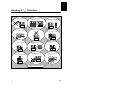
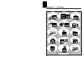


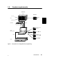


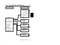
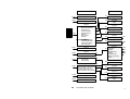
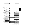


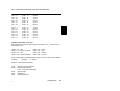
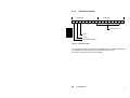
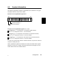


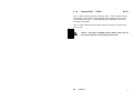


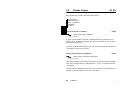


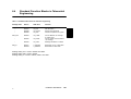
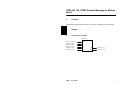
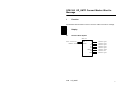

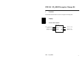

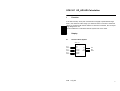


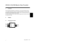
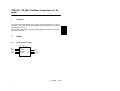


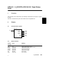
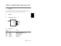
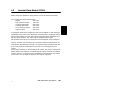
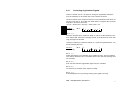

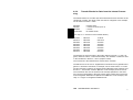


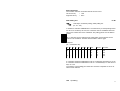


![Variateurs de fréquences (PDF/1,74Mo) [F]](http://vs1.manualzilla.com/store/data/006358628_1-f62170fb25a0bad5b2fc7f3359fee6c0-150x150.png)