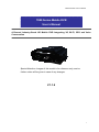
1
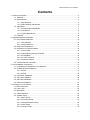
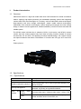
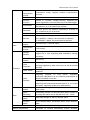
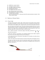
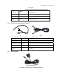
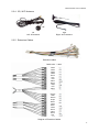
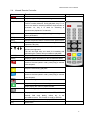
M7000 Series User’s Manual 7000 Series Mobile DVR User’s Manual 4-Channel Industry-Grade HD Mobile DVR Integrating 3G, Wi-Fi, GPS and Voice Conversation Special Attention: Images of this model is for reference only, and no further notice will be given in case of any changes. V1.1.2 1 M7000 Series User’s Manual Contents 1. Product Introduction ................................................................................................................... 4 1.1. Overview .......................................................................................................................... 4 1.2. Specifications ................................................................................................................... 4 1.2.1. Specifications ......................................................................................................... 4 1.2.2. Basic Working Parameters ..................................................................................... 6 1.3. Application........................................................................................................................ 7 1.3.1. Environmental Adaptability ..................................................................................... 7 1.3.2. Precautions ............................................................................................................ 8 1.3.3. Typical Applications ................................................................................................ 9 1.4. Features ......................................................................................................................... 10 2. Appearance and Accessories ................................................................................................... 11 2.1. Front Panel Definitions ................................................................................................... 12 2.1.1. LED Indicator........................................................................................................ 12 2.1.2. Other Definitions................................................................................................... 12 2.2. Rear Panel Definitions.................................................................................................... 12 2.3. Definitions of External Cables ........................................................................................ 13 2.3.1. Power Cable......................................................................................................... 13 2.3.2. Audio/Video Input/output Cables .......................................................................... 14 2.3.3. GPS Module ......................................................................................................... 14 2.3.4. 3G, Wi-Fi Antenna ................................................................................................ 15 2.3.5. Extension Cables ................................................................................................. 15 2.4. Infrared Remote Controller ............................................................................................. 16 3. Host Installation Instructions..................................................................................................... 17 3.1. Unpacking and Inspection of Accessories ...................................................................... 17 3.2. Internal Structure Diagrams............................................................................................ 17 3.2.1. M7001 .................................................................................................................. 17 3.2.2. M7002 .................................................................................................................. 18 3.3. Hard drive Installation..................................................................................................... 18 3.4. SD Card Installation........................................................................................................ 20 3.5. SIM Card Installation ...................................................................................................... 21 3.6. Antenna Installation ........................................................................................................ 21 4. Description of Host Menus........................................................................................................ 22 4.1. Menu Structure ............................................................................................................... 22 4.2. User Login ...................................................................................................................... 23 4.3. Main Menu...................................................................................................................... 23 4.4. Video Playback............................................................................................................... 24 4.5. System Setup ................................................................................................................. 25 4.5.1. Basic Setup .......................................................................................................... 26 4.5.2. Recording Setup................................................................................................... 27 4.5.3. Startup/Shutdown Setup...................................................................................... .30 4.5.4. Alarm Setup.......................................................................................................... 31 4.5.5. Security Setup ...................................................................................................... 33 2 M7000 Series User’s Manual 4.5.6. Network Setup...................................................................................................... 34 4.6. System Information......................................................................................................... 37 4.7. Management Tools ......................................................................................................... 38 4.7.1. Log Management ................................................................................................. 39 4.7.2. Disk Management ................................................................................................ 40 4.7.3. Factory Settings ................................................................................................... 41 4.7.4. Configuration Management .................................................................................. 42 4.7.5. PTZ Management................................................................................................. 43 4.7.6. OSD Setup ...................................................................................................... ….43 4.7.7. System Upgrading................................................................................................ 44 4.7.8. Serial Ports Management ..................................................................................... 45 4.8. Shortcuts Keys ............................................................................................................... 45 4.8.1. F1 Status Menu .................................................................................................... 45 4.8.2. F2 Status Menu (No status menu is shown by pressing F2)................................. 46 5. 3G Application Instructions ....................................................................................................... 46 5.1. General Diagram ............................................................................................................ 46 5.2. Host Parameters Setup .................................................................................................. 47 5.2.1. Center IP and Port Setup: .................................................................................... 47 5.2.2. Setup of Dialing Parameters................................................................................. 48 5.2.3. Viewing Dialing Status .......................................................................................... 48 5.3. PC Software Setup ......................................................................................................... 49 5.4. Precautions .................................................................................................................... 49 6. Host Upgrading Instructions ..................................................................................................... 49 6.1. Upgrading Modes ........................................................................................................... 49 6.2. Upgrading Steps ............................................................................................................. 50 6.2.1. Applications .......................................................................................................... 50 6.2.2. Uboot/ Roofts/ Kernel ........................................................................................... 50 6.2.3. SCM .....................................................................................................................50 6.2.4. Viewing Version Number ...................................................................................... 50 7. FAQs ........................................................................................................................................ 51 7.1. Questions on 3G ............................................................................................................ 51 7.2. Questions on Wireless Module....................................................................................... 51 7.3. Questions on Wi-Fi ......................................................................................................... 52 7.4. Questions on Recording ................................................................................................. 52 7.5. Questions on Connection ............................................................................................... 52 7.6. Questions on Alarm ........................................................................................................ 52 7.7. Others............................................................................................................................. 53 3 M7000 Series User’s Manual 1. Product Introduction 1.1. Overview ANV-M7000 series is a high-end mobile hard drive DVR dedicated for mobile surveillance market. Applying high-speed processor and embedded operating system and integrating various state-of-the-art technologies of IT industry, such as audio/video codec technologies, large-capacity hard drive storage technologies, stream media network technologies, video/audio noise reduction technologies, mature damping technologies and wide voltage design, it features concise appearance, flexible installation, powerful functions and safe and reliable system. The M7000 series is divided into 2 subseries, M7001, local version, and M7002, network version; the local version supports only local video recording functions instead of network functions like 3G and Wi-Fi; and applying functional modular design, the network version has optional features that allows customization of functions like 3G type, Wi-Fi and GPS, etc. Product picture: 1.2. Specifications 1.2.1. Specifications Item Description OS Linux Graphics Operation Interface System parameters can be set through external display and remote controller Security Management 2-level management for user password, administrator password, supporting encrypted transmission Video and Preview Video Output OSD Input, 4-channel video input, 1channel video output; 1.0Vp-p, 75Ω Character superposition function, information superposition of time and date, device ID and GPS, etc. 4 M7000 Series User’s Manual Audio Video Compression Format Compression coding. Applying Hisilicon hi-performance processor. Dual-Stream Supported Preview Function Preview of 1-channle, 4-image stitching, supporting full screen triggered by event and switching of stitched images Frame Rate PAL: 100 frames/s, up to 25 frames/s per channel; NTSC: 120 frames/s, up to 30 frames/s per channel Resolution CIF, HD1 and D1 for selection, supporting 2 channels of D1+ 2 channels of CIF at the most Quality Grade 1 to grade 5 for selection (descending) Bit Rate CIF: 256Kbps ~ 1.5 Mbps, 8-level bit rates for selection HD1: 600Kbps ~ 2 Mbps, 8-level bit rates for selection D1: 800Kbps ~ 3Mbps, 8-level bit rates for selection Audio Output Input, Compression Format G.726 coding Storage Medium Supporting one 2.5” hard drive and one SD card, which supports up to 32G, supporting data redundancy storage technology; File Format/ System ASF/FAT32 Video Strategies Recording at startup by default, supporting timed recording, recording triggered by alarm and event, as well as manual recording Video Search Searching by time, type, storage device and other conditions Recording Supporting playback on local device, supporting synchronous playback of up to 4 channels and analysis on vehicle information in the files Video Playback Alarm Output Alarm 4-channel input, 1-channel output Supporting fast forward, fast backward, play and pause, supporting fast forward and fast backward at 2x, 4x, 8x and 16x speed, supporting file play from selected time Input/ 6-channel on/off signal alarm input, 1-channel on/off signal alarm output Alarm Recording Prerecording function 15 seconds before alarm, duration of recording after alarm can be adjusted from 30s ~ 30min Storage Space Alarm Supporting settings for alarm of storage space Function Alarm GPS overspeed alarm, acceleration alarm, motion detection alarm Communication Ports RS232, RJ45 10M/100M self-adaptable network interface Wireless Transmission Embedded 3G wireless transmission module, WCDMA, 5 M7000 Series User’s Manual (Optional) CDMA2000, TD-SCDMA system for selection; Compatible with GPRS, EDGE; Embedded Wi-Fi module; GPS (Optional) Supporting external GPS Remote Data Transmission Channel Selection Supporting 3G, Wi-Fi data channel transmission, supporting Wi-Fi priority transmission strategy; supporting remote downloads of back-end recording strategies; PTZ Control Supporting PTZ control realized by local ad client software; Parameter Configuration Supporting parameter configuration functions for mobile DVR coding channel; G-Sensor Embedded System Upgrading Supporting SD card, hard drive upgrading and remote upgrading Power Supply and Power Consumptio n Operating Environment Power Supply 1. ACC on/off 2. Hard drive lock on/off 3. Delayed shutdown 4. Timed on/off Input Voltage DC:+8V ~ +36V Output Voltage +12V@4*0.5A; [email protected] Power-off Protection With patented UPS power supply continuous working technology, it can work for 3~5 seconds after external power supply is cut so that the intactness of video data can be kept upon sudden power failure Power Consumption <10W in normal operation; <0.5W in standby mode Temperature Normal: 0℃ ~ +60℃; upon hard drive preheating: -25℃ ~ +60℃ Humidity 10% to 95% Dimensions 160(W) x62(H) x200(D) mm. Weight Net: 2200g, Gross: 3500g Product Module Options: M7000 Series Product Type SD card HARD DRIVE GPS 3G G Sensor Wi-Fi (Customized) M7001 × ∨ × × ∨ × M7002 ∨ ∨ ∨ ∨ ∨ ∨ 1.2.2. Basic Working Parameters Item Working Parameters Description 6 M7000 Series User’s Manual 8 ~ 36V Input voltage at +8V~+36V, the device will be automatically turned off and enter the protection mode if the voltage is lower than 8V for a long time; if the voltage is higher than 36V for a long time, the voltage protection device will block the power supply. 12V Output voltage12V (+/-0.2V), Max. current: 2A. 5V Output voltage5V (+/-0.2V), Max. current: 0.5A. Al outputs are provided with overcurrent protection, when the output current is greater than 1.2 times of the preset max. current for a long time: the output will be cut automatically and the output will be resumed upon normal loading. ≤6V Vehicle key off. ≥7.5V Vehicle key on. 75Ω Impedance of 75Ω for each channel of video. 1Vp-p Outputting a 1Vp-p CVBS analog signal. 0 ~ 2V Low-level alarm. Above 5V Hi-level alarm. RS232 Serial Ports Standard Interface Supporting 2 RS232 ports GPS Pedestal External Antenna Antenna interface with embedded GPS Ethernet Interface Standard Interface Standard RJ45 interface, with indicator. SD Card Interface Standard Interface Compatible with commerciall avaiblable brands. Working Temperature 0℃~ +55℃ Hard drive heating -25℃ ~ +55℃ Power Supply Input Output Voltage Vehicle Key Signal Video Impedance Input Video Output I/O Interface Antenna 1.3. Application 1.3.1. Environmental Adaptability M7000 is applicable to various applications, and the indexes are detailed as follows: Item Index Upper limit of temperature for storage 65℃ Upper limit of temperature for operation 55℃ 7 M7000 Series User’s Manual Lower limit of temperature for storage -40℃ Lower limit of temperature for operation 0℃, or -25℃ with hard drive heating module Working altitude –300 ~ 3048m (10, 000 ft) Transmission altitude –300 ~ 12, 192m (40, 000 ft) RH 20%~95% Max. temperature gradient 20℃/h Vibration threshold (Unpowered) No greater than 5mm p-p (5 – 22Hz) 49m/s2 (5.0G) (22 – 500Hz) Vibration threshold (Normal operation) No greater than 1.0mm p-p (5 - 22Hz) 9.8 m/s2(1.0G) (22 – 500Hz) Impact threshold (Unpowered) No greater than 1200G, (11, 760m/s2) (duration 1 ms, 1m height, semi sine wave) Impact threshold (Normal operation) No greater than 500G, (4, 900m/s2) (duration 2 ms, semi sine wave) IP of enclosure IP54 1.3.2. Precautions To ensure safe use, satisfactory performance and extended service life of the product, please pay attention to the following when installing and operating the device: 1) 2) 3) During the installation and operation of the device, make sure to observe all criteria for electronic products as well as requirements for vehicles and other connection devices; Power supply and grounding: a) The direct input range of the power supply of the device should be DC 8V to 36V, avoid reverse connection or short circuit of output. Please pay attention to the power supply capacity of the power cable. b) Even if the device is turned off, there’s still electricity left inside it, please prevent short circuit. Before connecting to other external devices, please cut the connection between the device and the power supply; c) The output voltage of the device is 12V, only used for power supply of the camera, please do not enclose any device that are not allowed to be used on the device; d) The sensor input mode of the device is leveling, if the external voltage is less than 2V, it is regarded to be low level, and the voltage between 5V~30V is regarded to be high level, and the voltage over 30V will cause abnormal data collected by the device or damage of the device. The voltage higher than 2V and lower than 5V is illegal. e) Correctly connect the earth wire of the device to the earth wire of the vehicle to constitute the circuit; f) If the device is to be laid aside for a long time, it is better to completely cut the power supply to extend the service life; Humidity requirements: a) The device should be installed in dry environment, avoiding humid, dripping and spraying of water. Do not install the device at sunken locations with the possibility of water accumulation or wet locations subject to liquid dripping; 8 M7000 Series User’s Manual b) 4) 5) Do not touch the device by wet hand or touch the device while standing in water or other water sources, which may cause electric shock; Installation locations: a) To extend the service life of the device, try to install the device at locations on the vehicle subject to slight vibration. b) The device shall be installed in ventilating parts of the vehicle: when installed on a level plane, the device shall be kept 6 inches (15cm) away from other objects to facilitate ventilation and cooling; do not install the device in an enclosed space (the trunk, for instance). c) External cables of the device should be provide with sufficient spacing and flame-retardant housing to prevent the cable from bending or abrasion due to vibration and thus cause leakage of electricity; d) Keep the device from heat source of the vehicle or sundries, it is strictly prohibited to place anything on the device. e) The device can only be installed horizontally or vertically sideways (please consult the manufacturer if you need to install it along another direction), installation at any other angle may damage the device and is strictly prohibited. Device safety: a) Prevent the driver or passenger from intervening or damaging parts, cameras, cables and other accessories of the device, keep the device away from other restricted vehicle parts; b) Starting the vehicle while installing components, cameras, cables and other accessories of the device may cause damage of the device, keep the vehicle still during the installation and prevent it from dropping. 1.3.3. Typical Applications Applications: bus, school bus/staff bus, logistic trucks, coach bus, taxies, train/metro/light rail, vessels Topological graph of main applications; 9 M7000 Series User’s Manual Mobile Remote Surveillance System Solution Vehicle management Client Stream media Server User management 1.4. Features z z z z z z z z z z z H.264 video code compression, dual stream output; G.726 audio compression format, 4-channel audio input, 1-channel audio output. Power-off protection in emergency, adopting special UPS technology which ensures the device to work for 3-5 seconds after the external power supply is cut, thus ensure complete video data and avoid file damage; Real-time local recording, multiple formats for selection, supporting full screen of single channel or multi-window stitching upon accidents; Switch signal interface, 6-channel alarm input, 1-channel alarm output; PTZ control; Multiple recording modes: record upon startup, timed recording and triggered recording; Universal video file formats: applying ASF format, which can be played with the universal software VLC or the supplied playback software, supporting 1-channel or 4-channel synchronous playback; Data storage, supporting a 2.5” hard drive and 1 SD card with the capacity up to 32G; supporting dual-stream mirror image video recording, SD card recording upon loss of hard drive, supporting hard drive heating, applying drawer-type hard drive box; Wide voltage design, 8-36V DC wide voltage input, suitable for various vehicles; DC 5V/0.5A, 12V/2A output; Rapid startup, capable of entering normal working mode within 25 seconds after startup; supporting on/off with key switch, timed on/off and delayed on/off, etc.; 10 M7000 Series User’s Manual z 2. Optional functions: 3G wireless transmission; Wi-Fi wireless transmission; GPS, G-sensor acceleration sensor, with precise time correction; IP calling; Dialing; Appearance and Accessories Front View: Back View: 11 M7000 Series User’s Manual 2.1. Front Panel Definitions 2.1.1. LED Indicator z z z z z z z z z z [PWR]Power supply state indicator: LED on ─ system powered. [ALM]Alarm indicator. [REC]Recording indicator: LED ON - recording. [HD]Hard drive indicator: LED ON -hard drive successfully loaded; LED out -failure loading hard drive; LED flashing -hard drive recording. [SD]SD card indicator: LED ON -SD card successfully loaded; LED out-failure loading SD card; LED flashing-SD card recording. [GPS]GPS signal indicator. [ERR]Error indicator. [V-Loss]Video loss indicator: LED ON -1 or more video inputs lost. [HTR]Heating indicator. [NET]Network indicator. 2.1.2. Other Definitions z z z z [IR]IR receiver for receiving signals from the remote controller. [LOCK]Hard drive lock, the device can be started only after being locked and be automatically in the standby status after being unlocked. [MIC]MIC input. [EAR]Earphone output. 2.2. Rear Panel Definitions 12 M7000 Series User’s Manual ● ● ● ● ● ● ● ● [PWR]Power supply interface. [*] [GPS]GPS module interface. [EXTEND I/O]Extension interface. [RJ45]Network interface. [AV IN]Audio/video input interface. [AV OUT]Audio/video output interface. [*] [WI-FI]Wireless LAN antenna interface. [*] [3G]3G antenna interface. Note: [*] indicates that Wi-Fi, 3G antenna and GPS module interface are used for 7002 series network models. 2.3. Definitions of External Cables 2.3.1. Power Cable The figure below shows the power cable, and the red wire and the black wire are directly connected to the battery jar of the vehicle. The red wire is connected to the positive pole, and the black to the negative pole. The yellow wire is connected to the ignition wire when the on/off mode is set to ignition mode. The device will be automatically turned on once the vehicle key switch is turned on and automatically turned off when the vehicle key switch is turned off. The yellow wire is connected to the position for the vehicle key to turn on all dashboard lights (the one before the position to start the motor). Note: 1) Before connection, confirm the voltage of the battery jar between 12 V —24 V , or the device may be burnt; UU UU UU UU 2) After the connection, pay attention to the insulation between power cables to prevent short circuit of the power supply that may burn the battery jar. 3) The yellow wire must be connected to the ignition wire, otherwise, the device will not support ignition mode. 4) Note: the mobile device must be directly connected to the positive and negative poles of the battery jar without any earth, which may generate negative pulse and disturb normal operation of the device. Power cables for the positive and negative poles must have the diameter of above Φ1.5. 13 M7000 Series User’s Manual Power cable The figure above shows the actual power cable Circuit Color Name Description Black BAT- Black wire for grounding Red BAT+ Red wire for power supply Yellow ACC Yellow wire for ACC 2.3.2. Audio/Video Input/Output Cables Left Right Left: Audio/Video Input/Output Cable Right: Tie line. Interface Name Description Video Input VIN1~VIN4 4 video inputs, BNC connector as the interface Audio/video output VOUT 1 video output, BNC connector as the interface Audio input AIN1~AIN4 4 audio inputs, RCA connector as the interface Power supply output DC 12V power supply output, DC connector as the interface 2.3.3. GPS Module GPS module antenna The figure above shows the actual GPS module 14 M7000 Series User’s Manual 2.3.4. 3G, Wi-Fi Antenna Left Right Left: 3G antenna Right: Wi-Fi antenna 2.3.5. Extension Cables Extension cables Cable color Label White White White White Black Grey Red Yellow Black Grey Red Yellow Orange Pink Black Purple Brown White White White Black Yellow Black Red Diagram of Extension Cables 15 M7000 Series User’s Manual 2.4. Infrared Remote Controller Key Function Image Remote on. [LOGIN] Login the system for parameter settings. [0-9] [0-9] keys: In the setting status, the numeric keys are used for number selection. During playback, keys 1, 2, 3 and 4 are used for switching between single window of channels 1-4, key 5 is used for switching to synchronous playback of 4 channels. [-][+] Increasing and decreasing (scrolling) in setting some menu parameters. [DEL] Backspace when inputting numbers. [EXIT] Exits to the preview menu or returns to the parent menu. [ENTER] Confirms parameter selection and settings as well as operations like play. ▲, , , Arrow keys that move the cursor upward, downward, leftward and rightward. The left and right keys are used for increasing and decreasing the volume during surveillance playback. [GOTO] Plays the video from the selected time. [INFO] Displays system information in the surveillance status. Fastback, 2x/4x/8x/16x for selection, press once to switch to the next speed in order, press [Play] to resume normal speed; Plays the video during playback. Fast-forward, 2x/4x/8x/16x for selection, press once to switch to the next speed in order, press [Play] to resume normal speed; Starts recording in manual recording mode. Stops recording in manual recording mode. Stops playing the video in playback mode. Pauses during playback. [F1] Displays information like acceleration GPS, Wi-Fi, 3G module, SIM card, dialing, online, etc. in the surveillance menu. This function is used for FB7002. [F2] Monitors single channel and displays PTZ information. [F3] Reservation 16 M7000 Series User’s Manual 3. Host Installation Instructions 3.1. Unpacking and Inspection of Accessories After unpacking, please check the device for distortion or any other damage, in which case please stop using the device and contact your supplier. There is a packing list in the carton, please check all accessories of the main device for completeness according to this list. 3.2. Internal Structure Diagrams 3.2.1. M7001 Audio/video output interface Extension interface Power interface Audio/video output interface Signal transfer board 17 M7000 Series User’s Manual 3.2.2. M7002 3G antenna interface Wi-Fi antenna interface GPS antenna interface SD card slot SIM card slot Signal transfer board 3.3. Hard Drive Installation Hard drive installation steps: Step 1. Unlock the hard drive and remove the hard drive enclosure Step 2. Remove the bolts (altogether 7) and remove the 6 bolts on the bottom of the hard drive enclosure 18 M7000 Series User’s Manual Remove 1 bolt on the back side of the enclosure Step 3. Install the shock pads. Install the shock pads on both sides according to the installation diagram of the hard drive. The hard drive is not fixed by bolts and will depend on the rubber shock absorbing covers and shock pads on both sides. Step 4. Install the rubber shock absorbing covers Mount the rubber shock absorbing covers on both sides of the SATA hard drive, with the side of the cover with the lug close to the PCB. Connect power cable smoothly. Ensure reliable installation of cable interfaces of different components. 19 M7000 Series User’s Manual Step 5. Close the enclosure and fasten the screws Note: Please note that the bolts on the sides cannot be mixed with that on the bottom and ensure tightness of all bolts; always remember to lock the hard drive after installation, otherwise, the device may not be started. 3.4. SD Card Installation Open the hard drive lock with the key and remove the hard drive enclosure, and remove the SIM card over, then appears the SD card slot as shown in the figure below. Since the SD card slot is close to the 3G module, to facilitate inserting and removing the SD card, it is recommended to remove the 3G module before inserting or removing the SD card, and then align the SD card to the SD card interface and press to the end (pay attention to the front and back sides of the SD card when inserting it, after inserted, the SD card should have a notch at the upper right corner). Press the card and pull out the 3G module Remove the 3G module 20 M7000 Series User’s Manual Insert the SD card 3.5. SIM Card Installation The location of the SIM card slot is shown in the figure below, first, open the hard drive lock with the key and remove the hard drive enclosure, do not pull up the SIM card holder, install the SIM card to the proper position and close the SIM card cover and then fasten the bolts. Note for removing the SIM card cover: open the hard drive lock with the key and remove the hard drive enclosure, remove the bolts (on the upper left corner and on the lower right corner of the SIM card), and then remove the SIM card cover. Install SD card here Install SIM card here Locations of SD card slot and SIM card slot 3.6. Antenna Installation Interfaces for Wi-Fi and 3G antennas are equipped on the back panel of the device for connection of corresponding antennas, as shown in the figure below: 21 M7000 Series User’s Manual Wi-Fi antenna interface 4. 3G antenna interface Description of Host Menus 4.1. Menu Structure The user may control various functions of the device through a series of menu operations, in this chapter, we will briefly introduce the structure of such menus, and detailed description will be provided in subsequent chapters. All videos Video playback Alarm video Basic settings Recording settings System settings On/off settings Alarm settings Security management Login Network settings System information Log management Disk management Factory settings Management tools Configuration management PTZ management Display settings System upgrading Serial port management Menu Structure 22 M7000 Series User’s Manual 4.2. User Login z z z z When the password is set to “enabled”: press the [ENTER] button after startup of the main device to enter the login menu (as shown in the figure below), where it is required to input the correct user password or administrator password; Move the cursor to “Login” and press [ENTER] to enter the system main menu; Move the cursor to “Cancel” and press [ENTER] to quit the login menu. When the password is set to “Disabled”: press the [ENTER] button after startup of the main device to directly enter the system main menu without login; Note: after restoring to factory settings, the password for ordinary user is 000000 and that for administrator is 888888; You can only view the system menu if you log in with the user password and will have no privilege to modify the parameters; if you log in with the administrator password, you will be able to both view the system menu and modify settings. LOGIN DEV ICE NO.:00000 USER NAME : user / admin PASSWORD : ****** LOGIN CANCEL 4.3. Main Menu After user login, you will enter the following main menu, consisting of: PLAYBACK, SYSTEM SET, SYSTEM INFO, MANAGE TOOL. 23 M7000 Series User’s Manual 4.4. Video Playback In the main menu, press the arrow keys to select the video to playback, and press [ENTER] to enter the REC SEARCH interface. REC SEARCH 01 02 03 04 05 06 07 08 09 10 11 12 13 14 15 16 17 18 19 20 21 22 23 24 25 26 27 28 29 30 31 REC TYPE:ALL/ALARM DISK SELECT:HDD/SD DATE:2011-05-27 START TIME:00:00 END TIME:23:59 SEARCH Note: After entering the REC Search interface, the system will automatically search the date of the video existing in the current month. The cursor cannot move in this table, the dates in yellow are those with existing video records. You can only search files of one day each time. When the month inputted in is not the current month, the status list will be refreshed “REC TYPE”: Press [Enter] to select types to recall: All videos\Alarm video. All videos by default. “DISK SELECT”: Press [Enter] to select disk: SD\HDD. HDD by default. “DATE”: Press the numeric keys to input the date, the current date by default. “START TIME”: Press the numeric keys to input the time, 00: 00 by default. 24 M7000 Series User’s Manual “END TIME”: Press the numeric keys to input the time, 23: 59 by default. “SEARCH”: Move the cursor to “search” and press[Enter] to enter the following menu of SEARCH RESULT. SEARCH RESULT DATE: 2011-05-27 TYPE Normal Normal Normal Normal Alarm Alarm Alarm Alarm FIRST z z RES START END CH SIZE D1 D1 CIF CIF D1 D1 CIF CIF 15:30 15:30 15:30 15:30 16:10 16:10 16:10 16:10 16:00 16:00 16:00 16:00 16:12 16:12 16:12 16:12 1 2 3 4 1 2 3 4 154M 53M 100M 98M 7M 7M 9M 10M UP DOWN LAST Press the arrow keys to select the video to be checked, press [ENTER] to play the video and press [EXIT] to return to the parent menu. Press the arrow keys to select “Home”, “Previous”, “Next”, “End”, and press [ENTER] to display page turning information. 4.5. System Setup In the main menu, press the arrow keys to select the SYSTEM SETUP menu, and press [ENTER] to enter the following SYSTEM SETUP menu. The menu mainly consists of the following submenus:.BASE SET, REC SET, POWER SET, ALARM SET, SECURITY, NETWORK. SYSTEM SETUP 25 M7000 Series User’s Manual 4.5.1. Basic Setup This menu is mainly for settings of basic information of the system. BASIC SETUP DATE TYPE:YMD/DMY/MDY TIMEZONE:GMT +08(00~+12 / -01~-12 ) DATE:2011-05-27 09:01:30 IDLE TIME:30(30~3600s) DEVICE NO. :11111 COMPANY NAME:Company Name VEHICLE NO.:00000 DRIVER NAME:Driver Name BUS LINE NO.:Bus line no. SAVE Date Format This is used for selecting date format, i.e., year-month-date, date-month-year, month-date-year. press [ENTER] for selection. Time Zone This is used for selecting time zone, GMT+08 by default, press [ENTER] or [-] [+] for selecting other time zones. Date/Time This is used for modifying the current date, press numeric keys for input Idle Time This is used for setting menu wait time, when the preset time is exceeded, the current user will be logged out automatically and the system will return to the surveillance status. The default wait time is 30 seconds, and the range is 30~3600 seconds, which can be inputted with the numeric keys. Device No. This is used for occasions where one remote controller is used for controlling multiple devices, adopting different passwords and device IDs may avoid mutual interference. When setting the device No., press DEL to delete the original number and press the numeric keys to input the number, which must be in 5 digits. Enter security settings to set password corresponding to the device No. “Company Name”, ”License Plate Number”, ”Driver Name”, ”Route Number” Press [Enter] to enter keypad menu, press the arrow keys to move the cursor, and press [Enter] to select corresponding letters and digits to be inputted. Upon completion of settings, press the Save button to save the settings. 26 M7000 Series User’s Manual 4.5.2. Record Setup This menu is for settings of recording parameters. RECORD SETUP SYSTEM:PAL/NTSC RESOLUTION:D1/HD1/CIF AUDIO :ON/OFF TIME SLICE:15/30/45/60 (M) RECORD MODE:AUTO/TIMED/ ALAR M/MANU AL BITRATE: D1(2048 /2000 /1600 /1400 /1200 /1000 / 800 /600)HD1(1500 /1300 /1100 /900 /800 /700 /600 /500)CIF(1200 /1000 /800 /700/ 600/ 500/ 400 /300) SD FUNCTION: NO REC/MIRR REC/ LOST REC CHANNEL QUALITY CH1(1~4) 1(1~5) TIME LIST OVERWRITE: NORMAL/NONE/ALL ALARM DELAY: 30(30~1800S) FRAME RATE 25(1~30) SUB-STREAM RECORD ON/OFF SAVE System PAL/NTSC, press [ENTER] to input. Record Mode Record upon Startup (default)/Timed Recording/Alarm Recording/Manual Recording, press [ENTER] to input. There are 4 modes: Startup, Timed, Manual and Alarm, and the default mode is Startup Startup: Automatically starts recording at startup of the device Timed: Automatically starts recording at the set time Manual: After startup of the device, press the Record key to start recording Alarm: After selecting “Enable” and enable “Record” and “Output” in Alarm Settings, the system will automatically start recording alarm files Bitrate z z z z The data traffic per second, the default value is 1600KBPS, press [ENTER] or press [-][+] for selection. Resolution D1/HD1/CIF, D1 by default, press [ENTER] to input. Audio To set whether to encode audio synchronously while video recording or not. Select enable/ disable, and press [ENTER] to input. Time Slice Length of each section of video recorded in continuous recording status, 15/30/45/60, [ENTER] to input. SD Function 27 M7000 Series User’s Manual No recording / Mirror image recording / Record upon loss, press [ENTER] to input. 1) 2) 3) No recording: recording is only available for hard drive, even if it’s full, the SD card will not be used for recording. Mirror image recording: When the hard drive is recording video with the main stream, the SD card is recording video with the sub-bit stream; When the hard drive is not recording, the SD card will not record; the recording will not be started without the SD card; and the recording with SD card will not be started without the hard drive; Record upon loss: in case hard drive error or absence of the hard drive, the SD card will record video with the main stream; Note: If both the hard drive and the SD card exist, priority should be given to the hard drive. Video channel settings This is used for setting recording parameters of each channel, press [ENTER] to input. 4 channels, image levels from 1~5, with level 1 as the highest and level 5 as the lowest, frame rate: 1~25 frames for PAL and 1~30 frames for NTSC; recording can be enabled or disabled. Video overwriting strategy Options: “Off, Normal Video, All Videos”, for setting whether to automatically overwrite the video, and press [ENTER] to input. 1) 2) 3) Off: the video will not be automatically overwritten when the hard drive or SD card is full; Normal Video: normal video files instead of alarm video files of the hard drive or SD card will be automatically overwritten; All Videos: both normal video files and alarm video files of the hard drive or SD card will be automatically overwritten. Note: The hard drive and the SD card are overwritten circularly. Delay for alarm recording 30 seconds by default, adjustable within the range 30 seconds~1800 seconds, press numeric keys to input. Timer list settings Move the cursor to ”Record Time List”, and press [ENTER] to enter the following list menu: 28 M7000 Series User’s Manual RECORD TIME LIST DATE EVERYDAY MONDAY TUESDAY WEDNESDAY THURSDAY FRIDAY SATURDAY SUNDAY TIME 1 TIME 2 00:00-00:00 00:00-00:00 00:00-00:00 00:00-00:00 00:00-00:00 00:00-00:00 00:00-00:00 00:00-00:00 00:00-00:00 00:00-00:00 00:00-00:00 00:00-00:00 00:00-00:00 00:00-00:00 00:00-00:00 00:00-00:00 SAVE 1) 2) The Record Time List will only be enabled in the timed recording mode, which is selected in the on/off mode, when the device is turned on, it will start recording at the set time automatically and stop recording upon completion of the task. The user may set the recording time in his preferred way, period 1 and period 2 are not intercrossed, each period is inputted with the numeric keys; move the cursor to a certain period and input numbers, period 1 is the first period of the recording cycle of any day, and period 2 is the first period of the recording cycle of any day, 00: 00---23: 59 for 24-hour time list settings, and upon completion, press Save to save the settings and return to the Recording Settings menu. Upon completion of recording settings, press the Save button to save the settings. Sub-Stream Move the cursor to “sub-stream”, press [ENTER] to enter the follow menu of Sub–stream Setup: SUB-STREAM SETUP RESOLUTION:CIF/QCIF QUALITY: Medium/High/Low BITRATE: 16/24/32/48/56/64/80/96/112/128/160/176/200/280 FRAME RATE: 01/01/01/01/02/02/03/04/05/07/10/13/15/20 SAVE 29 M7000 Series User’s Manual Resolution CIF, press [ENTER] to input. Quality Hi/Med/Low, press [ENTER] to input. Bitrate 16/24/32/48/56/64/80/96/112/128/160/176/200/280 bits, press [ENTER] to input. Frame rate 01/02/03/04/05/07/10/13/15/20 frames, corresponding to bit rate, press [ENTER] to input. Upon completion of settings, you must press the Store button to save settings. 4.5.3. Power Setup Set on/off parameters. POWER SETUP POWER MODE: DELAY POWER OFF: DELAY TIME: POWER ON TIME: POWER OFF TIME: ACC / TIME ON/OFF 5(3~240)(M) HH:MM:SS HH:MM:SS SAVE On/off mode Set on/off mode and press [ENTER] to input. 1) TIME mode: turns on or off the device according to the on/off period set by the user. 2) ACC mode: turns on/off the device according to the vehicle key signals. Delayed off The device will be turned off upon the delayed off time, and then press [ENTER] to input. Delay time The delay time can be set within the range 3~240 min, press DEL to clear the original number and press numeric keys to input. Timed on time Set the time to turn on the device in the timed mode, press numeric keys to input. Timed off time 30 M7000 Series User’s Manual Set the time to turn off the device in the timed mode, press numeric keys to input. Upon completion, press the Save button to save settings. Note: There’s no difference in the length of timed on time and timed off time, the whole period is a cycle. 2 4.5.4. Alarm Setup Set output parameters upon alarm. ALARM SETUP ENABLE PWL RECORD FUNCTION I /01 ON HIGH ON LEFT/RIGHT I /02 ON HIGH OFF MIDDLE I /03 ON LOW ON BRAKE I /04 OFF LOW OFF FRONT I /05 OFF HIGH ON POSTERN I /06 OFF LOW ENABLE OFF PWL OFF HIGH INPUT OUTPUT RELAY OUTPUT SAVE SPEED G-SENSOR BACKING MOVE DETECT Alarm input Supporting synchronous input of up to 6 channels of alarm. “Enable”: Set whether to enable the function upon alarm, press [ENTER] to input. “PWL”: set high\low level, press [ENTER] to input. “Record”: set whether to start alarm recording of this channel, press [ENTER] to input. Alarm output Supporting synchronous output of up to 1 channel of alarm. “Enable”: Set whether to enable the function upon alarm, press [ENTER] to input. “PWL”: set high\low level, press [ENTER] to input. GPS Overspeed Move the cursor to “overspeed” and press [ENTER] to enter the following menu of overspeed alarm: 31 M7000 Series User’s Manual GPS OVER SPEED THRESHOLD:60(0~999)(km/h) ENABLE:ON/OFF SAVE Threshold: 60km/h by default, adjustable within the range of 0~999. press DEL to delete the original number, press numeric keys to input. Enable: On/Off, press [ENTER] to input; z On: when the speed of the GPS exceeds the threshold value, the alarm recording will be started and alarm logs will be recorded; z Off: when the speed of the GPS exceeds the threshold value, neither the alarm recording nor the alarm logs will be started Upon completion, press the Save button to save settings. Acceleration Move the cursor to “G-Sensor”, press [ENTER] to enter the following menu of G-Sensor settings: G-SENSOR ALARM SWITCH: ON/OFF THRESHOLD VALUES X: 2.00 g Y: 2.00 g Z: 2.00 g STATUS: X= -0.12 ADJUST Y= -0.03 Z= -0.01 SAVE “Threshold”: Set values of X, Y and Z directions within the range of 0.00g--9.99g, press DEL to delete the original number, press numeric keys to input. 32 M7000 Series User’s Manual “Alarm Switch”: set whether to enable or disable G-sensor alarm, press [ENTER] to input. z Alarm on: In the recording status, when any of the directions of X, Y and Z exceed the “Threshold”, the alarm recording and the alarm logs will be started. z Alarm off: In the recording status, when any of the directions of X, Y and Z exceed the “Threshold”, neither the alarm recording nor the alarm logs will be started. “Adjust”: Before initial use of the device, you need to click on “Adjust” on the menu for calibration of X/Y/Z values, press [ENTER] to input. Upon completion of the calibration, the current X, Y, Z values will be zeroed. Upon completion, press the Save button to save settings. Motion Detection MOTION DETECTION CHA NNE L LEVEL ENABLE AREA CHI/ CH2/CH3/ CH4 HIGH/MID/ LOW OFF/ON SETUP SAVE Channel: CH1/CH2/CH3/CH4, press [ENTER] to input; Level: Hi/Med/Low, press [ENTER] to input; Enable: Enable/Disable, press [ENTER] to input; On: Upon alarm, the alarm recording and the alarm logs will be started; Off: Upon alarm, neither the alarm recording nor the alarm logs will be started; Area: Set area and press [ENTER]. Upon completion, press the Save button to save settings. 4.5.5. Security Setup Setting login password 33 M7000 Series User’s Manual SECURITY PASSWORD: ON/OFF USER PWD: ****** CONFIRM: ****** INPUT NOT SAME! ADMIN PWD: ****** CONFIRM : ****** SAVE NOTICE:PASSWORD IS 6 NUMBE RS! Password Set whether to enable the login password, and then press [ENTER] to input. z On: When log in with the Admin password, Admin\User password can be set; When log in with the user password, only the User password can be set, press numeric keys to input, the passwords inputted twice should be consistent. z Off: Password cannot be set. After entering the menu, one can directly enter the main menu without login. Note: If there are multiple devices with the same power supply for recording, please set different password and device ID for each device so as to avoid disturbing other devices when operating one of them, the device ID may be modified in Basic Setup. 4.5.6. Network Setup NETWORK SETUP LOCA L SETUP IP ADDRESS: 192. 168. 000. 192 NETMASK: 255. 255. 255. 000 GATE WAY: 192. 168. 000. 001 MAC: 00.44.53.75.55.56 CENTER SETUP TYPE: IP/DOMA IN DOMAIN: www.123.cn 3G SERVER :192 . 168 . 001 . 000 PORT:5678 WIFI SERVER :192 . 168 . 001 . 000 SAVE 3G DDNS PORT:5678 WIFI Local setup Set the device IP address, netmask, gateway, MAC, etc., which should be within the same subnet with the center server, as shown in the figure above. 34 M7000 Series User’s Manual WAN connection: No need to set local network. Center setup Connection within the LAN Set the center server IP address, which should be within the same subnet with the device IP, the port number of 5678 is fixed. WAN connection Server IP Set WAN IP Port number For accessing with routers, port mask 5678 on the router must be set. Domain name Targeting some users with dynamic IP, the user may apply for a DDNS account on line and set corresponding domain name. (e.g.: www.123.cn ) 3G Setup HU UH Move the cursor to “3G Setup”, and press [ENTER] to enter the following menu of 3G settings: 3G SETUP 3G FN:ON / OFF TYPE:WCDMA / EVDO / TD TRIGGER NO.1: LINK MODE:NORMAL/ TRIGGER NO.2: TRIGGER CALL NO.1: VOICE FN: OFF/ON CALL NO.2: CENTER NO.: *99# / #777 / *99***1# APN: 3gnet / ctnet / cmnet USER NAME: card PASSWORD: **** SAVE 3G FN Set whether to enable or disable wireless communication, and press [ENTER] to input. Type Set wireless module type, WCDMA, ECDO or TD, and press [ENTER] to input. Link mode Triggering mode, Calling-Dialing, Send SMS-Stop Dialing. Normal link mode, direct dialing. Trigger No. 1 and 2 are inputted with the numeric keys. Voice FN Set whether to enable or disable voice function and press [Enter] to input. Call No. 1 and 2 are inputted with the numeric keys. “APN” 35 M7000 Series User’s Manual Set data access point, and press [Enter] to input, and then enter the keypad interface, move the cursor and press [Enter] to select corresponding letters for input. “User Name”, ”Password” Set the User Name and Password of 3G service, and press [Enter] to input, and then enter the keypad interface, move the cursor and press [Enter] to select corresponding letters for input. Upon completion, press the Save button to save settings. DDNS Setup Move the cursor to ‘DDNS’, press [ENTER] to enter the following DDNS menu: DDNS SETUP DDNS: ON / OFF TYPE: DYNDNS / 3322 USER NAME: PASSWORD: DOMIAN: SAVE DDNS On/ Off, press [Enter] for selection. Type DYNDNS/3322, press [Enter] for selection. “User Name”, ”Password” Set the User Name and Password of DDNS, press [Enter] to input, and then enter the keypad interface, move the cursor and press [Enter] to select corresponding letters for input. Domain name Input corresponding domain name, press [Enter] to input, and then enter the keypad interface, move the cursor and press [Enter] to select corresponding letters for input. 15B Upon completion, press the Save button to save settings. Wi-Fi Setup Move the cursor to ‘Wi-Fi’, press [ENTER] to enter the following Wi-Fi menu: 36 M7000 Series User’s Manual WIFI SETUP WIFI: ON / OFF ENCRYPT: ON / OFF ENCRYPT TYPE: WEP IP: 192.168.000.192 GATEWAY: 192.168.000.001 SUB-MASK: 255.255.255.000 SSID: WIFI PASSWORD: SAVE Wi-Fi On/ Off, press [Enter] for selection Encrypt On/ Off, press [Enter] for selection Encrypt type: WEP by default Wi-Fi wireless local network settings Set IP, sub-mask, gateway, SSID, Password, etc., within the same subnet of the center server Upon completion, press the Save button to save settings. Note: The settings above should be corresponding to the router; 4.6. System Info In the main menu, press the arrow keys to select the System Information menu, and press [ENTER] to enter the following menu of system information. 37 M7000 Series User’s Manual SYSTEM INFO FIRMWARE VER:V000001 HARDWARE VER:V0001 MCU VER:V000002 DEVICE SN:V000002 CAPACITY MEDIUM SD HDD TOTAL 7.3893GB REMAINING 486.0156MB 298.0530GB 724.5000MB Software version number Software version number of the device. Hardware version number Hardware version number of the device. MCU version number Version number of the SCM Hard drive information “Storage Medium”: SD and HDD. “Total Capacity”: displays the total capacity of the SD card and the hard drive. “Remaining”: displays the free space of the SD card and the hard drive. 4.7. Management Tools In the main menu, press the arrow keys to select Management Tools menu and press [ENTER] to enter the following menu of Management Tools. The Management Tools menu mainly consists of Log Management, Disk Management, Defult set, Configuration Management, PTZ Management, OSD Settings, System Upgrade and Serial Port Management. 38 M7000 Series User’s Manual MANAGE TOOL LOG MANAGE DISK MANAGE DEFAULT SET CFG MANAGE PTZ MANAGE OSD SET SYS UPGRADE SERIALMANAGE 4.7.1. Log Management The Log Management records events of startup and shutdown, GPS time correction, alarm moment, etc., including date, time and event name. LOG MANAGE START TIME:2011-05-27 00:00:00 END TIME:2011-05-27 23:59:59 DATE EVENT NAME 11/05/27 15:30:25 alarm in 1 11/05/27 16:10:37 alarm in 2 11/05/27 17:00:35 power on 11/05/27 17:30:56 alarm in FIRST TIME SEARCH UP DOWN 4 LAST Start Date Set the start date of the log recalled, press numeric keys to input. End Date Set the end date of the log recalled, press numeric keys to input. Start Time Set the start time of the log recalled, press numeric keys to input. End Time Set the end time of the log recalled, press numeric keys to input. 39 M7000 Series User’s Manual Search Button Move the cursor to the Confirm button to search all log information during the period from the Start Time to the End Time, and press [ENTER] to search. Press the arrow keys to select “Home”, “Previous”, “Next”, “End”, and press [ENTER] to display page turning information. 4.7.2. Disk Management It is mainly used for formatting designated disk. DISK MANAGE DISK FORMAT DISK SELECT CANCEL SD/HDD FORMAT The data will lost against ‘FORMAT’, otherwise,please press ‘CANCEL’。 Disk Selection Select SD or HDD, press [ENTER] for selection. Format Button Select the Format Button and press [ENTER], the following window will pop up. Message Warning: Format SD card ? Yes No 40 M7000 Series User’s Manual Message Warning: Format hard disk ? Yes No “Yes”: Start formatting the SD card or hard drive, press [ENTER] to input. “No”: Cancel formatting and return to the Management Tools menu. Cancel Button Cancel disk management operations, press [ENTER] to return to the Management Tools menu. 4.7.3. Factory Settings This restores factory settings of the device, and the settings of the system will restore the default settings. 41 M7000 Series User’s Manual Message Warning: Default all settings? Yes No “Yes”: Restore factory settings. “No”: Return to the Management Tools menu. 4.7.4. Configuration Management Imports and exports configuration files. CONFIG MANAGE IMPORT CONFIG FILE: SD/HDD IMPORT CFG EXPORT CURRENT CONFIG FILE: SD/HDD EXPORT CFG Import Configuration: press [ENTER] to import the configuration file “DVR.CFG” from the root directory of the SD or hard drive; Export Configuration: press [ENTER] to save the con figuration file “DVR.CFG” to the root directory of the SD or hard drive. 42 M7000 Series User’s Manual 4.7.5. PTZ Management PTZ MANAGE CHANNEL:CH1 CH2 CH3 CH4 ADDRESS:1(0~255) 1(0~255) 1(0~255) 1(0~255) BAUDRATE:4 CHANNEL(600/1200/2400/4800/9600/ 19200/38400/57600/115200) PROTOCOL:4 CHANNEL ( Pelco_D/Pelco_P ) SAVE Channel Supporting 4 channels, each channel can be subject to independent serial port information settings. Address Set the address code corresponding to the channel. Baudrate Set the Baudrate of serial port communication, supporting 600, 1200, 2400, 4800, 9600, 19200, 38400, 57600 and 115200. Protocol Support Pelco-P and Pelco-D protocols. 43 M7000 Series User’s Manual 4.7.6. OSD Setup OSD SETUP REAL TIME DISPLAY TIME: YES/NO RECORD OVERLAY DISPLAY TIME: YES/NO VEHICLE NO: YES/NO GPS: YES/NO SAVE Preview time superposition selection Yes/No, press [ENTER] to select. Recording time superposition selection Yes/No, press [ENTER] to select. Recording license plate superposition selection Yes/No, press [ENTER] to select. Recording GPS superposition selection Yes/No, press [ENTER] to select. 4.7.7. System Upgrade SYSTEM UPGRADE CURRENT VER: T070801/T123000/V42201/V051011 UPGRADE TYPE: Uboot / Kernel / Rootfs / App /ALL UPGRADE FROM: SD /HDD UPGRADE Current Version Display corresponding version number according to the selection in Upgrading Type, the current version should be corresponding to the selected Upgrading Type. 44 M7000 Series User’s Manual Upgrade Type Uboot/Kernel/ Rootfs/ App/ ALL, press [Enter] for selection; Upgrade From Hard drive/SD card, select hard drive to copy to the hard drive, or select SD card to copy to the SD card, press [Enter] for selection; 4.7.8. Serial Management SERIAL MANAGE CHOICES SERIAL 1 PTZ / LED SCREEN / External G SERIAL 2 PTZ / LED SCREEN / External G SAVE Serial port function selection The device supports function selection of external devices connected to the serial ports, currently supporting “PTZ Device”, “LED Display” for selection. 4.8. Shortcuts Keys 4.8.1. F1 Status Menu When press F1 with the remote controller, the video output display of the device will display the following information: Acceleration: X= -0.22g, Y= 0.31g, Z= -0.94g GPS module: No/Yes Longitude: 0/113°56. 4695 'E Latitude: 0/22°33. 3895 'N Speed: 0 KM/H Satellites detected: 0/12 Altitude: 0/46M 3G module: No/Yes Wi-Fi module: No/Yes SIM: No/Yes Wi-Fi signal: 0 (55/97) Signal: 0/31 Wi-Fi online: FAIL/SUCCESSFUL Dial: FAIL /Successful Online: No/Yes 45 M7000 Series User’s Manual 4.8.2. F2 Status Menu (No status menu is shown by pressing F2) 5. 3G Application Instructions 5.1. General Diagram Video/audio input Mobile video camera Bus Mobile interphone/sound pick-up PTZ camera GPS Front door camera Coach Bus Logistics Truck Alarm switch/vehicle status sensor Center door camera Monitor Reversing camera SD card Police Car Playback analysis ANV-M7000 series Hard Drive Armored cash in-transit 3G wireless networks Remote controller Central management server Center management software Taxi Remote surveillance center Client 46 Center server M7000 Series User’s Manual 5.2. Host Parameters Settings 5.2.1. Center IP and Port Settings: NETWORK SETUP LOCAL SETUP IP ADDRESS: 192. 168. 000. 192 NE TMASK: 255. 255. 255. 000 GATE WAY: 192. 168. 000. 001 MAC: 00.44.53.75.55.56 CENTE R SETUP TYPE: IP/DOMAIN DOMA IN: www.123.cn 3G SERVER :192 . 168 . 001 . 000 PORT:5678 WIFI SERVE R :192 . 168 . 001 . 000 SAVE 3G DDNS PORT:5678 WIFI Note: 1) The server IP must be a public network IP; 2) 5678 by default, currently not supporting modification by users, reserved; 3) If the PC running the Fclient is in the intranet, a port mapping at the router is required 4) There may be 2 modes of reporting server: domain name and IP. In case of domain name, the user’s router is required to support DDNS, and the purpose of using domain name is to solve the problem that the extranet IP of the network where the center server is located often changes (e.g.: the company adopts ADSL for internet access) 47 M7000 Series User’s Manual 5.2.2. Settings of Dialing Parameters In Wireless Settings, enable Wireless Dialing, select EVDO (China Telecom) /TD (China Mobile) /WCDMA (China Unicom), note that the type selected should be corresponding to the 3G module. In China, relevant parameters have been set to default values, so just select the type, in other countries, it is required to set parameters accruing to the data provided by the operator, and save after settings (please refer to the figure below); 3G SETUP 3G FN:ON / OFF TYPE:WCDMA / EVDO / TD TRIGGER NO.1: LINK MODE:NORMAL/ TRIGGER NO.2: TRIGGER CALL NO.1: VOICE FN: OFF/ON CALL NO.2: CENTER NO.: *99# / #777 / *99***1# APN: 3gnet / ctnet / cmnet USER NAME: card PASSWORD: **** SAVE 5.2.3. Viewing Dialing Status This feeds back 3G module information, such as the existence of the 3G module, SIM card and signal, and whether the dialing is successful, to the user. Operation guide: Press F1of the remote controller in the preview menu for checking. 48 M7000 Series User’s Manual 5.3. PC Software Settings At present, the user does not need to make configuration, just run the client software. After successful dialing of the device, it will automatically connect to the server set by the user, and when the connection is successful, it will be shown in the Device List of the PC software (As shown in the figure below). 5.4. Precautions 1. 2. The type hall be corresponding to the 3G module and SIM card, currently supporting TD, EVDO and WCDMA; It is M of the 3G antenna that is connected to the module. 6. Host Upgrading Instructions Precautions: During the upgrading, the following operations are forbidden: power cut, plugging or insertion of hard disk or SD CARD, unlocking the hard drive lock or disabling ACC. 6.1. Upgrading Modes This device supports local upgrading modes of SD card and hard drive; please refer to the 49 M7000 Series User’s Manual network platform operation manual for network upgrading; 6.2. Upgrading Steps 6.2.1. Applications Format of upgrading file name: M700X-APP-*******.crc Step 1. Copy the file to be upgraded onto the SD card or hard drive, ensure complete copy of the file; Step 2. Insert the SD card or hard drive into the device, unpowered; Step 3. Enter the system menu, Management Tools-System Upgrading-Upgrading Type (Select “Application”) -SD card or Hard drive to start upgrading; Step 4. Messages like “System upgrading, do not cut the power”, “File check successful, auto reboot for upgrading! ”, “UPGRADING…”, “Do not power off”, “LOADING…”, etc. are shown on the screen. Step 5. Upgrading completed, device rebooted and returning to the surveillance status. 6.2.2. Uboot/ Rootfs/Kernel M700X-RFS-*******.crc M700X-LDR-*******.crc M700X-KNL-*******.crc Please follow the same steps above for upgrading of uboot, rootfs and kernels. 6.2.3. SCM Format of upgrading file name: M700X-MCU-*******.bin Step 1. Copy the file to be upgraded onto the SD card or hard drive, ensure complete copy of the file; Step 2. Insert the SD card or hard drive into the device, unpowered; Step 3. Auto upgrading after powered on; Step 4. Messages like “UPGRADE MCU!”, “SUCCESSFUI!”,“REBOOT!” are displayed on the screen successively; Step 5. Upgrading completed, device rebooted and returning to the surveillance status. Step 6. For SCM, there’s no need to enter interface settings, since there’s upgrading file on the disk, juts power on for upgrading directly. 6.2.4. Viewing Version Number Press “INFO” on the remote controller or enter the system menu and select “Upgrade Information” to view the upgrade version number, only display the version numbers of software, hardware and SCM on this page; if the users want to view the version numbers of kernel, uboot or rootfs, please enter Management Tools menu-system upgrading, where the users can view corresponding version numbers when selecting Upgrading Types. Note: 50 M7000 Series User’s Manual ① Enter the Management Tools menu to resume factory settings, the device will automatically be reset to the surveillance status. ② Make sure that there’s upgrading file in the SD card or hard drive and the device is powered off before the upgrading; ③ During the upgrading, the indicator is in the current status without special status indicator, after the upgrading, the main device will restart from the surveillance status; ④ If the upgrading fails, there will be the following prompts: "No upgrading file", "Already the latest version", "failure in starting upgrading”, "file error" or "memory error". 7. FAQs 7.1. Questions on 3G 1) 2) 3) 4) 5) 6) Q: Failure to transfer 3G data? A: This may be caused by the following causes: a) 3G antenna not connected; b) SIM card not connected; c) Incorrect wireless settings in the settings menu. Such as failure to enable wireless dialing, incorrect 3G protocol setting or incorrect access point setting; d) Incorrect settings of center server in the settings menu. Such as incorrect center IP; e) Incorrect settings of PC. Such as no port mapping of the gateway router of the PC; f) PC playback tool is disabled; Q: Can 3G remote preview and local recording be carried out synchronously? A: Real-time preview at the control center and local video storage can be achieved. Q: How about the 3G transmission rate? A: It depends on the 3G bandwidths of different countries, according to current tests, 4 channels of images, 15 frames per channel, can be realized with EVDO in China. Q: What is the time delay for 3G remote preview? A: It is about 5-20 seconds, depending mainly on the bandwidth. Q: How to download video files with 3G? A: Manual file downloads are possible. Q: Can recording settings be realized with 3G remote operation? A: Recording settings cannot be realized with 3G. 7.2. Questions on Wireless Module 1) Q: What settings should be taken into consideration if wireless module dialing is selected? A: First select the embedded wireless module, and then select corresponding wireless module type: WCDMA, EVDO, TD, as for data access point, CMNET should be selected for accessing general public network and settings of the center shall be 51 M7000 Series User’s Manual 2) considered for accessing VPN, depending on the formation of the data access point. Q: What should be done first in case of wireless module problems? A: Enter the information display page or system information page of the direct access menu to check the dialing status, existence of SIM card, existence of wireless module and contact status of the antenna. 7.3. Questions on Wi-Fi 7.4. Questions on Recording 1) 2) Q: The device fails to record video? A: This may be caused by the following causes: a) Incorrect setting of recording mode, for instance, the alarm recording mode is selected while there’s no alarm; the timed recording mode is selected while the current time does not fall into the preset period; b) Check the disk space. If the disk space is lower than 500M and the auto writing function is disabled, the recording will be stopped; c) The ERR indicator on the front panel is on. You may check the system information whether the disk space is shown to be 0; check whether the disk is inserted and whether it is formatted; d) The recording functions of the 4 channels are disabled in the menu settings; Q: No sound in the video? A: This may be caused by the following causes: e) Incorrect audio input connection. If the user connects line AIN1 and AIN2, the user needs to turn on the audio switch and select LINE IN input in the Recording Settings menu; if MICIN is connected, the user needs to turn on the audio switch and select MIC input in the Recording Settings menu; f) Audio output cable is not connected or incorrectly connected; 7.5. Questions on Connection 7.6. Questions on Alarm 1) 2) Q: Invalid alarm triggering? A: This may be caused by the following causes: a) Incorrect settings on the Alarm Settings menu; such as failure to enable alarm for designated alarm input and incorrect output level configuration; b) Incorrect connection of alarm input or failure to connection alarm input; c) Incorrect signal level of the triggering source of alarm; Q: Invalid alarm output? A: This may be caused by the following causes: a) Incorrect connection by the user; 52 M7000 Series User’s Manual b) Incorrect menu settings, such as failure to enable alarm output or incorrect output level configuration; 7.7. Others 1) 2) 3) 4) 5) 6) 7) Q: The power indicator is not on when the device is powered on? A: This may be caused by the following causes: a) The voltage falls beyond the range between 8V and 36V; b) The fuse on the power input wire is burnt out; c) The ignition signal is not connected; Q: The ERR indicator is on? A: This may be caused by the following causes: a) Neither the SD card nor the hard drive is inserted, or the SD card and hard drive are inserted while the system partitioning is abnormal, causing failure of the device in recognizing; 2) Disk reading/writing error; b) Abnormal operation of the SCM; Q: The SD card indicator is not on or flashing? A: There are three states of the SD card indicator: on, out and flashing, respectively indicating the following: Out: The SD card not inserted or failure of the device to recognize the SD card; On: The SD card exists but not the storage for the current recording Flashing: The SD card exists and is the storage for the current recording; Q: The hard drive indicator is not on or flashing? A: There are three states of the hard drive indicator: on, out and flashing, respectively indicating the following: Out: The hard drive not inserted or failure of the device to recognize the hard drive; On: The hard drive exists but not the hard drive for the current recording; Flashing: The hard drive exists and is the disk of the current recording; Q: Both the SD card indicator and the hard drive indicator are on while not flashing? A: This may be caused by the following causes: a) The device considers no current recording tasks according to the menu settings by the user; b) Both the SD card and the hard drive are full while the auto overwriting function is disabled in the menu; Q: Blank screen of some channels? A: This may be caused by the following causes: a) This channel is not connected to the video; b) The camera connected to this channel is damaged or abnormal; c) If the camera is powered through the device, it may be possibly that the voltage of the device cannot ensure normal operation of the camera; d) Poor contact or damage of the cable connecting this channel; Q: No GPS signal? A: This may be caused by the following causes: a) GPS antenna is not connected; 53 M7000 Series User’s Manual 8) 9) 10) 11) 12) 13) 14) b) GPS antenna is placed indoors; c) GPS module is damaged; d) The software is for 7001 and does not support this function; Q: Abnormal G-Sensor data? A: This may be caused by the following causes: a) G-Sensor not calibrated. G-Sensor should be calibrated in the settings menu; b) The software is for 7001 and does not support this function; c) G-Sensor is damaged; Q: Video files cannot be played back on the PC? A: This may be caused by the following causes: a) Video file directory or video files are not selected. Please select the video file directory before playback; b) Local video files are damaged, causing failure in reading; Q: The remote controller does not work? A: This may be caused by the following causes: a) No battery in the remote controller; b) Remote controller damaged; c) Device failure; Q: The map is not displayed during the playback? A: This may be caused by the following causes: a) The network cable for the PC for playback is not connected; b) The PC is unavailable for accessing the network although the network cable is connected; Q: How does the overwriting function of video files work when recording video on the SD card and the hard drive? A: The SD card and the hard drive will respectively record video circularly, and when the SD card and the hard drive are full, the oldest video files in the card or disk will be deleted. Q: Are remote on/off operations supported? A: Not supported at present, but possibly. Q: Are there suggestions on the priority of SD card? Is SDHC card supported? A: Kingston SD card is mainly support at present, and SDHC card is also supported. 54