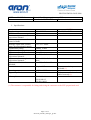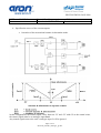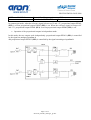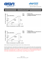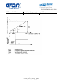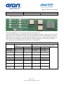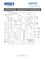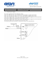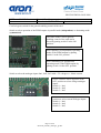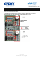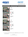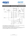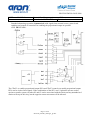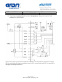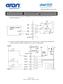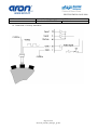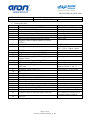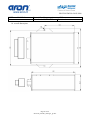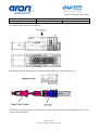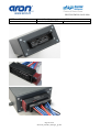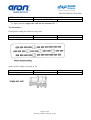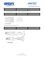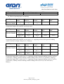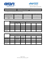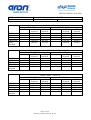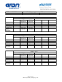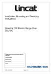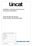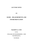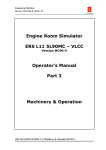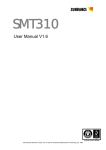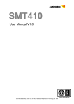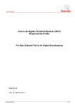
1
REGGIO EMILIA 20/03/2008
USER -
MANUAL
Control Card for pumps/motors - SVP
Manual code :P35160013E
Revision:1
1. Product coding table.
SVP
X
I
E
1
ST
00
D1
Proportional amplifier for control of pumps / motors
X = for 0.88 A proportional Solenoids (24 V DC) (STANDARD)
Y = for 1.76 A proportional Solenoids (12 V DC)
Z = for 2.50 A proportional Solenoids (9 V DC)
I = with independent control of proportional outputs
S = with symmetrical control of proportional outputs (STANDARD)
E = with general enabling control (STANDARD)
K = with general enabling control and consensus for the proportional output
0 = without general enabling control
1 = with ± 5V voltage control signals (STANDARD)
2 = with ± 20mA current control signals
ST = version with panel settings (STANDARD)
CN = version with CAN communication interface (optional)
Versions
00 = no version (STANDARD)
1 series digital model
The product is supplied complete with connector + connector facial sealing gasket + 30 contacts +
30 rubber seals for each wire.
2. Product description.
The SVP electronic current-feedback amplifier is designed to control a variable flow pump or two
pumps on an open circuit, or two motors.
The amplifier has two current-feedback proportional outputs and one power output without current
feedback.
Each proportional output is controlled by an analogue channel. It is, thus, possible to manage the
two proportional outputs independently (the suffix I in the order code stands for independent control
of the proportional outputs).
By selecting a switch on the card, both proportional outputs can be controlled with the same
analogue control input (the suffix S in the order code stands for symmetrical control of the
proportional outputs).
Symmetrical mode is used for pumps on a closed circuit with two-solenoid control. In independent
control mode, the two proportional outputs are independent and two open circuit pumps with single
solenoid control can be controlled WITH EACH OUTPUT. The card also has an output for control
of the brake: this works when the two solenoids have minimum current: the output is disabled as
soon as the current of one of the two solenoids passes the minimum current threshold.
Page 1 of 35
fascicolo_manuali_catalogo1_gb.doc
REGGIO EMILIA 20/03/2008
USER -
MANUAL
Control Card for pumps/motors - SVP
Manual code :P35160013E
Revision:1
3. Key Features
•
•
•
•
•
•
•
•
•
•
The general external control for enabling the card can be activated or bypassed.
Linear and independent, up- and down current ramps on the proportional outputs.
Control of the card via potentiometer, voltage signal (± 5V) from an external source
or current signal from an external source (± 20mA).
Differential analogue control inputs.
Adjustment of the current threshold for intervention of the control output of the
Brake Relais.
Adjustment of the control parameters on the digital panel on the card.
Two digital outputs (0.5A power) for reporting card failure or malfunction
Protection against short circuits on the current outputs.
Protection against polarity inversion on the power supply.
Protection against power supply over voltage.
4. Additional features.
•
•
•
•
When ordering, it is possible to specify the version with general card enabling
control (STANDARD) and separate consensus controls for the activation of the two
proportional outputs (OPTIONAL).
Third analogue input (± 5V or ± 20mA) for acquisition of pressure transducer, or
position transducer (OPTIONAL).
Digital input (12V or 24V) for frequency signals (encoder, or inductive proximity
sensors) (OPTIONAL).
CAN-bus data communication interface (OPTIONAL).
Page 2 of 35
fascicolo_manuali_catalogo1_gb.doc
REGGIO EMILIA 20/03/2008
USER -
MANUAL
Control Card for pumps/motors - SVP
Manual code :P35160013E
Revision:1
5. Specifications.
Supply voltage
Maximum current consumption
Maximum output current for
proportional channel
Maximum output current for
control of brake
Analogue signal from external
source for proportional controls
Potentiometer rating
Adjustment of ramp up time
Adjustment of ramp down time
Adjustment of minimum current of
proportional channels
Adjustment of current gain of
proportional channels
Adjustment of brake release
threshold
Electrical connection
10 ... 30V DC
8A
2.5A
Operating temperature
Degree of protection
-40°C....+80°C
IP65
EC compliance
EN 61000-6-1
EN 61000-6-3
EN ISO 14982
NOTES
Min 9V, Max 36V.
3.0A
± 5V, or ± 20mA
2KΩ to 10 KΩ
0s to 20s
0s to 20s
0 to 50% of selected Imax
50% to 100% of selected
Imax
0 to 50% of selected Imax.
29-pin AMP connector
Connector and crimp contacts
included (*)
With connector fitted and
cabled correctly (*)
(*) The customer is responsible for fitting and wiring the connector to the SVP proportional card.
Page 3 of 35
fascicolo_manuali_catalogo1_gb.doc
REGGIO EMILIA 20/03/2008
USER -
MANUAL
Control Card for pumps/motors - SVP
Manual code :P35160013E
Revision:1
6. Specification curves of the current outputs.
•
Operation of the proportional outputs in alternating mode.
in this configuration, the control signal varies between -5V and +5V with 0V as the central value;
the control signal must be on analogue input Ian 1.
Any control signals sent to the card’s analogue input 2 will be ignored.
Page 4 of 35
fascicolo_manuali_catalogo1_gb.doc
REGGIO EMILIA 20/03/2008
USER -
MANUAL
Control Card for pumps/motors - SVP
Manual code :P35160013E
Revision:1
In symmetrical mode, when the reference signal is between 0V and –5V, proportional output PWM1
(PP1) is off but proportional output PWM2 (PP2) is on. When the reference signal is between 0V
and +5V, proportional output PWM1 (PP1) is on but proportional output PWM2 (PP2) is off.
•
Operation of the proportional outputs in independent mode.
In this mode, the two outputs work independently: proportional output PWM 1 (PP1) is controlled
by the signal on analogue input Ian 1,
and proportional output PWM 2 (PP2) is controlled by the signal on analogue input Ian 2.
Page 5 of 35
fascicolo_manuali_catalogo1_gb.doc
REGGIO EMILIA 20/03/2008
USER -
MANUAL
Control Card for pumps/motors - SVP
Manual code :P35160013E
Revision:1
in this mode, both proportional outputs can be active at the same time.
In both symmetrical or independent operating modes of the proportional outputs, the operating logic
of the control of the brake is always the same. The settings panel is used to set the threshold for the
current (SF), so the brake release output is off when the current on both proportional outputs falls
below the set threshold (SF). It is sufficient for the current of one of the proportional outputs to
exceed the set threshold (SF) for the brake release control output to be activated.
Page 6 of 35
fascicolo_manuali_catalogo1_gb.doc
REGGIO EMILIA 20/03/2008
USER -
MANUAL
Control Card for pumps/motors - SVP
Manual code :P35160013E
Revision:1
Page 7 of 35
fascicolo_manuali_catalogo1_gb.doc
REGGIO EMILIA 20/03/2008
USER -
MANUAL
Control Card for pumps/motors - SVP
Manual code :P35160013E
Revision:1
7. Settings panel on the card
Parameter adjustment is accessed via the panel located on the card.
Press the SELECT button to scroll and select the 9 adjustable parameters in sequence. The lit LED
indicates the selected parameter and the value of the parameter is shown on the display. Use the +
(plus) key to increase the value of the selected parameter; use the – (minus) key to decrease the
value of the selected parameter. Press P1 again to save the setting and access the next parameter.
The settings are saved automatically when the card is switched off.
Table of card parameter settings calibrated for 0.88Ampere Solenoids
Setting range indicated on the Correspondence between the indicated setting
display
range and the controlled physical magnitude
min. setting
max. setting
Minimum
Maximum
PWM1 gain
00
99
00 = 0.50A
99 = 1.0A
PWM1 Imin
00
99
00 = 0.0A
99 = 0.50A
PWM1 ramp 00
99
00 = 0.0 sec
99 = 20 sec
up
PWM1 ramp 00
99
00 = 0.0 sec
99 = 20 sec
dw
PWM2 gain
00
99
00 = 0.50A
99 = 1.0A
PWM2 Imin
00
99
00 = 0.0A
99 = 0.50A
PWM2 ramp 00
99
00 = 0.0 sec
99 = 20 sec
up
PWM2 ramp 00
99
00 = 0.0 sec
99 = 20 sec
dw
Brake
00
99
00 = 0.0A
99 = 0.50A
threshold
Page 8 of 35
fascicolo_manuali_catalogo1_gb.doc
REGGIO EMILIA 20/03/2008
USER -
MANUAL
Control Card for pumps/motors - SVP
Manual code :P35160013E
Revision:1
Table of card parameter settings calibrated for 1.76Ampere Solenoids
Setting range indicated on the Correspondence between the indicated setting
display
range and the controlled physical magnitude
min. setting
max. setting
Minimum
Maximum
PWM1 gain
00
99
00 = 0.90A
99 = 1.8A
PWM1 Imin
00
99
00 = 0.0A
99 = 0.90A
PWM1 ramp 00
99
00 = 0.0 sec
99 = 20 sec
up
PWM1 ramp 00
99
00 = 0.0 sec
99 = 20 sec
dw
PWM2 gain
00
99
00 = 0.90A
99 = 1.8A
PWM2 Imin
00
99
00 = 0.0A
99 = 0.90A
PWM2 ramp 00
99
00 = 0.0 sec
99 = 20 sec
up
PWM2 ramp 00
99
00 = 0.0 sec
99 = 20 sec
dw
Brake
00
99
00 = 0.0A
99 = 0.90A
threshold
Table of card parameter settings calibrated for 2.50Ampere Solenoids
Setting range indicated on the Correspondence between the indicated setting
display
range and the controlled physical magnitude
min. setting
max. setting
Minimum
Maximum
PWM1 gain
00
99
00 = 1.50A
99 = 3.0A
PWM1 Imin
00
99
00 = 0.0A
99 = 1.50A
PWM1 ramp 00
99
00 = 0.0 sec
99 = 20 sec
up
PWM1 ramp 00
99
00 = 0.0 sec
99 = 20 sec
dw
PWM2 gain
00
99
00 = 1.50A
99 = 3.0A
PWM2 Imin
00
99
00 = 0.0A
99 = 1.50A
PWM2 ramp 00
99
00 = 0.0 sec
99 = 20 sec
up
PWM2 ramp 00
99
00 = 0.0 sec
99 = 20 sec
dw
Brake
00
99
00 = 0.0A
99 = 1.50A
threshold
Page 9 of 35
fascicolo_manuali_catalogo1_gb.doc
REGGIO EMILIA 20/03/2008
USER -
MANUAL
Control Card for pumps/motors - SVP
Manual code :P35160013E
Revision:1
8. Block diagram
Page 10 of 35
fascicolo_manuali_catalogo1_gb.doc
REGGIO EMILIA 20/03/2008
USER -
MANUAL
Control Card for pumps/motors - SVP
Manual code :P35160013E
Revision:1
9. General power supply
The card is supplied with V DC continuous voltage.
If the coils connected to the card are 24V DC, the card should be supplied with 24V DC.
If the coils connected to the card are 12V DC, the card should be supplied with 12V DC.
If the card is supplied with 12V DC, the section of the general power supply wires for the card and
for the power supply to the coils should not be less than 1.5mm2.
If the card is supplied with 24V DC, the section of the general power supply wires for the card and
for the power supply to the coils should not be less than 1.0mm2.
The general supply to the card must be protected by means of an external 8A fuse.
Page 11 of 35
fascicolo_manuali_catalogo1_gb.doc
REGGIO EMILIA 20/03/2008
USER -
MANUAL
Control Card for pumps/motors - SVP
Manual code :P35160013E
Revision:1
CenGen bypass switch for the general enabling control of the card.
Switch to select operation of the PWM outputs in parallel mode (independent) or alternating mode
(symmetrical).
The status of the CenGen general
enabling control of the card can be
forced by putting switch 2 in the ON
position.
Select parallel (or independent) operating
mode of the PWM outputs by putting
switch 1 in the ON position.
Select alternating (or symmetrical)
operating mode of the PWM outputs by
putting switch 1 in the OFF position.
Switch to select the analogue inputs Ian1, Ian2, Ian3 with ± 5V voltage or ± 20mA current.
Put the switches shown opposite in the
OFF position to select voltage analogue
inputs.
Switch 1 = Ian1
Switch 2 = Ian2
Switch 3 = Ian3
Put the switches shown opposite in the ON
position to select current analogue inputs.
Switch 1 = Ian1
Switch 2 = Ian2
Switch 3 = Ian3
Page 12 of 35
fascicolo_manuali_catalogo1_gb.doc
REGGIO EMILIA 20/03/2008
USER -
MANUAL
Control Card for pumps/motors - SVP
Manual code :P35160013E
Revision:1
Setting the current on the PWM outputs.
3 different levels of maximum current supplied to the PWM outputs can be set by placing
appropriate solder joints; the current setting is independent for the two exits.
Page 13 of 35
fascicolo_manuali_catalogo1_gb.doc
REGGIO EMILIA 20/03/2008
USER -
MANUAL
Control Card for pumps/motors - SVP
Manual code :P35160013E
Revision:1
10. Connection for standard alternating operation (symmetrical) and general card enabling
(SVP_SE1ST00D1).
Page 14 of 35
fascicolo_manuali_catalogo1_gb.doc
REGGIO EMILIA 20/03/2008
USER -
MANUAL
Control Card for pumps/motors - SVP
Manual code :P35160013E
Revision:1
in this configuration, the control signal varies between –5V and +5V with 0V as the central value;
the control signal must be on analogue input Ian 1.
Any control signals sent to the card’s analogue input Ian 2 will be ignored.
In symmetrical mode, when the reference signal is between 0V and –5V, proportional output PP1 is
off but proportional output PP2 is on. When the reference signal is between 0V and +5V,
proportional output PP1 is on but proportional output PP2 is off.
Page 15 of 35
fascicolo_manuali_catalogo1_gb.doc
REGGIO EMILIA 20/03/2008
USER -
MANUAL
Control Card for pumps/motors - SVP
Manual code :P35160013E
Revision:1
Standard alternating operation (symmetrical) with signal from external source and general card
enabling (SVP_SE1ST00D1).
Page 16 of 35
fascicolo_manuali_catalogo1_gb.doc
REGGIO EMILIA 20/03/2008
USER -
MANUAL
Control Card for pumps/motors - SVP
Manual code :P35160013E
Revision:1
Standard alternating operation (Symmetrical) with signal from external source, general card
enabling and control of consensus for enabling the proportional output in question
(SVP_SK1ST00D1).
The CEnV1 (to enable proportional output PP1) and CEnV2 controls (to enable proportional output
PP2) can be used as limit signals. If the combination of the SPV card + hydraulic unit are used to
operate a transfer system, switches S2 and S3 can be associated with the limits and any unauthorised
motion will stop in this way, but the opposite return movement will be allowed.
Page 17 of 35
fascicolo_manuali_catalogo1_gb.doc
REGGIO EMILIA 20/03/2008
USER -
MANUAL
Control Card for pumps/motors - SVP
Manual code :P35160013E
Revision:1
11. Connection for standard parallel operation (Independent) and general control of card
enabling (SVP_IE1ST00D1).
In this mode, the two proportional outputs PP1 and PP2 work independently. Proportional output
PP1 is controlled by the signal on analogue input Ian PP1; proportional output PP2 is controlled by
the signal on analogue input Ian 2.
Page 18 of 35
fascicolo_manuali_catalogo1_gb.doc
REGGIO EMILIA 20/03/2008
USER -
MANUAL
Control Card for pumps/motors - SVP
Manual code :P35160013E
Revision:1
Standard parallel operation (Independent) with signal from external source (SVP_IE1ST00D1) and
general control of card enabling.
Page 19 of 35
fascicolo_manuali_catalogo1_gb.doc
REGGIO EMILIA 20/03/2008
USER -
MANUAL
Control Card for pumps/motors - SVP
Manual code :P35160013E
Revision:1
Standard parallel operation (Independent) with signal from external source, general card enabling
and control of consensus for enabling the proportional output in question (SVP_IK1ST00D1).
The CEnV1 (to enable proportional output PP1) and CEnV2 controls (to enable proportional output
PP2) can be used as limit signals. If the combination of the SPV card + hydraulic unit are used to
operate a transfer system, switches S2 and S3 can be associated with the limits and any unauthorised
motion will stop in this way, but the opposite return movement will be allowed.
Page 20 of 35
fascicolo_manuali_catalogo1_gb.doc
REGGIO EMILIA 20/03/2008
USER -
MANUAL
Control Card for pumps/motors - SVP
Manual code :P35160013E
Revision:1
12. Connecting the proportional Solenoids and the brake control Solenoid.
the return of the proportional Solenoids and the brake control Solenoid must be connected directly
to the battery negative or the general power source.
CAUTION: a bad connection to the battery negative or the use of a wire whose section is too small
does not allow for the proper setting of the proportional current to the Solenoids.
For proportional Solenoids with 1.8A current, use wire whose section is no less than 1.5mm2. For
proportional Solenoids with 0.9A current, use wire whose sections is no less than 1.0mm2.
The wire for connecting the brake control Solenoid must have a section of no less than 1.5mm2.
Page 21 of 35
fascicolo_manuali_catalogo1_gb.doc
REGGIO EMILIA 20/03/2008
USER -
MANUAL
Control Card for pumps/motors - SVP
Manual code :P35160013E
Revision:1
13. Connecting the signal or alarm digital outputs.
-------------------------------------------------------------------------------------------------------------------
Page 22 of 35
fascicolo_manuali_catalogo1_gb.doc
REGGIO EMILIA 20/03/2008
USER -
MANUAL
Control Card for pumps/motors - SVP
Manual code :P35160013E
Revision:1
14. connection of third analogue input Ian3 for general external signals, from position or
pressure transducers.
15. connection of general digital controls Cgen1 and Cgen2, for example from external limit
switches, pressure switches, minimum level sensors or thermostats.
Page 23 of 35
fascicolo_manuali_catalogo1_gb.doc
REGGIO EMILIA 20/03/2008
USER -
MANUAL
Control Card for pumps/motors - SVP
Manual code :P35160013E
Revision:1
16. Connection of velocity transducer.
Page 24 of 35
fascicolo_manuali_catalogo1_gb.doc
REGGIO EMILIA 20/03/2008
USER -
MANUAL
Control Card for pumps/motors - SVP
Manual code :P35160013E
Revision:1
17. Connections table
Contact n.
Function
1
General power supply + BATTERY
2
Proportional output 2 (PP2)
3
Proportional output 1 (PP1)
4
On/off signal output (O/F 2)
5
Input for enabling PP1 (CEnV1)
6
Input for general digital control 2 (Cgen2)
7
Negative return for digital signal revs sensor
(CENC-)
8
Analogue control input 3 (Ian 3)
9
Analogue control input 1 (Ian 1)
10
11
12
13
17
18
19
20
21
22
23
24
25
26
27
28
CAN_L
0V general power supply - BATTERY
0V general power supply – BATTERY
Common power supply (O/F23) digital signal
outputs 2 and 3
Input for general card enabling (CEnGen)
Input for enabling PP2 (CenV2)
Negative return of digital controls and enabling
(DinCom)
Regulated output voltage +5V
0V
CAN_gnd
0V
On/off current output (O/F1) 3A brake control
On/off signal output (O/F 3)
0V
Input for general digital control 1 (Cgen1)
positive input for digital signal revs sensor (CENC)
Regulated output voltage -5V
Analogue control input 2 (Ian 2)
Common return of analogue inputs (IanCom)
29
CAN_H
14
15
16
Page 25 of 35
fascicolo_manuali_catalogo1_gb.doc
Notes
Min 10Vdc, max 30Vdc
See diagram in section 12
See diagram in section 12
Max current 0.5A
Active high
Active high
0..5V or 0..20mA
0..5V or 0..20mA /
-5V...+5V or –20mA...20mA
See diagram in section 13
Active high
Active high
See examples of connection in
sections 10 and 11 and 15
Potentiometer power supply
See diagram in section 12
Max current 0.5A
Active high
Potentiometer power supply
0..5V or 0..20mA
See examples of connection in
sections. 10 and 11 and 14
REGGIO EMILIA 20/03/2008
USER -
MANUAL
Control Card for pumps/motors - SVP
Manual code :P35160013E
Revision:1
18. overall dimensions
Page 26 of 35
fascicolo_manuali_catalogo1_gb.doc
REGGIO EMILIA 20/03/2008
USER -
MANUAL
Control Card for pumps/motors - SVP
Manual code :P35160013E
Revision:1
29-contact AMP connector, wiring side.
Detail of how to crimp the electrical contact and the rubber seal on the electric wire.
CAUTION: Any pins which are not connected on the wired side must be sealed with the cavity seals
(red), ordered separately.
Page 27 of 35
fascicolo_manuali_catalogo1_gb.doc
REGGIO EMILIA 20/03/2008
USER -
MANUAL
Control Card for pumps/motors - SVP
Manual code :P35160013E
Revision:1
Page 28 of 35
fascicolo_manuali_catalogo1_gb.doc
REGGIO EMILIA 20/03/2008
USER -
MANUAL
Control Card for pumps/motors - SVP
Manual code :P35160013E
Revision:1
19. Spare parts kit (single order code for the customer VE -)
The kit includes:
Facial gasket sealing for connector (one piece)
Facial Sealing
Aron code
VE ----
AMP code
963222-1
Gasket seal for single wire (pack of 30)
Wire sealing
Aron code
VE0010400
Page 29 of 35
fascicolo_manuali_catalogo1_gb.doc
AMP code
828905_1
REGGIO EMILIA 20/03/2008
USER -
MANUAL
Control Card for pumps/motors - SVP
Manual code :P35160013E
Revision:1
Gasket to seal unused contact on loose connector, wiring side (pack of 15).
Cavity sealing
Aron code
VE -----
AMP code
828906
Junior power timer contact (pack of 30).
JPT crimp contact
Aron code
VE0020600
Page 30 of 35
fascicolo_manuali_catalogo1_gb.doc
AMP code
929937-3 or 929938-3
REGGIO EMILIA 20/03/2008
USER -
MANUAL
Control Card for pumps/motors - SVP
Manual code :P35160013E
Revision:1
Loose side of connector (pack of 1).
Plug connector 29 pin
Aron code
VE
Page 31 of 35
fascicolo_manuali_catalogo1_gb.doc
AMP code
963449-2
REGGIO EMILIA 20/03/2008
USER -
MANUAL
Control Card for pumps/motors - SVP
Manual code :P35160013E
Revision:1
20. Table of operating logic for enabling.
Card Type
CenGen
Status
SVP**0*ST00D1
Any X
SVP**0*CN00D1
→
Status
CEnV1
Any X
→
Status
CEnV2
Any X
→
Output
PP1
Active
Output
PP2
Active
Status
CEnV2
Any X
→
Any X
→
Output
PP1
Inactive
Output
PP2
Inactive
Active
Active
Proportional outputs PP1 and PP2 are always active.
Card Type
CenGen
Status
SVP**E*ST00D1
Level 0V
SVP**E*CN00D1
LO →
+ Batt level
HI →
Status
CEnV1
Any X
→
Any X
→
Proportional outputs PP1 and PP2 are only active (i.e. supplying current) if the general enabling
control CenGen is at high voltage level (+ Battery).
Card Type
CenGen
Status
SVP**K*ST00D1
Level 0V
SVP**K*CN00D1
LO →
+ Batt level
HI →
+ Batt level
HI →
Status
CEnV1
Any X
→
Level 0V
LO →
+ Batt level
HI →
Status
CEnV2
Any X
→
Level 0V
LO →
+ Batt level
HI →
Output
PP1
Inactive
Output
PP2
Inactive
Inactive
Inactive
Active
Active
Proportional output PP1 is only active (i.e. supplying current) if general enabling control (CenGen)
is activated (+ Battery) and the enabling control relating to PP1 (CEnV1) is activated (+ Battery).
Proportional output PP2 is only active (i.e. supplying current) if general enabling control (CenGen)
is activated (+ Battery) and the enabling control relating to PP2 (CEnV2) is also activated (+
Battery).
Page 32 of 35
fascicolo_manuali_catalogo1_gb.doc
REGGIO EMILIA 20/03/2008
USER -
MANUAL
Control Card for pumps/motors - SVP
Manual code :P35160013E
Revision:1
21. Table of recommended parameters settings
Control with Solenoid
Product code for
matching SVP card
Recommended card
supply
9V (special request)
SVPZ***ST00D1
12V standard
SVPY***ST00D1
24V standard
SVPX***ST00D1
12VDC
12VDC
24VDC
Model : H1V
PWM1 Imin
PWM2 Imin
PWM1 Gain
PWM2 Gain
Brake
threshold
With EM Control
12V
Solenoid
650 mA
650 mA
1400 mA
1400 mA
650 mA
24V
Solenoid
350 mA
350 mA
700 mA
700 mA
350 mA
Model : H2V
PWM1 Imin
PWM2 Imin
PWM1 gain
PWM2 gain
Brake
threshold
With EM Control
12V
Solenoid
650 mA
650 mA
1400 mA
1400 mA
650 mA
24V
Solenoid
350 mA
350 mA
700 mA
700 mA
350 mA
Page 33 of 35
fascicolo_manuali_catalogo1_gb.doc
REGGIO EMILIA 20/03/2008
USER -
MANUAL
Control Card for pumps/motors - SVP
Manual code :P35160013E
Revision:1
Model : HCV
PWM1 Imin
PWM2 Imin
PWM1 gain
PWM2 gain
Brake
threshold
PWM1 Imin
PWM2 Imin
PWM1 gain
PWM2 gain
Brake
threshold
PWM1 Imin
PWM2 Imin
PWM1 gain
PWM2 gain
Brake
threshold
With HE Control
12V
Solenoid
600 mA
600 mA
1500 mA
1500 mA
600 mA
24V
Solenoid
300 mA
300 mA
800 mA
800 mA
300 mA
With HE + HI Control
12V
24V
Solenoid
Solenoid
600 mA
300 mA
600 mA
300 mA
1500 mA
800 mA
1500 mA
800 mA
600 mA
300 mA
Model : SH6V 55 and 100
With HER / HEH Control
With HEN Control
12V
24V
12V
24V
Solenoid
Solenoid
Solenoid
Solenoid
400 mA
200 mA
600 mA
300 mA
400 mA
200 mA
600 mA
300 mA
1000 mA
500 mA
1100 mA
600 mA
1000 mA
500 mA
1100 mA
600 mA
400 mA
200 mA
600 mA
300 mA
Model : SH6V 75 and 130
With HER / HEH Control
With HEN Control
12V
24V
12V
24V
Solenoid
Solenoid
Solenoid
Solenoid
400 mA
200 mA
600 mA
300 mA
400 mA
200 mA
600 mA
300 mA
1200 mA
600 mA
1300 mA
700 mA
1200 mA
600 mA
1300 mA
700 mA
400 mA
200 mA
600 mA
300 mA
Page 34 of 35
fascicolo_manuali_catalogo1_gb.doc
REGGIO EMILIA 20/03/2008
USER -
MANUAL
Control Card for pumps/motors - SVP
Manual code :P35160013E
Revision:1
Model : MD10V 21/28
PWM1 Imin
PWM2 Imin
PWM1 gain
PWM2 gain
Brake
threshold
PWM1 Imin
PWM2 Imin
PWM1 gain
PWM2 gain
Brake
threshold
With HER Control
12V
24V
Solenoid
Solenoid
400 mA
200 mA
400 mA
200 mA
1000 mA
500 mA
1000 mA
500 mA
400 mA
200 mA
Model : MD10V 50/64
With HER Control
12V
24V
Solenoid
Solenoid
400 mA
200 mA
400 mA
200 mA
1100 mA
550 mA
1100 mA
550 mA
400 mA
200 mA
Model : SH7V
PWM1 Imin
PWM2 Imin
PWM1 gain
PWM2 gain
Brake
threshold
With REN Control
12V
24V
Solenoid
Solenoid
400 mA
200 mA
400 mA
200 mA
1200 mA
600 mA
1200 mA
600 mA
400 mA
200 mA
Page 35 of 35
fascicolo_manuali_catalogo1_gb.doc