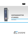
1
_EN_ VIBTRANSMITTER VT1002DS USER MANUAL VIBTRANSMITTER VT1002DS TABLE OF CONTENTS I. Introduction ........................................................................................................................ 4 II. General information ........................................................................................................... 5 III. Module description............................................................................................................. 6 IV. Front panel description ...................................................................................................... 7 IV.1. Measurement chain diagnostics for IEPE sensor ........................................................ 7 IV.2. Alarm outputs and proper work indicators ................................................................. 7 IV.3. Keyboard and measured value indicators ................................................................... 8 V. Installation and usage ......................................................................................................... 8 V.1. Mounting ..................................................................................................................... 8 V.2. Galvanic isolation ........................................................................................................ 9 V.3. Electrical connectors ................................................................................................... 9 V.4. AC Voltage output ..................................................................................................... 10 V.5. Activation................................................................................................................... 10 VI. Operation of the module .................................................................................................. 11 VI.1. Alarming system ........................................................................................................ 12 VII. Configuration of the VT1002DS ........................................................................................ 14 VII.1. Entering the menu ..................................................................................................... 14 VII.2. Setting up of the warning threshold – ‘U’................................................................. 15 VII.3. Setting up of the warning threshold – ‘A’ ................................................................. 15 VII.4. Signaling of the sensor failure – ‘CU’, ‘CA’ .............................................................. 16 VII.5. Signaling of the measurement conditions – ‘FU’, ‘FA’ ............................................ 16 VII.6. Setting up of the delay threshold – ‘d’ ...................................................................... 16 VII.7. Setting up the latch of alarm threshold or warning threshold violation – ‘L’ .......... 17 VII.8. Setting up the safety factors for warning and alarm thresholds – ‘Ur’, ‘Ar’ ............ 17 VII.9. Setting up the correction of values indicated by the module – ‘SC’ ....................... 18 VII.10. Setting up alarm system activation delay after the machine’s start-up – ‘Uo’ ........ 18 VII.11. Setting up analysis type and measurement conditions – ‘UU’................................. 18 VII.12. Turning off display on sensor failure – ‘Er’ ............................................................... 19 VII.13. Selecting the measured vibration signal estimate – ‘AU’......................................... 19 VII.14. Performing copy/delete operations for the whole alarming system – ‘OA’ ............ 20 VII.15. Browsing maximal registered values in the reference period – ‘uL’ ........................ 21 VII.16. Setting the displayed and transmitted over 4-20 mA output value – ‘uu’ ............... 21 VII.17. Measurement parameter configuration ................................................................... 22 VIII. Menu ................................................................................................................................. 24 IX. Technical parameters ....................................................................................................... 27 EC SYSTEMS –2– USER MANUAL _EN_ LIST OF FIGURES Figure 1 » VT1002DS dimension ................................................................................................. 6 Figure 2 » Exemplary installation of 3 VT1002DS modules on a DIN rail ................................... 8 Figure 3 » VT1002DS isolation .................................................................................................... 9 Figure 4 » VT1002DS connectors................................................................................................ 9 Figure 5 » VT1002DS current loop............................................................................................ 10 Figure 6 » VT1002DS AC voltage output .................................................................................. 10 Figure 7 » Graph showing all available analysis when using the option to calculate the values in angular intervals ................................................................................................................... 12 Figure 8 » Functions of configuration switches ........................................................................ 23 –3– EC SYSTEMS VIBTRANSMITTER VT1002DS I. INTRODUCTION The following paragraph does not apply to countries where legal provisions do not comply to the conditions and terms described herein. EC SYSTEMS DOES NOT TAKE ANY LIABILITY CONCERNING THIS MANUAL, WHETHER EXPLICIT NOR IMPLIED (BUT NOT LIMITED TO); NOR CONCERNING A TYPICAL AVERAGE MARKET QUALITY OR THE FITNESS FOR ANY SPECIAL PURPOSE. In some countries and parts of some countries the exclusion and/or limitation of the duration of explicit or implied warranties concerning certain transactions are not allowed. Therefore the declaration above may be not effective in certain areas. This publication may contain erroneous information and/or typographic errors. The contained information is revised in an on-going process. So later editions can contain changes. Products/software described herein may be changed and improved at any time without any obligation to a prior announcement. Any product and company names mentioned herein may be protected trademarks. © COPYRIGHT The following document is the property of EC Systems, which reserves all the copyrights, patent-pending law and templates included. Copying or other abuse of this document or its parts, or sharing with third parties requires the written permission of EC Systems. EC SYSTEMS –4– USER MANUAL _EN_ II. GENERAL INFORMATION VIBTransmitter VT1002DS is a universal module for condition monitoring of reciprocating compressors. The features of VT1002DS are as follow: ICP® (IEPE) standard accelerometer input, 4..20 mA output proportional to signal estimate, vibration velocity or acceleration measurement, calculation of RMS or PEAK values, measurement of the selected estimate in angular intervals (24 values per one revolution) configurable warning and alarm relay outputs, together with the delay of the output, automatic warning and alarm threshold setting based on reference measurement period built-in connector for the AC voltage signal from the vibration sensor (10 Vpp), DIN rail mounting. The system is a perfect solution for automated protection systems of rotating machines. The device can be integrated with the controller via the 4..20 mA current output. The 10 Vpp AC voltage output allows to control the vibration level using a portable vibration analyzer. In addition, the relay outputs can be used as safety features. If alarm level is exceeded VT1002DS module can turn off the unit before critical damage occurs. –5– EC SYSTEMS VIBTRANSMITTER VT1002DS III. MODULE DESCRIPTION Figure 1 » VT1002DS dimension The functionalities of the connectors indicated on the Figure 1 are as follow: 1. IEPE sensor circuit signalisation: open – open-circuit or sensor failure short – short-circuit or sensor failure 2. Signal estimate signalisation – one can choose form RMS or PEAK values; the choice is indicated by appropriate diode 3. Measured value signalisation – one can choose form velocity or acceleration 4. Presentation of the outputs states 5. Keyboard 6. 2-digit LED display 7. Power connector and sensor input 8. 4..20 mA current loop and relay-outputs connector 9. Set of configurable switches (SW2) 10. Set of configurable switches (SW1) 11. SMB connector for voltage vibration output signal EC SYSTEMS –6– USER MANUAL _EN_ IV. FRONT PANEL DESCRIPTION IV.1. MEASUREMENT CHAIN DIAGNOSTICS FOR IEPE SENSOR Red LEDs – indicator of the sensor status: open – open circuit or sensor failure short – short circuit or sensor failure Green LEDs: indicator of the selected estimate: o RMS – RMS value of vibration signal o PEAK – maximum value of vibration signal (0-Peak) indicator of the selected measured value: o acc – acceleration o vel – velocity IV.2. ALARM OUTPUTS AND PROPER WORK INDICATORS Alarm outputs indicators: red LED – ALARM – the alarm threshold exceeded, alarm output ON yellow LED – WARNING – the warning threshold exceeded, warning ON green LED – OK – proper work indicator: o diode pulsing with frequency of 1 Hz indicates the correct operation of the device o rapid pulsing means entering the device setup menu –7– EC SYSTEMS VIBTRANSMITTER VT1002DS IV.3. KEYBOARD AND MEASURED VALUE INDICATORS Keyboard: UP – up DN – down SET – set Measured value – double-digit LED display V. INSTALLATION AND USA GE V.1. MOUNTING VIBTransmitter VT1002DS module is designed for mounting on 35mm DIN rail in an upright position. Figure 2 presents the 3 VT1002DS modules mounted on a DIN rail. Figure 2 » Exemplary installation of 3 VT1002DS modules on a DIN rail EC SYSTEMS –8– USER MANUAL _EN_ V.2. GALVANIC ISOLATION VIBTransmitter VT1002DS guarantees full galvanic isolation between power supply of the module with the sensor, warning / alarm outputs and the current loop in the case of external supply of the 4..20 mA current loop. Figure 3 presents the schematic block of above mentioned isolation. Figure 3 » VT1002DS isolation V.3. ELECTRICAL CONNECTORS Description of the connectors is presented on the Figure 4. Figure 4 » VT1002DS connectors –9– EC SYSTEMS VIBTRANSMITTER VT1002DS 4..20 mA current connection is shown on the Figure 5. Figure 5 » VT1002DS current loop V.4. AC VOLTAGE OUTPUT The usage of the voltage output of the module should be performed according to Figure 6. Figure 6 » VT1002DS AC voltage output V.5. ACTIVATION After connecting the power, the VT1002DS module enters into testing procedure. Subsequently all LEDs will flash for a short period of time. If everything is operating properly, then LED is pulsing with a frequency of approximately 1 Hz. Once the testing procedure is over, the device is ready to operate. If an error of a sensor circuit is detected, then corresponding LED will lit. EC SYSTEMS – 10 – USER MANUAL _EN_ VI. OPERATION OF THE MOD ULE The module can perform the following analysis of vibration velocity or acceleration: RMS value calculation for one full revolution RMS value calculation in 15 degree angular intervals (24 intervals per one full revolution) RMS value calculation for one second measurement buffer 0-PEAK value calculation for one full revolution 0-PEAK value calculation in 15 degree angular intervals (24 intervals per one full revolution) 0-PEAK value calculation for one second measurement buffer The type of performed analysis depends on the module’s configuration. When signal estimate value is being calculated in angular intervals, at the same time the value is being calculated for the full revolution, but not for one second measurement buffer. When signal estimate value is being calculated for one second measurement buffer, it is not calculated in angular intervals. The type of performed analysis can be selected together with defining measurement conditions (‘UU’ option), configuring measured value (‘AU’ option), and selecting displayed and transmitted through 4-20 mA output value (‘uu’ option). When selected displayed and transmitted value is different from the measured value, the module displays ‘0.0’ value, even though the connected sensor is being excited. In such cases selected combination of ‘UU’ and ‘uu’ options needs to be checked. When performing measurements, which use the phase marker input (for full revolution and for angular intervals), two requirements need to be fulfilled: rotational speed in the range between 1 and 20 revolutions per second stable level of the rotational speed: it cannot change more than 10% for 3 consecutive revolution The graph below shows all available analysis, which can be performed by the module, when using the option to calculate the values in angular intervals. The module is able to display and transmit through the 4-20 mA output just one value, selected using the ‘uu’ option in the menu. – 11 – EC SYSTEMS VIBTRANSMITTER VT1002DS Figure 7 » Graph showing all available analysis when using the option to calculate the values in angular intervals VI.1. ALARMING SYSTEM The module features an advanced alarming system. For each of the calculated values it is possible to set up two thresholds: WARNING – information to the machine’s operator about elevated vibration level ALARM – critical level of vibration causing an emergency shutdown of the machine All the thresholds can be set up manually and automatically. The manual set up can be done using the ‘uu’, ‘U’ and ‘A’ options in the menu. The in the ‘uu’ option it is possible to select the value for which the threshold is to be set up, the selection being: one of the 24, 15 degree angular intervals, the maximal value from 24, 15 degree angular intervals, value for the full revolution and for one second measurement buffer. Once the value is selected, the ‘U’ option can be used to set up the warning threshold, while the ‘A’ option to set up the alarm threshold. It is also possible to set up these thresholds automatically using the feature to store the maximal values registered during the module’s operation (note: turning off the module deletes the memory). To use this feature properly it is necessary to monitor the operating machine in conditions which will include special, but not critical events, like switch-overs and temporary overload. The more special events are registered, the higher is the certainty, that the machine is not going to be turned off by a false alarm in the future. EC SYSTEMS – 12 – USER MANUAL _EN_ The reference period should be relatively short, usually it is one day long, assuming, that the machine has been operating in all the possible special conditions. The maximal recommended length of the reference period is around one week. The maximal registered values can be browsed using the ‘uL’ option. To set up the thresholds it is necessary define the safety factor in the ‘Ur’ option for the warning threshold, and ‘Ar’ for alarm. Usually the ‘Ur’ factor is at 1.5 level, while ‘Ar’ at 2. The automatic set up of the thresholds can be done in the ‘OA’ option by selecting the ‘SU’ and ‘SA’ options. In case when the product of the maximal registered value and the safety factor exceeds the measurement range, the thresholds is disabled. For this reason it is recommended to browse the maximal values before enabling the automatic threshold setting, to avoid disabling some thresholds by accident. The alarming system includes indication of sensor failures. The ‘CU’ and ‘CA’ options allow enabling warning and alarm when a sensor failure is detected. The ‘FU’ and ‘FA’ options allow enabling warning and alarm when measurement conditions set in the ‘UU’ option are not fulfilled. It is not recommended to enable the ‘FA’ option, as it will activate the shutdown alarm, when the machine is turned off, due to the missing phase marker signal. This can make it impossible to turn the machine on again. In the alarming system it is possible to define two kinds of delays. One of them is alarm system activation delay after the machine’s start-up (the ‘Uo’ option), while the other is alarm activation delay after breaching of one of the thresholds (the ‘d’ option). As the machine’s start-up the module interprets the following events: turning on the power, registration of cyclical changes on phase marker input with frequency in the range from 1Hz to 20Hz, or the elevated state on phase marker input (logical state from supervisory system). The interpretation type depends on the ‘UU’ option. In case of the elevated state on phase marker input the operation synchronized with shaft revolutions is not possible, due to the fact, that the phase marker input is used as input from the supervisory system. The maximal range of the start-up delay is 90 minutes. The alarm activation delay is defined for all the thresholds in the ‘d’ option, however the delay time runs for each threshold individually. This means, that the alarm is activated only when a particular value stays above the threshold beyond the time defined in the ‘d’ option. The module can record information about the alarms. The ‘L’ option allows configuration of the system’s behaviour once a threshold is no longer breached. The available options are the following: No recording of the alarms - once a threshold is no longer breached the module operates as if nothing has happened. Indication though diodes on the front panel - once a threshold is no longer breached the relay outputs return to the normal state. The diodes on the front panel remain activated until the user acknowledges by pressing the ‘SET’ button on the front panel. – 13 – EC SYSTEMS VIBTRANSMITTER VT1002DS Indication though relay outputs and diodes on the front panel - once a threshold is no longer breached the relay outputs and diodes on the front panel remain activated until the user acknowledges by pressing the ‘SET’ button on the front panel. The ‘OA’ option is also related to the alarm system. It can be used to: Copy defined warning or alarm threshold to all the other values Delete all warning or alarm thresholds Define all warning or alarm thresholds based on the maximal reference values Delete all the recorded maximal reference values VII. CONFIGURATION OF THE VT1002DS The front panel of the VT1002DS module contains three buttons, labeled subsequently UP, DN and SET. These buttons are used to edit the module functions. VII.1. ENTERING THE MENU During normal operation of the VT1002DS module, pressing UP or DN button will cause entering into the device menu, which is indicated by rapid blinking of the OK LED. While in edit mode, buttons UP/DN scroll the menu items: U – warning, A – alarm, CU – warning activation in case of the sensor circuit failure, CA – alarm activation in case of the sensor circuit failure, FU - warning activation when measurement conditions are not fulfilled, FA - alarm activation when measurement conditions are not fulfilled, d – thresholds activation delay, L – latching of alarm threshold or warning threshold violation, Ur – safety factor for warning thresholds, Ar- safety factor for alarm thresholds, SC – correction of values indicated by the module, Uo - alarm system activation delay after the machine’s start-up, UU – analysis type and measurement conditions set up, Er – turning display off on sensor failure, AU – selection of vibration signal estimate, OA – copy/delete operations for the whole alarming system, uL – maximal values registered in the reference period, uu – value displayed on the front panel and transmitted over 4-20 mA output. EC SYSTEMS – 14 – USER MANUAL _EN_ VII.2. SETTING UP OF THE WARNING THRESHOLD – ‘U’ The VT1002DS module has a two level alarming system. The ‘U’ is by default the lower level. It should be used for notification about elevated vibration level, but not for emergency shutdown of the machine. The threshold can be set up for all the 27 values measured by the module. To set the warning threshold one should perform the following procedure: 1. Press UP/DN. Afterwards the OK LED will blink rapidly, which indicates entering into the device menu. 2. By pressing UP/DN set the ‘uu’ letters on the display. 3. Confirm by pressing the SET button. 4. By pressing UP/DN set the value for which you wish to define the threshold. 5. Confirm by pressing the SET button. If the module is operating, the display will show the current level of the value. 6. Press UP/DN. Afterwards the OK LED will blink rapidly, which indicates entering into the device menu. 7. By pressing UP/DN set the ‘U’ letter on the display. 8. Use the UP/DN buttons to select the desired warning threshold value in the range from 0.0 to 99 or the ‘oF’ to disable the warning threshold. 9. Confirm by pressing the SET button. 10. If the signal exceeds the threshold value over time beyond the defined delay time (the ‘d’ option) the WARNING relay will be activated. VII.3. SETTING UP OF THE WARNING THRESHOLD – ‘A’ The VT1002DS module has a two level alarming system. The ‘A’ is by default the higher level. It can be used for notification about elevated vibration level, and for emergency shutdown of the machine. The threshold can be set up for all the 27 values measured by the module. To set the warning threshold one should perform the following procedure: 1. Press UP/DN. Afterwards the OK LED will blink rapidly, which indicates entering into the device menu. 2. By pressing UP/DN set the ‘uu’ letters on the display. 3. Confirm by pressing the SET button. 4. By pressing UP/DN set the value for which you wish to define the threshold. 5. Confirm by pressing the SET button. If the module is operating, the display will show the current level of the value. 6. Press UP/DN. Afterwards the OK LED will blink rapidly, which indicates entering into the device menu. 7. By pressing UP/DN set the ‘A’ letter on the display. 8. Use the UP/DN buttons to select the desired alarm threshold value in the range from ‘0.0’ to ‘99’ or the ‘oF’ to disable the alarm threshold. 9. Confirm by pressing the SET button. – 15 – EC SYSTEMS VIBTRANSMITTER VT1002DS 10. If the signal exceeds the threshold value over time beyond the defined delay time (the ‘d’ option) the ALARM relay will be activated. VII.4. SIGNALING OF THE SENSOR FAILURE – ‘CU’, ‘CA’ For full control of the measurement chain VT1002DS can trigger warning or alarm when the measurement chain or vibration sensor is damaged. It occurs after the delay time defined in the ‘d’ option. To set up the sensor failure signaling on the warning or alarm output one should perform the following procedure: 1. Press UP/DN. Afterwards the OK LED will blink rapidly, which indicates entering into the device menu. 2. By pressing UP/DN set the ‘CU’ (for warning) or ‘CA’ (for alarm) on the display. 3. Confirm by pressing the SET button. 4. Use the UP/DN buttons to select the ‘on’ or ‘oF’ option. 5. To confirm the change, press the SET button. VII.5. SIGNALING OF THE MEASUREMENT CONDITIONS – ‘FU’, ‘FA’ The option allows to trigger warning or alarm when the measurement conditions set in the ‘UU’ option are not fulfilled. It occurs after the delay time defined in the ‘d’ option. To set up the sensor failure signaling on the warning or alarm output one should perform the following procedure: 1. Press UP/DN. Afterwards the OK LED will blink rapidly, which indicates entering into the device menu. 2. By pressing UP/DN set the ‘FU’ (for warning) or ‘FA’ (for alarm) on the display. 3. Confirm by pressing the SET button. 4. Use the UP/DN buttons to select the ‘on’ or ‘oF’ option. 5. To confirm the change, press the SET button. VII.6. SETTING UP OF THE DELAY THRESHOLD – ‘d’ In the VT1002DS module the user can define how long the alarm threshold or the warning threshold should exceeded before activating the relay output. To set the delay one should perform the following procedure: 1. Press UP/DN. Afterwards the OK LED will blink rapidly, which indicates entering into the device menu. 2. By pressing UP/DN set the letter ‘d’ on the display. 3. Confirm by pressing the SET button. 4. Use the UP/DN buttons to select the desired delay time in the range from ‘0’ to ‘16’ s. 5. To confirm the change, press the SET button. EC SYSTEMS – 16 – USER MANUAL _EN_ VII.7. SETTING UP THE LATCH OF ALARM THRESHOLD OR WARNING THRESHOLD VIOLATION – ‘L’ VIBTransmitter VT1002DS has the ability to store the information about the violation of the warning or the alarm threshold. When the violation occurs, after the delay ‘d’, proper relay output and LED on the front panel is activated until the user erases the violation information by pressing the SET button. To set up the latch one should perform the following procedure: 1. Press UP/DN. Afterwards the OK LED will blink rapidly, which indicates entering into the device menu. 2. By pressing UP/DN set the letter ‘L’ on the display. 3. Confirm by pressing the SET button. 4. Use the UP/DN buttons to select one of the available options: ‘oF’ - once the triggering condition (e.g. breached threshold, sensor failure, etc.) is no longer present the module operates as if nothing has happened. The LED signalization on the front panel and triggering relay outputs is active only when the triggering condition is fulfilled. a. ‘_L’ - once the triggering condition is no longer present the relay outputs return to the normal state. The diodes on the front panel remain activated until the user acknowledges by pressing the ‘SET’ button on the front panel. The recorded alarms or warnings can be viewed using the ‘uu’ option. b. ‘PL’ - once the triggering condition is no longer present the relay outputs and the diodes on the front panel remain activated until the user acknowledges by pressing the ‘SET’ button on the front panel. The recorded alarms or warnings can be viewed using the ‘uu’ option. 5. To confirm the change, press the SET button. VII.8. SETTING UP THE SAFETY FACTORS FOR WARNING AND ALARM THRESHOLDS – ‘Ur’, ‘Ar’ The safety factors are parameters indicating numbers by which maximal recorded values from the reference period should be multiplied to achieve warning and alarm thresholds in the automatic set up mode. To set up the safety factors one should perform the following procedure: 1. Press UP/DN. Afterwards the OK LED will blink rapidly, which indicates entering into the device menu. 2. By pressing UP/DN set the ‘Ur’ (for warning) or ‘Ar’ (for alarm) on the display. 3. Confirm by pressing the SET button. 4. Use the UP/DN buttons to select the value in the range from ‘0’ to ‘9.9’ 5. To confirm the change, press the SET button. – 17 – EC SYSTEMS VIBTRANSMITTER VT1002DS VII.9. SETTING UP THE CORRECTION OF VALUES INDICATED BY THE MODULE – ‘SC’ The VT1002DS module is designed to work with ICP® (IEPE) accelerometers with sensitivity of 100 mV/g, however it is possible to set up set correction of values indicated by the module to adjust the module to a sensor with sensitivity different than 100 mV/g. The ‘SC’ parameter indicates how much the presented values are being increased or decreased. To set correction of values indicated by the module one should perform the following procedure: 1. Press UP/DN. Afterwards the OK LED will blink rapidly, which indicates entering into the device menu. 2. By pressing UP/DN set the ‘SC’ on the display. 3. Confirm by pressing the SET button. 4. Use the UP/DN buttons to select the desired correction value. Negative values are indicated by glowing decimal point in the bottom right of the display: a. ‘0’ to ‘9.9’ – means increasing of the measured value by selected percentage b. ‘0’ to ‘9.9.’ – means decreasing of the measured value by selected percentage 5. To confirm the change, press the SET button. VII.10. SETTING UP ALARM SYSTEM ACTIVATION DELAY AFTER THE MACHINE’S START-UP – ‘Uo’ This feature allows delaying the activation of the alarm system after the machine start-up. Under normal circumstances it is not recommended to use this feature, however there are several situations when this feature is indispensable. The machine’s start-up can be indicated by turning on the module or fulfilling the measurement conditions set up in the ‘UU’ option. From this moment the delay time will start running. The delay time will not start running if there is an unacknowledged warning or alarm (‘_L’ or ‘PL’ setting active in the ‘L’ option). To set alarm system activation delay one should perform the following procedure: 1. Press UP/DN. Afterwards the OK LED will blink rapidly, which indicates entering into the device menu. 2. By pressing UP/DN set the ‘Uo’ on the display. 3. Confirm by pressing the SET button. 4. Use the UP/DN buttons to select the desired delay value. Values in minutes are indicated by glowing decimal point in the bottom right of the display, while values in seconds are displayed without the additional decimal point: ‘0.0’ to ‘90’ – means delay value in seconds ‘2.’ to ‘99.’ – means delay value in minutes 5. To confirm the change, press the SET button. VII.11. SETTING UP ANALYSIS TYPE AND MEASUREMENT CONDITIONS – ‘UU’ The module has several measurement modes, which can be performed under specified conditions. EC SYSTEMS – 18 – USER MANUAL _EN_ To set analysis type and measurement conditions one should perform the following procedure: 1. Press UP/DN. Afterwards the OK LED will blink rapidly, which indicates entering into the device menu. 2. By pressing UP/DN set the ‘UU’ on the display. 3. Confirm by pressing the SET button. 4. Use the UP/DN buttons to select the desired measurement mode together with conditions, under which the measurement will be performed: ‘PS’ – measurement for one second buffer (the value is displayed when selecting ‘uu’ and then ‘S-‘), the measurement condition is elevated state on the phase marker input (this way the measurement can be managed from supervisory system like SCADA/DCS) ‘FO’ – measurement for each full revolution and for 24 angular intervals (the values are displayed when selecting ‘uu’ and then ‘o-‘ for full revolution, ‘1‘ through ‘24‘ for angular intervals, and ‘Su’ for maximal value from intervals), the measurement condition is a stable rotational speed from the range of 1 to 20Hz. ‘FS’ – measurement for one second buffer (the value is displayed when selecting ‘uu’ and then ‘S-‘) the measurement condition is a stable rotational speed from the range of 1 to 20Hz. ‘-S’ – measurement for one second buffer (the value is displayed when selecting ‘uu’ and then ‘S-‘) the measurement is performed regardless of the phase marker input status. 5. To confirm the change, press the SET button. VII.12. TURNING OFF DISPLAY ON SENSOR FAILURE – ‘Er’ The module enables to mask the incorrect measurement values in the case of sensor circuit failure. Activating this feature results in display of the “--“ symbol in the case of open or short circuit. To enable the feature one should perform the following procedure: 1. Press UP/DN. Afterwards the OK LED will blink rapidly, which indicates entering into the device menu. 2. By pressing UP/DN set the ‘Er’ on the display. 3. Confirm by pressing the SET button. 4. Use the UP/DN buttons to select ‘on’ or ‘oF’. 5. To confirm the change, press the SET button. VII.13. SELECTING THE MEASURED VIBRATION SIGNAL ESTIMATE – ‘AU’ The VT1002DS module enables measuring RMS or PEAK values of vibration acceleration or velocity. – 19 – EC SYSTEMS VIBTRANSMITTER VT1002DS To select desired estimate one should perform the following procedure: 1. Press UP/DN. Afterwards the OK LED will blink rapidly, which indicates entering into the device menu. 2. By pressing UP/DN set the ‘AU’ on the display. 3. Confirm by pressing the SET button. 4. Use the UP/DN buttons to select one of the following options: a. ‘PA’ – 0-PEAK value of the acceleration signal, b. ‘rA’ – RMS value of the acceleration signal, c. ‘PU’ – 0-PEAK value of the velocity signal, d. ‘rU’ – RMS value of the velocity signal, 5. To confirm the change, press the SET button. 6. Additionally the configuration switch SW1 needs to be configured in the following way: a. Acceleration measurement: S7ON, S8OFF b. Velocity measurement: S7OFF, S8ON VII.14. PERFORMING COPY/DELETE OPERATIONS FOR THE WHOLE ALARMING SYSTEM – ‘OA’ The feature simplifies the configuration of the module. It allows deleting, copying and automatic set up of all the thresholds. To use the feature one should perform the following procedure: 1. Press UP/DN. Afterwards the OK LED will blink rapidly, which indicates entering into the device menu. 2. By pressing UP/DN set the ‘OA’ on the display. 3. Confirm by pressing the SET button. 4. Use the UP/DN buttons to select one of the following options: ‘SU’ – automatic set up of all the 27 warning thresholds based on maximal values registered in the reference period and the safety factor. The thresholds values are results of the following operations: threshold=’Ur’*’uL’, ‘SA’ – automatic set up of all the 27 alarm thresholds based on maximal values registered in the reference period and the safety factor. The thresholds values are results of the following operations: threshold=’Ar’*’uL’, ‘oU’ – turning off all warning thresholds (‘oF’ setting), ‘oA’ – turning off all alarm thresholds (‘oF’ setting), ‘CU’ – copying currently selected (in the ‘uu’ option) warning threshold level to all the remaining warning thresholds, ‘CA’ – copying currently selected (in the ‘uu’ option) alarm threshold level to all the remaining alarm thresholds, ‘u-’ – deletes all the maximal values registered in the reference period used in ‘SU’ and ‘SA’ options. The feature should be used before beginning of the reference measurement period. EC SYSTEMS – 20 – USER MANUAL _EN_ 5. To confirm the change, press the SET button. VII.15. BROWSING MAXIMAL REGISTERED VALUES IN THE REFERENCE PERIOD – ‘uL’ The VT1002DS module can register the maximal values of all the possible measurements (i.e. 27 values), which then can be used for the automatic threshold setting (‘OA’ option). The ‘uL’ option gives the possibility to view all the registered values on the LED display. To browse through the maximal values one should perform the following procedure: 1. Press UP/DN. Afterwards the OK LED will blink rapidly, which indicates entering into the device menu. 2. By pressing UP/DN set the ‘uL’ on the display. 3. Confirm by pressing the SET button. 4. Use the UP/DN buttons to select one of the following options: ‘Su’ – maximal value from all 24 angular interval measurements, ‘S-’ – maximal value measured for one second buffer, ‘o-’ – maximal value measured for one revolution, ‘1’ through ‘24’ – maximal values for each 24 angular interval measurement, 5. To confirm the change, press the SET button. 6. The desired value will be displayed. 7. To select another value press UP/DN. 8. To leave this menu wait for 10 seconds or press the SET button twice. VII.16. SETTING THE DISPLAYED AND TRANSMITTED OVER 4-20 MA OUTPUT VALUE – ‘uu’ The module can perform 26 measurements simultaneously, however only one can be displayed on the front panel and transmitted over 4-20 mA output. To set the displayed and transmitted value one should perform the following procedure: 1. Press UP/DN. Afterwards the OK LED will blink rapidly, which indicates entering into the device menu. 2. By pressing UP/DN set the ‘uu’ on the display. 3. Confirm by pressing the SET button. 4. Use the UP/DN buttons to select one of the following options: ‘Su’ – maximal value from all 24 angular interval measurements, ‘S-’ – value measured for one second buffer, ‘o-’ – value measured for one revolution, ‘1’ through ‘24’ – value for one selected angular interval measurement, 5. The selection needs to be correlated with analysis type setting (the ‘UU’ option). 6. To confirm the change, press the SET button. – 21 – EC SYSTEMS VIBTRANSMITTER VT1002DS VII.17. MEASUREMENT PARAMETER CONFIGURATION Measurement parameter configuration is set by proper set-up of configuration switches SW1 and SW2. Description of switches SW1 and SW2 is presented in the following table and Figure 8: Functions of configuration switches SW1 S1: ON – HPF = 10 Hz OFF – HPF = 3 Hz S2: ON – range 100 S3: ON – range 10 S4: ON – range 25 S5: ON –LPF = 300 Hz S6: ON –LPF = 5 kHz S7: ON – acceleration S8: ON – velocity EC SYSTEMS SW2 S1: ON – range 10 OFF – range 100 ON – range 25 OFF – range 100 ON – acceleration OFF – velocity S2: S3: S4: ON – RMS OFF – PEAK S5: ON – internal power supply +24 V for 4..20 mA S6: ON – external power supply for 4..20 mA – 22 – USER MANUAL _EN_ Figure 8 » Functions of configuration switches Example: Monitoring of the RMS of the vibration signal velocity, using 3 Hz high pass filter and 5 KHz low pass filter, for 100 mm/s range and internal power loop. The following configuration of the switches must be set: SW1 SW2 OFF ON OFF OFF OFF ON OFF ON OFF OFF OFF ON ON OFF 1 2 3 4 5 6 7 8 1 2 3 4 5 6 WARNING! The set-up of the switches configuration should be done on a switched off device. If the set-up was done on an operating module, it needs to be restarted in order to activate the new configuration. – 23 – EC SYSTEMS VIBTRANSMITTER VT1002DS VIII. MENU Graphical representation of menu structure is presented below. EC SYSTEMS – 24 – USER MANUAL _EN_ – 25 – EC SYSTEMS VIBTRANSMITTER VT1002DS EC SYSTEMS – 26 – USER MANUAL _EN_ IX. TECHNICAL PARAMETERS The technical parameters of the VT1002DS module are as follow: power supply ................................................................................... 24 VDC (18..36 VDC) power consumption .................................................................................................<4 W sensor type .................................................................... IEPE, 100 mV/g, 4.7 mA @ 20 V measured values .............................................................................velocity, acceleration types of estimates ....................................................................................... RMS, 0-PEAK low-pass filter ...........................................................300 Hz/5 kHz, 24 dB/oct., 4th order high-pass filter .................................................................. 3/10 Hz, 12 dB/oct., 2nd order minimal rotational speed ........................................................................................ 1/sec maximal rotational speed ...................................................................................... 20/sec resolution of angular intervals ....................................................................... 15 degrees minimal time of phase marker active state.............................................................. 5 ms sampling frequency ................................................................................................. 5 kHz insulation ....................................................................... 1 kVDC (2 or 3 kVDC optionally) current output .......................................................... 2 or 3 wired 4..20 mA current loop voltage output ......................................................................................... AC, 10 Vpp max. delay .................................................................................................. 0-16 s with 1 s step warning level ..................................................................................... 0-99% of the range alarm level ......................................................................................... 0-99% of the range relay outputs..................................................................................... NC, 100 mA @ 24 V operating temperature .................................................................................... -20..+60°C operating relative humidity ................................................................................<95% RH protection class.......................................................................................................... IP40 dimensions....................................................................... 23 x 100 x 120 mm (W x H x L) weight ...................................................................................................................... 150 g mounting .................................................................................................. 35 mm DIN rail – 27 – EC SYSTEMS VIBTRANSMITTER VT1002DS EC Systems Sp. z o.o. Lublańska 34 31-476 Krakow POLAND Phone: +48 12 627 77 40 Sales: +48 12 627 77 23 Fax: +48 12 627 77 11 e-mail: [email protected] EC SYSTEMS – 28 –