1
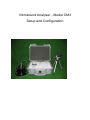
Vibrosound Analyser - Model CM3 Setup and Configuration CM3 Setup and Configuration Noise and Vibration Fast Set-Up Instructions 1) Connect Vibration and Microphone Sensors as required. See page 6 of the user manual for more details. 2) Ensure Power is available to cover the monitoring period. DO NOT ALLOW THE BATTERY TO GO FLAT, see pages 8 for more details. 3) Switch the unit on. If the modem option is fitted, wait for the network to log on. If you are not using the modem option, please press ‘Enter’ to bypass the modem logging on. 4) You will then be shown 3 screens of settings, press ‘menu’ to advance each screen until the base menu is shown. 5) Once at the base menu, press ‘2 - Continuous Monitoring’. 6) Close the lid ensuring no cables are trapped. 7) At the end of the monitoring period press the power button and wait for the event to save and the unit to power off. Note: For Software Versions 1.13 and above, and if the modem option is fitted, the CM3 will now send an SMS text alert when the internal battery is very low and then proceed to switch itself off soon after to protect the internal battery from damage. Adequate power in the form of a mains supply or an external power supply i.e a 12 V 110aH car battery, should be provided at all times to avoid seeing the warning text message. Depending on the ambient temperature and configurations installed on the CM3, you may get up to 8 hours after the warning text until the unit switches itself off, however this is not guaranteed. A basic set-up video can be found on our website by following the link below:www.surewavetechnology.co.uk/CM3DemoVideo/CM3 Demo 1.wmv [2] Issue 1.9 CM3 Setup and Configuration Table of contents Page Overview and Equipment Set-Up…………………………………………………………4-5 Equipment Set-up (Vibration)…………………………………………………...................6 Equipment Set-up (Noise), Charging the CM3…………………………………………6-8 Running Impulse Mode and Cut Off Delay………………………………...................9-10 Running Continuous Mode……………………………………………………………..11-12 Guidance on selecting and setting options……………………………………........13-19 External Alarm Option and Wind Option…………………………………………………20 Downloading from CM3 to PC and Modem Dial In using WMonitor Version 2………………………………………………………………………….............21-31 [3] Issue 1.9 CM3 Setup and Configuration Overview This document outlines the basic setup of the CM3, its sensors and cables. It is intended as a guide only and should be read in conjunction with any other CM3 documentation available. Please consult the latest promotional leaflet for specifications of the CM3. Specifications The equipment is a state of the art piece of electronic apparatus. When used correctly, it meets the requirements of a precision grade Type 1 noise analyser (if fitted) and a precision vibration and air over pressure monitor. As such, the equipment must be used in accordance with this manual and instructions given and reasonable care taken in its use and maintenance. In addition, for the requirements of various standards, including BS5228, the noise Leq’s should be user calibrated with a calibrated piston calibrator set to 94dB or other value (factory fit option only) before each major noise survey is undertaken. In addition, the equipment is guaranteed to provide the stated accuracy as per its specifications, subject to a 12-monthly calibration (return to base). This calibration should only be performed by SureWave Technology Ltd or a SureWave Technology approved agent to ensure appropriate accuracy and that all standards are met. Please consult the latest promotional leaflet for specifications of the CM3. Please Note: Under the Weee Directive, It is the responsibility of the customer to dispose of the equipment when it is no longer needed, or to return it to SureWave’s offices for disposal. [4] Issue 1.9 CM3 Setup and Configuration IMPORTANT: THE SEPARATE MAINS ADAPTER AND MAINS LEAD SHOULD NOT BE USED OUTSIDE OR IN ANY DAMP OR WET CONDITIONS! The Vibrosound Analyser Model CM3/QB3 is a low voltage unit and there are no hazardous voltages present. IMPORTANT: THERE ARE NO USER SERVICEABLE PARTS IN THE MAIN UNIT, TRANSDUCER, MICROPHONE, POWER SUPPLY OR CABLES. NO ATTEMPT SHOULD BE MADE TO OPEN, ADJUST OR DISMANTLE THESE ITEMS. ANY SUCH ATTEMPT WILL IMMEDIATELY INVALIDATE THE WARRANTY AND INVALIDATE THE CALIBRATION CERTIFICATE. IMPORTANT: USER PARAMETERS ARE ONLY SAVED WHEN THE OPTION MENUS ARE EXITED BY PRESSING 8. IF THE UNIT IS SIMPLY SWITCHED OFF WHILST IN THE OPTIONS PAGES, ANY CHANGES WILL BE LOST. IMPORTANT: PLEASE ENSURE THAT THE LID ON THE UNIT IS CLOSED EVEN IN LIGHT RAIN. THE UNIT IS FULLY SPLASH PROOF TO IP65 WITH THE LID CLOSED. IMPORTANT: IN HEAVY RAIN, PLEASE ENSURE THAT THE VIBRATION SENSOR IS COVERED, FAILURE TO OBSERVE THIS POINT WILL RESULT IN VIBRATION FROM THE RAIN AND IF THE VIBRATION SENSOR LEAD CONNECTOR IS NOT PLUGGED IN CORRECTLY, WATER INGRESS WILL RESULT IN HIGH READINGS. IF THIS HAPPENS PHONE SUREWAVE FOR ADVICE. WHEN IN OPERATION OUTDOORS, PERSISTENT LONG TERM EXPOSURE OF THE MICROPHONE TO ADVERSE WEATHER (RAIN) CAN RESULT IN REDUCED SENSITIVITY. SHOULD THIS OCCUR, THE MICROPHONE NEEDS TO BE GENTLY DRIED (BEST ACHIEVED BY PLACING IN A WARM ROOM). FORCED DRYING WITH HAIRDRYERS ETC SHOULD NOT BE CARRIED OUT. IF LONG TERM MONITORING IN ADVERSE WEATHER IS REQUIRED, IT IS SUGGESTED THAT A COVER IS POSITIONED APPROXIMATELY 0.5 – 1.0 METER ABOVE THE MICROPHONE TO SHELTER IT FROM DIRECT RAIN. CARE NEEDS TO BE TAKEN TO ENSURE NO REFLECTIVE WAVES OR OBSCURATION RESULTS FROM THE USE OF ANY COVER BY A MINIMUM DISTANCE OF 0.5 METERS. [5] Issue 1.9 CM3 Setup and Configuration Equipment Set-up Vibration The TA1 transducer (large black cylinder) should be placed on something solid, i.e. solid footpath or road for example and NOT on soft earth. It should be positioned at ground level, adjacent to any property being monitored. The arrow marked L (longitudinal) should point towards the source of vibration. This will make T (transverse) 90˚ to the vibration and V (vertical). This is the industry standard. The cable supplied should be pushed into the connector on top of the TA1 and into the side of the vibrosound into the socket marked Block A. Note: All the connectors are push fit and must not be turned to attach. To disconnect, the outer collar is pulled which will release the connector. Note: The connector should be first orientated to align the two halves before pushing in. If the seven-channel option has been purchased, position the second TA1 as required and connect to Block B on the side of the Vibrosound. Open the instrument case by lifting up the two clips. Lift the lid fully, to the vertical position. Push the On/Off button and the green light should illuminate. Follow the on-screen instructions or refer to the appropriate sections of this manual. Please follow instructions on Page 5 on how to protect the vibration head (TA1) in adverse weather conditions. Noise Set up the tripod supplied in the position required and fully extend the legs and wind up the top section using the handle and lock to the maximum height to give the correct height for the microphone. Position such that the microphone when clipped into its fastening on the top of the tripod is pointing towards the source of the noise. Ensure the windshield supplied is pushed on to the microphone. By aligning the two red dots, connect the supplied cable to the back of the microphone and connect the other end into the Vibrosound socket marked INT MIC. Open the instrument case by lifting up the two clips; lift the lid fully to the vertical position. Push the On/Off button and the green light should illuminate. Follow the on-screen instructions or refer to the appropriate sections of this manual. Microphone To comply with BS5228, the microphone should ideally be mounted 3 meters up and 0.5 meters out when monitoring noise on adjacent buildings. Long term monitoring will require a cover to protect the microphone from direct rain – mounted 0.5 meters above. Alternatively for short term monitoring, use the supplied tripod fully extended to its maximum height. [6] Issue 1.9 CM3 Setup and Configuration Please follow instructions on Page 5 on how to protect the microphone in adverse weather conditions. Ensure the sound meter base is correct for the range of noise to be monitored. Remember the dynamic range is approximately -10dB to +40dB from the base value. The unit can only be calibrated for sound on 60 or 80dB and the unit will automatically set the base value to 40dB, you can then change the sound meter base as required. Ensure that the base is one of these only: 20, 40, 60, 80, 100. 40dB will be the value after calibration. For regulative standards care should be taken to ensure: a. b. c. d. e. f. g. The microphone system is calibrated by the user before each new monitoring project and at regular intervals on long term monitoring. The height of the microphone system complies with BS5228. The supplied tripod ensures its height. All operators may be required to be “competent” persons as defined by the noise regulations and referred to in the ISO standards. The vibrosound must be calibrated by the manufacture at least as often as they state. For the Vibration head (TA1) this is 12 monthly. The Vibrosound Noise system is a type 1 precision grade system as defined by the ISO standards. This is the best type rating available. Results should only be interpreted by a competent trained person. SureWave Technology offers a reporting service. Price on application. Correct set-up is critical to obtaining correct meaningful results. If in doubt, ring SureWave Technology for free advice over the phone. [7] Issue 1.9 CM3 Setup and Configuration ** WARNING ** Flattening the battery in use to the point where the instrument no longer operates should be avoided where possible. If this does occur, the unit should be switched OFF and re-charged immediately using the above procedure. If possible, try and run the unit from the mains and put the unit on charge when not in use. If monitoring for long periods, please use an external battery source using the supplied crocodile clips. The external charger/ battery leads must never be connected to a voltage greater than 16V DC. A 12V battery is recommended. A 60aH external battery will run the unit for approx 20days. This will vary depending on exact settings and unit configuration particularly if the modem option is fitted. The user must replace the internal battery with an identical one. Failure to observe this may result in permanent damage to the unit. Please ring our offices for more information if needed. If using an external battery source, please ensure that the red lead (crocodile clip) is connected to the positive + terminal and that the black lead (crocodile clip) is connected to the negative - terminal Charging It is recommended that the unit is charged after each use. Connect the supplied power supply to your mains socket and plug the lead into the charger socket on the front panel of the unit. Fastest charging will be achieved with the main unit switched off. Turn the Vibrosound OFF. Switch the mains socket ON, the red power light should be lit and whilst charging, the amber light will be on. When fully charged, the amber light will automatically go off; the charger should then be switched off and disconnected. It is recommended that if the unit is to be stored for long periods without use, that it is charged for approximately one day every month or so. Failure to do this will result in a discharged battery, which may need to be replaced. The charger is automatic and can be safely left on without the risk of overcharging. If powering from the supplied mains adaptor, and you wish to close the lid to prevent tampering, please use the supplied external battery to charger adaptor lead. This connects to the external charge socket and provides a cable socket for you to plug in the mains charger. [8] Issue 1.9 CM3 Setup and Configuration Impulse Mode (Press 1 from the Base Menu) Introduction This mode is used to record impulse events. These are one-off type events lasting a second or so. The idea is to set a trigger level then enter the impulse mode and only when the trigger level is exceeded, will the unit wake up and record for the specified time and then go back to sleep whilst waiting for the next event. Results Given: Time and date set and triggered. User data if full print option selected. For each direction, vertical, longitudinal and transverse: Velocity (PPV) in mm/S Displacement in mm Acceleration in M/S/S Frequency of the peak in Hz Resultant Velocity (PPV) in mm/S Linear Air Overpressure in dB *Graphs of Vibration and Air Overpressure, if full print option is selected and quantity of graphs set. The graphs can either be combined (useful for observing the relationship between the channels and also saves paper) or separate. *External printer option is required. [9] Issue 1.9 CM3 Setup and Configuration User Parameters Relating to Impulse Mode. The following parameters can be changed by the user to suit their requirements. Event Length The length of the event in milliseconds (1000th of a second). Trigger Level The vibration level in PPV required to start an event. Cut–off Delay See Below Sound Meter Base The base level of the microphone system – for a Quarry Blast, it is suggested that this base would be set to 100 or 120dB as required. Valid ranges are 20, 40, 60, 80, 100, and 120dB. WARNING – Setting a base below 100dB may result in the microphone over-scaling and the unit indicating a lower blast value than actual. Sample Rate The number of samples per second on each channel, normally 1000. Full, Block and quantity of graphs. See Below. Print Options Alarm Levels Amber and Red alarm levels in PPV (option) for external beacon/siren or sms text alerts Cut-off Delay The best way to explain this is by example. If an event is expected to last 2 seconds maximum, then the event length would be set to 2000. If the cut-off delay was set to 500 for example, then if the event was shorter than expected, say 1 second, once the vibration falls below the trigger level and stays below for the cut-off delay time, then the event length will be reduced on this event only to 1000 + 500, giving an event length of 1.5 seconds. The user should take care to set the cut-off delay greater than any delay between detonators, for example, in Quarry Blasting. By using the cut-off delay, significant savings will be made in paper, pens and will also enable more events to be stored in the memory. *Print Options If the user selects block printout, the printer (if selected) will print just the table of values. Otherwise, user information, table results and graphs will be given. In this mode, when left unattended, the user can specify how many graphs should be printed before returning to block printout to save paper. *External Printer Option required [10] Issue 1.9 CM3 Setup and Configuration Continuous Mode (Press 2 from the Base Menu) Introduction This mode is used for monitoring of events from 5 minutes to several hours or continuous permanent 24 hour, 7 days a week. In this mode, the user can obtain vibration and noise Leq data. In addition, a sound only sub-mode enables the user to obtain Leq data for any time period chosen. The continuous modes can operate with or without a three period timer repeated daily. Results Given Sound & Vibration – Print At End Only Event start time, Event end time. User data if full print option selected. For each direction, vertical, longitudinal and transverse – Velocity (PPV) in mm/S Resultant Velocity (PPV) in mm/S Table of Vibration (velocity) Peaks per Interval (maximum of 96 giving 5 minute values for an 8 hour event) in mm/S Noise (Leq) Option if fitted LMAX , MAX 5 minute Leq, overall Leq, percentiles L1, L10, L90 and table of Leq and 5 minute Leq per interval all in dB (A) Histograms of vibration and Leq noise (if printer option is fitted and full print-option selected) Results Given Sound Only The printer will print the Leq, LMAX, MAX 5 minute Leq, L1, L10 and L90 for every interval the user selected. [11] Issue 1.9 CM3 Setup and Configuration User Parameters Relating to Continuous Mode C Mode Timer ON or Off Table Time Interval See Below Alarm Option Either used to produce the time interval for the table or the event length if the timer is off. As In Impulse mode with the graphs becoming histograms of the vibration and noise. Base at which the noise will be monitored above. The microphone has approximately 50dB dynamic range, so as a guide for daytime noise surveys, a base of 60dB would give 55 to 110dB and night time, a base of 20 or 40dB may be selected. Valid ranges are 20, 40, 60, 80, 100 and 120dB only. See Impulse Mode above. Sound & Vibration Print at End Only or Sound Only In sound only mode, the print interval defines the Leq time period for the printout. This enables the user to obtain any Leq period greater than 5 minutes. Print Options Sound Meter Base Continuous Mode Timer ON The unit will produce an event for each of the three time periods. If a period is not required, setting the start and end time to the same values will skip that period. The time periods are repeated daily. See the details of options section for correct setting of these times. Each event produced by the time period will be tabulated using the table time interval set by the user. Note: At present, there is a maximum of 96 intervals per time period. Continuous Mode Timer OFF The unit will start an event upon selection of the continuous mode; the event length will be the table time interval set by the user. As soon as the results are displayed and optionally printed, the next event will start for the same duration. This will continue until the user stops the monitoring. Reprinting Events (Press 4 From the Base Menu) Selecting this option (Option 4 – Reprint Events) will enable any of the first 10 events to be displayed or printed (depending on the print setting and whether the printer option is fitted). The unit will first search for the events (may take a few minutes depending on the quantity of events in the store). Only the first 10-event date and times will be displayed. To reprint (or display), enter the event number, 0 to 9 and press ENTER. [12] Issue 1.9 CM3 Setup and Configuration Guidance on Selecting & Setting Options Options Page 1 1: Trigger Level 2: Sound Meter Base 3: Event Length 4: Cut-Off Delay 5: Toggle Print Mode 6: Date/Time 7: User Data 8: Exit MENU: Next Options Page Options Page 2 1: Alarm Limits 2: Table Time 3: C-Mode Timer 4: Sound Only (On or Off) 5: Sampling Rate 6: User Cal of Leqs 7: PC Link - Monitor 8: Exit MENU: Previous Menu Changing Values used in User Settable Parameters When you need to input a new value, press the appropriate keys to give the number required and where required, press enter to input this number. If a mistake is made, press ENTER and then re-select the option to re-do. Note: On user data, use the left arrow key to re-do characters as required. See the details of options section for more information. Sometimes, the ENTER key will not be required, for example, if the maximum number size is four digits, entering the fourth digit will automatically accept the number without pressing ENTER. This will be clearly evident on the screen. IMPORTANT – AFTER ANY CHANGES ARE MADE, PLEASE PRESS 8 – EXIT AND SAVE THE CHANGES. [13] Issue 1.9 CM3 Setup and Configuration Details of Options Trigger Level Used in impulse or dual modes. The level of vibration which when exceeded will initiate an event. Also, used for the cut-off delay. Valid ranges: 0.01 to 99.8 in millimetres per second PPV. The trigger level can be user selectable, Sound/Air Overpressure: dB above the Sound Meter Base (Linear) (ON or OFF). To change the Trigger Level, go to Options Menu 1, then 1 – Trigger Level, enter the value, then select ‘4 or 7 channel’, then select ‘2’ when asked if you wish to trigger on noise (in continuous mode). Sound Meter Base The base level for the microphone system. The unit will record from -10dB below this level to 40dB above minimum. Valid entries: 20, 40, 60, 80, 100, 120. Typically set to 100 or 120 for quarry blasting, 20 or 40 for night time noise monitoring and 40 or 60 for daytime noise monitoring. To change the Sound Meter Base, go to Options Menu 1, then 2 – Sound Meter Base. Press 8 to exit and save any changes. Event Length Used only in impulse mode. Set to equal an anticipated impulse event duration. Typically 1500 to 2000 for a quarry blast in milliseconds. Valid ranges: 500 to 9990. 9999 will give maximum length based on the current sampling rate. To select Event Length, go to Options Menu 1, then 3 – Event Length. Press 8 to exit and save any changes. Cut-off Delay The best way to explain this is by example. If an event is expected to last 2 seconds maximum, then the event length would be set to 2000. If the cut-off delay was set to 500 for example, then if the event was shorter than expected, say 1 second, once the vibration falls below the trigger level and stays below for the cut-off delay time, then the event length will be reduced on this event only to 1000 + 500, giving an event length of 1.5 seconds. User selectable from 0.1 to 1 second. The user should take care to set the cut-off delay greater than any delay between detonators, for example, in quarry blasting. By using the cut-off delay, significant savings will be made in paper and pens and will also enable more events to be stored in the memory. To select Cut-off delay, go to Options Menu 1, then 4 – Cut-off delay. Press 8 to exit and save any changes. Toggle Print Mode (External Printer Option Required) Short (block) print option gives table information only, full gives user data, table information and graphs with the option to select single or combined graphs and the quantity of graphs printed when left unattended. [14] Issue 1.9 CM3 Setup and Configuration Date & Time Use to enter current date and time information. Follow the format given on the screen, i.e, 2 digits then the dot (.) key followed by the next 2 digits etc. The date and time is also displayed at switch on. Please check after resetting. To set the date and time, go to Options Menu 1, then 6 – Date/Time. Press 8 to exit and save any changes. User Data The User Data enables the user to enter information relevant to them and setup SMS text alerts. Set in five parts, heading, data, SMS data, SMS alerts and SMS country code. To input user data select option 1 heading or option 2 data, each can be 10 characters, use the to redo any character, the for the next character, to scroll through the characters. Press ENTER when finished. To delete previous characters use spaces after the word if not simply press enter, then enter again. To change SMS Data (SMS text numbers), select option 3, your current numbers will be shown. Select 1 to change or 0 to go back. Up to 4 text numbers can be stored. To set SMS text alerts, select option 4, press 0 to disable alerts, 1 to enable alerts sending a SMS text only once or 2 to enable alerts sending repeated SMS texts. If SMS text alerts are enabled you will be prompted for the SMS message centre (see details under Modem Option for message centre numbers 1 – 7 for O2, Vodafone etc…) To change the SMS country code, select option 5 choose 1 for United Kingdom (+44) or 2 for Australia (+61). When you are happy with your settings select Option 6 All done (Menu), finally press ‘8’ to exit and save your settings. [15] Issue 1.9 CM3 Setup and Configuration Alarm Limits (option if fitted Modem SMS or External Alarms) There are 5 alarm limits. Points to note – If the alarm value is not required, it must be set to zero and for entering decimal alarm values, enter the full number including point, i.e, 1.5. Alarm 1 is the amber warning level for peak vibration, this triggers a strobe output on an external alarm unit and sends a SMS text alert, in mm per second PPV, any channel. Alarm 2 is the red warning level for peak vibration, this triggers the sounder output on an external alarm unit and sends a SMS text alert, in millimetres per second PPV, any channel. You will then be asked for an alarm time delay, unless this is needed, please enter zero. The alarm time option is used for example if monitoring next to a railway line and is designed to allow sufficient time for a train to go past before sounding the vibration alarm. In other words vibration above the alarm value is ignored for the delay time entered. Alarm 3 is 1 minute average LAeq, - sends SMS text alerts. This will also trigger the strobe output if external alarm option is fitted. Alarm 4 is the table time (e.g 15 minute) average LAeq – sends SMS text alerts. This will also trigger the strobe output if external alarm option is fitted. Alarm 5 is the period time (e.g 8 hour) average LAeq – sends SMS text alerts. This will also trigger the strobe output if external alarm option is fitted. To change alarm limits, go to Options Menu 2, then 1 – Alarm Limits. Press 8 to exit and save any changes. [16] Issue 1.9 CM3 Setup and Configuration Modem Option This option gives remote data access and SMS text alerts on 5 alarm levels (2 Vibration and 3 Noise) and new ‘Real Time’ remote readings. The download intervals are fully user selectable. If the unit is fitted with a Modem, the user can select to send SMS messages. Use this option to select, (1 = SMS) or (0 = No SMS), under User Data, Options Menu 1, then 7 – User Data, then 3 – Change SMS Data, then 4 – Alarm SMS Alerts. If selected the unit will ask for a message centre number. This must be input according to the following list:UK +44 Australia +61 1: O2 Optus 2: Vodafone Telstra 3: Virgin Vodafone 4: Three Three 5: Orange Optus (without +61) 6: T-Mobile Vodafone (without +61) 7: Tesco UK Vodafone The numbers to text are stored under user data – Options Menu 1, then 7 – User Data, then 3 – Change SMS Data. Press 8 to exit and save any changes. Table Time With the continuous mode timer ON, this is the time used to tabulate the table in minutes (maximum 96 table intervals per timer period). With the timer switched OFF, it then becomes the event length. To select the Table Time, go to Options Menu 2 then select 2 – Table Time, this will enable you to set the table time. Press 8 to exit and save any changes. Please Note – The Table Time cannot be currently set lower than 5 minutes. [17] Issue 1.9 CM3 Setup and Configuration C Mode Timer Enables the user to view, select timer on or off and change timer settings. **WARNING** The first timer period must start and end before the second timer period. The second timer period must start after the first and end before the third timer period and the third timer period must start after the second timer period and end before the first, i.e, to monitor 24 hours, the following settings would be valid: Start Timer A 06:00 Timer B 14:01 Timer C 22:02 End 14:00 22:01 05:59 Note: Timer C goes to the next day. To set the timer, first go to Options Menu 2, and then select 3 – C Mode Timer, you can then turn the timer on/off and change the timer settings. Press 8 to exit and save any changes. Sound & Vibration or Sound Only Option Sound & vibration will give vibration and noise Leqs at the end of the event. Sound Only gives LMAX, Leq, MAX 5 minute Leq, L1, L10 and L90 values. Sampling Rate Normally set to 1000 (recommended). It can be reduced to give longer event lengths in impulse mode only. It is recommended that the sampling rate is at least 10 times the frequency of vibration being monitored. It is not recommended setting this to anything other than 1000, unless required to increase the event length. In continuous mode, the sampling rate is fixed at 1000. To select the Sampling Rate, go to Options Menu 2, then 5 – Sampling Rate. Press 8 to exit and save any changes. User Cal of Leqs. The on screen instructions must be followed to the letter. A piston calibrator switched on producing 94.0 dB must be firmly fitted to the microphone and the microphone connected correctly to the unit before proceeding. **WARNING** Failure to calibrate correctly will result in incorrect Leq readings permanently, until recalibrated. [18] Issue 1.9 CM3 Setup and Configuration Procedure for User Cal of Leqs: With the microphone correctly connected to the unit and the piston calibrator switched on at 94.0 dB and firmly positioned on the microphone, select this option. Select Option Menu 2, then 6 – User Cal of Leq’s. Only press MENU to start when you are sure the piston calibrator is correctly set and on and the cable is correctly connected. Press MENU. The display should show 94.0 +/- 0.5dB. If any other value is shown, immediately ring for technical support and assistance. Assuming the above value is shown, switch the piston calibrator off and observe the reading on the screen falling to approximately the sound meter base. If this happens, then you have correctly calibrated your system. Note: There is a factory option for different calibrators to be used. If this applies to you, then the 94dB given above will be the value of your piston calibrator. ** WARNING ** You must proceed to save the calibration value by pressing MENU to exit and then 8 to exit and save the menu options. After the calibration detailed above, the sound meter base will be automatically set to 40dB. This is correct to monitor most sites, but for very quiet (country) sites at night; this should be changed to 20dB. Equally, if monitoring a very noisy site, with the noise expected to exceed 90 to 100dB, then the base should be changed to 60dB [19] Issue 1.9 CM3 Setup and Configuration Other Options: External Alarm Option: The External Alarm Option consists of the following items: 1) 2) 3) 4) Mains powered external alarm box. Cable that connects the external alarm box to the Vibrosound. Beacon that connects to the alarm box. Sounder that connects to the alarm box. The External Alarm option is mains powered and should be protected from adverse weather conditions. The beacon and sounder are water/splash proof and both come supplied with a 12 meter cable. To Operate: When this option is used, alarms 1, 3, 4 & 5 will activate the beacon alert when the noise/vibration limits are exceeded. If the alarm limits are exceeded on alarm 2 – red alert for vibration, the sounder will be activated. 1) 2) 3) 4) 5) Set up your alarm parameters as detailed on Page 16 under ‘Alarm Limits’. Connect the external alarm box to the Vibrosound. The socket is located on the back of the Vibrosound. Connect the beacon and the sounder to the external alarm box. Plug the external alarm box into a mains power source. Set the Vibrosound monitoring as normal. Wind Option: The Wind Option consists of the following items: 1) 2) Weather Vane with 20 meter cable. User to provide their own 10 meter pole. To operate: 1) 2) 3) 4) The weather vane plugs directly into the Vibrosound in the socket labelled ‘Wind’. Mount the weather vane onto the pole; this must be mounted 10 meters above the ground to comply with the ETSU-R-97 standard. The weather vane must be pointing ‘North’, it may be necessary to weigh the base down with sandbags to secure. Set the vibrosound monitoring as normal, you will get the following values: Noise Vibration Wind Speed, Peak Gust and Direction. The table time must be set at 10 minute intervals to comply with ETSU-R-97. [20] Issue 1.9 CM3 Setup and Configuration How to download data from CM3 to PC WMonitor Version 2 IMPORTANT – Do not connect the USB cable until the WMonitorV2 software has been installed! WMonitor – Version 2 – Installation The WMonitorV2 software is compatible with Microsoft™ Windows 2000, XP, Vista and Windows 7 platforms. You will require 1 free USB port if downloading via cable or a modem if downloading remotely. Ensure you have administrative rights on your computer before installing the WMonitor software.Insert CD into your computers CD ROM drive and then follow the instructions on your screen. If you are prompted for an administrator password or confirmation, type the password or provide confirmation Note: If WMonitor is minimized on the task bar and will not return to the screen do the following: 1 2 Right click on the task bar and select cascade or Highlight the small icon and press alt and space (together) then ‘move’ from the pop up menu. Press the up arrow (DO NOT TRY to drag) until the window is all on the desktop as required. Causes: This is a known bug in Windows 7, and often happens when using a laptop or PC without a mouse. Or, the window is dragged onto the task bar. The above notes will fix – This is not an issue or bug in the WMonitor program. [21] Issue 1.9 CM3 Setup and Configuration Downloading the data using the USB cable CM3 Vibrosound When at the base menu, select ‘5’ for options Press ‘Menu’ for the next options list Select option 7 – PC Link – Monitor Make sure PC Link cable (USB A – USB B, see drawing on page 20), USB B is attached to the CM3 and USB A is attached to the computer. Select ‘1’ to download to wmonitor or ‘3’ to clear store, (after first making sure that you have downloaded all results, because once they have been cleared there is no getting them back). 1) 2) 3) 4) Computer 1) 2) 3) 4) 5) 6) Select ‘wmonitor.exe’ program Click on File then Connect you will be prompted for a filename, enter a name then click Save. Highlight the CM3 then click on ‘Connect’ Click ‘OK’ when instrument is ready. The CM3 should then download any available event data The CM3 will automatically have gone back to the 2nd Options Menu. Note: When downloading via the download cable, please ensure that the CM3 unit’s memory is cleared manually before commencing monitoring to avoid the memory overflowing. Follow step s 3 & 4 under ‘CM3 Vibrosound’ instructions above, then select ‘3-Clear Store’ then ‘1-Yes’, unit will say ‘Memory Cleared’ then press ‘8-Exit’ and save. Please check on switch on that the CM3 says 0 Events and 0% Used. Downloading the data using the modem dial-in option ** WARNING ** Switch off power before installing or removing the SIM card The modem dial-in option is only available when the CM3/QB3 is in a monitoring mode. 1) 2) 3) 4) Select ‘wmonitor.exe’ program Click on File then Connect you will be prompted for a filename, enter a name then click Save. Highlight the site number you require then click on ‘Connect’ Click ‘OK’ when instrument is ready. [22] Issue 1.9 CM3 Setup and Configuration 5) 6) The CM3 should then download any available event data The CM3 will automatically have gone back to the 2nd Options Menu. ** WARNING ** After downloading the data, please ensure the Vibrosound’s memory is cleared to avoid the memory getting full. If the memory is not cleared this could result in missing/corrupt data. The response to the point to clear the data waits for seconds only, so you need to click ‘clear’ and ‘yes’ immediately. On the next dial in, please check that the data was cleared from the previous download, if this hasn’t happened (due to poor modem signal) a site visit will be necessary to clear the Vibrosound manually. WMonitor V2 Vibrosound Data Analysis Program About This data Analysis program is a powerful statistical tool which has been designed primarily to download batches of information from the Magus and SureWave Vibrosound range of vibration and noise instruments. Warning: This computer program is protected by copyright law and international treaties. Unauthorized reproduction or distribution of this program, or any portion of it, may result in severe civil and criminal penalties, and will be prosecuted to the maximum extent possible under the law. Vibrosound devices are manufactured by Magus Electronics. Copyright ©2012 SureWave Technology Ltd, All rights reserved. Opening Existing Files To open an existing raw file, from the File menu click Open or click the icon on the tool bar. An open file dialog will be shown, select the .raw file you wish to open then click Open. When the file is loaded the data results will be shown on screen. [23] Issue 1.9 CM3 Setup and Configuration Connecting to a Vibrosound (via Cable or Modem) From the File menu click Connect or click the icon on the tool bar. You will be prompted to give a file name for the saved data to be stored. Enter a suitable filename then click Save. The download dialog window will appear. For a cable connection, select CM2 or CM3 from the left index. Unless you know the specific serial port number, choose Automatic. Click the Connect button and follow the information on screen. Note for a modem connection to work, the Vibrosound device must be monitoring either C-Mode or I-Mode. When downloading via the modem you will be prompted to clear the data if required. Once the data is successfully downloaded it will be displayed on screen. [24] Issue 1.9 CM3 Setup and Configuration Exporting Data In some versions data can be exported either to an ASCII file or Excel™ file. To export to Excel, from the file menu click Export then Excel File or click the on the toolbar. You will be prompted to give the Excel file a name, click Save to continue. icon To export to ASCII, from the file menu click Export then click ASCII File or click the icon on the toolbar. You will then be prompted to give the ASCII file a name, click Save to continue. Printing Data The data can be printed in table form to a printer, from the file menu click Print or click the icon on the toolbar. Closing the program To close the program from the File menu, click Exit or click the icon on the toolbar. Site Database The site database holds data numbers if using the modem option, to open the site database from the Settings menu click Site Database or click the toolbar. The site database window will be shown. [25] Issue 1.9 icon on the CM3 Setup and Configuration To add a new entry, click the Add New button. Enter a name for the site, an address (if required) a telephone number (the data number of the SIM card in the Vibrosound) and a memo (if required). When ready click the Save button. To change or delete an existing entry, select its site name from the index list on the left side. To delete the entry, click the Delete button. To update the entry, make the changes required then click the Update button. Note: To exclude a number from dialing with a download schedule set, put the word “EXCLUDE” without the quotes in the Plant Memo box. The number will then be skipped during a scheduled download. Note: The site name cannot be changed once it is set. Note: CM2 and CM3 cable connections cannot be deleted. Download Schedule If a download schedule is set, the program will automatically connect to remote Vibrosound devices at the specified time and day. To set the schedule, from the Settings menu click the download schedule window will appear. [26] Issue 1.9 icon on the toolbar. The CM3 Setup and Configuration The settings are a day of the week, daily or time interval. Select this interval from the drop down box then set the time from the time box. Select a folder where the downloaded raw files will be saved. Click Enable Schedule to enable the download then click Close. The download schedule will be shown in the status strip on the main application window. Viewing Data [27] Issue 1.9 CM3 Setup and Configuration The data is displayed on a grid view, showing the peak events within a given time period. To expand on the data, double click on any number within the selected row. There a 2 types of event Continuous Mode (C Mode) and Impulse Mode (I Mode). The event types are shown separately to change the view from the View Menu click Continuous Mode Events or Impulse Mode Events. Alternatively from the toolbar click mode events. for continuous mode events or for impulse Peak Events The absolute peak vibration and noise events will be highlighted in red and are shown at the bottom of the window. These are the overall peak events for a given set of data. To highlight the peak events, use the View menu, click Highlight Peak Events and choose Vibration or Noise. The selected line on the data grid will then be the peak values. C Mode [28] Issue 1.9 CM3 Setup and Configuration The C-Mode Data Analysis window will be shown if a C-Mode event is double clicked from the main screen. Peak values for this particular event are shown at the top of the screen. To display the next or previous event set click the at the bottom of page. Click the Close button to close this window. buttons I Mode The I-Mode Data Analysis window will be shown if a I-Mode event is double clicked from the main screen. Peak values for this particular event are shown at the top of the screen. [29] Issue 1.9 CM3 Setup and Configuration To display the next or previous event set click the at the bottom of page. Click the Close button to close this window. buttons Software Version To check which version of the software you are running from the help Menu click About WMonitor the about window will be shown. [30] Issue 1.9 CM3 Setup and Configuration To check for software updates, from the help menu click Check for Updates, if an update is available you will be notified with instructions on how to download and install it. [31] Issue 1.9