1
ipLDK-20/100/300/300E
Feature Description
and Operation Manual
-20/100/300/300E Version 3.8
Feature Description and Operation Manual
Issue 1.0
September, 2008
Copyright© 2008 LG-Nortel Co.,Ltd. All Rights Reserved
This material is copyrighted by LG-Nortel Co.,Ltd. (LGN). Any unauthorized reproductions, use or disclosure of
this material, or any part thereof, is strictly prohibited and is a violation of Copyright Laws. LGN reserves the
right to make changes in specifications at any time without notice. The information furnished by LGN in this
material is believed to be accurate and reliable, but is not warranted to be true in all cases.
All other brand and product names are trademarks or registered trademarks of their respective companies.
-20/100/300/300E Version 3.8
Feature Description and Operation Manual
Issue 1.0
September, 2008
Revision History
ISSUE
1.0
DATE
Sep. 2008
Contents of Changes
Initial Release for ipLDK-20/100/300/300E v3.8
REMARK
-20/100/300/300E Version 3.8
Feature Description and Operation Manual
Issue 1.0
September, 2008
Table of Contents
1 INTRODUCTION ................................................................................................... 1
1.1 Manual Usage .................................................................................................................... 1
2 SYSTEM FEATURE.............................................................................................. 2
2.1 Incoming Call ..................................................................................................................... 2
2.1.1 Ring Assignment....................................................................................................................... 2
2.1.2 Preferred Line Answer (PLA).................................................................................................... 3
2.1.3 Direct Inward Dialing (DID) ....................................................................................................... 4
2.1.4 Direct Inward System Access (DISA)....................................................................................... 5
2.1.5 Customer Call Routing (CCR) with VMIB................................................................................. 6
2.1.6 CO Line Name .......................................................................................................................... 8
2.1.7 Universal Answer (UNA)........................................................................................................... 8
2.2 Outgoing Call Access ..................................................................................................... 10
2.2.1 Basic Access........................................................................................................................... 10
2.2.2 Call Time Restriction............................................................................................................... 11
2.2.3 CO Line Queuing .................................................................................................................... 12
2.2.4 CO Step Call – Analog Only ................................................................................................... 12
2.2.5 Emergency Call Service ......................................................................................................... 13
2.2.6 Hot Line & Warm Line............................................................................................................. 13
2.2.7 Least Call Routing (LCR)........................................................................................................ 14
2.2.8 Memory Dialing ....................................................................................................................... 17
2.2.9 Private Line ............................................................................................................................. 23
2.2.10 Dialing Service by Prefix code (for Ukraine)......................................................................... 23
2.3 Rerouting.......................................................................................................................... 24
2.3.1 Call Forward............................................................................................................................ 24
2.3.2 Call Transfer............................................................................................................................ 32
2.3.3 Holding and Parking................................................................................................................ 34
2.3.4 Pickup...................................................................................................................................... 37
2.3.5 IP Phone Rerouting................................................................................................................. 39
2.4 Call Handling.................................................................................................................... 40
2.4.1 Absent Text Message ............................................................................................................. 40
2.4.2 Alarm ....................................................................................................................................... 42
2.4.3 Automatic Privacy ................................................................................................................... 42
2.4.4 BGM (Background Music)....................................................................................................... 43
2.4.5 Camp-on ................................................................................................................................. 44
2.4.6 Change Ring Type .................................................................................................................. 45
2.4.7 Data Line Security................................................................................................................... 45
2.4.8 Dialing Security ....................................................................................................................... 46
2.4.9 DND (Do Not Disturb) ............................................................................................................. 47
2.4.10 One Time DND (Do Not Disturb) .......................................................................................... 47
2.4.11 Flash...................................................................................................................................... 48
2.4.12 Flexible Buttons..................................................................................................................... 48
2.4.13 Headset................................................................................................................................. 50
2.4.14 Intercom Signal Mode........................................................................................................... 51
2.4.15 Intercom Tenancy Group ...................................................................................................... 52
2.4.16 Message Wait / Call Back..................................................................................................... 53
2.4.17 MOH (Music On Hold) .......................................................................................................... 54
2.4.18 Mute ...................................................................................................................................... 56
2.4.19 MWI (Message Wait Indication) – SLT Feature ................................................................... 56
2.4.20 On-Hook dialing .................................................................................................................... 56
i
-20/100/300/300E Version 3.8
Feature Description and Operation Manual
Issue 1.0
September, 2008
2.4.21 Station Name ........................................................................................................................ 57
2.4.22 Station Programming ............................................................................................................ 59
2.4.23 Station Relocation................................................................................................................. 60
2.4.24 Station Serial Call ................................................................................................................. 61
2.4.25 Time & Date Setup (Digital Network) ................................................................................... 61
2.4.26 Voice Over ............................................................................................................................ 61
2.4.27 Wakeup ................................................................................................................................. 62
2.4.28 Automatic Fax Transfer ........................................................................................................ 63
2.4.29 Mobile Extension................................................................................................................... 64
2.4.30 Remote control with Mobile Extension ................................................................................. 66
2.4.31 Extend CO-to-CO Connection .............................................................................................. 66
2.4.32 Forced Hands-free Mode...................................................................................................... 67
2.4.33 Hot Desk ............................................................................................................................... 67
2.4.34 Analogue CLI Display ........................................................................................................... 68
2.4.35 Call Log ................................................................................................................................. 69
2.4.36 In-Room Indication................................................................................................................ 70
2.4.37 Chime Bell............................................................................................................................. 70
2.4.38 Emergency Intrusion ............................................................................................................. 71
2.4.39 Forced Trunk Disconnect...................................................................................................... 72
2.4.40 Barge In................................................................................................................................. 72
2.4.41 Station Call Coverage........................................................................................................... 73
2.4.42 Station Port Blocking............................................................................................................. 74
2.4.43 DND Operation of Pre-selected MSG Station ...................................................................... 75
2.4.44 DID/DISA Call Routing of DND Station ................................................................................ 75
2.4.45 Incoming CO Ring assignment to Networking System ........................................................ 76
2.5 Call Barring ...................................................................................................................... 77
2.5.1 Account Code.......................................................................................................................... 77
2.5.2 Authorization Code ................................................................................................................. 78
2.5.3 Automatic Call Release........................................................................................................... 79
2.5.4 Class Of Service (COS).......................................................................................................... 80
2.5.5 System Speed Zone ............................................................................................................... 82
2.5.6 Walking COS........................................................................................................................... 82
2.6 Hunt Group....................................................................................................................... 83
2.6.1 Common Hunt Group Features .............................................................................................. 83
2.6.2 Terminal Group ....................................................................................................................... 85
2.6.3 Circular Group......................................................................................................................... 85
2.6.4 Ring Group.............................................................................................................................. 86
2.6.5 Voice Mail Group .................................................................................................................... 86
2.6.6 UCD Group (Unified Call Distribution) .................................................................................... 87
2.6.7 ACD (Automatic Call Distribution) .......................................................................................... 88
2.7 Conference....................................................................................................................... 93
2.7.1 Conference – SLT (Brokers Call) ........................................................................................... 94
2.7.2 Paging Conference ................................................................................................................. 95
2.7.3 Conference Room................................................................................................................... 95
2.8 Paging feature ................................................................................................................. 97
2.8.1 Internal, External, All-Call, and Meet-Me Page ...................................................................... 97
2.8.2 Pre-recorded MSG.................................................................................................................. 98
2.8.3 SOS Paging ............................................................................................................................ 99
2.8.4 Push-to-Talk (PTT) ............................................................................................................... 100
2.9 Linked Stations.............................................................................................................. 101
2.9.1 Executive/Secretary .............................................................................................................. 101
2.9.2 Linked-Pair Station................................................................................................................ 103
2.10 External Device Control.............................................................................................. 105
2.10.1 Door Open........................................................................................................................... 105
ii
-20/100/300/300E Version 3.8
Feature Description and Operation Manual
Issue 1.0
September, 2008
2.10.2 Door Phone ......................................................................................................................... 106
2.10.3 Loud Bell ............................................................................................................................. 107
2.11 Voice Service ............................................................................................................... 108
2.11.1 Recording System VMIB Announcement........................................................................... 108
2.11.2 Remote Control................................................................................................................... 110
2.11.3 Two-way Recording ............................................................................................................ 112
2.11.4 Recording User VMIB Announcement ............................................................................... 114
2.11.5 VMIB Announcement for Auto Attendant ........................................................................... 115
2.11.6 VMIB Message Transfer ..................................................................................................... 116
2.11.7 VMIB Message with CLI ..................................................................................................... 116
2.11.8 No Answer Call to VMIB ..................................................................................................... 117
2.11.9 Direct Transfer to VMIB ...................................................................................................... 117
2.11.10 DID Call to Each Station Voice Mail Box.......................................................................... 118
2.11.11 CCR Call to Each Station Voice Mail Box ........................................................................ 118
2.12 SMDR (Station Message Detail Recording).............................................................. 119
2.12.1 AOC (Advice Of Charge) .................................................................................................... 121
2.12.2 Print-out............................................................................................................................... 122
2.13 Attendant Service........................................................................................................ 123
2.13.1 Assign Attendant................................................................................................................. 124
2.13.2 Attendant Call & Queuing ................................................................................................... 124
2.13.3 Attendant Forward .............................................................................................................. 125
2.13.4 Attendant Intrusion.............................................................................................................. 126
2.13.5 Attendant Override.............................................................................................................. 127
2.13.6 Attendant Recall.................................................................................................................. 128
2.13.7 Change LCD Date/Time display ......................................................................................... 128
2.13.8 Day/Night Service ............................................................................................................... 129
2.13.9 Disable Outgoing Access.................................................................................................... 130
2.13.10 ICM Box Music Selection.................................................................................................. 131
2.13.11 Station Feature Cancel ..................................................................................................... 131
2.13.12 DSS/DLS Consoles .......................................................................................................... 132
2.14 ISDN Service ................................................................................................................ 133
2.14.1 Call Deflection/Rerouting .................................................................................................... 133
2.14.2 CLI (Calling Line Identification Presentation) ..................................................................... 134
2.14.3 CLIR/COLR ......................................................................................................................... 140
2.14.4 COLP (Connected Line Identification Presentation) .......................................................... 140
2.14.5 Key Pad............................................................................................................................... 140
2.14.6 Malicious Call ID ................................................................................................................. 142
2.14.7 MSN/Sub-Addressing ......................................................................................................... 142
2.14.8 ISDN Supplementary .......................................................................................................... 144
2.14.9 DID Call Destination with Incoming CLI ............................................................................. 148
2.15 VOIP Service ................................................................................................................ 150
2.15.1 Call by IP address............................................................................................................... 150
2.15.2 Call by Routing Table.......................................................................................................... 151
2.15.3 Normal/Fast mode for H.323 .............................................................................................. 151
2.15.4 Early H.245 ......................................................................................................................... 152
2.15.5 H.245 Tunneling.................................................................................................................. 152
2.15.6 DiffServ................................................................................................................................ 152
2.16 H.450 over IP................................................................................................................ 154
2.16.1 Net Call................................................................................................................................ 156
2.16.2 VOIP Networking ................................................................................................................ 157
2.16.3 Identification Service........................................................................................................... 159
2.16.4 Net Transfer ........................................................................................................................ 159
2.16.5 Net Call Forward ................................................................................................................. 161
2.16.6 Net Conference................................................................................................................... 164
iii
-20/100/300/300E Version 3.8
Feature Description and Operation Manual
Issue 1.0
September, 2008
2.16.7 Call Offer ............................................................................................................................. 165
2.16.8 Call Completion................................................................................................................... 166
2.16.9 Do-Not-Disturb (DND)......................................................................................................... 167
2.16.10 CO Transit - In................................................................................................................... 168
2.16.11 CO Transit - Out................................................................................................................ 169
2.16.12 Message Waiting Indication (MWI)................................................................................... 172
2.16.13 Absent Text Message ....................................................................................................... 173
2.16.14 Attendant Call Service (CAS) ........................................................................................... 173
2.16.15 Centralized VMS ............................................................................................................... 174
2.16.16 Busy Lamp Field (BLF) ..................................................................................................... 174
2.16.17 Net Follow-Me Forward .................................................................................................... 176
2.16.18 Centralized SMDR for Transit Call ................................................................................... 177
2.16.19 DECT Mobility ................................................................................................................... 177
2.16.20 NET Firewall routing ......................................................................................................... 178
2.16.21 Security of Transit-Out Code with registered IP............................................................... 178
2.17 2B Function.................................................................................................................. 179
2.18 Traffic Analysis............................................................................................................ 180
2.18.1 Attendant Reports ............................................................................................................... 181
2.18.2 Call Reports ........................................................................................................................ 182
2.18.3 CO Reports ......................................................................................................................... 183
2.18.4 Hardware Unit Reports ....................................................................................................... 184
2.19 Software Upgrade........................................................................................................ 185
2.19.1 ISDN.................................................................................................................................... 185
2.19.2 LAN ..................................................................................................................................... 187
2.19.3 SERIAL (COM port) ............................................................................................................ 189
2.19.4 MODEM .............................................................................................................................. 191
2.20 SIP................................................................................................................................. 193
2.20.1 Incoming Call ...................................................................................................................... 194
2.20.2 Outgoing Call ...................................................................................................................... 195
2.20.3 Register ............................................................................................................................... 196
2.20.4 Private Extension ................................................................................................................ 197
iv
-20/100/300/300E Version 3.8
Feature Description and Operation Manual
Issue 1.0
September, 2008
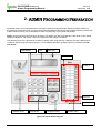
1 INTRODUCTION
This Programming Manual is designed to provide general system features and ADMIN Programming using a
DKTU and PC for the ipLDK. This manual contains the following sections.
1.1 Manual Usage
This section is a functional listing of features with the description and operation of each. The structure is
divided into 5 parts as listed:
Description: explains the nature of the feature.
Operation: describes how to use the feature.
Condition: explains any requirements or constraints of the feature related to its configuration.
Reference: lists related topic information to aid in understanding the feature.
Admin Programming: descriptions and instructions for setting-up System and features.
1
-20/100/300/300E Version 3.8
Feature Description and Operation Manual
Issue1.0
September, 2008
2 SYSTEM FEATURE
2.1 Incoming Call
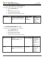
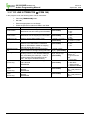
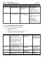
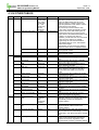
2.1.1 Ring Assignment
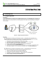
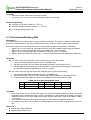
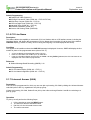
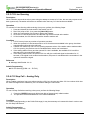
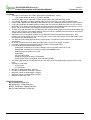
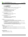
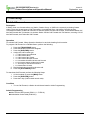
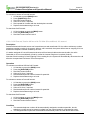
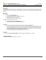
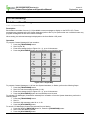
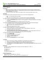
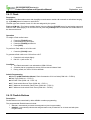
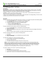
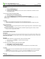
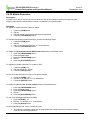
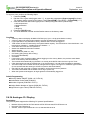
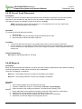
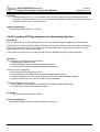
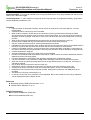
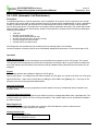
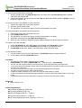
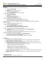
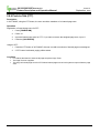
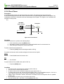
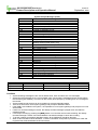
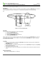
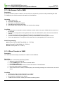
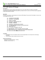
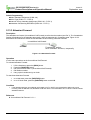
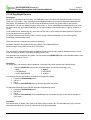
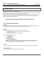
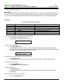
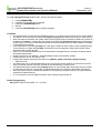
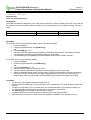
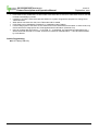
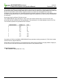
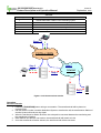
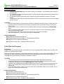
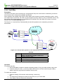
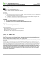
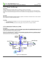
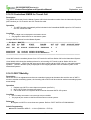
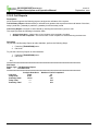
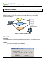
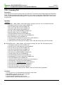
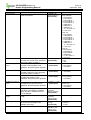
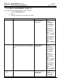
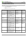
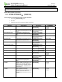
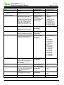
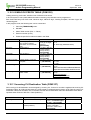
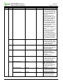
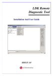
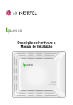
Description
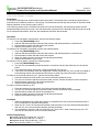
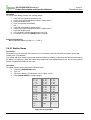
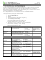
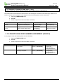
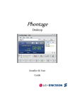
A pre-assigned destination receives incoming calls through the CO Line. The destination (refer to Figure 2.1.1)
can be a Station (Ex. 1), Hunt Group (Ex. 2), VMIB Announcement (Ex. 3) or Net Station(Ex.4). If a destination
station is busy, the incoming call returns a muted ring signal, so the station user can pickup the incoming CO
Call as needed.
Station
PSTN
PSTN or
ISDN
Station
Hunt Group
VMIB announcement
Or Net Station
Figure 2.1.1 Ring Assignment Destination
Operation
Ex. 1 When there’s an incoming CO Call through CO Lines 1 – 8 during Day mode, the Stations 100 –
105 (as available) start to ring instantly. If one of the stations answers the call, other stations stop ringing.
After 9 seconds, if the call is still not answered, station 110 (Attendant) starts to ring.
1.
2.
3.
4.
5.
6.
7.
Set CO Service Type as Normal at the ADMIN 140 menu item.
At ADMIN 144, select CO Line Range 01 – 08 and press FLEX 1 for Day Mode.
Dial 1 for the Station, and enter the station range 100105.
Press 0 to make the stations ring instantly when there is an incoming call.
To save changes, press the [HOLD/SAVE] button.
Press FLEX 1 for Day Mode again without exiting ADMIN 144, and press 1 for the Station again.
Enter Station Range as 110110, and dial 3 as the delay value. Press [HOLD/SAVE] again.
Ex. 2 When there’s an incoming CO Call through CO Lines 1 – 8 during Night mode, the Hunt Group
starts to ring. The ringing station is decided by the Hunt Group type (refer to Ref. A).
1.
2.
3.
4.
5.
Verify the CO Service type is set to Normal at ADMIN 140.
Check if Hunt Group 620 is assigned properly at ADMIN 190.
At ADMIN 144, select CO Line range 01 – 08 and press FLEX 2 (Night Mode).
Dial 2 for the Hunt, and enter Hunt Group Number 620.
To save changes, press the [HOLD/SAVE] button.
2
-20/100/300/300E Version 3.8
Feature Description and Operation Manual
Issue1.0
September, 2008
Ex. 3 When there’s an incoming CO Call through CO Lines 1 – 8 during Weekend mode, the VMIB
announcement played and the line will be released.
1.
2.
3.
4.
5.
Check if CO Service type is set to Normal at ADMIN 140.
Check if VMIB Announcement 01 is recorded properly at the System Attendant Station(refer to Ref.
B).
At ADMIN 144, select CO Line range 01 – 08 and press FLEX 3 for Weekend Mode.
Dial 3 for VMIB, and enter the VMIB Announcement Number 01.
Save the changed setting by pressing the [HOLD/SAVE] button.
Ex. 4 When there’s an incoming CO Call through CO Lines 1 – 8 during Lunch mode, the Net-Station 200
start to ring instantly.
1.
2.
3.
4.
Set CO Service Type as Normal at the ADMIN 140 menu item.
At ADMIN 144, select CO Line Range 01 – 08 and press FLEX 4 for Lunch Mode.
Dial 4 for the Net-Station, and enter the Net-station Number 200.
To save changes, press the [HOLD/SAVE] button.
Condition
Any CO Line Ring Assignment can be programmed for multiple stations, or all stations. And each ring to
station can be delayed by ADMIN programming. The ring assignment is individually applied to ring modes
Day, Night, weekend or On-demand (refer to Ref. C). Every CO Line must be assigned to an Attendant
Station by default (Ref. D).
Reference
A. Hunt Group: 2.6
B. VMIB announcement: 2.11.1
C. Ring Mode: 2.13.8
D. System Attendant: 2.13
Admin Programming
CO Service Type (PGM 140 – FLEX 1)
CO Ring Assignment (PGM 144)
Weekly Time Table (PGM 233)
Hunt Group (PGM 190)
2.1.2 Preferred Line Answer (PLA)
Description
If PLA service is enabled and there are several incoming CO Calls (Transferred, Recalled, Queued, or Normal
Incoming Call) at the same time, the first answered call can be chosen by setting the PLA priority.
NOTE—The default setting for answer order is:
Transferred Call → Recalled Call → Normal Incoming Call → CO Line Queued Call
Operation
If there’s multiple CO Calls ringing at a station and the call is answered at one of the stations, the call with the
highest priority automatically will be answered first.
3
-20/100/300/300E Version 3.8
Feature Description and Operation Manual
Issue1.0
September, 2008
Condition
Automatic Speaker Select feature should be enabled.
The Priority of CO Line for PLA can be changed by Admin Programming.
Admin Programming
Preferred Line Answer (PGM 112 – FLEX 7)
Automatic Speaker Selection (PGM 111 – FLEX 1)
PLA Priority Setting (PGM 173)
2.1.3 Direct Inward Dialing (DID)
Description
This feature allows CO incoming calls to access a specific destination. This feature enables the caller direct
access to a desired Station, Hunt group, VMIB announcement, Speed, or Page, bypassing the Attendant.
There are 3 types of DID Conversions that can be set by ADMIN Programming (ADMIN 143-FLEX 4):
Type 0—In an incoming DID call, select digits which are received by ADMIN Programming; the selected
digits will be converted using DID Conversion type (ADMIN 146 – FLEX 5/FLEX 6).
Type 1—The incoming DID digits are the destination number; there is no conversion.
Type 2—With result of DID Conversion type 1, convert by the Flexible DID table (ADMIN 231) additionally.
Operation
Ex. 1 To make a DID call by DID Digit Conversion(DID type 0), perform the following:
1.
2.
3.
Check if DID Digit Receive Number is set to 3 at ADMIN 146.
Set DID Conversion Type to 0 (using Digit Mask) at ADMIN 143 and press FLEX 4.
Set DID Digit Mask by pressing #1**. The first digit 2 is ignored and second digit 6 is converted to 1
and the last two digits are bypassed. (# : Ignore, *: bypass)
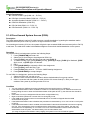
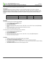
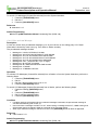
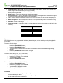
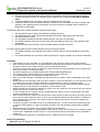
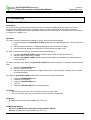
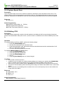
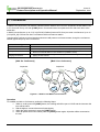
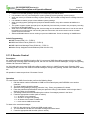
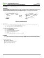
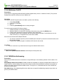
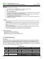
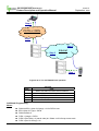
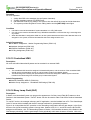
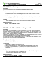
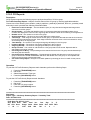
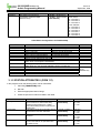
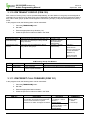
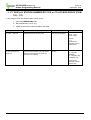
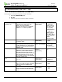
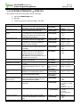
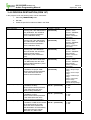
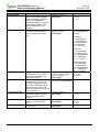
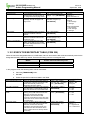
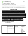
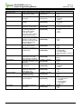
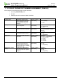
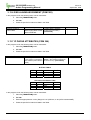
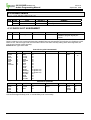
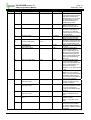
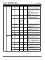
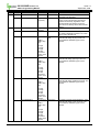
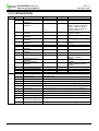
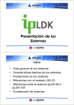
Ex. 2 To make a DID call using the Flexible DID Table(DID type 2), perform the following:
1.
2.
3.
Verify that DID Digit Receive Number is set to 3 at ADMIN 146.
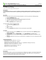
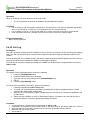
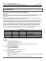
Set DID Conversion Type as 2 (using Flexible DID Table) at ADMIN 143 and press FLEX 4.
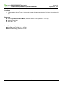
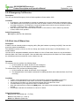
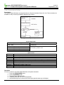
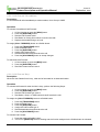
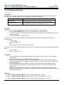
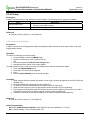
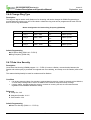
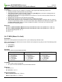
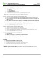
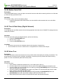
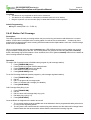
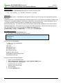
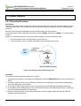
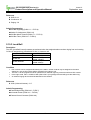
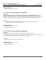
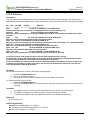
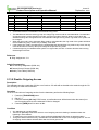
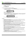
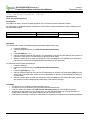
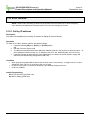
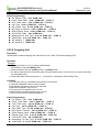
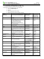
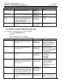
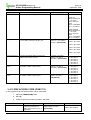
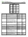
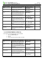
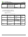
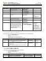
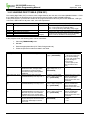
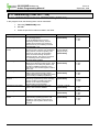
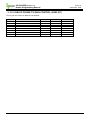
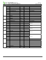
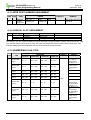
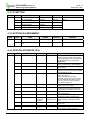
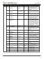
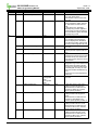
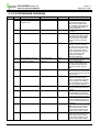
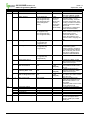
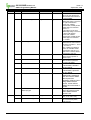
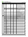
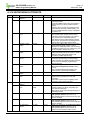
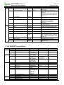
Program Flexible DID Table as shown in the ADMIN 231 Flex DID Conversion Table.
000
001
010
ADMIN 231 FLEX DID CONVERSION TABLE
DAY: Station 200 NIGHT WEEKEND LUNCH
DAY: Hunt 620
NIGHT WEEKEND LUNCH
DAY: Station 129 NIGHT WEEKEND LUNCH
REROUTE
REROUTE
REROUTE
Condition
When a DID (Type 2) is received at a busy station, the call is automatically handled according to the reroute
destination (refer to Flexible DID Table, and Ref. A).Destination of calls handled can be Station, Hunt group,
VMIB announcement, Drop after VMIB announcement, System Speed (refer to Ref. B), Net Station, Station
voice mail box.
If the call is not answered or the number was invalid, the call is routed by DID/DISA Destination.
DID calls to a busy station can be placed on a waiting stage according to admin programming to KTU and
SLT.
Reference
A. Weekly Time Table (PGM223)
B. System Speed Dialing 2.2.8.5
4
-20/100/300/300E Version 3.8
Feature Description and Operation Manual
Issue1.0
September, 2008
Admin Programming
DID Conversion Type (PGM 143 – FLEX 4)
DID Digit Conversion Mask (PGM 146 – FLEX 2)
Automatic Speaker Selection (PGM 111 – FLEX 1)
DID/DISA Destination (PGM 167)
DID Call Wait (PGM 114 – FLEX 17)
DID Restriction (PGM 114 – FLEX 16)
2.1.4 Direct Inward System Access (DISA)
Description
The DISA feature allows incoming CO calls to access a specific destination, bypassing the attendant station.
Compared with DID (refer to Ref. A), there is no digit conversion in DISA.
On accessing an incoming CO Line, the system will give the pre-recorded VMIB announcement (refer to Ref. B)
or dial tone. The caller then is able to dial additional digits to access their desired destination on the system.
Operation
To program DISA Line Assignment, perform the following Steps:
1. Press [TRANS/PGM] and enter 140.
2. Select the CO Line Range to be assigned to DISA Line.
3. Press [FLEX 2], and select the Ring type and press [FLEX 1].
4. To select the Ring Type, press [FLEX 1] for Day, [FLEX 2] for Night, [FLEX 3] for Weekend, [FLEX
4] for Lunch, or [FLEX 5] for On-demand.
5. Dial 1.
6. Press [HOLD/SAVE] to activate the DISA Line Assignment.
7. Press [FLEX 2], select the Ring Type.
8. Press [FLEX 2] then enter 01 – 70 for the VMIB Greeting Assignment.
9. Press [HOLD/SAVE] to accept changes.
To use DISA Line Assignment, perform the following Steps:
1. Select the DISA Line you wish to use.
2. When the tone or announcement is heard, dial the desired station/ hunt group number.
3. After a connection with the system is made, dial the CO Access Code (Ex., 8801) to call again
outside of the system by securing another CO Line.
Condition
You can assign the VMIB announcement instead of the intercom dial tone on a DISA line.
If the DISA Authorization Code is enabled for a DISA Line, a DND warning tone or VMIB announcement is
heard, guiding the user to enter the DISA Authorization Code (refer to Ref. C), the dial tone then should be
heard.
Each DISA Line may be assigned as full-time DISA or Night Mode Only.
Night mode DISA operates as a normal CO Line during Day mode.
If the VMIB announcement number is stored with #, the CO Line will be dropped after the VMIB
announcement is played.
If the DISA Authorization Code is disabled, the permission is determined by CO to CO COS & CO COS (refer
to Ref. D).
If the DISA Authorization Code is enabled, the Authorization Code should be entered to access an outgoing
CO Line. If the Authorization Code is matched with the Authorization Code of the station, the user may
access the CO Line depending on STA COS & CO COS. If the Authorization Code is matched with the
Authorization Code of system, it is determined by COS of Authorization code.
1) If using old System Authorization Code (5 digits), the system CO-to-CO COS will be applied.
5
-20/100/300/300E Version 3.8
Feature Description and Operation Manual
Issue1.0
September, 2008
2) If using Extend System Authorization Code (3~11 digits), the individual Authorization COS will be applied.
(In case of UK or Sweden, user can not access the CO line with station authorization. Only system
authorization code can be permitted)
Reference
A. Direct Inward Dialing (DID): 2.1.3
B. VMIB Announcement: 2.11
C. Authorization Code: 2.5.2
D. Class of Service (COS): 2.5.4
Admin Programming
DISA Line Assignment (PGM 140 – FLEX 2)
DISA Account Code (PGM 141 – FLEX 3)
DISA Retry Counter (PGM 160 – FLEX 4)
CO-to-CO COS Assignment (PGM 166)
Weekly Time Table (PGM 233)
DISA Restriction (PGM 114 – FLEX 10)
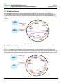
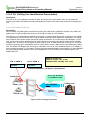
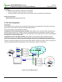
2.1.5 Customer Call Routing (CCR) with VMIB
Description
CCR is the incoming CO Call type of DISA/DID (refer to Ref. A, Ref. B), the user can route the destination by
pressing only one digit. If user presses a certain digit, the corresponding VMIB announcement is played. When
the user presses the desired digit again, call routing is established.
CCR Reroute destination can be assigned by each VMIB announcement. There is three reroute destination.
Busy destination, Error/Time out destination, and No answer destination. Each destination have three type –
Tone, Attendant(Ring Assigned destination), Hunt group. Refer to below condition about CCR reroute
destination
A user also may access the desired destination directly by dialing the Station or Hunt Group number (refer to
Ref. C).
Operation
When a call is answered by a system programmed with CCR, a VMIB announcement should be heard by the
caller. VMIB announcement gives a choice of destination; the caller may select a destination based on the
information presented in the VMIB Announcement.
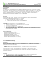
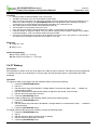
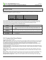
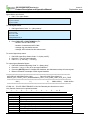
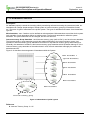
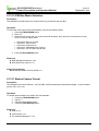
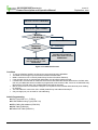
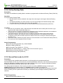
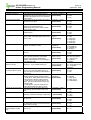
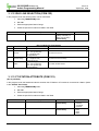
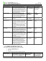
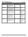
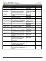
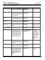
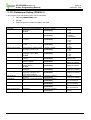
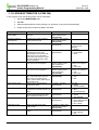
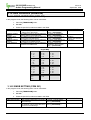
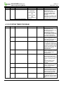
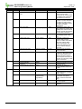
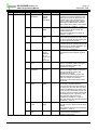
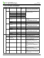
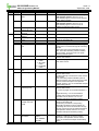
To program the CCR Table as described in Figure 2.1.5, perform the following Steps:
1.
2.
3.
4.
5.
6.
Select CCR Table 01 to match with the VMIB announcement number at ADMIN 228.
Press [FLEX 1] to set the Sales Dept. The Flexible button number should be the same as the dialing
digit number.
Select Destination Type as Hunt Group by dialing 2. Enter the desired Hunt Group Number 620.
Press [FLEX 2] to set the Technical Dept.
Select destination type as VMIB by dialing 2 or 3 and enter Announcement Number 02.
Press [FLEX 10] to set the Operator. Select the destination type as Station by dialing 1 and enter the
desired Station Number 101.
NOTE—If Destination 04 (VMIB Drop) is selected, the call will be dropped after the Announcement is
played.
6
-20/100/300/300E Version 3.8
Feature Description and Operation Manual
Issue1.0
September, 2008
To use DISA CCR, perform the following Steps:
1.
2.
3.
4.
5.
Verify the CO Service Type is set to Normal at ADMIN 140.
Press [FLEX 1].
Verify the DISA Service is set to ON at ADMIN 140.
Press [FLEX 2] (refer to Ref. C).
Set VMIB Message Number to 01 ADMIN 140 and press [FLEX 2].
To use DID CCR, perform the following Steps:
1.
2.
3.
4.
5.
6.
7.
Verify the CO Service Type is set to DID/MSN at ADMIN 140.
Press [FLEX 1].
Verify the DID Digit Receive Number is set to 3 at ADMIN 146.
Set DID Conversion Type as 2 (using Flexible DID Table) at ADMIN 143.
Press [FLEX 4].
Set the Destination Type as 3 (VMIB).
Select Announcement Number 01 for the Flexible DID Table at ADMIN 231.
Condition
To use the CCR feature for DID, VMIB should be assigned for Flexible DID Destination (ADMIN 231).
The CCR feature is only supported for DID and DISA.
If a caller dials a full destination number, the call will be directly routed to the desired destination by the
system numbering plan.
If a caller dials one digit then pauses, the ipLDK system will compare the digit with the CCR Table. If a
matching digit is found on the CCR Table, and the bin number is the same as the VMIB Announcement, the
call will be routed to the programmed destination.
In PGM 228 - CCR table, if a CCR announcement has any valid destination, call can be rerouted to CCR
destination. For example, VMIB announcement 2 is assigned to DISA announcement(PGM 140)
Case 1) For announcement 2, any program is existed in PGM 228, call is routed to CCR destination.
Case 2) For announcement 2, any program is not existed in PGM 228, call is routed to DID/DISA destination.
If Destination is busy, the caller can attempt to redial up to DISA retry count. When the DISA retry count is
over, the call will be routed to CCR Busy reroute Destination.
If the dialed digit is invalid, or user did not dial any digit in proper time, the caller can attempt to redial up to
DISA retry count (PGM 160 – Flex4). When the DISA Retry Counter is exceeded, the call will be routed to
CCR ERROR reroute Destination.
If Destination is no answer, the call will be routed to CCR No Answer reroute Destination.
DISA retry count can be applied by each CCR announcement.
VMIB announcement 01 – 70 may be used for CCR.
Call routing will be operated with previously programmed VMIB announcement.
The maximum CCR depth is 10.
The external user can dial alternate digits while the VMIB announcement is being played or the digits should
be entered within the Inter-digit Time (5 sec) after the announcement is ended.
If the caller does not dial any digits within the Inter-digit Time (5 sec), the call will be routed to the Assigned
Ring Station or disconnected following an error tone.
If a user presses the # button while CCR is in operation, CCR will return to the first step of Operation.
If a user presses the * button while CCR is in operation, CCR will return to the previous step.
The call will be dropped directly after the VMIB announcement if VMIB Drop is selected at the CCR Table.
If a call is routed to System Speed Dial, the call will be routed to the applicable Speed Dial destination. If the
CO Call is assigned System Speed Dial, the routing will be the same as Incoming CO Off-net Call Forward.
Reference
A. Direct Inward Dial (DID): 2.1.3
B. Direct Inward System Access (DISA): 2.1.4
C. VMIB Announcement: 2.11
D. DISA Authorization Code: 2.5.2
E. System Speed Dial: 2.2.8.5
7
-20/100/300/300E Version 3.8
Feature Description and Operation Manual
Issue1.0
September, 2008
Admin Programming
Flexible DID Table (PGM 231)
DID Digit Conversion Table (PGM 146 – FLEX 5/ FLEX 6)
DISA Retry Counter (PGM 160 – FLEX 4)
CCR Inter-digit Timer (PGM 180 – FLEX 15)
Inter-digit Timer (PGM 181 – FLEX 8)
DID/DISA Destination (PGM 167)
Custom Call Routing Table (PGM 228)
2.1.6 CO Line Name
Description
This feature allows the capability to name each CO Line. Stations with an LCD interface screen, including the
Attendant Station, will display the programmed CO Line Name when incoming CO call in place of the default
LINE XXX display (If nation is Turkey, all of incoming and outgoing CO call is displayed line Name).
Condition
This applies to all conditions where the LINE XXX message is displayed. However, SMDR will display the line
number in place of the programmed name (refer to Ref. A).
A CO Line Name can be assigned to each CO Line.
Each CO Line Name can contain up to 12 characters.
If the CO Line Name Display is set to OFF at ADMIN 142 with [FLEX 1] selected, the CO Line Name is not
displayed even if the name is programmed.
Reference
A. Station Message Detail Recording (SMDR): 2.12
Admin Programming
CO Line Name Display (PGM 142 – FLEX 1)
CO Line Name Assignment (PGM 142 – FLEX 2)
2.1.7 Universal Answer (UNA)
Description
If the CO Line is programmed for UNA, any user can pick up incoming CO Calls by dialing the Universal Answer
code 569 (refer to Ref. A), regardless of the pick-up group.
If there are incoming CO Calls, Station B can pick up the call even though Station A and B do not belong to a
pick up group.
Operation
To pick-up a call, perform the following Steps:
1.
2.
3.
4.
Lift the handset or press the [MON] button.
The intercom dial tone should be heard.
Dial 5 6 9 for the Universal Answer code.
The call is connected.
8
-20/100/300/300E Version 3.8
Feature Description and Operation Manual
Issue1.0
September, 2008
Condition
If there isn’t an incoming CO Call, Universal Answer Code is dialed from a station, an error tone will be heard.
If External Night Ringing is set to On, the call is routed to External Page (refer to Ref. B) by LBC1 (refer to Ref.
C).
Reference
A. Refer to ipLDK Installation Manual, Universal Answer Code (PGM 107 – FLEX 4)
B. External Page: 2.8.1
C. Loud Bell: 2.10.3
Admin Programming
Universal Answer (PGM 141 – FLEX 8)
External Night Ring (PGM 160 – FLEX 7)
9
-20/100/300/300E Version 3.8
Feature Description and Operation Manual
Issue1.0
September, 2008
2.2 Outgoing Call Access
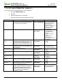
2.2.1 Basic Access
Description
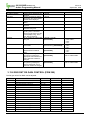
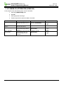
Each station is allowed or denied access based on particular CO Lines or CO Groups. Station users may use
Flexible buttons which are assigned as a {CO} button or {CO Group} button, including the {POOL} and {LOOP}
buttons. According to the Numbering Plan, station users can access individual CO Lines by dialing CO Access
Codes.
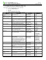
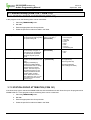
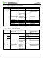
Feature
Idle Line Access
(88 + CO Line
number)
CO Group Access
(8 + CO Group
number)
Description
Automatically selects
an idle CO Line from
the assigned CO
Groups.
Selects an idle CO Line
from the
corresponding CO
Group.
Operation method
Dial the idle Line Access
Number (9), or press a
CO Line button.
Dial the CO Group Access
number and a CO Group
number, or press a CO
Group button.
Access code
8801-8816 (ipLDK-20)
8801–8840 (ipLDK-100)
88001–88200 (ipLDK-300)
88001–88400 (ipLDK-300E)
801-808(ipLDK-20)
801-824(ipLDK-100)
801-872(ipLDK-300/300E)
A user can dial 9 (refer to Ref. A) to access the first idle line in their CO group (refer to Ref. D).
A user can dial 8801 (refer to Ref. B) to access CO Line 001 if it is idle.
A user can dial 801 (refer to Ref. C) to access the first idle CO Line in CO Group 1.
Operation
To access a CO Line from a DKTU, perform the following Steps:
1. Lift the handset or press the [MON] button.
2. Press the desired CO Line, {POOL} button, or {LOOP} button.
OR
3. Dial the individual CO Line Access Code, CO Group Access Code, or the first CO Line Access Code
from the accessible group.
To access a CO Line from a SLT, perform the following Steps:
1.
2.
Lift the handset.
Dial the individual CO Line, CO Group Access Code, or the first CO Line Access Code from the
accessible group.
To access a CO Line Group, perform the following Steps:
1.
2.
3.
Lift the handset.
Press 8 for the CO Group.
Dial the CO Group number (refer to Ref. A)
To assign the {LOOP} button, perform the following Steps:
1.
2.
3.
4.
5.
Press the [TRANS/PGM] button
Press {FLEX}
Press [TRANS/PGM]
Dial 8 4
Press the [HOLD/SAVE] button to accept changes.
10
-20/100/300/300E Version 3.8
Feature Description and Operation Manual
Issue1.0
September, 2008
Condition
When the Override 1st CO Line Group is enabled, the System will search for the next accessible CO group
until a CO Line is available if there is no available CO Line by dialing the CO Line group access code (9 or 0).
An error tone should be heard when a Station is not permitted to access a CO Line, but the Station will still be
able to receive a transferred CO Line call as applicable.
The CO Line choice (Round-robin or Last Choice) is determined by Admin Programming (ADMIN 160-FLEX
3)
If the CO Line is BRI, when a user tries to secure B1 the System can change the CO Line to B2 (if there is a
{B2 CO} button or {LOOP} button).
Unused CO Lines should be assigned to unused CO Group to prevent being accessed by a station.
The first CO Line group (00) is the directed line group and can be used with the {CO Line} button (Private
Line).
Reference
A. Refer to ipLDK Hardware Description and Installation Manual, Access CO in 1st CO Group Code
(PGM 107 – FLEX 12)
B. Refer to ipLDK Hardware Description and Installation Manual, Access Individual CO Code (PGM 107
– FLEX 8)
C. Refer to ipLDK Hardware Description and Installation Manual, Access CO Group Code (PGM 107 –
FLEX 7)
D. CO Line Choice (PGM 160 – FLEX 3, Round Robin/Last Choice)
Admin Programming
CO Line Choice (PGM 160 – FLEX 3)
Inter-digit Timer (PGM 181 – FLEX 8)
CO Line Group Access (PGM 117)
CO Line Group (PGM 141 – FLEX 1)
Override 1st CO Line Group (PGM 161 – FLEX 3)
2.2.2 Call Time Restriction
Description
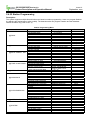
The Call Time Restriction feature is used to restrict outgoing CO call time. In Station programming, the User can
set the Call Cut-Off timer, whereas the call will be disconnected automatically when the timer expires. The called
and called parties will hear a warning tone 15 seconds before the call is disconnected.
Condition
This feature can be assigned on a station-by-station basis, and is applied to just outgoing CO calls.
If the Call Cut Off timer is enabled on a Station, the timer is still applicable when a call is transferred to
another Station.
On the add-on conference, the Call Cut Off timer enabled Station will be restricted to the outgoing CO call
time.
The Call Cut Off timer is not released when the call is placed on hold, or is transferred.
Admin Programming
CO Call Time Restriction (PGM 112 – FLEX3)
Call Cut-Off Timer (PGM 113 – FLEX12)
11
-20/100/300/300E Version 3.8
Feature Description and Operation Manual
Issue1.0
September, 2008
2.2.3 CO Line Queuing
Description
When a Station user receives a busy tone during an attempt to access a CO Line, the user may request a call
back (queue call). The station will receive a call back when the busy CO Line becomes available.
Operation
To activate CO Line Queuing while receiving a busy tone, perform the following Steps:
1.
2.
3.
4.
5.
Press and release the hook-switch if the station is a SLT.
Dial 5 5 6 (refer to Ref. A) or press the [CALL BK] button.
When the confirmation tone is heard, replace the handset.
Once the CO Line becomes idle, the call back ring will be received at the station.
Lift the handset, the CO dial tone should be heard to make a call.
Condition
1. A CO Line may have any number of queues at one time.
2. When the queued CO Line becomes idle or a CO Line becomes available in the group, the oldest
queued station will receive the call back.
3. A station can make only one CO Line queuing request at a time. If the station tries to make another
CO Line queuing, the previous one is canceled and the newer one is activated.
4. If the waiting station is busy and the queued CO Line is available, the available CO Line will be
directed to the next queued idle station.
5. If the waiting station is idle, the queued CO Line will give a call back signal to the station for 15
seconds. If the signal is not received at the station, the queue is canceled and the next station in the
queue will receive the signal.
Reference
A. Message Wait Enable: 2.4.16
Admin Programming
CO Line Queuing (PGM 112 – FLEX 5)
2.2.4 CO Step Call – Analog Only
Description
When a station receives a busy tone after accessing a CO Line, the user can dial a CO Line number which has
the same first digits as the called busy CO Line without dialing the full number.
Operation
To use CO Step Call when receiving a busy tone, perform the following Steps:
1.
2.
Press the [SPEED] button and dial the last digit of the previously called number.
The previous call is terminated and a new call is established.
Condition
CO Flash Timer(Depending on the Public Exchange): it may be necessary to increase this timer in order to use
the CO Step Call Feature.
Admin Programming
CO Flash Timer (PGM 142)
12
-20/100/300/300E Version 3.8
Feature Description and Operation Manual
Issue1.0
September, 2008
2.2.5 Emergency Call Service
Description
The user can dial the Emergency Service Code regardless of lower station COS.
Condition
An emergency call can be dialed by pressing an available CO Line at the station that is assigned to COS 7.
If the dialed number for emergency code is the same as station number or LCR number, the call is operated
according to preference. The preference of programmed dial number which is sent to external CO line is,
LCR table -> Station Number -> Emergency Call code.
When emergency code is the same as station number or LCR number, if COS 7 Station only dials this
number, station call is operated.
Admin Programming
Emergency Service Call (PGM 226)
2.2.6 Hot Line & Warm Line
Description
A station user can instantly make an outgoing call by lifting the handset or pressing the [ICM], if the user has
previously stored the destination.
The destination can be a CO Line or CO Line Group; the function can be setup on a Flexible Button, or at
another Station.
Hot Line can be activated immediately when the Station is in the off-hook state; Warm Line can be activated
after the Warm Line Timer has expired. If the user dials other number prior to the Warm Line Timer expiration,
the call will activate as a normal call, not as a Warm Line call.
Operation
To activate a Hot Line, perform the following Steps:
1. Lift the handset at a station where Hot Line is assigned.
2. The assigned Hot Line feature is immediately activated.
To activate Warm Line, perform the following Steps:
1. Lift the handset at a station where Warm Line is assigned.
2. The assigned Warm Line feature is activated if no dialing has been done while the Warm Line Timer
is running.
Condition
A station can be assigned Hot Line or Warm Line with Admin Programming (ADMIN 113-FLEX 7).
If there is no Flexible Button at the station, the number is operated as a Speed Dial Number.
The set value of the Warm Line Timer should be less than that of the Dial Tone Timer.
A Flexible Button may be assigned as an Idle Line Selection button.
When lifting the handset or pressing the [MON] button, the system will be activated as a predefined button is
pressed.
It is possible to activate Hot Line/Warm Line at an SLT station.
Admin Programming
Warm Line Timer (PGM 182 – FLEX 8)
Warm Line (PGM 113 – FLEX 7)
Idle Line Selection (PGM 122)
13
-20/100/300/300E Version 3.8
Feature Description and Operation Manual
Issue1.0
September, 2008
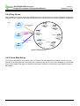
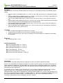
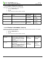
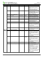
2.2.7 Least Call Routing (LCR)
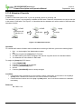
Description
LCR is a system programmable feature that automatically selects the least expensive available route when an
outgoing CO call is made. This programming eliminates the necessity for the user to dial the access code of the
least expensive carrier. There are three ways to activate LCR:
Internal LCR - If dialed digits are matched with an internal LCR code, the system will secure a CO Line from
the programmed CO Group and send the modified digits according to LCR programming.
Loop LCR - When dialing the first accessible CO Group Code (9 or 0), or pressing the [Loop] button, if the
dialed digits match with a COL LCR code, the system will secure a CO Line from the programmed CO Group
and send the modified digits according to LCR programming.
Direct CO LCR - After dialing a CO Line or CO group code (9 or 0, depending on the nation you are calling
from), or pressing a CO Line or CO group button, LCR can be activated. If the dialed digits are matched with
a COL LCR code, the system will secure a CO Line from the programmed CO group and send the modified
digits according to LCR programming.
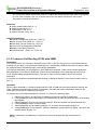
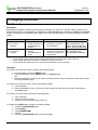
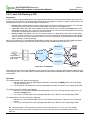
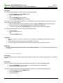
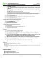
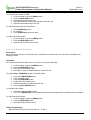
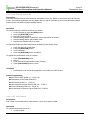
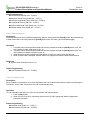
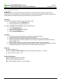
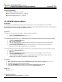
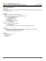
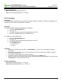
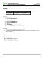
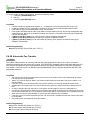
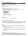
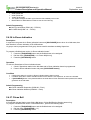
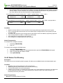
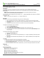
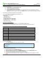
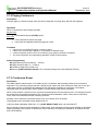
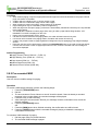
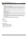
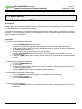
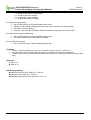
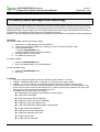
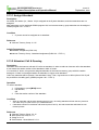
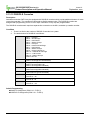
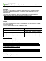
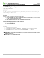
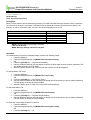
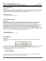
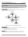
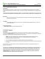
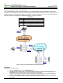
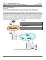
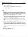
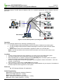
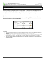
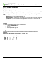
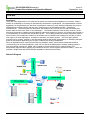
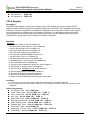
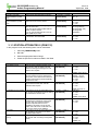
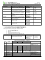
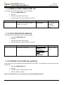
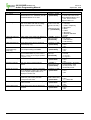
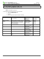
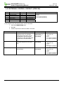
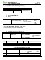
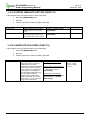
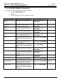
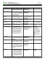
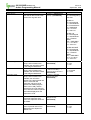
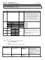
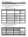
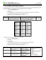
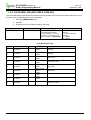
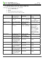
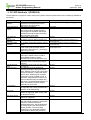
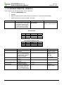
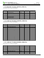
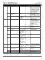
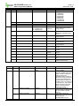
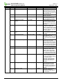
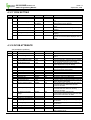
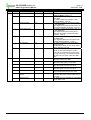
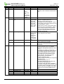
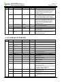
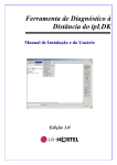
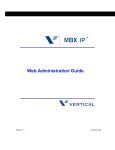
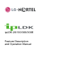
When a user selects a CO Line and dials a destination number, the system checks the LCR programming and
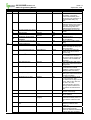
sends the call according to the least cost route according to the ADMIN program (Figure 2.2.7).
001
Network A
002
Caller dials ‘9’
+ phone number
(850 1234)
Network
Network B
008
Network C
Figure 2.2.7 LCR Routing
(850 1234)
Assuming the LCR code is 9, the Network A (001) is least cost during the daytime, and Network B (002) is least
cost during the night. The Caller dials the same number and the System automatically routes it through the least
cost network.
Operation
To activate Internal LCR, perform the following:
1. Dial the internal LCR Code after lifting the handset, or pressing the [MON] button (on-hook dialing
can also activate LCR).
2. It is an internal LCR Code if the code is programmed with internal or both in the Leading Digit Table.
To activate Loop LCR, perform the following:
1. Dial COL LCR code after dialing the first accessible CO Line or CO Group access code (0 or 9), or
press the [Loop] button.
2. It is a COL LCR code if the code is programmed with COL or BOTH in the Leading Digit Table.
To activate Direct CO LCR, perform the following:
1. Dial the COL LCR code after dialing a CO or CO Group Access code, or press a CO or CO Group
button.
2. It is a COL LCR code if the code is programmed with COL or BOTH in the Leading Digit Table.
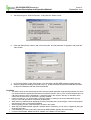
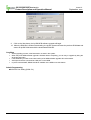
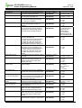
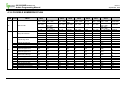
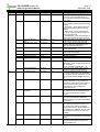
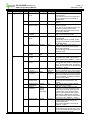
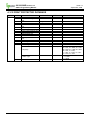
Ex. 1 Add Prefix Digit—The long distance call access code starts with 0 (i.e., 02, 031, 051); if a cheaper
carrier exists, the user can access it with the carrier access code 082 and the long distance access code
without 0.
14
-20/100/300/300E Version 3.8
Feature Description and Operation Manual
Issue1.0
September, 2008
ipLDK system administrator wants to use this cheaper carrier for all long distance calls (i.e., dial
0314502628, 082314504628).
ADMIN 220
LCR MODE
M01, M02, M11, M12
(LOOP LCR enabled)
ADMIN 221 (LDT)
Bin 000
LCR TYPE: COL
LCR CODE: 0
DMT: 00 00 00
ADMIN 222 (DMT)
Bin 00
Remove Position: 01
Remove Number: 01
Add Position: 01
Add Digit: 082
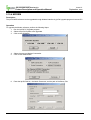
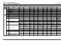
Ex. 2 Select CO Group—ipLDK system is connected with two carriers (one carrier is carrier A, the other
carrier is carrier B). Carrier B is used for international calls, and Carrier A is used for all other calls. The
international call access code is 001.
ipLDK system administrator wants to program Carrier B to be used for only international calls.
ADMIN 141
Set CO Lines from the carrier ‘A’ to CO group 1
Set CO Lines from the carrier ‘B’ to CO group 2
ADMIN 220
LCR MODE
M01, M02, M11, M12
(LOOP LCR enabled)
ADMIN 117
Enable access CO group
01, 02
ADMIN 221 (LDT)
Bin 000
LCR TYPE: COL
LCR CODE: 001
DMT: 00 00 00
ADMIN 161-3
Override 1st CO Group :
OFF
ADMIN 222 (DMT)
Bin 00
Co Group: 02
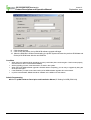
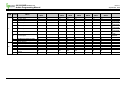
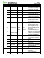
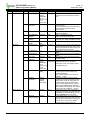
Ex. 3 Make another CO Access Code—ipLDK system has VOIP CO Lines and normal CO Lines; system
administrator wants to access VOIP CO using code 7, and access normal CO Lines using code 9 (as the
default CO Access Code).
ADMIN 106
Remove / change numbering plan which starts with ‘7’
ADMIN 141
Set normal CO Lines to CO group 1
Set VOIP CO Lines to CO group 2
ADMIN 220
LCR MODE
M02, M12, M13
(Internal LCR enabled)
ADMIN 117
Enable access CO group 01, 02
ADMIN 221 (LDT)
Bin 000
LCR TYPE : INT
LCR CODE : 7
DMT : 00 00 00
ADMIN 161-3
Override 1st CO Group : OFF
ADMIN 222 (DMT)
Bin 00
Remove Position : 01
Remove Number : 01
Co Group : 02
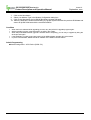
Ex. 4 Password for specific dial number—The international access code is 001; system administrator
allows international calls by only those users who know the system password.
ADMIN 220
LCR MODE
M12, M13
(LOOP/CO LCR enabled)
ADMIN 221 (LDT)
Bin 000
LCR TYPE: COL
LCR CODE: 001
DMT: 00 00 00
Check Password: ON
15
ADMIN 222 (DMT)
Bin 00
Co Group: 01
-20/100/300/300E Version 3.8
Feature Description and Operation Manual
Issue1.0
September, 2008
Condition
There are 6 LCR modes. The mode is determined by ADMIN 220 – FLEX 1.
- LCR Access Mode 00 (M00): LCR call is disabled.
The leading digits can be duplicated. FLEX 2 and the DMT index make each entry unique.
The Leading Digit table is sorted by leading digits, FLEX 2 in LDT (INT, COL, BOTH) and DMT index.
Internal LCR is applied if the dialed digits are matched with one of leading digits and FLEX 2 is INT or BOTH.
Loop LCR is applied if the dialed digits are matched with one of leading digits and FLEX 2 is COL or BOTH.
Direct CO LCR is applied if the dialed digits are matched with one of the leading digits and FLEX 2 is COL or
BOTH, and the secured CO Line belongs to the programmed CO Group in DMT.
To work Loop LCR and Direct CO LCR differently with the same leading digits, there should be a leading digit
entry for loop LCR prior to the leading digits for direct CO LCR. It is possible if the DMT index for loop LCR is
smaller than the DMT index for direct CO LCR.
While direct CO LCR is applied to ISDN CO, an ISDN Information message with called party IE, which
includes only the numbering plan and numbering type, is sent to the network when a user dials a digit. It is for
the network not to disconnect the line.
For direct CO LCR, leading digits should be programmed in consideration with the dial tone time provided by
the Network.
Direct CO LCR does not use an alternative DMT index if a CO Line is already accessed.
LCR always has the higher precedence than the flexible numbering plan table.
LCR can be applied in the following instances:
- Dialing after accessing a CO Line by dialing a CO Line access code (0 or 0) only.
- Dialing after accessing a CO Line by pressing the {LOOP} button.
- Dialing without accessing a CO Line.
- Speed Dial.
- Off-net Call Forward
- Redial (if the previous call is LCR applied).
- ACNR (If the call is LCR applied when activating ACNR)
Any leading digit string at the LDT table can be a sub-string of another leading digit string such as 012 and
0123.
Capacity for LCR Table:
- 3 Day Zones
- 3 Time Zones
Number of ‘Dialed Code Bins’: 250 bins
Number of ‘Modification Code Bins’: 100 bins
Maximum number of ‘Dialed digits’: 12 digits
Maximum number of ‘Added digits’: 25 digits
Alternative DMT index: 1EA
Admin Programming
LCR Attributes (PGM 220)
Leading Digit Table (PGM 221)
Digit Modification Table (PGM 222)
LCR Table Initialization (PGM 223)
16
-20/100/300/300E Version 3.8
Feature Description and Operation Manual
Issue1.0
September, 2008
2.2.8 Memory Dialing
2.2.8.1 Auto Call Number Redial (ANCR)
Description
If Call destination is busy or no answer, redialing is operated repeatedly within the ACNR retry counter. The
system will retry the number based on programming with appropriate pauses in between dialing (default = 3
times).
Operation
To use ACNR while receiving a busy/no answer indication on a CO Line, perform the following Steps:
1.
2.
3.
4.
Press the [REDIAL] button.
Replace the handset or go on-hook.
The system will automatically retry the call at programmed intervals.
When the called party answers, lift handset,
OR
5. Press the [MUTE] button to make the call.
To cancel ACNR, perform the following Steps:
1. Press the flashing [REDIAL] button,
OR
2. Lift the handset,
OR
3. Press the [MUTE] button while a CO Line is accessed to cancel ACNR.
Condition
1. A DKTU that doesn't have a [REDIAL] button, should be programmed with a [REDIAL] Flexible
Button to use ACNR:
2. [TRANS/PGM] + FLEX + [TRANS/PGM] + 9 7 + [HOLD/SAVE] (2 or 8 Button only)
3. The analog CO Lines in the system should be equipped with Call Progress Tone detection Units
(CPTU).
4. When a predefined CO Line is busy in ACNR mode, an available CO Line in the same group will be
secured.
Admin Programming
ACNR Pause Timer (PGM 180 – FLEX 10)
ACNR Delay Timer (PGM 180 – FLEX 8)
ACNR Tone Detect Timer (PGM 180 – FLEX 13) – applicable to analog CO Line only
ACNR No Answer Timer (PGM 180 – FLEX 9)
ACNR Retry Counter (PGM 180 – FLEX 11)
ACNR Tone Cadence (PGM 423)
2.2.8.2 Last Number Redialing
Description
The last dialed number on a CO Line can be stored (up to 32digits) in the station's Last Number Redial buffer.
The user may select to redial the last number dialed on the system. Each DKTU with an LCD panel in the
system has 10 individual last dialed number directory locations.
17
-20/100/300/300E Version 3.8
Feature Description and Operation Manual
Issue1.0
September, 2008
Operation
To use Last Number Redial at a DKTU, perform the following Steps:
1. Lift the handset or press the [MON] button.
2. Press the [REDIAL] button,
OR
3. Press the [SPEED] button and dial *.
4. Press the [HOLD/SAVE] button to accept.
To use one of the recently dialed numbers in the Last Number Directory by scrolling at a DKTU with an LCD
panel, perform the following Steps:
1.
2.
When the last dialed number is displayed, press the [UP] or [DOWN] button to find the desired
phone number (up to 10 last dialed numbers can be stored in the directory).
To make a call, press the [HOLD/SAVE] button when the phone number is displayed.
To use Last Number Redial at an SLT, perform the following Steps:
1.
2.
3.
Lift the handset.
Dial 5 5 2 (refer to Ref. A),
OR
Press the [REDIAL] button.
Condition
When the used CO Line is busy, an idle CO Line in the group is accessed and the last dialed number is
dialed.
The last dialed number directory allows duplicated phone numbers.
If you use Last Number Redial while the Auto-redial is activated, the auto-redial is canceled.
Reference
A. Refer to ipLDK Hardware Description and Installation Manual, SLT Last Speed Dial Code (PGM 106
– FLEX 12)
2.2.8.3 Save Number Redialing
Description
Any dialed number can be saved temporarily and used at any time. This number is saved until a new number is
stored.
Operation
To save a number in the Save Number Redial buffer from a DKTU, perform the following Steps:
1. Press the [SPEED] button twice, while on a conversation with an external party.
2. Replace the handset or go on-hook.
To dial a number from the Save Number Redial buffer from a DKTU, perform the following Steps:
1. Lift the handset or press the [MON] button.
2. Press the [SPEED] button.
3. Press the # button.
18
-20/100/300/300E Version 3.8
Feature Description and Operation Manual
Issue1.0
September, 2008
Condition
1. When the used CO Line is busy, an idle CO Line in the group is accessed and the saved number is
dialed.
2. The stored save number is not deleted when the system power is OFF.
3. If you press [SPEED] button twice after accessing a CO Line and dialing, then pause, the save
number redial bin will be erased.
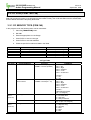
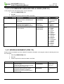
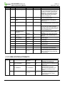
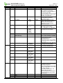
2.2.8.4 Station Speed Dialing
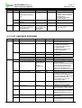
Description
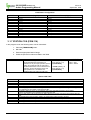
A DKTU user can store up to 100 frequently used station numbers to Station Speed Bin (000 – 099). Station
numbers consisting of up to 24 digits including pauses, Flash commands, pulse-to-tone switchover, and nodisplay characters (pause is automatically inserted after a flash).
MODEL
ipLDK-20
ipLDK-100
ipLDK-300
ipLDK-300E
Speed dial of system
500
1500
3000
5000
Operation
To make a call using Station Speed Dial from a DKTU, perform the following Steps:
1. Lift the handset or press the [MON] button.
2. Press the [SPEED] button.
3. Dial the Station Speed Dial bin (000 – 099).
To store Station Speed Dial numbers from a DKTU, perform the following Steps:
1.
2.
3.
4.
5.
6.
7.
8.
9.
Press the [TRANS/PGM] button.
Press the [SPEED] button.
Dial the Station Speed Dial bin (000 – 099).
If desired, press the CO Line or Group button.
Dial the desired telephone number, including these special codes:
[CALLBK] – Insert Pause
* key – If stored as the first digit, its function is Display Security. Otherwise, its function is Pulse to DTMF
Switchover.
[DND/FOR] – If CO Dial Tone Detect (refer to Ref. A) is ON and it is stored as the first or second digit,
and the accessed CO Line is behind the PBX mode, its function is Dial Tone Detect. Otherwise, its
function is Pause.
[FLASH] – Inserts a Flash into the speed number.
If the accessed CO Line is analog, its function is Flash to PX (or PBX).
If the accessed CO Line is ISDN line (refer to Ref. B) and it is stored as the first digit, it makes the
remaining digits sent with envelope information not in the Calling Party Number IE but in keypad facility
IE.
Press the [HOLD/SAVE] button.
If desired, enter the name (max. 16 characters) using the 2-digit code for each character.
Press the [HOLD/SAVE] button.
To store continuously, repeat this procedure from Step 3.
To delete a Station Speed Dial bin, perform the following Steps:
1.
2.
3.
4.
5.
Press the [TRANS/PGM] button.
Press the [SPEED] button.
Dial the Speed Dial bin number to be erased.
Press the [HOLD/SAVE] button.
The stored Speed Dial number should be erased from the speed bin.
19
-20/100/300/300E Version 3.8
Feature Description and Operation Manual
Issue1.0
September, 2008
To display and enter a Speed Dial bin by scrolling, perform the following Steps:
1.
2.
3.
4.
Press the [TRANS/PGM] button.
Press the [SPEED] button.
Dial the Speed Dial bin number.
Press the [UP] or [DOWN] key to display the next/previous Speed Dial number.
To store Station Speed Dial numbers from a SLT, perform the following Steps:
1.
2.
3.
4.
5.
Lift the handset.
Dial the Speed Dial program code 5 5 5 (refer to Ref. C).
Dial the Speed Dial bin number (000 – 099).
Dial the desired phone number (up to 24 digits).
Press and release the hook-switch.
To make a call using Station Speed Dial from a SLT:
1. Lift the handset.
2. Dial the Speed Dial access code 5 5 8 (refer to Ref. D).
3. Dial the Station Speed dial bin (000 – 099).
To delete a Station Speed Dial from a SLT:
1.
2.
3.
4.
Lift the handset.
Dial the Speed Dial access code 5 5 5 (refer to Ref. C)
Dial the appropriate Station Speed Dial bin (000 - 099).
Press and release the hook-switch.
Condition
1. CPTU should be installed to detect a dial tone.
2. The Station Speed Dial is secured in data protect mode when the power is OFF.
3. There can be a maximum of 24 digits in a Station Speed Dial number including special digits and
Function codes.
4. If you dial an empty station Speed dial bin, an error tone will be heard.
5. If you select a CO Line before dialing a Speed Dial bin number, the selected CO Line is used even
though there is a programmed CO Line in the Speed Dial bin number.
6. If the speed dial is programmed to access a specific CO line and the line access by the speed dial is
busy, the system seizes another Co line registered in the same CO line group.
Reference
A. CO Dial Tone Detect (ADMIN 160 – FLEX 6)
B. ISDN Line: 2.14
C. Refer to ipLDK Hardware Description and Installation Manual, Speed Dial Program Code (ADMIN
106 – FLEX 12)
D. Refer to ipLDK Hardware Description and Installation Manual, Speed Dial Access Code (ADMIN 106
– FLEX 15)
Admin Programming
Speed Dial Access (PGM 112 - FLEX 9)
CO Dial Tone Detect (PGM 160 – FLEX 6)
20
-20/100/300/300E Version 3.8
Feature Description and Operation Manual
Issue1.0
September, 2008
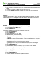
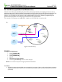
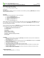
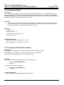
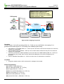
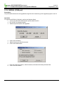
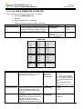
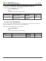
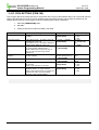
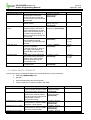
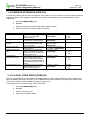
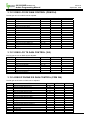
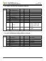
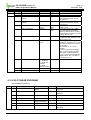
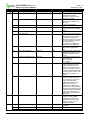
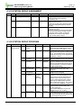
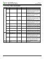
2.2.8.5 System Speed Dialing
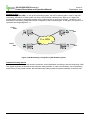
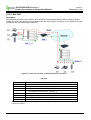
Description
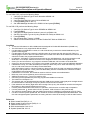
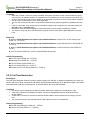
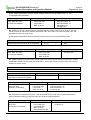
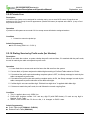
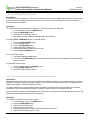
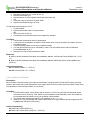
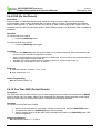
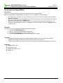
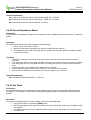
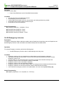
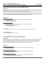
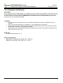
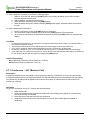
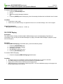
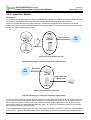
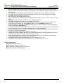
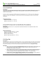
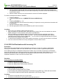
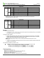
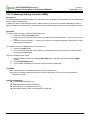
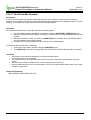
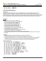
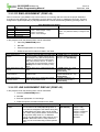
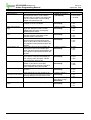
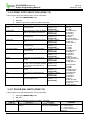
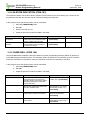
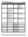
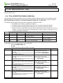
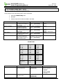
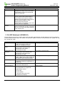
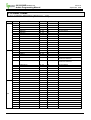
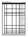
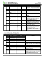
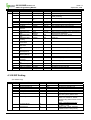
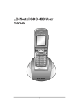
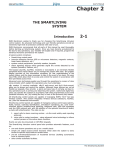
The System Speed Dial bins are programmed by the System Attendant (Figure 2.2.8.5). These numbers are
available for easy access by all stations allowed in the system.
Figure 2.2.8.5 System Speed Dial
System Speed Dial
Speed Dial Range
2000 – 2199
2200 – 2499 (ipLDK-20)
2200 – 3499 (ipLDK-100)
2200 – 4999 (ipLDK-300)
2200 – 6999 (ipLDK-300E)
Description
Unrestricted
Restricted by Station COS
System COS
COS 1
COS 2
COS 3
COS 4
COS 5
COS 6
COS 7
COS 8
COS 9
COS 10
COS 11
There is no restriction to dial.
Monitored by Exception Table A
Monitored by Exception Table B
Monitored by Exception Table A & B
Long distance call is not allowed; the dialed digits can be longer than 7 digits.)
Long distance call is not allowed; only max. 7 digits may be dialed.
Only intercom, paging and emergency call are allowed; no dialing allowed on CO Lines.
Monitored by Exception Table C
Monitored by Exception Table D
Monitored by Exception Table C & D
Monitored by Exception Table A, B, C & B
Operation
To store a number in a System Speed Dial from the System Attendant:
1.
2.
3.
4.
5.
Press the [TRANS/PGM] button.
Press the [SPEED] button.
Dial the System Speed Dial bin.
If desired, press the CO Line or Group button.
Dial the desired phone number and include these special codes (up to 24 digits).
21
-20/100/300/300E Version 3.8
Feature Description and Operation Manual
6.
7.
8.
9.
Issue1.0
September, 2008
[CALLBK] – Insert Pause
* key – If stored as the first digit, its function is Display Security. Otherwise, its function is Pulse to DTMF
Switchover.
[DND/FOR] – If CO Dial Tone Detect (refer to Ref. A) is ON and it is stored as the first or second digit,
and the accessed CO Line is behind the PBX mode, its function is Dial Tone Detect. Otherwise, its
function is Pause.
[FLASH] – Inserts a Flash into the speed number.
If the accessed CO Line is analog, its function is Flash to PX (or PBX).
If the accessed CO Line is ISDN line (refer to Ref. B) and it is stored as the first digit, it makes the
remaining digits sent with envelope information not in the Calling Party Number IE but in keypad facility
IE.
Press the [HOLD/SAVE] button.
If desired, enter the name (up to 16 characters) by dialing 2-digits for each character.
Press the [HOLD/SAVE] button.
To store continuously, repeat this procedure from Step 3.
To make a call using System Speed Dial from a DKTU:
1. Lift the Handset or press the [MON] button.
2. Press the [SPEED] button.
3. Dial the System Speed Dial bin.
To make a call using System Speed Dial from a SLT:
1. Lift the handset.
2. Dial the Speed Dial access code 5 5 8 (refer to Ref. C).
3. Dial the System Speed Dial bin.
Condition
1. The CPTU should be installed for dial tone detect.
2. System Speed Dial is restricted by Station COS.
3. There can be a maximum of 24 digits in a System Speed Dial number including other applicable
digits and special function codes.
4. If you dial an empty system speed bin, an error tone will be heard.
5. If you select a CO Line before dialing a System Speed Dial bin number, the selected CO Line is used
regardless of if there is a programmed CO Line in the System Speed Dial bin number.
6. If the speed dial is programmed to access a specific CO line and the line access by the speed dial is
busy, the system seizes another Co line registered in the same CO line group.
7. If all CO Lines in the group are busy, a busy tone indication should be heard when attempting to
access a System Speed Dial number.
8. System Speed Dial numbers are protected when the system is powered OFF.
Reference
A. CO Dial Tone Detect (ADMIN 160 – FLEX 6)
B. ISDN: 2.14
C. Refer to ipLDK Hardware Description and Installation Manual, Speed Dial Access Code (ADMIN 106
– FLEX 15)
Admin Programming
Speed Dial Access (PGM 112 – FLEX 9)
System Speed Zone (PGM 232)
CO Dial Tone Detect (PGM 160 - FLEX 6)
22
-20/100/300/300E Version 3.8
Feature Description and Operation Manual
Issue1.0
September, 2008
2.2.9 Private Line
Description
CO Lines in the system can be assigned for exclusive use by one or more DKTU users. Private lines are
assigned to CO Line Group 00 and an appearance (Flexible CO button) is required at the DKTU. (Loop or Pool
keys cannot be used.)
Operation
A private line will operate as a normal CO Line except access is limited to assigned stations.
Condition
1. Private line cannot be picked up.
Admin Programming
CO Line Group (PGM 141 – FLEX 1)
2.2.10 Dialing Service by Prefix code (for Ukraine)
Description
When a user dials the number, a system checks the prefix code and then, if it matched with the prefix code,
the call is made by the table correspond to prefix code.
Operation
1. A user dials the co access code and he hears the dial tone from the system.
2. If a user dials, a System analyzes the dialed digit according to Prefixed Table related to CO line.
3. If it matched the prefix code and sending complete option is OFF, the Setup message is made by the
table corresponds to prefix code.
4. If it matched the prefix code and sending complete option is ON, the Setup message is made by the
table corresponds to prefix code after a user dials max digits.
5. If a Max digit is not same as Max digit, “Enblock inter digit timer” is applied within Max digit.
6. If it does not match the prefix code, the call follows the normal outgoing flow.
Condition
1. This is applied about only ISDN line.
2. Prefix code includes number ‘0~9’ and any digit ‘D’.(with DND button). D used as any digit in
Masked Prefix Table.
3. When a user seizes the CO line to dial, it is changed to BUSY state.
Admin Programming
Prefix Table Index (PGM143 - FLEX16)
Enblock Prefix Table (PGM 205)
23
-20/100/300/300E Version 3.8
Feature Description and Operation Manual
Issue1.0
September, 2008
2.3 Rerouting
2.3.1 Call Forward
Description
A Station User can forward calls to any Station, Station Group, or VMIB in the system by activating feature
codes. There are several types of Call Forwarding: Unconditional, Busy, No answer, Busy/No Answer,
Unconditional Station Off-Net Call Forward, No Answer Station Off-Net Call Forward, Unconditional Station OffNet Call Forward with Tel Number, No Answer Station Off-Net Call Forward with Tel Number, Incoming CO OffNet Call Forward, and Follow Me Call Forward.
Operation
To activate Call Forward, follow Operation directions in each sub-heading for this section.
To program Call Forward to a Flexible Button, perform the following:
1.
2.
3.
4.
Press the [TRANS/PGM] button.
Press the flexible button to be assigned.
Press the [DND/FWD] button.
Assign the Call Forward type:
1 = Call Forward, Unconditional
2 = Call Forward, Busy
3 = Call Forward, No Answer
4 = Call Forward, Busy/No Answer
5 = Unconditional Station Off-Net Call Forward
6 = No Answer Station Off-Net Call Forward
7 = Incoming CO Off-Net Call Forward
# = Deactivation Forward
5. Dial the destination that will receive the call.
6. Press the [HOLD/SAVE] button.
To deactivate Call Forward, perform the following Steps:
1. Lift the handset or press the [MON] button.
2. Press the [DND/FOR] button.
3. Press the # key (Call Forward cancel code).
Condition
1. To use Call Forward, a Station should be activated in Admin Programming.
Admin Programming
Allow Off-Net Call Forward (PGM 111 – FLEX18)
Authorization Code Table (PGM 227)
24
-20/100/300/300E Version 3.8
Feature Description and Operation Manual
Issue1.0
September, 2008
2.3.1.1 Call Forward, Unconditional
Description
A user forwards all calls immediately to another station, Hunt Group or VMIB.
Operation
To activate Unconditional Call Forward:
1.
2.
3.
4.
5.
Lift the Handset or press the [MON] button.
Press the [DND/FOR] button.
Dial the Call Forward code 1.
Dial Station or Group pilot number to receive the calls.
Replace the handset and go on-hook.
To assign {CALL FORWARD} button at a flexible button:
1.
2.
3.
4.
5.
6.
Press the [TRANS/PGM] button.
Press a flexible button.
Press the [DND/FOR] button.
Assign Call Forward type 1.
Dial the destination that will receive the call.
Press the [HOLD/SAVE] button to accept changes.
To deactivate Call Forward:
1. Lift the handset or press the [MON] button.
2. Press the [DND/FOR] button.
3. Dial Call Forward cancel code #.
2.3.1.2 Call Forward, Busy
Description
When the User Station line is busy, calls can be forwarded to an alternate location.
Operation
To activate call forward for when the line is busy, perform the following Steps:
1.
2.
3.
4.
Lift the handset or press the [MON] button.
Press the [DND/FOR] button.
Dial the Call Forward type code 2.
Dial Station, Group, or VMIB number that will receive the call.
To assign the {CALL FORWARD} button at a flexible button:
1.
2.
3.
4.
5.
6.
Press the [TRANS/PGM] button.
Press a flexible button.
Press the [DND/FOR] button.
Assign the Call Forward type 2.
Dial the destination that will receive the call.
Press the [HOLD/SAVE] button.
To activate Call Forward:
1. Press the assigned flexible button.
2. The LED of [DND/FOR] button is flashing and the function assigned to the flexible button is activated.
25
-20/100/300/300E Version 3.8
Feature Description and Operation Manual
Issue1.0
September, 2008
To activate Call Forward to VMIB:
1.
2.
3.
4.
5.
Lift the handset or press the [MON] button.
Press the [DND/FOR] button.
Dial the Call Forward code (1-4).
Dial VMIB selection code number that will receive the call.
Replace the handset and go on-hook.
To deactivate Unconditional Call Forward:
1. Press [DND/FOR] button.
2. Go off-hook.
3. Press [DND/FOR] button and dial #.
To deactivate Call Forward:
1. Lift the handset or press the [MON] button.
2. Press the [DND/FOR] button.
3. Dial the Call Forward cancel code #.
2.3.1.3 Call Forward, No Answer
Description
When the station user does not answer within a predetermined amount time, the call can be forwarded to an
alternate location.
Operation
To activate call forward for when there is no answer, perform the following:
1.
2.
3.
4.
Lift the handset or press the [MON] button.
Press the [DND/FOR] button.
Dial a Call Forward type code 3.
Dial Station, Group or VMIB number to receive the call.
To assign {CALL FORWARD} button at a flexible button:
1.
2.
3.
4.
5.
6.
Press the [TRANS/PGM] button.
Press a flexible button.
Press the [DND/FOR] button.
Assign the Call Forward type 3.
Dial the destination that will receive the call.
Press the [HOLD/SAVE] button.
To activate Call Forward:
1. Press the assigned flexible button.
2. The LED of [DND/FOR] button is flashing and the function assigned to the flexible button is activated.
To deactivate Call Forward:
1. Lift the handset or press the [MON] button.
2. Press the [DND/FOR] button.
3. Dial Call Forward cancel code #.
Admin Programming
Call Forward No Answer Timer (PGM 181 – FLEX 1)
26
-20/100/300/300E Version 3.8
Feature Description and Operation Manual
Issue1.0
September, 2008
2.3.1.4 Call Forward, Busy/No Answer
Description
A User can direct the System to re-route calls to another station, group or VMIB when the Station is busy and/or
does not answer in a predefined 'No Answer' time. Incoming CO Lines, transferred CO Lines, and ringing
Intercom calls are forwarded.
Operation
To activate call forward, when the line is busy or not answer, perform the following:
1.
2.
3.
4.
Lift the handset or press the [MON] button.
Press the [DND/FOR] button.
Dial the Call Forward type code 4.
Dial Station, Group or VMIB number that will receive the call.
To assign {CALL FORWARD} button at a flexible button:
1.
2.
3.
4.
5.
6.
Press the [TRANS/PGM] button.
Press a flexible button.
Press the [DND/FOR] button.
Assign the Call Forward type 4.
Dial the destination that will receive the call.
Press the [HOLD/SAVE] button.
To activate Call Forward:
1. Press the assigned flexible button.
2. The LED of the [DND/FOR] button should be flashing and the function assigned to the flexible button
will be activated.
To deactivate Call Forward:
1. Lift the handset or press the [MON] button.
2. Press the [DND/FOR] button.
3. Dial Call Forward Cancel Code #.
2.3.1.5 Call Forward, Station Off-net (Unconditional, No answer)
Description
Stations allowed call forward access can forward intercom and transferred CO Line calls to a directory number
(telephone number) outside of the system. When a call is received, the system will access an outgoing CO Line
and dial the telephone number entered by the user.
If a station assigned off-net call forward receives a call from an internal and/or external caller, the call will be
forwarded to off-net unconditionally (Code 5) or after No Answer Ring timer is expired (Code 6).
Note that if both incoming CO and outgoing CO are analog line, the system will automatically disconnect the call
after the Unsupervised Conference Timer has expired.
Operation
To activate unconditional Off-Net Call Forward:
1.
2.
3.
4.
5.
6.
Lift the handset or press the [MON] button.
Press the [DND/FOR] button.
Dial the Call Forward code 5.
Seize a CO Line, if required.
Dial the Speed Dial bin number with the desired phone number.
Replace the handset and go on-hook.
27
-20/100/300/300E Version 3.8
Feature Description and Operation Manual
Issue1.0
September, 2008
To activate no answer off-net call forward:
1.
2.
3.
4.
5.
6.
Lift handset or press [MON] button.
Press [DND/FOR] button.
Dial Call Forward Code 6.
Seize a CO Line, if required.
Dial a speed bin number with the desired phone number.
Replace the handset and go on-hook.
To deactivate Call Forward:
1. Lift the handset or press the [MON] button.
2. Press the [DND/FOR] button.
3. Dial Call Forward cancel code #.
2.3.1.6 Call Forward, Station Off-net with Tel Num (Unconditional, No answer)
Description
Stations allowed call forward access can forward intercom and transferred CO Line calls to a directory number
(telephone number) outside of the system. When a call is received, the system will access an outgoing CO Line
and dial the telephone number entered by the user.
If a station assigned off-net call forward received a call from internal caller and external caller, the call is
forwarded to off-net unconditionally (Code 8) or after No Answer Ring timer is expired (Code 9).
Note that if both incoming CO and outgoing CO are analog line, the system will automatically disconnect the call
after the Unsupervised Conference Timer has expired.
Operation
To activate unconditional Off-Net Call Forward:
1.
2.
3.
4.
5.
6.
Lift handset or press the [MON] button.
Press the [DND/FOR] button.
Dial Call Forward Code 8.
Seize a CO Line, if required.
Dial the desired phone number instead of speed bin.
Replace the handset and go on-hook.
To activate no answer off-net call forward:
1.
2.
3.
4.
5.
6.
Lift handset or press the [MON] button.
Press the [DND/FOR] button.
Dial Call Forward Code 9.
Seize a CO Line, if required.
Dial the desired phone number instead of speed bin.
Replace the handset and go on-hook.
To deactivate Call Forward:
1. Lift the handset or press the [MON] button.
2. Press the [DND/FOR] button.
3. Dial Call Forward Cancel Code #.
Condition
1. The entered telephone number will be automatically assigned to a station speed bin, but the
telephone number cannot be erased or edited from the normal speed bin programming mode.
2. The assigned station speed bin will be deleted automatically when the user cancel this function.
28
-20/100/300/300E Version 3.8
Feature Description and Operation Manual
Issue1.0
September, 2008
2.3.1.7 Call Forward, Incoming CO Off-net (ATD only)
Description
The System Attendant can direct the System to re-route (forward) incoming CO Line calls to a directory
(telephone) number outside the system. When a call is received, the system will access an outgoing CO Line
and dial the telephone number assigned by the attendant. Note that if both incoming CO and outgoing CO are
analog line, the system will automatically disconnect the call after the Unsupervised Conference Timer has
expired.
Field
CO Group Access
Individual CO Access
Retrieve Held CO Line
ipLDK-20
801~808
88XX
8*
ipLDK-100
801~824
88XX
8*
ipLDK-300/300E
801~872
88XXX
8*
Operation
To activate incoming CO Line off-Net at the Attendant:
1.
2.
3.
4.
Lift the handset or press the [MON] button.
Press the [DND/FOR] button.
Dial Call Forward code 7.
Dial CO Line/group access code (9, 801-8xx, 8801-88xx, or 8* for all CO Lines) or press {CO Line}
button.
5. Dial the Speed Dial bin number with the desired telephone number.
6. Replace the Handset and go on-hook.
To deactivate CO Line Off-Net Call Forward from the attendant:
1.
2.
3.
4.
5.
Lift the Handset or press the [MON] button.
Press the [DND/FOR] button.
Dial Call Forward code 7.
Dial CO Line/group access code (9, 801-8xx, 8801-88xx, or 8*) or press {CO Line} button.
Dial Call Forward Cancel Code #..
Condition
1. If there is no idle CO Line, Off-net Call Forward is not activated.
2. This feature is not applicable for DID lines.
3. It is unconditional and forwarded immediately when the CO Line rings in the system.
4. If a speed bin is programmed in a Flexible button, you may press the Flexible button instead of dialing
the speed bin number.
5. Toll restriction will be based on the COS of outgoing CO Line.
29
-20/100/300/300E Version 3.8
Feature Description and Operation Manual
Issue1.0
September, 2008
2.3.1.8 Call Forward, Follow Me
Description
Follow-Me Call Forward can be activated at the Station or from any Station in the system with Call Forward
access. It must be programmed from the Station that you will be forwarded to and a user password must be
entered at the User Station first(Forwarding Station).
Operation
To activate Follow-me Call Forward from any Station:
1.
2.
3.
4.
5.
6.
Lift the Handset or press the [MON] button.
Press the [DND/FOR] button.
Dial Call Forward Code 0.
Dial forwarding Station number from which calls will be forwarded.
Dial forwarding Station authorization code.
Replace the Handset and go on-hook.
To deactivate Follow-me Call Forward from the Station (User Station Only):
1.
2.
3.
4.
Verify the line is in an idle state.
Press the [DND/FOR] button.
In off-hook state,
Press the [DND/FOR] button and dial #.
To register the authorization code in a station:
1.
2.
3.
4.
Press [TRANS/PGM] button.
Dial 31.
Enter the desired Authorization Code (5 digits).
Press [HOLD/SAVE] button to save.
Condition
1. Authorization code should be registered to use Follow-me Call Forward.
Admin Programming
Allow Off-net FWD (PGM 111 – FLEX 18)
Authorization Code Table (PGM 227)
Call Forward (PGM 111 – FLEX 2)
Call Forward No Answer Timer (PGM 181 – FLEX 1)
Off-net Call Mode (PGM 112 – FLEX 12)
Unsupervised Conference Timer (PGM 182 – FLEX 6)
2.3.1.9 SLT Call Forward
Description
A SLT User can forward calls to other stations, CO Lines or System VMIB.
Operation
To activate call forward from a SLT:
1. Lift the handset.
30
-20/100/300/300E Version 3.8
Feature Description and Operation Manual
Issue1.0
September, 2008
2. Dial call forward code 5 5 4 (refer to Ref. A).
3. Dial the call forward type.
4. Dial the Station or Group speed number that will receive call,
OR
5. Press the # key to forward to System VMIB.
6. Replace the handset and go on-hook.
To deactivate call forward from a SLT:
1. Lift the handset.
2. Dial the call forward code 5 5 4 and number,
OR
3. Dial 5 5 9 (refer to Ref. B).
4. Confirmation tone should be heard, then replace the handset.
Condition
1. Call forward is maintained until it is deactivated.
2. A call cannot be forwarded to a station in DND mode; when trying to forward to the station, an error
tone will be heard.
3. A call forwarding station cannot leave a VMIB message.
4. The call forward feature may be canceled by code 5 5 9; the unified cancel code for DND/Call
Forward/Message for SLT.
5. Dial pulse SLT cannot be forwarded to VMIB.
Reference
A. Refer to ipLDK Hardware Description and Installation Manual, Call Forward Code (ADMIN 106 – FLEX
11)
B. Refer to ipLDK Hardware Description and Installation Manual, DND/FWD Cancel Code (ADMIN 106 –
FLEX 16)
Admin Programming
Call Forward (PGM 111 – FLEX 2)
VMIB Access (PGM 113 – FLEX 2)
2.3.1.10 Preset Call Forward
Description
When a station receives incoming CO Calls and the Station is programmed to Preset Call Forward, the call is
routed to the Preset Call Forward destination if the station does not answer within the Preset Call Forward Timer.
The destination can be another Station or Hunt Group.
Condition
1. In Preset Call Forward, a busy station will not receive a CO Line ring and the next assigned station
will receive the CO Line ring. If the station is not forwarded to other destination, then the call will not
be forwarded and will continue to ring at the station until answered.
2. The Preset Call Forward loop feature is not available (A→B→ C→ A).
3. When a CO Line is forwarded with Preset Call Forward, the original station will stop ringing (the LED
of {CO} button will flash continuously).
Admin Programming
Preset Call Forward (PGM 121)
Preset Call Forward Timer (PGM 181 – FLEX 12)
31
-20/100/300/300E Version 3.8
Feature Description and Operation Manual
Issue1.0
September, 2008
2.3.2 Call Transfer
Description
An Intercom Call or CO Call can be transferred to another station or CO Line during a conversation.
There are 2 kinds of call transfer: Screened and Unscreened Transfer, as described in the following table.
Feature
Screened Transfer
(With Announcement)
Unscreened Transfer
(Without Announcement)
Transferring method
Transfer is completed after announcing the destination party.
Transfer is completed without an announcement.
After dialing the destination, and hearing the ring back tone, the
originator can replace the handset.
2.3.2.1 Call Transfer to CO Line
Description
A Station User may transfer a connected call to a new CO call. If an external ISDN party does not answer the
transferred call within the designated Transfer Hold Recall time, the transferring Station will receive a recall ring.
If the call remains unanswered, the attendant will receive a recall ring for Attendant Recall time. After that, the
CO Line will be disconnected and returned to an idle state.
Operation
Unscreened CO Line Call Transfer, perform the following:
1.
2.
3.
4.
Press the [TRANS/PGM] button.
Intercom dial tone should be heard and the previous call is placed on hold.
Seize a CO Line and dial the number of the external party that will receive the call.
Replace the handset and go on-hook.
Screened CO Line Call Transfer:
1.
2.
3.
4.
5.
Press the [TRANS/PGM] button.
The Intercom dial tone should be heard and the previous call is placed on hold.
Seize a CO Line and dial the number of the external party that will receive the call.
When the called party answers, announce the call transfer.
Replace the handset and go on-hook.
Condition
1. For this feature, CO Lines (transferred CO Line and transferring CO Line) must be able to detect loop
lost or disconnection condition.
2. If transferred and transferring CO are analog lines and if the transferred CO Line doesn’t have answer
information (analog CO), recalling will not be presented when it is not answered. And, the call will be
disconnected after the Unsupervised Conference timer expires.
3. If the transferred line is an ISDN CO call, a recall ring will be presented to the CO Line after Transfer
Hold Recall time while the line is released.
4. If you press the original incoming CO Line button while making transfer to an external number
(Screened Transfer), the outgoing call is disconnected and the original incoming call is connected.
Admin Programming
Transfer Recall Timer (PGM 180 – FLEX 7)
I-Hold Recall Timer (PGM 180 – FLEX 5)
Attendant Recall Timer (PGM 180 – FLEX 1)
Open Loop Detect Timer (PGM 142 – FLEX 13)
Unsupervised Conference Timer (PGM 182 – FLEX 6)
32
-20/100/300/300E Version 3.8
Feature Description and Operation Manual
Issue1.0
September, 2008
2.3.2.2 Call Transfer to Station
Description
A Call can be transferred to another station within the system. The transfer can be screened (announced) or
unscreened to an idle/busy station or Hunt Group. The transferred call will ring and provides an Exclusive Hold
flashing indication to the receiving party’s DKTU.
If the receiving station does not answer the call in the Transfer Recall time, the transferring station and the
transferred station will receive recall. If the call still remains unanswered, the attendant will also receive a recall
for the Attendant Recall time. After that, the transferred call will be disconnected.
Operation
To transfer to an idle station (unscreened), perform the following Steps:
1. Press the [TRANS/PGM] button.
2. Intercom dial tone should be heard and the previous call will be placed on exclusive hold.
3. Dial the station number that will receive the transfer.
4. Replace the handset or go on-hook.
To transfer to an idle station (screened), perform the following Steps:
1. Press the [TRANS/PGM] button.
2. Intercom dial tone should be heard and the previous call will be placed on exclusive hold.
3. Dial the station number that will receive the transfer.
4. When the station answers, announce the call being transferred.
5. Replace the handset or go on-hook.
To transfer to a busy station, perform the following Steps:
1. Press the [TRANS/PGM] button.
2. The CO Line automatically should be placed on exclusive hold and the ICM busy tone should be
heard.
3. The transferred station will receive a muted transferred CO Line ring.
4. If the call is not answered within the designated Transfer Recall time, the CO Line will be recalled to
at transferring station and the attendant will receive a recall ring if the call remains unanswered.
To make an unscreened transfer by SLT, perform the following Steps:
1. Press and release the hook-switch, the intercom dial tone should be heard.
2. The CO Line should be placed on exclusive hold, and the Transfer Recall timer will be activated.
3. Dial the Station number the call will be transferred to.
4. Replace the handset and go on-hook.
To make a screened transfer by SLT:
1. Press and release the hook-switch, the intercom dial tone should be heard.
2. The CO Line should be placed on exclusive hold, and the Recall timer will be activated.
3. Dial the station number the call will be transferred to.
4. When the station answers, announce the call being transferred.
5. Replace the handset and go on-hook.
Condition
1. When the attendant has a DSS and a station of programmed in DSS receives transferred call, the
LED of DSS button in attendant will flashing.
2. When the SLT user is in the screened transfer mode and tries to converse both transferred station
and CO Line, the user can activate brokers call with hook-flash.
3. It is impossible to transfer a call to another busy SLT from a SLT. When receiving busy tone, SLT
user can be connected to the CO Line with hook-flash.
Admin Programming
Transfer Recall Timer (PGM 180 – FLEX 7)
I-Hold Recall Timer (PGM 180 – FLEX 5)
Attendant Recall Timer (PGM 180 – FLEX 1)
No Touch Answer (PGM 111 – FLEX 7)
33
-20/100/300/300E Version 3.8
Feature Description and Operation Manual
Issue1.0
September, 2008
2.3.3 Holding and Parking
2.3.3.1 Hold
Description
A Station User can place a call on hold. The following features are available depending on the desired result.
The result of the holding operation can be determined by ADMIN programming.
Feature
System Hold
Exclusive Hold
Description
Any Station can retrieve a held call.
Another station in the group can seize the CO Line to answer.
Only the station user who held the call can retrieve it.
Another station in the group cannot seize the CO Line.
Operation
To place a CO Line on Exclusive/System Hold from a DKTU, perform the following Steps:
1. Press the [HOLD/SAVE] button once or twice (depending on Hold Preference).
2. To place a CO Line on Exclusive/System Hold from a SLT (depending on Hold Preference), perform
the following Steps.
3. Hook-flash and dial 5 6 0 (refer to Ref. A).
To access a CO Line on Exclusive/System Hold from the DKTU where the hold was placed, perform the
following Steps:
1. Lift the handset.
2. Press the {CO} button,
OR
3. Dial 8 # and the CO Line number (refer to Ref. B).
To access a CO Line on Exclusive/System Hold from the SLT where the hold was placed, perform the following
Steps:
1. Lift the handset.
2. Dial 8 *(refer to Ref. C).
Condition
1. The CO Line placed on Exclusive Hold will flash at the Station and the LED of CO Line will light at
other stations.
2. The CO Line placed on System Hold will flash at all Stations.
3. When Exclusive Hold is set in a Station, the Exclusive Hold Recall Timer will be initiated. After the
Exclusive Hold Recall Timer is expired, the original Station will receive a recall for the duration of the
I-Hold Recall Timer.
4. When a System Hold is set at a station, the System Hold Recall Timer will be initiated. After the
System Hold Recall Timer expires, the original station will receive a recall for the duration of the IRecall Timer.
5. When the I-Hold Recall Timer is expired, the Attendant will receive a recall for the duration of the
Attendant Recall Timer. If the call remains unanswered for after the Attendant Recall time expires, the
call will be disconnected.
Reference
A. Refer to ipLDK Installation Manual, System Hold Code (PGM 106 – FLEX )
B. Refer to ipLDK Installation Manual, Held Individual CO Line Code (PGM 107 – FLEX 11)
C. Refer to ipLDK Installation Manual, Access Held CO Group Code (PGM 107 – FLEX 10)
34
-20/100/300/300E Version 3.8
Feature Description and Operation Manual
Issue1.0
September, 2008
Admin Programming
Hold Preference (PGM 160 – FLEX 8)
Attendant Recall Timer (PGM 180 – FLEX 1)
Exclusive Hold Recall Timer (PGM 180 – FLEX 4)
I-Hold Recall Timer (PGM 180 – FLEX 5)
System Hold Recall Timer (PGM 180 – FLEX 6)
Transfer Recall Timer (PGM 180 – FLEX 7)
2.3.3.2 Hold Preference
Description
Preferred Hold type is set by ADMIN programming. When a User presses the [HOLD] button, the preferred type
of Hold is activated. If the user presses the [HOLD] button twice, the other type is activated (toggle).
Operation
1. If System Hold is set as preferred Hold and the user presses the held the [HOLD] button once, the
call is held by System Hold (refer to Ref. A).
2. If System Hold is set as preferred Hold and the user presses the held the [HOLD] button twice, the
call is held by Exclusive Hold (refer to Ref. A).
3. When Exclusive Hold is assigned, another station in the group cannot seize the held call.
4. When System Hold is assigned, another station in the group can seize the held call and answer.
Reference
A. System Hold / Exclusive Hold: 2.3.3.1
Admin Programming
Hold Preference (PGM 160 – FLEX 8)
2.3.3.3 Automatic Hold
Description
When a station is connected to a CO Call, the Station User can make another intercom call just by pressing the
DSS button. In this case, the previous CO Call is automatically held.
Operation
To use Automatic Hold while on a CO Line call, perform the following Steps:
1. Press a {CO} button.
2. When the new CO Line is connected, the previous CO Call is placed the Admin Programmed
preferred Hold state.
Admin Programming
Automatic Hold (PGM 112 – FLEX 2)
Hold Preference (PGM 160 – FLEX 8)
35
-20/100/300/300E Version 3.8
Feature Description and Operation Manual
Issue1.0
September, 2008
2.3.3.4 Park
Description
A User can park an ICM or CO call in a virtual location. The User can then make a page announcement for the
desired User to pick-up the parked call. The paged user can retrieve the call by dialing the designated location
number.
Operation
To park a call:
1.
2.
3.
4.
Press the [TRANS/PGM] button.
Dial the parking location 601-608 (refer to Ref. A).
Replace the handset or go on-hook.
Page the desired User to retrieve the call.
To retrieve the parked call from a DKTU:
1. Lift the Handset or press the [MON] button.
2. Dial the parking location to retrieve the parked call.
Condition
1. To receive the parked call, the Station should have a {CO} or {LOOP} button.
2. If the call remains unanswered for the duration of the Call Park Recall time, the original Station that
parked the call will receive a recall. If the call is still unanswered, then the attendant will receive the
recall. If the Attendant does not answer again in the Attendant Recall time, the CO Line call will be
disconnected and the line will be returned to an idle state.
3. In case of ICM call parking, the attendant will not receive recall.
Reference
A. Refer to ipLDK Installation Manual, Call Park Location Code (PGM 107 – FLEX 5)
Admin Programming
Call Park Recall Timer (PGM 180 – FLEX 2)
36
-20/100/300/300E Version 3.8
Feature Description and Operation Manual
Issue1.0
September, 2008
2.3.4 Pickup
Description
A station user can pick up a call received at another Station. The following pick-up types are available:
Type
Directed Call Pick up
Group Call Pick up
Description
To pick up a call ringing at another station within the accessible Intercom
Tenancy Group (refer to Ref. A).
To pick up a call ringing at another station in the same pick-up Group.
Reference
A. Intercom Tenancy Group: 2.4.15 (PGM 120)
2.3.4.1 Directed Call Pick Up
Description
A station can pick up a call ringing other station by dialing the direct call pick up code (refer to Ref. A) and the
ringing station number.
Operation
To answer a call ringing at another station:
1. Lift the handset or press the [MON] button.
2. Dial Direct Call Pick-up code 7 (refer to Ref. A),
OR
3. Press the programmed {Direct Call Pick-up} button.
4. Dial the Intercom number of the ringing Station.
To assign {DIRECT CALL PICK-UP} button at a flexible button, perform the following Steps:
1. Press the [TRANS/PGM] button.
2. Press the FLEX button to be assigned.
3. Dial 7.
4. Press the [HOLD/SAVE] button to accept changes.
Condition
1. When several calls are queued at a station or hunt group, the pick-up depends on the Pick-up Priority
(ADMIN 173).
2. Queued callback and private line cannot be picked up.
3. An intercom call cannot be picked up at a Station in Hold or Park mode.
4. When the same types of CO Lines are queued, the first queued CO Line is picked up.
5. Direct call pick-up is allowed within the intercom tenancy group. A Station cannot pick up any call to
the Station which belongs to denied Intercom Tenancy Group (ADMIN 120).
6. A Station can answer an intercom call placed to an ICM box using directed call pick-up.
Reference
A. Intercom Tenancy Group: 2.4.15 (PGM 120)
Admin Programming
Refer to ipLDK Installation Manual, Direct Call Pick up Code (ADMIN107 – FLEX 6)
PLA Priority Setting - Pick-up Priority (PGM 173)
37
-20/100/300/300E Version 3.8
Feature Description and Operation Manual
Issue1.0
September, 2008
2.3.4.2 Group Call Pick Up
Description
A station can pick up a call ringing at another station in the same pick-up group. Ringing intercom calls,
incoming CO Lines, recalling CO Lines and transferred CO Lines can be answered by a station instead of the
ringing Station if the Stations belong to the same pick-up group (refer to Ref. A).
Operation
To answer a call ringing at a Station in the same Pick-up group:
1. Lift the handset or press the [MON] button.
2. Dial the Group Pick-up code 5 6 6 (Ref. B).
To assign a {GROUP CALL PICK-UP} button at a flexible button:
1.
2.
3.
4.
Press [TRANS/PGM] button.
Press the FLEX button to be assigned.
Type 5 6 6 (refer to Ref.B).
Press the [HOLD/SAVE] button.
Condition
1. An intercom call cannot be picked up at a Station in Hold or Park mode.
2. Queued callback and private line calls cannot be picked up.
3. A station can answer an intercom call placed to an ICM box using group call pick-up.
4. When several calls are queued at a Station or Hunt Group, the pick-up order depends on Pick-up
Priority (ADMIN 173).
5. When the same types of CO Lines are queued, the first queued CO Line is picked up.
6. Group call pick-up is allowed within the intercom tenancy group. A Station cannot pick up any call to
the station that belongs to a denied Intercom Tenancy Group (refer to Ref. C).
Reference
A. Pick up Attribute: 2.3.4
B. Refer to ipLDK Installation Manual, Group Call Pick Up Code (PGM 107 – FLEX2)
C. Intercom Tenancy Group: 2.4.15
Admin Programming
Pick-up Attribute (PGM 190 – FLEX 2)
Pick-up Group Attributes (PGM 191)
PLA Priority Setting (PGM 173) - Pick-up Priority
38
-20/100/300/300E Version 3.8
Feature Description and Operation Manual
Issue1.0
September, 2008
2.3.5 IP Phone Rerouting
Description
ipLDK provides a rerouting service when IP phones(IP hard-phone, soft-phone, phontage) are not available (line
disconnected, or Network environment failure) for any reason, the call can be routed to his voice mail box or
mobile extension.
Operation
Condition
1. Hunt group call does not follow this reroute service.
2. Only IP Phone is working this reroute feature.
Reference
Admin Programming
Auto Forward to VMIB (PGM 113 – F2, F14)
Forward to VMIB timer(PGM 181 – F20)
Mobile extension(PGM 236)
39
-20/100/300/300E Version 3.8
Feature Description and Operation Manual
Issue1.0
September, 2008
2.4 Call Handling
2.4.1 Absent Text Message
2.4.1.1 Custom Message
Description
Each station can select from ten (11-20) available custom messages to display on the DKTU LCD. These
messages are programmed by the System Attendant (refer to Ref. A) for System-wide use. Individual users may
program message 00 as their own custom message.
When setting, the selected message is displayed on the User Station LCD panel.
Operation
To program Custom Message 00 from a station:
1.
2.
3.
4.
Press the [TRANS/PGM] button.
Dial 5 2 (Ref. B).
Enter the message (refer to Figure 2.4.1.1), up to 24 characters.
Press the [HOLD/SAVE] button and confirmation tone should be heard.
Q – 11
Z – 12
. – 13
1 – 10
A - 21
B - 22
C - 23
2 - 20
D - 31
E - 32
F - 33
3 - 30
G – 41
H - 42
I - 43
4 – 40
J - 51
K - 52
L - 53
5 - 50
M - 61
N - 62
O - 63
6 - 60
P - 71
Q - 72
R - 73
S – 74
7 – 70
T - 81
U - 82
V - 83
8 - 80
W - 91
X - 92
Y - 93
Z - 94
9 - 90
*1 - Blank
*2 - :
0-00
*3 - ,
Figure 2.4.1.1 Keyset Map
To program Custom Messages 11-20 from the System Attendant, or Station, perform the following Steps:
1. Press the [TRANS/PGM] button.
2. Dial 0 5 3 and the message number (11-20).
3. Enter the message (refer to Figure 2.4.1.1), up to 24 characters.
4. Press the [HOLD/SAVE] button and confirmation tone is heard.
To activate LCD Messages (Custom/Pre-selected) from a Station or from the System Attendant, perform the
following Steps:
1. Press the [TRANS/PGM] button.
2. Dial 5 1.
3. Dial the 2-digit message code 00 or 11-20.
4. Press the [HOLD/SAVE] button.
To cancel LCD Messages (Custom/Pre-selected) from a Station:
1. Press the flashing [DND/FOR] button or, Press the [TRANS/PGM] button.
2. Dial 5 1and the desired number.
3. Press the [HOLD/SAVE] button.
40
-20/100/300/300E Version 3.8
Feature Description and Operation Manual
Issue1.0
September, 2008
To cancel LCD Messages (Custom/Pre-selected) from the System Attendant:
1.
2.
3.
Press the [TRANS/PGM] button.
Dial 0 5 2.
Press the [HOLD/SAVE] button.
Reference
A. Attendant: 2.13
Admin Programming
Refer to ipLDK Installation Manual, Numbering Plan (PGM 106)
2.4.1.2 Pre-selected Message
Description
A User can choose from pre-selected messages (1 to 10) to be shown on the calling party LCD. Detail
information is entered by each User (e.g. Time, Date or Station number).
The pre-selected messages include:
Message 01: LUNCH, RETURN AT HH:MM
Message 02: ON VACATION /RETURN AT DATE MM:DD
Message 03: OUT OF OFFICE/RETURN TIME HH:MM
Message 04: OUT OF OFFICE/RETURN AT DATE MM:DD
Message 05: OUT OF OFFICE/RETURN UNKNOWN
Message 06: CALL: (Telephone No: Up to 17 digits)
Message 07: IN OFFICE: STA XXXX
Message 08: IN A MEETING/RETURN TIME HH:MM
Message 09: AT HOME
Message 10: AT BRANCH OFFICE
Operation
To activate LCD Messages (Custom/Pre-selected) from a Station or from the System Attendant, perform the
following Steps:
1. Press the [TRANS/PGM] button.
2. Dial 5 1.
3. Dial the 2-digit message code 00 or 01-10.
4. Press the [HOLD/SAVE] button.
To cancel LCD Messages (Custom/Pre-selected) from a Station, perform the following Steps:
1. Press the flashing [DND/FOR] button,
OR
2. Press the [TRANS/PGM] button.
3. Dial 5 1and the desired number.
4. Press the [HOLD/SAVE] button.
Condition
If a station assigns call forward while a pre-selected message is activated, the pre-selected message is
canceled automatically (refer to Ref. A).
Users can leave a message at a DKTU or SLT. When leaving a message at the SLT, a DND warning tone
will be heard when the handset is lifted as a reminder of the message waiting.
When a pre-selected message is selected in a DKTU, the [DND/FOR] button will flash as applicable.
Reference
A. Call Forward: 2.3.1
Admin Programming
Refer to ipLDK Installation Manual, Numbering Plan (PGM 106)
41
-20/100/300/300E Version 3.8
Feature Description and Operation Manual
Issue1.0
September, 2008
2.4.2 Alarm
Description
The system can be programmed to recognize the status of an external contact from a relay (open or closed).
When activated, the System will signal programmed Stations with a single tone repeated per 1-min. interval or a
continuous tone. This capability is commonly employed to provide remote alarm signals. When used as an
alarm, the assigned Stations receive the programmed signal. To stop the signal, the alarm should be
deactivated (reset) from a Station assigned to receive the alarm signal.
Operation
At detecting the Alarm contact, the system sends the appropriate alarm signal to assigned stations.
To terminate the alarm signal while the line is in an idle state:
1.
2.
Dial 5 6 5; a confirmation tone should be heard.
The alarm signal will be terminated at all assigned stations.
Condition
An external contact should be connected to the alarm input.
The alarm contacts should be dry (no voltage/current source connected).
SLT cannot receive alarm signals.
Alarm Reset can be programmed on a flexible button.
When the Alarm Mode is set to Door (Bell) in PGM163-F3 irrespective of the Once/Repeat setting, it will only
call the assigned keyset/keysets for 3 seconds at every operation of the door contact and does not require
the Alarm Reset code to be dialed
Admin Programming
Alarm Enable (PGM 163 – FLEX 1)
Alarm Contact Type (PGM 163 – FLEX 2)
Alarm Mode (PGM163 – FLEX 3)
Alarm Signal Mode (PGM 163 – FLEX 4)
Station Alarm Attribute (PGM 113 – FLEX10)
2.4.3 Automatic Privacy
Description
Automatic privacy allows a Station User to suspend automatic privacy for an existing CO line conversation
without invitation. By default, all conversations that take place on CO lines, the Intercom, and Conferences are
protected by privacy (Automatic privacy).
NOTE—ADMIN programming (ADMIN program 161 – FLEX 5) is required to enable or disable this
feature.
If automatic privacy is enabled, when pressing a busy CO line button, a busy tone will be heard.
If automatic privacy is disabled, when pressing a busy CO line button, the Station is connected to the
conversation in progress.
Condition
When Automatic Privacy is disabled, privacy is still activated for Intercom and Conference calls.
A Station can only override a privacy-disabled Station.
The Station will present an Intrusion tone when another Station accesses the line.
42
-20/100/300/300E Version 3.8
Feature Description and Operation Manual
Issue1.0
September, 2008
Admin Programming
Auto Privacy (PGM 161 – FLEX 5)
Privacy Warning Tone (PGM 161 – FLEX 6)
Override Privilege (PGM 113 – FLEX 4)
2.4.4 BGM (Background Music)
Description
A user can listen to BGM through the speaker while handset is on-hook and the line is in an idle state.
Music from the source is heard over the station speaker and will be automatically shut-off when a call or paging
announcement is received, or when the station is off-hook.
Operation
To assign background music at a station, perform the following Steps:
1.
2.
Press the [TRANS/PGM] button.
Dial 7 3; the available music should be heard.
To transmit background music on an external page port at the Attendant Station, perform the following Steps:
1.
2.
3.
4.
5.
Press the [TRANS/PGM] button.
Dial 0 7 6 (External port).
Dial the background music channel number; the selected background music should be heard.
Press the [HOLD/SAVE] button.
After hearing the confirmation tone, the station should go to an idle state, and the selected
background music will be transmitted or an external port.
To transmit background music through the intercom box at an Attendant Station, perform the following Steps:
1.
2.
3.
4.
5.
Press the [TRANS/PGM] button.
Dial 0 7 5.
Dial the background music channel number and the selected background music is heard.
Press the [HOLD/SAVE] button.
After hearing the confirmation tone, the station should go to an idle state, and the selected
background music will be transmitted over the intercom box.
Condition
When lifting the handset or pressing the [MON] button at a Station, the music is automatically shut-off.
When external music is assigned, the music source should be connected to the MBU.
The same music source can be used with MOH.
Press the [VOLUME] button to adjust volume while the background music is heard.
The BGM may be blocked in an intercom box by pressing [DND/FOR] button.
Reference
A. MOH: 2.4.17
Admin Programming
Background Music Type (PGM 171 – FLEX 1)
43
-20/100/300/300E Version 3.8
Feature Description and Operation Manual
Issue1.0
September, 2008
2.4.5 Camp-on
Description
When a User calls a busy Station, the busy tone should be heard. The User can give a signal to the busy
Station. The busy Station (off-hook or on speakerphone) is notified of the call waiting by a camp-on tone and
the [HOLD/SAVE] button LED flash.
A SLT User may notify a busy Station of an outside CO call or internal call waiting (camp-on tone).
Operation
To activate Camp-on while receiving the Intercom busy tone, perform the following Steps:
1. Dial *or the last digit of the busy station,
OR
2. Press the busy DSS flexible button, or the flexible button assigned as {Camp-On}.
To answer a Camp-on call while receiving the Intercom busy tone, perform the following Steps:
1. Press the [HOLD/SAVE] button; the active CO line is placed on exclusive hold and the call waiting is
connected.
2. Press the [HOLD/SAVE] button, to alternately talk with both parties.
To activate Call Waiting on an SLT while receiving the Intercom busy tone, perform the following Steps:
1. Go Off-hook, then dial * or the last digit of the dialed Station number.
2. When answered, the call should be announced,
OR
3. Replace the handset and go on-hook.
To answer the call waiting/camp-on, perform the following Steps:
1. When the SLT station is busy, the camp-on tone is heard indicating a camp-on call.
2. Hook-flash and dial 5 6 0 (refer to Ref. A).
3. The SLT Station should be connected to the camp-on call.
4. Hook-flash and dial 5 6 0 again, to connect to the original Station call (If original call is CO line, this
CO call can not be reconnected again. Only intercom call is supported).
To assign the {Camp-On} button at a flexible button:
1. Press [TRANS/PGM].
2. Press the FLEX button to be assigned.
3. Press the [TRANS/ PGM] button.
4. Type 8 5.
5. Press the [HOLD/SAVE] button to save changes.
Condition
1. During a conference or paging, Call Waiting is not activated (refer to Ref B, Ref C).
2. Camp-on is not applied to a station which is in DND mode (refer to Ref. D).
3. The Attendant can override a Station using the Camp-on feature (refer to Ref. E).
4. If the Stop Camp-on Tone (ADMIN program 112 – FLEX 15) is set to ENABLE, the camp-on tone will
not be heard.
Reference
A. Refer to ipLDK Installation Manual, System Hold Code (ADMIN 106 – FLEX 17)
B. Conference: 2.7
C. Paging: 2.8
D. DND: 2.4.9
E. Attendant Override: 2.13.5
Admin Programming
Stop Camp-on Tone (PGM 112 – FLEX 15)
Voice Over (PGM 113 – FLEX 6): Voice over is also applied to SLT.
44
-20/100/300/300E Version 3.8
Feature Description and Operation Manual
Issue1.0
September, 2008
2.4.6 Change Ring Type
Description
The ring tone signal used to notify Stations of an incoming call can be changed in ADMIN Programming to
provide distinctive ringing on a per CO line basis. A distinctive ring tone can be programmed for each CO line
that is used to ring each Station.
Button Configuration for Distinct Ring Frequency (PGM 422)
FLEX
ITEM
RANGE
1
Ring 1
0000 - 9999
2
Ring 2
0000 - 9999
3
Ring 3
0000 – 9999
4
Ring 4
0000 – 9999
DEFAULT
T1: T2: T1: T2: T1: T2: T1: T2: -
REAMRK
Nation specific
Nation specific
Nation specific
Nation specific
Admin Programming
CO Distinct Ring (PGM 142 – FLEX 5)
Ring Frequency (PGM 422)
2.4.7 Data Line Security
Description
Once Data Line Security (ADMIN program 111 – FLEX 4) is set on a Station, communication between the
Station and another party is protected from signals such as overriding, and Camp-on to the Station (refer to Ref.
A).
This status should primarily be used for modems and fax Stations.
Condition
If an analog extension (Data, Fax, Modem), assigned data line security, makes an external call via ISDN line,
3.1 KHz Setup message will be sent to an ISDN CO line instead of the speech Setup message.
If a busy station, is assigned data line security, receives an incoming CO call, the call is disconnected
regardless of the DID/DISA Destination setting.
Reference
A. Camp-On: 2.4.5
B. Attendant Override: 2.13.5
C. Call Transfer: 2.3.2
Admin Programming
Data Line Security (PGM 111 – FLEX 4)
45
-20/100/300/300E Version 3.8
Feature Description and Operation Manual
Issue1.0
September, 2008
2.4.8 Dialing Security
Description
The dialed phone number may not be displayed on the LCD of the called station when calling with a speed dial
number (refer to Ref. A).
Operation
To program a speed dial number with security dialing:
NOTE: If speed dial starts with * is operated with dialing security.
1.
2.
3.
4.
5.
6.
Press the [TRANS/MON] button.
Press [SPEED] button.
Dial speed dial bin number.
Press * button.
Dial the desired speed number.
Press [HOLD] button.
To activate a speed dial with security dialing:
1. Press [SPEED] button.
2. Enter the Speed dial bin number which was programmed with dialing security.
Condition
Dialed phone numbers with Dialing Security are included in SMDR information (refer to Ref. B).
This feature applies to transferred or recalled CO calls.
This feature applies to redial calls (refer to Ref. C).
Reference
A. Speed Dialing: 2.2.8
B. SMDR: 2.12
C. Redial: 2.2.8
46
-20/100/300/300E Version 3.8
Feature Description and Operation Manual
Issue1.0
September, 2008
2.4.9 DND (Do Not Disturb)
Description
Placing a station in DND eliminates incoming outside line ringing, intercom calls, transfers and paging
announcements. While in DND, the station will not receive calls on CO lines. The Attendant can override a
station in DND (see Ref. A). Stations in DND can continue to make normal outgoing calls. Station users can
individually have the ability to place their station in DND (ADMIN program 114). By default, DND is available at
all stations.
Operation
To activate DND from a DKTU:
1.
Press the [DND/FOR] button.
To deactivate DND from a DKTU:
1.
Press the [DND/FOR] button again.
Condition
Pressing the [DND/FOR] button during call forward or a pre-selected message, will not activate DND; call
forward or the pre-selected message will be released.
When a Station assigned to preset call forward is in DND mode, and an incoming call is received at the next
station by ring assignment (refer to Ref. B).
Attendant can override a station which is in DND by Camp-on or Intrusion (refer to Ref. A).
Attendant may cancel DND for one or all stations.
Reference
A. Attendant Intrusion, Override: 2.13.4, 2.13.5
B. Ring Assignment: 2.1.1
Admin Programming
Do-Not-Disturb (PGM 111)
2.4.10 One Time DND (Do Not Disturb)
Description
One Time DND allows a Station User to turn off muted ringing that occurs when off-hook (handset or [MON])
while on another call. The station, while off hook, depresses the DND button which eliminates muted ringing.
When the station goes on-hook the DND button is extinguished and DND is cancelled.
Operation
To activate One-time DND from a DKTU:
1.
2.
3.
While in an off-hook state or connecting a CO line or intercom call, press the [DND/FOR] button.
The station is in DND; the [DND/FOR] button LED should light.
When the station goes to an idle state, DND is released at the station; the [DND/FOR] button LED
will be extinguished.
Admin Programming
Do-Not-Disturb (PGM 111 – FLEX 3)
47
-20/100/300/300E Version 3.8
Feature Description and Operation Manual
Issue1.0
September, 2008
2.4.11 Flash
Description
CO Flash—Provides station users with the ability to terminate an outside call or transfer a call without hanging
up. A [FLASH] button is located on each DKTU.
The flash type and duration of each CO line are assigned by the system.
Flash on ICM Call—This feature enables Station Users to utilize the [FLASH] button for terminating pages and
intercom calls. While paging or on an intercom call, press the [FLASH] button to terminate the call and return to
the intercom dial tone.
Operation
To assign a Flash at flex button:
1.
2.
3.
4.
Press the [TRANS] button.
Press desired any flex button.
Press the [TRANS] and Dial 94.
Press [Hold].
To perform a Flash while on a CO line call:
1.
Press the [FLASH] button.
To generate a flash while on a CO line from a SLT:
1.
2.
Press the hook-switch slightly
Dial 5 5 1 (refer to Ref. A).
Condition
1. The Flash command is not activated on ISDN CO lines.
2. A Station that isn’t permitted to access CO line cannot initiate a flash.
3. During a flash, the LED of CO line will flash.
Admin Programming
Refer to ipLDK Installation Manual, Flash Command to CO Line Code (PGM 106 – FLEX 8)
Flash Type (PGM 141 – FLEX 7)
CO Flash Timer (PGM 142 - FLEX 12)
SLT Hook-switch Bounce Timer (PGM 182 – FLEX 1)
SLT Maximum Hook-switch Flash Timer (PGM 182 – FLEX 2)
SLT Minimum Hook-switch Flash Timer (PGM 182 – FLEX 3)
2.4.12 Flexible Buttons
Description
Flexible buttons are customized by either ADMIN or station programming.
The programmable Flexible buttons include:
CO Line—Automatically accesses the assigned line (User Programmable).
DSS/BLF—Automatically indicates the assigned station and provides BLF for off-hook and DND (User
Programmable).
48
-20/100/300/300E Version 3.8
Feature Description and Operation Manual
Issue1.0
September, 2008
Flexible Numbering Plan Code—Any Feature with a dialing code (Paging, Account code, Call Park, etc.)
can be assigned to a flexible button (User Programmable).
Speed Dial—Automatically dials Speed Number (System, Station, Saved Number Redial, Last number
Redial) (User Programmable).
Group Access—Hunt Group pilot number (User Programmable).
Pool Group Access—Some or all outside lines can be grouped; pressing this button accesses the highest
numbered unused CO line in that group (User Programmable).
Loop—Used to answer a transferred call on l line for which a user does not have a button assigned (User
Programmable).
Station Assignment—Allows assignment of stations and complete flexibility within the system numbering
plan. A station can be assigned a number (100-399).
4/8 button—Feature code assign.
Telephone Number —Automatically dials an outside Telephone Number (It is possible on LDP DKTU which
3 soft key.)
Feature Button
Conference
Call Back
DND/Forward
Flash
Mute
MON
Redial
Feature Code
91
92
93
94
95
96
97
Operation
The Flexible buttons are programmable individually at each keyset, and are used by pressing the applicable
FLEX button.
To assign a flexible button:
1.
2.
3.
4.
5.
Press the [TRANS/PGM] button.
Press the FLEX button to be assigned.
Press the [TRANS/PGM] button.
Type the Feature Code (refer to Flex Button Programming Codes in the ADMIN Programming
Manual).
Press the [HOLD/SAVE] button to save changes.
To assign a direct button (i.e., CO or DSS button):
1.
2.
3.
4.
Press the [TRANS/PGM] button.
Press the FLEX Button to be assigned.
Type the desired Code.
Press the [HOLD/SAVE] button.
To assign Telephone Number (LDP-6000/7000):
1.
2.
3.
4.
5.
Press the [TRANS/PGM] button.
Press the FLEX Button to be assigned.
Press the [TEL NUM] soft button.
Type the desired telephone number.
Press the [HOLD/SAVE] button.
Condition
A flexible button that is not assigned as {CO Line} button is considered a Feature button and is
programmable at each Station.
When ADMIN program 112 - FLEX 6 (CO Line Programming) is enabled, the flexible button that is assigned
as {CO line} button can be programmed.
49
-20/100/300/300E Version 3.8
Feature Description and Operation Manual
Issue1.0
September, 2008
Admin Programming
Flexible Button Assignment (PGM 115)
CO Line Programming (PGM 112 – FLEX 6)
2.4.13 Headset
Description
An industry standard headset can be connected to a Station instead of handset. The Station is programmed for
headset operation in place of speakerphone operation.
Operation
To change the Station mode for Speakerphone or Headset:
1.
2.
3.
4.
Press the [TRANS/PGM] button.
Dial code 7 5.
The Station Answer mode should be displayed on the LCD.
Dial code 1 (Speaker mode) or 0 (Headset mode).
To change the Headset Ring mode:
1.
2.
3.
4.
Press the [TRANS/PGM] button.
Dial code 7 6.
The Station Answer mode should be displayed on the LCD.
Dial the applicable code
1 = Speaker ring only
2 = Headset only
3 = Both
Condition
The intercom signaling mode (HF/TN/PV – [TRANS/PGM] + 1 + 2) can be set in Headset and Speaker
phone mode.
In Headset mode, the User can select an incoming ring mode to hear ringing with the speaker, headset, or
both by Admin programming.
The station will receive paging with the Station speaker.
To answer an intercom call in Tone mode, the User should press the [MON] button.
When an intercom call is received in Privacy mode, the station will be muted automatically. User should press
the [MUTE] button to answer the intercom call.
Admin Programming
Headset Ring Mode (PGM 111 – FLEX 10)
Speakerphone/Headset (PGM 111 – FLEX 11)
50
-20/100/300/300E Version 3.8
Feature Description and Operation Manual
Issue1.0
September, 2008
2.4.14 Intercom Signal Mode
Description
Users can control the method by which they receive intercom calls and signals.
Stations equipped with a speakerphone can select one of the available 3 signaling modes:
HF—Hands Free. The station user, upon hearing a tone burst and voice announcement over the speaker,
can reply hands free.
TN—Tone. A standard tone ring notifies the party of an incoming intercom call. The called party answers by
lifting the handset or pressing the [MON] button.
PV—Privacy. The station user receives a tone burst and a voice announcement over the speaker. The
microphone is deactivated for privacy. The called party must lift the handset or press the [MUTE] button to
answer the call.
Operation
To assign the Intercom Signal mode, perform the following Steps:
1.
2.
3.
4.
Press the [TRANS/PGM] button.
Dial 1 2; the confirmation tone should be heard.
Dial the signal mode type (1 = HF, 2 =TN, 3 = PV).
Press the [HOLD/SAVE] button and confirmation tone is heard.
Condition
In Message Wait/ICM Queuing/Call Transfer/ Attendant Override, the ring is received with TN mode
regardless of the assigned Intercom Signal mode (refer to Ref. A, Ref. B, Ref. C).
Intercom signal mode will not affect the voice announcements from internal/all call paging (refer to Ref. D).
Reference
A. Message Wait: 2.4.16
B. Call Transfer: 2.3.2
C. Attendant Override: 2.13.5
D. Paging: 2.8
51
-20/100/300/300E Version 3.8
Feature Description and Operation Manual
Issue1.0
September, 2008
2.4.15 Intercom Tenancy Group
Description
A station can be assigned to one of the Intercom Tenancy Groups. Each Intercom Tenancy Group can be
operated independently and Stations in the group can be assigned an individual CO Group to use. A maximum
of 5 or 15 Intercom Tenancy Groups can be assigned.
Each group can be assigned by the Attendant and can be programmed to allow or deny calls to other groups.
Stations in a Group are allowed access to other Stations based on the allow access of the calling Group.
FLEX
DEFAULT
RANGE
1
-
STA No.
REMARK
Attendant Station of assigned Intercom Tenancy
Group
2
GROUP 01
FLEX1-5(ipLDK-20/100)
FLEX1-15(ipLDK-300/300E)
Intercom Tenancy Groups allow to access for the
assigned groups
When a call to another intercom Tenancy Group is allowed, CO line or Station calls, pick-up and transfer
features are activated.
Condition
When a call to another Intercom Tenancy Group is denied, call pick-up cannot be activated.
It is not allowed for stations to have the same station numbers regardless of if belong to different intercom
tenancy groups.
The attendant of an Intercom Tenancy Group can be any station in the system, and it is not affected by
Intercom Tenancy Group access.
When the Attendant of an Intercom Tenancy Group sets the Day/Night/Weekend mode, it will affect only their
assigned Intercom Tenancy Group.
Reference
A. Pick-Up: 2.3.4
Admin Programming
Intercom Group Number (PGM 111 – FLEX 13)
Intercom Tenancy Group (PGM 120)
52
-20/100/300/300E Version 3.8
Feature Description and Operation Manual
Issue1.0
September, 2008
2.4.16 Message Wait / Call Back
Description
Message Wait—A station user can notify another Station User that he wishes to talk to the user. The notified
station user can return the call or a message left at the station. When responding to the Station, the User can
answer messages left on the Station in sequential order (up to 5 messages).
Call Back—A station can initiate a call back request on a busy station. Once that station becomes idle, the
station that left the call back request will be signaled.
A station with a message waiting can receive periodic audible reminders of a message waiting. This tone is sent
to Stations only while idle and is presented over the speaker.
Operation
To leave a message wait at an idle station that does not answer or is in DND mode, perform the following Steps:
1. Press the [CALLBK] button; a confirmation tone should be heard.
2. The [CALLBK] button LED at the receiving station will flash.
3. To answer a message wait, perform the following Steps:
1. Press the flashing [CALLBK] button.
2. The station that left the message will receive an intercom ring.
To leave a call back at a busy station, perform the following Steps:
1. Press the [CALLBK] button; a confirmation tone should be heard.
2. Replace the handset.
3. When the receiving station hangs up the current call, the station leaving the message will receive an
intercom ring.
4. When the intercom call is answered, the callback request will be removed.
To leave a message wait at a SLT, perform the following Steps:
1. Hook-flash.
2. Dial 5 5 6 (refer to Ref. A); a confirmation tone should be heard
3. Replace the handset.
To answer the message wait, perform the following Steps:
1. Lift the handset; an indication tone should be heard.
2. Dial 5 5 7 (refer to Ref. B).
3. The station leaving the message will receive an intercom ring.
NOTE—If a voice message is recorded on a pulse-type SLT(PGM 110), the recorded message will be
played by dialing message wait retrieval code (5 5 7). The played message will be deleted automatically
after being played. When more than one message is recorded, after the first message a warning tone will
be heard to indicate remaining messages. To retrieve another message, dial 5 5 7 again. The callback
will ring with Tone mode regardless of intercom signaling mode (refer to Ref. C).
To queue a call back on a busy SLT, perform the following Steps:
1.
2.
3.
4.
Hook-flash.
Dial 5 5 6 while busy tone is heard.
Confirmation tone should be heard; replace the handset.
When the SLT returns to an idle state, the intercom ring is received.
53
-20/100/300/300E Version 3.8
Feature Description and Operation Manual
Issue1.0
September, 2008
Condition
A Station can leave only one callback or message; a new request will override the previous one.
Message wait data will be protected with power failure.
When dialing the station number instead of pressing the [CALLBK] button to answer a message wait, the
message wait will be canceled in the calling station.
Message wait reminder tone is programmable from 00 to 60 min. If you don’t want to present the tone, the
timer may be set to 00.
Message wait reminder tone is not heard at a busy station.
Message wait reminder tone will continue until all the messages are retrieved.
When a station attempts to leave a message at a station which has already 5 messages and one of those is
not equal to the attempting station, error tone will be heard. When VMIB access is allowed in the station, after
recording VMIB message, it turns to normal message in the station. In this case, error tone will not be
provided in the attempting station.
Reference
A. Refer to ipLDK Installation Manual, Message Wait/Callback Enable Code (ADMIN 106 – FLEX 13)
B. Refer to ipLDK Installation Manual, Message Wait/Callback Enable Code (ADMIN 106 – FLEX 14)
C. Intercom Signaling Mode: 2.4.14
D. DND: 2.4.9
2.4.17 MOH (Music On Hold)
Description
When a CO call is placed on hold (refer to Ref. A), the external party will hear music.
MOH is supplied through various music sources. Music can be played to any party on hold. The following music
sources are available:
Internal Music
External Music
SLT MOH
Operation
The following values are associated with MOH:
ipLDK-20
0 = Not assigned
1 = Internal Music
2 = External Music
3 = VMIB MOH
4 – 8 = SLT MOH
9 = Hold Tone
ipLDK-100
0 = Not assigned
1 = Internal Music
2 – 4 = External Music
5 – 6 = VMIB MOH
7 – 11 = SLT MOH
12 = Hold Tone
Condition
Only 1 MOH channel is supported.
SLT ports connected with MOHU can provide MOH channels.
Reference
A. Hold: 2.3.3.1
B. VMIB MOH: 2.4.17.2
Admin Programming
CO Line MOH (PGN 142 – FLEX 6)
MOH Type (PGM 171 – FLEX 2)
54
ipLDK-300/300E
0 = Not assigned
1 = Internal Music
2 - 4 = External Music
5 - 7 = VMIB MOH
8 - 12 = SLT MOH
13 = Hold Tone
-20/100/300/300E Version 3.8
Feature Description and Operation Manual
Issue1.0
September, 2008
2.4.17.1 SLT MOH
Description
When a CO line call is placed in the hold state (refer to Ref. A), the external party will hear music.
ipLDK-20
0 = Not assigned
4 – 8 = SLT MOH
9 = Hold Tone
ipLDK-100
0 = Not assigned
7 – 11 = SLT MOH
12 = Hold Tone
ipLDK-300/300E
0 = Not assigned
8 - 12 = SLT MOH
13 = Hold Tone
Operation
SLT MOH Type Assign:
1.
2.
3.
4.
5.
6.
7.
8.
9.
10.
Press the [TRANS/PGM] button.
Type 171.
Press [FLEX 4].
Enter the SLT Station Number.
Press the [HOLD/SAVE] button.
Press the [TRANS/PGM] button.
Type 171.
Press [FLEX 2].
Enter SLT MOH type (refer to values listed).
Press the [HOLD/SAVE] button to accept changes.
Condition
SLT ports connected with MOHU can provide MOH channels.
Up to 5 SLT ports can be used as MOH channels.
To use a SLT port as a MOH channel, assign the desired SLT port with the MOH channel, and connect the
MOHU to the SLT port.
Reference
A. Hold: 2.3.3.1
Admin Programming
CO Line MOH (PGM 142 – FLEX 6)
MOH Type (PGM 171 – FLEX 2)
Assign SLT MOH (PGM 171 – FLEX 4)
55
-20/100/300/300E Version 3.8
Feature Description and Operation Manual
Issue1.0
September, 2008
2.4.18 Mute
Description
During a conversation, pressing the [MUTE] button will disable the handset microphone or the speakerphone for
privacy while continuing to listen to the other party on the phone through the handset or speaker. Pressing the
[MUTE] button again, will reactivate the microphone.
Operation
To mute the transmitting audio, while on a call:
1.
2.
Press the [MUTE] button.
The [MUTE] button LED should illuminate (the connected party will not be able to hear the voice on
the muted Station).
To restore transmission, perform the following Steps:
1.
2.
Press the illuminated [MUTE] button.
The LED of the [MUTE] button is extinguished and transmission is restored.
Condition
When changing from the speakerphone to the handset, mute is released.
When pressing another DSS button, the mute state will not be changed.
2.4.19 MWI (Message Wait Indication) – SLT Feature
Description
If the SLT station receives a message from another User, then the SLT LED will flash indicating a message is
waiting.
Condition
When lifting handset, user will hear DND warning tone indicating message waiting.
When a message waiting indication prompt is recorded in the System greeting 097, a voice announcement
will be heard instead of the DND warning tone.
Admin Programming
Station ID Assignment (PGM 110 - FLEX 1)
2.4.20 On-Hook dialing
Description
A station can make a call without lifting the handset by using the speakerphone or monitor mode.
If this feature does not operate, verify if the speakerphone is enabled or disabled. On-hook dialing is not
available on all keysets.
56
-20/100/300/300E Version 3.8
Feature Description and Operation Manual
Issue1.0
September, 2008
Operation
To use On-hook dialing, perform the following Steps:
1.
2.
3.
4.
5.
6.
7.
8.
9.
Verify the Auto Speaker Selection is ON.
Assign CO line/Intercom/Speed Dial to a flexible button
Press the flexible button.
Then it is operated immediately,
OR
Verify the Auto Speaker Selection OFF.
Assign CO line/Intercom/Speed Dial to a flexible button
Press the flexible button.
LIFT HANDSET should be displayed on the LCD.
Lift handset or press the [MON] button to operate.
Admin Programming
Auto Speaker Selection (PGM 111 – FLEX 1)
2.4.21 Station Name
Description
Each station may be assigned with a name up to 12 characters, and also a System and Station speed dial
number up to 12 characters.
The System will allow Station Users to dial Station numbers by entering a name that has been programmed for
the Station (via intercom). When the names are programmed in the digital display keyset, the user may select a
Station or Speed dial number by the name.
Operation
To register Station Name, perform the following Steps:
1.
2.
3.
4.
Press the [TRANS/PGM] button.
Type 74.
Type in the Name (12 Characters, refer to Figure 2.4.21)
Press [HOLD/SAVE] to accept changes.
Q – 11
Z – 12
. – 13
1 – 10
A - 21
B - 22
C - 23
2 - 20
D - 31
E - 32
F - 33
3 - 30
G – 41
H - 42
I - 43
4 – 40
J - 51
K - 52
L - 53
5 - 50
M - 61
N - 62
O - 63
6 - 60
P - 71
Q - 72
R - 73
S - 74
7 – 70
T - 81
U - 82
V - 83
8 - 80
W - 91
X - 92
Y - 93
Z - 94
9 - 90
*1 - Blank
*2 - :
*3 - ,
0-00
#
Figure 2.4.21 Keyset Map
57
-20/100/300/300E Version 3.8
Feature Description and Operation Manual
Issue1.0
September, 2008
To access Dial by Name, perform the following Steps:
1.
2.
3.
4.
Press the [SPEED] button twice.
Dial the desired directory (1-3, refer to values).
1 = Intercom
2 = Station Speed Dial
3 = System Speed Dial
A confirmation tone should be heard.
The stored names in the speed bin are displayed in alphabetical order.
NOTE—The up and down arrows can be used to locate the desired name.
To search a name by entering a character, perform the following Steps:
1. While two names are displayed on the LCD, enter alpha-numeric data (refer to Figure 2.4.21).
2. The LCD displays 2 names which start with the entered character (the cursor will point to the first
name in the LCD).
3. When entering more alpha-numeric data, then LCD will display names that start with the updated
input.
NOTE—To delete the last letter of input, press the [CALLBK] button. The up and down arrows also can
be used to locate the desired name.
4. When the appropriate name is displayed, move the cursor to point at the name.
5. Press the [HOLD/SAVE] button to make a call.
To search a name by scrolling, perform the following Steps:
1.
2.
3.
4.
While two names are displayed in the LCD window.
Use the up and down arrow keys to locate the desired name.
When the appropriate name is displayed, move the cursor so it points directly at the name.
Press the [HOLD/SAVE] button to make a call.
To register the name in SLT, perform the following Steps:
1.
2.
3.
4.
5.
Lift the handset.
Dial 5 6 3 (refer to Ref. A); a confirmation tone should be heard.
Dial 7 4 (Name Register code).
Enter the name (up to 12 letters; refer Figure 2.4.21)
Hook-flash to save.
Condition
Dial by name is only available on a DKTU with LCD.
The name must be registered to use Dial By Name.
If an invalid Group is dialed, an error tone will be heard.
In SLT and DKTU with no LCD, only the station name can be entered.
The speed dial without name will not be listed by Dial By Name.
Reference
A. Refer to ipLDK Installation Manual, Programming Mode Enter Code (ADMIN 106 – FLEX 20)
58
-20/100/300/300E Version 3.8
Feature Description and Operation Manual
Issue1.0
September, 2008
2.4.22 Station Programming
Description
The system supports multiple hierarchical menus based on station programming. Users can program Stations
by selecting the desired menu (refer to table). The Attendant also can program a station and the Attendant
Station the same way (refer to Ref. A).
Main Menu
[1] RING
[2] COS
[3]AUTH / MOBILE - EXT
[4] TIME / CONF-ROOM
[5] MESSAGE
[6] ANNOUNCE
[7] SUPPLEMENTARY
Station Programming Menu
Sub Menu
[1] TYPE
[2] ANSWER MODE
[3] SMS MSG DISPLAY
[4] ENBLOCK MODE
[5] SMS/NOTICE DISPLAY
[6] SCROLL SPEED
[7] EAR-MIC HEADSET
[8] ICM BELL
[9] CO BELL
[1] COS DOWN
[2] COS RESTORE
[3] WALKING COS
[4] COS CHANGE
[1] AUTH. REGISTER
[2] AUTH. CHANGE
[3] REG MOBILE-EXT
[4] ACTIVE MOBILE-EXT
[5] REG MOBILE-EXT CLI
[6] ACTIVE MOBILE HUNT
[1] SET WAKE UP TIME
[2] WAKE UP DISABLE
[3] ACTIVE CONF-ROOM
[4] DEACTIVE CONF-ROOM
[5] CALL COVER ATTR
[1]SET PRESELECTED MSG
[2] SET CUSTOM MSG
[1]RECORD USER GREETING
[2] LISTEN TIME / DATE
[3]LISTEN STA NUMBER
[4] LISTEN STA STATUS
[5] RECORD PAGE MSG
[6] ERASE USER GREETING
[7] ERASE PAGE MSG
[1]LCD DISPLAY LANGUAGE
[2]MBU VERSION DISPLAY
[3] BGM
[4]REGISTER STA NAME
[5] SPK/HEADSET
[6]HEADSET RING MODE
[7] WTU STA NUM RCVR
[8] SERIAL NUMBER
[9] PC-PHONE LOCK KEY
[*] USB AWYS CALL REC
[0] ATTENDANT
[*] SYSTEM
[#] ENTER ADMIN
[1] RELOCATION OUT
[2] RELOCATION IN
[3] REGISTER BLUETOOTH
[4] BLUETOOTH USAGE
[0] HOTDESK LOGIN
[*] HOTDESK LOGOUT
59
Options
1,2,3,4
H(1)/T(2)/P(3)
1: ON/0OFF
1: ON/0OFF
1: ON/0OFF
1: ON/0OFF
Remark
DKTU
Korea Only
Korea Only
LDP Keyset Only
LDP Keyset Only
LDP Keyset Only
ICM/COS7
ENTER AUTHO CODE
ENTER AUTHO CODE
India Only
ONCE/PERMANENT
[1] CALL COVER MODE
[2] DELAY RING CYCLE
00 – 10
None
DOMESTIC/ENGLISH
DKTU
2/8FLEX/SLT
SPEAKER/HEADSET
SPEAKER/HEADSET/BOTH
ATD ONLY
ADMIN ONLY
-20/100/300/300E Version 3.8
Feature Description and Operation Manual
Issue1.0
September, 2008
Operation
To enter programming mode:
1.
2.
3.
Press the [TRANS/PGM] button.
The Main Menu should display.
Use the Up and Down arrow keys to view other choices in the Main Menu, Sub-Menu and the
corresponding options.
To select a menu, perform the following Steps:
1. Dial the number of the desired menu item.
2. If the selected menu is a programming item.
3. If there is available sub-menu, selectable menu is displayed on the LCD.
NOTE—Press the [TRANS/PGM] button to move the top menu. Press the [REDIAL] button to move the
previous menu.
Condition
After a menu is programmed, the previous menu list is displayed on the LCD.
Pressing a flexible button in the Main Menu mode, will activate the flexible button programming mode.
Admin Programming
Refer to the ipLDK Admin Programming Manual, Station Programming (Section 4 Quick Reference Admin
Programming Tables)
Refer to the ipLDK Admin Programming Manual, Attendant Programming (refer to Section 4 Quick
Reference Admin Programming Tables)
2.4.23 Station Relocation
Description
The Station Relocation Feature lets a user unplug their station and plug it into another location. Dialing a code
brings all the station attributes including station number, button mapping, speed dial, and class of service (see
Ref.A) to the new location.
Operation
To store the station attributes to a temporary buffer, perform the following Steps:
1.
2.
Dial the feature code [TRANS] * 1 (Station Relocation Backup).
Unplug the station.
To retrieve stored station attributes, perform the following Steps:
1.
2.
3.
Plug the phone in at another properly wired jack.
Dial [TRANS] * 2 (Station Relocation Retrieve).
The station will be relocated; all Station attributes are copied to the current Station location.
Condition
All information for the port of the destination Station will be retained so that it may be copied or relocated to
another port.
If a different Station type is plugged in at a location, preprogrammed {DSS} buttons are not guaranteed.
DKTUs must be relocated to another digital port, DKTUs cannot be relocated to an SLT port.
Reference
A. Class of Service: 2.5.4
60
-20/100/300/300E Version 3.8
Feature Description and Operation Manual
Issue1.0
September, 2008
2.4.24 Station Serial Call
Description
Using DSS flexible buttons, Users can place consecutive Intercom calls without returning the line to an idle state
(no need to hang-up) between calls.
Operation
To use serial calling, perform the following Steps:
1.
Press the appropriate DSS flexible button; the old call will be disconnected and a new call will be
established.
2.4.25 Time & Date Setup (Digital Network)
Description
In an outgoing call, the ISDN network will send the appropriate time & date in the CONNECT message when the
called party answers.
Operation
To set the time & date using the Digital Network, perform the following:
1.
2.
3.
Press the [TRANS/PGM] button.
Dial 0 4 6 and 1 (Yes).
Press the [HOLD/SAVE] button.
Condition
This feature may be set at the Attendant Station and using Admin Programming.
The time & date can be set to a default value or changed based on seasonal time changes.
2.4.26 Voice Over
Description
This feature provides voice announcements at a busy station without interrupting the existing conversation. The
announcement is received over the existing conversation so that only the busy station hears both incoming
parties. The user can alternately talk back to both parties.
Operation
To use Voice Over:
1.
2.
3.
4.
5.
6.
A busy station is called and camped-on by a new caller (refer to Ref. A)
The busy station hears a warning tone over the current voice path indicating the camped-on call.
The busy Station can communicate with new caller by pressing [HOLD/SAVE] button, then previous
caller can hear MOH and can wait.
And if busy Station press [HOLD] button again, busy Station can communicate with previous caller
again, and then new caller hear MOH again.
Alternate between the new call and the current call by pressing the [HOLD/SAVE] button; the
[HOLD/SAVE] button LED should flash at 60ipm while Voice Over is in use.
When placing each call on hold to converse with the other, that call will hear MOH.
61
-20/100/300/300E Version 3.8
Feature Description and Operation Manual
Issue1.0
September, 2008
Condition
Placing a station in DND will disable voice over function.
Attendant can activate voice over at the station in DND mode.
After voice over is activated, both calls will be dropped if the busy Station that receives the calls hangs up. If
either of the callers hangs up, the [HOLD/SAVE] LED will be extinguished and the remaining call will be
connected as in the normal talking state following presentation of a confirmation tone.
The holding party will receive MOH if provided (refer to Ref. B).
The recall timer is not activated during voice over.
Every time the busy Station switches between the callers, a confirmation tone should be provided.
If the busy Station is using the handset, voice over will be activated via the handset. Likewise, if busy Station
is using the speaker, voice over will be activated using the speaker.
Voice over is operated when busy station has an allowance to receive voice –over (PGM 113 –Flex 6) and a
new caller has an privilege to make voice-over (PGM 111-Flex 22).
Reference
A. Camp-On: 2.4.5
B. MOH: 2.4.17
Admin Programming
Voice Over (PGM 113 – FLEX 6)
Caller Voice Over (PGM 111 - FLEX 22)
2.4.27 Wakeup
Description
Each attendant or station user can set an alarm as a wake-up call or reminder. This feature can be programmed
to activate only once or to repeat daily. If the user goes off-hook during the alarm, a special dial tone will be
presented.
Operation
To register a wake-up time alarm from the Attendant Station, perform the following:
1.
2.
3.
4.
5.
6.
Press the [TRANS/PGM] button.
Dial 0 4 2.
Dial the station range to be alerted, if a single station is to receive the alarm, enter * instead of a
second station number.
Dial the desired time the alert should display (2-digit hour and minute, 24-hour mode.
Dial # to have the alarm alert once only.
Press the [HOLD/SAVE] button.
To cancel a wake-up alarm from the Attendant Station, perform the following Steps:
1. Press the [TRANS/PGM] button.
2. Dial 0 4 3.
3. Dial the station range that was to be alerted, if a single station is to receive alarm, enter * instead of
a second station.
4. Press the [HOLD/SAVE] button.
To register wake-up time alarm from a Station, perform the following Steps:
1. Press the [TRANS/PGM] button.
2. Dial 4 1.
3. Dial the desired 2-digit hour and minute for alerting.
4. Dial # to have the alarm alert once only.
5. Press the [HOLD/SAVE] button.
62
-20/100/300/300E Version 3.8
Feature Description and Operation Manual
Issue1.0
September, 2008
To cancel a wake-up time from a Station, perform the following Steps:
1. Press the [TRANS/PGM] button.
2. Dial 4 2.
3. Press the [HOLD/SAVE] button.
Condition
If a wake-up alarm is registered at a station, a *'is displayed in front of the present time on the LCD.
If VMIB is installed, the voice message for the wake-up time is heard 3 times and then MOH is heard.
If the wake-up ring is not answered after 3 times, it is canceled.
If the System Attendant dials to wake-up fail station to erase wake-up fail ring, the fail ring will disappear with
confirmation tone. But when the Wake-up Fail Ring timer expires, confirmation tone will not be provided and
Fail Ring will disappear.
If [Wake-up Fail Ring Timer] is 0, wake-up fail ring will not disappear automatically.
If [Wake-up Fail Ring Timer] is 99, the fail ring is not given to attendant station.
If [Wake-up Fail Ring Timer] is 1-98, after Wake-up Fail Ring Timer expires, the wake-up fail ring will
disappear automatically.
Admin Programming
Wake-up Fail Ring Timer (PGM 182 - FLEX 7)
2.4.28 Automatic Fax Transfer
(ipLDK-20)
Description
The system will determine if an incoming call from the preprogrammed CO line is for a FAX or for speech
terminal by detecting the tone of the call (1100Hz, 0.5s ON/3s OFF repeated). When the system detects a FAX
tone from the incoming line within the predetermined time, the System will transfer the call to the appropriate
FAX Station. If the FAX tone is not detected within predetermined time, the System will transfer the call to the
appropriate Station(s).
Condition
Only one CO line can be programmed as a FAX CO line. If the FAX CO line is not programmed, Automatic
Fax Transfer will not be activated.
Station 17 is used as the FAX Station. The FAX machine should be connected to the port for Station 17 to
use this feature.
If the FAX CO line is not answered within the FAX CO call time, the incoming call will be disconnected.
Outside caller connected to the FAX CO line will hear a ring back tone while the system is detecting a FAX
tone.
In order to transfer calls from the FAX to a FAX station, do not assign CO ring to the FAX Station 17.
If a CO line is programmed for DISA and for Automatic FAX Transfer as well, incoming calls from that CO line
are served as DISA calls. So, if a user wants to call the FAX station, just call station 17 by exploiting DISA call.
When the FAX machine goes idle after a FAX call, the associated CO line is released.
If the FAX CO line is disconnected during a FAX call, the CO line is released and the FAX machine will return
to an idle state.
Only Analog lines are enabled for using this feature.
Admin Programming
Auto FAX Transfer CO (PGM 161, FLEX17 )
FAX tone Detect Timer (PGM 182, FLEX13)
FAX CO Call Timer (PGM 182,FLEX14)
63
-20/100/300/300E Version 3.8
Feature Description and Operation Manual
Issue1.0
September, 2008
2.4.29 Mobile Extension
Description
A mobile user is able to use the phone as extension of the ipLDK system to receive incoming and make
outgoing calls when the mobile phone number is registered to the ipLDK System.
Operation
To register a mobile extension number in DKTU:
1.
2.
3.
4.
Press the [PGM] button.
Dial 33.
Dial the mobile phone number that is being registered.
Press the [HOLD/SAVE] button.
To activate (deactivate) a mobile extension, perform the following Steps:
1.
2.
3.
4.
Press the [PGM] button
Dial 34.
Dial 1 to activate the extension, or 0 to deactivate it.
Press the [HOLD/SAVE] button.
To assign the {Activate(Deactivate) Mobile extension} button at a flexible button:
1.
2.
3.
4.
5.
Press the [TRANS/PGM] button.
Press a flexible button.
Press the [TRANS/PGM] button.
Dial 34
Press the [HOLD/SAVE] button.
To register the mobile extension CLI number in DKT:
1.
2.
3.
Press the [PGM] + 35.
Dial the mobile CLI number
Press the [HOLD] button.
To use the mobile extension in case of Hunt group member:
1. Press the [PGM] + 36.
2. Dial the ‘1’ to activate, or ‘0’ to deactivate
3. Press the [HOLD] button.
To assign the {Use in case of Hunt member} button at a flexible button:
1.
2.
3.
4.
5.
Press the [TRANS/PGM] button.
Press a flexible button.
Press the [TRANS/PGM] button.
Dial 36
Press the [HOLD/SAVE] button.
To use Voice Message Notification to Mobile:
1. Press the [PGM] + 37.
2. Dial the ‘1’ to activate, or ‘0’ to deactivate
3. Press the [HOLD] button.
Incoming call through DID, ICM or Transferring call:
1.
The call to the extension which has the preprogrammed mobile extension is routed to both an
extension and a mobile extension.
64
-20/100/300/300E Version 3.8
Feature Description and Operation Manual
2.
3.
4.
5.
Issue1.0
September, 2008
When incoming call is answered at an extension or a mobile extension, the other will stop ringing.
If mobile extension answers, an extension goes to Mobile-Ext In Used State [IN USE AT MOBILE
EXT].
Under the Mobile-Ext In Used Sate, extension could not receive any digit.
If another extension tries to call the extension of Mobile-Ext In Used State, busy tone is heard. Call
Waiting is not supported at the circumstance, but user can leave a message wait to extension of
Mobile-Ext In Used State.
Transferring call from the mobile extension through ipLDK system:
1.
2.
3.
4.
5.
6.
Dial the transfer code (*) during the talk state in Mobile extension.
The mobile extension user hears the internal dial tone and the calling party hears the MOH.
Dial the extension number.
The call will be transferred after the mobile extension user goes on-hook state.
The mobile extension user can reconnect the call by pressing the code (#) in case extension does
not answer.
Mobile Extension can transfer a call to another station’s mobile extension.
To make outgoing calls from the mobile extension through the ipLDK system:
1.
2.
The mobile extension user dials his DID number of ipLDK system, the internal dial tone should be
heard.
The mobile extension can proceed to make an internal or outgoing call with CLI number of extension.
Condition
If the extension is busy, forwarded, or in the DND state, calls will not be routed to the mobile extension.
When making an external call from a mobile extension through the ipLDK system, it sends the CLI number of
the Station extension; the mobile extension cannot use the transfer feature
After the no answer timer expires, a call will be routed to the DID no answer destination (the no answer timer
of the ipLDK system is shorter than GSM).
This feature applies only to ISDN/DCO/SIP Lines, ICM call and transferred call
The message wait or call back feature is not supported on mobile extensions.
The networking feature is not supported on mobile extensions.
When on a mobile extension conversation through the ipLDK, the DTMF receiver is dedicated to the mobile
extension.
Mobile extension can transfer the call to the other extension or their own extension. If he tries to seize CO line
or to dial the Hunt Group or dial other destination except extension, an error tone will be provided.
If the “Transfer recall” timer is expired, a call is not routed to the extension associated with mobile extension.
Outgoing call from mobile extension is restricted by internal station’s COS.
Mobile extension can receive the Calling Party number or his own extension CLI number as CLI (according to
PGM 143-FLEX7-CLI Transit: ORI / CFW)
To use “Transferring call / outgoing call from mobile extension” feature, CO line connected with the mobile
extension should be set to DID line.
When a mobile extension calls his own DID number of ipLDK system to make CO call, ipLDK system checks
the CLI of the mobile extension number. If the CLI is matched with ‘Mobile Extension Number’ or ‘Mobile CLI’
which registered to his extension, the system provides CO dial tone and allows to make CO outgoing call
through ipLDK system.
Though the extension is member of Hunt Gr. (except Ring Hunt Gr.), a call is routed to the mobile extension.
To use the mobile extension in case of Hunt group member, Hunt call should be programmed in PGM236FLEX5.
Mobile Extension can transfer a call to another station’s mobile extension.
If VOI CO line was used for H.323 gatekeeper or SIP protocol, system can use these line for calling to mobile.
In other words, Gatekeeper and SIP CO line to connect between extension and mobile can be supported for
mobile call.
In case of SMS service(PGM 37) for Mobile Extension, SMS board must be installed.
Admin Programming
Mobile Extension Register (PGM 236)
65
-20/100/300/300E Version 3.8
Feature Description and Operation Manual
Issue1.0
September, 2008
2.4.30 Remote control with Mobile Extension
Description
If the mobile user DID’s to their own station, they will receive intercom dial tone and can control the basic status
of extension with control code.
Operation
1. The mobile extension user dials his DID number of ipLDK system.
2. Then he receives internal dial tone.
3. He can enter “the remote control menu” with the fixed code and then confirmation tone will be
provided.(The fixed code will be added to Flexible numbering plan.)
4. He can select the desirable menu.
5. He hears the dial tone.
Remote control menu,
-. 1: Activate Mobile extension
-. 2: Deactivate Mobile extension
-. 3: Fwd to DVU
-. 4: cancel Fwd to DVU
-. 5: Activate UCD DND (Agent log out)
-. 6: Deactivate UCD DND (Agent log in)
Condition
Admin Programming
Remote Mobile extension control code (PGM 109 - FLEX7)
2.4.31 Extend CO-to-CO Connection
When a call is made between two analog CO lines using DISA or off-net call forward, the call duration is limited
by the unsupervised conference timer. After the unsupervised conference timer expires, the call will be dropped
by the ipLDK system. This feature is enabled to extend unsupervised conference time for as long as the caller
wants. If this feature is activated, the DTMF receiver device is assigned to caller-side CO lines.
Operation
When the CO to CO unsupervised conference timer extend feature is activated, two analog CO lines on a
conversation will hear a warning tone 15 seconds before the unsupervised conference timer expires and the call
will be disconnected.
To extend call duration, perform the following Steps:
1.
Dial the unsupervised conference timer extension code number, and the extension time multiple digit
data (1-9).
2. The ipLDK system will re-assign the unsupervised conference timer to the multiple of the entered
digits.
Ex.) The unsupervised conference timer is set to 10 minutes and the entered digit is 3, then the timer will
be extended to 30 minutes.
Condition
To use this feature, at least one IDLE DTMF device must exist.
This feature is only available on analog CO-to-CO calls using DISA or off-net call forward.
66
-20/100/300/300E Version 3.8
Feature Description and Operation Manual
Issue1.0
September, 2008
Admin Programming
Unsupervised Conference Timer Extend Enable (PGM 160 – FLEX18)
Unsupervised Conference Timer Extend Code (PGM 109 – FLEX 6)
Unsupervised Conference Timer (PGM182 – FLEX 6)
2.4.32 Forced Hands-free Mode
Description
A DKTU caller can temporarily change the answering mode of the called party DKTU (tone mode -> hands free
mode).
Operation
To activate forced hands free mode, perform the following Steps:
1.
2.
3.
During a tone mode call to a DKTU.
When the user hears a ring back tone, dial the forced hands free code (#).
The called party DKTU will stop ringing and the speaker and microphone will be activated (operate
as hands free mode).
Condition
If the DKTU is changed to hands-free mode, the connection tone will be provided and the voice path is
connected.
If the called party DKTU is set to linked-pair station, the answer mode of the called party will be not changed.
If the calling party DKTU is set a linked-pair station, the calling party DKTU can use the forced hands free
mode.
If called party DKT is set a Mobile-Ext, this feature will be not applied.
Only the calling party DKT of which value of PGM 111-19 is ON can use this feature.
After connection, related feature with hands free mode is not applied.( ex. call back )
Admin Programming
Forced Hands-Free Mode (PGM 111- FLEX 19)
2.4.33 Hot Desk
Description
A hot desk enables the user to dynamically select a Station using a login / logout operation without having a
fixed station. For example, in a call center or marketing department people can share work stations with one
another.
Operation
To activate hot desk operation at a dummy station, perform the following Steps:
1.
2.
3.
User goes Off-hook or presses the [MON] button.
Dial the authorization code, and then press the # key (If Authorization Code is set to 5 digits, the # is
not needed).
The Station restores the User’s database (station number, COS, ring assign, etc.) and can receive
incoming calls.
67
-20/100/300/300E Version 3.8
Feature Description and Operation Manual
Issue1.0
September, 2008
To logout a User, perform the following Steps:
1.
2.
3.
4.
5.
Press the [PGM].
Dial the User Logout code (logout code “**”), or press the programmed [Agent Logout] flex button.
(To program Agent Logout at Flex button: Press [Trans/PGM] + Flex-Button + [Trans/PGM] + “**”)
User can select the call forward type (refer to values) using the volume up/down keys.
Off-net speed 000
Mobile extension
VMIB
VM group
Press the [HOLD] button.
The User database is saved and the Station returns to the dummy state.
Condition
A dummy station will display “DUMMY STATION (xxx)” (xxx = the physical Station number).
A dummy station only allows login operation; all other operations are not allowed.
Logout operation is only allowed for dummy Stations where a user has logged-in.
Total number of Users is restricted by the System Station capacity. The total number of hot-desk Users = the
total number of Stations – Installed number of Stations – 1.
A hot-desk User must have own password.
Saved User database information includes:
Station Number.
Station Attributes (PGM 111-124).
CO Routing (Ring Assign, DID routing ).
Hunt Group Membership.
Voice Mail.
If user tries to log-in at another station without logging-out of a dummy Station, the previous used Station
return to the dummy state automatically.
The hot-desk will automatically log-off there is no activity at the DKTU within the Auto Log-Out Timer.
If Hot desk logged out with the forward type of “No Call Forward?”, the call will be forwarded to Attendant.
The button map of the hot-desk will not be changed even though a User logs-on to a different type of DKTU
(it is recommend that the same type of DKTU is used for Hot-Desk Station).
Only DKTUs (with more than 12 button) and WKTs can be used as dummy stations.
The modem associated with the Station cannot log in (PGM 170).
When the System reset happens, all login agents are automatically logged-out.
Admin Programming
Dummy Station ON/OFF (PGM 112 / B TN 23)
Authorization Code Table (PGM227)
Number of Agents (PGM 250- FLEX 1)
Assign Station Number of Agents (PGM 250- FLEX 2)
Agent Auto Logout Timer (PGM 250-FLEX 3)
2.4.34 Analogue CLI Display
Description
The ipLDK System supports the following CLI protocol specifications:
Bellcore GR-30-CORE & SR-TSV-002476 & ETSI ETS 300 659, ETSI ETS 300 778
Denmark, TDK-TS 900 216
Sweden, Telecom specification 8211-A112, Standard SS 63 63 25
68
-20/100/300/300E Version 3.8
Feature Description and Operation Manual
Issue1.0
September, 2008
Operation
When an incoming CO call is received at a CO line board:
1.
The CLI information is detected by hardware and is distributed to station.
Condition
If an incoming CO call is assigned to multiple SLTs of a same slot, the CO rings are generated sequentially
with a 1 second interval on the SLTs; CLI is displayed on the SLT after the first ring.
For CLI display on the SLT, a Ring Phase (PGM 182 - FLEX4) more than 4 seconds is recommended.
If the ring phase is less than 4 seconds, some of the SLTs will not receive CLI display signal.
Admin Programming
CID ATTR (PGM 185)
2.4.35 Call Log
Description
The Call Log feature enables the DKTU telephone User to view a log of the last (15-50) incoming and outgoing
calls. The User can scroll the list of numbers stored, select the desired number and activate a redial to that
number.
The log includes the CLI (or dialed number), the time, the date and Station/System Speed name of the call, it is
stored on the MPB and is retained if the Station is unplugged or replaced.
The Call-logs for incoming /Outgoing/Lost calls are available if a flexible button is programmed to be used for
{CALL LOG}.
Operation
To program a Call Log flexible button, perform the following:
1.
2.
3.
4.
5.
Press the [TRANS/PGM] button.
Press the flexible button to be assigned.
Type the Call Log code, then press the [TRANS/PGM] button.
Dial 57.
Press the [HOLD/SAVE] button.
To use the Call Log feature of the DKTU, perform the following:
1.
2.
3.
4.
Press the programmed {CALL LOG} button.
The User can scroll through the numbers by pressing the up//down navigation buttons to locate
received calls, dialed calls, and lost calls.
When the CLI of the desired number is displayed, press the OK key; the System will establish a call
to that number.
Select the Lost Call Menu to view CLI MSG-Wait numbers. A number in the Lost Call list can be
answered, deleted, or saved by pressing the Select soft button.
Condition
To use this feature, a flexible must be programmed for {CALL LOG}.
Administrator can program the Call Log List number, in the range of 15-50, per Station (PGM 160 – FLEX19)
When the Call Log List number is programmed, the All Call Log database will be initialized.
Maximum Call Log List per system.
500: ipLDK-20
69
-20/100/300/300E Version 3.8
Feature Description and Operation Manual
Issue1.0
September, 2008
2000: ipLDK-100
5000: ipLDK-300
10000: ipLDK-300E
The System assigns the Call Log list from the first available port in order.
Must enable CLI MSG-Wait to be able to use the Lost Call Log.
Admin Programming
Call Log List Number (PGM 160 – FLEX19)
CLI MSG-Wait (PGM 114 – FLEX4)
2.4.36 In-Room Indication
Description
A supervisor can press the In-Room Indication button and [HOLD/SAVE] button when in an idle state; then
each Station’s In-Room Indication LED will illuminate.
10 groups can be programmed. Each group has at most 20 members excluding Supervisor.
To program a flexible button as the “In-Room Indication button”
1.
2.
3.
Press the [TRANS/PGM] button and the flexible button to be assigned.
Dial the code ([TRANS/PGM] + *8 + Room NO(bin no))
Press the [HOLD/SAVE] button.
Operation
To Active or Deactivate In-Room Indication button,
1.
2.
Check if Supervisor station is the idle state and In-Room Indication button is programmed.
Press In-Room Indication button and press [HOLD/SAVE button].
Condition
If Supervisor station is not Idle, In-Room Indication button does not work.
If a station press the In-Room Indication button but the station is not supervisor, an error tone is heard.
If [HOLD/SAVE] button is not pressed within 5 seconds after In-Room Indication button pressed, the station
goes back to the Idle state.
Admin Programming
In-Room Indication Supervisor (PGM183 – Flex1)
In-Room Indication Member (PGM183 – Flex2)
2.4.37 Chime Bell
Description
If Chime Bell Activate Station press Chime Bell button, Chime Bell Receive Station starts to ring.
To program a flexible button as the “Chime Bell button”, perform the following steps:
1.
2.
3.
Press the [TRANS/PGM] button and the flexible button to be assigned.
Dial the code ([TRANS/PGM] + *9 )
Press the [HOLD/SAVE] button.
70
-20/100/300/300E Version 3.8
Feature Description and Operation Manual
Issue1.0
September, 2008
Operation
To Active or Chime Bell,
1.
Press Chime Bell button at the Chime Bell Activate station.
Condition
The ring stops when Chime Bell Timer expires.
Chime Bell Ring Cannot be answered.
If Chime Bell Receive station is busy or Off-Hook state, the station gets Mute ring instead.
Chime Bell master and slave station should be keyset.
Chime Bell can not be set linked pair.
Admin Programming
Chime Bell Station Pair (PGM184 – Flex1)
Chime Bell Relay (PGM184 – Flex2)
Chime Bell Timer (PGM184 – Flex3)
Chime Bell Frequency (PGM184 – Flex4)
2.4.38 Emergency Intrusion
Description
If Emergency Supervisor Station calls other station and the Supervisor is heard busy tone, the Supervisor can
dial Emergency Intrusion code and makes conversation directly with the called station.
Operation
To activate Emergency Intrusion, perform the following step:
1.
Just dial Emergency Intrusion code ‘#’ while listening to the busy tone.
Condition
Emergency Intrusion call is only possible when calling station is set to Emergency Supervisor.
If the station was talking to other station or CO line, the call is disconnected when the station receives
Emergency Intrusion call.
The busy station is connected to Emergency supervisor only after short indication with beep tone.
Emergency Intrusion call is not possible to a station in DND state.
Emergency Intrusion call is not possible to attendant.
Emergency Intrusion call is also possible to Net DSS.
Emergency supervisor is connected to Master station of Linked pair if both of Master and Slave are busy.
Emergency supervisor is connected to Secretary station instead of Executive station.
If SLT user tries to emergency intrusion to busy Net station, SLT user must do [Hook-Flash] + [#].
Admin Programming
Emergency Supervisor 4.1.3.24 (PGM 112 – FLEX 24)
71
-20/100/300/300E Version 3.8
Feature Description and Operation Manual
Issue1.0
September, 2008
2.4.39 Forced Trunk Disconnect
Description
Forced Trunk Disconnect feature allows an authorized user (Emergency Supervisor) to disconnect another
extension’s active outside call, and then the user can make an outgoing call on the released line.
This feature is used in an emergency when no other line is available.
NOTE: This feature is used in case of emergency, so only authorized user can use it. Station base
program will be implemented for this feature.
Operation
To activate forced trunk disconnect feature:
1.
2.
3.
Seize CO line.
The user hears busy tone and dial “forced trunk disconnect-#” code.
Busy line goes to idle and he hears a dial tone.
Condition
Forced Trunk Disconnect Feature is only possible when station is set to Emergency Supervisor.
In some countries, it is not possible to release the network connection from the destination line because the
call is controlled by the originating party. In this case, Emergency Supervisor feature supported about only
outgoing call
Admin Programming
Emergency Supervisor(PGM112_FLEX24)
2.4.40 Barge In
Description
Barge in permits an authorized extension to intrude into other existing outside/internal calls. Between intruding
extension and parties on initial calls a conference call is established.
There are Two Barging In operations.
Monitor - The intruding extension can listen to the existing conversation.
Speech - The intruding extension can join to the existing conversation.
Operation
Monitor:
1. Call to the busy station and user hears the busy tone.
2. Press the “MONITOR” button on 3 soft buttons. (Use Navi > Key to Display)
3. Caller can listen to the existing conversation. The others hears ‘Warning Tone’
Speech:
1. During caller listen to the existing conversation, press the “JOIN” button on 3 soft buttons.
2. Caller can join the conversation. The others hear “Intrusion Tone”.
3. Supervisor can cancel the conversation with “DROP” button on 3 soft buttons
4. Supervisor can exit from barge-in by hang up the phone.
72
-20/100/300/300E Version 3.8
Feature Description and Operation Manual
Issue1.0
September, 2008
Condition
This feature is only supported for DKTU with 3 soft buttons.
This feature is only available for called party is talk state (with CO Line or Station).
Barge-In supervisor can see the other party of called station before monitor operation.
Admin Programming
Barge In mode (PGM 113 – FLEX 13)
2.4.41 Station Call Coverage
Description
This feature permits the user (a covering station user) to receive ring and answer calls directed to a covered
station. A Flex button is assigned at the covering station for calls to the covered station. A station can have
multiple Call Coverage buttons each covering a different station and multiple stations can have a Call Coverage
button for a covered station.
When a covered station rings, the CALL COVERAGE button LED will flash and the covering station may receive
ring (immediate or delayed) for the call. The covering station can answer the call using the {CALL COVERAGE}
button, terminating ring at other stations. Once answered, the LED of {CALL COVERAGE} buttons for the station at
other covering stations will extinguish.
Operation
To assign Call-Coverage button to flexible button (program by call coverage station):
1.
2.
3.
4.
5.
Press [TRANS/PGM] button.
Press Flexible to program Call Coverage button.
Press [TRANS/PGM] button and dial 46.
Enter Station number to coverage.
Press [HOLD/SAVE] button.
To set Cal-Coverage Attributes (station program by call coverage originated station):
1.
2.
3.
4.
5.
Press [TRANS/PGM] button.
Dial 45.
Dial 1 to program call coverage mode.
Enter 1 to activate call-coverage (0 to disable).
Press [HOLD/SAVE].
Call-Coverage Delay Ring Cycle:
1.
2.
3.
4.
5.
Press [TRANS/PGM].
Dial 45.
Dial 2 to enter call coverage delay ring cycle.
Dial delay ring cycle (0 -9).
Press [HOLD/SAVE].
Once the Button is assigned on the station and a call:
1.
2.
The coverage station receives audible and visual indications after a programmable delay when there
is a ring on the originating station.
The ring tone is the normal internal or external ring tone cadence and the oldest call coverage button
flashes faster than the others and the others flash the same as the incoming ring rate.
73
-20/100/300/300E Version 3.8
Feature Description and Operation Manual
3.
Issue1.0
September, 2008
The coverage station user presses one of flashing Coverage Flex Buttons on their station, or presses
ON/OFF Button, or lift the handset. The call will be answered and will cease to ring and led flash at
any other stations that may have the same coverage appearance.
The LCD display for internal incoming call is : < XXXX : originator station ; YYYY : caller >
CALL FOR STA XXXX
CALL FOR STA XXXX
FROM YYYY
TIME
FROM YYYY
TIME
< when receives an call coverage ring >
< when press call coverage button >
The LCD display for CO incoming call is : < XXXX : originator station ; YYYY : caller; ZZZZ: coverage station >
CALL FOR STA XXXX
STATION ZZZZ (T)
YYYY
TIME
YYYY
TIME
< when receives an call coverage ring >
< when press call coverage button >
Condition
Multiple coverage stations can have the same remote ringing station(s) programmed on their keysets.
Once a coverage station answers the call, all the related rings are stopped and the call is picked-up by the
coverage station.
The station user assigns the call coverage button at their station via the Flex Button programming sequence.
If the coverage station is in DND, no audible ring will be heard.
Call coverage do not support hunt group members.
Call coverage do not support DECT/SLT/WIT terminals.
Admin Programming
To activate Call coverage at a Station:
1.
2.
Press the [TRANS/PGM].
Enter 45.
To activate Call coverage at a flexible button:
1.
2.
3.
4.
Press the [TRANS/PGM] button.
Press the FLEXIBLE Button to be programmed and the press the [TRANS/PGM] button again.
Enter 4 6, then enter the Station number.
Press [HOLD/SAVE].
2.4.42 Station Port Blocking
Description
The station port can be blocked by admin program. All calls are not available from/to the blocked station port.
Condition
Attendants cannot be port blocked by admin programming.
ADMIN programming enable station can not be set port blocking.
A Port blocked station can not be set linked pair.
If Station A(110) and B(111) are linked pair with number A(110), these stations set port block, two stations are
port blocked at the same time, but if terminate linked pair, these two stations are still port blocked, and
terminate port block by each station.
Admin Programming
Station Port Block (PGM113-FLEX15)
74
-20/100/300/300E Version 3.8
Feature Description and Operation Manual
Issue1.0
September, 2008
2.4.43 DND Operation of Pre-selected MSG Station
Description
If user set Pre-selected Message, user can receive the ring from DID/DISA CO and ICM call or not, by [P-MSG
DND] Admin. In other words, if [P-MSG DND] Admin of some station is ON, then when Pre-selected Message
feature is set at this station, CO and ICM ring is treated just like DND feature.
So, if this station receives ICM call, pre-selected message will be shown to calling station with busy tone. And if
this station receives DID CO call from external user, external user will hear busy tone with busy message. And if
DISA CO, external user will hear “Do not disturb” Voice Message and can retry again.
Operation
[P-MSG DND] admin is off:
1. Call to Station XXX and Station XXX was set Pre-Selected MSG feature.
2. Station XXX can get the ring.
3. Caller hears ring-back tone.
[P-MSG DND] admin is on:
1. Call to Station XXX and Station XXX was set Pre-Selected MSG feature.
2. Station XXX doesn’t receive the ring.
3. Caller hears busy tone.
Condition
This feature does not work when CO direct Ring Assign feature to station (PGM144) is set.
Admin Programming
P-MSG DND (PGM 113 – FLEX 16)
2.4.44 DID/DISA Call Routing of DND Station
Description
DID/DISA call is routed to specific destination, when calling station is DND state. And if some station is set Preselected Message DND operation, in this case DID/DISA call also will be routed through DND destination.
There are three destinations (Tone/Attendant/Hunt Group). These flows is same at DID/DISA the others
Destination (PGM 167). DND/P-MSG rerouted flow is same with busy reroute flow.
Operation
Rerouting destination is Tone:
1. Call to Station XXX and Station XXX is DND or Pre-Selected MSG SET state.
2. Caller hears busy tone
Rerouting destination is Attendant:
1. Call to Station XXX and Station XXX is DND or Pre-Selected MSG SET state.
2. This call will be routed at Attendant.
Rerouting destination is Hunt Group:
1. Call to Station XXX and Station XXX is DND or Pre-Selected MSG SET state.
2. This call will be routed to assigned hunt group.
75
-20/100/300/300E Version 3.8
Feature Description and Operation Manual
Issue1.0
September, 2008
Condition
If [P-MSG DND] Admin is off, route operation doesn’t work even tough station is Pre-Selected MSG state.
This Admin is added at PGM167-F4, so previous admin (VMIB PROMPT USAGE admin and others Rerouted
Destination admin) is move to next flex-button
Admin Programming
DND Destination (PGM 167 – FLEX 4)
2.4.45 Incoming CO Ring assignment to Networking System
Description
User can assign CO ring to network system user. Only one Net-Station can be assigned by Net Destination.
Now we have four type destinations (Station / Hunt Group / DVU / Net-Station). And only one type received the
ring. In other words, all of type can not receive the ring at the same time. The priority type of the ring is NetStation and Hunt Group and DVU and Station.
If all of network-CO line is busy, incoming call will flow error destination program (PGM167 Button2).
Operation
To set Incoming CO Ring Assign to Net-Station:
1. PGM144 and choose CO line.
2. Select Net-Station type and assign Net-Station number.
3. These CO line call will be routed to assigned network-user.
Deliver the ring to destination:
1. External part seizes assigned CO line.
2. If ring assignment is to Net-Station, system searches idle Net CO line.
3. If there is useful idle CO line, system makes the NET call for Net-Destination-Station.
4. If there is not idle CO line, this call routed to Error-Destination.
Rerouting destination is Hunt Group:
1. Call to Station XXX and Station XXX is DND or Pre-Selected MSG SET state.
2. This call will be routed to assigned hunt group.
Condition
This feature is based on Network feature.
Admin Programming
Network Station is Added for Assign Destination (PGM 144)
76
-20/100/300/300E Version 3.8
Feature Description and Operation Manual
Issue1.0
September, 2008
2.5 Call Barring
2.5.1 Account Code
Description
An account code is used to identify outgoing call for accounting and billing purposes, the account code is
appended to the SMDR Call record. A company uses an account code for each User Station so that the
company can identify and bill (where applicable) calls made from each Station. An account code may use up to
a maximum of 12digits (1-12).
Operation
To enter an account code before accessing a CO line, perform the following Steps:
1.
2.
3.
Press the programmed {ACCOUNT CODE} flexible button (or dial 550 from SLT ). Refer to Ref A for
code.
Dial the account code (max. 12 digits) (Followed by * key if less than 12 digits).
Intercom dial tone should be heard and a CO line is secured to make a call.
To enter an account code during a conversation with an external party:
1.
2.
3.
Press the {ACCOUNT CODE} flexible button(or Recall / Flash and dial 550 from SLT).
Dial the account code (max. 12 digits).
Press the {ACCOUNT CODE} flexible button, the user will be reconnected to the external party (or
press * from SLT).
To enter an account code without the {ACCOUNT CODE} flexible button during a conversation with an external
party:
1.
2.
3.
Press the [TRANS/PGM] button.
Dial 5 5 0 (refer to Ref. A).
Dial the account code (maximum 12 digits) (Followed by * key if less than 12 digits), then reconnect
to the external party.
To assign an {ACCOUNT CODE} flexible button to access the account code feature:
1.
2.
3.
4.
5.
Press the [TRANS/PGM] button.
Press the FLEX button.
Press the [TRANS/PGM] button.
Type 8 0.
Press the [HOLD/SAVE] button to accept changes.
Condition
While entering the account code, the current call is put on mute mode.
The user may enter the account code before a call conversation is established.
Reference
A. SMDR Account Enter Code (ADMIN 106 – Flex 10)
ADMIN Programming
Refer to ipLDK Hardware Description and Installation Manual
SMDR Account Enter Code (ADMIN 106 – Flex 10)
77
-20/100/300/300E Version 3.8
Feature Description and Operation Manual
Issue1.0
September, 2008
2.5.2 Authorization Code
Description
If the Station or CO line is programmed to enter the authorization code by ADMIN programming, the
authorization code must be entered to access CO line. An authorization code can be used for SMDR, DISA
account code.
NOTE—Personal authorization codes should be kept secure by the System Attendant and individual
Station Users to avoid fraudulent phone calls being made.
An authorization code is assigned as a fixed 5 digit or as 3 - 11 digits as applicable; each station has a different
authorization code.
NOTE— Authorization Code Length set 3~11 or 5 digit in PGM161-F21.
Operation
To access a CO line using an authorization code, perform the following Steps:
1.
2.
3.
When attempting CO line access, a DND warning tone or System Announcement will be heard.
Enter the authorization code, and press the # key (if authorization code is set to 5 digits, the # key is
not needed).
If valid, the CO line will be connected; if not valid, an error tone will be presented.
To register the authorization code on a Station:
1.
2.
3.
4.
Press the [TRANS/PGM] button.
Type 3 1(Authorization Code feature).
For 3~11 digit codes: Enter the desired authorization code, and press the # key.
For fixed 5 digit codes: Enter the desired Authorization Code and Press the [HOLD/SAVE] button to
accept changes.
To change the authorization code at a Station:
1.
2.
3.
4.
Press the [TRANS/PGM] button.
Type 3 2.
Enter the current authorization code.(Followed by # if 3~11 digit or {Hold/Save} if fixed 5 digit codes
are in use)
Type in the new authorization code.(Followed by # if 3~11 digit or {Hold/Save} if fixed 5 digit codes
are in use)
Condition
Up to 200 authorization codes can be programmed on the System.
Duplicate authorization codes cannot be assigned to more than one Station.
If Loop LCR ACNT is set on a Station, the authorization code is required when the station dials the Loop LCR
CO Access code (refer to Ref. A).
If you use authorization code for a DECT authentication, you have to set 5 digits authorization for the DECT.
Reference
A. LCR: 2.2.7
Admin Programming
Authorization Code Table (PGM 227)
DISA Account Code (PGM 141)
CO Line Group Account (PGM 141)
Loop LCR Account Code (PGM 111)
5 Digit Authorization Code Usage (PGM 161-FLEX21)
Station Account (PGM112-FLEX20)
78
-20/100/300/300E Version 3.8
Feature Description and Operation Manual
Issue1.0
September, 2008
2.5.3 Automatic Call Release
Description
When a Station does not initiate dialing on an outgoing CO line or receives a no answer on an intercom call, the
System will disconnect the call based on the assigned Auto Release Timer (ADMIN program 180 – FLEX 14). If
the User Station is in speaker phone or [MON] mode, the Station will return to idle, otherwise the station will
receive an error tone if using the handset.
Condition
Intercom call in H/F mode (refer to Ref. A) is considered answered and Station Auto Release will not be
activated.
When the Automatic Release time is assigned to 0, Auto Call Release is not activated.
While making a call without lifting the handset and the Auto Release timer expires, the call will be canceled
and the station will return to an idle state automatically.
While making a call using the handset and the Auto Release timer expires, the call will be canceled and the
station will receive an error tone.
Reference
A. Intercom Signal Mode: 2.4.14
Admin Programming
Automatic CO Release Timer (PGM 180 – FLEX 14)
Station Auto Release Timer (PGM 182 – FLEX 5)
79
-20/100/300/300E Version 3.8
Feature Description and Operation Manual
Issue1.0
September, 2008
2.5.4 Class Of Service (COS)
Description
Each station and CO line may be assigned to have different classes to allow or restrict call service. The level of
COS assignments are programmed at each Station and CO line. Applied dialing restrictions are the result of the
interaction of COS assignments as listed in the Class of Service Table.
Class of service
CO Line COS
S
T
A
T
I
O
N
1
2
3
1
Unrestricted
Unrestricted
Unrestricted
2
Table A
Table A
Table B
3
Table B
Unrestricted
Unrestricted
4
Table A,B
Table A
Table B
Canned
Restricted1
Canned
Restricted2
Intercom
Only
Canned
Restricted1
Canned
Restricted2
Intercom
Only
Canned
Restricted1
Canned
Restricted2
Intercom
Only
8
Table C
Table C
Unrestricted
9
Table D
Table D
Unrestricted
5
6
C
O
S
7
4
10
Table C & D
Table C & D
Unrestricted
11
Table A, B, C &
D
Table A, B, C &
D
Unrestricted
Canned
Restricted2
Canned
Restricted2
Canned
Restricted2
Canned
Restricted2
Canned
Restricted2
Canned
Restricted2
Intercom
Only
Canned
Restricted2
Canned
Restricted2
Canned
Restricted2
Canned
Restricted2
5
Unrestricted
Unrestricted
Unrestricted
Unrestricted
Unrestricted
Unrestricted
Intercom Only
Unrestricted
Unrestricted
Unrestricted
Unrestricted
Canned, Restricted1: Long distance call is not allowed.
Canned, Restricted2: Long distance call is not allowed (Maximum 8 digits can be dialed. ‘*’, ‘0’, ‘#’ cannot be
dialed).
Station COS
There is no restriction to dial.
COS 1
Monitored by Exception Table A
COS 2
Monitored by Exception Table B
COS 3
Monitored by Exception Table A & B
COS 4
Long distance call is not allowed; longer than 8 digits
COS 5
Long distance call is not allowed; max. 8 digits may be dialed
COS 6
Only intercom, paging and emergency calls are allowed; no dialing allowed on CO lines
COS 7
Monitored by Exception Table C
COS 8
Monitored by Exception Table C
COS 9
Monitored by Exception Table C & D
COS 10
Monitored by Exception Table A, B, C & D
COS 11
COS 1
COS 2
COS 3
COS 4
COS 5
CO COS
There is no restriction. Monitored by STA COS.
Monitored by Exception Table A & STA COS 2/4.
Monitored by Exception Table B & STA COS 2/4
Long distance call is not allowed for all STA COS; max. 8 digits may be dialed
Overrides STA COS 2,3,4,5,6, no COS restriction
80
-20/100/300/300E Version 3.8
Feature Description and Operation Manual
COS 1
COS 2
COS 3
COS 4
COS 5
COS 6
COS 7
COS 8
COS 9
COS 10
COS 11
Issue1.0
September, 2008
CO to CO line COS
There is no restriction to dial
Monitored by Exception Table A
Monitored by Exception Table B
Monitored by Exception Table A & B
Long distance call is not allowed; longer than 8 digits
Long distance call is not allowed; only max. 8 digits may be dialed
Only intercom, paging and emergency call are allowed; no dialing allowed on CO lines
The assignments in the Exception Table C are monitored for allow and deny numbers
The assignments in the Exception Table D are monitored for allow and deny numbers
The assignments in the Exception Table C & D are monitored for allow and deny numbers
The assignments in the Exception Table A, B, C & D are monitored for allow and deny
numbers
PBX Dialing Codes—There are 5 PBX access codes (2 digits) to enter the system and access a CO line via
PBX. A CO line marked as a PBX line will not be governed by any station or CO line COS until a recognized
PBX code is dialed.
Exception Table A & B—There are two exception tables with COS. Each table has 20 allow codes and 10
deny codes and a code may have eight entries.
Condition
COS Rules
In STA COS 7, no dialing is allowed to CO lines.
In CO COS 5, STA COS 1-6 is ignored and there is no restriction to access to CO lines.
In CO COS 4, STA COS 1~6 is ignored and long distance calls are not allowed; max. 8 digits may be dialed.
In CO COS 1, it is restricted by STA COS.
In CO COS 2 and STA COS 2/4, it is restricted by Exception Table A.
There is no restriction in STA COS 1/3.
In STA COS 5, long distance calls are not allowed; max. 8 digits can be dialed.
CO line Allow/Deny Restriction Rules
If there are no entries, no restriction is provided by the table.
If there are entries in the Deny table, then the restriction is on a Deny Only basis.
If there are entries in the Allow table, then the restriction is on an Allow Only basis.
If there are entries in both the Allow and Deny Tables, the Allow Table is searched, if the dialed number
matches an entry in the Allow Table, the call is allowed. If a match is not found, the Deny Table is searched
and if a match is found in the Deny Table the number is restricted. Otherwise, the number is allowed.
General Conditions
If Incoming CO Call Toll Check is set, the COS rule is applied when the station dials digits after answering
incoming CO calls.
Admin Programming
Station COS (PGM 116)
CO line COS (PGM 141 – FLEX 2)
CO-to-CO COS (PGM 166)
Toll Exception Table (PGM 224)
Canned Toll Tables (PGM 225)
Incoming Toll Check (PGM 161 – FLEX 16)
81
-20/100/300/300E Version 3.8
Feature Description and Operation Manual
Issue1.0
September, 2008
2.5.5 System Speed Zone
Description
Up to 10 speed number zones can be defined. Speed bins & Stations can be allocated to these zones. Toll
checks based on COS can be applied to zones (refer to Ref. A). Only Stations allocated to zones can access
these bins. Speed bins not allocated to zones can be accessed by all Stations and no toll checks are applied.
Reference
A. COS: 2.5.4
Admin Programming
Speed Dial Access (PGM 112 – FLEX 9)
System Speed Zone (PGM 232)
CO Dial Tone Detect (PGM 160 – FLEX 6)
2.5.6 Walking COS
Description
This feature allows temporarily override of the toll restriction and allows toll call from previously toll restricted
phones. The authorization code (refer to Ref. A) can be used as a verified account code for SMDR (refer to Ref.
B).
Operation
To activate Walking COS from a DKTU, perform the following Steps:
1. Press the [TRANS/PGM] button.
2. Dial 2 3; the confirmation tone should be heard
3. Enter the authorization code; the intercom dial tone should be heard and the used extension COS
(Ref. C) is temporarily changed.
4. A CO line call can be placed only one time.
To program {Walking COS} on a flexible button:
1. Press the [TRANS/PGM] button.
2. Press the applicable FLEX button.
3. Press the [TRANS/PGM] button.
4. Dial 2 3.
5. Press the [HOLD/SAVE] button to accept changes.
Condition
Can be used on DKTUs and SLTs.
Available on a per-use basis only. While activating walking COS, hanging-up or pressing the [TRANS/PGM]
button to hold the call and seize another line, the original programmed Station COS will be used.
When a wrong number is dialed, press the [FLASH] button to dial again without changing to an idle CO line.
The fee for a call with Walking COS will be charged according to the Station authorization code, not the actual
Station.
When a User tries to use Walking COS at a station set to COS 7 with temporary COS, the call will follow the
original COS of the Station.
Reference
A. Authorization: 2.5.2
B. SMDR: 2.12
C. COS: 2.5.4
Admin Programming
Authorization Code Table (PGM 227)
82
-20/100/300/300E Version 3.8
Feature Description and Operation Manual
Issue1.0
September, 2008
2.6 Hunt Group
Description
Stations can be grouped so incoming calls may be routed to an idle station in the group. The number of Hunt
groups and the number of Station in a Group are:
Model
ipLDK-20
ipLDK-100
ipLDK-300
ipLDK-300E
Hunt Group
10
15
48
48
Station in a Hunt Group
26
32
64
64
Several VMIB announcements may be provided to each Hunt group. If a call is not answered when the 1st
Announcement Timer expires, the second announcement will be provided if the call continues to wait. The
second announcement may be repeated until the call is answered or disconnected by the User.
A Hunt Group may be assigned as one of the following 5 types:
Circular
Terminal
UCD
(Unified
Call Distribution)
Ring
VM
(Voice Mail)
A call is routed to hunt group. If first destination is unavailable or unanswered, the
call is routed to the next station in the group.
If the call is unanswered or unavailable, it is directed to the next listed station in the
group. The call will continue to be routed until reaching the last station in the
group.
Calls are routed to the station in the group that has been idle for the longest time.
All stations in the group will ring when a call is received.
This group is assigned for Voice Mail and only the SLT assigned as the member of
the VM group.
2.6.1 Common Hunt Group Features
The Hunt Group features include:
VMIB Announcement—ipLDK system supports first and secondary VMIB announcements for the Hunt Group.
When a call is received at the hunt group, the pre-assigned VMIB announcement will be played to the caller if
the VMIB announcement is set and the timer expires. If the call is not answered when the second
announcement timer expires, this announcement will be played. Also, the secondary announcement can be
repeated as its programming (refer to Ref. A).
Overflow Destination—If the overflow timer expires and the call is unanswered, the call will be diverted to the
overflow destination. The overflow destination can be an extension, a Group, VMIB announcement, or a system
speed dial bin number.
Wrap-up Timer—When a member of the Hunt Group goes idle, ipLDK system will not distribute calls to that
member. After the wrap-up timer expires, the member Station returns to a real idle state, and ready to receive
CO calls.
Music Source—ipLDK system supports up to 8 kinds of music sources for Hunt Groups not including the ring
back tone. When a call goes to queue, a caller will hear the pre-assigned music source. (refer to Ref. B)
Multiple Member Assignment—A station can be a member of one or more Hunt Groups of the same type.
83
-20/100/300/300E Version 3.8
Feature Description and Operation Manual
Issue1.0
September, 2008
Hunt Group DND - If Hunt group member have Hunt group DND button, Hunt group member can set Hunt call
DND or not. This works toggle.
Hunt Group Name – If call is routed to Hunt group and hunt group name is programmed already, group name
can be displayed at member’s LCD.
Condition
If group member is forwarded to another, Group call can be received or not by hunt attribute – member
forward option.
Transferred calls to a Hunt group are not recalled.
When a call is received in a Hunt Group, the call will be in the ring process before receiving the VMIB
Announcement for the duration of the Hunt Group Announcement timer. If no Hunt Group announcement is
assigned, the timer is ignored. If the timer is set to 0, the call will receive the announcement prior to the ring
process.
When a Hunt Group has guaranteed announcement (the 1st announcement timer is set to 0).
Overflow timer is stated and ring is provided after the announcement finishes playing.
Only the 1st announcement may be used for guaranteed announcement.
If all stations in the Group are busy when a call is received, the call continues to wait for an available station in
the Group. If queued, the call will be sent to MOH until the call is answered or disconnected.
If there is no available member in a Group because every member sets DND, UCD DND, or call forward, all
new calls to the Group and all queued calls in the Group are rerouted to another destination as programmed:
Overflow destination if assigned.
Alternative destination if the group is UCD group and it is assigned.
If a call is not answered when the Overflow Timer expires, it will be sent to the overflow destination while the
VMIB announcement is being played.
If overflow destination is not assigned, the call will be dropped when overflow timer expires.
If an Announcement Timer is set and no VMIB number is assigned, the announcement will be ignored.
When the number of queued incoming calls are over the pre-defined amount in UCD group, incoming CO
calls will be dropped.
Pick-up Hunt Group is reserved for Intercom calls only.
ISDN phones can be a member of a Hunt Group, but will only work when answering a hunt call.
Group pick-up doesn’t work with a call of Hunt Group pilot number; an error ton will be presented.
ISDN phones can not be the first Hunt Group member; entering two numbers for one ISDN phone is not
permitted.
The Maximum hunt group name length is 12.
In case of CO Hunt call, all 12 characters can be displayed. But In case of ICM Hunt call, only 8 characters
can be displayed because of display format.
Reference
A. Recording System VMIB Announcement: 2.11.1
B. ICM Box Music Selection: 2.13.10
Admin Programming
Hunt Group Assignment (PGM 190)
Hunt Group Attribute (PGM 191)
84
-20/100/300/300E Version 3.8
Feature Description and Operation Manual
Issue1.0
September, 2008
2.6.2 Terminal Group
Calls to a station in the group or a pilot number will go to the first station in the group. If unanswered or
unavailable, the call proceeds to the next listed station in the group. The call will continue to be rerouted until
reaching the last station in the group where the call will remain or can be sent to an overflow station/group. A
terminal Hunt group can be assigned with a pilot number (Hunt group number) and only calls to the pilot number
will hunt.
CO
LINE 1
STA111
Hunt Group Call
(1st)
STA112
CO
LINE 2
Hunt Group Call
(2nd)
STA110
STA113
STA115
STA114
Figure 2.6.2 Terminal Group
2.6.3 Circular Group
In Circular Hunt, calls to a station in the group or a pilot number will go to the station or an idle station in the
group. If unavailable or unanswered in the hunt no answer time, the call is directed to the next station in the
group. The call will continue to route until each station in the group has been tried. The call will remain at the last
station in the group or will be passed to the assigned overflow station or the assigned overflow group. A circular
Hunt group can be assigned with a pilot number (Hunt group number) and only calls to the pilot number will hunt.
CO
LINE 2
Hunt Group Call
(2nd)
STA111
STA112
Hunt Group Call
(1st)
STA110
CO
LINE 1
STA113
STA115
STA114
Figure 2.6.3 Circular Group
85
-20/100/300/300E Version 3.8
Feature Description and Operation Manual
Issue1.0
September, 2008
2.6.4 Ring Group
All the stations in the group receive ring simultaneously for a call of Hunt group until one of stations received ring
answers the call. If call is not answered until overflow timer, it will be sent to an overflow destination, if assigned.
Ex.)
CO
LINE 1
Hunt Group Call
(1st)
STA111
STA112
CO
LINE 2
Hunt Group Call
(2nd)
STA110
STA113
STA115
Hunt Group Call
(3rd)
STA114
CO
LINE 3
Figure 2.6.3 Ring Group
2.6.5 Voice Mail Group
This group is assigned for voice mail and only SLT Stations can be assigned as a member of the Hunt group.
External voice mail equipment is connected to the system through the SLT port, and is assigned as a Voice Mail
group. When calling a VM group, the system will use either Terminal or Circular Group type search to locate an
idle member.
86
-20/100/300/300E Version 3.8
Feature Description and Operation Manual
Issue1.0
September, 2008
2.6.6 UCD Group (Unified Call Distribution)
Calls are sent to the group by dialing the pilot number (Hunt group Number) or assigning CO lines to directly
terminate to the group. Calls are directed to the station in the group that has been idle for the longest time. If all
stations in the group are busy when a call is received for the group, the call may be routed to an alternate
location, or may continue to wait (queue) for an available station in the group. Based on programming, the
queued call may be taken out of the group and directed to an overflow station.
The member of UCD group can assign DND. A station on UCD-DND will not receive calls.
Ex.)
CO
LINE 1
Hunt Group Call
(1st)
STA111
STA112
CO
LINE 2
Hunt Group Call
(2nd)
STA110
STA113
STA115
STA114
CO
LINE 3
Hunt Group Call
(3rd)
Figure 2.6.4 UCD Group
Operation
To assign UCD-DND button:
1.
2.
3.
4.
5.
6.
Press [TRANS/PGM].
Press FLEX button.
Press [TRANS/PGM].
Dial 8 7.
Enter the Hunt Group Number.
Press the [HOLD/SAVE] button to save changes.
NOTE: Do not make a loop with UCD group alternative destination.
Condition
The ipLDK system supports VMIB announcements for hunt groups. When a call is received at the secondary
VMIB announcement, the caller can be connected another station by the entered number with CCR service.
(PGM 228)
87
-20/100/300/300E Version 3.8
Feature Description and Operation Manual
Issue1.0
September, 2008
2.6.7 ACD (Automatic Call Distribution)
Description
A separate supervisor or common supervisor can be assigned in UCD group. And, the supervisor can monitor
the status of the group. When a call is queued to a group for longer than a predefined time or when a predefined
number of calls are queued, the supervisor's LCD will indicate the number of calls in queue, and the queued
time for the longest queue. The supervisor can change overflow destination and timing. The system will provide
traffic (see Ref.1) and on line status reports, based on the supervisor's request for the UCD group including the
following group statistics:
Total calls
Number of unanswered calls
Average and the longest queued calls
Number and total time when all agents are busy
Average ringing time before answer
Average service time after answer
ACD Supervisor can activate two-way recording when monitoring agent’s conversation.
Queue Information of Queuing Call count is automatically displayed at Supervisor LCD as well as Agent LCD.
Operation
VMIB Announcement
The VMIB announcements can be assigned to provide different messages to each UCD groups. The system
UCD groups can be programmed to provide announcements to incoming calls to a group where all stations are
busy. Both primary and secondary announcements will be available and a guaranteed announcement may be
assigned.
Agents
The following features are available to Agents in a UCD group:
Agent Login/Logout - It is assigned by the Admin Program. A UCD agent can contain more than one UCD group.
Agent On/Off Duty - Agent can be On/Off duty by dialing the UCD DND Code ([Trans] + 87 + Hunt No) on the
dial pad, press the pre-programmed flexible button.
Alternate UCD Group
An alternate UCD group can be programmed so that if stations are busy, the alternate will be checked for an
available station.
Overflow Station Assignment
An overflow station may be assigned to route callers in queue to a designated station after a specified time. The
overflow station may not be one of the UCD group stations. The overflow station can be forwarded if enabled in
the Admin program.
Mute Ring Service
If 191 – F22 option is set to ON, Mute ring is served to UCD first Member, when the call is queued.
The mute ring is given only one time in 0.4 second.
Display Queued Calls
LCD Display Queued call count.
QUE Group NO(Queue count)
88
-20/100/300/300E Version 3.8
Feature Description and Operation Manual
Issue1.0
September, 2008
LED Indication:
The DSS LED of the {ACD Group} will flash as the number of queued calls.
0 : Off, 01-3 : 60 IPM, 4-6 : 120 IPM, more than 7 : 240 IPM
Supervisor
Supervisor Login/Logout - It is assigned by the Admin Program. Each UCD group can be assigned a separate
supervisor.
Supervisor Monitor – The supervisor monitor provides a means for an UCD Supervisor to monitor an agent’s call
in progress or to provide assistance. When used, a Supervisor may intrude onto an agent’s call to listen only or
to use the conference mode; this feature is available with or without warning tone.
Reroute Queued Call – The supervisor can reroute a queued call to another destination with or without answer.
Database Assignment – The supervisor can change the overflow destination, overflow time and wrap-up time.
DKT with flexible buttons must be programmed [Supervisor Status] button.
[TRANS/PGM] + [FLEX] + [TRANS/PGM] + 8* +Group NO + [HOLD/SAVE]
ACD Statistics Report
1. Press the [Supervisor Status] button.
2. The Status & Control Menu is shown as below:
[1] ACD STATUS
[2] ACD DATABASE
[3] ACD DUTY
[#] ACD PRINT
ACD call queue status display:
1. Dial “1” for ACD call statistics.
- ACD Group Total Calls
Average Call Time
Average Ring Time
Busy Count and Time
Number of calls in queue,
Average and Longest Queued Time
Unanswered Call Count
Access to the ACD Routing Database:
1. Dial”2” for ACD Database Code.
2. Select database item, scrolling with the [VOL UP]/[VOL DWN] button.
Overflow Destination- station/group
Overflow Time- xxx seconds
Wrap-Up Time- xxx seconds
3. Enter new data.
4. Press the [SAVE] button.
89
-20/100/300/300E Version 3.8
Feature Description and Operation Manual
Issue1.0
September, 2008
Agent Status and Control:
1. Dial “3” for Agent Status.
[1] DUTY STATUS
[2] DUTY ON/OFF
[3] DUTY PRINT
To view Agent Status:
1. Dial Agent Status Code “3 + 1(duty status)”.
AGENT XXXX
TOTAL CALLS
AVE CALL TIME
AVE RING TIME
UNANSWERED CALLS
2. Press the ‘*’ key or ‘#’ key for a next agent selection.
3. Press [VOL UP] or [VOL DOWN] key for:
- Number of ACD calls served
- Number of unanswered ACD Calls
- Average ring time before answer
- Average ACD call service time after answer.
To control Agent duty status:
1. Dial ACD Agent Duty feature Code “3 + 2(duty on/off)”,
2. Press the ‘*’ key for agent selection,
3. Dial 0 or 1, (0: Off Duty, 1: On Duty).
To output Agent Statistics Report:
1.
2.
3.
4.
Dial ACD Statistics Reporting Code ”3 + #(duty print)”,
Press the ‘*’ key or ‘#’ key for a next agent selection.
Press the [MUTE] button to initialize the database; this eliminates overlap of future reports.
Below information is example of Each Agent Statistics.
======================================================================
ACD GROUP INFORMATION (*620)
Date: 05/15/02 Time: 05:42:24
AGENT_NO | TOTAL_CALL | UNANSWERED_CALL | AVE_RING_TIME | AVE_SVC_TIME
======================================================================
1001 |
0|
0|
00Min 00Sec | 00Min 00Sec
======================================================================
If PGM 161 – F9 ACD PRINT ENABLE is ON, ON Demand print format is not used.
Only Periodic format can be printed as below.
~
1
=
2
=
3
=
4
=
5
cr lf
Field(s)
~(tilt)
=(equal)
1
2
3
4
5
lf
cr
Description
Means start of ACD statistics and is always located at first column
Delimiter between each meaningful data
Each Agent number
Total call counter
Unanswered call counter
Average ringing time (ex., 96=1 min 36 sec)
Average service time (ex., 96=1 min 36 sec)
Line Feed (0x0A)
Carriage Return (0x0D)
90
-20/100/300/300E Version 3.8
Feature Description and Operation Manual
Issue1.0
September, 2008
To print ACD Statistics:
1. Press a programmed {ACD Status} button:
2. 1(Status)/2(Dbase)/3(Duty)/#(Print)).
3. Dial ACD Statistics Reporting Code ”#”.
4. In the reporting status (1), the supervisor can initialize all stored reporting database by pressing
[MUTE] button before hang-up. When press {ACD} button in any sub state, station goes to (2) state.
The following information is example of Group Statistics.
====== ACD GROUP INFORMATION (*620 GRP) ======
Date: 05/15/02 Time: 05:40:07
- Total Calls: 2
- Unanswered Calls: 2
- All STA Busy Count: 2
- Average Ringing Time: 00Min 00Sec
- Average Service Time: 00Min 00Sec
- All STA Busy Time:
01Min 17Sec
- Calls in Queue, Now: 0
Periodic Print ACD Statistics
The ACD Statistics format is used PGM 161 – F9 ACD PRINT ENABLE is ON.
If this option is ON, ON Demand print format is not used; only Periodic format can be printed.
~ 1 = 2 = 3 = 4 = 5 = 6 = 7 = 8 = 9 = 0 cr lf
Field(s)
~(tilt)
=(equal)
1
2
3
4
5
6
7
8
9
0
lf
cr
DESCRIPTION
Means start of ACD statistics and is always located at first column
Delimiter between each meaningful data
ACD Group number
Total call counter
Unanswered call counter
All busy counter
Average ringing time (ex., 96=1 min 36 sec)
Average call service time (ex., 25=0 min 25 sec)
Total busy time (ex., 64=1 min 04 sec)
Number of current queued calls
Longest queued time
Average queued time
Line Feed (0x0A)
Carriage Return (0x0D)
To go to the Main Menu:
1. Press [HOLD/SAVE] button, then go first step as below
[1] ACD STATUS
[2] ACD DATABASE
[3] ACD DUTY
[#] ACD PRINT
To re-route queued calls with answer:
1.
2.
3.
4.
5.
Assign a flexible button as {ACD Group} button.
During the flashing the DSS LED of the {ACD Group} button, press the {ACD Group} button.
The first queued incoming CO call is answered by supervisor.
If the Supervisor lifts handset, the preferred line will be answered.
The following operation follows the normal operation for the DSS button feature assigned to “station
group”.
91
-20/100/300/300E Version 3.8
Feature Description and Operation Manual
Issue1.0
September, 2008
To re-route queued calls without answering:
1. Assign a flexible button as {ACD Group} button; the DSS LED of the {ACD Group} button will flash
when there are queued calls.
2. A supervisor presses ‘No answer reroute code’ 564 and destination station number or {DSS} in order to
reroute first queued call.
To monitor an Agent's conversation at ACD supervisor:
1. Call the busy agent and receive the busy tone.
2. Press the {ACD} flexible button.
3. The Supervisor can monitor the agent, but will not send audio to the agent.
To Record an agent's conversation at ACD supervisor:
1.
2.
3.
4.
5.
Call the busy agent and receive the busy tone.
Press {ACD} flexible button.
The Supervisor can monitor the agent, but will not send audio to the agent.
Supervisor the presses the [Two Way Recording] button.
When two-way recording is stopped, recorded VMIB message is left at the Supervisor station.
To activate UCD-DND manually:
1. Assign {UCD-DND} with UCD-DND feature code [Trans] + 87 +Group NO on station
2. A UCD member user presses {UCD-DND} button in order to go UCD-DND mode..
3. A {UCD-DND} button turns steady on and that station goes UCD-DND mode.
To deactivate UCD-DND:
1. If a UCD member goes into UCD-DND mode, a {UCD-DND} button illuminates steady on.
2. A UCD member presses {UCD-DND} button.
Condition
The supervisor should assign a flexible button for {ACD}.
[TRANS/PGM] + Flex. BTN + [TRANS/PGM] + 8* + ACD Group No + [HOLD/SAVE]
The user can see the group status by ACD supervisor or by printing periodically to RS-232C print.
To print ACD statistics periodically, set the ACD Print Enable (PGM 161-F9) and the ACD Print Timer (PGM
161-FLEX 10: 10sec base).
The statistic information of Each Agent can be viewed and printed at the supervisor.
The agent can login and logout using Hot Desk feature.
If ACD Print Enable (PGM 161–F9)’ is set to ON, only periodical statistic is printed.
To print ACD Statistics on Demand and Agent Statistics on Demand ACD Print Enable (PGM 161-F9) is set
to OFF.
A guaranteed announcement is obtained by assigning 0 seconds to the first announcement.
Reference
A. Traffic Analysis: 2.18
Admin Programming
Hunt Group Assignment (PGM 190)
Hunt Group Attribute (PGM 191)
ACD Print Enable (PGM 161 – FLEX 9)
ACD Print Timer (PGM 161 – FLEX 10)
ACD Clear Database after Print (PGM 161 – FLEX 11)
92
-20/100/300/300E Version 3.8
Feature Description and Operation Manual
Issue1.0
September, 2008
2.7 Conference
Description
A station user (Supervisor) can make a call with intercom stations and CO Lines. Supervisor invites station user
or CO Line user one by one with [CONF] button. Connected users can speak and hear with each other at the
same time.
In Multi-Line conference, up to 15 (3 in ipLDK-20) Parities (intercom/CO Line) can enter a conference. Up to 14
(2 in ipLDK_20) CO lines can have a conference with one intercom station.
Unsupervised Conference is that leaved members are still preserve conference status, though the conference
initiator (supervisor) may exit a conference.
Conference Type
Conference
Multi Line Conference
Unsupervised Conference
Paging Conference
Description
A station user can make a call with internal STA and CO lines.
One internal party can make conference with max. 14 (2 in ipLDK-20) CO lines.
In unsupervised conference, it is restricted to Unsupervised Conference timer if
there is no internal station in the conference. (Default: 10min)
It is possible for the second originator to page with the first originator during the
paging announcement.
[Add On Conference]
[Multi Line Conference]
Supervisor
Supervisor
CO
CO
or
or
CO
CO
or
or
CO
or
or
CO
Figure 2.7.1 Add On and Multi-Line Conference
Operation
To establish an Add-on Conference, perform the following Steps:
1.
2.
3.
4.
While on a call, press the [CONF] button; the existing call will be put on HOLD and the intercom dial
tone will be heard.
Dial the digits to connect the second internal party.
When the call is answered, press the [CONF] button.
When all parties have been called, press the [CONF] button again; all parties will be connected to
the call.
93
-20/100/300/300E Version 3.8
Feature Description and Operation Manual
Issue1.0
September, 2008
To make a Multi-line Conference, perform the following Steps:
1.
2.
3.
4.
While on a CO line call, press the [CONF] button; the existing call will be put on HOLD and the
intercom dial tone will be heard.
Dial the digits to connect the second party.
When the call is answered, press the [CONF] button.
When all parties have been called, press the [CONF] button again; all parties will be connected to
the call.
To make Unsupervised Conference:
1.
2.
3.
During a conference, press the [CONF] button in supervisor.
The conference is still connected and the supervisor [CONF] button LED should flash.
To re-enter the conference, lift the handset and press the flashing [CONF] button on the supervisor
Station.
Condition
In unsupervised conference, it is restricted to Unsupervised Conference timer if there is no internal station in
the conference (Default: 10min.).
The Unsupervised Conference timer will be reset if the internal party re-enters the conference.
Up to 15( 3 in ipLDK-20) parties (internal/external) can enter a conference in ipLDK system.
In Multi-line conference, up to 14 (2 in ipLDK-20) CO lines can be on a conference with one internal party.
If the supervisor in a conference receives error or busy tone from the internal party while making a conference,
he can receive intercom dial tone again by pressing the [CONF] button.
Admin Programming
Unsupervised Conference Timer (PGM 182 – FLEX 6)
Multi-line Conference (PGM 160 – FLEX 9)
2.7.1 Conference – SLT (Brokers Call)
Description
A single line telephone user can initiate a 3-way conference with any combination of CO line or internal users.
A single line telephone user can alternate between two calls maintaining private conversations with both parties.
The parties may be either internal (stations connected to the system) or external CO line calls, and may be
incoming or outgoing.
Operation
To set up a conference from a SLT, perform the following Steps:
1.
2.
3.
4.
Make the first call.
Hook switch and the intercom dial tone will be heard; the existing call is placed on exclusive hold
and the recall timer is activated.
Place the second call and announce the conference.
Hook switch and connect to the first call; within 2 seconds, hook switch again to establish a
conference.
94
-20/100/300/300E Version 3.8
Feature Description and Operation Manual
Issue1.0
September, 2008
2.7.2 Paging Conference
Description
During a page by conference page zone, the second originator can page along with the first originator.
Operation
When a Conference Page is being activated:
Keyset User
1. Lift handset and press [CONF] button.
SLT User
1.
2.
Lift the handset to answer the page.
Hook-flash and dial 58 (conference page join code).
Condition
Page Timer is not applied to Paging Conference Group.
If there is the second page originator, it is impossible to “Meet Me Page.”
If the first originator goes on-hook, the conference group paging connection is released.
The second originator can make paging regardless of page access privilege.
Admin Programming
Paging Warning Tone (PGM 161 – FLEX 4)
Paging Access (PGM 111 – FLEX 8)
Conference Page Zone (PGM 119)
Refer to ipLDK Installation Manual, SLT Conference Page Join Code (PGM109-FLEX 5)
2.7.3 Conference Room
Description
This feature allows internal users or CO callers to join a conference without being invited by the conference
supervisor. This conference feature has the conference join codes, and each conference room has an own join
code (room number). A DID/DISA and transferred CO call can be a member of conference. This feature
terminates when the deactivation code is dialed or Forced Delete PGM code by Attendant.
When a user enters a conference room, previous entered member can hear warning tone. This warning tone will
be presented to All members included as CO Conference Room Members. When a user exits a conference
room, other room members will hear a warning tone also.
Entering Tone is same as Conference feature tone, and Leaving Tone is another.
Leaving beep tone is provided to each Station and CO.
If this tone feels unpleasant, PGM 160 – F11 [CONF WARN TONE] option can be made OFF.
Each Conference Room can be assigned to a DSS button; each Conference Room button will flash or illuminate
steady according to the number of conference room members (LED flashing is enabled for All Stations as well
as the ATD Station).
95
-20/100/300/300E Version 3.8
Feature Description and Operation Manual
Issue1.0
September, 2008
Operation
To activate the conference room feature, perform the following Steps:
1.
2.
3.
4.
5.
Press the [TRANS/PGM].
Dial 4 + 3.
Dial the Conference Room Number (1-9).
Dial 5-digit password (optional).
Press the [HOLD/SAVE] button to save changes.
To deactivate a conference room:
1. Press the [TRANS/PGM].
2. Dial 4 + 4.
3. Dial Conference Room Number (1-9).
4. Press the [HOLD/SAVE] button.
To join a conference room in case of an internal call:
1. Dial the activated conference room number. (571 - 579).
2. Enter 5 digits password for entering conference room (optional).
To join a conference room in case of DID/DISA call (in using of DID type 2, DID destination is assigned
conference room):
1. DID/DISA call is routed to conference room.
To Transfer a CO Call to conference room:
1. Press the [TRANS/PGM] button at attendant.
2. Dial the activated Conference Room Number (571 - 579).
3. Dial the password for entering the conference room (optional).
To check Conference Room status from the Attendant Station:
1. At the Attendant Station, dial a conference room status code [TRANS/PGM].
2. Dial 0 + 4 + 7.
3. Enter conference room number (1-9) to monitor.
4. The Attendant LCD will show the number of members joining the conference room.
To delete Conference Room forcedly by Attendant:
1. Dial a conference room forced delete code, [TRANS/PGM] + 048.
2. Enter the Room number and press [HOLD].
3. When erasing Conference room at ATD station, password is not needed.
Condition
The Maximum number of conference rooms is 9.
Up to Maximum 15 ( 3 in ipLDK-20) members can enter each room (same present conference feature).
Assigning and entering a password is Optional.
CONF ROOM status can be checked by ATD (how many members are joining the conference room).
For CO party, only ISDN line can enter a conference room.
If system attendant has a conference room button, she can check the status of conference room with LED.
ON—Conference room is activated, but there is no member.
OFF—The conference room is deactivated.
Flash 60 IPM—The number of members are 1 to 3.
Flash 120 IPM – The number of members are 4 to 6.
Flash 240 IPM – The number of members are more than 7.
In case of Analog Line which is set to a valid “Open Loop timer” (PGM142-FLEX13), a DISA and transferred
CO call can be a member of conference
PGM 160 – FLEX11 option is used as Conference feature. Entering and Leaving tone are controlled by
PGM 160 – FLEX11.
Admin Programming
PGM 160 – FLEX11: Conference Warning Tone
96
-20/100/300/300E Version 3.8
Feature Description and Operation Manual
Issue1.0
September, 2008
2.8 Paging feature
2.8.1 Internal, External, All-Call, and Meet-Me Page
Description
Stations can individually be allowed or denied the ability to make pages. This applies to all internal zone paging
and all external zone paging. A station denied access to paging may still answer a Meet-Me Page
announcement.
There is one External Paging Zone available. External paging requires an externally provided amplifier and
paging system. External page can have a relay contact associated to it.
There are ten internal paging zones available. A station can be in any or all zones or in no zone at all. Stations
not assigned to a page group can still make page announcements, if allowed in station programming. Stations
can be assigned to a page group in order to receive pages but not allowed to make page announcements.
Stations to receive pages for a given zone are assigned to the zone. A page warning tone, if assigned, will be
provided to the page zone(s) prior to the audio connection. The user is allowed to continue the page for a
specified period. After the time is expired, the user is disconnected and the page zone(s) is returned to idle.
A user can respond to a page from any station and connect to the paging party for a private conversation. The
user should respond to the page in the Page Time-out duration to connect the paging party.
ipLDK-20
501-510
543
544
545
549
ipLDK-100
501-515
543
544
545
546
547
548
549
Paging Codes
ipLDK-300/300E
501-535
543
544
545
546
547
548
549
ITEM
Internal Page Zone
Internal All Call Page
Meet Me Page
External Page Zone 1
External Page Zone 2
External Page Zone 3
External Page Zone 4
All Call Page (Internal & External)
Operation
To initialize a page, perform the following:
1.
2.
3.
4.
Lift the handset or press the [MON] button.
Dial the desired paging code.
If assigned, after the page warning tone is presented, make the desired announcement.
Replace the handset and go on-hook.
To assign Meet-me Page at a FLEX button:
1. Press the [TRANS/PGM] button.
2. Press the desired FLEX button.
3. Dial 5 4 4.
4. Press the [HOLD/SAVE] button to accept changes.
To respond to a Meet-me Page:
1. Lift the handset or press the [MON] button.
2. Dial 5 4 4 (Meet-me Page code),
OR
3. Press the [HOLD/SAVE] button (in case of WIT-300HE, dial Meet-me Page code and press [Send]
button).
4. The call with the paging party is established and the zone returns to idle.
97
-20/100/300/300E Version 3.8
Feature Description and Operation Manual
Issue1.0
September, 2008
Condition
When external paging is required, appropriate external equipment should be attached to the proper external
page connections on the MBU.
A station which is in DND or busy, it cannot receive a page.
A station which is not allowed to page cannot make a page.
When a paging is used in the system, another paging is not allowed.
Page warning tone may be controlled by Admin. Programming.
When the page timer is expired, paging connection is automatically released and ICM busy tone is presented
to the paging station.
You should lift the handset to make a page. When trying to make a page without lifting handset, “LIFT
HANDSET TO PAGE” is displayed on the LCD.
Paging can be programmed to a Flex. button.
If an intercom call is received to the paging station, the caller will hear intercom busy tone.
If a CO line call is received to the paging station, the station will receive off-hook ring.
A station may respond meet me page regardless of assignment of pick-up/paging group assignment/page
access.
Page from CO line can’t be answered by pressing the [HOLD/SAVE] button or the code of meet-me answer.
If a user tries to answer a meet me page request from CO line, error tone is heard and LCD message for
error will be displayed.
Admin Programming
Paging Timeout Timer (PGM 181 – FLEX 10)
Page Warning Tone (PGM 161 – FLEX 4)
Page Access (PGM 111 – FLEX 8)
Internal Page Zone (PGM 118)
External Control Contact (PGM 168)
2.8.2 Pre-recorded MSG
Description
User can record a VMIB message for paging.
Operation
To record a VMIB paging message, perform the following Steps:
1.
2.
3.
4.
5.
6.
7.
8.
Press the [TRANS/PGM] button.
Dial 6 5.
The announcement “Press # button to record” should be heard. If there is already a recorded
message in the number dialed, the recorded message will be played.
Press the # key to start recording.
After hearing the announcement “Record your message” and the confirmation tone, record the
desired message.
Press the [HOLD/SAVE] button,
OR
Press the [MON] button when finished recording; the confirmation tone will be heard.
Press the [SPEED] button while the recorded message is playing to deleted the message; a
confirmation tone is heard.
To activate a VMIB message for paging:
1.
2.
Dial the page code (5xx) and lift handset.
The recorded VMIB message is paged.
98
-20/100/300/300E Version 3.8
Feature Description and Operation Manual
Issue1.0
September, 2008
To delete a VMIB message for paging:
1.
2.
3.
4.
Press the [TRANS/PGM] button.
Dial 6 7.
Then the recorded message is deleted,
OR
Press the [SPEED] button while playing, then the message is deleted and confirmation tone is heard.
Condition
Lift handset to make a page.
If there is any recorded message, it is paged and if there is no recorded message, user’s voice is paged.
Admin Programming
Paging Timeout Timer (PGM 181 – FLEX 10)
2.8.3 SOS Paging
Description
The system allows of being recorded multiple VMIB messages for pre-recorded paging. Depending on
circumstance, user can use pre-recorded messages for paging. Recorded VMIB message is paged to a page
zone at emergency.
Operation
To assign {VMIB SOS Paging} at a flexible button, perform the following Steps:
1.
2.
3.
4.
5.
Press the [TRANS/PGM] button.
Press the FLEX button to assign.
Dial paging code (5xx).
Dial Message number (001-070).
Press the [HOLD/SAVE] button.
To activate VMIB SOS paging:
1.
Press the assigned {VMIB SOS Paging} flexible button.
Condition
This feature can be only activated by pressing assigned flexible button on a DKTU in idle state.
The VMIB message for SOS Paging can be recorded only at attendant station.
Paging zone includes internal, external and all call paging area.
VMIB SOS paging is not restricted by VMIB Paging timer. The whole VMIB SOS paging can be paged even
though Paging Timeout timer expires.
99
-20/100/300/300E Version 3.8
Feature Description and Operation Manual
Issue1.0
September, 2008
2.8.4 Push-to-Talk (PTT)
Description
In WIT-300HE, using the PTT button, the user can talk to members of an internal page zone.
Operation
Registration of internal page zone for PTT:
1.
Press [TRANS/PGM].
2.
Press ‘1#’.
3.
Input the internal page zone for PTT. If you want to remove the assigned page zone, Input ‘0’.
4.
Press the [HOLD/SAVE].
Usage of PTT:
1.
Press the PTT button of WIT-300HE; the user can talk to members of internal page zone assigned.
2.
If PTT button is released, paging will be ended.
Condition
PTT follows the feature of internal call page except the Page Timer.
The Page Timer isn’t applied.
The range of internal page zone for PTT follows internal page zone of each system except conference page
zone.
100
-20/100/300/300E Version 3.8
Feature Description and Operation Manual
Issue1.0
September, 2008
2.9 Linked Stations
2.9.1 Executive/Secretary
Description
Stations in the system can be assigned as Executive and Secretary pairs. When an Executive station is busy or
in the DND state (refer to Ref. A), intercom calls and transfer calls are automatically routed to the designated
secretary.
Secretary can activate and deactivate the DND of EXEC station from her extension.
At secretary station, EXEC DND button is made by pressing [PGM] + flex button + [PGM] + 55 + EXEC station
number.
Figure 2.9.1 describes that there is CO call to executive station in Executive/Secretary pairs,
If executive station is idle, executive station will receive the call.
If executive station is busy or in DND, designated secretary station will receive call.
CO /
ICM
Calls Exec
STA 110
Exec STA 110
Sec STA 111
Executive/Secretary pairs
Figure 2.9.1 Ringing in Executive/Secretary pairs
Operation
To activate unconditional Executive/Secretary Transfer:
1. To transfer every calls to a Secretary unconditionally, press the [DND/FOR] button from the Executive’s
DKTU.
2. In Korea or Israel or India, every ICM call to an Executive is forwarded to his Secretary automatically
even if the Executive is in idle state.
3. If ‘CO Call To SEC’ feature is set to ON, CO incoming call is automatically forwarded to Secretary.
4. If ‘Call EXEC If SEC DND’ feature is set to ON and the secretary is in DND state(see Ref.1), incoming
call is not forwarded(see Ref.4) to Secretary.
5. In Korea or Israel or India, only the other Executive of equal or higher grade can make an ICM call
directly to the idle Executive.
101
-20/100/300/300E Version 3.8
Feature Description and Operation Manual
Issue1.0
September, 2008
Condition
Secretary can pass a call to Executive when in DND state (refer to Ref. A), using the camp-on feature (refer
to Ref. B).
One Executive can have multiple Secretaries within maximum pairs, and one secretary can be assigned to
multiple executives within maximum pairs.
When the executive is in DND, the Secretary can transfer a CO line call or make camp-on (refer to Ref. C).
It is possible to make a chain to assign Executive/Secretary pairs. It means that a Secretary may be an
Executive of another Executive/Secretary pair. If an Executive and the Secretary which has its own Secretary
are busy, a call will be forwarded to the second Secretary of the Executive/Secretary chain (it cannot be a
loop chain).
If an Executive has multiple secretaries and the first Secretary is busy, a call will be forwarded to the next
Secretary.
If an Executive has multiple secretaries, a Secretary can forward a call to another Secretary, but cannot
forward a call to Executive.
If an Executive makes a call forward to non-secretary station, a call to Executive will be routed to assigned
station (refer to Ref. D).
When both Executive and Secretary are busy, camp-on / transferred calls / messages are remained at the
last Secretary station in the chain.
In Korea, India, or Israel, every ICM call to an Executive is automatically forwarded to the Secretary; even if
the Executive Station is in an idle state (only Executives of equal or higher level can make a direct ICM call to
an idle Executive Station).
If CO Call to SEC feature is set to ON, incoming CO calls automatically are forwarded to the Secretary.
If the Call Secretary DND feature is set to ON, and the secretary is in the DND state (refer to Ref. A),
incoming calls are not forwarded (refer to Ref. D) to the Secretary even if the Executive is in idle state (Korea,
India, and Israel only).
In SEC station, to control the EXEC DND, SEC station type must be DKT.
To check EXEC DND at SEC station, SEC station must be only idle state.
Reference
A. DND: 2.4.9
B. Camp-On: 2.4.5
C. Call Transfer: 2.3.2
D. Call Forward: 2.3.1
Admin Programming
Do Not Disturb (PGM 111 – FLEX 3)
Executive/Secretary Table (PGM 229)
CO Call To SEC (PGM 229 – FLEX2)
Call EXEC If SEC DND (PGM 229 – FLEX3)
EXEC Grade (PGM 229 – FLEX4)
102
-20/100/300/300E Version 3.8
Feature Description and Operation Manual
Issue1.0
September, 2008
2.9.2 Linked-Pair Station
Description
Two stations can be linked with each other by programming. Linking with a DKTU and another station, the user
can use them alternatively. When two stations are linked, the following functions are supported.
Figure 2.9.2A describes that if two linked stations in Linked-Pair are idle and a CO call arrives, two linked
stations ring. But the figure 2.9.2B describes that if one linked station in Linked-Pair is busy and a new CO call
arrives, the caller will hear the busy tone.
Ex.)
Call to STA 110
STA 110
STA 110
CO
LINE
Linked Pair
STA 110
STA 210
When the linked stations are idle.
Figure 2.9.2a Ringing in Linked Pair (two IDLE linked stations)
CO
LINE
Busy state
STA 110
Call to STA 110
-> Busy Tone
STA 110
When the linked stations are busy.
Figure 2.9.2b Ringing in Linked Pair (one Busy linked station)
If one of two linked stations receives intercom calls/CO incoming calls (DISA/DID)/recall ring (system/exclusive
hold / transfer), then the other linked station will receive ring together (refer to Ref. A, Ref. B). If one station of
linked pair goes to DND or call forward or pre-selected message display state (refer to Ref. D, Ref. E), then
linked station goes to the same state automatically. Also, if any station in a linked pair comes out of this state,
then the other comes out simultaneously.
If one of linked stations is busy, the LCD of the other station will display “IN USE AT LINK STA”. When a linked
station is busy, the other idle linked station will not receive ring for CO lines, transferred ring or intercom calls.
103
-20/100/300/300E Version 3.8
Feature Description and Operation Manual
Issue1.0
September, 2008
Condition
It is available to make 13 linked station pairs.
A station can be linked with only one station.
The intercom number of two linked stations is operated as one number for all features.
The presented number of linked pair is the first station number (Master) which is assigned by Admin
Programming.
The station attributes of the second station (Slave) will follow the attributes of Master’s. (Ex. Day/Night COS,
CO Warning Tone, CO Auto Hold, CO Call Drop, Alarm)
Intercom box, DSS/DLS or ISDN phone cannot be linked with a station.
It is operated with Tone mode in linked station pair regardless of intercom Answer mode (STA program 1 2).
Attendant station can’t be linked with the other station. But, the linked station cannot use attendant features
(refer to Ref. F).
A linked station can call his pair station by dialing their own number. It is possible to make CO line/Intercom
Transfer between two pairs.
Reference
A. Hold: 2.3.3.1
B. Call Transfer: 2.3.2
C. DND: 2.4.9
D. Call Forward: 2.3.1
E. Attendant: 2.13
Admin Programming
Linked Station Pairs (PGM 179)
104
-20/100/300/300E Version 3.8
Feature Description and Operation Manual
Issue1.0
September, 2008
2.10 External Device Control
2.10.1 Door Open
Description
Relay in ipLDK can be used for the Door Open feature.
Model
ipLDK-20
REMARK
MBU: 2 Relays
MPE: 2 Relays
MISB: 4 Relays
RAU: 3 Relays
MISB:4 Relays
ipLDK-100
ipLDK-300/300E
Door Open Code
ipLDK-20
ipLDK-100
#*1
#*2
#*1
#*2
#*3
#*4
#*5
#*6
ipLDK-300/300E
#*1
#*2
#*3
#*4
#*5
#*6
#*7
ITEM
1st Door Open
2nd Door Open
3rd Door Open
4th Door Open
5th Door Open
6th Door Open
7th Door Open
Operation
To Registered Door Open, perform the following Steps:
1.
Dial the Door Open code, or press the programmed {DOOR OPEN} button.
2.
Press the [TRANS/PGM] button.
3.
Press the desired FLEX button to be assigned).
4.
Type # + *+ 1 (1st Door open).
5.
Press the [HOLD/SAVE] button to accept changes.
Admin Programming
External Control Contact (PGM 168)
Door Open Timer (PGM 181 – FLEX 5)
Door Open Enable/Disable (PGM 112 – FLEX 22)
105
REMARK
-20/100/300/300E Version 3.8
Feature Description and Operation Manual
Issue1.0
September, 2008
2.10.2 Door Phone
Description
A convenient intercom box can be connected to the system. The intercom box can receive page
announcements and intercom calls. And the intercom box can signal assigned stations in the system. Any
combination of DKTUs or intercom boxes can be arranged in the system. The Figure 2.10.1 describes the
operation of Door phone.
Ex.)
ICM BOX
(Door Phone)
①
②
Reception
Reception Call
Conversation
Door Open(2.10.1)
C ll
Door
Figure 2.10.1 Door Phone
Operation
To call an intercom box, perform the following Steps:
1.
2.
3.
Lift the handset or press the [MON] button.
Dial station number of intercom box or press the flexible button for the intercom box.
After hearing a warning tone, announce the call.
To place a call from an intercom box:
1.
Press the [CALL] button and assigned station will ring.
To answer an intercom call at a station assigned for intercom box signals:
DKTU
1.
Press flexible button for intercom box.
1.
Go Off Hook.
SLT
To place intercom box to DND mode (refer to Ref. A):
1.
Press the [DND] button.
Condition
The intercom Box cannot attend a conference (refer to Ref. B).
The CO call is not received at intercom box.
An intercom box can be a member of page zone group (refer to Ref. C).
To receive intercom box call, set intercom Box Signaling value 111 to ON (ADMIN program – FLEX 6). In
case of DKTU, DSS of intercom box should be assigned on its flexible button.
If Nation code is TELKOM or ISRAEL, DSS button for ICM Box should be assigned to the SLT (ADMIN
program 115).
SLT or WHTU can receive only one call from intercom box.
The new intercom box – LDP-DPB – has the [CALL] button only.
106
-20/100/300/300E Version 3.8
Feature Description and Operation Manual
Issue1.0
September, 2008
Reference
A. DND: 2.4.9
B. Conference: 2.7
C. Paging: 2.8
Admin Programming
ICM Box Signaling (PGM 111 – FLEX 6)
Station ID Assignment (PGM 110)
ICM Box Music Channel (PGM 171 – FLEX 3)
ICM Box Timer (PGM 181 – FLEX 6)
2.10.3 Loud Bell
Description
The LBC (Loud Bell Control) contacts are activated when the assigned station receives ringing from an incoming
CO line (if assigned ring), transferred CO line, or intercom call.
Model
ipLDK-20
ipLDK-100
ipLDK-300/300E
REMARK
MBU : 2Realys
MPE : 2Relays
MISB : 4Relays
RAU : 3Relays
MISB :4Relays
Condition
LBC contacts can be assigned individually to the station. All the contacts may be assigned to the same
station but, only the first contact will be activated in the intercom call.
The LBC 1 can be programmed to be operated as an external night ring contact as well as a LBC contact.
In the night mode, LBC 1 will follow UNA (refer to Ref. A) ring assignment and will ignore the station ring.
An external ringing device should be attached to the contacts.
Reference
A. UNA (Universal Answer): 2.1.7
Admin Programming
External Night Ring (PGM 160 – FLEX 7)
Universal Answer (PGM 141 – FLEX 8)
External Control Contacts (PGM 168)
107
-20/100/300/300E Version 3.8
Feature Description and Operation Manual
Issue1.0
September, 2008
2.11 Voice Service
2.11.1 Recording System VMIB Announcement
Description
Attendant station in the system can record the voice announcements as system greetings and prompts.
System greetings should be recorded before use. System prompts in user’s language are contained as default
in VMIB. But users can also modify those prompts.
Prompts for date and time are contained in VMIB to be used for date and time stamping. With the help of these
prompts, users can understand when the voice message has arrived. Prompts for date and time are also built-in
and recorded in user’s language.
Operation
To record system greetings from Attendant:
1.
2.
3.
4.
5.
6.
Press the [TRANS/PGM] button and dial 0 6.
Dial the message number. Then you will hear the announcement “Press the # key to record.” If there
is already a recorded message in the number dialed, a corresponding message will be played.
Dial # to start recording. Start the recording after hearing the announcement “Record your message”
and hearing the confirmation tone.
Or, dial * to record using an external music port on the MBU.
Press the [HOLD/SAVE] button to finish recording. Then confirmation tone is heard and you can
record the next one.
Pressing the [MON] button while recording, then the recording is stopped and the recorded message
is saved.
To delete system greetings from Attendant:
1.
2.
3.
4.
Press the [TRANS/PGM] button.
Dial the code 0 6.
Dial the appropriate message number (when there is a recorded message in the number dialed, the
recorded message is played).
Press the [SPEED] button while the message is playing to delete it.
To add additional message on VMIB message:
1.
2.
3.
Press the [ADD] soft button while listening to the message (on LDP-6000/7000).
Record additional message.
Press the [HOLD/SAVE] button.
To rewind the current message:
1.
Press the [REWIND] soft button, the message is rewound with the VM MSG Rewind Timer (on LDP6000/7000).
108
-20/100/300/300E Version 3.8
Feature Description and Operation Manual
No
071
072
073
074
075
076
077
078
079
080
081
082
083
084
085
086
087
088
089
090
091
092
093
094
095
096
097
098
099
100
MODEL
ipLDK-20
ipLDK-100
ipLDK-100/300E
Issue1.0
September, 2008
System Prompt Messages (Fixed)
Messages
VMIB MOH
Reserved
Invalid Number Prompt
Time Out Prompt
Retry Prompt
Transfer to Attendant Prompt
Reserved
Leave Message Prompt
Record Start Prompt
Authorization Code Prompt
Busy Prompt
Reserved (for Office version)
Wakeup Prompt (Hotel version only)
Station Off-net Forward Prompt
DND Prompt
No Answer Prompt
Reserved
Reserved
Remote VMIB Control Main Menu Prompt
Remote VMIB Sub-menu for digit 1 in Main Menu
Reserved
Reserved
Reserved
Remote VMIB Sub-menu for digit 2 in Main Menu
Remote VMIB Sub-menu for digit 3 in Main Menu
Remote VMIB Sub-menu for digit * in Main Menu
Leave Message after Tone Prompt
Message waiting indication Prompt
Default User Greeting Prompt
CRS Announcement Prompt
Max. message per VMIB
800
2000
2000
Max. message per SYSTEM
800
4000
6000
Max. VMIB per system
1
2
3
Condition
System Greetings message are 001-070 as default value. User can select one of 70 messages.
System Prompt messages are 071-100 as default value. The number is message and user cannot change
the numbering plan arbitrarily, but users can also modify those prompts by recording their own messages in
the number.
System greetings and prompts can be recorded only at system attendant station.
There is no time limit to record system greetings and prompts at attendant station.
If the VMIB is not installed in the system, it is impossible to record system greetings and prompts. Error tone
will be heard.
If there is a recorded message in the bin, the already recorded message is played when user dials the
message number.
If user stops recording by pressing the [MON] button or on-hook the receiver while recording, the already
recorded message is saved. User should delete the recorded message to cancel the recording.
To record or delete a message at attendant station, all the VMIB ports should be idle state.
When a call is transferred to the attendant, ‘Transfer to Attendant’ Prompt will be provided to the caller and
ring-back tone will be heard after the announcement.
109
-20/100/300/300E Version 3.8
Feature Description and Operation Manual
Issue1.0
September, 2008
If there is no recorded greeting or prompt, the corresponding tone will be heard.
It is possible to use only 100 messages for system greetings (system greetings, system prompt).
When the memory is full while recording a system greeting, the recorded message before message full will be
saved.
It is available for station groups to have different system greetings.
When recording system greetings and prompts at attendant station, they will be saved at all VMIB in the
system.
The system supports system prompts (072~100) basically. But users may use their own prompts by recording
the prompts at attendant station.
When user uses USB Call Recording S/W, Call recording can be started with beef tone. If user do not want to
hear beef tone but want to hear call recording start announcement, this announcement can be recorded
system announcement 099.
ADD and REWIND feature are not working on previous VMIB board. These are working on VMIBE board.
Admin Programming
VMIB Access (PGM 113 – FLEX 2)
VMIB User Record Timer (PGM 181 – FLEX 3)
VMIB Valid User Message Timer (PGM 181 – FLEX 4)
Station Group Assignment and Attributes (PGM 190 and 191)
2.11.2 Remote Control
Description
An outside caller through DID/DISA (refer to Ref. A) can access VMIB after calling a station which is in VMIB
Forward mode. Entering VMIB controlling mode, the user can retrieve received messages, change user greeting,
release Call Forward to VMIB, etc.
An ICM caller also can access VMIB after calling a station which is in VMIB Forward mode. Entering VMIB
controlling mode, the user can retrieve received messages, change user greeting, release Call Forward to VMIB,
etc.
All operation is same as previous CO remote Control.
Operation
To enter Remote VMIB Control mode, perform the following Steps:
1.
2.
3.
4.
5.
6.
Dial the station number forwarded to VMIB from an external party with DID/DISA or an another
extension.
The User greeting should be heard.
While the user greeting is playing, press the * key; “Enter your password” is heard.
Enter the password (authorization code) and press the # key (if authorization code is longer than 5
digits, the # key is not needed).
A message should be heard describing the number of messages present in the inbox.
Press the appropriate number (refer to values).
1 = to retrieve voice messages
2 = to listen or change user greeting
3 = to release Call Forward to VMIB mode
* = to exit remote VMIB Control mode
To listen to the received messages:
1.
2.
3.
Dial 1 in the main menu of Remote VMIB control mode.
The recorded time & date and recorded message should be heard.
Press the appropriate dial number (refer to values).
110
-20/100/300/300E Version 3.8
Feature Description and Operation Manual
Issue1.0
September, 2008
1 = to listen to the current message again
2 = to listen to the next message
3 = to delete the current message
4 = to delete all received messages
To change the user greeting:
1.
2.
3.
4.
Dial 2 in the main menu of Remote VMIB control mode.
While the User greeting is being played, press the # key to record a new user greeting.
Record the new user greeting.
Press the * key when the recording is finished and then the step will go to the main menu.
To release Call Forward to VMIB mode:
1.
2.
Dial 3 in the main menu of Remote VMIB control mode.
The VMIB forward mode of the station is released.
To exit VMIB Control mode:
1.
Dial * in the main menu of Remote VMIB control mode.
Condition
Pressing * key while operating in a sub-menu, the system will go to the main control menu.
If the user doesn’t enter any digit while Inter-digit time, the connection is dropped automatically.
If VMIB User Record Timer expires while recording user greeting, the recording is finished and will go to main
menu.
Reference
A. DID: 2.1.3
B. DISA 2.1.4
Admin Programming
VMIB User Record Timer (PGM 181 – FLEX 3)
Inter-digit Timer (PGM 181 – FLEX 8)
VMIB Message Rewind Timer (PGM 181 – Flex 17)
111
-20/100/300/300E Version 3.8
Feature Description and Operation Manual
Issue1.0
September, 2008
2.11.3 Two-way Recording
2.11.3.1 Two-way Recording via SMDI
Description
This feature allows a station to record a conversation on the mailbox by pressing a {RECORD} button while the
station is talking with CO party.
Operation
To set a flexible button programmed for 2-way record feature,
1.
2.
3.
4.
5.
Press the [TRANS/PGM] button.
Press the FLEX button (to be assigned).
Press the [TRANS/PGM] button.
Dial 54.
Press the [HOLD/SAVE] button.
While a station user is the conversation with the CO line caller, the User can press the {RECORD} button, then
the conversation will be recorded on user’s mailbox. The user press the {RECORD} button again or hang up,
then the recording will be canceled.
Protocol: When the User presses the {RECORD} button, the System will send a SMDI message to Voice Mail
PC through RS-232C cable. The format is same as follows:
=>”crlfMD0010mmmmH0xxxxxxxxxbbcrlf^Y”
cr: carriage return,
lf: line feed,
mmmm: VM port number,
H: Action code for recording,
xxxxxxxxx: extension which try to record,
b: ascii space.
Condition
During the recording feature is enabled, the {RECORD} button will flash at 240 ipm and if it is disabled, the
{RECORD} button will be extinguished.
It is not available to SLT.
Recording operation is canceled when station goes off-hook, press {RECORD} button again, press [FLASH]
button or CO party hangs up.
This feature is available on SMDI mode only not DTMF mode.
Not available to intercom call recording.
If the system has VMIB, the conversation will be recorded to VMIB.
If Pole 3 of DIP SW1 of MBU is set to Off (down position) and system has VMIB, the conversation will be
recorded to VMIB in ipLDK-20.
If Pole 5 of DIP SW of MPB is set to Off (down position) and system has VMIB, the conversation will be
recorded to VMIB in ipLDK-100/300/300E.
Admin Programming
Two Way Recording (PGM 112 – FLEX 10)
112
-20/100/300/300E Version 3.8
Feature Description and Operation Manual
Issue1.0
September, 2008
2.11.3.2 Two-way Recording via VMIB
Description
This feature allows a station to record a conversation on the mailbox by pressing a {RECORD} button while the
station is talking with CO party. The Figure 2.11.3.2 describes the operation of Two-way Recording.
Ex.)
ipLDK System
CO Incoming Call
Conversation
(Press Record button)
STA A
(Record)
Extension
CO
STA B
(Do not Record)
Figure 2.11.3.2 Two-way Recording
Operation
To set a flexible button programmed for 2-way record feature:
1.
2.
3.
4.
Press the [TRANS/PGM] button.
Dial flexible button (to be assigned).
Press the [TRANS/PGM] button and dial ‘54’.
Press the [HOLD/SAVE] button.
While a station user is the conversation with the CO line caller, the user press the {RECORD} button, then the
conversation will be recorded on user’s mailbox. The user presses the {RECORD} button again or hangs up;
the recording will be canceled.
Condition
During the recording feature is enabled, the {RECORD} button will flash at 240 ipm and if it is disabled, the
{RECORD} button will be extinguished.
Not available to SLT.
Recording operation is canceled when station goes off-hook, press {RECORD} button again, press [FLASH]
button or CO party hangs up.
Not available to intercom call recording.
If the system has an external voice mail system, the conversation will be recorded to the external voice mail
system.
Admin Programming
Two-Way Recording (PGM 112 – FLEX 10)
113
-20/100/300/300E Version 3.8
Feature Description and Operation Manual
Issue1.0
September, 2008
2.11.4 Recording User VMIB Announcement
Description
If the access to the VMIB is allowed, user can record User Greeting and make a call be forwarded to VMIB port
according to forward condition type if user enables forward. And the caller can leave a voice message wait at
the station after hearing user greeting.
Operation
To record a user greeting at a station, perform the following Steps:
1.
2.
3.
4.
5.
6.
Press the [TRANS/PGM] button.
Dial 6 1.
The announcement “Press the # button to record” will be played; if there already is a recorded
message in the number dialed, the recorded message will be played.
Dial # to start recording; start recording after hearing the announcement “Record your message” and
a confirmation tone.
Press the [HOLD/SAVE] button,
OR
Press the [MON] button to finish the recording; a confirmation tone is heard.
To delete a user greeting at a station:
1.
2.
3.
Press the [TRANS/PGM] button.
Dial 6 6.
The User greeting is deleted and Forward is deactivated.
To activate call forward to VMIB from a station:
1.
2.
3.
4.
Go off-hook or press the [MON] button.
Press the [DND/FOR] button.
Dial the forward type (1-4).
Dial the # key; a confirmation tone is heard.
To deactivate call forward to VMIB from a station:
1.
Press the [DND/FOR] button.
To leave voice message wait at a Station:
1.
2.
3.
The caller will hear the User greeting and the “Record your message” announcement.
After a beep tone, record your message.
Hang-up to complete recording.
To retrieve a recorded voice message wait at the Station:
1.
2.
3.
4.
5.
Press the flashing [CALLBK] button; for SLT and 2/8 BTN DKTU, dial 557 (refer to Ref. A).
The message number prompt is heard and the voice message (FIFO or LIFO) and Time & Date
prompt for the message is played.
Pressing the [CONF] button, the current message is deleted and the next message is heard.
For SLT and 2/8 BTN DKTU – Dial # 1, To delete a message.
For SLT and 2/8 BTN DKTU – Dial # 2, To listen to next message.
For SLT and 2/8 BTN DKTU – Dial # 3, To repeat a message.
Pressing the [ADD] soft button, you can record the additional message (It can be possible LDP6000/7000 which has 3 soft key).
Pressing the [REWIND] soft button, return to the beginning of the current message with VM MSG
Rewind Timer (LDP-6230/6212 with 3-soft keys).
114
-20/100/300/300E Version 3.8
Feature Description and Operation Manual
Issue1.0
September, 2008
Condition
There is no time limit to record user greeting in a station.
When a caller leaves a voice message wait, the recording time is controlled by Valid User Message Timer
(ADMIN program 181 – FLEX 4) and VMIB User Record Timer (ADMIN program 181 – FLEX 3). When the
recorded message shorter than Valid User Message time, the message is not saved. Also, the User Record
Timer expires, confirmation tone is heard and the message is saved in the station.
If the station has several messages to be retrieved by pressing the [CALLBK] button, the message only with
station number will be retrieved at first. (Message wait with station number -> VMIB Message wait -> CLI
Message wait -> VM group Message wait).
Pressing the [CALLBK] button at the calling station before user greeting is played, the message wait with
only station number is saved in the called station.
When a user calls a station which is forwarded to VMIB, he will hear user greeting and beep tone. After beep
tone, user can leave a voice message.
If all the VMIB ports are busy, ring-back tone will be provided instead of user greeting. And VMIB Station
Forward Timer is started to retry to answer.
User can leave and receive message wait using SLT with message wait lamp.
Individual user greeting and VMIB message wait are protected with system reset.
To retrieve left message wait, the order of playing is changeable. Originally, TIME, DATE, and a left message
are played. If the ADMIN is set, DATE, TIME, and a left message are played.
To retrieve left message wait, the Message Wait Retrieve Password would be used by ADMIN. If ADMIN
PGM 113 & FLEX 8 is set, a user should enter that stations’ AUTHORIZE CODE to retrieve.
While retrieving messages, the User can rewind messages as allowed by the Rewind Message Timer (PGM
181-FLEX 17).
Reference
A. Refer to ipLDK Hardware Description and Installation Manual, Message Wait/Callback Return Code
(PGM 106 – FLEX 17)
Admin Programming
VMIB Message Type (PGM 111 – FLEX 17)
VMIB Access (PGM 113 – FLEX 2)
VMIB MSG Retrieve PASSWORD (PGM 113 – FLEX 8)
VMIB MSG Retrieve Date/Time (PGM 113 – FLEX 9)
VMIB Forward No Answer Timer (PGM 181 – FLEX 1)
VMIB User Record Timer (PGM 181 – FLEX 3)
VMIB Valid User Message Timer (PGM 181 – FLEX 4)
VMIB Rewind Message Timer (PGM 181-FLEX 17)
2.11.5 VMIB Announcement for Auto Attendant
Description
Incoming CO calls may be answered by VMIB and rerouted to another station with CCR when attendant does
not answer the call until No Answer Timer expires or attendant is busy.
Operation
To operate Auto Attendant, perform the following Steps:
1.
2.
When an incoming call is received at attendant.
The call is not answered when the No Answer Timer expires.
115
-20/100/300/300E Version 3.8
Feature Description and Operation Manual
3.
Issue1.0
September, 2008
The call is forwarded to the Auto attendant; the caller will hear a VMIB message and can reroute to
another user using CCR.
Condition
Not available for recall and transferred calls.
CO ringing should be assigned to only the Attendant.
Admin Programming
Auto Attendant VMIB Announce Number (PGM 165)
2.11.6 VMIB Message Transfer
Description
The received message at a station may be transferred to another station.
Operation
To transfer a message to the other station, perform the following Steps:
1. While hearing a message, dial the Station number to be transferred to.
2. The message will be transferred to the Station.
Condition
If a transferring station is empty, user will hear error tone and can retry to the other station within 3 seconds.
SLT with MSG wait lamp can also transfer VMIB messages.
The transferred station should have allowance of VMIB access.
A user has a possibility to add an additional voice message when he transfers a voice message to another
station (LDP-6000/7000 with 3 soft keys.)
Admin Programming
VMIB Access (PGM 113 – FLEX 2)
2.11.7 VMIB Message with CLI
Description
When an outside caller leaves a message, the CLI is saved with message. The CLI will be displayed while
hearing the message and the station user can make a callback for the CLI.
Operation
Call back during hearing a message:
1.
2.
Press the soft button [CALLBACK].
Then system dials the displayed CLI automatically.
Condition
This only works with a DKTU that has a 3 soft-buttons.
Though a user makes the callback for the CLI, the VMIB message is not deleted.
116
-20/100/300/300E Version 3.8
Feature Description and Operation Manual
Issue1.0
September, 2008
2.11.8 No Answer Call to VMIB
Description
A CO or ICM Call is routed to a station, and this Call is not answered by someone while predefined [NO ANS
TO VMIB] time, the Call is rerouted to the station’s Voice Mail Box.
Operation
1. Call to Station 100.
2. No answer at Station 100.
3. NO answer to VMIB timer expired.
4. Recording announcement is played.
5. After confirm tone is heard, the caller can record voice message.
Condition
If a Destination is forwarded to another destination (another station, hunt group, VMIB), then the timer will not
be activated.
Hunt Call is not assigned this timer regardless No Answer to VMIB ON/OFF option, because Hunt individual
call flow.
To correct working this feature, VMIB ACCESS option must be ON(PGM 113 – FLEX2).
If a user records the user greeting(PGM 61), it will be provided before the recording announcement.
This is also applied when a user goes to busy state and call is queuing/waiting for it to become free.
Admin Programming
NO Answer FWD to VMIB Timer(PGM 181 – FLEX20)
Auto Forward To VMIB (PGM 113 – FLEX14)
VMIB Access (PGM 113 – FLEX 2)
2.11.9 Direct Transfer to VMIB
Description
CO / ICM Call can be directly transferred to a station’s Voice Mail Box.
Operation
Below operation is executed at transferring Station.
1. Station is on the CO/ICM Call.
2. Press [TRANS] button to transfer to another station.
3. Press [CALL BK] button.
4. Dial a destination Station number or Press DSS button of desired Station.
5. Hang Up when transfer is completed.
6. After transfer action is ended, transferred party hear recording message and confirm tone, can record
voice.
Condition
VMIB Access option must be ON( PGM 113 – FLEX2).
Direct transfer to Net number’s VM box is not allowed.
Direct transfer to ICM BOX is not allowed.
If VMIB channel is all used, recalling is served to transferring station.
117
-20/100/300/300E Version 3.8
Feature Description and Operation Manual
Issue1.0
September, 2008
Admin Programming
VMIB Access (PGM 113 – FLEX 2)
2.11.10 DID Call to Each Station Voice Mail Box
Description
In the ipLDK system, maximum 1000 Flexible DID Table entry can be programmed. Each Flexible DID Table
entry has six attributes ‘DID Name’, ’Day Destination’, ’Night Destination’, ’Weekend Destination’ ‘Lunch
Destination’ and ’Reroute Destination’. If destination of Flexible Conversion DID table(PGM 231) is programmed
as Station ‘s VMIB. If DID Call is routed to Station’s VMIB, external DID caller can leave message directly.
Condition
If the Day/Night/Weekend/Lunch DID destination is busy, call is rerouted to Reroute Destination.
VMIB Access option must be ON (PGM113-FLEX2).
Admin Programming
VMIB Access (PGM 113 – FLEX 2)
DID Destination( PGM 231)
2.11.11 CCR Call to Each Station Voice Mail Box
Description
In CCR table, each station voice mail box can be assigned by each VMIB announcement.
If user greeting is recorded, calling party hear user greeting and can leave a message, and if user greeting is not
recorded, calling party just hear system announcement and leave a message.
Condition
VMIB Access option must be ON (PGM113-FLEX2).
Admin Programming
VMIB Access (PGM 113 – FLEX 2)
CCR table( PGM 228)
118
-20/100/300/300E Version 3.8
Feature Description and Operation Manual
Issue1.0
September, 2008
2.12 SMDR (Station Message Detail Recording)
Description
The ipLDK System SMDR (station message detail recording) provides details information about both incoming
calls and outgoing calls. In this feature, it is programmable to record all calls or just outgoing long distance calls.
SMDR information includes outgoing CO Line, dialed number, time, date, station that answer the call, duration
of call and etc. Authorization codes may also be entered and recorded.
SMDR for Intercom call(include ICM SMS) is also provided. ICM call SMDR is controlled by admin programming.
Operation
To print the SMDR, perform the following Steps:
1.
2.
3.
4.
5.
Activate the PC utility program on a networked PC.
Connect the serial port of MBU to the serial port of the PC with the RS-232C cable.
At the Attendant Station,
Press the [TRANS/PGM] button.
Dial 0111 (Station Base) or 0113 (Group Base).
Enter the Station or Group range.
The SMDR is printed to PC.
To delete a SMDR:
1.
2.
Press the [TRANS/PGM] button.
Dial 0112 (Station Base) or 0114 (Group Base).
To abort SMDR printing:
1.
2.
Press the [TRANS/PGM] button.
Dial 0116.
Condition
There is an assignable SMDR record option ADMIN Program (PGM177 – FLEX 3).
If SMDR – LONG DISTANCE ONLY is selected, only outgoing toll call will be printed.
If SMDR – ALL CALL is selected, incoming and outgoing local and long distance call are printed.
If user dials any number with a programmed long distance code as the first and second digit dialed or any
number with more than maximum local call digit count, it will be regarded as long distance call. (Max. local
call digit count is programmable and the default value is 7).
The SMDR output records contain the following:
5-digit Station call originator (terminating for incoming field)
3-digit used CO line field
8-digit call duration field (HH:MM:SS)
8-digit year, month, and day (YY/MM/DD)
5-digit time of day call originator field
1 digit call identification digit-first digit in digit dial field
18-digit collected dial digit field
2-digit account group number field
5-digit pulse metering count field
10-digit call cost field
12-digit account code field
119
-20/100/300/300E Version 3.8
Feature Description and Operation Manual
Issue1.0
September, 2008
When the SMDR storage pools are almost exhausted, the system gives “Buffer full” warning signal to the
attendant. And the LCD of attendant station will indicate how many SMDR records are remained to store for
some intervals.
Some stations can be grouped to count the billing with a SMDR receipt using a SMDR account group.
‘SLT DTMF RLS TMR’ should be adjusted to reasonable value in order to print all digits that SLT dialed.
ICM SMDR is not supported for LOST CALL.
Only Calling Party NO is displayed at STA field.
Only the Station No which Getting ICM call is displayed at DIALED field. (ex) – E xxx : E is internal call, S is
SMS. )
SMS SMDR is also controlled by PGM 177 – F17, 18 (toggle ON/OFF).
ICM SMDR record format is same as existing SMDR record format.
ICM HUNT Call SMDR record is same as just ICM Call. For example, Station 100 call to Hunt 620, and
answer 620 member Station 110, then [STA] field Station 100, and [DIALED] field Station 110.
Paging call SMDR can be printed. At [STA] field, paging station number is displayed, and be paged station
number is displayed at [DIALED] field.
In case of ICM Conference Room SMDR, station number which is entered Conference room is printed at STA
field and Conference room no is printed at DIALED field, for example [Conf Rm 1].
In case of Conference feature, Conference initializing station is always printed at STA field and Conference
members are printed at DIALED field.
In Hands free mode or Private mode, SMDR can be printed.
ICM call parking feature SMDR is printed as two records. Before parking, and after parking and someone is
answered records. And park recalling is printed as another record.
In ICM call parking feature, parked time is not calculated SMDR time. Two records are produced. Before
parking and after parked call answering time is displayed.
ICM SRMR is possible when ICM SMDR SAVE is set to ON (PGM 177 – F17)
ICM SMDR Print is possible when ICM SMDR PRINT is set to ON (PGM 177 – F18)
Admin Programming
SMDR Attributes (PGM 177)
Metering Unit (PGM 142 – FLEX 3)
SLT DTMF RLS Timer (PGM 181 – FLEX 13)
SMDR Local Code Table (PGM 204)
120
-20/100/300/300E Version 3.8
Feature Description and Operation Manual
Issue1.0
September, 2008
2.12.1 AOC (Advice Of Charge)
Description
The AOC service provides outgoing call charging to the user in public ISDN. According to the ADMIN
programming, the saved and printed information is provided to the PC or user's LCD. This function is applicable
to the most European countries.
Operation
During the conversation or after release a CO call, the ISDN facility IE carry the AOC information. User can see
it with SMDR print after a call.
* CHARGE NOT AVAILABLE
al 08 02 01 ** 02 01 23 05 00
* FREE OF CHARGE
al 0a 02 01 ** 02 01 23 30 02 81 00
* NORMAL CHARGING
al 20 02 01 ** 02 01 23 30 18 30 16 al 05
81 03 @@ @@ @@ a2 07 81 05 %% %% %% %% %%
82 01 01 82 01 01
[**] : The rule is changed in each call.
[@@ @@ @@] : It means charging current unit. (IA5)
[%% %% %% %% %%] : It means real current value displayed with
You can see it with SMDR print after the call.
Condition
It is displayed on the LCD instead of call timer and changed based on the receipt of each call charging
information.
The information of AOC includes the Unit or Currency.
Admin Programming
Advice Of Charge (PGM 200 – FLEX 1)
SMDR Attribute (PGM 177)
121
-20/100/300/300E Version 3.8
Feature Description and Operation Manual
Issue1.0
September, 2008
2.12.2 Print-out
Description
Lost call means that the caller gives up and terminates the call before the call is answered. The format of the
individual call record is illustrated below, and the contents are focused on each case about the types of lost call.
NO STA CO TIME
START
DIALED
----- ---- --- ------ ----------------- ----------------------0001
EXT
031 00:00:10 24/05/99 11:55 R RING 00:05
Normal incoming call is received at an assigned stations of CO 031 during 5 sec.
0002 101
003
00:01:20 25/05/99 16:23 R RNG 00:09
DID call is disconnected during it is being forwarded to ATD STA 101, because the dialed station does
not exist.
0003
100
001 00:00:20 25/05/99 18:11 R100 RING 00:04
DID call is received at STA 100 during 4sec and disconnected.
0004 102 002 00:01:20 26/05/99 18:37 R103 RING 00:04
DID call is received at STA 102 via unconditional call forward to STA 103 during 4 sec and disconnected.
0005 621 008 00:00:20 26/05/99 13:02 G620 RING 00:06
DID call is received at Ring Group 621 during 6sec and disconnected.
0006 100 001
00:00:04 06/05/99 16:04 H100 RING 00:02
DID call is disconnected while STA 100 is being held it.
0007 102 001
00:00:07 06/05/99 17:04 H100 RING 00:02
DID call is disconnected while it is being transferred from STA 100 to STA 102.
G: Incoming call to hunt group (see Ref.1), but the caller hangs up before answer
H: Answered incoming call was transferred to another station, but the caller hangs up before answer.
And incoming call placed on hold state and cleared down in hold state.
R: Direct call (DID) to a station, but the call was disconnected before the station answers. Or direct call
to station (A), but station (A) does not answer and the call was forwarded to station (B). The call was
disconnected before station (B) answers.
Operation
To print the lost call count of record, perform the following Steps:
1.
2.
3.
Press the [TRANS/PGM] button.
Dial 0117 at Attendant station.
The lost call count of record is printed in the PC connected in the system.
To clear the lost call count of record:
1. Press the [TRANS/PGM] button.
2. Dial 0118 at Attendant station; “The lost call count is cleared” is printed and the lost call count time is
restarted.
Condition
1. This SMDR record is sent to RS-232C automatically as soon as the event takes place.
2. The SMDR record about lost call is not saved. Only the records are counted.
3. To activate this SMDR record, the SMDR field must be set in ADMIN programming.
Reference
A. Hunt Group: 2.6
Admin Programming
SMDR Print Enable (PGM 177 – FLEX 2)
Long distance/ All Call Recorded (PGM 177 – FLEX 3)
Print Lost Call (PGM 177 – FLEX 6)
122
-20/100/300/300E Version 3.8
Feature Description and Operation Manual
Issue1.0
September, 2008
2.13 Attendant Service
Description
An attendant properly controls the incoming calls by transferring calls and accessing the unanswered calls, etc.
Attendants can change simple settings of whole system or intercom tenancy groups (LCD date/time format,
etc.).There are 2 types of attendants in the ipLDK system. The types of attendant and feature of each attendant
type are:
Main Attendant - max. 5 stations can be defined as main attendants. Main attendants control the whole system.
And operation of main attendants effects on whole system. The first main attendant is called the system
attendant. The system attendant can be changed, but can’t be removed.
Intercom tenancy Group Attendant - each intercom tenancy group (refer to Ref.1) can have its own attendant.
The intercom tenancy group attendant controls the stations belonging to the intercom tenancy group. And
operation of intercom tenancy group attendants can effects on only intercom tenancy group which belongs to.
Generally, the attendant of a station is the intercom tenancy group attendant which the station belongs to. If the
intercom tenancy group attendant of the station doesn’t exist, the main attendants will supply the station with
attendant services.
Figure 2.13 describes the arrangement of Attendants within the System.
Main Attendant 1
(System Attendant)
STA 101(Default)
Main Attendant
STA a
Main Attendant
STA b
Main Attendant
STA c
intercom tenancy group
Main Attendant
STA d
Main Attendant
Intercom tenancy group
Figure 2.13 Attendants of ipLDK system
Reference
A. Intercom Tenancy Group: 2.4.15
123
-20/100/300/300E Version 3.8
Feature Description and Operation Manual
Issue1.0
September, 2008
2.13.1 Assign Attendant
Description
As default, first station (i.e., Station 100) is assigned as the System Attendant, and other attendants are not
assigned.
Main attendants can be assigned ADMIN program 164, but Intercom tenancy group attendant can be assigned
ADMIN program 120 – FLEX 1.
Condition
1. IP phone cannot be assigned as an attendant.
Reference
A. Intercom Tenancy Group: 2.4.15
Admin Programming
Attendant Assignment (PGM 164)
Intercom Tenancy Group - Attendant Assignment (PGM 120 – FLEX 1)
2.13.2 Attendant Call & Queuing
Description
Attendant call is the intercom call and CO call to an attendant. In order to make an intercom call to the attendant,
a user enters the station number of the attendant or dials ‘0’ button.
If a user dials ‘0’ button, it rings at the assigned attendant of the intercom tenancy group which the station
belongs to. If there is no assigned station as attendant, it rings at main attendant.
Call to any attendant will be queued, if the attendant is busy. Then, ring-back tone or MOH (refer to Ref. B) will
be provided to the calling party (ADMIN program 160 – FLEX 1).
Operation
To call an attendant:
1.
2.
3.
Lift handset or press [MON] button.
Dial 0 button,
OR
Enter the station number of the attendant.
Condition
When an attendant calls another attendant which is busy, the calling attendant will hear the busy tone and
can make camp-on (refer to Ref. C) to called attendant.
If attendant activates unconditional call forward (refer to Ref. D), the calls to attendant will follow the call
forward process.
Reference
A. Intercom Tenancy Group: 2.4.15
B. MOH (Music On Hold): 2.4.17
C. Camp-on: 2.4.5
D. Call Forward - Unconditional: 2.3.1.1
124
-20/100/300/300E Version 3.8
Feature Description and Operation Manual
Issue1.0
September, 2008
Admin Programming
Main Attendant Assignment (PGM 164)
MOH Type (PGM 171 – FLEX 2)
Intercom Group Attendant Assignment (PGM 120 – FLEX 1)
Attendant Call Queuing RBT/MOH (PGM 160 – FLEX 1)
2.13.3 Attendant Forward
Description
The attendant can forward (Unconditional Call Forward) a call to the other station.(see Ref.1). The forwarded-to
Station will substitute for the attendant temporarily, while the attendant is in forwarding state. Figure 2.13.3
describes that forwarded-to station serves attendant functions during Attendant Forward.
unconditional call forward
attendant
Forwarded-to station:
serve attendant functions, temporarily
Figure 2.13.3 Attendant Forward
Operation
It is the same procedure as the Unconditional Call Forward.
To activate Attendant Forward:
1.
2.
3.
4.
5.
Lift the Handset or press the [MON] button.
Press the [DND/FOR] button.
Dial Call Forward Code 1 (Unconditional Call Forward).
Dial Station number.
Hang up the handset and go on-hook.
To deactivate Attendant Forward:
1.
2.
In an idle state, press the [DND/FOR] button.
In an off-hook state, press the [DND/FOR] button and dial #.
Condition
If the attendant assigns unconditional call forward to SLT or WHTU, the forwarded-to station only serve
incoming calls as attendant call, attendant recall and others. The forwarded-to SLT or WHTU cannot activate
attendant features.
Reference
A. Unconditional Call Forward: 2.3.1.1
125
-20/100/300/300E Version 3.8
Feature Description and Operation Manual
Issue1.0
September, 2008
2.13.4 Attendant Intrusion
Description
When an attendant has an urgent message for a station on another CO call, the attendant can intrude upon the
call and converse with the Station and the CO line party. The Figure 2.13.4 describes that the attendant
converses with the other two CO parties after an attendant intrusion.
conversation
CO line
conversation
CO line
intrusion
conversion
conversion
Attendant
attendant
Figure 2.13.4 Attendant Intrusion
Operation
To intrude on a CO call when attendant is receiving the intercom busy tone, perform the following Steps:
1.
2.
Press the programmed {ATD INTRUSION} FLEX button.
After intrusion tone, converse with the CO party.
To assign {ATD INTRUSION} FLEX button:
1.
2.
3.
4.
5.
Press [TRANS/PGM].
Press the FLEX button to be assigned.
Press the [TRANS/PGM] button.
Dial 8 6.
Press the [HOLD/SAVE] button to accept changes.
Condition
In order to use this feature, Auto Privacy should be OFF (ADMIN PGM161) and Override Privilege (ADMIN
PGM113 – FLEX 4) of the attendant should be enabled.
Admin Programming
Auto Privacy (PGM161)
Privacy Warning Tone (PGM 161)
Override Privilege (PGM 113)
126
-20/100/300/300E Version 3.8
Feature Description and Operation Manual
Issue1.0
September, 2008
2.13.5 Attendant Override
Description
A station in DND state (refer to Ref. A) can not generally receive an incoming call.
The attendant, however, can temporarily invalidate the DND state. Therefore, the attendant can call and transfer
to the station in DND state. The Figure 2.13.5 describes that the attendant can call the station in DND state after
Attendant Override.
In DND
ringing
In DND
Intercom call,
transfer, etc.
DND tone
Attendant
Attendant
override
Attendant
Figure 2.13.5 Attendant Override
Operation
To override DND state at a Station while the Attendant is receiving a DND tone, perform the following Steps:
1.
2.
3.
4.
Dial *or the last digit of the dialed station number,
OR
Press the programmed {Camp-On} FLEX button.
The DND warning tone will be changed to the Intercom ring-back tone at the Attendant Station.
The Attendant can call a Station in DND state.
To assign the {Camp-On} FLEX button:
1.
2.
3.
4.
5.
Press [TRANS/PGM].
Press the FLEX button to be assigned.
Press the [TRANS/PGM] button.
Dial 8 5.
Press the [HOLD/SAVE] button to accept changes.
Condition
If the attendant with a transferred CO call overrides a station in DND state, and the station has the {CO} or
{LOOP} button, attendant can transfer the CO call to the station in DND state.
If the transferred-to station has no the {CO} or {LOOP} button, the CO call will be recalled to the attendant
immediately.
Reference
DND: 2.4.9
127
-20/100/300/300E Version 3.8
Feature Description and Operation Manual
Issue1.0
September, 2008
2.13.6 Attendant Recall
Description
If the recalled CO call (transfer, hold) is unanswered by destination station, the CO call will be directed to the
attendant. (refer to Ref. A, Ref. B). The Attendant will receive the recall ring for a time equal to the Attendant
Recall Timer (ADMIN program 180 – FLEX 1). If the attendant doesn’t answer the CO call for a time equal to the
Attendant Recall Timer, the CO call will be disconnected.
Condition
If the attendant of intercom tenancy group is not assigned, the CO call is recalled to the System Attendant.
When a call in exclusive hold is recalled to the Attendant, the call is placed on system hold (refer to Ref. A).
Private CO line will not be recalled to attendant (refer to Ref. D).
Reference
A. Hold: 2.3.3.1
B. Call Transfer: 2.3.2
C. Intercom Tenancy Group: 2.4.15
D. Private Line: 2.2.9
Admin Programming
Attendant Recall Timer (PGM 180 – FLEX 1)
I-Hold Recall Timer (PGM 180 – FLEX 5)
2.13.7 Change LCD Date/Time display
Description
The attendant can change the LCD Date/Time display format of stations in system.
Date: MM-DD-YY / DD-MM-YY (ex., August 4, 2004 -> 08-04-03 / 04-08-03)
Time: 12H / 24H (ex., eight thirty P.M. -> 08:30 PM / 20:30)
Operation
To change LCD Date format (toggle), perform the following Steps:
1.
2.
Press the [TRANS/PGM] button.
Dial 0 4 4.
To change LCD Time format (toggle):
1.
2.
Press the [TRANS/PGM] button.
Dial 0 4 5.
Admin Programming
LCD Time/Date/Language Display Mode (PGM 169)
128
-20/100/300/300E Version 3.8
Feature Description and Operation Manual
Issue1.0
September, 2008
2.13.8 Day/Night Service
Description
When a CO call comes into the system, the destination of the CO call can be changed according to the time.
There are 6 ring modes – Day mode/Night mode/Weekend mode/Lunch mode/On-demand mode/Automatic
Ring mode. The destination of a CO call can be set differently for each ring mode, while a User sets the
destination of CO call with ADMIN program (refer to Ref. A). At Day mode/Night mode/Weekend/Lunch mode,
the User can set the appropriate destination of CO call according to the situation (day or night or weekend or
lunch).
Lunch mode can be used among day mode same as the name. So in weekly time table (PGM 233), there are
lunch start time and lunch end time.
On-demand mode among the ring mode is used to supply a different destination of CO call except Day
mode/Night mode/Weekend mode.
There are two way of changing ring mode as followings:
Automatic change of ring mode can be set in Weekly Time Table(PGM 233).
Manual change of ring mode can be set in ATD station.
The ring mode in Automatic Ring mode is classified as Day mode or Night mode or Weekend mode or Lunch
mode according to Weekly Time Table (ADMIN program 233).
Only attendant can change the ring mode. If a user presses the [DND/FOR] button at the attendant station, user
can select 1 to 6(Day to Lunch).
Operation
To change Day / On-demand / Night / Weekend / Automatic Ring mode, perform the following Steps:
1.
Press the [DND/FOR] button at the Attendant Station and choice ring mode(1 to 6):
1. DAY
2. NIGHT
3. ON DEMAND
4. WEEKEND
5. AUTO RING MODE
6. LUNCH
To activate automatic ring mode in the Attendant Programming Mode:
1.
2.
3.
4.
Press the [TRANS/PGM] button.
Dial 0 7 4.
Dial 5.
Press the [HOLD/SAVE] button to activate Automatic ring mode.
To deactivate automatic ring mode with Attendant Programming mode:
1.
2.
3.
4.
Press the [TRANS/PGM] button.
Dial 0 7 4.
Dial 1.
Press the [HOLD/SAVE] button to deactivate Auto ring mode; the type of time will be changed to
DAY mode.
Condition
The default value of Weekly Time Table is as follows (entry number: 00). The first table entry (00) is for main
attendants and others (01-15) are for intercom tenancy group attendants.
129
-20/100/300/300E Version 3.8
Feature Description and Operation Manual
Date
Mon
Tue
Wed
Thu
Fri
Sat
Sun
Day Start Time
09:00
09:00
09:00
09:00
09:00
-- : --- : --
Night Start Time
18:00
18:00
18:00
18:00
18:00
Weekend Start Time
18:00
00:00
00:00
Issue1.0
September, 2008
Lunch Start Time
-- : --- : --- : --- : --- : --- : --- : --
Lunch End Time
-- : --- : --- : --- : --- : --- : --- : --
On-demand mode is not available in the Automatic Ring mode.
The attendants of intercom tenancy group can change ring mode as well as main attendants. If an attendant
of intercom tenancy group changes ring mode, only the ring mode of intercom tenancy group which the
attendant belongs to is changed. But if a main attendant changes the ring mode, ring mode of the system will
be changed.
When the ring mode is set to Automatic Ring mode by main attendant, the ring mode of the system will follow
the first table entry (entry number: 00) of Weekly Time Table.
If the system ring mode is changed from the night/weekend/on-demand/auto ring mode to day mode, the ring
mode of all Intercom Tenancy Group will change to the previous ring mode.
If external night ring is enabled and the system is in night mode, the LBC 1 Contact will follow the incoming
UNA assigned CO lines.
Reference
A. Ring Assignment: 2.1.1
Admin Programming
CO Line Ring Assignment (PGM 144)
External Control Contact (PGM 168)
Weekly Time Table (PGM 233)
2.13.9 Disable Outgoing Access
Description
The Attendant can take a particular CO line out of service. CO calls will not be able to be made through the CO
line; incoming CO calls are not affected.
Operation
To set a CO line in/out-of-outgoing service from the Attendant, perform the following Steps:
1.
2.
3.
4.
Press the [TRANS/PGM] button.
Dial 0 7 3.
Press the desired {CO line} FLEX button; a confirmation tone will be heard when the status (in or
out-of-outgoing-service) of the selected CO line is changed.
Press the [MON] button to return to idle.
Condition
Any attendant can use this feature.
The LED of {CO line} FLEX button which is out-of-outgoing-service is flashing in attendant station but
lightening in other stations.
To release the-out-of-outgoing-service, press the flashing {CO line} FLEX button in attendant station.
Though the desired CO line is busy, the attendant can still make the CO line out-of-outgoing-service. The outof-outgoing-service feature will take effect after the CO line goes to idle.
130
-20/100/300/300E Version 3.8
Feature Description and Operation Manual
Issue1.0
September, 2008
2.13.10 ICM Box Music Selection
Description
The attendant can select the music channel source to provide the intercom Box.
Operation
To select the music source from the Attendant, perform the following Steps:
1. Press the [TRANS/PGM] button.
2. Dial 0 7 5.
3. Dial the music source (00-12); music source will be heard, but if the music channel has no music
source, no music will be heard.
Channel 00: Music is not used
Channel 01: internal music
Channel 02: External music
Channel 03: VMIB BGM (refer to Ref. A)
Channel 04 ~08: SLT MOH (see Ref. B)
4. Press the [HOLD/SAVE] button.
Reference
A. BGM (Background Music): 2.4.4
B. MOH (Music On Hold): 2.4.17
Admin Programming
Intercom Box Music Channel (PGM 171)
2.13.11 Station Feature Cancel
Description
The attendants can cancel features - such as DND, Call Forward and pre-selected messages - of other stations
(refer to Ref. A, B, or C).
Operation
To disable active features at a station from the attendant:
1.
2.
3.
4.
Press the [TRANS/PGM] button.
Dial 0 7 1.
Dial the desired station range.
Press the [HOLD/SAVE] button.
Reference
A. DND: 2.4.9
B. Call Forward: 2.3.1
C. Pre-selected Message: 2.4.1.2
131
-20/100/300/300E Version 3.8
Feature Description and Operation Manual
Issue1.0
September, 2008
2.13.12 DSS/DLS Consoles
Description
Attendants and other DKTU may be equipped with DSS/DLS consoles which provide additional buttons for more
convenient operation. The consoles are arranged as flexible mapped units. The DSS/DLS consoles are
assigned with programming as one of the 3 maps. All buttons of any map are programmable.
The DSS/DLS consoles each require a separate line connection to the KSU, and take up a station number.
Condition
1. There is no limit to the number of DSS/DLS consoles in a system.
2. The default value for DSS/DLS is as follows:
MAP 1
Flex 1 – Intrusion
Flex 2 – All Call Page
Flex 3 – Call Park 01
Flex 4 – Station Group 1
Flex 5 – Camp-on
Flex 6 – Internal All Call Page
Flex 7 – Call Park 02
Flex 8 – Station Group 2
Flex 9 – Group Call Pick-up
Flex 10 – External All Call Page
Flex 11 – Call Park 03
Flex 12 – Station Group 3
Station 100-135
MAP 2
Station 136-147(ipLDK-20)
Station 136-83 (ipLDK-100/300/300E)
Empty(ipLDK-20)
Station 184-227(ipLDK-100)
Station 184-231(ipLDK-300/300E)
N/A : ipLDK-20/100
Station 232-279(ipLDK-300/300E)
N/A : ipLDK-20/100
Station 280-327 (ipLDK-300/300E)
N/A : ipLDK-20/100
CO line 01 – 48
N/A : ipLDK-20/100
CO line 48 - 96
N/A : ipLDK-20/100
CO line 97 - 144
MAP 3
MAP 4
MAP 5
MAP 6
MAP 7
MAP 8
Admin Programming
Station ID Assignment (PGM 110 – FLEX 1)
DSS/DLS ID Assignment (PGM 110 – FLEX 2)
132
-20/100/300/300E Version 3.8
Feature Description and Operation Manual
Issue1.0
September, 2008
2.14 ISDN Service
ipLDK system Basic Rate Interface (BRI) Integrated Services Digital Network (ISDN) circuits. The BRI provides
two bearer channels and one data channel (2B+D).
Calling Number and Called Number services are supported. Calling Number services will be routed in the same
way as Automatic Number Identification (ANI) calls using the DID route table.
The rules and conditions of ANI are the same, and still apply to Calling Number service on ISDN lines. Called
Number services will be routed using the DID route table. The rules and conditions of DID and still apply to
ISDN Called Number service on ISDN lines.
The bearer channels (B channels) transport voice information to and from the Central Office.
The data channel (D channel) controls all signaling information for the bearer channels.
2.14.1 Call Deflection/Rerouting
Description
ipLDK system is supporting ISDN-SS-CD/CR (ISDN Supplementary Service – Call Deflection/Rerouting). The
protocol standard about CD/CR can be referred the ETS 300-202/204/205/206/207.
Operation
To activate ISDN-SS-CD/CR about CO lines, perform the following Steps:
1.
2.
3.
In ADMIN program 143, enter the CO lines range for ISDN-SS CD/CR.
Press the FLEX button 9.
Set ISDN-SS CD or CR field value to ENABLE.
Station Off-net Call Forward at Station:
1. Press [On/Off].
2. Press [DND/FWD].
3. Dial 5 or 6.
4. Enter the Speed Dial Bin.
5. Press the [Hold/Save] button.
NOTE—If there is an ISDN incoming call through the CO line that sets ISDN-SS CD/CR ADMIN
PGM 143–FLEX9, then the call deflection/rerouting request message is sent with the station number
saved in the speed dial bin to use the new divert destination.
Condition
1. This feature can be used within only the ISDN network that supports ISDN-SS CD/CR service.
Admin Programming
ISDN-SS Call Deflection/Rerouting (PGM 143 – FLEX9)
133
-20/100/300/300E Version 3.8
Feature Description and Operation Manual
Issue1.0
September, 2008
2.14.2 CLI (Calling Line Identification Presentation)
Description
The term of CLI is the telephone number of caller. By using of this, ipLDK station user can recognize the
incoming CO caller’s information and send the telephone number of the caller when he make an outgoing CO
call.
2.14.2.1 Incoming CLI Service
Description
When a station of ipLDK system receives an incoming CO call that has a telephone number of the caller, the
station user can see the telephone number of incoming CO caller on LCD of station.
The Figure 2.14.2.1 describes an example of incoming CLI process in ipLDK system. In the figure, the outside
CO caller defines the CALLING PARTY, and the station of ipLDK system defines the called party. The calling
party makes a call to ipLDK system and ipLDK system receives the CLI of this call as ‘04318502824’. At first
step, ipLDK system check whether the start digits information is matched with the MY AREA CODE (ADMIN
program 200 – FLEX 9). In this example, my area code of ‘0431’ is matched with the incoming CLI. So, ipLDK
system is removing ‘0431’ automatically from CLI data, and the rest CLI data is sent to the called party, station
100. The station 100 displays the incoming CLI ‘8502824’ on the LCD, if the ADMIN program of CLI display is
set to ON(see Operation.1). If the station 100 has the same speed dial data as the incoming CLI data ‘8502824’,
then the matched speed dial data name can be displayed on LCD according to the ADMIN program of CLI
NAME DISPLAY.
LCD of USER A
8502824
LCD of USER A
Or
PGM114-FLEX1: ON
PGM114-FLEX11: OFF or ON
PGM200-FLEX9: 0431(My Area Code)
LG-Nortel
If speed 001(8502824 – LG-Nortel) is programmed.
Area Code Removed
by PGM200 FLEX9
Called party
USER A (100)
0431 8502824
ISDN
USER B (101)
Figure 2.14.2.1 incoming CLI process
134
Calling party
-20/100/300/300E Version 3.8
Feature Description and Operation Manual
Issue1.0
September, 2008
Operation
In ipLDK system, the various operations about the incoming CLI is provided according to the ADMIN program
setting.
If the CLIP DISPLAY (ADMIN program 114 – FLEX 1) is set to ON, the incoming CLI is displayed on station
LCD.
If the CLI NAME DISPLAY (ADMIN program 114 – FLEX 11) is set to ON, the incoming CLI digit display can
be replaced to the matched station speed dial data name.
If the CLI print (ADMIN program 200 – FLEX 6) is set to ON, the incoming CLI can be printed to RS-232C
port.
If the MY AREA CODE (ADMIN program 200 – FLEX 9) is set, and this value is matched with the start digits
of the incoming CLI, then the matched digits are removed automatically.
If the MY AREA PREFIX CODE (ADMIN program 200 – FLEX 10) is set, it can be used at the operation 4
with combination of MY AREA CODE.
If the CLI MESSAGE WAIT (ADMIN program 114 – FLEX 4) is set to ON, the unanswered CLI data will be
save at the station memory (refer to Ref. A)
Condition
Up to 12 digits will be displayed on DKTU as a CLI number.
Though the power of system is off, the stored CLI messages are not erased.
The CLI can be shown at SLT which has a CLI display LCD. But secondary SLT of 2B DKTU can’t display
CLI information.
Reference
A. CLI Message Wait: 2.14.2.3
Admin Programming
CLIP LCD Display (PGM 114 – FLEX 1)
CLI Name Display (PGM 114 – FLEX 11)
CLI Message Wait (PGM 114 – FLEX 4)
CLI Print (PGM 200 – FLEX 3)
My Area Code (PGM 200 – FLEX 9)
My Area Prefix Code (PGM 200 – FLEX 10)
2.14.2.2 Outgoing CLI Service
Description
When a station of ipLDK system makes an outgoing CO call, it can send the telephone number.
Figure 2.14.2.2 describes an example of outgoing CLI process in ipLDK system. In the figure, the outside CO
caller is defined the called party, and the station 100 of ipLDK system is defined the calling party. The calling
party, station 100, makes an outgoing CO call to the called party, and ipLDK generates the CLI of station 100
and transmit it to the called party.
For example, the CLI of station 100 is ‘04313283100’. This CLI data is combined with three parts. The start
digits of CLI are ‘0431’; it is generated from the My Area Code feature (PGM 200 – FLEX 9). The
insertion/omission of this value is managed by the Call Type setting (PGM 143 – FLEX 3). The end digits of CLI
are ‘100’; it is generated from the ISDN CLI of station (PGM 114 – FLEX 12). At default, this ADMIN value is set
as the same value as the station number. The middle digits of CLI are ‘3283’; it is generated from the
CLIP/COLP Table value of CO line (PGM 201, and 143 – FLEX 2).
135
-20/100/300/300E Version 3.8
Feature Description and Operation Manual
Issue1.0
September, 2008
PGM114-FLEX12: 100(CLI of Station)
PGM143-FLEX3: 2(National No.)
PGM200-FLEX9: 0431(My Area Code)
PGM143-FLEX2: 00(Index 00 of PGM201)
PGM201 ENTRY00: “3283”
Calling party
Called party
USER A (100)
ISDN
USER B (101)
0431 3283 100
Area Code
BIN 00
of PGM201
Station
Number
Figure 2.14.2.2 outgoing CLI process
Operation
In ipLDK system, if the Call Type setting (PGM 143 – FLEX 3) is set to NATIONAL, the outgoing CLI is
generated as illustrated figure 2.14.2, according to the ADMIN program setting.
If the ISDN CLI of STATION (PGM 114 – FLEX 12) is set, this value is used as the end part of CLI when the
outgoing CLI is generated.
If the MY AREA CODE (PGM 200 – FLEX 9) is set, and this value is used as the first part of CLI when the
outgoing CLI is generated.
If the entry of CLIP/COLP TABLE (PGM 201) is set, and if the CLIP TABLE INDEX (PGM 143 – FLEX 2) is
set to the front entry number, then it can be used as the middle part of CLI when the outgoing CLI is
generated.
If the CLI RESTRICTION (PGM 114 – FLEX 14) is set to ON, CLI transmission is restricted.
Condition
Though the System power is OFF, the stored CLI messages is not erased.
Admin Programming
CLIP/COLP Table (PGM 201)
CLIP Table Index (PGM 143 – FLEX 2)
Call Type (PGM 143 – FLEX 3)
ISDN CLI of STATION (PGM 114 – FLEX 12)
ISDN CLIR (PGM 114 – FLEX 14)
My Area Code (PGM 200 – FLEX 9)
My Area Prefix Code (PGM 200 – FLEX 10)
136
-20/100/300/300E Version 3.8
Feature Description and Operation Manual
Issue1.0
September, 2008
2.14.2.3 CLI Message Wait
Description
When a call exists through ISDN DID line, calling line identification (CLI) of the incoming call will be displayed on
the LCD of the station. And if the DID external party hangs up before an Attendant or called station answer, the
CLI provided by the digital network will be stored in the CO message wait queue of the original called station.
Operation
CLI message wait feature summary
[CALLBK]
None
[VOL UP/DOWN]
[HOLD]
[CALLBK]
[SPEED] + Bin# + [CONF]
[CONF]
[DND]
At ATD: [TRANS/PGM]+055
Retrieve CLI message
See next CLI message.
Make a recall according to CLI message.
Toggle CLI message and SPEED Name.
Store CLI message in SPEED dial bin.
Delete current CLI message.
Delete all CLI message.
Delete all CLI message at ATD station.
To activate CLI Message Wait, perform the following Steps:
1.
2.
CLIP should be programmed as ON (1).
The message contents will be shown on LCD.
MSG: CLI(3)
To retrieve a CLI Message:
1.
2.
Press [CALLBK] button.
The message contents (CLI number, date and time, the calling count from the same CLI) will be
shown on the LCD. According to admin date LCD display format, the DATE will be display as MM/DD
or DD/MM. TIME is always displayed in 24-hour mode.
03434507902
DATE TIME CNT:xx
To delete the current CLI Message and see the next one:
1.
2.
Press [CONF] button.
The Station User can see the next CLI message and the current CLI message will be deleted.
To delete all CLI messages:
1.
2.
Press [CALLBK] button.
Press [DND] button and [HOLD] button.
To initiate a call back::
1.
2.
Press [HOLD] button.
The System will secure an available CO line in the first accessible CO group and dial it similar to
speed dialing.
To see the next or previous CLI message:
1.
Press the [UP/DOWN] keys.
137
-20/100/300/300E Version 3.8
Feature Description and Operation Manual
Issue1.0
September, 2008
To delete all CLI messages at Attendant:
1.
2.
3.
4.
Press the [TRANS/PGM] button.
Dial 055
Dial the Station range.
Press [HOLD] button.
To program the SPEED BIN number with CLI message:
1.
2.
3.
4.
5.
At the retrieve CLI message LCD, press the [SPEED] button.
LCD display message changes as a usual station speed dial program, except that it displays the CLI
message using an indication.
ENTER SPEED BIN NO(001)
CLI MSG USED
The User can press a Station speed bin number,
OR
Press the [HOLD/SAVE] button.
After entering the speed bin number, CLI message using indication is displayed onto speed dial digit
position. It means that CLI can be entered pressing [CONF] button. If user wants to assign the CO
for speed, it must be prior to [CONF] button pressing.
CLI MSG USED
ENTER CO-BTN/DIGIT(001)
6.
Press the [HOLD/SAVE] button to store the speed dial number.
Condition
CLI display works about any type of co service, if co line is ISDN. But CLI message wait only works about
DID/MSN co service type of ISDN line.
The total number of CLI message wait is 500 in ipLDK-20 (2000 in ipLDK-100/300/300E (on System base)
Station without LCD can not receive CLI message wait even though CLIP is set to ON.
CLI messages are saved against power failure.
When the call is routed to Ring Group, CLI Message is waited only the first member of Ring Group.
When the call is routed to a member of UCD/ Circular/ Terminal station group, the CLI Message Wait will be
provided to the first ringing station.
If the external party releases the line during the VMIB announcement, the CLI Message Wait is not saved to
any stations. But the external party release the line during that a station is ringing after the VMIB
announcement, the CLI Message Wait will be remained at the first ringing station.
Though the call is routed to the station (A) that is forwarded to the other station(B), the CLI Message Wait is
provided to the original station(A). The basic rule for CLI Message Wait follows the rule of “Message Wait”
feature.
If there is no buffer, following warning message will be printed out through RS-232C.
“WARNING: CLI MESSAGE WAITING BUFFER FULL”
If the CLI number is programmed in the SPEED BIN No. Table with the “name” and the CLI name display
ADMIN programmed, then the name will be displayed in the LCD. The CLI number and CLI user name is
toggled by pressing [CALLBK] button.
When a user try to delete the all CLI message at his station and some VMIB voice message wait exist
together with CLI message, the “all CLI delete” feature can not be activated. Because the priority of the
message wait is as following:
VMIB message wait -> CLI message wait -> VM Group message wait
If the duplicated CLI messages are left at a station, LCD of the station will display the CLI message with the
CLI duplicated counter (max 15) and the latest message left time.
If CLI print admin program set, CLI and Station Number are printed through RS-232C port.
138
-20/100/300/300E Version 3.8
Feature Description and Operation Manual
Issue1.0
September, 2008
2.14.2.4 CLI Transit Service
Description
When user try to make outgoing call, outgoing CLI can be changed through some specific situations.
Outgoing CLI can be selected automatically, according to CLI Transit Option (PGM143 Btn7) and
authorization code.
There ate two kinds of option in CLI Transit Type. First is Original type, seconds is forward type.
And also there are two kinds of supported Authorization Codes in LDK system:
Password Type
ipLDK-20
ipLDK-100
ipLDK-300
ipLDK-300E
Personal Passwords
001-028
001-128
0001-0300
0001-0600
System Passwords
029-200
129-500
0301-1000
0601-2000
Operation
1) Outgoing call through DISA line
When system receive DISA incoming call with CLI and then Outgoing call is made, outgoing CLI is selected
through some specific cases
Original CLI can be provided to PSTN when it is allowed from PSTN.
Type of CLI for
DISA call
CFW
DISA Account
ON
Type of entered
password
Personal Password
CFW
CFW
ORI
ORI
ORI
ON
OFF
ON
ON
OFF
System Password
Without Authorization
Personal Password
System Password
Without Authorization
CLI provided to PSTN
CLI of Station which password is attached to
In UK and Sweden, CO Access is not allowed.
CLI of Attendant
CLI of Attendant
Original CLI of external caller (if it received)
Original CLI of external caller (if it received)
Original CLI of external caller (if it received)
2) Walking COS feature
CO Account feature (PGM141 Btn9)
Forced Station Account feature (PGM112 Btn20)
LCR Password feature (PGM221 Btn6)
Dialed Password
System password
Personal password
CLI provided to PSTN
CLI of Attendant
CLI of Station which password is attached to
3) DID Destination is assigned to SPEED Bin.
Incoming CO Off-Net CFWD.
Type of CLI
CFW
ORI
CLI provided to PSTN
CLI of Attendant
Original CLI of external caller (if it received)
Admin Programming
CLI Transit Type (PGM 143 - Flex7)
139
-20/100/300/300E Version 3.8
Feature Description and Operation Manual
Issue1.0
September, 2008
2.14.3 CLIR/COLR
Description
CLIR (Calling Line Identification Restriction) & COLR (Connected Line Identification Restriction) are used, that
calling party & called party inform to the public switching system, that they don’t want to send their phone
number to the other party.
If CLIR or COLR is requested, the PSTN restricts the transmission of CLI. If CLIR is set to ON, calling party
number is not sent to the called party. If COLR is set to ON, the connected party number is not sent to the
calling party.
Admin Programming
ISDN CLIR (PGM 114 – FLEX 14)
ISDN COLR (PGM 114 – FLEX 15)
2.14.4 COLP (Connected Line Identification Presentation)
Description
COLP is the same service as CLI, except that the transmitted information is the telephone number of the
answered party.
Admin Programming
COLP LCD Display (PGM 114 – FLEX 2)
ISDN COLR (PGM 114 – FLEX 15)
COLP Table (PGM 201)
COLP Table Index (PGM 143 – FLEX 1)
2.14.5 Key Pad
Description
The ipLDK system supports the key pad dialing feature. The key pad facility dialing is the feature that the dialed
digit information is sent through the key pad facility IE (Information Element) instead of the called party IE. The
key pad facility dialing is executed when pressing the programmed flexible button as {Keypad Facility}.
Operation
1. When pressing the programmed {Keypad Facility} flexible button after seizing a CO line (ISDN), the
system will send the dialed digits as Keypad Facility IE instead of Called Party Number IE in
INFORMATION message to the network.
2.
When a ISDN terminal user sends "#" using Keypad Facility IE with subsequent digits after seizing a
CO line (ISDN), the system will send all dialed digits as Keypad Facility IE to network even if the
codes are matched with internal supplementary service code (Ex. "*#" to hold CO line).
3.
Keypad Facility IE Sending will be stopped automatically, when user releases the CO line (ISDN), or
pressing the programmed {Keypad Facility} flexible button during dialing digits.
140
-20/100/300/300E Version 3.8
Feature Description and Operation Manual
Issue1.0
September, 2008
To assign {Keypad Facility} flexible button, perform the following Steps:
1.
2.
3.
4.
5.
Press [TRANS/PGM].
Press the FLEX button to be assigned.
Press the [TRANS/PGM] button.
Dial 8 9.
Press the [HOLD/SAVE] button to accept changes.
Condition
The Keypad Facility Access Authority (ADMIN program 114 – FLEX 6) should be set to ON to use this feature.
This feature can be activated by pressing the {Keypad Facility} flexible button after seizing an ISDN CO line.
When this feature is activated, the system starts to send Keypad Facility IE instead of Called Party Number IE
regardless of CONNECT message from the network unless pressing {Keypad Facility} button to deactivate it.
So the system will continue to send Keypad Facility IE instead of DTMF tone even after CONNECT message
is received from the network.
If the Speed Dial is stored with [FLASH] as the first digit for ISDN line and the station has the Keypad Facility
Access authority, the digits after [FLASH] command will be sent as Keypad Facility and the feature will be
deactivated after sending all digits.
When any of the following features are encountered after the Keypad Facility is activated, the feature will be
deactivated automatically;
Pressing function keys as [REDIAL], [TRANS/PGM], [FLASH], [HOLD/SAVE], [CONF]
Pressing CO keys as CO, CO Group, Loop
Pressing Flex. Buttons assigned some features as {SPEED}, {DSS}, {Call Park}, {Keypad Facility}
1. While On-hook
This feature may not be operated depending on the services that require handling two call references at the
same time after B channel connection is made as Hold & Retrieving, Conference, etc.
The Speed Dial Numbers started with [FLASH] (display “D”) send saved digits as Keypad Facility IE instead
of Called Party Number IE. After sending all Speed Dial Numbers, this feature is deactivated automatically.
When the system receives a Called Party Number IE during sending Keypad Facility IE, the system will stop
sending the Keypad Facility IE.
“#” is not printed or saved in SMDR information when sending Keypad Facility IE.
Admin Programming
Keypad Facility Access (PGM 114 – FLEX 6)
141
-20/100/300/300E Version 3.8
Feature Description and Operation Manual
Issue1.0
September, 2008
2.14.6 Malicious Call ID
Description
ipLDK system is supporting ISDN-SS-MCID (ISDN Supplementary Service – Malicious Call ID). The protocol
standard about MCID is referred to in the EN300-130.
Operation
To program a MCID Request button at a Station, perform the following:
1.
2.
3.
4.
Press [Trans/PGM].
Press the FLEX button.
Dial * 0.
Press the [HOLD/SAVE] button to accept changes.
To use the programmed MCID Request button:
1.
2.
3.
4.
A station answers an incoming ISDN call.
While the Station is on the call or receiving a disconnect tone, press the [MCID] button.
ipLDK system sends MCID request message to the central office.
According to MCID return message value, the ipLDK System provides a confirmation tone in the
case of success, or a congestion tone in the case of failure.
Save and Print Out the MCID Request Result:
1.
2.
The result of a MCID request is printed as SMDR print data (MT is printed for successful entries, and
MF for failed entries).
If SMDR save ADMIN program is enabled, MCID result is also saved.
Condition
It can be used within only ISDN network that supports ISDN-SS MCID service.
Admin Programming
Refer to ipLDK Installation Manual, MCID Request Code (PGM 109)
2.14.7 MSN/Sub-Addressing
Description
When several ISDN devices are connected to a single ISDN port, the numbering method of each station is as
follows;
MSN (Multiple Subscriber Number)—MSN provides the possibility for assigning multiple ISDN numbers to a
single interface. It allows dialing from a line connected to a public network directly to terminals connected to a
basic access which has subscribed to MSN number. The figure 2.14.3 describes the flow chart of MSN call
process in ipLDK system.
Sub-Addressing—Sub-addressing allows the called user to expand his addressing capacity beyond the one
given by the ISDN number.
142
-20/100/300/300E Version 3.8
Feature Description and Operation Manual
Issue1.0
September, 2008
Receive CO call via ISDN DID
Search TEL field in PGM202
No
Matched?
(CO & Tel No)
Yes
General DID Flow
No – Not Assign
Matched w/
PGM202/B2
Yes
Provide call to stations
which have same Tel no at
MSN button
Search PGM231 Table
and Provide call to valid
destination
Figure 2.14.7 MSN Call Process
Condition
To use an ISDN line as MSN, the CO Service type should be set to DID/MSN.
The MSN can be assigned up to 250 ISDN numbers with MSN table.
MSN is carried from PX in CPN IE (Called Party Number Information Element).
If the received CPN is not matched with MSN table, the call will be operated as DID.
If a MSN call is received with an ISDN CO line and there are MSN table entries filled with the CO field value,
then only the MSN table entries of MSN CO programmed will be searched. But, if there is no MSN table entry
filled with the CO field value, then all MSN table entries will be searched.
Max. 8 devices can be connected to a S0 part. It is required to have individual ISDN terminal power feeding
to use them.
The sub-address is carried from PX in CPSN (Called Party Sub-address Number) IE.
Only one digit (0~9) can be used for sub-addressing.
Admin Programming
CPN Type (PGM 114 – FLEX 8)
S0 Sub-address using Type (PGM 114)
ISDN Calling Sub-address (PGM 200)
MSN Table (PGM 202)
Flexible DID Table (PGM 231)
143
-20/100/300/300E Version 3.8
Feature Description and Operation Manual
Issue1.0
September, 2008
2.14.8 ISDN Supplementary
2.14.8.1 ETSI Conference
ipLDK-20 Only
Description
The ISDN Supplementary Service ETSI Conference (ISDN-SS-EC) feature allows the user to make a 3 party
conference using one ISDN B channel.
Operation
To initiate a 3-party conversation, perform the following Steps:
1.
2.
Press the [FLASH] button, then the [CONF] button while on an ISDN broker call (one call should be
on hold, and another call should be active).
Both calls should be active in a 3-party conversation or conference call.
To place a call on hold while engaged in a 3-party conversation:
1.
2.
Press the [FLASH] button.
Press the [HOLD] button.
Condition
Only ETSI protocol is implemented.
[FLASH], [HOLD] and [CONF] or {SUPP HOLD}, {SUPP CONF} keys are needed for this feature.
{SUPP CONF} key can be made by pressing the Code [TRANS/PGM] + * + 7 +[HOLD]
Related Standards
EN 300-196-1 ( Integrated Services Digital Network (ISDN); Generic functional protocol for the support of
supplementary services)
EN 300-188-1(3 PTY Supplementary service)
144
-20/100/300/300E Version 3.8
Feature Description and Operation Manual
Issue1.0
September, 2008
Call Barring – ATD only
ipLDK-20 Only
(CFU, Italy national protocol)
Description
This feature enables the adjustment of the COS (Class of Service) of ISDN CO lines in ipLDK-20. The COS can
be changed from C5 (all outgoing calls are possible), to C2 (outgoing calls only for specific numbers) and vice
versa.
ITEM
FEATURE CODE
Call Barring Code
[FLASH] + 20
NOTE—Flexible button programming is available.
REMARK
National only
Operation
To decrease COS from the Attendant Station, perform the following Steps:
1.
2.
3.
4.
5.
Press the {CO} key.
Press the programmed key for {Call Barring},
OR
Press [FLASH] key + 2 0.
Call service will be accepted and/or rejected by PX and display during off- hook state (Or service
rejected and/or rejected by PX and display during off- hook state).
The Call barring key and {CO} Key will be illuminated, and the LED will flash (50 IPM).
To increase COS from the Attendant Station:
1.
2.
3.
4.
5.
6.
Press the {CO} key.
Press the programmed key for {Call Barring},
OR
Press the [FLASH] key + 2 0.
Dial the password code to increase the COS.
Service will be accepted and/or rejected by PX and display during off- hook state.
When an Attendant station goes to on-hook state, if the COS is restored to C5 then the feature key
LED goes off and the normal LCD message will be displayed. But, if COS is not restored to C5
(Reject case), then the LCD remains as before ({CO} Key and feature key flashing at 60 IPM).
Condition
This feature is only available in National Keypad Protocol.
Password code for Call Barring can not be programmed to a flexible button; the User will always need to dial
the code.
This feature is supported only on an access basis; only an Attendant Station can activate this feature. If a
non-Attendant Station attempts to activate this feature, an error tone will be heard.
The {Call Barring} key has toggle functionality (class up/down).
If activated, ISDN CO line COS will change according to service type (class up/down).
When the COS is changed to C2 state, the services available in all ISDN co lines depend on the PX.
145
-20/100/300/300E Version 3.8
Feature Description and Operation Manual
Issue1.0
September, 2008
2.14.8.3 Call Forward Unconditional – ATD only
ipLDK-20 Only
(CFU, Italy national protocol)
Description
This feature is used to reroute (forward) a specific CO Line Call to another subscriber number.
PX will transfer a predefined specific subscriber’s CO line call to another subscriber number according to CO
line/subscriber number.
ITEM
Feature Code
CFU Activation Code
[FLASH] + 22
CFU Deactivation Code
[FLASH] + 23
NOTE—Flexible button programming is available.
REMARK
National only
Operation
To activate Call Forward Unconditional (preprogrammed flexible button only):
1.
2.
3.
4.
5.
Press the {CO} key.
Press the programmed key for {CFU Activate with Destination},
OR
Press [FLASH] key + 2 2.
Service will be accepted by PX and the LCD will display as during off-hook state (or when service is
rejected by PX then the LCD will display as during off-hook state).
When the station goes on-hook, the feature key LED and {CO} key LED will flash at 30 IPM (when
rejected, the normal LCD will be displayed and feature key LED goes idle).
To deactivate Call Forward Unconditional:
1. Press the {CO} key.
2. Press the programmed key for {CFU Activate with Destination},
OR
3. Press the [FLASH] key + 2 3.
4. Service will be accepted by PX and the LCD will display as during the off-hook state ({CO} key and
feature key LED will be idle). When service is rejected by PX then the LCD will display as during an
off-hook state.
5. When the station goes on-hook, the feature key LED and {CO} key LED will go idle (when rejected,
the normal LCD will be displayed and feature key LED does not change).
Condition
This feature is only available in National Keypad Protocol.
This feature can only activated by using a preprogrammed flexible button.
If the CFU feature is activated, the {CFU Activate with Destination} key LED will flash at 30 IPM.
This feature is supported only on an access basis; only the Attendant Station can activate this feature, if
another Station attempts to activate this feature, an error tone will be heard.
If this feature is activated, incoming CO Calls will be unconditionally transferred to the predefined destination.
146
-20/100/300/300E Version 3.8
Feature Description and Operation Manual
Issue1.0
September, 2008
2.14.8.4 Memo Tel
ipLDK-20 Only
(CFU, Italy national protocol)
Description
Memo-Tel is a feature used for transferring incoming CO Calls to the MSG Storage System of the PX when the
CO Line is busy or there is no answer. This feature can be selectively activated for normal cases (busy or no
answer), or only for no answer calls. The User can check messages left in the PX.
ITEM
Memo Tel Normal Deactivation Code
Memo Tel Normal Activation Code
Memo Tel Timer Code
Memo Tel Activation only LNR2)
Memo Tel Interrogation of service status
Memo Tel Interrogation of MSRS3)
NOTE—Flexible button programming is available.
LNR: Idle No Answer
MSRS: Message Storage and Retrieve System.
Feature Code
[FLASH] + 24
[FLASH] + 25
[FLASH] + 26
[FLASH] + 27
[FLASH] + 28
[FLASH] + 29
REMARK
National only
Operation
To activate Memo-Tel from an Attendant Station, perform the following Steps:
1.
2.
3.
4.
5.
Press the {CO} key.
Press the programmed key for {MEMO-TEL Activation Normal},
OR
Press the [FLASH] key + 2 5 (Normal Activation).
Service will be accepted by PX and display as during off-hook state (or service will be rejected by PX
and display as during off-hook state).
When the station returns to an on-hook state the normal LCD will be displayed.
To change Memo-Tel Timer:
1.
2.
3.
4.
5.
Press the {CO} key.
Press the programmed key for {MEMO-TEL Timer Code},
OR
Press the [FLASH] key + 2 6 (Change Timer).
Service will be accepted by PX and display as during the off-hook state (or service will be rejected by
PX and display as during the off-hook state).
When the station goes on-hook, the normal LCD will be displayed.
To deactivate Memo-Tel:
1.
2.
3.
4.
Press the {CO} key.
Press the programmed key for {MEMO-TEL Deactivation},
OR
Press the [FLASH] key + 2 4 (Normal Deactivation).
Service will be accepted by PX and display as during the off-hook state (or service will be rejected by
PX and display as during the off-hook state).
To check the current state of Memo-Tel service:
1.
2.
3.
Press the {CO} key.
Press the programmed key for {MEMO-TEL Interrogation Code},
OR
Press the [FLASH] key + 2 8.
147
-20/100/300/300E Version 3.8
Feature Description and Operation Manual
4.
5.
Issue1.0
September, 2008
Service will be accepted by PX and an announcement about the current memo-tel activation type
and applied timer will be heard (or service will be rejected by PX and an announcement about wrong
access will be heard).
When the station returns to an on-hook state, the normal LCD will be displayed.
To retrieve messages left in Memo-Tel MSRS:
1.
2.
3.
4.
5.
6.
Press the {CO} key.
Press the programmed key for {MEMO-TEL Retrieve MSRS Code},
OR
Press the [FLASH] key + 2 9.
An Enter Password announcement will be heard (or if rejected, the wrong access announcement will
be presented).
Dial the Password (4 digits) + the # key.
Dial the appropriate access code as detailed by the PX announcement.
Condition
Memo-Tel is only available in National Keypad Protocol.
When activated by the Attendant Station, ISDN lines will be in Memo-Tel mode; the Attendant can retrieve
MSRS messages or check the status of the system for all ISDN lines.
When activated by a non-Attendant Station (number basis), the first CO line registered to the Station
according to the MSN table will be in Memo-Tel mode. The User should be assigned with the specific
subscriber number and CO number to MSN table. If no CO number is assigned to MSN table, the System
will choose the first available CO as default.
To retrieve stored messages or check service status at the Station, a CO line does not need to be accessed.
User can check service status to PX using ‘Interrogation of Service Status’ service.
2.14.9 DID Call Destination with Incoming CLI
Description
DID incoming CO call destination can be assigned by incoming CLI. If some CLI number is registered at
Incoming CLI Destination Table, all of DID call with these CLI will be routed to registered specific places.
ICLID Table (Incoming CLI Destination Table) has two fields, one is CLID field, and the other is Destination
Index field. Destination Index field is represent index number of DID Conversion Table (PGM 231). If CLI from
external call is matched with CLID field, this call will reference Destination Index field, and then look at
registered destination of index from DID Conversion Table
Operation
To set Incoming CLI and Index Tables:
1. PGM237 and choose table number.
2. User can register CLI number at Button1
3. User can assign Index Table number at Button2.
Rerouting destination by Incoming CLI:
1. DID incoming call has own CLI
2. This call will be analyzed with ICLID Table.
3. If CLI of this call is matched registered CLI field then look up DID Conv. Table with saved index.
4. This call will be delivered some specific destination by ICLID Index Table.
Condition
This feature is supported when only CO type is DID.
This feature is executed first, when system receives DID call with CLI.
148
-20/100/300/300E Version 3.8
Feature Description and Operation Manual
Issue1.0
September, 2008
ICLID Table is auto-sorted table. So when admin-user enters the CLI and Conv Table index number, this field
is saved automatically by sorted.
If saved CLI number is same some previous field’s CLI, system recognize this purpose is to change Conv
Table index field.
When admin-user erase CLI field, Conv.Table index will be erased.
ICLID Table can be initialized by PGM450 F11 (Initialization Other Tables).
If ICLID Usage option of CO line is off, this CO line will not be checked with ICLID tables. In other words, only
CO line with ICLID Usage option ON, will be applied with ICLID feature. (PGM143-F18).
User can register wild-card number “*” in CLI field. If “*” is registered, only registered numbers before the “*”
will be check with received CLI number. And if all of numbers is matched before “*”, this call will be handled
by ICLID feature
Admin Programming
ICLID Table (PGM 237)
149
-20/100/300/300E Version 3.8
Feature Description and Operation Manual
Issue1.0
September, 2008
2.15 VOIP Service
NOTE—Under certain operating conditions this equipment cannot be relied upon to make emergency
calls. Alternative arrangements should be made for access to the emergency services.
2.15.1 Call by IP address
Description
This feature is established by receiving IP numbers or dialing IP numbers directly.
Operation
To make an IP call by address, perform the following Steps:
1. Press the desired {CO} line, {POOL}, or {LOOP} button,
OR
2. Dial the CO line or Group code
3. The dial tone should be heard, then dial the IP address (use the * key in place of where the dots “.” of
the IP address would be used). Ex., IP Address: 156.147.3.201, Dialed number:156*147*3*201)
4. Press the # button to place the call. If the Called Party is a User in the ipLDK System, ringing will
follow the pre-defined Ring Assignment (PGM 144).
Condition
When programming Speed Dial for Direct Call, the # key must not be used (ex., to assign 156*147*3*139 to
Speed Dial, enter 156*147*3*139, and not 156*147*3*139#).
In DISA incoming calls, CO access is denied if the line seized by dialing Co access
Code is a VOIB line.
Admin Programming
CO Line Service Type (PGM 140)
VOIB IP Setting (PGM 340)
150
-20/100/300/300E Version 3.8
Feature Description and Operation Manual
Issue1.0
September, 2008
2.15.2 Call by Routing Table
Description
This feature is established by dialing Station numbers as programmed in the Network Routing Table (PGM 324)
Operation
To use the Call by Routing Table:
1.
2.
3.
4.
Dial the Station number (included in the range from start range to end range in Network Routing
Table).
The System will select one VOIP CO line in the CO Group assigned in Network Routing Table.
The User will hear a Ring Back Tone if this call is possible.
In case of error, busy, or no answer, the call will follow the DID/DISA destination (PGM 167).
Condition
For calls using the Network Table, VOIB calls follow the ISDN DID Call Procedure (DID Conversion Type,
Digit Conversion Table, Flexible DID Table, etc.).
VOIP CO calls do not follow the assigned Ring Assignment even if DID/DISA destinations are forwarded to
the Attendant. The call will be transferred to the Attendant directly.
If the Network Routing Table has more than one table entry that is the same routing number but the
destination is different, the call will be routed to the default destination of the Network Routing Table.
To transfer incoming calls to another system via VOIB, the User must not drop the call before hearing the
Ring Back Tone.
DSS, HUNT, VMIB, VMIB # and System Speed can be the destination for the Flexible DID Table (PGM 231).
CLIP and COLP are not applied to VOIP CO Calls.
Admin Programming
CO Line Service Type (PGM 140) –ISDN DID/MSN
VOIB IP Setting (PGM 340)
DID Conversion Type (PGM 143 – FLEX 4)
Flexible DID Table (PGM 231) – (used in case of DID Conversion Type 2)
Networking CO Group (PGM 322 – FLEX 1)
Networking Routing Table (PGM 324)
2.15.3 Normal/Fast mode for H.323
Description
H.323 endpoints may establish media channels in a call using either the procedures defined in
Recommendation H.245 or the "Fast Connect" procedure described in the below. The Fast Connect procedure
allows the endpoints to establish a basic point-to-point call with as few as one round-trip message exchange,
enabling immediate media stream delivery upon call connection.
The calling endpoint initiates the Fast Connect procedure by sending a SETUP message containing the
fastStart element to the called endpoint. The fastStart element consists of a sequence of
OpenLogicalChannel structures describing media channels which the calling endpoint proposes to send and
receive, including all of the parameters necessary to immediately open and begin transferring media on the
channels.
Admin Programming
Normal/Fast Mode (PGM 340 - F18)
151
-20/100/300/300E Version 3.8
Feature Description and Operation Manual
Issue1.0
September, 2008
2.15.4 Early H.245
Description
The early H.245 option allows the H245 channel to be setup earlier, and hence speeds up the call setup. When
early H245 is turned on, the H245 channel address is also supplied in the Setup message. This speeds up the
call because the H245 channel negotiations can proceed in parallel to H225.
Admin Programming
Early H.245 (PGM 340 - FLEX19 )
2.15.5 H.245 Tunneling
Description
Entities in the signaling path such as gatekeepers may perform functions such as divert on no-reply or other
advanced call control that results in representing to an endpoint a Q.931 call state that is different from the
actual call state at the other endpoint. Such intermediate entities shall ensure that H.245 messages
encapsulated in Q.931 messages are forwarded to the other endpoint even if the Q.931 message in which the
H.245 message is encapsulated would be consumed and not forwarded to the other endpoint. This is
accomplished by transferring the encapsulated H.245 message into a FACILITY message with the h323message-body set to empty. For example, if a gatekeeper has already sent a CONNECT message to a calling
endpoint and later receives a CONNECT message from a called endpoint that contains an encapsulated H.245
message, it must forward the H.245 message using a FACILITY message.
Admin Programming
H.245 Tunneling (PGM 340 - F20)
2.15.6 DiffServ
Description
In the IP Datagram, 8 bits are reserved to the Service type. These bits can be further broken into 5 subfields
given below.
0
1
2
PRECEDENCE
3
4
5
6
7
D
T
R
UNUSED
The 3-precedence bits specify the datagram precedence varying from 0 to 7. This allows the senders to indicate
the importance of each datagram. The TOS provides a mechanism that can allow control of information
precedence over data. The other 3 bits represent the following:
D - requests low delay
T - requests high throughput
R - requests high reliability
The precedence bits (bits- 0,1,2) are significant in having an effect on load. So, we vary these bits and try to
monitor the changes in the RTT (Round Trip Time) for varying loads.
152
-20/100/300/300E Version 3.8
Feature Description and Operation Manual
Issue1.0
September, 2008
At low loads, the traffic is not significant enough for the TOS to have any effect on the ping as the packets will
get through anyway. Similarly at high loads, the TOS will not have an effect on the ping statistics but in this case
there's too much traffic & there will be a significant amount of packet loss & elongated round trip times
irrespective of the precedence set. Somewhere between these two extremes we expect to see a window where
the TOS actually has an effect on the RTT/packet loss (high RTT/Packet loss at TOS=0 & low RTT/Packet loss
at TOS=224).
Executing 'ping2' for different TOS with no load
The modified NIKHEF ping code was run from nereus.slac.stanford.edutonocdev1-qos.es.net with TOS:
0,32,64,96,128,160,192,224 & No TOS specification. The code was run for 10000 packets of each TOS. The
TOS numbers represent the precedence bits as follows.
PRECEDENCE
0
1
2
3
4
5
6
7
BITS(0,1,2)
000
001
010
011
100
101
110
111
TOS
0
32
64
96
128
160
192
224
Precedence 0 (TOS 0) is NORMAL PRECEDENCE (low precedence) while precedence 7 (TOS 224) is called
network control ( High precedence).
Since there is no load on the line, one would expect the TOS to have no effect on the ping statistics. Rightly so,
we see from the chart that the obtained results are similar to the predicted results.
Admin Programming
Precedence value (PGM 340 - F21)
153
-20/100/300/300E Version 3.8
Feature Description and Operation Manual
Issue1.0
September, 2008
2.16 H.450 over IP
The ipLDK System supports H.450 over IP (Internet Protocol) networking. The Networking System can link
telephone systems together so that they behave like a unified communication network, providing service
transparency, cost-efficiency and adaptability to your organization’s needs.
Network Configurations
The System can support various interconnected corporate network configurations via the Internet and up to 72
systems (including itself) can be combined on the network.
VOIP
MPB
LAN
LAN
LAN
MPB
MPB
IP
VOIP
VOIP
LAN
MPB
VOIP
BLF Manager
Figure 2.16A H.450 over IP networking configuration (BLF manager)
Networking Protocols
The ipLDK System can support H.450 over IP – for the basic networking functions and proprietary protocol for
advanced networking functions.
IP standard protocolH.323 for Call Control, H.450.1 - H.450.12
LG-NORTEL CO. LTD. Proprietary protocol for advanced Function
Requirements
To use the networking features, software lock-key installation is required. Each ipLDK system has its own
unique software lock-key. To get the software lock-key, contact the distributor of your ipLDK system.
154
-20/100/300/300E Version 3.8
Feature Description and Operation Manual
Issue1.0
September, 2008
Numbering Plan
Unified Dialing Plan (UDP)—In the ipLDK networking system, the UDP numbering plan is used. In the UDP
networking, the stations of each system can have a unique station number from 2 digits up to 7 digits. The
unique station number is assigned according to the numbering plan of each ipLDK system. The figure 2.16.2
describes the networking configuration that is configured by UDP numbering plan. In this figure, the symbol of ‘x’
represents the ranged digit as 0 - 9.
Station
4xxx
Station
2xxx
IP or ISDN
Station
5xxx
Station
3xxx
Figure 2.16B Networking Configuration (UDP Numbering Plan).
Automatic Routing Service
A dialed number is analyzed and routed to access the correct destination according to the Net Numbering Table.
The System supports an alternative route when the main path fails. In order to maximize the use of Networking
and efficiency of the private network, the Net Numbering Table provides a simple accessibility to the end User.
155
-20/100/300/300E Version 3.8
Feature Description and Operation Manual
Issue1.0
September, 2008
2.16.1 Net Call
Description
Net Call allows a Station User to make a call to a Station in another Networking System by dialing a Station
number just as an intercom call would be dialed within the same System. The Figure 2.16.1 describes Net Call
operation in the VOIP Networking connection.
Figure 2.16.1 Net call operation in VOIP networking connections
Call Flow
Step
1
2
3
Flow
Station 101 dials 202 that is a station number of other system.
System searches Networking Numbering Table.
2** matches 202, (2** means ‘200 ~ 299’)
System gets the destination IP address that is assigned for station 202.
4
(For example 10.152.32.67 or 192.168.1.1)
5
VOIP net call goes to destination IP
6
Ringing at the exact destination (202)
7
Destination (202) answers
8
Conversation
NOTE—During a conversation, all telephony features are available (ex., call transfer, hold,
conference and etc.)
156
-20/100/300/300E Version 3.8
Feature Description and Operation Manual
Issue1.0
September, 2008
Operation
To make a Net Call, perform the following:
1.
2.
Lift the handset or press the [MON] button; the dial tone should be heard.
Dial a Station number on another Networking System.
OR
Press the [NET DSS] button.
The station will access a Network CO Line according to the Net Routing Table; the System will send
a digit stream that is modified by the Net Routing Table.
The called System will receive a digit stream that is sent by the calling system, and will analyze it
using the Net Routing Table to determine the right destination Station.
The call will ring at the destination Station.
The [COL] flexible button LED representing the CO line for the Net Call, will be extinguished when
the Net Call is completed.
3.
4.
5.
6.
7.
Condition
To make a Net Call, as an Intercom call, the Station User must dial the destination Station number without
seizing a CO line.
After the Station User makes a Net Call, the ipLDK system will access an idle CO line to send the Net Call
request to the destination Station. But if there is no selectable idle CO line, then the User will hear an error
tone.
A received Net Call will ring in the Terminal Answer Mode, regardless the Intercom answer mode setting
(Hands-free/Terminal/Privacy).
When system detects a fatal error from the Network, the System will send the digit stream to the Network
using the alternate speed dial bin. In this case, the Call is not a Networking Call.
The Net Call is also applied to the CO Call Restriction Timer (PGM 180-FLEX17).
Admin Programming
Networking Basic Attributes (PGM 320)
Networking CO Line Attributes (PGM 322)
Network Routing Table - Numbering Plan (PGM 324)
2.16.2 VOIP Networking
Description
Two ipLDK Systems can be connected through the VOIB. The networking CO line connects the networking
Systems and it is used for the network signaling message and voice path. To use the networking CO line, the
service type must be set to DID/MSN at ADMIN program 140. And to receive the net call digit information
correctly, the appropriate DID conversion type must be set at ADMIN program 143 – FLEX 4. In this example,
DID TYPE 1 satisfies the situation. To configure the net CO line connection, the net CO group and type must be
set to ‘01’ and ‘NET’ at ADMIN program 322 – FLEX 1 & 4.
At system A & B
ITEM
CO service type
PGM
140
RANGE
VOIB CO range
PGM
143
RANGE
VOIB CO range
FLEX
4
ITEM
DID conversion type
1
RANGE
FLEX
1
4
ITEM
Net CO group
Net CO type
VALUE
01
NET(1)
PGM
322
VOIB CO range
157
VALUE
DID/MSN (3)
VALUE
-20/100/300/300E Version 3.8
Feature Description and Operation Manual
Issue1.0
September, 2008
At System A
FLEX
ITEM
VALUE
1
System usage
NET(0)
2
Numbering plan code
1#¼¼
00
3
Numbering plan CO group
00
4
VOIP Called Party Information 1/2/3/4
0.0.0.0
324
1
System usage
NET(0)
2
Numbering plan code
2¼¼
01
3
Numbering plan CO group
01
4
VOIP CPN Information 1/2/3/4(note)
VOIB IP address of system B
NOTE—At the ADMIN program – FLEX 4, maximum of 4 VOIP CPNs can be set. The reason of
multiple VOIP CPN is to assign a different IP address per each VOIB, when the destination
networking system has multiple VOIB.
PGM
BIN
PGM
BIN
324
FLEX
1
2
00
3
4
1
2
01
3
4
At System B
ITEM
System usage
Numbering plan code
Numbering plan CO group
VOIP Called Party Information 1/2/3/4
System usage
Numbering plan code
Numbering plan CO group
VOIP Called Party Information 1/2/3/4
VALUE
NET(0)
2#¼¼
00
0.0.0.0
NET(0)
1¼¼
01
VOIB IP address of system A
Operation
To enable the networking feature:
1.
The PGM 320 – FLEX 1 must be set to ON at each System (if the networking lock-key is not installed,
this ADMIN program can not be enabled).
To satisfy the UDP condition:
1.
Flexible Station Numbering Plan (PGM 105) must be programmed at each System. At this ADMIN
program, the Station number range of System A can be changed from 100 to 199 (100 - 199), and
System B also can be changed from 200 to 299 (200 - 299).
NOTE—The changed Station numbers must not conflict with the flexible numbering plan code for
each System.
1.
If system A has a flexible numbering code 2 as its Pick-Up code, then Station numbers that start with
the digit 2, can not be used.
The destination IP address is needed to route:
PGM 324 – FLEX 4 is used to set the IP address of the destination System’s VOIB.
Configure the VOIP Networking between System A & B as listed:
At system A: Enter ADMIN program 105 + [SPEED] + 100 + 199 + [HOLD]
At system B: Enter ADMIN program 105 + [SPEED] + 200 + 299 + [HOLD]
Admin Programming
CO Service Type (PGM 140)
ISDN CO Line Attributes - DID Conversion Type (PGM 143)
DID Receive Digit and DID Digit Mask (PGM 146)
Flexible DID Table (PGM 231)
Networking CO Line Attributes - Group and CO Type (PGM 322)
158
-20/100/300/300E Version 3.8
Feature Description and Operation Manual
Issue1.0
September, 2008
2.16.3 Identification Service
Description
Between Networking Systems, a Station Name can be transmitted via the networking signaling messages.
Calling Name Identification Presentation (CNIP)—the name of a Station is transmitted when an outgoing call is
made.
Connected Name Identification Presentation (CONP)—the name of station is transmitted when an incoming call
is answered. If the opposite side Networking System is received the name of station, then it is displayed on LCD.
Operation
1. CNIP and CONP operation is executed whenever the station of networking system makes a call and
it answers the incoming call.
Condition
1. To used CNIP and CONP service, the name of the Station and the related PGM 320 – FLEX 3 & 4
must be set properly.
Admin Programming
Networking CNIP and CONP Enable (PGM 320)
2.16.4 Net Transfer
Description
Net Transfer is used to transfer net calls. It can transfer any kind of call to a Station in another System by
pressing the [TRANS/PGM] button and dialing the Station number. The operation of net transfer is the same as
transferring a call (screened or unscreened) within the same System.
NOTE—There are two different kinds of standard net transfer signaling method: transfer by join and
transfer by rerouting. The main difference is in the connecting path between the transferring,
transferred, transferred-to Station controls.
Join—an additional connecting path is needed to transfer the call to another Station.
Routing—a new connecting path is used to transfer the call (the old connecting path of transferring station will
be cleared).
If both transfer by join and transfer by routing are supported by the System, the appropriate mode can be
selected using PGM 321.
The Figure 2.16.4 describes the unscreened net transfer operation on the networking connection environment.
At the first step, the outside caller dials the telephone number of Station 100. And Station 100 receives the
incoming ring at the second step. At the third step, Station 100 answers and requests the call transfer to the
Station 202 (located in another Networking System). To execute the net transfer, the Station 100 presses
[TRANS/PGM] button and dials ‘202’. After hearing the ring back tone, Station 100 goes idle. Station 202
receives the net transfer ring and answers at the fifth step.
159
-20/100/300/300E Version 3.8
Feature Description and Operation Manual
Issue1.0
September, 2008
Call Flow
Step
Flow
Outside Caller dials a station in the networking system
Call comes in, the station 100 receive a ring.
Station 100 answers and converse
Station 100 transfers the call to 202,and goes idle
Station 202 rings and answers
Conversation
1
2
3
4
5
6
Step 1 - 2
PSTN or ISDN
Step 6
Step 3
Internet
100
Step 4
Step 5
202
Figure 2.16.4 Unscreened net transfer
Operation
Screened Transfer
1.
2.
3.
4.
5.
Press the [TRANS/PGM] button during a conversation. The transferred call will be placed on
exclusive hold.
Dial the Station number in another Networked System to transfer the call; the transferred-to Station of
another System will receive a ring signal.
When the transferred-to Station answers, the voice path is connected between the transferring and
the transferred-to Stations.
Both Stations can talk with one another; the transferred call will remain on hold.
Once the transferred-to Station answers, the transferred call will be connected.
160
-20/100/300/300E Version 3.8
Feature Description and Operation Manual
Issue1.0
September, 2008
Unscreened Transfer
1.
2.
3.
4.
Press the [TRANS/PGM] button at a Station during a conversation. The transferred call is placed on
exclusive hold.
The Transferring Station then dials the Station number of another Networked System to transfer the
call, and goes on-hook.
The transferring station goes idle, and the call will ring at the transferred-to Station in the other
System.
The transferred caller and the transferred-to Station will be connected when the transferred-to Station
answers the call.
Condition
If both transferred Stations and transferred-to Stations are located in the same system, the Networking CO
line that is used for the transferring voice path is not needed. That is, the transfer call will be setup as an
intercom call.
The net transfer will be canceled when the transferring Station User presses the flashing [TRANS/PGM]
button.
After the transferring Station goes on-hook, the net transfer call will not recall to the transferring Station
though the transferred-to Station.
If all CO lines are in use, an error tone will be heard when a net transfer is attempted.
If the call is transferred to a busy station, the busy tone will be heard.
Admin Programming
Networking Basic Attributes (PGM 320)
Networking Supplementary Attributes - Transfer Mode (PGM 321)
Networking CO Line Attributes (PGM 322)
Networking Routing Table - Numbering Plan (PGM 324)
2.16.5 Net Call Forward
Description
A Station User can forward Net Calls over the network to any networked Station, Station Group or VMIB in the
System, by activating feature codes.
There are two kinds of standard net call forward signaling methods in the H.450 protocol specification: Join and
Rerouting. The ipLDK System supports both methods. The main difference is how the connecting path is
controlled among the forwarding, forwarded, forwarded-to stations.
Condition
To use Net Call Forward, a Networked Station should be activated using ADMIN programming.
There are several types of Net Call Forwarding: Unconditional, Busy, Busy/No Answer, and No Answer.
To deactivate Call Forward, press the [DND/FOR] button while it is flashing.
If both the Call Forwarded and Forwarded-to Stations are located in the same System, the networking path
CO line is not needed, that is used for the forward voice path; the Forwarded Call will be initiated as an
intercom call.
At the Forwarding System, it does not check the status of the Forwarded-to Station that is in DND, CFW, or
Empty, when it sets the Net Call Forward.
Admin Programming
Call Forward Attribute (PGM 111)
Networking Basic Attributes (PGM 320)
Networking Supplementary Attributes - Transfer Mode (PGM 321)
Networking CO Line Attribute (PGM 322)
Networking Routing Table - Numbering Plan (PGM 324)
161
-20/100/300/300E Version 3.8
Feature Description and Operation Manual
Issue1.0
September, 2008
2.16.5.1 Net Call Forward – Unconditional
The Forwarded Station refers to the call originator. The Forwarded Station (the new destination of the call) is
rerouted to the Forwarded-to Station by a Forwarding Station (the Station forwarding the call). In Figure 2.16.5.1,
the outside caller is the forwarded Station, the forwarded-to Station is Station 202, and the Forwarding Station is
Station 100. Refer to Operation for a detailed description of using the Feature.
Step
1
2
3
4
5
Call Flow
Flow
Station 100 sets forward to 202
Outside Caller dials in Station 100
Call is forwarding to Station 202
Station 202 rings instead of 100.
Conversation
Step 2
PSTN or ISDN
Step 5
Step 1
Internet
Step 3
100
Step 4
202
Figure 2.16.5.1 Unconditional Net Call Forward Operation
Operation
To activate Net Call Forward:
1.
2.
3.
4.
Press the [MON] button and the [DND/FOR] button.
Dial the Net Call Forward code (1), and dial a Station number on another networking system; the
[DND/FOR] button will flash and a confirmation tone will be provided.
If there is an incoming call to the net call unconditional Forwarding Station, the call is immediately
routed to a Forwarded-to Station, and the Forwarded-to Station will ring.
When the Forwarded-to Station is answered, the Call Forwarded and Forwarded-to Station will be
connected.
162
-20/100/300/300E Version 3.8
Feature Description and Operation Manual
Issue1.0
September, 2008
2.16.5.2 Net Call Forward - Busy
Description
It is possible for a User to forward their Station remotely over the Network when it is busy.
Operation
To activate Net Call Forward, busy:
1.
2.
3.
4.
5.
Press the [MON] button and the [DND/FOR] button.
Dial Net Call Forward code (2), and dial a Station number on another networking system.
The [DND/FOR] button will flash and a confirmation tone should be provided.
If an incoming call is received at the net call busy Forwarding Station, the call is routed to the set
Forwarded-to Station when the called Station is busy.
The Forwarded-to Station will ring, and when answered, the call will be connected.
2.16.5.3 Net Call Forward – Busy / No Answer
Description
It is possible for a User to forward their Station remotely over the Network when it is busy or there is No Answer
within the appropriate timer.
Operation
To activate Net Call Forward, busy/no answer:
1.
2.
3.
4.
5.
6.
7.
Press the [MON] button.
Press the [DND/FOR] button.
Dial Net Call Forward code (4), and dial the Station number of another networking system.
The [DND/FOR] button will flash and a confirmation tone should be provided.
If an incoming call is received at the Net Call Busy/No Answer Forwarding Station, the call is routed
to a Forwarded-to Station, when the called Station is busy or does not answer.
The Forwarded-to Station will ring.
When the forwarded-to station is answered, the Call Forwarded and Forwarded-to Station will be
connected
2.16.5.4 Net Call Forward – No Answer
Description
It is possible for a User to forward their Station remotely over the Network when there is No Answer.
Operation
To activate Net Call Forward, no answer:
1.
2.
3.
4.
5.
6.
7.
Press the [MON] button.
Then press the [DND/FOR] button.
Dial the Net Call Forward code (3), and dial the Station number of another networking system.
The [DND/FOR] button will flash and a confirmation tone should be provided.
If an incoming call is received at the Net Call Busy/No Answer Forwarding Station, the call is routed
to a Forwarded-to Station, when the called Station is busy or does not answer.
The Forwarded-to Station will ring.
When the forwarded-to station is answered, the Call Forwarded and Forwarded-to Station will be
connected.
163
-20/100/300/300E Version 3.8
Feature Description and Operation Manual
Issue1.0
September, 2008
2.16.6 Net Conference
Description
Net Conference is generally the same as the Conference feature, with the additional specification that a
Networked Station can be assigned as a conference member.
A call to a Station on one node is able to conference in a party on any other networked node. Members of a
conference must be allowed up to 3 Stations of the network.
Operation
To conduct a conference from a Station, perform the following Steps:
1.
2.
3.
4.
Press the [CONF] button, during a network conversation. The connected call will be put on hold and
the ICM dial tone should be heard.
Make a Net Call to a Station on another Networking System.
Press the [CONF] button when the second Called Station is answered; the call will be put on hold
and an ICM dial tone should be heard.
Press the [CONF] button again; the conference voice path to all members will be connected.
To cancel a Conference:
1.
2.
Any Station on a net conference call can hang up during the conference.
The net conference will be ended and the network path will be cleared.
Condition
An IP phone can not be the master station in the Net Conference.
When an IP phone sends a Net Conference Invite Setup message to a Non-IP phone, the message will be
rejected.
When a Non IP phone sends a Net Conference invite to an IP phone, the normal Setup message should be
sent to the IP phone instead of the Invite Setup message.
Admin Programming
Networking Basic Attribute (PGM 320)
Network Routing Table - Numbering Plan (PGM 324)
164
-20/100/300/300E Version 3.8
Feature Description and Operation Manual
Issue1.0
September, 2008
2.16.7 Call Offer
Description
Call Offer is the same service as Camp-On, except that the Camp-On is executed in a Networking connection
environment at the H.450 protocol standard specification.
When a Station User initiates a Net Call to a busy Station that is located on another networking system, a busy
tone will be heard. At that time, the caller can give a signal to the busy station by using of Call Offer service. The
busy station (through the receiver or on speakerphone) is notified of the call waiting by a camp-on tone and
flashing LED of the [HOLD/SAVE] button.
The Figure 2.16.7 and Call Flow Table describe the call offer operation on the networking connection
environment.
Step 1
100
Step 2
Internet
Step 3
Step 5
BUSY
Step 4
202
Figure 2.16.7 The call offer operation on the networking connection environment
Step
1
2
3
4
5
Call Flow
Flow
Station 100 dials 202, but hears a BUSY tone
100 dials camp-on code “*”
Call is routed to Station 202
Station 202 gets camp-on signaling
Conversation by pressing Hold button
Operation
To activate Call Offer:
1.
2.
Dial a valid Station number on another networking system; if busy, the caller will hear a busy tone.
Press the Camp-On code (¼); the busy Station will receive an off-hook muted ring (the Calling
Station will hear a ring-back tone instead of a busy-tone).
To answer the Call Offer:
1.
2.
3.
Press the flashing CO line button while receiving a muted ring.
OR
The muted ring is changed to normal CO ring when you go on-hook state.
Then Station User can answer the offered call.
165
-20/100/300/300E Version 3.8
Feature Description and Operation Manual
Issue1.0
September, 2008
Condition
Call Offer is only applied to a station that is in talk status.
During a conference or page, Call Offer is not activated.
The ipLDK System does not support the path reservation mode of a standard QSIG specification.
Admin Programming
Networking Basic Attribute (PGM 320)
2.16.8 Call Completion
Description
Call Completion is the same service as Call Back, except that it is conducted within a networking connection
environment, and is used at H.450 protocol standard specification.
There are two kinds of call completion as follows:
Completion of Calls to Busy Subscribers (CCBS)—After calling a user in another system using basic call
and encountering a busy tone. A station user can be notified when the busy destination of another system
becomes idle. If the user wants to make a call to the destination on that notification, the call can be reinitiated to
the destination of another system again.
Completion of Calls on No Reply (CCNR)—After calling a user in another system using basic call and
encountering no reply. The caller can be notified when the destination becomes an idle status after some
actions. If the caller wants to make a call to the destination, the call can be reinitiated to the destination again.
Currently, the system supports only the Connection Retain Mode of CCBS in this stage. Figure 2.16.8 and the
Call Flow Table describe the CCBS operation on the networking connection environment.
Step 1
Internet
Step 2
100
Step 3
Step 4
BUSY
Step 5
202
Figure 2.16.8 The CBS operation
166
-20/100/300/300E Version 3.8
Feature Description and Operation Manual
Issue1.0
September, 2008
Call Flow
Step
1
2
3
4
5
Flow
Station 100 dials 202, but hears BUSY tone
Station 100 press [CALL BK] button, and goes to IDLE
Call-back ring to station 100 when 202 is IDLE
Station 100 lifts handset, then station 202 is ringing
Conversation
Operation
To activate CCBS, perform the following Steps:
1.
2.
3.
4.
Dial a Station on another networking System.
If the busy tone is provided, press the [CALLBK] button; a confirmation tone will be heard, and the
call will be disconnected.
When busy Called Station returns Idle, the Caller will receive a call-back ring.
When the Caller answers the call-back ring, a new call will be initiated to the Calling Station.
Condition
CCBS is not supported on all LG-NORTEL CO. LTD. ISDN terminals.
Stand-alone IP Phones that support H.450 can activate the CCBS feature.
A new Call Back request left at a Station will cancel any previous callback messages.
A voice message cannot be left even though the VMIB is installed in a local system.
When the originator does not answer the call back ring within net timer, the call will be cleared.
There are two CCBS modes—Connection Mode and Disconnection Mode. This can be selected at (PGM
320).
Admin Programming
Networking Basic Attribute (PGM 320)
2.16.9 Do-Not-Disturb (DND)
Description
Net Calls to a Station can be rejected using the DND mode; the Calling Station will hear a busy tone.
Operation
To activate DND mode, perform the following Steps:
1. Press the [DND] button at the Station.
2. When a call is received at the Station, the Caller will hear a busy tone; the Station in DND mode will
not receive any notification of the call.
Condition
When a Station is in DND mode, the [NET DSS] of the DND Station will flash if the BLF (Busy Lamp Field)
manager is activated.
Admin Programming
DND Attribute (PGM 111)
167
-20/100/300/300E Version 3.8
Feature Description and Operation Manual
Issue1.0
September, 2008
2.16.10 CO Transit - In
Description
The CO Transit-In automatically re-routes incoming DID/MSN calls from another networked System.
Figure 2.16.10 describes the CO TRANSIT-IN operation on the networking connection environment.
At the first step, the outside caller makes a DID call to the station 202, so the DID call request is arrived at the
master system. The networking system of station 202 is not connected to PSTN directly, but it can be connected
to PSTN through another networking system (master system. At the second step, the master system checks the
received DID call destination. If the DID destination is matched with a station of system, the DID call is routed to
the station. But, if the DID destination is not matched, the master system is search the network numbering plan
table (see Ref.1), whether the destination is matched with a station of the registered another networking system.
In this case, the master system transfers the received DID call request to the found networking system, like to
the third step. At the fourth step, the CO transit-in DID call is ringing to the station 202. The caller can make a
conversation when the station 202 is answered.
Call Flow
Step 1
PSTN or ISDN
Step
Flow
1
Outside Caller dials a station in slave system
Call comes in master system and search networking
2
numbering plan table.
Master transfers the call request to the found networking
3
system.
4
Call is ringing to station 202
5
Conversation
Step 2
Step 5
Step 3
Internet
Step 4
202
Figure 2.16.10 The CO Transit-In Operation
168
-20/100/300/300E Version 3.8
Feature Description and Operation Manual
Issue1.0
September, 2008
Additional Programming
Master
PGM 143 FLEX 4 (DID Conversion Type) = 2
PGM 231 (Flexible DID Table) = Assign Slave extension
Operation
CO Transit-In:
1.
2.
3.
When an incoming call is received from the PABX, the call is automatically routed, and a Network CO
line is secured according to the DID conversion.
The incoming call will ring with CLI at the Station being called; the Caller will hear a ring-back tone.
Once the call is answered at the Station, it will be connected.
Condition
There are not timers affiliated with CO Transit-In operation.
The Caller will hear a busy tone if a networking path is not available during transit.
Reference
A. Network Numbering Plan Table 4.12.4
Admin Programming
Networking Routing Table - Numbering Plan (PGM 324)
DID Conversion Type (PGM 143)
Flexible DID Table – Assign Slave Extension (PGM 231)
2.16.11 CO Transit - Out
Description
The CO Transit-Out increases efficiency of CO lines and reduces call costs by routing outgoing CO calls to the
nearest appropriate point on the networked System. The System should be provided sufficient digit translation
and string analysis options to enable the switch to route the call correctly.
Figure 2.16.11 and the Call Flow Table describe the CO TRANSIT-OUT operation on the networking connection
environment.
At the first step, the station 202 of the slave system dials the CO TRANSIT-OUT code, that is registered the
network numbering plan table (ADMIN program 324). The term of CO TARNSIT-OUT code is that a station of
slave system can seize the PSTN CO line of the master system. At the second step, the slave system seizes a
CO line that is preprogrammed for transmitting the CO TRANSIT-OUT code to the master system. And, the
dialed code is transmitted to the master system. At the third step, the master system seizes a CO line that is
preprogrammed to serve the lend request by the CO TRANSIT-OUT code. After seizing the PSTN CO line, the
master system sends the digit information to PSTN that is dialed from the station of the slave system. At the
fourth step, the called user of PSTN receives the ring. The caller and called users can make a conversation
when the called user is answered.
169
-20/100/300/300E Version 3.8
Feature Description and Operation Manual
Issue1.0
September, 2008
Step 4
PSTN or ISDN
Step 3
Step 5
Internet
Step 2
Step 1
Figure 2.16.11 The CO TRANSIT-OUT operation
Step
1
2
3
4
5
Call Flow
Flow
Station 202 dials CO transit code of PGM 324
Dialed digit goes to master system
Master sizes the real PX CO line and dials
Outside party rings
Conversation
Additional Programming
Master
PGM 322 BTN 1 (Net Col Group) = 02 for PSTN Lines
BTN 4 (Net CO Type) = PSTN
PGM 324 BIN 10
FLEX 1 (Usage) = PSTN
FLEX 2 (Net Code) = 9 (transit code) ▶ Delete 1st CO Group access code
FLEX 3 (Net CO Group) = 02
170
202
-20/100/300/300E Version 3.8
Feature Description and Operation Manual
Issue1.0
September, 2008
Slave
PGM 324 BIN 10
FLEX 1 (Usage) = PSTN
FLEX 2 (Net Code) = 9 (transit code) ▶ Delete 1st CO Group access code
FLEX 3 (Net CO Group) = 01
FLEX 4 (CPN) = 192.168.23.21
FLEX 7 (DGT Repeat) = YES
Operation
To activate the CO Transit-Out:
1.
2.
3.
4.
5.
Dial the CO Transit-Out code from a Station on another networked System.
The Networked System will secure a CO line that is preprogrammed for transmitting the CO TransitOut codes to the Master System
The Master System will secure a CO line that is preprogrammed to receive the CO Transit-Out codes.
After seizing a PSTN CO line, the Master System will send the digit information to place a call.
The Called Station will ring, and the call will be connected when it is answered.
Condition
To use CO Transit-Out, the networked system user must dial the CO transit-out code; the CO Transit-Out
service is not activated by pressing a CO Line button.
The Station COS of the networked system is applied for toll restriction.
At the Master System, the Attendant must have CO access authority to make a public connection.
For CO Transit-Out, any code will be available using NET Routing Table (PGM 324). If there is a conflict
between NET Routing Table and System Numbering Plan, the System Numbering Plan will have the highest
priority.
If the CO Transit-Out code is programmed in the Network Numbering Plan Table, then the type value of this
entry must be set to PSTN (ADMIN program 324).
If the Networked System isn’t connected to the Master System directly, the CO Transit-Out code can be
transmitted through the other networked Systems transparently by setting the PGM 324.
At the Master System, the PSTN CO lines must be set (PGM 322).
If Autho-Code COS Usage Option (ADMIN program 324) is set, when system user of other part dial transitout code, password-request dvu message will be played. Then according to password, transit-out COS is
determined from Autho-Code Table. If old autho-code is used (5 digit authorization code), Co-to-CO COS will
be applied.
When master system set Autho-Code COS Usage Option, in salve system transit-out code and autho-code,
dialed number will be printed in SMDR. If Admin of slave system want to hide this number in SMDR, Admin
can use SMDR Dial Hidden Option. If this option is set, all of dialed numbers will not be printed for SMDR in
slave system.
Admin Programming
Networking CO Line Type (PGM 322 – FLEX 2)
Network Routing Table - Numbering Plan (PGM 324)
171
-20/100/300/300E Version 3.8
Feature Description and Operation Manual
Issue1.0
September, 2008
2.16.12 Message Waiting Indication (MWI)
Description
The Message Waiting Indication (MWI) is the same service as the Calling Line Identification (CLI) message wait
(refer to Admin Programming).
A Station can leave a MWI message, when a station receives a No Answer on another Networking System. If
MWI is enabled at the called Station, software will cause the Station lamp to flash when a messaging is waiting.
Operation
To retrieve MWI messages, perform the following Steps:
1.
2.
3.
Press the flashing [CALLBK] button.
MWI contents (CLI number, date and time, the calling count from the same CLI) will be shown on the
LCD.
Press the volume up/down [] button; the previous or next MWI is displayed, depending on which
volume button is pressed.
To delete the current CLI Message and see the next one:
1.
2.
Press the [CONF] button.
The current MWI message will be deleted; a confirmation tone should be heard, and the next MWI
message will be displayed.
To place a Call Back from a MWI:
1.
2.
3.
Retrieve MWI by pressing the flashing [CALLBK] button, and using the volume up/down []
buttons.
Press [HOLD/SAVE] button.
Then System will attempt to connect a net call according to MWI data.
Condition
The feature MWI is available on Stations with a LCD panel only.
When the System makes a call back according to MWI data, the CO line is selected within the
Network CO group.
Admin Programming
CLI Message Wait (PGM 114)
Networking Basic Attribute (PGM 320)
Networking CO Line Attribute (PGM 322)
Networking Routing Table - Numbering Plan (PGM 324)
172
-20/100/300/300E Version 3.8
Feature Description and Operation Manual
Issue1.0
September, 2008
2.16.13 Absent Text Message
Description
Absent Text Message is available within the networking connection environment.
If a Station User leaves his desk with an Absent Text Message active at the Station, an incoming call to this
Station from another Networking System will receive the absent text message (displayed on the calling Station
LCD).
Operation
When Absent Text Message is active at a Station, operation of the feature is automatic when a call is received
from a Station from another Networked System.
Condition
A text message will be displayed on the LCD of the networked calling station; the called station still will
receive the ring signal.
This feature is not supported when the calling party is using a WHTU on a Large LCD DKTU.
2.16.14 Attendant Call Service (CAS)
Description
An Attendant call from a Station on a Networked System can be routed to the Centralized Attendant (CA) of Call
Attendant Service (CAS) master system. This call will be queued when all centralized attendants are busy, like
to the normal attendant call and queuing operation.
Figure 2.16.14 describes the CAS operation on the networking connection environment. In the figure, there are
four ipLDK networking systems. ipLDK B, C, D system will be programmed CA in his system and Attendant
DND should be set to each system attendant.
ipLDK-A
(master)
CAS
Dial ATD Call
ipLDK-D
(slave)
ipLDK-B
(slave)
Dial ATD Call
ipLDK-C
(slave)
CO
LINE
Figure 2.16.14 CAS Operation
173
Dial ATD Call
-20/100/300/300E Version 3.8
Feature Description and Operation Manual
Issue1.0
September, 2008
Operation
For CAS Operation:
1.
2.
3.
4.
Assign Net DSS to the attendant (except System Attendant).
System Attendant presses ATD DND button.
Dial Attendant code at any station in the system, then the call will be routed to the Net Attendant.
The system provides Ring Back Tone to calling station and the [NET DSS] button lights
Condition
ICM Call is routed to Net attendant if system attendant is in ATD_DND mode.
CO Call can be routed to Net attendant only if DID/DISA destination is ATD and the ring is not assigned to
any station.
When Net Attendant is assigned at PGM 164, at first system attendant and other main attendant has to be
assigned in own system, and then Net Attendant has to be assigned at the end.
Admin Programming
Flex Button Assignment - Station Programming Button (PGM 115)
Attendant Assignment (PGM 164)
DID/DISA Destination (PGM 167)
CO Ring Assignment (PGM 144)
2.16.15 Centralized VMS
Description
All voice mail within Networked Systems can be recorded in an external VMS.
Condition
The centralized VMS should be assigned in Networked Systems, and the number of the centralized VMS
should use the representative number of mail accesses created in the Master System.
The Numbering Plan including the representative of mail access assigned in Master System should be
included in the Numbering Plan of QSIG group in Networked System.
Admin Programming
Network Destination MPB IP (PGM 324)
Station Group Assignment - Centralized VMS Assign (PGM 190)
2.16.16 Busy Lamp Field (BLF)
Description
A Station on a Networked System can program the appearance of a Busy Lamp Field (BLF) status on other
Stations in the Networked System. The BLF button can also be used to make a Net Call to another Networked
Station.
To use BLF service, the manager software, and PC application, must be installed from a PC. The Gate Keeper
is the PC server that is installed with the BLF manager software for operational purposes.
Figure 2.16.16 describes the BLF operation on the networking configuration with the gate keeper. In the figure,
there are four ipLDK networking systems. Among them, Stations 4100, 5111, and 6210 have the BLF button
assigned to the Station 1100. The Networking System of Station 1100 transmits the status of the Station to the
Gate Keeper periodically. And the gate keeper is also periodically multi-casts the status of Station 1100 to the
174
-20/100/300/300E Version 3.8
Feature Description and Operation Manual
Issue1.0
September, 2008
Networking System. The BLF button of Stations 4100, 5111, and 6210 updates the status of Station 1100 to its
BLF LED.
STN 4100
110
0
511
1
621
0
STN 1100
STN 5111
410
0
511
1
621
0
110
0
410
0
621
0
STN 6210
Gate Keeper
110
0
410
0
511
1
Figure 2.16.16 The BLF Operation (including Gate Keeper).
Operation
BLF is automatically updated in the following coordinating ways:
1.
2.
The BLF manager software periodically receives the status of Stations from whole system.
The BLF manager software sends broadcast messages to whole the System when the status
changes.
3. When a Station button LED is illuminated, it signifies a station not in the idle state.
NOTE—The UDP port will be used to send the status information, and TCP port will be used to send
other information.
Condition
The BLF manager software should be installed on one System for the whole Networked System.
The number of Net DSS can be restricted according to the capability of each System.
When a flexible button on a Station is assigned as the [NET DSS] button of another system, the System
serves as local BLF to indicate the status of the Station.
CO BLF is not supported, and also the ringing signal does not update the status of that Station – ICM / CO /
Transfer / CO Recall ring.
When a Station is in DND mode, the [NET DSS] button will flash.
If the BLF manager does not exist, BLF services can be activated between only two Systems. The address of
the Gate Keeper should be registered on each System.
Reference
BLF Manager Software (PC Application)
Admin Programming
Networking Supplementary Attributes (PGM 321)
TCP Port Assign (PGM 321 – FLEX2)
UDP Port Assign (PGM 321 – FLEX3)
BLF Manager IP Address Assign (PGM 321 – FLEX4)
Duration of BLF Status (PGM 321 – FLEX5)
175
-20/100/300/300E Version 3.8
Feature Description and Operation Manual
Issue1.0
September, 2008
2.16.17 Net Follow-Me Forward
Description
A User from one System can activate a Follow-Me-Forward from a Station on another System within the
Network. Once activated, all calls to the Forwarded Station will be forwarded to the designated Station over the
Network. The forward can only be cancelled from the Forwarded Station.
Operation
To activate Net Call Forward- Follow-Me, perform the following Steps:
1.
2.
3.
4.
From the Station that the calls will be forwarded to, press the [SPEAKER] + [DND/FOR] button.
Dial the Follow-Me-Forward code (0) + the Station number that is to be Call-Forwarded from another
System.
Dial the Authorization Code + the # key; the [DND/FOR] button will flash at the Forwarding Station
and a confirmation tone will be provided.
All calls to the Forwarding Station will be routed to the Forwarded Station.
To deactivate Net Call Forward – Follow-Me:
1.
2.
At the User’s own Station, press the flashing [DND/FOR] button.
The [DND/FOR] button will be extinguished, and the Net Call Forward-Follow Me will be cancelled.
Condition
Authorization code should be registered to use Follow-Me Call Forward.
Remote deactivation is not supported.
The confirmation tone will be provided even though Follow-Me Forward may not be allowed by the other
system.
Net Follow-Me Forward is available within a VOIP networking environment only.
Among networked systems, the same Authorization code mode (5 Digit /Variable Authorization code Usage)
should be programmed.
Admin Programming
Authorization Code Table (PGM 227)
176
-20/100/300/300E Version 3.8
Feature Description and Operation Manual
Issue1.0
September, 2008
2.16.18 Centralized SMDR for Transit Call
Description
The SMDR call records from the Master System will include the station number from the Networked Systems
(NET-Number) on CO Transit-In and CO Transit-Out calls.
Operation
1. The NET-Number automatically will be included in the Centralized SMDR output for CO Transit-In
and CO Transit-Out calls.
Condition
Up to 4 digits can be displayed in the Station column.
Only applies to ISDN CO lines on the Master system.
Example SMDR Printout from the Master System:
---- Site Name : MASTER -------------------------------------------------------------------------------------------------------NO STA CO TIME
START
DIALED
ACT CNT COST ACCOUNT CODE
------ ------ ---- --------------------------- ------------ -----------------------0027 200 001 00:00:05 02/02/01 05:46 O85620140 0
0
0029 CO006 011 00:00:02 02/02/01 05:46 O200
0
0
0028 CO011 006 00:00:03 02/02/01 05:46 I RING 00:01
----------------------------------------------------------------------------------------------------------------------------------------------Lines 0027 show the resultant printout for a CO Transit-Out call from Station 200 on the Networked System.
Lines 0028 & 0029 show the resultant printout for an incoming CO Transit-In call to Station 200 on the
Networked Systems. ISDN Line 006 was used for the incoming call and VOIP Line 011 was used between
Systems. The NET-Number (200) is displayed as the Outgoing Number from the Master System to the
Networked Systems.
2.16.19 DECT Mobility
Description
When one WHTU is registered more than two networked systems at the same time and the user of WHTU
moves to another networking system, the incoming call to WHTU will be routed to another networking system
automatically.
Operation
1. Register one WHTU to more than two systems. (see Ref.1)
2. Move WHTU from A system to B system.
3. Call to that WHTU of A system will be routed to the same WHTU of B system.
Condition
DECT mobility information is sent through LAN port of MPB.
The physical port number of WHTU should be same on whole systems.
Reference
A. Register on WHTU to more than two systems: Refer to ‘DECT INSTALLATION MANUAL’.
Admin Programming
Network Destination MPB IP 4.12.4.6 (PGM 324 – FLEX 6)
177
-20/100/300/300E Version 3.8
Feature Description and Operation Manual
Issue1.0
September, 2008
2.16.20 NET Firewall routing
Description
ipLDK supports networking feature regardless of local network or different network.
Operation
In the same network configuration.
If the networking system use the same network, and then Firewall Routing should be set as OFF.
- Local IP address will be used for networking feature.
In the different network configuration.
If the networking system use the different network, and then Firewall Routing should be set as ON.
- Firewall IP address will be used for networking feature.
Condition
A user can program Firewall Routing feature with each net numbering plan table.
Admin Programming
Firewall Routing (PGM 324 – FLEX 9)
2.16.21 Security of Transit-Out Code with registered IP
Description
When system receives setup packet for Transit-Out feature from VOI CO line, system can check setup
packet with registered IP whether this packet is valid or not. If [TRANSIT-OUT SECURITY] admin is set,
received IP in all of received setup packet for transit-out feature will be checked with registered IP, and if
this IP is verified, transit-out feature will be operated.
Verification is comparison with received IP in setup packet and registered IP: system compare received IP
number with all of registered CPN Info IP at NET Number table (PGM324).
If [TRANSIT-OUT SECURITY] admin is set and if received IP in setup packet is not matched with chosen
IP numbers, then this call will be disconnected automatically.
Operation
To set [Transit-Out Security] Option:
1. PGM 161 and Flex 23.
2. User can set ON or OFF this admin.
Operation Step
1. Setup packet for transit-out is arrived from VOI line.
2. If transit-out security option is set, system searches for registered IP in Net Number tables.
3. If received IP is not matched with all of registered IP in Net Number Table, this call will be
disconnected.
4. When matched IP is found, transit-out feature will be operated.
Condition
If user wants to set transit-out security function, user has to set [Transit-Out Security] admin and
has to set IP numbers at CPN Info in Net Number Table.
Transit-Out Security Check is only used at VOI CO line.
Admin Programming
Transit Out Security (PGM 161 – FLEX23)
178
-20/100/300/300E Version 3.8
Feature Description and Operation Manual
Issue1.0
September, 2008
2.17 2B Function
Description
Allows the connection of secondary devices to a primary station. To extend a primary, the additional device is
connected directly to a primary station with a 2B module. There are 3 kinds of 2B module that can be used with
some LKD model stations – DTIU, SLIU. One type(DTIU) allows of the addition of a second DKTU, the
other(SLIU) allows of the addition of SLT devices (station, fax, answer microphone or modem).
Operation
Because the second device required the additional power, a small power supply is needed at the 2B module
when the distance between primary station and second device is long. Figure 2.17 describes that the second
devices connect to primary station with 2B module.
Figure 2.17 Second Device Connection to Primary Station
Condition
This feature is available at LKD model stations (with 8/30/44 button) and SLIU, DTIU 2B option modules are
needed.
The maximum station capacity of the system is the same even if the 2B phone is used.
In ipLDK system, one station is designed as one voice channel. To use 2B feature, the primary station should
be connected to an odd port. When DKTU with 2B option is installed, the next port should not be used.
The second station operates as the same with a normal station. But, the second SLT is not available for the
message wait lamp.
179
-20/100/300/300E Version 3.8
Feature Description and Operation Manual
Issue1.0
September, 2008
2.18 Traffic Analysis
Description
The system can monitor and print various system activities at the request of the main Attendant (refer to Ref. A).
The information can be used to:
Monitor and evaluate system performance
Observe current usage and take corrective actions, if needed.
Anticipate possible CO line problems
Determine system updates and upgrades
The traffic data is output to the RS-232C or LAN. ipLDK system will support the following traffic reports:
Attendant Traffic Report
Call Summary Report
Call Hourly Report
H/W Unit Usage Summary Report
CO line Traffic Summary Report
CO line Traffic Hourly Report
Operation
The traffic analysis is only available at main Attendant (refer to Attendant Programming Menu Table in the
ADMIN Programming Manual). The measurement time type can be one of Today’s peak time, Yesterday’s
peak time, Last hour, Yesterday’s total and Today’s total.
To print all summary traffic report, perform the following Steps:
1. Press the [TRANS/PGM] button.
2. Dial 0121.
3. Select Measurement Time type.
4. Press the [HOLD/SAVE] button.
To print all summary traffic report periodically:
1. Press the [TRANS/PGM] button.
2. Dial 0122.
3. Select the Measurement Time type.
4. Press the [HOLD/SAVE] button.
To cancel periodic printing of all summary traffic report:
1. Press the [TRANS/PGM] button.
2. Dial 0123.
3. Press the [HOLD/SAVE] button.
To print the each traffic report:
1. Press the [TRANS/PGM] button.
2. Dial 0124-0129.
3. Select Measurement Time type or CO group number if required.
4. Press the [HOLD/SAVE] button.
Condition
This feature is available at main Attendant.
The Printing of all summary service will generate attendant traffic report, call summary report, H/W unit usage
summary report, and CO traffic summary report.
Reference
A. Attendant: 2.13
Admin Programming
Print Port Selection (PGM 175)
180
-20/100/300/300E Version 3.8
Feature Description and Operation Manual
Issue1.0
September, 2008
2.18.1 Attendant Reports
Description
ipLDK system supports the following report to analyze the attendant resource.
Attendant Traffic Report—Choose one of the following: time duration, today’s peak time, yesterday’s peak
time, last hour, yesterday’s total and today’s total. It provides the following information fields.
Analysis Start Hour – Starting time of hour duration which the data is recorded
Attendant Number – the station number of attendant
Total Calls – The number of total incoming calls except CO ring group call, hold recall ring
Calls Answered – The number of answered calls by all active attendants during the measuring hour.
Calls Abandoned – The number of calls which ring at attendant and is dropped before answering at
attendant.
Calls Held-Abandoned – The number of calls which is dropped while the call is in hold mode. Held calls
which is time out and recalled are included in this call count.
Calls Held – The number of calls which answered by attendant and placed on hold state by attendant.
Time Available – The time duration which the attendants don’t answer the calls but, are available to handle
new calls. Measured with minutes.
Time Talk – The total time during measuring interval (the attendants are active or converse with a CO line).
Talk time is not started until the call is answered by attendant. The duration of time between call termination
and answering at attendant is not accumulated as Time Available or Time Talk.
Time Held – The total amount of time which attendants have calls on hold.
Time No Answer – The average amount of time that calls in queue and/or ringing at attendant before the
caller hangs up.
Speed of Answer – The average elapsed time from when a call is terminated by attendant to when the call is
answered by an attendant.
Type – Type of attendant ( system or main or intercom tenancy group)
Operation
To print the Attendant Traffic Report at main attendant:
1.
2.
3.
4.
Press the [TRANS/PGM] button.
Dial 0124.
Select Measurement Time type.
Press the [HOLD/SAVE] button.
Ex.)
==========================================================================
Site Name :
Report Type : Attendant Traffic Report - Yesterday Total
Date
: 02/12/04 13:14
==========================================================================
Atd Meas
--------- Calls --------------- Time -----Time Speed Atd
No Hour Total Ans Abnd H-Abd Held Avail Talk Held NoAns Ans
Type
2629 --:--
9
3
6
0
0 02:02 00:00 00:00 00:00 00:00 Sys
4807
3619
2618
3629
8
4
0
6
6
4
0
1
2
0
0
5
0
0
0
0
0
0
0
0
--:---:---:---:--
04:21
01:04
00:05
02:58
00:13
00:21
00:00
00:23
181
00:00 00:09 00:04 Main
00:00 --:-- 00:01 Main
00:00 --:-- --:-- Main
00:00 00:14 00:03 Main
-20/100/300/300E Version 3.8
Feature Description and Operation Manual
Issue1.0
September, 2008
2.18.2 Call Reports
Description
ipLDK system supports the following report to analyze the call status of the system.
Call Summary Report—Monitor all day’s call traffic and generate this report that shows call status of last hour,
today’s peak time, yesterday’s peak time, yesterday’s total and today’s total.
Call Hourly Report—Analysis of call overload by showing the last 24hour’s per hour call.
This report provides the following information fields:
Analysis Start Hour – Starting time of hour duration which the data is recorded
Number of Calls Completed – The total number of calls completed or answered during the listed hour.
Operation
To print the Call Summary Report at main Attendant, perform the following Steps:
1.
2.
Press the [TRANS/PGM] button.
Dial 0125.
To print the Call Hourly Report at main Attendant:
1.
2.
Press the [TRANS/PGM] button.
Dial 0126.
Ex.)
==========================================================================
Site Name :
Report Type : Call Summary Report
Date
: 02/12/04 13:14
==========================================================================
Analysis Start Hour Number of Calls Completed
Last Hour
13:00
14
Today Peak
10:00
141
Yesterday Peak
10:00
119
Today Total
--:-413
Yesterday Total
--:-970
182
-20/100/300/300E Version 3.8
Feature Description and Operation Manual
Issue1.0
September, 2008
2.18.3 CO Reports
Description
ipLDK system supports the following report to analyze the traffics of CO line group.
CO Traffic Summary Report—Analysis of traffic status of the CO group by showing applicable statistics.
Choose one of the following: time duration, today’s peak time, yesterday’s peak time, last hour, yesterday’s total
and today’s total. It provides the following information fields:
Peak Hour for All CO Groups – The time duration (hour) in a day that has the largest total usage when
summed over all CO groups.
Group Number – A number that identifies each CO group associated with the displayed data. Group
numbers are displayed in numeric order, beginning with the lowest number and continuing to the highest one.
Number of CO – The number of CO line in the group
Analysis Start Hour – The time (24-hour mode) taking the measurement.
Total Usage – Total usage for all CO lines in the CO group. It represents the total time that the CO lines are
busy during the measurement period. Total usage measures each time when a CO line is seized for use by
an incoming call or an outgoing call.
Total Attempt – The number of incoming and outgoing call attempt in the CO group
Incoming Attempt – The number of incoming call attempt in the CO group.
Outgoing Attempt – The number of outgoing call attempt in the CO group.
Group Overflow – The number of calls offered to a CO group that are not carried. Rejected calls for
authorization will not be included.
Percentage All CO Busy – The percentage of time that all CO lines in the CO group are simultaneously in
use during the time interval.
Percentage Fail to Attempt Outgoing – The percentage of offered calls that are not carried on the CO
group. It will not be included unauthorized calls which are denied on the CO group or uncompleted calls
carried on the CO group (unanswered calls).
CO Traffic Hourly Report—Analysis of CO traffic patterns by showing per hour CO traffic for the past 24
hours.
Operation
To print the CO Traffic Summary Report at main Attendant, perform the following Steps:
1.
2.
3.
4.
Press the [TRANS/PGM] button.
Dial 0128.
Select Measurement Time type.
Press the [HOLD/SAVE] button.
To print the CO Traffic Hourly Report at main Attendant:
1.
2.
3.
4.
Press the [TRANS/PGM] button.
Dial 0129.
Enter the CO group number.
Press the [HOLD/SAVE] button.
Ex.)
===========================================================================
Site Name:
Report Type : CO Group Summary Report - Yesterday Total
Date: 02/12/04 13:15
===========================================================================
Peak Hour For All CO: 10:00
Grp Num Anal Total Total Inc.
Out. Grp
%
%
No COs Hour Usage Seize Seize Seize Ovfl ACB FAO
1
62 --:-1319 1050 269
781
0
0
---
183
-20/100/300/300E Version 3.8
Feature Description and Operation Manual
Issue1.0
September, 2008
2.18.4 Hardware Unit Reports
Description
ipLDK system supports the following report to analyze the usage of HW unit resources of the system such as
Tone Receiver and VMIB.
H/W Usage Summary Report—Analysis of whether the system has enough H/W unit resources such as DTMF
Receiver, VMIB, and CPTU by showing the statistics. Choose one of the following: time duration, today’s peak
time, yesterday’s peak time, last hour, yesterday’s total and today’s total. It provides the following information
fields:
Type – The type of H/W unit being measured.
Number of Unit – The total number of installed H/W unit.
Analysis Start Hour – The starting time of the last hour or the hour with the highest Peak Req. measurement.
Total Requests – The system-wide total number of requests, by call processing for DTMF, CPTU, VMIB
during the listed hour. It is calculated by incrementing a counter for each request.
Total Demand – The system-wide total number of requests that are denied because there is no available
H/W unit during the listed hour.
Operation
To print the H/W Unit Usage Summary Report at main Attendant::
1.
2.
3.
4.
Press the [TRANS/PGM] button.
Dial 0127.
Select Measurement Time type.
Press the [HOLD/SAVE] button.
Ex.)
===========================================================================
Site Name:
Report Type : H/W Unit Usage Summary Report - Yesterday Total
Date: 02/12/04 13:15
===========================================================================
Unit Num Anal
Total
Total
Type Unit
Hour
Req
Denied
VMIB 4
--:-27
0
DTMF 13
--:-27
0
CPTU 12
--:-27
0
184
-20/100/300/300E Version 3.8
Feature Description and Operation Manual
Issue1.0
September, 2008
2.19 Software Upgrade
Description
The ipLDK MPB software can be upgraded by ipLDK upgrade program in PC. In order to upgrade by ipLDK
upgrade program, PC and ipLDK system should be connected through SERIAL/ISDN/LAN/MODEM interface.
Then the software file in the PC is sent to the system at first and the MPB software is upgraded. The Figure 2.19
describes that there are 4 types of the connection of ipLDK system and PC for ipLDK MPB software SERIAL/ISDN/LAN/MODEM.
Ex.)
ISDN
Modem
LAN
RS-232C(Serial)
ISDN
Figure 2.19 Connection for Software Upgrade
2.19.1 ISDN
Description
The ipLDK MPB software can be upgraded through ISDN BRI line interface by ipLDK upgrade program in
remote PC.
Operation
1. Connect the ISDN phone line to the PC ISDN card.
2. Connect the ISDN T-interface line to a BRI port of ipLDK system.
3. Run ipLDK PC Upgrade program.
4. Select the ipLDK system to be upgraded and click on the ‘OK’ button.
185
-20/100/300/300E Version 3.8
Feature Description and Operation Manual
Issue1.0
September, 2008
5.
Set the port type to “ISDN Connection”. And press the ‘Select’ button.
6.
Enter the ISDN phone number, path of the binary file, and the password for upgrade. And press the
‘Next’ button.
7.
8.
In the ‘Next’ window, press ‘Start’ button. You can see the ipLDK MPB software upgrade process.
When the ROM file sending is finished in the PC, ipLDK will erase the previous ROM data and start
to fill ipLDK ROM area with the received ROM file.
Condition
The ISDN card in the PC should support CAPI (Common-ISDN Application Programming Interface) 2.0 which
is a standard interface specification devised to use ISDN channels in the PC. Also, it should support HDLC as
a B channel protocol. And “CAPI2032.DLL” should be found in the “System” directory of “Windows” which
means that the CAPI driver for Windows is properly installed.
If the line is DID type, you should make a call to any station or station group except ISDN station (S port).
Only the call in this case will be accepted by ipLDK system.
When the line is released while upgrading process, just dial the phone number again. If the line was properly
disconnected, it will be connected immediately.
While upgrading process, other features do not work in the system.
When the ipLDK MPB software upgrade is finished without completing, you can retry to upgrade by doing the
whole process again.
If the ROM files you want to send are invalid, ipLDK MPB software upgrade will not be started.
In ipLDK-100/300/300E, DRAM should be installed on the MPB to use this feature.
186
-20/100/300/300E Version 3.8
Feature Description and Operation Manual
Issue1.0
September, 2008
2.19.2 LAN
Description
The ipLDK MPB software can be upgraded through LAN interface by ipLDK upgrade program in a remote PC.
Operation
To upgrade the LAN software, perform the following Steps:
1.
2.
3.
4.
Connect the LAN cable to the PC LAN-card.
Run the ipLDK PC Upgrade program.
Select the ipLDK system to be upgraded.
Click on the OK button.
5.
6.
Select the port type TCP Connection.
Click on the Select button.
7.
Enter the ipLDK IP Address, Admin Password, and path of the Binary File.
187
-20/100/300/300E Version 3.8
Feature Description and Operation Manual
Issue1.0
September, 2008
8. Click the Next button.
9. Click on the Start button; the ipLDK MPB software upgrade will begin.
10. When the ROM file is finished downloading, the ipLDK System will erase the previous ROM data and
fill the ipLDK ROM area with the new ROM file.
Condition
When the line is released while upgrading process, just dial the phone number again. If the line was properly
disconnected, it will be connected immediately.
While upgrading process, other features do not work in the system.
When the ipLDK MPB software upgrade is finished without completing, you can retry to upgrade by doing the
whole process again.
If the ROM files you want to send are invalid, ipLDK MPB software upgrade will not be started.
In ipLDK-100/300/300E, DRAM should be installed on the MPB to use this feature.
Admin Programming
Refer to ipLDK Hardware Description and Installation Manual, IP Setting for MPB (PGM 108)
188
-20/100/300/300E Version 3.8
Feature Description and Operation Manual
Issue1.0
September, 2008
2.19.3 SERIAL (COM port)
Description
The ipLDK MPB software can be upgraded through RS-232C interface by ipLDK upgrade program in the PC.
Operation
To upgrade the SERIAL (COM port), perform the following Steps:
1.
2.
3.
Connect the RS-232C cable between ipLDK system and PC.
Run ipLDK PC Upgrade program.
Select the ipLDK system to be upgraded.
4.
5.
6.
Click on the OK button.
Select the port type Serial Connection.
Click on the Select button.
7.
8.
Enter the Serial Port Number, Admin Password, and select the serial port Baud Rate.
Click on the Next button.
189
-20/100/300/300E Version 3.8
Feature Description and Operation Manual
Issue1.0
September, 2008
9. Click on the Start button; the ipLDK MPB software upgrade will begin.
10. When the ROM file is finished downloading, the ipLDK System will erase the previous ROM data and
start to fill ipLDK ROM area with the downloaded ROM file.
Condition
While upgrading process, other features do not work in the system.
When the ipLDK MPB software upgrade is finished without completing, you can retry to upgrade by doing the
whole process again.
If the ROM files you want to send are invalid, ipLDK MPB software upgrade will not be started.
Serial port should be connected to COM port 2 in the MPB.
In ipLDK-100/300/300E, DRAM should be installed on the MPB to use this feature.
Admin Programming
RS-232C Port Setting (PGM 174)
190
-20/100/300/300E Version 3.8
Feature Description and Operation Manual
Issue1.0
September, 2008
2.19.4 MODEM
Description
The ipLDK MPB software can be upgraded through Modem interface by ipLDK upgrade program in remote PC.
Operation
To upgrade the Modem software, perform the following Steps:
1.
2.
3.
Run the ipLDK PC Upgrade program.
Select the ipLDK System to be upgraded.
Click on the OK button.
4.
5.
Select the port type Modem Connection.
Click on the Select button.
6.
Enter the ipLDK Dial No., the Admin Password, and the path of the Binary File.
191
-20/100/300/300E Version 3.8
Feature Description and Operation Manual
7.
8.
9.
10.
Issue1.0
September, 2008
Click on the Next button.
Select your Modem Type in the Modem Configuration dialog box.
Click on the Start button; the ipLDK MPB software upgrade will begin.
When the ROM file is finished downloading, the ipLDK System will erase the previous ROM data and
start to fill ipLDK ROM area with the received ROM file.
Condition
When the line is released while upgrading process, retry the ipLDK PC Upgrade program again.
While upgrading process, other features do not work in the system.
When the ipLDK MPB software upgrade is finished without completing, you can retry to upgrade by doing the
whole process again.
If the ROM files you want to send are invalid, ipLDK MPB software upgrade will not be started.
In ipLDK-100/300/300E, DRAM should be installed on the MPB to use this feature.
Admin Programming
Modem Assignment – ASC Device (PGM 170)
192
-20/100/300/300E Version 3.8
Feature Description and Operation Manual
Issue1.0
September, 2008
2.20 SIP
Description
There are many applications of the Internet that require the creation and management of a session, where a
session is considered an exchange of data between associations of participants. The implementation of these
applications is complicated by the practices of participants: users may move between endpoints, they may be
addressable by multiple names, and they may communicate in several different media – sometimes
simultaneously. Numerous protocols have been authored that carry various forms of real-time multimedia
session data such as voice, video, or text messages. The Session Initiation Protocol (SIP) works in concert
with these protocols by enabling Internet endpoints (called user agents) to discover one another and to agree on
a characterization of a session they would like to share. For locating prospective session participants, and for
other functions, SIP enables the creation of an infrastructure of network hosts (called proxy servers) to which
user agents can send registrations, invitations to sessions, and other requests. SIP is an agile, generalpurpose tool for creating, modifying, and terminating sessions that works independently of underlying transport
protocols and without dependency on the type of session that is being established.
SIP is an application-layer control protocol that can establish, modify, and terminate multimedia sessions
(conferences) such as Internet telephony calls. SIP can also invite participants to already existing sessions,
such as multicast conferences. Media can be added to (and removed from) an existing session. SIP
transparently supports name mapping and redirection services, which supports personnel mobility – users can
maintain a single externally visible identifier regardless of their network location.
Network Diagram
193
-20/100/300/300E Version 3.8
Feature Description and Operation Manual
Issue1.0
September, 2008
2.20.1 Incoming Call
Description
ipLDK system can receive incoming call by two methods. Two methods are TRUNK mode and REGISTER
mode. TRUNK mode finds user agent IP address by proxy sever configuration. REGISTER mode receives
incoming call using REGISTER method(2.21.3). The rule of SIP Incoming Call is same as 2.1 How To Get
Incoming Call.
Operation
Example
Trunk mode : Make Station 1000~1009 receive incoming call from SIP server(sip.trunk.com)
1. Set Station number as 1000~1009 at ADMIN 105.
2. Set CO Service type as DID at ADMIN 140.
3. Set COLP Table Index as 00 at ADMIN 143.
4. Set CLIP Table Index as 00 at ADMIN 143.
5. Set Call Type as SUBSCRIBER at ADMIN 143.
6. Set DID CONV Type as 1 at ADMIN 143.
7. Set ISDN Enblock Send as ON at ADMIN 143.
8. Set Networking CO Line Type as SIP at ADMIN 322.
9. Set VOIB Mode as SIP at ADMIN 340.
10. Set Proxy Server Address as sip.trunk.com at SIP Attribute 1.
11. Set Domain as sip.trunk.com at SIP Attribute 1.
=> When there’s an incoming call, the Station 1000~1009 can receive call by SIP URI number.
REGISTER mode : Make Station 1000 receive incoming call from SIP server(sip.reg.com)
1. Set Station number as 1000 at ADMIN 105.
2. Set SIP User ID Table Index as 1 at SIP Attribute 2.
3. Set CO Service type as DID at ADMIN 140.
4. Set COLP Table Index as 00 at ADMIN 143.
5. Set CLIP Table Index as 00 at ADMIN 143.
6. Set Call Type as SUBSCRIBER at ADMIN 143.
7. Set DID CONV Type as 1 at ADMIN 143.
8. Set ISDN Enblock Send as ON at ADMIN 143.
9. Set Networking CO Line Type as SIP at ADMIN 322.
10. Set VOIB Mode as SIP at ADMIN 340.
11. Set Proxy Server Address as sip.reg.com at SIP Attribute 1.
12. Set Domain as sip.trunk.com at SIP Attribute 1.
13. Set User ID as [email protected] at SIP Attribute 2.
14. Set Contact Number as 1000 at SIP Attribute 2.
15. Set User ID Register as ON at SIP Attribute 2.
16. Set User ID Usage as ON at SIP Attribute 2.
=> When there’s an incoming call, the Station 1000 can receive call by registration.
Condition
1. For using SIP CO Line, VOIB Mode should be SIP or Dual mode.
2. Both NOMAL and DID CO service type supported.
3. MSN service applied in SIP CO Line.
4. CLIP and COLP are applied in SIP CO Line.
5. Mobile Extension features applied by SIP CO Line.
194
-20/100/300/300E Version 3.8
Feature Description and Operation Manual
Issue1.0
September, 2008
Admin Programming
CO Service Type 4.2.1 (PGM 140)
COLP Table Index 4.2.4.1 (PGM 143 – FLEX 1)
CLIP Table Index 4.2.4.2 (PGM 143 – FLEX 2)
Call Type 4.2.4.3 (PGM 143 – FLEX 3)
DID CONV Type 4.2.4.4 (PGM 143 – FLEX 4)
DID Remove Number 4.2.4.5 (PGM 143 – FLEX 5)
ISDN Enblock Send 4.2.4.6 (PGM 143 – FLEX 6)
CLIP/COLP Table 4.8.2 (PGM 201)
Networking CO Line Type 4.12.3.2 (PGM 322 – FLEX 2)
VOIB Mode 4.13.1.12 (PGM 340 – FLEX 12)
SIP Attribute 1 (PGM 500)
SIP Attribute 2 (PGM 501)
2.20.2 Outgoing Call
Description
ipLDK system makes Outgoing Call same as rule of 2.2 How To Access Outgoing Call.
Operation
Example
ADMIN setting is same as 2.12.1 Incoming Call Example.
1. Lift Handset or press the [MON] button.
2. Press the desired CO Line, {POOL} button, or {LOOP} button.
3. Or, dial the individual CO Line access code, CO group access code, or the first CO Line access code from
the accessible group.
4. Press destination number and press ‘#’. If not press ‘#’, call sent by Enblock Digit Timer.
Condition
1. For using SIP CO Line, VOIB Mode should be SIP or Dual mode.
2. TRUNK and REGISER mode use same method.
3. Both NOMAL and DID CO service type supported.
4. MSN service applied in SIP CO Line.
5. CLIP and COLP are applied in SIP CO Line.
6. Mobile Extension features applied by SIP CO Line.
7. SIP CO Line must use Enblock Send feature.
Admin Programming
CO Service Type 4.2.1 (PGM 140)
COLP Table Index 4.2.4.1 (PGM 143 – FLEX 1)
CLIP Table Index 4.2.4.2 (PGM 143 – FLEX 2)
Call Type 4.2.4.3 (PGM 143 – FLEX 3)
DID CONV Type 4.2.4.4 (PGM 143 – FLEX 4)
DID Remove Number 4.2.4.5 (PGM 143 – FLEX 5)
ISDN Enblock Send 4.2.4.6 (PGM 143 – FLEX 6)
Enblock Digit Timer 4.5.3.10 (PGM 182 – FLEX 10)
CLIP/COLP Table 4.8.2 (PGM 201)
Networking CO Line Type 4.12.3.2 (PGM 322 – FLEX 2)
VOIB Mode 4.13.1.12 (PGM 340 – FLEX 12)
195
-20/100/300/300E Version 3.8
Feature Description and Operation Manual
Issue1.0
September, 2008
SIP Attribute 1 (PGM 500)
SIP Attribute 2 (PGM 501)
2.20.3 Register
Description
The REGISTER method is used by a user agent notify a SIP network of its current Contact URI (IP
address) and the URI that should have requests routed to this CONTACT. SIP registration bears some
similarity to cell phone registration on initialization. Registration is not required to enable a user agent to
use a proxy server for outgoing calls. It is necessary, however, for a user agent to register to receive
incoming calls from proxies that serve that domain unless some non-SIP mechanism is used by the
location service to populate the SIP URIs and Contacts of end-points.
Operation
Example
1. Set Station number as 1000 at ADMIN 105.
2. Set SIP User ID Table Index as 1 at SIP Attribute 2.
3. Set CO Service type as DID at ADMIN 140.
4. Set COLP Table Index as 00 at ADMIN 143.
5. Set CLIP Table Index as 00 at ADMIN 143.
6. Set Call Type as SUBSCRIBER at ADMIN 143.
7. Set DID CONV Type as 1 at ADMIN 143.
8. Set ISDN Enblock Send as ON at ADMIN 143.
9. Set Networking CO Line Type as SIP at ADMIN 322.
10. Set VOIB Mode as SIP at ADMIN 340.
11. Set Proxy Server Address as sip.reg.com at SIP Attribute 1.
12. Set Domain as sip.trunk.com at SIP Attribute 1.
13. Set User ID as [email protected] at SIP Attribute 2.
14. Set Contact Number as 1000 at SIP Attribute 2.
15. Set User ID Register as ON at SIP Attribute 2.
16. Set User ID Usage as ON at SIP Attribute 2.
=> Station 1000 send REGISTER message after reset system.
Condition
1. If you set User ID Provision as Register, REGISTER method will be sent after initialization.
2. One SIP User ID cab be shared many extensions. In this method, all extensions can make call with only one
registration.
Admin Programming
CO Service Type 4.2.1 (PGM 140)
COLP Table Index 4.2.4.1 (PGM 143 – FLEX 1)
CLIP Table Index 4.2.4.2 (PGM 143 – FLEX 2)
Call Type 4.2.4.3 (PGM 143 – FLEX 3)
DID CONV Type 4.2.4.4 (PGM 143 – FLEX 4)
DID Remove Number 4.2.4.5 (PGM 143 – FLEX 5)
ISDN Enblock Send 4.2.4.6 (PGM 143 – FLEX 6)
Enblock Digit Timer 4.5.3.10 (PGM 182 – FLEX 10)
CLIP/COLP Table 4.8.2 (PGM 201)
Networking CO Line Type 4.12.3.2 (PGM 322 – FLEX 2)
VOIB Mode 4.13.1.12 (PGM 340 – FLEX 12)
196
-20/100/300/300E Version 3.8
Feature Description and Operation Manual
Issue1.0
September, 2008
SIP Attribute 1 (PGM 500)
SIP Attribute 2 (PGM 501)
2.20.4 Private Extension
Description
This Private Extension enable a network of trusted SIP servers to assert the identity of end users or end
systems, and to convey indications of end-user requested privacy. The use of these extensions is only
applicable inside a ‘Trust Domain’ as defined in Short term requirements for Network Asserted Identity. Nodes in
such Trust Domain are explicitly trusted by its users and end-system to publicly assert the identity of each party,
and to be responsible for withholding that identity outside of the Trust Domain when privacy is requested.
Operation
Example
1. Set Station number as 1000 at ADMIN 105.
2. Set SIP User ID Table Index as 1 at SIP Attribute 2.
3. Set CO Service type as DID at ADMIN 140.
4. Set COLP Table Index as 00 at ADMIN 143.
5. Set CLIP Table Index as 00 at ADMIN 143.
6. Set Call Type as SUBSCRIBER at ADMIN 143.
7. Set DID CONV Type as 1 at ADMIN 143.
8. Set ISDN Enblock Send as ON at ADMIN 143.
9. Set Networking CO Line Type as SIP at ADMIN 322.
10. Set VOIB Mode as SIP at ADMIN 340.
11. Set Proxy Server Address as sip.reg.com at SIP Attribute 1.
12. Set Domain as sip.trunk.com at SIP Attribute 1.
13. Set Asserted ID(or Remote Party ID) Usage as ON at SIP Attribute 1.
=> When there’s an outgoing call, the INVITE message include P-Asserted-Identify(or Remote-Party-ID)
header field.
Condition
1. P-Asserted-Identity and Remote-Party-ID can’t used at the same time.
2. P-Asserted-Identity enable ‘Id’ Privacy Type at SIP Attribute 2 User Privacy.
3. Remote-Party-Id enable ‘Privacy’ at SIP Attribute 2 User Privacy. If this value is set, the INVITE
message include ‘Privacy=full’. If this value is off, the INVITE message include ‘Privacy=off’.
4. This Private Extension makes URI by the Station(not by User ID at SIP Attribute 2).
Admin Programming
CO Service Type 4.2.1 (PGM 140)
COLP Table Index 4.2.4.1 (PGM 143 – FLEX 1)
CLIP Table Index 4.2.4.2 (PGM 143 – FLEX 2)
Call Type 4.2.4.3 (PGM 143 – FLEX 3)
DID CONV Type 4.2.4.4 (PGM 143 – FLEX 4)
DID Remove Number 4.2.4.5 (PGM 143 – FLEX 5)
ISDN Enblock Send 4.2.4.6 (PGM 143 – FLEX 6)
Enblock Digit Timer 4.5.3.10 (PGM 182 – FLEX 10)
CLIP/COLP Table 4.8.2 (PGM 201)
Networking CO Line Type 4.12.3.2 (PGM 322 – FLEX 2)
VOIB Mode 4.13.1.12 (PGM 340 – FLEX 12)
SIP Attribute 1 (PGM 500)
SIP Attribute 2 (PGM 501)
197
ipLDK-20/100/300/300E
Admin. Programming Manual
-20/100/300E Version 3.8
Admin Programming Manual
Issue 1.0
September, 2008
Copyright© 2008 LG-Nortel Co.,Ltd. All Rights Reserved
This material is copyrighted by LG-Nortel Co.,Ltd. (LGN). Any unauthorized reproductions, use or disclosure of this
material, or any part thereof, is strictly prohibited and is a violation of Copyright Laws. LGN reserves the right to make
changes in specifications at any time without notice. The information furnished by LGN in this material is believed to
be accurate and reliable, but is not warranted to be true in all cases.
LG and ipLDK are trademarks of LG-Nortel Co.,Ltd.
All other brand and product names are trademarks or registered trademarks of their respective companies.
-20/100/300E Version 3.8
Admin Programming Manual
Issue 1.0
September, 2008
Revision History
ISSUE
1.0
DATE
Sep. 2008
Contents of Changes
Initial release for ipLDK-20/100/300/300E V38
REMARK
-20/100/300E Version 3.8
Admin Programming Manual
Issue 1.0
September, 2008
Table of Contents
1. INTRODUCTION .................................................................................................. 1
1.1 Manual Usage .................................................................................................................... 1
2. ADMIN PROGRAMMING PREPARATION......................................................... 2
2.1 Entering Programming Mode........................................................................................... 3
2.1.1 Permanent Update Procedure.................................................................................................. 4
2.1.2 Resetting the System................................................................................................................ 4
2.2 Pre-programming .............................................................................................................. 4
3. ADMIN PROGRAMMING .................................................................................... 5
3.1 Station (PGM 110 – 131) ................................................................................................... 5
3.1.1 STATION & DSS/DLS MAP ID (PGM 110).............................................................................. 5
3.1.2 STATION ATTRIBUTES I (PGM 111)...................................................................................... 6
3.1.3 STATION ATTRIBUTES II (PGM 112)..................................................................................... 8
3.1.4 STATION ATTRIBUTES III (PGM 113).................................................................................. 10
3.1.5 ISDN STATION ATTRIBUTE (PGM 114) .............................................................................. 11
3.1.6 FLEX BUTTON ASSIGNMENT (PGM 115)........................................................................... 12
3.1.7 STATION COS (PGM 116)..................................................................................................... 13
3.1.8 CO LINE GROUP ACCESS (PGM 117) ................................................................................ 14
3.1.9 PAGE ZONES (PGM 118 - 119) ............................................................................................ 14
3.1.10 ICM TENANCY GROUP (PGM 120).................................................................................... 15
3.1.11 ICM PRESET CALL FORWARD (PGM 121)....................................................................... 15
3.1.12 IDLE LINE SELECTION (PGM 122) .................................................................................... 16
3.1.13 CTI STATION ATTRIBUTE (PGM 123) ............................................................................... 16
3.1.14 SMDR ACCOUNT GROUP (PGM 124) ............................................................................... 17
3.1.15 COPY DSS BUTTON (PGM 125) ........................................................................................ 17
3.1.16 STATION IP LIST (PGM 126) (ipLDK-20)............................................................................ 17
3.1.17 DISPLAY STATION NUMBER BY COS or CO ACCESS GROUP (PGM 130 - 131) ........ 18
3.2 CO Line (PGM 140-146)................................................................................................... 19
3.2.1 CO SERVICE TYPE (PGM 140) ............................................................................................ 19
3.2.2 CO LINE ATTRIBUTES I (PGM 141) ..................................................................................... 20
3.2.3 CO LINE ATTRIBUTES II (PGM 142) .................................................................................... 21
3.2.4 ISDN CO LINE ATTRIBUTES (PGM 143) ............................................................................. 23
3.2.5 CO RING ASSIGNMENT (PGM 144) .................................................................................... 25
3.2.6 CO LINE ASSIGNMENT DISPLAY (PGM 145) ..................................................................... 25
3.2.7 CO LINE ATTRIBUTES Ⅲ (PGM 146) .................................................................................. 26
3.3 Slot Base Program (PGM 155) ....................................................................................... 27
3.3.1 BOARD ATTRIBUTES (PGM 155)......................................................................................... 27
3.4 System Data (PGM 160 – 184) ........................................................................................ 28
3.4.1 SYSTEM ATTRIBUTES Ⅰ (PGM 160).................................................................................. 28
3.4.2 SYSTEM ATTRIBUTES Ⅱ (PGM 161).................................................................................. 30
3.4.3 ADMIN PASSWORD (PGM 162) ........................................................................................... 31
3.4.4 ALARM ATTRIBUTES (PGM 163) ......................................................................................... 32
3.4.5 ATTENDANT ASSIGNMENT (PGM 164) .............................................................................. 32
3.4.6 AUTO ATTENDANT VMIB ANNOUNCEMENT (PGM 165).................................................. 33
3.4.7 CO-TO-CO COS (PGM 166) .................................................................................................. 33
3.4.8 DID/DISA DESTINATION (PGM 167).................................................................................... 34
3.4.9 EXTERNAL CONTROL CONTACT (PGM 168) .................................................................... 36
3.4.10 LCD TIME/DATE/LANGUAGE DISPLAY MODE (PGM 169) ............................................. 37
3.4.11 MODEM ASSIGNMENT (PGM 170) .................................................................................... 37
3.4.12 MUSIC ASSIGNMENT (PGM 171) ...................................................................................... 38
i
-20/100/300E Version 3.8
Admin Programming Manual
Issue 1.0
September, 2008
3.4.13 PBX ACCESS CODE (PGM 172) ........................................................................................ 39
3.4.14 PLA PRIORITY SETTING (PGM 173) ................................................................................. 40
3.4.15 RS-232C PORT SETTING (PGM 174) ................................................................................ 40
3.4.16 PRINT PORT SELECTION (PGM 175) ............................................................................... 41
3.4.17 PULSE DIAL RATIO (PGM 176) .......................................................................................... 41
3.4.18 SMDR ATTRIBUTES (PGM 177)......................................................................................... 42
3.4.19 SYSTEM TIME/DATE SETTING (PGM 178)....................................................................... 44
3.4.20 LINKED STATION PAIRS (PGM 179) ................................................................................. 44
3.4.21 CIDU SETTING (PGM 185).................................................................................................. 45
3.5 System Timers (PGM 180-184)....................................................................................... 46
3.5.1 SYSTEM TIMERS I (PGM 180).............................................................................................. 46
3.5.2 SYSTEM TIMERS II (PGM 181)............................................................................................. 47
3.5.3 SYSTEM TIMERS III (PGM 182)............................................................................................ 49
3.5.4 IN-ROOM INDICATION (PGM 183) ....................................................................................... 50
3.5.5 CHIME BELL (PGM 184)........................................................................................................ 50
3.6 DCOB Attribute................................................................................................................ 51
3.6.1 DCOB ATTRIBUTE–Ⅰ (PGM 186)........................................................................................ 51
3.6.2 DCOB ATTRIBUTE–II (PGM 187) ......................................................................................... 52
3.7 Station Group (PGM 190 – PGM 191) ............................................................................ 53
3.7.1 STATION GROUP ASSIGNMENT (PGM 190)...................................................................... 53
3.7.2 STATION GROUP ATTRIBUTES (PGM 191) ....................................................................... 53
3.7.3 COLP TABLE (PGM 201)....................................................................................................... 60
3.8 LCR (PGM 220 - 223) ....................................................................................................... 61
3.8.1 LCR ATTRIBUTES (PGM 220) .............................................................................................. 61
3.8.2 LEADING DIGIT TABLE (PGM 221) ...................................................................................... 63
3.8.3 DIGIT MODIFCATION TABLE (PGM 222) ............................................................................ 64
3.8.4 LCR TABLE INITIALIZATION (PGM 223).............................................................................. 64
3.9 Toll Table (PGM 224 – 226)............................................................................................. 65
3.9.1 TOLL EXCEPTION TABLE (PGM 224) ................................................................................. 65
3.9.2 CANNED TOLL TABLES (PGM 225)..................................................................................... 66
3.9.3 EMERGENCY SERVICE CALL (PGM 226) .......................................................................... 66
3.10 Tables (PGM 227 – 236) ................................................................................................ 67
3.10.1 AUTHORIZATION CODE TABLE (PGM 227) ..................................................................... 67
3.10.2 CUSTOM CALL ROUTING (PGM 228) ............................................................................... 68
3.10.3 EXECUTIVE/SECRETARY TABLE (PGM 229) .................................................................. 69
3.10.4 FLEXIBLE DID TABLE (PGM 231) ...................................................................................... 70
3.10.5 SYSTEM SPEED ZONE (PGM 232).................................................................................... 71
3.10.6 WEEKLY TIME TABLE (PGM 233)...................................................................................... 72
3.10.7 VOICE MAIL DIALING TABLE (PGM 234) .......................................................................... 73
3.10.8 MOBILE EXTENSION (PGM 236) ....................................................................................... 74
3.10.9 LOCAL CODE TABLE (PGM 204) ....................................................................................... 74
3.11 Networking (PGM 320 - 324)......................................................................................... 76
3.11.1 NETWORKING BASIC ATTRIBUTES (PGM 320) .............................................................. 76
3.11.2 NETWORKING SUPPLEMENTARY ATTRIBUTES (PGM 321)......................................... 77
3.11.3 NETWORKING CO LINE ATTRIBUTES (PGM 322) .......................................................... 77
3.11.4 NETWORKING ROUTING TABLE (PGM 324) ................................................................... 78
3.12 VOIB (PGM 340 - 501).................................................................................................... 79
3.12.1 VOIP IP SETTING (PGM 340) ............................................................................................. 79
3.12.2 Gatekeeper Setting (PGM 341) ............................................................................................ 81
3.12.3 SIP Attribute 1 (PGM 500) .................................................................................................... 82
3.12.4 SIP Attribute 2 (PGM 501) .................................................................................................... 83
3.13 RSG/IP Phone (PGM 380 – 397) ................................................................................... 84
3.13.1 VOIB SLOT ASSIGNMENT, RSG/IP PHONE (PGM 380) .................................................. 84
3.13.2 RSG/IP PHONE PORT NUMBER ASSIGNMENT (PGM 381) ........................................... 84
3.13.3 RSG/IP PHONE PORT NUMBER ASSIGNMENT (PGM 382) ........................................... 85
ii
-20/100/300E Version 3.8
Admin Programming Manual
Issue 1.0
September, 2008
3.13.4 RSGM ATTRIBUTES I (PGM 383)....................................................................................... 86
3.13.5 RSGM ATTRIBUTES II (PGM 384)...................................................................................... 87
3.13.6 RSG ALARM ASSIGNMENT (PGM 385) ............................................................................ 88
3.13.7 IP PHONE ATTRIBUTES (PGM 386) .................................................................................. 88
3.13.8 RSG DKT RX GAIN CONTROL (PGM 390) ........................................................................ 89
3.13.9 RSG DKT TX GAIN CONTROL (PGM 391) ........................................................................ 90
3.13.10 RSG SLT RX GAIN CONTROL (PGM 392)....................................................................... 90
3.13.11 RSG SLT TX GAIN CONTROL (PGM 393) ....................................................................... 90
3.13.12 RSG LCO RX GAIN CONTROL (PGM 394)...................................................................... 91
3.13.13 RSG LCO TX GAIN CONTROL (395)................................................................................ 91
3.13.14 RSG IP PHONE RX GAIN CONTROL (PGM 396)............................................................ 91
3.13.15 RSG IP PHONE TX GAIN CONTROL (PGM 397) ............................................................ 92
3.14 SMS Attributes (Reserved)........................................................................................... 93
3.14.1 SMSB ATTRIBUTES (PGM 290) ......................................................................................... 93
3.14.2 SMSB SETTING (PGM 291) ................................................................................................ 93
3.14.3 SMSB CO ATTRIBUTES (PGM 292)................................................................................... 94
3.15 Other Tables .................................................................................................................. 95
3.15.1 NATION SPECIFIC (PGM 400 - 423) .................................................................................. 95
3.15.2 INITIALIZATION (PGM 450)................................................................................................. 98
3.15.3 PRINT PROTECTED DATABASE (PGM 451) .................................................................... 99
3.15.4 INIT DATABASE BY MPB VERSION (PGM 452) ............................................................... 99
4. QUICK REFERENCE ADMIN. PROGRAMMING TABLE.............................. 100
4.1 Numbering Plan............................................................................................................. 100
4.1.1 FLEXIBLE NUMBERING PLAN ........................................................................................... 100
4.1.2 STATION PROGRAMMING ................................................................................................. 101
4.1.3 ATTENDANT PROGRAMMING........................................................................................... 102
4.1.4 FLEXIBLE BUTTON PROGRAMMING CODE.................................................................... 103
4.2 ADMIN Programming Index.......................................................................................... 104
4.3 Default Values................................................................................................................ 107
4.3.1 LOCATION PROGRAM........................................................................................................ 107
4.3.2 RACK SLOT ASSIGNMENT ................................................................................................ 107
4.3.3 WTIB PORT NUMBER ASSIGNMENT................................................................................ 108
4.3.4 LOGICAL SLOT ASSIGNMENT........................................................................................... 108
4.3.5 NUMBERING PLAN TYPE................................................................................................... 108
4.3.6 FLEXIBLE NUMBERING PLAN ........................................................................................... 109
4.3.7 IP SETTING .......................................................................................................................... 112
4.3.8 STATION ID ASSIGNMENT................................................................................................. 112
4.3.9 STATION ATTRIBUTE I/II/III ................................................................................................ 112
4.3.10 ISDN STATION ATTRIBUTE ............................................................................................. 115
4.3.11 FLEXIBLE BUTTON ASSIGNMENT.................................................................................. 117
4.3.12 STATION BASE PROGRAM.............................................................................................. 117
4.3.13 CO LINE BASE PROGRAM ............................................................................................... 119
4.3.14 SLOT BASE PROGRAM .................................................................................................... 123
4.3.15 SYSTEM BASE PROGRAM .............................................................................................. 124
4.3.16 SYSTEM TIMER PROGRAM............................................................................................. 134
4.3.17 CIDU SETTING................................................................................................................... 139
4.3.18 DCOB ATTRIBUTE ............................................................................................................ 139
4.3.19 STATION GROUP ASSIGNMENT..................................................................................... 140
4.3.20 STATION GROUP PROGRAM .......................................................................................... 140
4.3.21 ISDN ATTRIBUTES............................................................................................................ 145
4.3.22 LCR TABLE ASSIGNMENT ............................................................................................... 147
4.3.23 TOLL TABLE ASSIGNMENT ............................................................................................. 149
4.3.24 OTHER TABLES................................................................................................................. 150
4.3.25 PSTN SMS ATTRIBUTES.................................................................................................. 153
4.3.26 NETWORKING ATTRIBUTE.............................................................................................. 154
iii
-20/100/300E Version 3.8
Admin Programming Manual
Issue 1.0
September, 2008
4.3.27 VOIB NET ATTRIBUTES ................................................................................................... 156
4.3.28 SIP Setting .......................................................................................................................... 157
4.3.29 RSG/IP Phone Setting ........................................................................................................ 158
4.3.30 NATION SPECIFIC............................................................................................................. 161
4.3.31 INITIALIZATION.................................................................................................................. 165
4.3.32 PRINT PROTECTED DATABASE ..................................................................................... 166
iv
-20/100/300E Version 3.8
Admin Programming Manual
Issue 1.0
September, 2008
1. INTRODUCTION
This Programming Manual is designed to provide general system information related to ADMIN Programming, using a
DKTU and PC for the ipLDK-20/100/300/300E. This manual contains the following sections.
1.1 Manual Usage
Section 2 Admin Programming Preparation
A brief overview to ensure the system is appropriately prepared for Admin Programming. More detailed preparation of
pre-programming is covered in the ipLDK-20/100/300/300E Installation Manual.
Section 3 ADMIN Programming
This section focuses on ADMIN Programming for features. A brief overview is included that explains the function of
each button used for non-factory installed functions that need to be programmed using ADMIN. More detailed
description and operation instructions are covered in the ipLDK-20/100/300/300E Feature Description and
Operation Manual.
Section 4 Quick ADMIN Programming Tables
This section provides a quick reference ADMIN Programming table for use by those familiar with the system.
1
-20/100/300E Version 3.8
Admin Programming Manual
Issue 1.0
September, 2008
2. ADMIN PROGRAMMING PREPARATION
The ipLDK System can be programmed to meet each customer's individual needs. Elements of Basic Admin Preprogramming should have been covered in the ipLDK-20B Hardware Description and Installation Manual. Please refer
to that manual to ensure you are prepared for Admin Programming of your ipLDK-20B System.
NOTE—All programming should be done at Station 100 (Station port #00) using KD-36D, LKD-30/44 or LDP-7024D
digital key telephone. The System cannot be programmed with a large LCD DKTU.
The following Figure 2.0 is provided as a reference during Admin Programming. It displays the LDP-7024D buttons
commonly used for programming the System. A more detailed description of these buttons is included in the LDP
User Guide.
3 Soft buttons
LCD
Ring LED
FLEX 1
FLEX 13
.
.
.
.
.
.
.
.
.
.
FLEX 24
MIC
Speaker phone
Fixed button
Navigation button
Figure 2.0 Keyset Button Diagram
2
Flexible button
-20/100/300E Version 3.8
Admin Programming Manual
Issue 1.0
September, 2008
2.1 Entering Programming Mode
To enter Programming Mode, perform the following Steps:
1. Lift the handset.
OR
2. Press the [MON] button on the ADMIN station. The ICM dial tone should be heard.
3. Press the [TRANS/PGM] button and dial *#.
4. Confirmation tone should be heard.
5. Enter the ADMIN password if a password has been set.
6. A confirmation tone should be heard indicating that the station is in ADMIN Programming mode.
7. Each program is accessed by pressing the [TRANS/PGM] button, the following should display:
ENTER PGM NUMBER
8. Dial the desired three-digit program number. If an error is made while entering data, the [TRANS/PGM]
button will return to the previous status.
NOTE—To return to the parent state while ADMIN programming, press the [CONF] button. Pressing the [CONF]
button clears temporary data fields.
The following Table is frequently used in ADMIN Programming procedures. When entering each range, refer to the
table, as the range is not always mentioned in the procedures.
System Range
System
Station Range
CO Range
CO Line Group Range
ipLDK-300E
1000-1599
001-400
01-73
ipLDK-300
100-399
001-200
01-73
ipLDK-100
100-227
01-40
00-25
ipLDK-20
10-37
01-16
00-09
3
-20/100/300E Version 3.8
Admin Programming Manual
Issue 1.0
September, 2008
2.1.1 Permanent Update Procedure
To accept changes while programming, perform the following Steps:
1.
Press the [HOLD/SAVE] button when all changes have been entered to permanently store data.
2.
A confirmation tone should be heard when pressing the [HOLD/SAVE] button if all data was entered
correctly. If there were any errors in the entry, then an error tone is presented and data is not stored in
the permanent memory.
2.1.2 Resetting the System
To reset the system, perform the following Steps:
1.
Enter [PGM].
2.
Press 450.
3.
Press FLEX 15.
4.
Press the [HOLD/SAVE] button.
2.2 Pre-programming
Pre-programming for the following should have been done immediately following Installation of the ipLDK System
(refer to Installation Manual):
Location PGM-Nation Code
Site Name (PGM100)
Numbering Plans
System IP Settings
4
-20/100/300E Version 3.8
Admin Programming Manual
Issue 1.0
September, 2008
3. ADMIN PROGRAMMING
3.1 Station (PGM 110 – 131)
In Station Programming, the values of each Station can be customized using program numbers. When programmed
using Station Ranges, all stations within that range will have the same programmed values.
3.1.1 STATION & DSS/DLS MAP ID (PGM 110)
In this program mode, the following items can be customized:
1.
Press the [TRANS/PGM] button.
2.
Dial 110.
3.
Enter the appropriate Station Range.
4.
Follow the specific Procedure as listed in the Table.
PGM 110
Station ID
Assignment
Description
Procedure
Then Station ID can be changed to the
desired value which is different from the
default value (i.e., normal DKTU /normal
SLT)
+ FLEX1 + 01 (Station ID)
+ [HOLD/SAVE]
5
COMMENTS
VALUES –
ipLDK-20
01 = DKTU
05 = ICM BOX
06 = WHTU
07 = SLT(DTMF)
08 = SLT(PULSE)
09 = RESERVED
10 = RESERVED
11 = ISDN Phone
12 = SLT – CID(FSK)
13 = SLT – CID(DTMF)
14 = IP PHONE
ipLDK-100
01 = DKTU
05 = ICM BOX
06 = WHTU
07 = SLT(DTMF)
08 = SLT(PULSE)
09 = SLT(DTMF)-MSG
10 = SLT(PULSE)-MSG
11 = ISDN PHONE
12 = SLT – CID(FSK)
13 = SLT – CID(DTMF)
14 = IP PHONE
ipLDK-300/300E
01 = DKTU
10 = ICM BOX
11 = WHTU
12 = SLT(DTMF)
13 = SLT(PULSE)
14 = SLT(DTMF)-MSG
15 = SLT(PULSE)-MSG
16 = ISDN PHONE
17 = SLT – CID(FSK)
18 = SLT – CID(DTMF)
19 = IP PHONE
-20/100/300E Version 3.8
Admin Programming Manual
PGM 110
Issue 1.0
September, 2008
Description
DSS/DLS
One station can have up to 3
sequentially numbered multiple
DSS/DLS maps.
Procedure
+ FLEX1 + 02 (Station ID)
+ FLEX2 + Station Number
+[HOLD/SAVE]
COMMENTS
VALUES –
ipLDK-20/100
02 = DSS MAP 1
03 = DSS MAP 2
04 = DSS MAP 3
ipLDK-300/300E
02 = DSS MAP 4
03 = DSS MAP 5
04 = DSS MAP 6
02 = DSS MAP 7
03 = DSS MAP 8
04 = DSS MAP 9
Initial Button Configurations for DSS/DLS Map
ITEM
DSS/DLS MAP 1
DSS/DLS MAP 2
DSS/DLS MAP 3
DSS/DLS MAP 4
DSS/DLS MAP 5
DSS/DLS MAP 6
DSS/DLS MAP 7
DSS/DLS MAP 8
DEFAULT
REMARK
Buttons 1 to 12
Button 1: Intrusion
Button 2: All Call Page
Button 3: Call Park 01
Button 4: Station Group 1
Button 5: Camp-On
Button 6: Internal All Call Page
Button 7: Call Park 02
Button 8: Station Group 2
Button 9: Group Call Pickup Button
10: External All Call Page
Button 11: Call Park 03
Button 12: Station Group 3
Buttons 13 to 48: Station Ports 100-135
Station Ports 10 – 37(ipLDK-20)
Station Ports 136-183 (ipLDK-100/300/300E)
BLANK (ipLDK-20)
Station Ports 184 – 231 for ipLDK-300/300E (184-227 for ipLDK-100)
Station Ports 232 – 279
Station Ports 280 – 327
CO Line 01 – 48
CO Line 49 – 96
CO Line 97 – 144
ipLDK300/300E Only
3.1.2 STATION ATTRIBUTES I (PGM 111)
In this program mode, the following items can be customized:
1.
Press the [TRANS/PGM] button.
2.
Dial 111.
3.
Enter the appropriate Station Range.
4.
Follow the specific Procedure as listed in the Table.
PGM 111
Description
Procedure
If this value is set to ON, the Station User can
access a CO line or make a DSS call by
pressing the appropriate {CO} or {DSS}
button without lifting handset or pressing the
[MON] button.
If this value is set to ON, an incoming call can
be forwarded to the other destination.
+ FLEX1 + 0 (OFF) +
[HOLD/SAVE]
VALUES –
0 = OFF
1 = ON
+ FLEX2 + 0 (OFF) +
[HOLD/SAVE]
DND
If this value is set to ON, an incoming call can
be denied.
+ FLEX3 + 0 (OFF) +
[HOLD/SAVE]
Data Line Security
If this value is set to ON, override and campon from other stations are prohibited when
this station is busy.
+ FLEX4 + 1 (ON) +
[HOLD/SAVE]
VALUES –
0 = OFF
1 = ON
VALUES –
0 = OFF
1 = ON
VALUES –
0 = OFF
1 = ON
Auto Speaker Select
Call Forward
6
COMMENTS
-20/100/300E Version 3.8
Admin Programming Manual
PGM 111
Issue 1.0
September, 2008
Description
Procedure
If this value is set to ON, System gives a
howling (loud error) tone when phone is in the
off-hook state without action for an extended
period of time.
If this value is set to ON, Station can receive
an intercom box signal.
+ FLEX5 + 0 (OFF) +
[HOLD/SAVE]
VALUES –
0 = OFF
1 = ON
+ FLEX6 + 1 (ON) +
[HOLD/SAVE]
If this value is set to ON, the station can
respond to a transferred CO call
automatically when station mode is Handsfree or Privacy mode.
If this value is set to ON, Station can page
another Station.
+ FLEX7 + 0 (OFF) +
[HOLD/SAVE]
VALUES –
0 = OFF
1 = ON
VALUES –
0 = OFF
1 = ON
Ring Type
If this value is not 0 (OFF) the selected ring
type is heard at the called party Station of an
intercom call.
+ FLEX9 + 1 (Ring
Type) +
[HOLD/SAVE]
Speaker Ring
Determines if an incoming call will ring to the
speaker, the handset, or both.
+ FLEX10 + 1
(Speaker) +
[HOLD/SAVE]
Speakerphone
If this value is set to ON, Speakerphone can
be used.
+ FLEX11 + 0 (OFF) +
[HOLD/SAVE]
VMIB Slot
Up to 3 VMIB cards could be installed in main
system (ipLDK-300/300E). This ADMIN
program can assign the VMIB card by
entering sequential value 0 to 2 according to
their VMIB slot order.
This feature selects the intercom Tenancy
Group (01 – 15), this station belongs to.
+ FLEX12 + 0 (VMIB
order to use) +
[HOLD/SAVE]
If this value is set to ON, and TAD is used on
the SLT port, when the caller hangs up, a
busy tone will be provided to TAD instead of
an error tone.
0 : Disable - Flash detected, but Line Drop is
disable. (Default) (already existing feature)
1 : Flash Drop - Flash detected and Line Drop
is disconnected. (already existing feature)
2 : Flash Ignore - Ignore Hook Flash in any
cases. The line is disconnected only if user
goes ON-Hook.
3 : Hold Release - Drop the holding line if
system detects Flash and then On-Hook.
If this value is set to ON, the Station User
must enter an Account Code to use Loop
LCR.
FIFO/LIFO plays the first recorded VMIB
message, or the latest message, respectively.
+ FLEX14 + 1 (ON) +
[HOLD/SAVE]
Off-net Call Forward
If this value is set to ON, off-net call forward
can be used.
+ FLEX18 + 1 (ON) +
[HOLD/SAVE]
Forced Hands Free
If this value is set to ON, the station can force
the called party station to use the hands-free
mode when it is ringing.
This feature adjusts the gain of CID CAS data
given to SLT.
+ FLEX19 + 1 (ON) +
[HOLD/SAVE]
Howling Tone (SLT)
Intercom Box Signaling
No Touch Answer
Page Access
ICM Group (Intercom
Tenancy Group)
Error Tone for Telephone
Answering Device (TAD)
SLT Flash Drop
Loop LCR Account Code
VMIB Message Type
CID SLT CAS Gain
(Not available in ipLDK20)
7
+ FLEX8 + 0 (OFF) +
[HOLD/SAVE]
+ FLEX13 + 02
(Group Number) +
[HOLD/SAVE]
COMMENTS
VALUES –
0 = OFF
1 = ON
VALUES –
0 = OFF
1 = Ring Type
2 = Ring Type
3 = Ring Type
4 = Ring Type
VALUES –
1 = Speaker (S)
2 = Headset (H)
3 = Both (B)
VALUES –
0 = OFF
1 = ON
VALUES –
Not used at ipLDK-20
0 – 1 (ipLDK-100)
0 – 2 (ipLDK300/300E)
VALUES –
01 – 05 (ipLDK-20/100)
01 – 15 (ipLDK300/300E)
VALUES –
0 = OFF
1 = ON
+ FLEX15 + 0
(DISABLE) +
[HOLD/SAVE]
VALUES –
0 = Disable
1 = Flash Drop
2 = Flash Ignore
3 = Hold Release
+ FLEX16 + 1 (ON) +
[HOLD/SAVE]
VALUES –
0 = OFF
1 = ON
VALUES –
0 = LIFO
1 = FIFO
VALUES –
0 = OFF
1 = ON
VALUES –
0 = OFF
1 = ON
VALUES –
00 - 20
+ FLEX17 + 1 (FIFO)
+ [HOLD/SAVE]
+ FLEX20 + VALUE +
[HOLD/SAVE]
-20/100/300E Version 3.8
Admin Programming Manual
PGM 111
CID SLT FSK Gain
(Not available in ipLDK20)
Caller Voice Over
(Not available in ipLDK20)
SIP User ID Table Index
Listen Redial DTMF
Issue 1.0
September, 2008
Description
Procedure
COMMENTS
This program sets FSK gain for CID SLT.
+ FLEX21 + VALUE+
[HOLD/SAVE]
VALUES –
00 - 20
If this value is set to ON, the station can
make Voice-Over to busy station.
+ FLEX22 + VALUE +
[HOLD/SAVE]
User ID table index for SIP outgoing call’s
caller ID information.
If 00, then ipLDK system makes caller ID
based on station number.
If 01~32, then programmed ID in user ID
table (PGM 501) is used.
If this value is set to ON, DTMF tone is heard
to the station user while redial.
+ FLEX23 + VALUE +
[HOLD/SAVE]
VALUES –
0 = OFF
1 = ON
VALUES –
00-32 (ipLDK-20)
00-64 (ipLDK -100)
00-96 (ipLDK 300/300E)
+ FLEX24 + VALUE +
[HOLD/SAVE]
VALUES –
0 = OFF
1 = ON
3.1.3 STATION ATTRIBUTES II (PGM 112)
In this program mode, the following items can be customized:
1.
Press the [TRANS/PGM] button.
2.
Dial 112.
3.
Enter the appropriate Station Range.
4.
Follow the specific Procedure as listed in the Table.
PGM 112
Description
Procedure
COMMENTS
VALUES –
0 = OFF
1 = ON
CO Warning Tone
Used to restrict outgoing call time. If this
value is set to ON, the station user will
receive a warning tone during a CO call
after the timer expires.
+ FLEX1 + 1 (ON) +
[HOLD/SAVE]
Automatic Hold
While seizing a CO line, the Station User
secures another CO line by pressing the
{CO} button. If this value is set to ON, the
previous seized CO line will automatically
be placed on Hold.
If this flag is set to ON, an outgoing CO call
may be disconnected when CO call
restriction timer expires.
+ FLEX2 + 1 (ON) +
[HOLD/SAVE]
Individual CO Line Access
If this value is set to ON, the Station User
can access an individual CO line by dialing
the individual CO access code
+ FLEX4 + 0 (OFF) +
[HOLD/SAVE]
PGM 180-FLEX 17
VALUES –
0 = OFF
1 = ON
CO Line Queuing
When a user of station receives a busy
signal during an attempt to access a CO
line, the user may request a call back
(queued call) when the CO Line is
available. If this value is set to ON, the
Station User will receive a call back from
the CO Line when one is available.
If this value is set to ON, the Station User
can program a CO button to one of the
available Flexible button.
If this value is set to ON, the station user
can answer calls according to designated
priority.
+ FLEX5 + 0 (OFF) +
[HOLD/SAVE]
ADMIN 107-FLEX 8
VALUES –
0 = OFF
1 = ON
CO Call Time Restriction
CO PGM
Priority Line Answer
(PLA)
8
+ FLEX3 + 1 (ON) +
[HOLD/SAVE]
+ FLEX6 + 0 (OFF) +
[HOLD/SAVE]
+ FLEX7 + 0 (OFF) +
[HOLD/SAVE]
ADMIN 180-FLEX 22
VALUES –
Default = ON (for
Attendant Station)
0 = OFF
1 = ON
VALUES –
0 = OFF
1 = ON
VALUES –
0 = OFF
1 = ON
VALUES –
0 = OFF
1 = ON
ADMIN 173
-20/100/300E Version 3.8
Admin Programming Manual
PGM 112
Prepaid Call
Issue 1.0
September, 2008
Description
Procedure
If this value is set to ON, the Station User
can use the Prepaid Call feature.
If this value is set to ON, the station user
can use system speed dial call.
If this value is set to ON, the station user
can record the incoming and outgoing
voice during a conversation.
If this value is set to ON, a single ring is
provided and Attendant recall is not
operated.
If this value is set to EXT, the station user
can only forward CO calls to off-net (ex.,
mobile phone). Otherwise both CO and
ICM calls can be forwarded to Off-net.
+ FLEX8 + 0 (OFF) +
[HOLD/SAVE]
+ FLEX9 + 0 (OFF) +
[HOLD/SAVE]
+ FLEX10 + 0 (OFF) +
[HOLD/SAVE]
This feature is used when a station
receives a DID/DISA call.
If this value is set to ON, the UCD Group
the station belongs to will receive the
incoming call. If this value is set to OFF,
the station receives the incoming call
directly whether the station is busy or not.
This feature is used when a station in a
Ring Group receives a DID/DISA call.
If this value is set to ON, the Ring Group
the station belongs to will receive the
incoming call. If this value is set to OFF,
the station receives the incoming call
directly.
If this value is set to ON, Camp on Tone is
not heard.
This feature is used to distinguish the line
length when the distance between the
stations and the station boards is too
variable (SAF only).
The scroll speed of SMS or broadcasting
notice message.
+ FLEX13 + 1 (ON) +
[HOLD/SAVE]
Block Back Call
If this value is set to ON, SLT recalling is
blocked after pressing the [FLASH] button.
+ FLEX18 + 1 (ON) +
[HOLD/SAVE]
I-TIME RST (Incoming
CO call time Restriction)
If this value is set to ON, the conversation
time of an incoming CO call is limited. After
CO Call Restriction Timer is expired, the
call is forced to disconnect.
If this value is set to ON, a password is
needed to access an outgoing CO line.
If this value is set to ON, a busy station can
receive additional CID information from an
analog PSTN line.
If this value is set to ON, the programmed
Station can open a designated door by
dialing the assigned Door Open Code.
If this value is set to ON, a designated
Station can be used as a dummy station,
so a hot-desk agent can login at that
location.
If this value is set to ON, this station can
make emergency intrusion to other station.
+ FLEX19 + 1 (ON) +
[HOLD/SAVE]
Speed Dial Access
Two-way Record
Fax Mode
Off-net Call Mode
UCD Group Service
Ring Group Service
Stop Camp-on Tone
Line Length
MSG Scroll Speed
(Korea Only)
Forced Station Account
Code
CID Type 2 Service
(Not in ipLDK-20)
Door Open
Dummy Station
Emergency Supervisor
9
+ FLEX11 + 0 (OFF) +
[HOLD/SAVE]
+ FLEX12 + 1 (EXT) +
[HOLD/SAVE]
COMMENTS
VALUES –
0 = OFF /1 = ON
VALUES –
0 = OFF / 1 = ON
VALUES –
0 = OFF
1 = ON
VALUES –
0 = OFF
1 = ON
VALUES 1 = External Off-net
Call Fwd is only
allowed (EXT)
0 = Internal and
External Off-net Call
Fwd are allowed (ALL)
VALUES –
0 = OFF
1 = ON
+ FLEX14 + 1 (ON) +
[HOLD/SAVE]
VALUES –
0 = OFF
1 = ON
+ FLEX15 + 1 (ON) +
[HOLD/SAVE]
+ FLEX16 + 1 (LONG) +
[HOLD/SAVE]
VALUES –
0 = OFF / 1 = ON
VALUES –
0 = Short
1 = Long
2 = Far
VALUES –
0 = Fastest
1-6 = Slower by
number
7 = Slowest
VALUES –
0 = OFF
1 = ON
VALUES –
0 = OFF
1 = ON
+ FLEX17 + 0 (FAST) +
[HOLD/SAVE]
+ FLEX20 + 1 (ON) +
[HOLD/SAVE]
+ FLEX21 + 1 (ON) +
[HOLD/SAVE]
+ FLEX22 + 0 (OFF) +
[HOLD/SAVE]
+ FLEX23 + 0 (OFF) +
[HOLD/SAVE]
+ FLEX24 + 0 (OFF) +
[HOLD/SAVE]
VALUES –
0 = OFF / 1 = ON
VALUES –
0 = OFF
1 = ON
VALUES –
0 = OFF
1 = ON
VALUES –
0 = OFF
1 = ON
VALUES –
0 = OFF
1 = ON
-20/100/300E Version 3.8
Admin Programming Manual
Issue 1.0
September, 2008
3.1.4 STATION ATTRIBUTES III (PGM 113)
In this program mode, the following items can be customized:
1.
Press the [TRANS/PGM] button.
2.
Dial 113.
3.
Enter the appropriate Station Range.
4. Follow the specific Procedure as listed in the Table.
PGM 113
Description
Procedure
ADMIN
(DKTU Only)
If this value is set to ON, the assigned Station
Users can program the ADMIN Database.
+ FLEX1 + 1 (ON) +
[HOLD/SAVE]
VMIB Access
If this value is set to ON, the Station User can
use VMIB.
If this value is set to ON, the Station User can
use group listening, while on a handset call
by pressing the [MON] button; other people in
the vicinity will be able to hear the
conversation through the speaker.
NOTE: Only the voice of the User on the
handset will project their voice to the User on
the other end of the call.
If this value is set to ON, the station user can
override a CO Call.
If this value is set to ON, the dialed number of
a CO Call will on appear on the SMDR record
If this value is set to ON, the busy Station can
talk alternately between two calling or called
parties.
If this value is set to HOT, the Station User
can use Hot Line. Otherwise in the Warm
Line state, the Warm Line Timer will start
when the user lifts the handset or presses the
[MON] button.
If this value is set to ON, the Station User
must enter a password to retrieve VMIB
Messages.
If this value is set to ON, Date and time will
be heard when VMIB Messages are
retrieved.
If this value is set to ON, the Station will be
able to receive alarm signals.
+ FLEX2 + 1 (ON) +
[HOLD/SAVE]
+ FLEX3 + 1 (ON) +
[HOLD/SAVE]
Group Listening
Override Privilege
SMDR Hidden Dialed
Digits
Voice Over
Warm Line
VMIB MSG Retrieve
Password
VMIB MSG Retrieve
Date/Time
Alarm Attribute
Mute Ring Service
Call Cut Off timer
Barge In Mode
Auto Forward to VMIB
Station Port Block
P-MSG DND
If this value is set to ON, the station can get
mute ring.
Outgoing CO call time is restricted with this
timer. Call is released automatically after this
time. If it is 0, call is not released
automatically.
If monitor mode, barge in station can hear
current conversation only.
If speech mode, barge in station can
converse together.
When this value is set, call is answered by
VMIB when FWD to VMIB timer is expired.
If this value is set to ON, Station is blocked so
it’s impossible to use that station.
If this value is set to ON, then when Preselected Message feature is set at this
station, CO and ICM ring is treated just like
DND feature
10
+ FLEX4 + 0 (OFF) +
[HOLD/SAVE]
+ FLEX5 + 0 (OFF) +
[HOLD/SAVE]
+ FLEX6 + 0 (OFF) +
[HOLD/SAVE]
+ FLEX7 + 1 (HOT) +
[HOLD/SAVE]
+ FLEX8 + 1 (ON) +
[HOLD/SAVE]
+ FLEX9 + 0 (OFF) +
[HOLD/SAVE]
+ FLEX10 + FLEX01 + 0
(OFF) + [HOLD/SAVE]
+ FLEX10 + FLEX02 + 0
(OFF) + [HOLD/SAVE]
+ FLEX11 + 0 (OFF) +
[HOLD/SAVE]
+ FLEX12 + 0 (VALUE)
+ [HOLD/SAVE]
+ FLEX13 + 0 (VALUE)
+ [HOLD/SAVE]
+ FLEX14 + 0 (OFF) +
[HOLD/SAVE]
+ FLEX15 + 0 (OFF) +
[HOLD/SAVE]
+ FLEX15 + 0 (OFF) +
[HOLD/SAVE]
COMMENTS
VALUES –
Default = ON (for
Attendant Station)
0 = OFF / 1 = ON
VALUES –
0 = OFF / 1 = ON
VALUES –
0 = OFF
1 = ON
VALUES –
0 = OFF / 1 = ON
VALUES –
0 = OFF, 1 = ON
VALUES –
0 = OFF
1 = ON
VALUES –
0 = WARM
1 = HOT
ADMIN 122
VALUES –
0 = OFF
1 = ON
VALUES –
0 = OFF
1 = ON
VALUES –
0 = OFF
1 = ON
VALUES –
0 = OFF / 1 = ON
VALUES –
0~99 (MINUTES)
VALUES –
0-Disable
1-Monitor Mode
2-Speech Mode
VALUES –
0 = OFF / 1 = ON
VALUES –
0 = OFF / 1 = ON
VALUES –
0 = OFF
1 = ON
-20/100/300E Version 3.8
Admin Programming Manual
Issue 1.0
September, 2008
3.1.5 ISDN STATION ATTRIBUTE (PGM 114)
In this program mode, the following items can be customized:
5. Press the [TRANS/PGM] button.
6. Dial 114.
7. Enter the appropriate Station Range.
8. Follow the specific Procedure as listed in the Table.
PGM 114
Description
Procedure
If this value is set to ON, the CLI is displayed
on the station’s LCD.
+ FLEX1 + 0 (OFF) +
[HOLD/SAVE]
If this value is set to ON, the connected party
CLI is displayed on the Station LCD.
+ FLEX2 + 1 (ON) +
[HOLD/SAVE]
If this value is set to RED, the forwarding
station no is sent . Otherwise, the original CLI
is sent when using networking forward
feature.
If this value is set to ON, the Station can
receive CLI messages from an incoming CO
call, when the Station doesn’t answer.
If this value is set to ATD, CO ATD code is
used for outgoing CLI information. Otherwise,
the Station number is used as CLI information
If this value is set to KEYPAD, ISDN Station
sends digits in the Keypad Facility after a call
is connected. Otherwise DTMF is used.
If this value is set to LONG, the ISDN Station
acts in LONG passive mode.
+ FLEX3 + 1 (RED) +
[HOLD/SAVE]
CPN Type
Designates the Called Party Number (CPN)
type. If this value is set to 0, all SO stations of
the S port will be ringing.
+ FLEX8 + 1 (Send
Station number as CPN)
+ [HOLD/SAVE]
S0 Sub Address
Indicates how the sub-address is used in the
SETUP message.
If this value is set to 0, the Station subaddress not used. If set to 1, sub-address is
filled in the CPN field of the SETUP message.
Otherwise, the sub-address is filled in the
CPSN (Called Party Sub-address Number)
field of the SETUP message.
If this value is set to ON, the station is
restricted to receive the DISA incoming call.
If this field is ON, the system checks whether
the received CLI matches with the speed dial
data. If it matches, the speed dial name is
displayed.
Used as outgoing CLI when outgoing CLI is
active and CLI type is EXT (Station).
+ FLEX9 + 1 (IN CPN
field of SETUP)+
[HOLD/SAVE]
Calling Line identification
Presentation (CLIP) LCD
Display
Connected Line
identification Presentation
(COLP) LCD Display
CLI / Redirect
CLI MSG Wait
EXT or CO ATD
Keypad Facility
Long/Short
DISA Restriction
CLI Name Display
ISDN CLI STA
+ FLEX4 + 1 (ON) +
[HOLD/SAVE]
+ FLEX5 + 1 (ATD) +
[HOLD/SAVE]
+ FLEX6 + 1 (KEYPAD)
+ [HOLD/SAVE]
+ FLEX7 + 1 (LONG) +
[HOLD/SAVE]
VALUES –
0 = OFF
1 = ON
VALUES –
0 = EXT
1 = ATD(ADMIN 200)
VALUES –
0 = DTMF
1 = KEYPAD
VALUES –
0 = SHORT
1 = LONG
VALUES –
0 = Do not send CPN
to S0.
1 = Send Station
number as CPN
2 = Bypass CPN from
the Network.
VALUES –
0 = Station subaddress not used.
1 = Station subaddress IN CPN
2 = Station subaddress IN CPSN
+ FLEX10 + 1 (ON)+
[HOLD/SAVE]
+ FLEX11 + 1 (ON)+
[HOLD/SAVE]
VALUES –
0 = OFF / 1 = ON
VALUES –
0 = OFF
1 = ON
+ FLEX12 + 1 (ON)+
[HOLD/SAVE]
VALUES –
Default = Logical
Station Number
VALUES –
0 = OFF
1 = ON
VALUES –
0 = OFF
1 = ON
VALUES –
0 = OFF
1 = ON
Progress Indication
If this value is set to ON, the Progress
Indicator shows non-ISDN devices.
+ FLEX13 + 1 (ON)+
[HOLD/SAVE]
ISDN CLI Restriction
(CLIR)
If this value is set to ON, the CLI information
is restricted by PX.
+ FLEX14 + 1 (ON) +
[HOLD/SAVE]
ISDN COLR
If this value is set to ON, the connected party’
s CLI information is restricted by the PX.
+ FLEX15 + 1 (ON) +
[HOLD/SAVE]
11
COMMENTS
VALUES –
0 = OFF
1 = ON
VALUES –
0 = OFF
1 = ON
VALUES –
0 = CLI
1 = RED
-20/100/300E Version 3.8
Admin Programming Manual
PGM 114
Issue 1.0
September, 2008
Description
Procedure
DID Restriction
If this value is set to ON, the station is
restricted from receiving DID incoming calls.
+ FLEX16 + 1 (ON) +
[HOLD/SAVE]
DID Call Wait
If this value is set to ON, another DID call
could be received at the busy Station.
+ FLEX17 + 1 (ON) +
[HOLD/SAVE]
CLI Type
Designates CLI type: Station CLI Long (Max.
12), or Short for a Station with a normal CLI
(Max. 4).
If outgoing CLI is activated and CLI type is
EXT (Station), this value is used as the
outgoing CLI.
+ FLEX18 + 1 (LONG) +
[HOLD/SAVE]
Long Station CLI
MSN Wait
If this value is set to ON, a busy station can
receive a call waiting signal when another
MSN call is received.
If CLI type of outgoing CO line is set to 1,
Long CLI 1 is sent.
Long CLI1
Long CLI2
If CLI type of outgoing CO line is set to 2,
Long CLI 2 is sent.
+ FLEX19 + VALUE
(max. 12 digits,
Range=0-9) +
[HOLD/SAVE]
+ FLEX20 + 1 (ON) +
[HOLD/SAVE]
COMMENTS
VALUES –
0 = OFF
1 = ON
VALUES –
0 = OFF
1 = ON
VALUES –
0 = Short
1 = Long
VALUES –
0 = OFF
1 = ON
+ FLEX21+ VALUE
(max. 16 digits,
Range=0-9) +
[HOLD/SAVE]
+ FLEX22 + VALUE
(max. 16 digits,
Range=0-9) +
[HOLD/SAVE]
3.1.6 FLEX BUTTON ASSIGNMENT (PGM 115)
In this program mode, the following items can be customized:
1.
Press the [TRANS/PGM] button.
2.
Dial 115.
3.
Enter the appropriate Station Range.
4. Follow the specific Procedure as listed in the Table.
PGM 115
Description
Flex Button Assignment
Each Flexible Button in a station can be
assigned as desired (refer to Table).
Procedure
+ 1 + FLEX1 + 03
(TYPE No., Range=0111) + 02 (Group
Number)
+[HOLD/SAVE]
COMMENTS
VALUE –
1 = F01-F24
2 = F25-F48
Button Type for Flexible Button Assignment
No.
REMARK
RANGE
Type
ipLDK-300E
1
User Key
2
{CO xx} Button
3
{CO Grp xx}
4
{LOOP}
5
{STAxxxx}
6
STA PGM Button
7
{STA SPDxx}
8
{SYS SPDxxxx}
9
FLEX NUM
Num Plan Code
10
11
Net DSS Button
MSN Button
MSN No.
ipLDK-300
ipLDK-100
ipLDK-20
001 – 400
01 – 72
1000 – 1599
11 – 99
00 – 99
2000 –6999
001 – 200
01 – 72
01 – 40
01 – 24
01 – 16
01 – 08
User can program by button
programming procedure.
(empty)
CO Line
CO Line Group
Station No.
100 – 399
100 – 227
10 – 37
11 – 99
11 – 99
11 – 99
Station Speed Bin
00 – 99
00 – 99
00 – 99
2000 –4999 2000 –3499 2000 –2499 System Speed Bin
Numbering Plan Code of
ADMIN 106 & 107
When using Networking feature
MSN Number
12
-20/100/300E Version 3.8
Admin Programming Manual
Issue 1.0
September, 2008
Initial Button Configuration
FLEX
12-Button (Digital)
1
2
3
4
5
6
7
8
9
10
11
12
13 – 24
24-Button (Digital)
{CO 1}
{CO 2}
{CO 3}
{CO 4}
{CO 5}
{CO 6}
{CO 7}
{CO 8}
{CO 9}
{CO 10}
{CO 11}
{LOOP}
-
{CO 1}
{CO 2}
{CO 3}
{CO 4}
{CO 5}
{CO 6}
{CO 7}
{CO 8}
{CO 9}
{CO 10}
{CO 11}
{LOOP}
Not assigned
3.1.7 STATION COS (PGM 116)
In this program mode, the following items can be customized:
1.
Press the [TRANS/PGM] button.
2.
Dial 116.
3.
Enter the appropriate Station Range.
4.
Follow the specific Procedure as listed in the Table.
PGM 116
Station COS
Description
Procedure
Each station is assigned a Class Of Service
(COS) that determines the Station toll
restriction for day and night operation (refer to
Table). On a particular call, the CO COS is
combined with Station COS to determine the
restriction. COS for all stations at day and
night operation are 1 as default. The
weekend COS is the same as night COS.
+ FLEX1 (DAY) + 2
(COS, Range=1-11)
+[HOLD/SAVE]
COMMENTS
VALUE –
FLEX1 = DAY
FLEX2 = NIGHT
+ FLEX2 (NIGHT) + 2
(COS, Range=1-11)
+[HOLD/SAVE]
Station COS Table
Station COS
1
2
3
4
5
6
7
8
9
10
11
Remark
No restrictions are placed at the station for dialing.
The assignments in the Exception Table A are monitored for Allow and Deny numbers.
The assignments in the Exception Table B are monitored for Allow and Deny numbers.
The assignments in both Exception Tables A & B are monitored for Allow and Deny numbers.
The leading digit dialed can not be a long distance code. The dialed digits can be longer than 7 digits. There
is no restriction for the number in Canned Toll Table.
The leading digits can not be a Long Distance code. Only eight digits maximum can be dialed.
There is no restriction for the number in the Canned Toll Table.
Intercom and paging calls are allowed. No dialing allowed on CO lines. ICM boxes are assigned with this
COS.
The assignments in the Exception Table C are monitored for allow and deny numbers
The assignments in the Exception Table D are monitored for allow and deny numbers
The assignments in the Exception Table C & D are monitored for allow and deny numbers
The assignments in the Exception Table A, B, C, & D are monitored for allow and deny numbers
13
-20/100/300E Version 3.8
Admin Programming Manual
Issue 1.0
September, 2008
3.1.8 CO LINE GROUP ACCESS (PGM 117)
In this program mode, the following items can be customized:
5.
Press the [TRANS/PGM] button.
6.
Dial 117.
7.
Enter the appropriate Station Range.
8.
Press Flex button at ipLDK-300/300E.
9.
Follow the specific Procedure as listed in the Table.
PGM 117
CO Line Group
Description
Procedure
Each station has accessibility to the CO Line
Group which could be changed by Admin
Programming. Accessibility is default for all
Stations, and is available for multiple CO Line
Groups.
VALUE1 + VALUE2
(Range= FLEX01 –
FLEX24,
Toggle) +
[HOLD/SAVE]
COMMENTS
VALUE1 –
Flex1=Check 01–24
Flex2=Check 25–48
Flex3=Check 49–72
(IPLDK-300/300E
Only)
VALUE2 –
FLEX01=ON,
access CO Group 1
3.1.9 PAGE ZONES (PGM 118 – 119)
In this program mode, the following items can be customized:
1.
Press the [TRANS/PGM] button.
2.
Dial PGM Number (118 or 119).
3.
Enter the appropriate Station Range.
4.
Press Flex button at ipLDK-300/300E.
5.
Follow the specific Procedure as listed in the Table.
PGM
PGM 118–Internal Page
Zone
PGM 119–Conference
Page Zone
Description
Procedure
Each station can be assigned to internal
page zone.
All stations are assigned to Internal
Page Zone 1 by default.
VALUE1 + VALUE2
(toggle) + [HOLD/SAVE]
Each station can be assigned to five
different conference page zones 06 –
10. All stations are assigned to None by
default.
14
+ FLEX1-FLEX5 (toggle)
+ [HOLD/SAVE]
COMMENTS
VALUE1 –
ipLDK-300/300E
FLEX1=Zone01 – 24
FLEX2=Zone25 – 30
ipLDK-100
FLEX1=Zone01 – 10
ipLDK-20
FLEX1=Zone01 – 05
VALUE2 –
FLEX01=ON, access
Zone 1
VALUES –
DEFAULT = None
ipLDK-300/300E
Zone31 – 35
ipLDK-100
Zone11 – 15
ipLDK-20
Zone06-Zone10
-20/100/300E Version 3.8
Admin Programming Manual
Issue 1.0
September, 2008
3.1.10 ICM TENANCY GROUP (PGM 120)
Each Intercom Tenancy Group can be operated independently, and the Stations in the group can be assigned an
individual CO Line Group to use. Each group can be assigned to an attendant and can be programmed to allow or
deny calls to other groups. ipLDK-20/100 supports 5 ICM Tenancy Groups (15 at ipLDK-300/300E) and Tenancy
ATDs.
In this program mode, the following items can be customized:
1.
Press the [TRANS/PGM] button.
2.
Dial 120.
3.
Enter the appropriate Group Number (1-5).
4.
Follow the specific Procedure as listed in the Table.
PGM 120
Description
Procedure
ICM Tenancy Group
Attendant Assign
Each ICM group may have one attendant. Day /
Night Mode for ICM Groups is set by the ICM
Group Attendant.
ICM Tenancy Group
Access
Each group can be programmed to allow or
deny calls to other groups.
+ FLEX1 + ICM
TENANCY GROUP
ATD (Attendant)+
[HOLD/SAVE]
+ FLEX2 + VALUE +
[HOLD/SAVE]
COMMENTS
VALUES –
ipLDK-20/100
FLEX1-FLEX5 (toggle
for ICM TENANCY
GROUP 1-5)
ipLDK-300/300E
FLEX1–FLEX15
FLEX
1
2
ITEM
Attendant
Access Group
ICM Tenancy Group Flex Buttons
RANGE
STA No.
FLEX 1-5(20/100)
FLEX 01-15(LKD-300/300E)
REMARK
Attendant station of assigned ICM tenancy group
ICM tenancy groups allow access to assigned groups
3.1.11 ICM PRESET CALL FORWARD (PGM 121)
In this program mode, the following items can be customized:
1.
Press the [TRANS/PGM] button.
2.
Dial 121.
3.
Enter the appropriate Station Number.
4.
Follow the specific Procedure as listed in the Table.
PGM 121
ICM Preset Call Forward
Description
Procedure
If the station does not answer the incoming
CO call within the Preset Call Forward timer,
then the call is forwarded to a preset
destination. No station is assigned as default.
Forward to Station:
+ 1 (Station) + Station
Number +
[HOLD/SAVE]
Forward to Hunt Group:
+ 2 (Hunt Group) + Hunt
Group Number +
[HOLD/SAVE]
15
COMMENTS
VALUES –
Default = None
1 = Station
2 = Hunt Group
-20/100/300E Version 3.8
Admin Programming Manual
Issue 1.0
September, 2008
3.1.12 IDLE LINE SELECTION (PGM 122)
In this program mode, the following items can be customized:
1.
Press the [TRANS/PGM] button.
2.
Dial 122.
3.
Enter the appropriate Station Range.
4.
Follow the specific Procedure as listed in the Table.
PGM 122
Idle Line
Description
Procedure
DGT
ITEM
1
FLEX
2
CO Line
3
CO Line Group
4
Station
Idle Line Selection Flex Buttons
RANGE
01 – 44
001 – 400 (ipLDK-300E)
001 – 200 (ipLDK-300)
01 – 40 (ipLDK-100)
01-16(ipLDK-20)
01 – 72 (ipLDK-300/300E)
01 – 24 (ipLDK-100)
01-08 (ipLDK-20)
1000 – 1599 (ipLDK-300E)
100 – 399 (ipLDK-300)
100 – 227 (ipLDK-100)
10-37(ipLDK-20)
COMMENTS
+ 1 (ITEM, refer to
Table) + RANGE (1-4
digits, refer to table) +
[HOLD/SAVE]
Designates Hot Line or Warm Line.
REMARK
To activate a feature on a flexible button as if pressed.
To secure a CO Line
To secure a CO Line Group
To call an another station
3.1.13 CTI STATION ATTRIBUTE (PGM 123)
(Not in ipLDK-20)
In this program mode, the features/modes are set when the CTIU8/30 or CTI module is connected at a Station. (Refer
to the TAPI-NT User Guide):
1.
Press the [TRANS/PGM] button.
2.
Dial 123.
3.
Enter the appropriate Station Range.
4.
Follow the specific Procedure as listed in the Table.
CTI Station Mode
PGM 123
Description
Determines the CTI station mode
CTI Station’s Baud Rate
Determines the baud rate of the CTI Station.
16
Procedure
+ FLEX1 + VALUE +
[HOLD/SAVE]
+ FLEX2 + VALUE +
[HOLD/SAVE]
COMMENTS
VALUES –
0 : Inactive,
1 : CTI Mode,
2 : At Mode
VALUES –
0: 1200,
1: 2400,
2: 4800
-20/100/300E Version 3.8
Admin Programming Manual
Issue 1.0
September, 2008
3.1.14 SMDR ACCOUNT GROUP (PGM 124)
In this program mode, the following items can be customized:
1.
Press the [TRANS/PGM] button.
2.
Dial 124.
3.
Enter the appropriate Station Range.
4.
Follow the specific Procedure as listed in the Table.
PGM 124
SMDR Account Group
Description
Procedure
Stations can be assigned as a member of a
call account group on SMDR. A station
belongs to only one group.
+ VALUE +
[HOLD/SAVE]
COMMENTS
VALUES –
00 – 99 (ipLDK300/300E)
00 – 23 (ipLDK20/100)
3.1.15 COPY DSS BUTTON (PGM 125)
In this program mode, the following items can be customized:
1.
Press the [TRANS/PGM] button.
2.
Dial 125.
3.
Enter the appropriate Station Number.
4.
Follow the specific Procedure as listed in the Table.
PGM 125
Copy DSS Button
Description
Procedure
The assigned DSS button can be copied to
another station or ICM group.
Copy DSS to Station:
+ FLEX1 + Station
Number +
[HOLD/SAVE]
Copy DSS to ICM
Group:
+ FLEX2 + ICM Group
(Range=1-5) +
[HOLD/SAVE]
COMMENTS
VALUES –
DELETE = [CONF]
Button
3.1.16 STATION IP LIST (PGM 126) (ipLDK-20)
In this program mode, an IP Address can be programmed for each station. This IP Address is used to service first CTI
through LAN.
1.
Press the [TRANS/PGM] button.
2.
Dial 126.
3.
Enter Bin number for Station Number (01-48).
4.
Enter IP Address (12 Digits).
NOTE—This PGM number is not supported on the ipLDK-100/300/300E system.
17
-20/100/300E Version 3.8
Admin Programming Manual
Issue 1.0
September, 2008
3.1.17 DISPLAY STATION NUMBER BY COS or CO ACCESS GROUP (PGM
130 – 131)
In this program mode, the following items can be shown:
1.
Press the [TRANS/PGM] button.
2.
Dial PGM Number (130 or 131).
3.
Follow the specific Procedure as listed in the Table.
PGM
Display Station Number
by COS – PGM 130
Description
Procedure
The LCD will show the Stations of a
designated Class of Service (COS).
+ VALUE1 (Day/Night) +
VALUE2 (COS Range)
COMMENTS
VALUE1 –
FLEX1 = DAY
FLEX2 = Night
VALUE2 –
01-11
NAVIGATION –
Next page=Volume
Up/Down Key
Display Station Number
by CO Access Group –
PGM 131
Station Numbers that access certain CO Line
Groups could be checked. The LCD shows
stations that are assigned to access the
selected CO Line Group.
+ VALUE (CO Line
Group)
VALUES –
00 – 73(ipLDK300/300E)
00 – 25(ipLDK-100)
01-08(ipLDK-20)
NAVIGATION –
Next page=Volume
Up/Down Key
18
-20/100/300E Version 3.8
Admin Programming Manual
Issue 1.0
September, 2008
3.2 CO Line (PGM 140-146)
CO Line features are covered in PGMs 140 to 144. When programming, LCD and LEDs indicate current programmed
data and programming status. If the programmer enters data correctly, then LCD and LEDs show the entered data,
and the data is stored in the temporary buffer area.
3.2.1 CO SERVICE TYPE (PGM 140)
In this program mode, the following items can be customized:
1.
Press the [TRANS/PGM] button.
2.
Dial 140.
3.
Enter the appropriate CO Line Range.
4.
Press FLEX 1 to set CO Line type.
5.
Press FLEX 2 to set Sub Attributes.
6.
Follow the specific Procedure as listed in the Table.
PGM 140
Normal CO
ANALOG DID
ISDN DID / MSN
TIE
DCO DID
Description
Used for Analog Lines or DISA service.
Used for Analog DID service.
Used for ISDN or VOIP Lines.
PROCEDURE
+ FLEX1 + 1 + [HOLD/SAVE]
+ FLEX1 + 2 + [HOLD/SAVE]
+ FLEX1 + 3 + [HOLD/SAVE]
+ FLEX1 + 4 + [HOLD/SAVE]
+ FLEX1 + 5 + [HOLD/SAVE]
Used for E1 Lines.
COMMENTS
Not in ipLDK-20
Not in ipLDK-20
Not in ipLDK-20
CO Type Table
CO TYPE
Normal
SUB ATTRIBUTES
DISA Service
DISA VMIB
Announcement
Analog DID
(Not in
ipLDK-20)
TIE
(Not in
ipLDK-20)
Procedure
+ FLEX2 + VALUE1(Ring Mode)
+ FLEX1 + VALUE2 (ON/OFF)
+ FLEX2 + VALUE1(Ring Mode)
+ FLEX2 + VALUE2(00 – 70)
Signal Type
+ FLEX2 + FLEX1 + VALUE
Info Number
+ FLEX2 + FLEX2 + VALUE
TIE Type
+ FLEX2 + VALUE
19
COMMENTS
VALUE1 –
Flex1 = Day
Flex2 = Night
Flex3 = Weekend
Flex4 = Lunch
Flex5 = On-Demand
VALUE2 –
1 = ON
0 = OFF
VALUE1 –
Flex1 = Day
Flex2 = Night
Flex3 = Weekend
Flex4 = Lunch
Flex5 = On-Demand
VALUE2 –
VMIB Message Number
(00 = not assigned)
VALUE –
1 = Immediate Start
2 = Wink Start
3 = Delayed Dial Start
VALUE –
00 – 70 (00 = not assigned)
VALUE –
1 = RD(Korea Only)
2 = LD(India)
3 = EM-C
4 = EM-D
5 = EM-I
-20/100/300E Version 3.8
Admin Programming Manual
Issue 1.0
September, 2008
3.2.2 CO LINE ATTRIBUTES I (PGM 141)
In this program mode, the following items can be customized:
1.
Press the [TRANS/PGM] button.
2.
Dial 141.
3.
Enter the appropriate CO Line Range.
4.
Follow the specific Procedure as listed in the Table.
Description
Procedure
COMMENTS
CO line Group
PGM141
Each CO Line must be a member of a CO Line
Group; Groups may be assigned according to
the CO type and Class-Of-Service.
+ FLEX1 + 02 (CO Line
Group) + [HOLD/SAVE]
CO COS
COS is assigned to each CO line.
+ FLEX2 + 02 (COS) +
[HOLD/SAVE]
DISA Account
Code
If this value is set to ON, when the incoming CO
caller tries to access another CO Line by dialing
a CO Line access code, the caller will be
prompted to enter an authorization code. This is
applied only when this CO Service type is DISA.
+ FLEX3 + 01 (ON) +
[HOLD/SAVE]
VALUES –
00-73 (ipLDK-300/300E)
00-25 (ipLDK-100)
00-09 (ipLDK-20)
Group 00 = private group
Group 73 = not used
(25 at ipLDK-100
09 at ipLDK-20)
VALUES –
1 = No restriction
2 = Exception Table A
governs
3 = Exception Table B
governs
4 = Restricts Long
Distance Code
5 = overrides Station COS
2,3,4 and 5, 6
VALUE –
0 = OFF
1 = ON
CO Line Assign
If this value is set to ON, Polarity Reverse
is applied to the CO Line, otherwise, Loop
Start is applied.
+ FLEX4 + 01 (Pol) +
[HOLD/SAVE]
VALUE –
0 = Loop Start (Loop)
1 = Polarity Reverse (Pol)
CO Line Type
Designates the CO Line type.
+ FLEX5 + 01 (PBX) +
[HOLD/SAVE]
CO Line Signal
Type
Designates the CO Line signaling type.
+ FLEX6 + 0 (Pulse) +
[HOLD/SAVE]
Flash Type
Analog CO Lines
only.
UNA (Universal
Answer)
Designates the type of Flash that is used.
+ FLEX7 + 1
(GROUND) +
[HOLD/SAVE]
+ FLEX8 + 1 (ON) +
[HOLD/SAVE]
CO Line Group
Account
If this value is set to ON, the CO Line user
will be prompted to enter an authorization
code to access this CO Line.
Designates the ICM Tenancy group
number a Station belongs to. If this value is
set, separated Day/Night ring mode is
applied to incoming CO Calls according to
the ICM Tenancy group Attendant
Day/Night ring mode.
VALUE –
0 = CO
1 = PBX
VALUE –
0 = PULSE
1 = DTMF
VALUE –
0 = LOOP
1 = GROUND
VALUE –
0 = OFF
1 = ON
VALUE –
0 = OFF
1 = ON
Tenancy Group
If this feature is set to ON, Universal
Answer service is applied to this CO Line.
20
+ FLEX9 + 1 (ON) +
[HOLD/SAVE]
+ FLEX10 + 01
(Tenancy Group) +
[HOLD/SAVE]
VALUE –
00-15 (ipLDK-300/300E)
0-5 (ipLDK-100/20)
-20/100/300E Version 3.8
Admin Programming Manual
Issue 1.0
September, 2008
3.2.3 CO LINE ATTRIBUTES II (PGM 142)
In this program mode, the following items can be customized:
1.
Press the [TRANS/PGM] button.
2.
Dial 142.
3.
Enter the appropriate CO Line Range.
4. Follow the specific Procedure as listed in the Table.
PGM 142
Description
CO Line Name Display
If this value is set to ON and the CO Line
Name is assigned, the Name is displayed on
the station LCD when the station receives
an incoming CO call through the CO Line.
CO Line Name Assign
Designates the name of the CO Line.
Procedure
COMMENTS
VALUE –
0 = OFF
1 = ON
+ FLEX1 + 1 (ON) +
[HOLD/SAVE]
+ FLEX2 + CO LINE
NAME (Max. 12
characters, refer to Keyset
Map)+ [HOLD/SAVE]
KeySET Map
PGM 142
. – 13
Q – 11
Z – 12
1 – 10
A – 21
B – 22
C – 23
2 – 20
D – 31
E – 32
F – 33
3 – 30
G – 41
H – 42
I – 43
4 – 40
J – 51
K – 52
L – 53
5 – 50
M – 61
N – 62
O – 63
6 – 60
P – 71
Q – 72
R – 73
S – 74
7 – 70
T – 81
U – 82
V – 83
8 – 80
W– 91
X – 92
Y – 93
Z – 94
9 – 90
½1–Blank
½2 - :
½3 - ,
0 – 00
Description
Procedure
Metering Unit
Designates the unit used to detect pulses
from the CO Line. There are 7 metering
signal types (refer to VALUES).
+ FLEX3 +
METERING
SIGNAL TYPE +
[HOLD/SAVE]
Line Drop using CPT
(Call Progress Tone)
If this value is set to ON, CPT checks
the incoming CO Line when answered
and if CPT detects a dial tone, the
System should drop the line for toll
restriction.
If this value is not set to 0, the
designated ring tone is heard at the
Station when it receives an incoming
CO Call, so that the user can
distinguish incoming CO Calls and
ICM Calls with the different ring tones.
+ FLEX4 + 1 (ON) +
[HOLD/SAVE]
CO Distinct Ring
21
+ FLEX5 + 1 +
[HOLD/SAVE]
COMMENTS
VALUES –
00 = None
01 = 50 Hz (Not in ipLDK-20)
02 =12 KHz (Not in ipLDK-20)
03 = 16 KHz (Not in ipLDK-20)
04 = Singular Polarity Reverse
(SPR)
05 = Plural Polarity Reverse
(PPR)
06 = No Polarity Reverse (NPR)
VALUE –
0 = OFF
1 = ON
VALUE – 0-4
ADMIN 422
-20/100/300E Version 3.8
Admin Programming Manual
PGM 142
CO Line MOH
Issue 1.0
September, 2008
Description
Designates MOH on the CO Line
(refer to VALUES).
Procedure
+ FLEX6 + 02
(External Music) +
[HOLD/SAVE]
COMMENTS
VALUE –
ipLDK-300/300E
0 = Not assigned
1 = Internal Music
2 = External Music
3 = External Music 2
4 = External Music 3
5 = VMIB MOH 1
6 = VMIB MOH 2
7 = VMIB MOH 3
8 – 12 = SLT MOH 1-5
13 = Hold Tone
ipLDK-100
0 = Not assigned
1 = Internal Music
2 = External Music
3 = External Music 2
4 = External Music 3
5 = VMIB MOH 1
6 = VMIB MOH 2
7 – 11 = SLT MOH 1-5
12 = Hold Tone
PABX CO Dial Tone
PABX CO Ring Back
Tone
PABX CO Error Tone
PABX CO Busy Tone
PABX CO Announce
Tone
CO Flash Timer
Open Loop Detect
Timer
If this value is set to YES, PX or PABX
provides the CO Dial Tone; otherwise,
the ipLDK system provides it.
If this value is set to YES, PX or PABX
provides a CO Ring Back Tone;
otherwise, the ipLDK system provides
it.
If this value is set to YES, PX or PABX
provides a CO Error Tone; otherwise,
the ipLDK system provides it.
If this value is set to YES, PX or PABX
provides the CO Busy Tone;
otherwise, the ipLDK system provides
it.
If this value is set to YES, PX or PABX
provides the CO Announce Tone;
otherwise, the ipLDK system provides
it.
Designates the length of time limit for
CO Flash. CO Flashing is available
within this timer; otherwise, the CO
Line is released.
Designates the time limit for CO Open
Loop.
Line Length
Used to determine the line length
when the CO Line length is too
variable. (SAF only)
DISA Answer Timer
System answers DISA call after this time.
22
+ FLEX7 + 0 (No) +
[HOLD/SAVE]
ipLDK-20
0 = Not assigned
1 = Internal Music
2 = External Music
3 = VMIB MOH
4 – 8 = SLT MOH 1-5
9 = Hold Tone
VALUES –
0 = NO
1 = YES
+ FLEX8 + 1 (Yes)
+ [HOLD/SAVE]
VALUES –
0 = NO (System)
1 = YES (PBX)
+ FLEX9 + 1 (Yes)
+ [HOLD/SAVE]
VALUES – 0 = NO (System)
1 = YES (PBX)
+ FLEX10 + 1 (Yes)
+ [HOLD/SAVE]
VALUES –
0 = NO (System)
1 = YES (PBX)
+ FLEX11 + 1 (Yes)
+ [HOLD/SAVE]
VALUES –
Default = NO
0 = NO (System)
1 = YES (PBX)
+ FLEX12 + 010
(100msec,
Range=000-300) +
[HOLD/SAVE]
+ FLEX13 + 010
(100msec,
Range=00-20) +
[HOLD/SAVE]
+ FLEX14 + 1
(Long) +
[HOLD/SAVE]
+ FLEX15 +
VALUE (1 digit,
Range=1-9) +
[HOLD/SAVE]
VALUES –
0 = SHORT
1 = LONG
-20/100/300E Version 3.8
Admin Programming Manual
PGM 142
Issue 1.0
September, 2008
Description
Procedure
DISA Delay Timer
After this timer, DTMF Receiver is attached
after DISA line answered.(CIS only)
SMDR Print
If this value is set to ON, SMDR is printed.
BUSY/ERROR CPT
Detect
If this value is set ON, a CO call is dropped
when a CPT is detected from the CO. This
is applied to CO-to-CO call and normal
incoming or outgoing call also.
To detect a tone from the CO line, a CPT
detection board is required.
After sending Long Distance Code
automatically Pause Time will be added.
(CIS Only)
+ FLEX16 +
VALUE (1 digit,
Range=1-9) +
[HOLD/SAVE]
+ FLEX17 + VALUE
(1 : ON) +
[HOLD/SAVE]
+ FLEX18 + VALUE
(1 : ON) +
[HOLD/SAVE]
LD Delay Count
+ FLEX19 + VALUE
(1 digit, range0~5) +
[HOLD/SAVE]
COMMENTS
CIS only
VALUE –
0 = OFF
1 = ON
VALUE –
0 = OFF
1 = ON
VALUE
Added Pause Count
3.2.4 ISDN CO LINE ATTRIBUTES (PGM 143)
In this program mode, the following items can be customized:
1. Press the [TRANS/PGM] button.
2. Dial 143.
3. Enter the appropriate CO Line Range.
4. Follow the specific Procedure as listed in the Table.
PGM 143
Description
Procedure
COLP Table Index
This value is used to make CLI when
ipLDK system received CO call through
DID CO line.
+ FLEX1 + 00
(Range=00-50) +
[HOLD/SAVE]
CLIP Table Index
This value is used to make CLI when
ipLDK system makes outgoing CO call
through DID CO line.
+ FLEX2 + 00
(Range=00-50) +
[HOLD/SAVE]
Call Type
Used to set the call type of DID CO
line CLI.
+ FLEX3 + 1
(International) +
[HOLD/SAVE]
DID CONV Type
When CO Service Type is set to ISDN
DID/MSN or DCO DID (ADMIN 140),
this value is used to convert incoming
digits of DID line.
+ FLEX4 + 1
(Conversion Type)
+ [HOLD/SAVE]
COMMENT
If this value is set to 50, the CLI
of this CO Line refers to
ADMIN114-FLEX5. Else if this
value is set to 00 – 49, the CLI
of this CO Line refers COLP
Table (ADMIN201)
If this value is set to 50, the CLI
of this CO Line refers to
ADMIN114-FLEX5. If this value
is set to 00 – 49, the CLI of this
CO Line refers to the COLP
Table (ADMIN201)
VALUES –
0 = Unknown
1 = International
2 = National
3 = Not used
4 = Subscriber
VALUES –
0 = Convert digits by DID
Digit Mask (PGM146)
1 = Call to the valid
extension.
2 = Convert digits by Flex DID
Table (PGM231)
DID Remove Number
ISDN Enblock Send
If this value is not 0, and the CO Line
is a DID Line, the system will discard
the incoming DID digits up to amount
of this value (ex., if value is set to 02
and the outside caller dialed ‘01245,’
then the first two digits are removed).
If this value is set to ON, Enblock
Sending Mode is applied to outgoing
CO calls.
23
+ FLEX5 + 02
(Remove Number,
Range=00-99) +
[HOLD/SAVE]
+ FLEX6 + 1 (On) +
[HOLD/SAVE]
VALUES –
0 = OFF, Overlap Sending
Mode
1 = ON, Enblock Sending Mode
-20/100/300E Version 3.8
Admin Programming Manual
PGM 143
CLI Transit
Issue 1.0
September, 2008
Description
If this value is set to ORI, the caller CLI
will be sent for CLI; otherwise, the call
forwarded station CLI is sent.
Procedure
+ FLEX7 + 1 (ORI)
+ [HOLD/SAVE]
This value is used for the Numbering
Plan Id of ISDN calls and the calling
party number (refer to VALUES).
+ FLEX8 + FLEX1
(FLEX1=CALLING,
FLEX2=CALLED) +
1
(ISDN/TELEPHON
Y) + [HOLD/SAVE]
ISDN Call Deflection/
Rerouting
If this value is set, ISDN call deflection
or rerouting service is available.
+ FLEX9 + 1 (CALL
DEFLECTION) +
[HOLD/SAVE]
ISDN 1Digit Remove
If this value is set to ON, the first digit is
removed (Italy only).
+ FLEX10 + 1 (ON)
+ [HOLD/SAVE]
ISDN Call Proc.
Inband Message
(Italy only)
CLI Type
If this value is set to ON, Inband info.
For call proceeding is available.
+ FLEX11 + 1 (ON)
+ [HOLD/SAVE]
If this value is set to 0, the CLI is Normal
(refer PGM200/PGM114). If this value is
set to 1 or 2, the CLI is Long CLI (Station
Long CLI 1 or 2).
Reserved
+ FLEX12 + 0
(Normal) +
[HOLD/SAVE]
Screening Indicator
User can choice screening indicator
service.
+ FLEX14 + 1
(Conversion Type)
+ [HOLD/SAVE]
Double CLI Service
If this value is set to Transit, Transit point
CLI is displayed in station LCD, If this value
is set to Original, Original Caller CLI is
displayed in station LCD.
+ FLEX15 + 1 (ON)
+ [HOLD/SAVE
Prefix Table Index
When a user dials the number, a system
checks the prefix code by the table
correspond to this index.
If this value is set to ON, the incoming call
is disconnected
+ FLEX16 + 1
(Prefix Table Index)
+ [HOLD/SAVE
+ FLEX17 + 1 (ON)
+ [HOLD/SAVE
If this value is set to ON, ICLID service is
available
+ FLEX18 + 1 (ON)
+ [HOLD/SAVE
Numbering Plan Id
ISDN Call Rerouting
Deny Incoming Call
ICLID Table Usage
24
+ FLEX13 + 1 (ON)
+ [HOLD/SAVE
COMMENT
VALUES –
0 = CFW, send CLI as the
call forwarded station’s CLI
1 = ORI, send CLI as the
originate caller’s CLI
VALUES –
0 = unknown
1 = ISDN / Telephony
2 = Not Used
3 = Data
4 = Telex
5 = Not Used
6 = National Standard
7 = Private
VALUES –
0 = No Service
1 = Call Deflection
2 = Call Rerouting
VALUES –
0 = OFF
1 = ON
VALUES –
0 = OFF
1 = ON
VALUES –
0 = Normal
1 = Long CLI 1
2 = Long CLI 2
VALUES –
0 = OFF
1 = ON
0 is User provide – No service.
1 is User provide – Pass
2. is User provide – Fail
3. is Network provide.
VALUES –
0 = OFF
1 = ON
VALUES –
0 = OFF
1 ~ 6 = Table Index
VALUES –
0 = OFF
1 = ON
VALUES –
0 = OFF
1 = ON
-20/100/300E Version 3.8
Admin Programming Manual
Issue 1.0
September, 2008
3.2.5 CO RING ASSIGNMENT (PGM 144)
When CO Service Type (ADMIN 140) is set to Normal, CO incoming calls are routed to the proper destination
according to this assignment. The destination can be a Station, Hunt Group, or VMIB announcement. The Ring
assignment is applied separately by Day/Night/Weekend/Lunch/On-Demand Ring Mode by pressing FLEX 1-5.
FLEX
1
2
3
4
5
ITEM
Day
Night
Weekend
Lunch
On-Demand
Ring Assignment to Station
DEST TYPE
TYPE 1: Station Range + Delay
TYPE 2: Hunt Group
TYPE 3: Voice Message
DEFAULT
Station 101 (Attendant Station) is assigned with
delay 0.
In this program mode, the following items can be customized:
1.
Press the [TRANS/PGM] button.
1.
Dial 144.
1.
Enter the appropriate CO Line Range.
1. Follow the specific Procedure as listed in the Table.
PGM 144
Description
Ring Assignment to
Station
Ring Assignment to Hunt
Group
To assign a call to the station, the delay value
must be entered. If a delay value is set, the
call will begin to ring after the delay time has
expired. To receive incoming calls instantly,
delay value should be set to 0. To delete a
programmed CO ring assignment, press the
[SPEED] button instead of entering a delay
value.
Used to assign ring to a Station during night
mode
Ring Assignment to VMIB
Announcement
Used to assign a ring to Station during
weekend mode
Ring Assignment to
Network Station
Used to assign ring to a Networking System
Station during weekend mode
Procedure
COMMENTS
+ FLEX1 (Day) + 1 + STATION
RANGE + Value (Delay Time,
Range=0-9) + [HOLD/SAVE]
+ FLEX2 (Night) + 2 + HUNT
GROUP (620 – 629) +
[HOLD/SAVE]
+ FLEX3 (Weekend) + 3 +
VOICE MESSAGE (00 – 70) +
[HOLD/SAVE]
+ FLEX3 (Weekend) + 4 +
Network Station Number +
[HOLD/SAVE]
3.2.6 CO LINE ASSIGNMENT DISPLAY (PGM 145)
In this program mode, the following items can be customized:
1. Press the [TRANS/PGM] button.
2. Dial 145.
3. Enter the appropriate CO Line Range.
4. Follow the specific Procedure as listed in the Table.
PGM 145
Description
CO Line Assignment Used to check the ring assignment destination
Display
of a CO line for each Day/Night Ring Mode. If
CO Calls are assigned to the Station during Day
or Night Mode, the delay value can be viewed
(ex., value 100(1) means station 100 will receive
a ring with a delay value of 1. In Weekend,
Lunch, On-demand mode, Delay value is only 0.
NOTE—When there are too many stations to
see, you can scroll data using volume up/down
key.
25
Procedure
+ FLEX1 +
[HOLD/SAVE]
COMMENTS
VALUES –
FLEX1 = Day
FLEX2 = Night
FLEX3 = Weekend
FLEX4 = Lunch
FLEX5 = OnDemand
-20/100/300E Version 3.8
Admin Programming Manual
Issue 1.0
September, 2008
3.2.7 CO LINE ATTRIBUTES Ⅲ (PGM 146)
In this program mode, the following items can be customized:
1.
Press the [TRANS/PGM] button.
1.
Dial 146.
1.
Enter the appropriate CO Line Range.
1. Follow the specific Procedure as listed in the Table.
PGM 146
Description
Incoming prefix
If this value is set to ON, prefix code will be
code Insertion
attached in front of incoming CLI information
+ FLEX1 + 1 (ON) +
[HOLD/SAVE]
Outgoing prefix
code Insertion
If this value is set to ON, prefix code will be
attached in front of outgoing CLI information.
+ FLEX2 + 0 (OFF) +
[HOLD/SAVE]
ISDN Line Type
Used to set the ISDN CODEC Type.
Calling Sub-address
If this value is set to ON, calling party subaddress of the ISDN Station is attached
when an ISDN Station makes an outgoing
CO Call through this CO Line.
This value is used to count received DID
Digit numbers for routing incoming DID calls.
When DID Conversion Type (ADMIN 143 –
FLEX4) is set to 0, The received DID digits
are converted by this value (ex., ‘1234’ is
received when DID Digit Mask is set as
‘#8**,’ the digit is converted as ‘834’).
If this feature is set to ON, incoming collect
call is blocked.
RESERVED
+ FLEX3 + 1 (µ-Law) +
[HOLD/SAVE]
+ FLEX4 + 1 (On) +
[HOLD/SAVE]
DID Digit Receive
No.
DID Digit Mask
Collect Call Blocking
(Brazil Only)
Collect Call Answer
Timer
(Brazil Only)
Collect Call Idle
Timer
(Brazil Only)
This feature is used when collect call is
blocked.
RESERVED
This feature is used when collect call is
blocked.
RESERVED
26
Procedure
+ FLEX5 + 2 (2-4
digits) + [HOLD/SAVE]
+ FLEX6 + VALUE (4
digits, Range=0-9)+
[HOLD/SAVE]
+ FLEX7 + VALUE +
[HOLD/SAVE]
+ FLEX8 + VALUE +
[HOLD/SAVE]
+ FLEX9 + VALUE +
[HOLD/SAVE]
COMMENTS
VALUES –
0 = OFF
1 = ON
VALUES –
0 = OFF
1 = ON
VALUES –
0 = A-Law 1 = µ-Law
VALUES –
0 = OFF
1 = ON
VALUES –
**
Default = #1
# = ignore received
digit
*
= bypass digit
VALUE –
0 = Not Block
1 = With Indicator
2 = Without Indicator
VALUE –
001 – 250 (100ms 3
digits)
VALUE –
001 – 250 (100ms 3
digits)
-20/100/300E Version 3.8
Admin Programming Manual
Issue 1.0
September, 2008
3.4 System Data (PGM 160 – 184)
3.4.1 SYSTEM ATTRIBUTES Ⅰ (PGM 160)
In this program mode, the following items can be customized:
1.
Press the [TRANS/PGM] button.
2.
Dial 160.
3.
Follow the specific Procedure as listed in the Table.
PGM 160
Attendant Call Queuing
Ring Back Tone
Description
If this value is set to RBT, ring back tone
is provided to the Station when the
Station calls a busy Attendant;
otherwise, the hold tone or VMIB-MOH
(ADMIN 171 – FLEX2) is provided.
Procedure
+ FLEX1 + 1 (RBT) +
[HOLD/SAVE]
CAMP RBT/MOH
MOH or Ring Back tone is heard during
the camp-on state.
+ FLEX2 + 1 (RBT) +
[HOLD/SAVE]
CO Line Choice
When securing a CO Line in a CO line
group, if value is set to LAST CHOICE,
the last available CO Line will be seized;
otherwise, CO lines are secured in line
availability order.
When the DISA user fails to connect with
a Station or access a feature, the DISA
user can retry other calls or features
within the programmed retry counter. If
the DISA user cannot make a connection
within the designated counter, the call
will be routed according to the DID/DISA
destination (ADMIN 167).
Sets whether ICM dial tone is
continuous.
+ FLEX3 + 1 (Round
Robin) + [HOLD/SAVE]
When speed dial is activated, if this
value is set to ON, the System will detect
a dial tone using CPT instead of the
pause timer.
If this value is set to ON, when an
incoming CO call is received and UNA
service is activated, the call will be sent
to LBC1.
+ FLEX6 + 1 (ON) +
[HOLD/SAVE]
DISA Retry Counter
ICM Continuous DialTone
CO Dial-Tone Detect
External Night Ring
28
COMMENTS
VALUES –
0 = MOH, the
Station user will
hear MOH, hold
tone or VMIBMOH from the
System database.
1 = RBT; the
Station user will
hear ring back
tone when calling
a busy Attendant
Station.
PGM 171-FLEX2
VALUES –
0 = MOH
1 = RBT
VALUES –
0 = AVAILABLE
LINE ORDER
1 = LAST CHOICE
+ FLEX4 + 4 (Retry
Counter) +
[HOLD/SAVE]
VALUES –
0-9
+ FLEX5 + 0
(Discontinuous) +
[HOLD/SAVE]
VALUES –
0 = NONCONTINUOUS
1 = CONTINUOUS
VALUES –
0 = OFF
1 = ON
+ FLEX7 + 0 (ON) +
[HOLD/SAVE]
VALUES –
0 = OFF
1 = ON
-20/100/300E Version 3.8
Admin Programming Manual
Issue 1.0
September, 2008
3.3 Slot Base Program (PGM 155)
3.3.1 BOARD ATTRIBUTES (PGM 155)
NOTE—Not available in ipLDK-20
In this program mode, the following items can be customized:
1.
Press the [TRANS/PGM] button.
1.
Dial 155.
1.
Follow the specific Procedure as listed in the Table.
PGM 155
R2 CRC Check
Distance Coefficient
Setting
Description
If this value is set to ENABLE, the R2
CRC is checked.
DCO IP Address
When the switch for selection long loop
on the board is set to ‘Long,’ the gain
value is set according to the Distance
Coefficient (applied to
LCOB/SLIB/HYBRID).
IP Address of E1IB
DCO Gateway IP Address
Gateway IP Address of E1IB
DCO Subnet Mask
Subnet Mask of E1IB
DCO Server IP
Server IP Address of E1IB
DCO Master Clock
Set this board as a Master party or Slave
party.
27
Procedure
COMMENTS
+ Slot Number of R2
Board + FLEX1 + 1
(ENABLE) +
[HOLD/SAVE]
+ Slot Number of
LCOB/SLIB/HYBRID +
FLEX2 + 1 (3Km) +
[HOLD/SAVE]
VALUES –
0 = DISABLE
1 = ENABLE
+ Slot Number of DCOB
+ FLEX3 + IP address +
[HOLD/SAVE]
+ Slot Number of DCOB
+ FLEX4 + IP address +
[HOLD/SAVE]
+ Slot Number of DCOB
+ FLEX5 + Subnet
mask+ [HOLD/SAVE]
+ Slot Number of DCOB
+ FLEX6 + IP address +
[HOLD/SAVE]
+ Slot Number of DCOB
+ FLEX6 + IP address +
[HOLD/SAVE]
RESERVED
VALUES –
0 = 0 Km
1 = 3 Km
2 = 5 Km
3 = 7 Km
RESERVED
RESERVED
RESERVED
RESERVED
-20/100/300E Version 3.8
Admin Programming Manual
PGM 160
Hold Preference
Multi-line Conference
Print LCR Converted
Digit
Issue 1.0
September, 2008
Description
There are two types of Hold: System Hold
and Exclusive Hold. If a call is held in
System Hold, any station can retrieve the
call; in exclusive hold, only the holding
Station can retrieve the call.
If this value is set to ON, conference with
multiple CO lines is available.
Procedure
VALUES –
0 = EXCLUSIVE
1 = SYSTEM
+ FLEX9 + 0 (OFF) +
[HOLD/SAVE]
VALUES –
0 = OFF
1 = ON
VALUES –
0 = OFF
1 = ON
If this value is set to ON, LCR converted
digits are displayed on the LCD with
SMDR data; otherwise, the originallydialed digits are shown.
If this value is set to ON, other members
will hear a warning tone when a new
member enters a conference.
If this value is set to ON, the off-net VMIB
announcement (prompt) will be heard
when a call is Off-net call forwarded; this
only applies to calls transferred within the
System.
If this value is set to ON, the DTMF dial
tone will be heard to the outside caller
when the call is Off-net call forwarded; this
only applies to calls transferred within the
System.
If this value is set to IMM (immediate),
voice path is connected immediately for
CO outgoing calls; otherwise, calls are
connected after dialing digits.
While a call is transferred to a destination
Station, if this value is set to RBT,
transferred Station will hear a ring back
tone; otherwise, MOH will be heard.
+ FLEX10 + 1 (ON) +
[HOLD/SAVE]
ACD Package Usage
CO – CO Unsupervised
Conference Timer Extend
Conference Warning
Tone
Off-net Prompt Usage
Off-net DTMF Tone
Voice Path Connect
Transfer Tone
Call Log List Number
Cut ISDN Overlap Dial
Noise
COMMENTS
+ FLEX8 + 0 (Exclusive)
+ [HOLD/SAVE]
+ FLEX11 + 0 (OFF) +
[HOLD/SAVE]
VALUES –
0 = OFF
1 = ON
+ FLEX12 + 0 (OFF) +
[HOLD/SAVE]
VALUES –
0 = OFF
1 = ON
+ FLEX13 + 0 (OFF) +
[HOLD/SAVE]
VALUES –
0 = OFF
1 = ON
+ FLEX14 + 1 (IMM) +
[HOLD/SAVE]
VALUES –
0 = DGT
1 = IMM
+ FLEX15 + 0 (RBT) +
[HOLD/SAVE]
VALUES –
0 = RBT
1 = MOH
If this value is set to ON, ACD Information is
printable.
+ FLEX17 + VALUE +
[HOLD/SAVE]
If this value is set to on, the conference call
user can extend the Unsupervised Conference
Timer by dialing the UC Timer Extend Code.
Sets the number of Call Log Lists per Station.
+ FLEX18 + VALUE +
[HOLD/SAVE]
VALUES –
0 = OFF
1 = ON
VALUES –
0 = OFF
1 = ON
Cut the noise of ISDN overlap dialing
29
+ FLEX19 + VALUE (2
digits, Range=15-50) +
[HOLD/SAVE]
+ FLEX20 + VALUE +
[HOLD/SAVE]
VALUES –
0 = OFF
1 = ON
-20/100/300E Version 3.8
Admin Programming Manual
Issue 1.0
September, 2008
3.4.2 SYSTEM ATTRIBUTES Ⅱ (PGM 161)
In this program mode, the following items can be customized:
4.
Press the [TRANS/PGM] button.
5.
Dial 161.
6.
Follow the specific Procedure as listed in the Table.
PGM 161
Network Time/Date Setting
Off-Hook Ring Type
Override 1st CO Line
Group
Page Warning Tone
Auto Privacy
Privacy Warning Tone
Single Ring for CO Call
WTU Auto Release
ACD (Automatic Call
Distribution) Print Enable
ACD Print Timer
Description
If this value is set to ON, the system
time/date is set by the network time/date.
The off-hook ring type in the system can
be set to mute or a one burst ring.
If this value is set to ON, when there is
no available CO Line in the first CO Line
Group, the System can access the next
accessible CO Line Group.
If this value is set to ON, a page warning
tone will be heard when paging starts.
If this value is set to ON, a call is
protected from override regardless of
Station Override Privilege.
If this value is set to ON, a privacy
warning tone will be heard when a call is
overridden.
If this value is set to YES, the ICM ring
cadence and the CO ring cadence is
reversed each other. The cadence of
ICM ring is set to 1sec on/ 4sec off.
The cadence of CO ring is set to 0.4s on/
0.2s off/ 0.4s on/ 4sec off.
If this value is set to ON, WTU is
released automatically.
If this value is set to ON, ACD Printing is
available.
ACD database can be printed per the
desired time interval (10 sec or 1 hour
base).
ACD Clear Database after
Print
VIMB Prompt Gain
If this value is set to ON, the ACD
database is re-initialized after printing.
Used to designate the VMIB
Announcement (prompt gain).
CLI Information at VM
SMDI (Simplified Message
Desk Interface)
If this value is set to ON, CLI is added
when Voice Mail information is printed
through RS232 port by SMDI.
This value determines the unit of ACD
Print timer.
ACD Print Timer Unit
Procedure
VALUES –
0 = OFF / 1 = ON
VALUES –
0 =BURST /1 = MUTE
VALUES –
0 = OFF
1 = ON
+ FLEX4 + 0 (OFF)
+ [HOLD/SAVE]
+ FLEX5 + 0 (OFF)
+ [HOLD/SAVE]
VALUES –
0 = OFF / 1 = ON
VALUES –
0 = OFF / 1 = ON
ADMIN 113-FLEX 4
+ FLEX6 + 0 (OFF)
+ [HOLD/SAVE]
VALUES –
0 = OFF
1 = ON
+ FLEX7 + 1 (Yes) +
[HOLD/SAVE]
VALUES –
0 =NO
1= YES
+ FLEX8 + 1 (ON) +
[HOLD/SAVE]
+ FLEX9 + 1 (ON) +
[HOLD/SAVE]
+ FLEX10 + 002 (3
digits, Range=001225) +
[HOLD/SAVE]
+ FLEX11 + 1 (ON)
+ [HOLD/SAVE]
+ FLEX12 + 002
(Range= 00-31) +
[HOLD/SAVE]
+ FLEX13 + 1 (ON)
+ [HOLD/SAVE]
VALUES –
0 = OFF / 1 = ON
VALUES –
0 = OFF / 1 = ON
VALUES –
ADMIN 161-FLEX 14
+ FLEX14 + 1 (Hour)
+ [HOLD/SAVE]
VALUES –
0 = 10 SEC /1 = HOUR
RANGE –
1 hr-10sec
ADMIN 161 – FLEX 10
VALUES0 = TYPE I
1= TYPE II
Refer to the RS232
Spec
VALUES –
0 = OFF
1 = ON
Set VM SMDI Type
This value sets VM SMDI type.
+ FLEX15 + 1 (Type
II) + [HOLD/SAVE]
Incoming Toll Check
If this value is set to ON, the System
checks for tolls applied to incoming CO
calls.
+ FLEX16 + 1 (ON)
+ [HOLD/SAVE]
30
COMMENTS
+ FLEX1 + 1 (ON) +
[HOLD/SAVE]
+ FLEX2 + 0 (Burst)
+ [HOLD/SAVE]
+ FLEX3 + 0 (OFF)
+ [HOLD/SAVE]
VALUES –
0 = OFF / 1 = ON
VALUES –
0 = OFF
1 = ON
-20/100/300E Version 3.8
Admin Programming Manual
PGM 161
Auto FAX transfer CO
NO DSS Indication
UK Billing Mode
(UK Only)
COS 7 When
Authorization Fail
5 Digits Authorization
Code Usage
LCR Dial Tone Detect
Transit-OUT Security
Issue 1.0
September, 2008
Description
Procedure
If Auto FAX CO line is programmed, the
system answers and detects the FAX calling
tone (1100Hz, 0.5sec ON/3sec OFF repeat
tone) from an incoming analog CO line. The
system will route this call to the last SLT port
on basic MBU (extension 17, extension 15 in
compact type KSU) when tone is detected
within programmed time.
If this value is set to ENABLE, the LED
indication of the {CO} or {DSS} button is
blocked (ex., LED does not flash even if there
is an incoming call to the assigned CO Line
or Station). This feature does not apply for
direct calls such as DID/DISA.
If this value is set to ON, the UK Billing Mode
is applied.
+ FLEX17 + CO Line
Number (Range=0108) + [HOLD/SAVE]
This is available for
Analog CO line.
Not served at ipLDK100/300/300E
COMMENTS
+ FLEX18 + 0
(Disable) +
[HOLD/SAVE]
VALUES –
0 = DISABLE
1 = ENABLE
+ FLEX19 + 1 (On) +
[HOLD/SAVE]
VALUES –
0 = OFF 1 = ON
If this value is set to ON, the Station COS will
temporarily be changed to 7 when an invalid
authorization code is entered at the Station.
COS can be recovered by activating COS
RESTORE.
If not assigned, the day & night COS in PGM
116 will be changed to 7 when an invalid
authorization code is entered at the Station.
To recover COS, day & night COS should be
reassigned.
If this value is set to ON, Authorization code
is programmed as 5 digits fixed length. Under
this mode, 5 digits of the authorization code
should be entered when related features are
activated. If this value is set to OFF, Variable
Authorization code (3-11 digits) is used.
If this value is set to ON, ipLDK system first
checks if the CO provides dial tone in case if
analog CO is seized for LCR dialing. If there’s
no dial tone, the call is rerouted to Alternate
DMT Index.
If LCR type is set to M13, LCR dial tone
detect option is not applied.
When system receive setup packet for
Transit-Out feature from VOI CO line, system
can check setup packet with registered IP
whether if this packet is valid or not. If
[TRANSIT-OUT SECURITY] admin is set,
received IP in all of received setup packet for
transit-out feature will be checked with
registered IP, and if this IP is verified, transitout feature will be operated.
+ FLEX20 + VALUE
+ [HOLD/SAVE]
VALUES –
0 = OFF
1 = ON
+ FLEX21 + Value +
[HOLD/SAVE]
VALUES –
0 = OFF
1 = ON
+ FLEX22 + Value +
[HOLD/SAVE]
VALUES –
0 = OFF
1 = ON
+ FLEX23 + Value +
[HOLD/SAVE]
VALUES –
0 = OFF
1 = ON
3.4.3 ADMIN PASSWORD (PGM 162)
In this program mode, the following items can be customized:
7.
Press the [TRANS/PGM] button.
8.
Dial 162.
9. Follow the specific Procedure as listed in the Table.
PGM 162
Description
ADMIN Password
An ADMIN password can be assigned for
entering ADMIN Programming mode, as
a security measure. To delete the ADMIN
password, press the [SPEED] button.
31
Procedure
+ Password (4 digits,
Range=*, #, 0-9) +
[HOLD/SAVE]
COMMENTS
VALUES –
Default = Not Assigned
# = ignore received digit
*
= bypass the digit
-20/100/300E Version 3.8
Admin Programming Manual
Issue 1.0
September, 2008
3.4.4 ALARM ATTRIBUTES (PGM 163)
In this program mode, the following items can be customized:
1.
Press the [TRANS/PGM] button.
2.
Dial 163.
3.
Follow the specific Procedure as listed in the Table.
PGM 163
Alarm Enable
Description
If this value is set to ON, Alarm is
available.
Procedure
+ FLEX1 + 1 (On) +
[HOLD/SAVE]
Alarm Contact Type
+ FLEX2 + 0 (Open) +
[HOLD/SAVE]
Alarm Mode
+ FLEX3 + 0 (Door
Bell) + [HOLD/SAVE]
Alarm Signal Mode
If this value is set to REPEAT, the Alarm
Signal is repeated until it is Alarm Reset.
+ FLEX4 + 0 (Once) +
[HOLD/SAVE]
COMMENTS
VALUES –
0 = OFF
1 = ON
VALUES –
0 = OPEN
1 = CLOSE
VALUES –
0 = DOOR BELL
1 = ALARM
VALUES –
0 = ONCE
1 = REPEAT
3.4.5 ATTENDANT ASSIGNMENT (PGM 164)
A maximum of 5 Attendants can be assigned including the Main Attendant and System Attendant. In this program
mode, the following items can be customized:
4.
Press the [TRANS/PGM] button.
5.
Dial 164.
6.
Follow the specific Procedure as listed in the Table.
PGM 164
System Attendant
Assignment
Main Attendants
Assignment
Description
The System Attendant differs from the Main
Attendant in regard to call handling and
system management priority. The System
Attendant has more priority over the Main
Attendant(s).
NOTE: It is impossible to delete the first
System Attendant.
Main Attendants generally serve as call
nd
th
handlers. From the 2 to 5 Stations, are the
Main Attendants.
NOTE—To delete a Main Attendant, press the
FLEX button, and select the Attendant to
delete; press the [SPEED] button. Use the
Volume button to scroll and view all 5
Members when they aren’t visible at one time.
32
Procedure
COMMENTS
+ FLEX1 + Station
Number +
[HOLD/SAVE]
VALUES –
Default = Station
101(System
Attendant)
+ FLEX2 (Range:
FLEX2-FLEX5) + Station
Number +
[HOLD/SAVE]
VALUES –
Default = Not
Assigned
1-4(Number of
Main Attendants)
-20/100/300E Version 3.8
Admin Programming Manual
Issue 1.0
September, 2008
3.4.6 AUTO ATTENDANT VMIB ANNOUNCEMENT (PGM 165)
In this program mode, the following items can be customized:
1.
Press the [TRANS/PGM] button.
2.
Dial 165.
3.
Follow the specific Procedure as listed in the Table.
PGM 165
Description
Procedure
Auto Attendant Usage
If this value is set to ON, Auto
Attendant is activated.
+ FLEX1 + 1 (On) +
[HOLD/SAVE]
VMIB Announce
This value is the number of VMIB
announcements played when Auto
Attendant is activated.
+ FLEX2 + VMIB
announcement (00-70) +
[HOLD/SAVE]
COMMENTS
VALUES –
0 = OFF
1 = ON
3.4.7 CO-TO-CO COS (PGM 166)
When an external user of a DID/DISA/TIE line tries to access another CO Line in the system, CO-to-CO COS is
applied. The attributes of CO-to-CO COS are the same as the Station COS.
In this program mode, the following items can be customized:
1.
Press the [TRANS/PGM] button.
2.
Dial 166.
3.
Follow the specific Procedure as listed in the Table.
PGM 166
Day COS
Night / Weekend COS
Description
Class-of-Service of Day Mode
Procedure
Class-of-Service of Night/Weekend
Mode
33
+ FLEX1 + 2 +
[HOLD/SAVE]
+ FLEX2 + 2 +
[HOLD/SAVE]
COMMENTS
VALUES –
1-11
VALUES –
1-11
-20/100/300E Version 3.8
Admin Programming Manual
Issue 1.0
September, 2008
3.4.8 DID/DISA DESTINATION (PGM 167)
In this program mode, the following items can be customized:
1.
Press the [TRANS/PGM] button.
2.
Dial 167.
3.
Follow the specific Procedure as listed in the Table.
PGM 167
Busy Destination
Error Destination
Description
When there is a DID/DISA
incoming call, if the caller dialed a
busy destination, the call will be
routed to the Busy Destination
(Tone / Attendant / Hunt).
Procedure
+ FLEX1 + VALUE +
[HOLD/SAVE]
When there is a DID/DISA
incoming call, if the caller dialed
an invalid number, the call will be
routed to the Error Destination
(Tone / Attendant / Hunt).
+ FLEX2 + VALUE +
[HOLD/SAVE]
When there is a DID/DISA
incoming call, if the destination
does not answer, the call will be
routed to the No Answer
Destination (Tone / Attendant /
Hunt).
When there is a DID/DISA
incoming call and the destination
is on DND state, then the call is
routed to DND Destination (Tone /
Attendant / Hunt).
+ FLEX3 + VALUE +
[HOLD/SAVE]
VMIB Prompt Usage
If the value is set to ON and VMIB
is available, the proper VMIB
announcement will be presented
to the caller before the call is
routed to each Destination.
+ FLEX5 + VALUE +
[HOLD/SAVE]
Busy Prompt Usage
If the value is set to ON and VMIB
is available, the Busy
announcement will be presented
to the caller before the call is
routed to Busy Destination.
If the value is set to ON and VMIB
is available, an Error
announcement will be presented
to the caller before the call is
routed to the Error Destination.
If the value is set to ON and VMIB
is available, a DND announcement
will be presented to the caller
before the call is routed to the
DND Destination or Reroute Busy
Destination when the original
destination is in DND mode
+ FLEX5 + FLEX1 +
VALUE + [HOLD/SAVE]
No Answer Destination
DND Destination
Error Prompt Usage
DND Prompt Usage
34
COMMENTS
VALUES –
FLEX1 = Tone
FLEX2 = Attendant
(Ring Assign)
FLEX3 = Forward to
Hunt Group
VALUES –
FLEX1 = Tone
FLEX2 = Attendant
(Ring Assign)
FLEX3 = Forward to
Hunt Group
VALUE –
FLEX1 = Tone
FLEX2 = Attendant
(Ring Assign)
FLEX3 = Forward to
Hunt Group
+ FLEX4 + VALUE +
[HOLD/SAVE]
VALUE –
FLEX1 = Tone
FLEX2 = Attendant
(Ring Assign)
FLEX3 = Forward to
Hunt Group
VALUE –
FLEX1 = Busy Prompt
Usage
FLEX2 = Error Prompt
Usage
FLEX3 = DND Prompt
Usage
FLEX4 = No Answer
Prompt Usage
FLEX5 = Attendant
Transfer Prompt Usage
VALUES –
0 = OFF
1 = ON
+ FLEX5 + FLEX2 +
VALUE + [HOLD/SAVE]
VALUES –
0 = OFF
1 = ON
+ FLEX5 + FLEX3 +
VALUE + [HOLD/SAVE]
VALUES –
0 = OFF
1 = ON
-20/100/300E Version 3.8
Admin Programming Manual
PGM 167
No Answer Prompt
Usage
Attendant Transfer
Prompt Usage
Reroute Busy
Destination
Reroute Error
Destination
Reroute No Answer
Destination
Issue 1.0
September, 2008
Description
If the value is set to ON and VMIB
is available, the No Answer
announcement will be presented
to the caller before the call is
routed to the No Answer
Destination.
If the value is set to ON and VMIB
is available, the Attendant Transfer
announcement will be presented
to the caller before the call is
routed to the Attendant.
When a DID/DISA call is rerouted
by the no answer forward/CCR
and if rerouted destination is busy,
calls will follow the Reroute Busy
Destination.
NOTE—Only Supported at ISDN
CO Lines.
Procedure
COMMENTS
+ FLEX5 + FLEX4 +
VALUE + [HOLD/SAVE]
VALUES –
0 = OFF
1 = ON
+ FLEX5 + FLEX5 +
VALUE + [HOLD/SAVE]
VALUES –
0 = OFF
1 = ON
+ FLEX6 + FLEX1 +
VALUE + [HOLD/SAVE]
VALUES –
FLEX1 = Tone
FLEX2 = Attendant
(Ring Assign)
FLEX3 = Forward to
Hunt Group
When a DID/DISA call is rerouted
by the no answer forward/CCR
state and if the rerouted
destination returns an error, calls
will follow the Reroute Error
Destination.
NOTE—Only Supported at ISDN
CO Lines.
+ FLEX7 + FLEX1 +
VALUE + [HOLD/SAVE]
If No Answer Destination is busy,
the call will be rerouted to Reroute
No Answer Destination (Tone /
Attendant / Hunt).
NOTE—Only Supported at ISDN
CO Lines.
+ FLEX8 + FLEX1 +
VALUE + [HOLD/SAVE]
PGM 167-Flexible
button 5
VALUES –
FLEX1 = Tone
FLEX2 = Attendant
(Ring Assign)
FLEX3 = Forward to
Hunt Group
PGM 167-Flexible
button 6
VALUES –
FLEX1 = Tone
FLEX2 = Attendant
(Ring Assign)
FLEX3 = Forward to
Hunt Group
PGM 167-Flexible
button7
35
-20/100/300E Version 3.8
Admin Programming Manual
Issue 1.0
September, 2008
3.4.9 EXTERNAL CONTROL CONTACT (PGM 168)
FLEX
1
2
3
4
5
6
7
ITEM
VALUE
First Contact
Second Contact
Third Contact
Fourth Contact
Fifth Contact
Sixth Contact
Seventh Contact
1–5
1–5
1–5
1–5
1–5
1–5
1–5
DEFAULT
REMARK
1 = LBC(STA #)
2 = Door
3 = Ext. 1
4 = Ext. 2(Not in ipLDK-20)
5 = Ext. 3(Not in ipLDK-20)
Not in ipLDK-20
Not in ipLDK-20
Not in ipLDK-20
Not in ipLDK-20
ipLDK-300/300E
In this program mode, the following items can be customized:
1.
Press the [TRANS/PGM] button.
2.
Dial 168.
3.
Follow the specific Procedure as listed in the Table.
PGM 168
Loud Bell Control (LBC)
Door Open
External Relay
Description
If an External Control Contact is
assigned to LBC, it is activated.
During night mode, LBC1 may be
programmed to provide external
night ringing. In this case LBC1 does
not follow the associated Station
ring.
External Control Contact can be
used when programmed to open a
door.
External Control Contact can be for
External Relay.
Procedure
+ FLEX1 (Range:
FLEX1-FLEX4) + 1 +
Station Number +
[HOLD/SAVE]
+ FLEX1 + 2 +
[HOLD/SAVE]
+ FLEX1 + 3 +
[HOLD/SAVE]
COMMENTS
VALUES –
1 = LBC (STA #)
2 = Door
3 = Ext. 1
4 = Ext. 2(Not in ipLDK-20)
5 = Ext. 3(Not in ipLDK-20)
VALUES –
1 = LBC (STA #)
2 = Door
3 = Ext. 1
4 = Ext. 2(Not in ipLDK-20)
5 = Ext. 3(Not in ipLDK-20)
VALUES –
1 = LBC (STA #)
2 = Door
3 = Ext. 1
4 = Ext. 2(Not in ipLDK-20)
5 = Ext. 3(Not in ipLDK-20)
36
-20/100/300E Version 3.8
Admin Programming Manual
Issue 1.0
September, 2008
3.4.10 LCD TIME/DATE/LANGUAGE DISPLAY MODE (PGM 169)
In this program mode, the following items can be customized:
1.
Press the [TRANS/PGM] button.
2.
Dial 169.
3.
Follow the specific Procedure as listed in the Table.
PGM 169
LCD Time Display Mode
LCD Date Display Mode
LCD Language Display
Mode
Description
Two LCD Time formats are available:
Ordinary (12-hour), and Military (24hour) mode
Two LCD date formats are available:
Day/Month/Year (DDMMYY), or
Month/Day/Year (MMDDYY) mode.
A choice of 15 LCD language formats
can be selected.
Procedure
+ FLEX1 + 0 (24H) +
[HOLD/SAVE]
COMMENTS
VALUES –
0 = 24-HOUR MODE
1 = 12-HOUR
MODE
+ FLEX2 + 1
(MMDDYY) +
[HOLD/SAVE]
VALUES –
0 = DDMMYY
1 = MMDDYY
+ FLEX3 + VALUE
(Range: 00-15) +
[HOLD/SAVE]
VALUES –
00 = English
01 = Italian
02 = Finnish
03 = Dutch
04 = Swedish
05 = Danish
06 = Norwegian
07 = Hebrew
08 = Germany
09 = French
10 = Portuguese
11 = Spanish
12 = Korean
13 = Estonia
14 = Russian
15 = Turkish
3.4.11 MODEM ASSIGNMENT (PGM 170)
Modem service is available only when a MODU is installed on the MBU. In this program mode, the following items can
be customized:
1.
Press the [TRANS/PGM] button.
2.
Dial 170.
3.
Follow the specific Procedure as listed in the Table.
PGM 170
STA No.
CO No.
Description
The Modem-associated station to be used as
Modem line flexibly.
Incoming CO calls will be connected to Modem
device if the Station receives a call.
If a CO Line is associated with the Modem, all
incoming CO calls through the line will be
connected via the Modem. The Modemassociated to the CO Line cannot be used for
outgoing CO calls.
37
Procedure
+ FLEX1 + Station Number
+ [HOLD/SAVE]
COMMENTS
VALUES –
Default = last
station(147)
+ FLEX2 + CO Number +
[HOLD/SAVE]
VALUES –
01-36(Analog CO
line)
-20/100/300E Version 3.8
Admin Programming Manual
Issue 1.0
September, 2008
3.4.12 MUSIC ASSIGNMENT (PGM 171)
In this program mode, the following items can be customized:
1.
Press the [TRANS/PGM] button.
2.
Dial 171.
3.
Follow the specific Procedure as listed in the Table.
PGM 171
BGM Type
Description
Procedure
+ FLEX1 + BGM Type
(refer to VALUES) +
[HOLD/SAVE]
COMMENTS
VALUES –
ipLDK-20
0=Not Assignment
1 = Int. Music
2 = External Music
3 = VMIB MOH
4-8 = SLT MOH
ipLDK-100
00=Not Assignment
1 = Int. Music
02-04 = External
Music
05-06 = VMIB MOH
07-11 = SLT MOH
ipLDK-300/300E
00=Not Assignment
1 = Int. Music
02-04 = External
Music
05-07 = VMIB MOH
08-12 = SLT MOH
MOH Type
When MOH Type is assigned, the external party
of a CO line call placed in the hold state (System,
exclusive, transfer, conference, etc.), should hear
music.
+ FLEX2 + MOH Type
(refer to VALUES) +
[HOLD/SAVE]
VALUES –
ipLDK-20
0=Not Assignment
1 = Int. Music
2 = External Music
3 = VMIB MOH
4-8 = SLT MOH
9 = Hold Tone
ipLDK-100
00=Not Assignment
1 = Int. Music
02-04 = External
Music
05-06 = VMIB MOH
07-11 = SLT MOH
12 = Hold Tone
ICM Box Music
Channel
+ FLEX3 + Music Channel
(refer to VALUES) +
[HOLD/SAVE]
38
ipLDK-300/300E
00=Not Assignment
1 = Int. Music
02-04 = External
Music
05-07 = VMIB MOH
08-12 = SLT MOH
13 = Hold Tone
VALUES –
ipLDK-20
0=Not Assignment
1 = Int. Music
2 = External Music
3 = VMIB MOH
-20/100/300E Version 3.8
Admin Programming Manual
PGM 171
Issue 1.0
September, 2008
Description
Procedure
COMMENTS
4-8 = SLT MOH
ipLDK-100
00=Not Assignment
1 = Int. Music
02-04 = External
Music
05-06 = VMIB MOH
07-11 = SLT MOH
Assign SLT MOH
To assign a SLT MOH, set the value and match
the SLT Station number for the SLT port.
+ FLEX4 + FLEX1 (Range:
FLEX1-5) + SLT Station
Number + [HOLD/SAVE]
Dial Tone Source
To assign an external dial tone, set the SLT
Station number of the SLT port.
+ FLEX5 + SLT MOH
(Range=1-5, refer to
VALUES) + [HOLD/SAVE]
ICM Ring Back
Tone
To assign an external ICM ring back tone, set the
SLT Station number of the SLT port.
+ FLEX6+ SLT MOH
(Range=1-5, refer to
VALUES) + [HOLD/SAVE]
CO Ring Back
Tone
To assign external DID ring back tone, set the
SLT Station number of the SLT port.
+ FLEX7 + SLT MOH
(refer to VALUES) +
[HOLD/SAVE]
ipLDK-300/300E
00=Not Assignment
1 = Int. Music
02-04 = External
Music
05-07 = VMIB MOH
08-12 = SLT MOH
VALUES –
FLEX1 = SLT MOH
1
FLEX2 = SLT MOH
2
FLEX3 = SLT MOH
3
FLEX4 = SLT MOH
4
FLEX5 = SLT MOH
5
VALUES –
1 = SLT MOH 1
2 = SLT MOH 2
3 = SLT MOH 3
4 = SLT MOH 4
5 = SLT MOH 5
VALUES –
1 = SLT MOH 1
2 = SLT MOH 2
3 = SLT MOH 3
4 = SLT MOH 4
5 = SLT MOH 5
VALUES –
1 = SLT MOH 1
2 = SLT MOH 2
3 = SLT MOH 3
4 = SLT MOH 4
5 = SLT MOH 5
3.4.13 PBX ACCESS CODE (PGM 172)
In this program mode, the following items can be customized:
1.
Press the [TRANS/PGM] button.
2.
Dial 172.
3.
Follow the specific Procedure as listed in the Table.
PGM 172
PBX Access Code
Description
Procedure
A maximum 4 PABX Access
Codes can be assigned. A
PABX Access Code is a 1 or 2digit number.
+ FLEX1 (FLEX1-4) + 9 (1 or 2
digits, Range=*,#,1-99) +
[HOLD/SAVE]
39
COMMENTS
VALUES –
Default = Not Assigned
-20/100/300E Version 3.8
Admin Programming Manual
Issue 1.0
September, 2008
3.4.14 PLA PRIORITY SETTING (PGM 173)
FLEX
ITEM
1
2
3
4
VALUE
XFER (Transfer Call)
REC (Recall)
INC (Incoming Call)
QUE (Queued Call)
1–4
1–4
1–4
1–4
DEFAULT
1
2
3
4
REMARK
PLA priority is set exclusively
In this program mode, the following items can be customized:
1.
Press the [TRANS/PGM] button.
2.
Dial 173.
3. Follow the specific Procedure as listed in the Table.
PGM 173
Description
PLA Priority Setting
PLA priority is set exclusively for call
handling in relation to Transferred
Calls, Recalled Calls, Incoming
Calls, and Queued Calls.
Procedure
COMMENTS
Answer Priority: QUE → INC →
REC → XFER
+ FLEX1 + 4 + FLEX2 + 3 +
FLEX3 + 2 + FLEX4 + 1 +
[HOLD/SAVE]
VALUES –
Default = 1
1 = XFER
2 = REC
3 = INC
4 = QUE
3.4.15 RS-232C PORT SETTING (PGM 174)
In this program mode, the following items can be customized:
1.
Press the [TRANS/PGM] button.
2.
Dial 174.
3. Follow the specific Procedure as listed in the Table.
PGM 174
Description
Procedure
RS-232C Port Setting
Used to designate port settings
and assign: Baud Rate, CTS/RTS,
P-Break, and LPP.
COMMENTS
COM1
+ FLEX1 + FLEX1 + 7 (38400,
Baudrate) + [HOLD/SAVE]
COM2
+ FLEX2 + FLEX1 + 6 (19200,
Baudrate) + [HOLD/SAVE]
FLEX
1
2
3
4
5
PORT Description Table
RANGE
DEFAULT
ITEM
COM1 Port Setting
COM2 Port Setting
COM3 – MODU Port Setting
COM4 – MISB Port Setting
COM5- MISB Port Setting
FLEX
ITEM
FLEX 1-4
FLEX 1-4
FLEX 1-4
FLEX 1-4
FLEX 1-4
REMARK
MODU Port Setting (ipLDK-20)
Not in ipLDK-20
ipLDK-300/300E Only
ipLDK-300/300E Only
PORT SETTING FLEXIBLE BUTTON TABLE
VALUE
DEFAULT
1
BAUDRATE
0-7(Note1)
19200
2
3
4
CTS/RTS
P-BREAK
LPP
ON/OFF
ON/OFF
001-199
OFF
OFF
060
VALUES –
COM1-COM5(Refer to
Table)
FLEX 1-FLEX4 (Refer to
Table)
0 = N/A
2 = 1200 Baud
4 = 4800 Baud
6 = 19200 Baud
Baud
40
REMARK
1 = N/A
3 = 2400 Baud
5 = 9600 Baud
7 = 38400
-20/100/300E Version 3.8
Admin Programming Manual
Issue 1.0
September, 2008
3.4.16 PRINT PORT SELECTION (PGM 175)
In this program mode, the following items can be customized:
1.
Press the [TRANS/PGM] button.
2.
Dial 175.
3. Follow the specific Procedure as listed in the Table.
PGM 175
Description
Off-line SMDR/Statistics
Print
Off-line SMDR data can be printed
through this port.
ADMIN Data
When ADMIN 451 is used, the ADMIN
data can be printed through this port.
Traffic
Traffic analysis data can be printed
through this port.
SMDI Print
SMDI data can be printed through this
port.
Call Information
Call information data can be printed
through this port.
Info/On-line SMDR
On-line SMDR data can be printed
through this port.
Trace
Trace data can be printed through this
port.
Debug
Debug data can be printed through
this port.
PC Admin
PC Admin can be connected through
this port, and is automatically detected
if a connection is attempted from a
different type.
PC Admin can be connected through
this port.
PC Attendant
CTI
CTI can be connected through this
port.
Remote Diagnostic
Remote Diagnostic data can be
printed through this port.
Procedure
+ FLEX1 + VALUE
(Range=1-11) +
[HOLD/SAVE]
+ FLEX2 + VALUE
(Range=1-11) +
[HOLD/SAVE]
+ FLEX3 + VALUE
(Range=1-11) +
[HOLD/SAVE]
+ FLEX4 + VALUE
(Range=1-11) +
[HOLD/SAVE]
+ FLEX5 + VALUE
(Range=1-11) +
[HOLD/SAVE]
+ FLEX6 + VALUE
(Range=1-11) +
[HOLD/SAVE]
+ FLEX7 + VALUE
(Range=1-11) +
[HOLD/SAVE]
+ FLEX8 + VALUE
(Range=1-11) +
[HOLD/SAVE]
+ FLEX9 + VALUE
(Range=1-11) +
[HOLD/SAVE]
+ FLEX10 + VALUE
(Range=1-11) +
[HOLD/SAVE]
+ FLEX11 + VALUE
(Range=1-11) +
[HOLD/SAVE]
+ FLEX12 + VALUE
(Range=1-11) +
[HOLD/SAVE]
COMMENTS
VALUES –
ipDLK-20
01=COM1
02=COM2-MODU
03=TELNET1
04=TELNET2
05=TELNET3
06=ISDN
07=NET PCAdmin
08=NET PCAttendant
09=NET CTI
10=NET Remote
ipLDK-100
01=COM1
02=COM2
03=COM3-MODU
04=TELNET1
05=TELNET2
06=TELNET3
07=ISDN
08=NET PCAdmin
09=NET PCAttendant
10=NET CTI
11=NET Remote
ipLDK-300/300E
01=COM1
02=COM2
03=COM3-MODU
04=COM4-MISB
05=COM5-MISB
06=TELNET1
07=TELNET2
08=TELNET3
09=ISDN
10=NET PCAdmin
11=NET PCAttendant
12=NET CTI
13=NET Remote
3.4.17 PULSE DIAL RATIO (PGM 176)
In this program mode, the following items can be customized:
1.
Press the [TRANS/PGM] button.
2.
Dial 176.
3.
Follow the specific Procedure as listed in the Table.
PGM 176
Pulse Dial Ratio
Description
Pulse dial speed ratio is set only for
10 PPS.
Procedure
+ FLEX1 + 0 (refer to
VALUES) + [HOLD/SAVE]
41
COMMENTS
VALUES –
0 = 10 PPS 60/40%
1 = 10 PPS 66/33%
2 = 10 PPS 50/50% (Not in
ipLDK-20)
-20/100/300E Version 3.8
Admin Programming Manual
Issue 1.0
September, 2008
3.4.18 SMDR ATTRIBUTES (PGM 177)
Station Message Detail Recording (SMDR) will provide details on both incoming and outgoing calls. As an assignable
database option, if All Call Record is selected, incoming and outgoing local and long distance calls are all provided. If
only Long Distance is selected, then only outgoing calls that meet the toll check status requirements listed will be
connected. In this program mode, the following items can be customized:
1.
Press the [TRANS/PGM] button.
2.
Dial 177.
3.
Follow the specific Procedure as listed in the Table.
PGM 177
SMDR Save Enable
SMDR Print Enable
Long Distance / All Call
Recorded (SMDR
Recording Call Type)
SMDR Long Distance Call
Digit Counter
Print Incoming Call
Print Lost Call
Records in Detail
SMDR Dial Digit Hidden
SMDR Currency Unit
Description
If this value is set to ON, maximum of
1000 SMDR data can be recorded in
the System memory.
If this value is set to ON, SDMR data
can be printed real time through the
serial/MODEM/LAN port.
If this value is set to LD, only long
distance outgoing CO calls will be
recorded in the SMDR. If this value is
set to ALL, all outgoing CO calls will be
recorded by the SMDR.
A long distance call is defined as a call
that satisfies the condition of FLEX 4,
or FLEX 14.
Outgoing calls are measured to see if
the digit counters are exceeded. If so,
the call is considered a long distance
call.
If value is set to ON, all incoming calls
can be printed.
If value is set to ON, lost calls are
printed Lost calls are defined as calls
that are unanswered.
If this value is set to ON, not only total
calls, total metering count and total
cost for individual Station, but also the
detailed call records are saved up to a
maximum of 5000.
If this value is set to OFF, only total
calls, total metering count and total
cost for individual Station information
will be recorded.
If this value is set non-zero value, the
printed digits from right or left will be
replaced with a ‘*’ symbol up to the
designated value.
The direction of right or left can be set
at ADMIN program 177 – FLEX 13.
For easy identification of call costs, the
currency unit can be entered with 3
alphabet characters to be printed in
front of call charge amount.
42
Procedure
+ FLEX1 + 1 (ON) +
[HOLD/SAVE]
COMMENTS
VALUES –
0 = OFF
1 = ON
+ FLEX2 + 1 (ON) +
[HOLD/SAVE]
VALUES –
0 = OFF
1 = ON
+ FLEX3 + 0 (CALL) +
[HOLD/SAVE]
VALUES –
0 = ALL CALL
1 = LD
+ FLEX4 + VALUE (Range=0715) + [HOLD/SAVE]
VALUES –
FLEX4, or
FLEX14.
+ FLEX5 + 1 (ON) +
[HOLD/SAVE]
VALUES –
0 = OFF
1 = ON
VALUES –
0 = OFF
1 = ON
+ FLEX6 + 1 (ON) +
[HOLD/SAVE]
+ FLEX7 + 0 (OFF) +
[HOLD/SAVE]
VALUES –
0 = OFF
1 = ON
+ FLEX8 + VALUE (Range=09) + [HOLD/SAVE]
VALUES –
0-9
+ FLEX9 + VALUE (3
characters, refer to Keyset
Map) + [HOLD/SAVE]
-20/100/300E Version 3.8
Admin Programming Manual
Issue 1.0
September, 2008
Keyset Map
PGM 177
. – 13
Q – 11
Z – 12
1 – 10
A – 21
B – 22
C – 23
2 – 20
D – 31
E – 32
F – 33
3 – 30
G – 41
H – 42
I – 43
4 – 40
J – 51
K – 52
L – 53
5 – 50
M – 61
N – 62
O – 63
6 – 60
P – 71
Q – 72
R – 73
S – 74
7 – 70
T – 81
U – 82
V – 83
8 – 80
W – 91
X – 92
Y – 93
Z – 94
9 – 90
½1–Blank
½2 - :
½3 - ,
0 – 00
#
Description
Procedure
SMDR Cost Per Unit
Pulse
The metering pulse used to measure call cost per unit
which is sent from the Central Office.
SMDR Fraction
This value means the decimal position point of the
cost per unit pulse.
SMDR Start Timer
If this value is set non-zero value, only the outgoing
CO call more than this value time is served SDMR.
SMDR Hidden Digit
If this value is set to RIGHT, SDMR digit hiding is
executed in the right-to-left direction (ex., dialed
number ‘1234567890,’ would be shown as
‘12345*****’.
If this value is set to LEFT, SDMR digit hiding is
executed to left-to-right direction, (ex., dialed number
‘1234567890,’ would be shown as ‘*****67890.’
A long distance call is defined as a call that satisfies
the condition of ADMIN program 177 – FLEX 4, or
ADMIN program 177 – FLEX 14.
SMDR Long Distance
Codes
MSN Print on SMDR
Print Caller Number
ICM SMDR Save
ICM SMDR Print
SMDR Interface service
I-SMDR connection
type
I-SMDR Author Index
If this value is set to ON, the MSN number is printed
instead of the Station number when an outgoing MSN
call is made.
If this value is set to ON, the caller number is printed
when receiving an incoming SMDR call.
If this value is set to ON, ICM call data is stored in Offline SMDR.
If this value is set to ON, ICM call data is printed in
On-line SMDR.
If this value is set to ON, SMDR format for CIS,
INDIA, KOREA is serviced.
If this value is set to ON, SMDR data is saved and
sent when there’s SMDR data request from
application software. When using SMDR interface
service, normal Off-line SMDR cannot be saved nor
printed.
This program determines port to be used for printer
when SMDR interface service is set.
SMDR Interface is served through LAN or SIO.
If this value is set to ON, SMDR data include
Authorization code index.
43
+ FLEX10 + 001000
(Range=6 digits) +
[HOLD/SAVE]
+ FLEX11 + VALUE
(Range=0-5) +
[HOLD/SAVE]
+ FLEX12 + Timer
(Range=000-250) +
[HOLD/SAVE]
+ FLEX13 + 0 (Left) +
[HOLD/SAVE]
+ FLEX14 + FLEX1
(Range=FLEX1-5) + 1
(Up to 2 digits, Range=
*,#,0-99) +
[HOLD/SAVE]
+ FLEX15 + VALUE +
[HOLD/SAVE]
+ FLEX16 + VALUE +
[HOLD/SAVE]
+ FLEX17 + VALUE +
[HOLD/SAVE]
+ FLEX18 + VALUE +
[HOLD/SAVE]
+ FLEX19 + VALUE +
[HOLD/SAVE]
+ FLEX20 + VALUE +
[HOLD/SAVE]
+ FLEX19 + VALUE +
[HOLD/SAVE]
COMMENTS
VALUES –
0 = LEFT
1 = RIGHT
VALUES –
Default = 0
Maximum of 5
SMDR long
distance codes
(FLEX1-FLEX5)
VALUES –
0 = OFF
1 = ON
VALUES –
0 = OFF, 1 = ON
VALUES –
0 = OFF, 1 = ON
VALUES –
0 = OFF, 1 = ON
VALUES –
0 = OFF
1 = ON
VALUES –
0 = SIO
1 = LAN
VALUES –
0 = OFF / 1 = ON
-20/100/300E Version 3.8
Admin Programming Manual
Issue 1.0
September, 2008
3.4.19 SYSTEM TIME/DATE SETTING (PGM 178)
In this program mode, the following items can be customized:
1.
Press the [TRANS/PGM] button.
2.
Dial 178.
3.
Follow the specific Procedure as listed in the Table.
PGM 178
Description
System Time
Procedure
Sets the System time; Hour/Min in
sequence (ex., for 11:30, enter
1130).
Sets the System Date;
Month/Day/Year in sequence (ex.,
for 27/January/2004, enter 270104).
System Date
COMMENTS
+ FLEX1 + VALUE (4 digits) +
[HOLD/SAVE]
+ FLEX2 + VALUE (MMDDYY) +
[HOLD/SAVE]
3.4.20 LINKED STATION PAIRS (PGM 179)
In this program mode, the following items can be customized:
1.
Press the [TRANS/PGM] button.
2.
Dial 179.
3.
Follow the specific Procedure as listed in the Table.
PGM 179
Linked Station Pairs
Description
Review of the programmed linked
station pairs can be accessed at
flexible button 1 sub-menu.
Registration and delete of the linked
Station pairs can be set at flexible
button 2 sub-menu. If linked pairs
are assigned to a wired (DKT or
SLT) and wireless station (WHTU),
the wired Station should be
assigned as the master Station.
NOTE–When there are too many
stations to see, you can scroll data
using volume up/down key.
Procedure
Review Linked Station Pairs:
+ FLEX1
Linked Station Pair (Registration):
+ FLEX2 + Master Station Number
+ Slave Station Number +
[HOLD/SAVE]
Linked Station Pair (Delete):
+ FLEX2 + Master Station Number
(PGM NUMBER)+ [SPEED] +
[HOLD/SAVE]
44
COMMENTS
VALUES –
FLEX1 = VIEW
FLEX2 = INPUT
100-147
-20/100/300E Version 3.8
Admin Programming Manual
Issue 1.0
September, 2008
3.4.21 CIDU SETTING (PGM 185)
This program defines the analog CO line CLI information when using a CID hardware device unit. The ipLDK uses the
CIDU to decode analog CO line CLI that is carried through the analog CO lines, and provides the software for the
related caller ID service. In this program mode, the following items can be customized:
1.
Press the [TRANS/PGM] button.
2.
Dial 185.
3.
Follow the specific Procedure as listed in the Table.
PGM 185
Description
Procedure
CID Usage
If this value is set to ON, CID can be
provided.
+ FLEX1 + 1 (ON) +
[HOLD/SAVE]
CID Name Display
+ FLEX2 + 1 (NAME) +
[HOLD/SAVE]
CID/CO Line Port
Mapping
If this value is set to 1, the caller’s name will
be displayed on the LCD.
If this value is set to 0, the caller’s telephone
number will be displayed on the LCD.
Designates the port used for connecting to
the external CIDU hardware device.
NOTE—When there are too many Cos to
see, you can scroll data using volume
up/down key.
Designates the CIDU port and the analog CO
line port mapping.
Initialize CID Data
Used to reset the default values.
CID Type 2 Usage
If this value is set to ON, CID type 2 service
can be used.
NOTE—Only CID type 1 is serviced.
If this value is set to ON, CID will be
displayed after the 1st ring at a Station.
NOTE—If the CID SLT does not support nonstandard CID, there could be problems
displaying correct CID information.
Serial Port Select
FAST CID MODE
45
+ FLEX3 + 1 (COM Port)
+ [HOLD/SAVE]
+ FLEX4 + FLEX1 + CO
Number (Range=00-11)
+ [HOLD/SAVE]
+ FLEX5 + CO Number
+ [HOLD/SAVE]
+ FLEX6 + FLEX1 + 1 +
[HOLD/SAVE]
+ FLEX7 + VALUE +
[HOLD/SAVE]
COMMENTS
VALUES –
0 = OFF
1 = ON
VALUES –
0 = TELEPHONE
NO.
1 = NAME
VALUES –
1
VALUES –
00-11
VALUES –
NONE
VALUES –
0 = OFF
1 = ON
VALUES –
0 = OFF
1 = ON
-20/100/300E Version 3.8
Admin Programming Manual
Issue 1.0
September, 2008
3.5 System Timers (PGM 180-184)
3.5.1 SYSTEM TIMERS I (PGM 180)
In this program mode, the following items can be customized:
1.
Press the [TRANS/PGM] button.
2.
Dial 180.
3.
Follow the specific Procedure as listed in the Table.
PGM 180
Attendant Recall Timer
Call Park Recall Timer
Camp On Recall Timer
Exclusive Hold Recall
Timer
I-Hold Recall Timer
Sys Hold Recall Timer
Transfer Recall Timer
ACNR Delay Timer
ACNR No Answer Timer
ACNR Pause Timer
Description
Procedure
If a recalled call arrives at the Attendant
Station, and the Attendant does not answer
within the designated time, the System will
disconnect the call.
Designates the amount of time before a call
placed in a call park location will recall at the
Station that placed the call on park.
When a call is transferred using Camp-On to
a busy Station, if the transferred-to Station
does not answer the call, it will recall to the
transferring station after the designated time
expires.
Designates the amount of time before a call
placed on System hold will recall at the
Station that placed the call on hold.
When a recalled call is not answered, it will
recall to the Attendant after the designated
time expires.
Designates the amount of time before a call
placed on system hold will recall the station
placing the hold.
Designates the amount of time a transferred
call will ring at a transferred-to Station, and
how long it will recall at the transferring
Station.
Designates the time delay when there is no
available CO Line in the group.
+ FLEX1 + Minutes (2 digits,
Range=00-60) +
[HOLD/SAVE]
The system detects a CO ring back tone the
CO party. If the call is not answered, the
System will disconnect the call.
When ANCR Pause Timer expires, ACNR is
activated.
ACNR Retry Counter
ACNR is executed up to this value. After the
timer expires, ACNR is canceled.
ACNR No Tone Retry
Counter
Determines the number of attempts to secure
a CO line for ACNR. If a CO line is not
seized, ACNR will be canceled.
When a call to a busy Station is made, the
CPTU attempts to detect the valid tone type
until ANCR Tone Detect Timer expires.
ACNR Tone Detect Timer
46
+ FLEX2 + Seconds (3 digits,
Range=000-600) +
[HOLD/SAVE]
+ FLEX3 + Seconds (3 digits,
Range=000-200) +
[HOLD/SAVE]
+ FLEX4 + Seconds (3 digits,
Range=000-300) +
[HOLD/SAVE]
[+ FLEX5 + Seconds (3
digits, Range=000-300) +
[HOLD/SAVE]
+ FLEX6 + Seconds (3 digits,
Range=000-300) +
[HOLD/SAVE]
+ FLEX7 + Seconds (3 digits,
Range=000-300) +
[HOLD/SAVE]
+ FLEX8 + Seconds (3 digits,
Range=000-300) +
[HOLD/SAVE]
+ FLEX9 + Seconds (2 digits,
Range=00-50) +
[HOLD/SAVE]
+ FLEX10 + Seconds (3
digits, Range=005-300) +
[HOLD/SAVE]
+ FLEX11 + VALUE (2 digits,
Range=01-30) +
[HOLD/SAVE]
+ FLEX12 + VALUE (1 digit,
Range=1-9) + [HOLD/SAVE]
+ FLEX13 + Seconds (3
digits, Range=001-300) +
[HOLD/SAVE]
COMMENTS
-20/100/300E Version 3.8
Admin Programming Manual
PGM 180
Issue 1.0
September, 2008
Description
Procedure
Automatic CO Release
Timer
Uncompleted CO line calls will automatically
be released when the timer expires.
CCR Inter-digit Timer
Used for the CCR inter-digit timer in the
DISA/DID CO line. In DID type 2, it is used for
the DID inter-digit timer.
On prepaid CO calls, the System will give a
warning tone designating prepaid amount has
been used. After the timer expires, the call
will be disconnected. Also used for call drop
warning in Unsupervised Conferences.
Used to prevent illegal dialing in case of slow
response from the Central Office Line or
PBX.
Designates the amount of time before a CO
line can be re-seized, after a CO call
disconnects; controls the time necessary to
guarantee an idle loop state when a line is
released.
Used to designate the time interval between
incoming ringing signals so that active ringing
can be retained in the System until the timer
expires.
Controls the time necessary to detect an
incoming CO call ringing into the System.
CO Call Drop Warning
Timer
CO Dial Delay Timer
CO Release Guard Timer
CO Ring Off Timer
CO Ring On Timer
CO Warning Tone Timer
Korea Only
Determines the amount of time before
receiving a warning tone as a reminder of the
elapsed call time on an outgoing CO line
conversation.
COMMENTS
+ FLEX14 + Seconds (3
digits, Range=020-300) +
[HOLD/SAVE]
+ FLEX15 + Mseconds (3
digits, Range=000-255) +
[HOLD/SAVE]
+ FLEX16 + Mseconds (2
digits, Range=00-99) +
[HOLD/SAVE]
+ FLEX18 + VALUE (100
msec, 2 digits, Range=00-99)
+ [HOLD/SAVE]
+ FLEX19 + VALUE (100
msec, 3 digits, Range=001150) + [HOLD/SAVE]
+ FLEX20 + VALUE (100
msec, 3 digits, Range=001150) + [HOLD/SAVE]
+ FLEX21 + VALUE (100
msec, 1 digit, Range=1-9)+
[HOLD/SAVE]
+ FLEX22 + Seconds (3
digits, Range=060-900) +
[HOLD/SAVE]
3.5.2 SYSTEM TIMERS II (PGM 181)
In this program mode, the following items can be customized:
1.
Press the [TRANS/PGM] button.
2.
Dial 181.
3.
Follow the specific Procedure as listed in the Table.
PGM 181
Call Forward No Answer
Timer
DID/DISA No Answer
Timer
VMIB User Record Timer
VMIB Valid User
Message Timer
Door Open Time
Description
Procedure
If value is set for no answer call forward,
when the Station does not answer, then the
call will be routed to the assigned forward
destination following expiration of the timer.
Used for DID or DISA call routing. If the
station doesn’t answer a DID/DISA call
during within the time allowed, the call will be
routed to the assigned ADMIN program 167 –
FLEX 3 value.
Designates the maximum time a Station user
can record their VMIB announcement.
+ FLEX1 + Seconds (3 digits,
Range=000-255) +
[HOLD/SAVE]
If this value is set to 0, the VMIB
announcement can not be recorded;
designates the minimum time that a Station
user must record their VMIB announcement.
Designates the length of time needed to
execute the door open relay.
47
+ FLEX2 + Seconds (2 digits,
Range=00-99) +
[HOLD/SAVE]
+ FLEX3 + Seconds (3 digits,
Range=010-255) +
[HOLD/SAVE]
+ FLEX4 + Seconds (1 digit,
Range=0-9) + [HOLD/SAVE]
+ FLEX5 + VALUE (100
msec, 2 digits, Range=05-99)
+ [HOLD/SAVE]
COMMENTS
-20/100/300E Version 3.8
Admin Programming Manual
PGM 181
ICM Box Timer
ICM Dial Tone Timer
Inter-digit Timer
MSG Wait Reminder
Tone Timer
Paging Timeout Timer
Pause Timer
Preset Call Forward Timer
Issue 1.0
September, 2008
Description
Procedure
Designates the ringing time of the ICM box at
a Station, when the ICM box user press the
[CALL] button.
Designates the time when an off-hook Station
will play the intercom dial tone before an error
tone is provided.
Designates the maximum time between
digits, before an error tone is provided.
+ FLEX6 + Seconds (2 digits,
Range=00-60) +
[HOLD/SAVE]
+ FLEX7 + Seconds (2 digits,
Range=01-20) +
[HOLD/SAVE]
+ FLEX8 + Seconds (2 digits,
Range=01-20) +
[HOLD/SAVE]
+ FLEX9 + Seconds (2 digits,
Range=00-60) +
[HOLD/SAVE]
+ FLEX10 + Seconds (3
digits, Range=000-255) +
[HOLD/SAVE]
+ FLEX11 + Seconds (1 digit,
Range=1-9) + [HOLD/SAVE]
Designates the amount of time between
repeated message waiting reminder tones to
the Station.
Designates the maximum time for a page.
The System will automatically disconnect the
page when the timer expires.
Used for speed dial or LNR; the ipLDK
System sends the dialed digits to the
outgoing CO line, after the designated time.
After the timer expires, incoming calls will be
forwarded to a predetermined Station.
SLT DTMF Release
Timer
3 SOFT Auto Release
Timer
3 soft BTN DKTU Only
VM Pause Timer
In the 3 soft button menus, if no digits are
pressed within the designated time, the
DKTU will return to an Idle state.
Transit Connect Timer
Designates the amount of time before the
master system sends a connect message to
the slave system when using a pulse analog
trunk.
Designates the amount of time the system
will wait for the Station User to press the
[REWIND] button while listening to VMIB
messages.
If this timer expires after starting outgoing
dial, the system regards that line as
connected. So if there are any extra digits
after this timer expires, the Pause is
automatically added before the first added
digit.
NOTE—CIS only
To check LCO status after LCO is connected,
system assigns CPT periodically with this
timer.
To activate this, CO – CO XFER CPT detect
(PGM160 – F16) should be set to ON.
If Auto Forward To VMIB feature (PGM113 –
F14) is set for a station, the call is
automatically forwarded to VMIB after this
timer expired, so the caller can leave a voice
message.
VMIB Message Rewind
Timer
LCO Connect Timer
LCO CPT Detect Timer
Forward To VMIB Timer
48
+ FLEX12 + Seconds (2
digits, Range=00-99) +
[HOLD/SAVE]
+ FLEX13 + Seconds (2
digits, Range=01-20) +
[HOLD/SAVE]
+ FLEX14 + Seconds (2
digits, Range=01-30) +
[HOLD/SAVE]
+ FLEX15 + VALUE (100
msec, 2 digits, Range=01-99)
+ [HOLD/SAVE]
+ FLEX16 + VALUE (2 digits,
Range=01-30) +
[HOLD/SAVE]
+ FLEX17 + VALUE (2 digits,
Range=01-99) +
[HOLD/SAVE]
+ FLEX18 + VALUE (2 digits,
Range=01-20) +
[HOLD/SAVE]
+ FLEX19 + VALUE (2 digits,
Range=01-20) +
[HOLD/SAVE]
+ FLEX20 + VALUE (2 digits,
Range=20-60) +
[HOLD/SAVE]
COMMENTS
-20/100/300E Version 3.8
Admin Programming Manual
Issue 1.0
September, 2008
3.5.3 SYSTEM TIMERS III (PGM 182)
In this program mode, the following items can be customized:
1.
Press the [TRANS/PGM] button.
2.
Dial 182.
3.
Follow the specific Procedure as listed in the Table.
PGM 182
Description
Procedure
SLT Hook Switch Bounce
Timer
SLT Only
Designates the length of time needed to
detect a valid on- or off-hook state.
+ FLEX1 + VALUE (100 msec,
2 digits, Range=01-25) +
[HOLD/SAVE]
SLT Maximum Hook
Flash Timer
SLT Only
SLT Minimum Hook Flash
Timer
SLT Only
SLT Ring Phase Timer
Designates how long the User needs to
press the hook switch to register a
FLASH (Timed-Break Recall).
Used to designate the minimum time for
the System to register a hook flash.
Station Auto Release
Timer
If a Station hears a ring back tone and
no action is taken within the designated
time the Station will be released.
Designates the amount of the time an
unsupervised conference can continue
after the initiator of the conference has
exited.
Designates the amount of time a Wakeup Fail Ring will ring at the System
Attendant Station.
Designates the amount of time before a
warm line state exists on an idle line after
lifting handset or pressing the [MON]
button.
Designates the amount of time needed
to acknowledge a signal on a DID line.
+ FLEX2 + VALUE (10 msec, 3
digits, Range=001-250) +
[HOLD/SAVE]
+ FLEX3 + VALUE (10 msec, 3
digits, Range=000-250) +
[HOLD/SAVE]
+ FLEX4 + VALUE (10 msec, 1
digits, Range=2-5) +
[HOLD/SAVE]
+ FLEX5 + VALUE (10 msec, 3
digits, Range=020-300) +
[HOLD/SAVE]
+ FLEX6 + Minutes (2 digits,
Range=00-99) + [HOLD/SAVE]
Unsupervised Conference
Timer
Wake-Up Fail Ring Timer
Warm Line Timer
Wink Timer
Enblock Digit Timer
CCR Time Out Timer
DID Inter Digit Timer
FAX Tone Detect Timer
(ipLDK-20 Only)
FAX CO Call Timer
(ipLDK-20 Only)
Designates the ring phase or cadence
(ex., 5 SEC: 1SEC ON / 4SEC OFF).
Designates the amount of time allowed
before enblock dialing is activated when
the User is making an enblock dialing
mode call.
When this timer expires, CCR is
activated.
Designates the amount of time before
call routing of DID type 2 is executed.
Designates the amount of time allowed
to detect a FAX tone from the FAX CO
line before the call is routed to the ring
assigned Station for FAX CO line.
Designates the amount of time allowed
to connect a call when a FAX tone is
detected from FAX CO line; the call will
attempt to be routed to the appropriate
FAX Station.
49
COMMENTS
+ FLEX7 + Minutes (2 digits,
Range=00-99) + [HOLD/SAVE]
+ FLEX8 + Seconds (2 digits,
01-20) + [HOLD/SAVE]
+ FLEX9 + VALUE (10 msec, 3
digits, Range=010-200) +
[HOLD/SAVE]
+ FLEX10 + VALUE (10 sec, 2
digits, Range=01-20) +
[HOLD/SAVE]
+ FLEX11 + Seconds (2 digits,
Range=000-300) +
[HOLD/SAVE]
+ FLEX12 + Seconds (2 digits,
Range=01-20) + [HOLD/SAVE]
+ FLEX13 + Seconds (2 digits,
Range=01-10) + [HOLD/SAVE]
+ FLEX14 + Minutes (1 digit,
Range=1-5) + [HOLD/SAVE]
5 sec is
suggested.
-20/100/300E Version 3.8
Admin Programming Manual
Issue 1.0
September, 2008
3.5.4 IN-ROOM INDICATION (PGM 183)
The Supervisor Station can set the In-Room Indication for all members in the same Group up to 10 bins can be
programmed, and each bin has (at most) 20 members excluding the Supervisor.
In this program mode, the following items can be customized:
1.
Press the [TRANS/PGM] button.
2.
Dial 183.
3.
Enter bin number (01-10).
4.
Follow the specific Procedure as listed in the Table.
PGM 183
In-Room Indication
Supervisor
In-Room Indication
Member
Description
Procedure
The Supervisor Station can Turn ON
or OFF the In-Room Indication button
of every member in the same bin.
Each Member can see the status of InRoom Indication button according to
the Supervisor settings.
+ FLEX1 + Station Number
+ [HOLD/SAVE]
COMMENTS
+ FLEX2 + Station Range
+ [HOLD/SAVE]
3.5.5 CHIME BELL (PGM 184)
The Chime Bell feature enables the Executive Station to call the corresponding Secretary Station by pressing a
Chime Bell-programmed feature button. The Secretary Station will present the Chime Bell ring, which cannot be
answered. This feature is intended for use by the Executive to summon the Secretary to his office.
In this program mode, the following items can be customized:
1.
Press the [TRANS/PGM] button.
2.
Dial 184.
3.
Follow the specific Procedure as listed in the Table.
PGM 184
Description
Procedure
Similar to Executive/Secretary Pairs, the
Chime Bell Stations are linked as an
originating Station and receiving Station,
activated by pressing the Chime Bellprogrammed button.
If Chime Bell Relay is assigned, the
external relay makes signal at the same
time like Loud Bell Control.
+ FLEX1 + Bin Number (01-14)
+ Station Pair + [HOLD/SAVE]
Bell Timer
Chime Bell Receive Station receives
Chime bell ring until this timer expires.
+ FLEX3 + Value (2 digits,
Range=01-20 seconds) +
[HOLD/SAVE]
Bell Frequency
Chime Bell Frequency can be adjusted
by this feature.
+ FLEX4 + FLEX1-FLEX2 +
Value(2digits, Range=01-20) +
[HOLD/SAVE]
Chime Bell Station Pair
Chime Bell Relay
50
+ FLEX2 + Bin Number(2
digits, Range=01-14) + Relay
number(1digit, Range=1-4) +
[HOLD/SAVE]
COMMENTS
-20/100/300E Version 3.8
Admin Programming Manual
Issue 1.0
September, 2008
3.6 DCOB Attribute
NOTE—Not available in ipLDK-20.
3.6.1 DCOB ATTRIBUTE–Ⅰ (PGM 186)
In this program mode, the following items can be customized:
1.
Press the [TRANS/PGM] button.
2.
Dial 186.
3.
Follow the specific Procedure as listed in the Table.
PGM 186
Description
Procedure
Metering Type
Use call metering signal.
+ FLEX2 + Value +
[HOLD/SAVE]
R2 OUT Manage Timer
In R2-DCO signaling, maximum time
for waiting for forward signal from PBX
(1 sec)
In R2 signaling, maximum time for
waiting for forward signal from PBX (1
sec)
+ FLEX3 + Time (2digits,
Range=01-50seconds) +
[HOLD/SAVE]
+ FLEX4 + Time (2digits,
Range=01-50seconds) +
[HOLD/SAVE]
+ FLEX5 + Time (2digits,
Range=01-50seconds) +
[HOLD/SAVE]
+ FLEX6 + Time (2digits,
Range=01-30) +
[HOLD/SAVE]
+ FLEX7 + Time (3digits,
Range=000-500) +
[HOLD/SAVE]
+ FLEX8 + Time (2digits,
Range=01-30seconds) +
[HOLD/SAVE]
+ FLEX9 + Value (1digits,
Range=1-9)+ [HOLD/SAVE]
+ FLEX10 + Value (1digits,
Range=1-9)+ [HOLD/SAVE]
+ FLEX11 + Value +
[HOLD/SAVE]
R2 IN Manage Timer
R2 Disappear Timer
R2 Pulse Timer
In R2 signaling, time duration to send
pulse typed R2 signal (20 msec)
R2 Ready Timer
Dial Tone Delay Timer
Line Status
Calling Category
DNIS Service
Request the CID to the calling party.
CLI Digit Num
R2 OUT DIGIT TIMER
R2 ERROR PROMT
USAGE
R2 BUSY PROMT
USAGE
If outgoing dial is not performed within
this timer, the R2 outgoing call is
failed.
If R2 outgoing call is made and the
ERROR signal is received (error in the
traffic or etc.), the caller will hear an
error announce to call again. If there’s
no available VMIB, the system error
tone is heard.
If R2 outgoing call is made and the
BUSY signal is received (the
destination is busy), the caller will hear
the busy announce. If there’s no
available VMIB, the system busy tone
is heard.
51
+ FLEX12 + Value (2digits,
Range=01-10 Digits) +
[HOLD/SAVE]
+ FLEX13 + Value (2digits,
Range=01-50digits) +
[HOLD/SAVE]
+ FLEX14 + Value +
[HOLD/SAVE]
+ FLEX15 + Value +
[HOLD/SAVE]
COMMENTS
VALUES –
0 = OFF
1 = ON
20msec base
20msec base
VALUES –
0 = OFF
1 = ON
VALUES –
0 = OFF
1 = ON
VALUES –
0 = OFF
1 = ON
-20/100/300E Version 3.8
Admin Programming Manual
Issue 1.0
September, 2008
PGM 186
Description
R2 ANNOUNCE PROMT
USAGE
If R2 outgoing call is made and the
ANNOUNCE signal is received (if the
destination number is invalid or etc.),
the caller will hear the error announce
to call again. If there’s no available
VMIB, the system error tone is heard.
Procedure
DCO Gain
COMMENTS
+ FLEX16 + Value +
[HOLD/SAVE]
VALUES –
0 = OFF
1 = ON
+ FLEX20 + Value +
[HOLD/SAVE]
VALUES –
1-63
3.6.2 DCOB ATTRIBUTE–II (PGM 187)
In this program mode, the following items can be customized:
1.
Press the [TRANS/PGM] button.
2.
Dial 187.
3.
Follow the specific Procedure as listed in the Table.
PGM 187
Description
Procedure
IN Digit Type
Select the incoming digit information
signaling type of DCO.
+ FLEX1 + CO Line Range +
Type (1digit, Range=0-2) +
[HOLD/SAVE]
OUT Digit Type
Select the outgoing digit
information signaling type of
DCO.
+ FLEX2 + CO Line Range +
Type (1digit, Range=0-2) +
[HOLD/SAVE]
CLI Digit Number
Set the digit numbers received
for CLI
DCOB TYPE
Select DCO CO line service
type. According to the country,
DCO CO service type is
different.
+ FLEX3 + CO Line Range +
Value (2digits, Range=0115digits) + [HOLD/SAVE]
+ FLEX4 + Value (1digit,
Range=0-4) + [HOLD/SAVE]
SEND S-BLOCK
COMMAND
If this value is set to ON, the
DCO line send S-Block
command to PX.
+ FLEX5 + Value (1digit,
Range=0-1) + [HOLD/SAVE]
52
COMMENTS
TYPE–
0= PULSE
1=DTMF
2=R2MFC
TYPE–
0= PULSE
1=DTMF
2=R2MFC
VALUE–
0 = Sweden/Cyprus
1 = Italy
2 = Korea/Australia
3 = Brazil
4 = India
VALUE–
0 = OFF
1 = ON
-20/100/300E Version 3.8
Admin Programming Manual
Issue 1.0
September, 2008
3.7 Station Group (PGM 190 – PGM 191)
3.7.1 STATION GROUP ASSIGNMENT (PGM 190)
In this program mode, the following items can be customized:
1.
Press the [TRANS/PGM] button.
2.
Dial 190.
3.
Enter the appropriate Hunt Group Number.
4.
Follow the specific Procedure as listed in the Table.
PGM 190
Description
Procedure
Group Type
Assigns the Hunt Group type:
circular/terminal/UCD/ring/VM/p
ick-up/networking VM.
+ FLEX1 + Group Type
(refer to VALUES) +
[HOLD/SAVE]
Pick up Attribute
Assign the pick-up attributes for
the Hunt Group. All types of
Hunt Groups can be assigned
the optional pick-up attribute,
except for the pick-up hunt
group.
This member assignment
process can be executed in two
ways:
Assigning individually by
pressing the Flexible Button
and the desired User to assign
and then enter the Station
number. The other way is to
successively assign, by first
entering the Station number
and last Station number.
NOTE: When there are too
many Stations to see, you can
scroll data using the volume
up/down keys.
+ FLEX2 + 1 (ON) +
[HOLD/SAVE]
Member Assignment
+ FLEX3 + Station Number
+ [HOLD/SAVE]
COMMENTS
VALUES –
0 = Not Assigned
1 = Circular
2 = Terminal
3 = UCD
4 = Ring
5 = VM
6 = Pick up
7 = Networking VM
VALUES –
0 = OFF
1 = ON
VALUES –
10-37 (ipLDK-20)
100-227 (ipLDK-100)
100-399 (ipLDK-300)
1000-1599 (ipLDK-300E)
3.7.2 STATION GROUP ATTRIBUTES (PGM 191)
If the Hunt Group type is selected at ADMIN PGM 190, then the attributes of each Hunt Group can be programmed at
ADMIN PGM 191. In this program mode, the following items can be customized:
1.
Press the [TRANS/PGM] button.
2.
Dial 191.
3.
Enter the appropriate Hunt Group Number.
4.
Follow the specific Procedure as listed in the Table.
53
-20/100/300E Version 3.8
Admin Programming Manual
Issue 1.0
September, 2008
3.7.2.1 CIRCULAR/TERMINAL GROUP ATTRIBUTES
PGM 191
Description
VMIB Announce 1 Timer
If the call is not answered during the
timer, the System will play the VMIB
announcement that is programmed.
+ FLEX1 + Seconds
(Range=000-999) +
[HOLD/SAVE]
VMIB Announce 2 Timer
The second VMIB
announcement will be played if
the call continues to wait beyond
the expiration of the 2nd
announcement timer.
Used to play the VMIB
announcement, when the VMIB
announce 1 timer expires.
+ FLEX2 + Seconds
(Range=000-999) +
[HOLD/SAVE]
VMIB Announce 1
Location
VMIB Announce 2
Location
VMIB Announce 2
Repeat Timer
VMIB Announce 2
Repeat Enable/Disable
Procedure
Used to play the VMIB
announcement, when the VMIB
Announce 2 timer expires.
Used to repeat the VMIB
announce 2 when the timer
expires.
Used to enable or disable the
VMIB Announce 2 Repeat.
+ FLEX3 + VMIB
Announcement Number
(Range=00-70) +
[HOLD/SAVE]
FLEX4 + VMIB Announcement
Number (Range=00-70) +
[HOLD/SAVE]
+ FLEX5 + Seconds
(Range=001-999) +
[HOLD/SAVE]
VALUES –
000 = Not Assigned
+ FLEX6 + 1 (ON) +
[HOLD/SAVE]
VALUES –
0 = OFF
1 = ON
VALUES –
Calls to a Station in the group
will continue to route until
answered or each station in the
group has been tried. The call
will remain at the last station in
the group or will be passed to
the overflow station/group/
VMIB/System Speed bin, after
the overflow timer expires.
+ FLEX7 + VALUE
(Destination Type, Range 1-4)
+ VALUE (STA/Hunt
Group/VMIB/Speed Bin) +
[HOLD/SAVE]
If timer expires after a call is
received in the group, the call
will be routed to the overflow
destination.
Designates the amount of time a
call will be held in a busy state
following expiration of the timer.
+ FLEX8 + Seconds
(Range=000-600) +
[HOLD/SAVE]
No Answer Timer
In circular/terminal Hunt Group,
if the incoming call is not
answered during the designated
amount of time, the call will be
routed to the next idle station in
the group.
+ FLEX10 + Seconds
(Range=00-99) +
[HOLD/SAVE]
Pilot Hunt
If this value is set ON, calls to
each Hunt Group member will
be processed as a call to the
Hunt Group. A circular/terminal
Hunt Group can be assigned
with a pilot number so that only
calls to the pilot number will be
treated as calls to the Hunt
Group.
+ FLEX11 + 0 (OFF) +
[HOLD/SAVE]
Overflow Destination
Overflow Timer
Wrap-up Timer
Comments
1 = Station #
2 = Hunt #
3 = VMIB 00-70 (00:
Note Assigned)
4 = System Speed #
2000-2499 (ipLDK-20)
2000-3499 (ipLDK100)
2000-4999 (ipLDK300)
2000-6999 (ipLDK300E)
54
+ FLEX9 + Seconds
(Range=002-999) +
[HOLD/SAVE]
VALUES –
0 = OFF
1 = ON
-20/100/300E Version 3.8
Admin Programming Manual
PGM 191
Alt If No Member
Music Source
Issue 1.0
September, 2008
Description
If a member is not on duty,
intercom calls will be dropped
and CO incoming calls will be
routed to the designated
overflow destination, or will ring
at the assigned Station if the
overflow destination is not
assigned.
If a music source is assigned,
the User will be able to hear
music instead of a ring back
tone.
Procedure
Comments
+ FLEX12 + 1 (ON) +
[HOLD/SAVE]
VALUES –
0 = OFF
1 = ON
+ FLEX13 + Music Source
(refer to VALUES) +
[HOLD/SAVE]
VALUES –
0 = Not assigned by
this field.
ipLDK-20
0 = Not assigned
1 = Internal Music
2 = External Music
3 = VMIB MOH
4-8 = SLT MOH
ipLDK-100
0 = Not assigned
1 = Internal Music
2-4 = External Music
5-6 = VMIB MOH
7-11 = SLT MOH
ipLDK-300/300E
0 = Not assigned
1 = Internal Music
2-4 = External Music
5-7 = VMIB MOH
Alt Destination
MAX Queue Count
Hunt Member forward
Queue Count Display
Group Name Assign
8-12 = SLT MOH
VALUES –
1 = STA #
2 = Hunt #
If no members are on duty or all
members are busy, incoming
CO calls will be routed to an
alternate destination.
If no members are on duty or all
members are busy, incoming
CO calls will be queued. The
Hunt Group Supervisor will be
able to see the incoming call
queue count until the max queue
count is attained.
If this value is set to OFF, Hunt
Calls will be received. If set to
ON, Hunt Calls will not be
received.
+ FLEX14 + Destination Type
(refer to VALUES) + Station or
Hunt Group Number +
[HOLD/SAVE]
+ FLEX16 + VALUE +
[HOLD/SAVE]
VALUES – 0 = OFF
1 = ON
If this value is set to ON, a Hunt
member can check the Queue
Count.
Group Name can be assigned at
this Admin field.
+ FLEX17 + VALUE +
[HOLD/SAVE]
VALUES –
0 = OFF
1 = ON
+ FLEX15 + VALUE (2 digits,
Range=00-99) + [HOLD/SAVE]
+ FLEX18 + VALUE +
[HOLD/SAVE]
55
-20/100/300E Version 3.8
Admin Programming Manual
Issue 1.0
September, 2008
3.7.2.2 UCD GROUP ATTRIBUTE
PGM 191
Description
VMIB Announce 1 Timer
If the call is not answered during the
timer, the System will play the VMIB
announcement that is programmed.
+ FLEX1 + Seconds
(Range=000-999) +
[HOLD/SAVE]
Procedure
COMMENTS
VMIB Announce 2 Timer
The second VMIB
announcement will be played if
the call continues to wait beyond
the expiration of the 2nd
announcement timer.
+ FLEX2 + Seconds
(Range=000-999) +
[HOLD/SAVE]
VMIB Announce 1
Location
Used to play the VMIB
announcement, when the VMIB
announce 1 timer expires.
+ FLEX3 + Seconds
(Range=00-70) +
[HOLD/SAVE]
VMIB Announce 2
Location
Used to play the VMIB
announcement, when the VMIB
Announce 2 timer expires.
+ FLEX4 + Seconds
(Range=00-70) +
[HOLD/SAVE]
VMIB Announce 2
Repeat Timer
Used to repeat the VMIB
Announce 2 when the timer
expires.
+ FLEX5 + VALUE +
[HOLD/SAVE]
VALUES –
000 = Not Assigned
001-999
VMIB Announce 2
Repeat Enable/Disable
Used to enable or disable the
VMIB Announce 2 Repeat.
+ FLEX6 + 1 (ON) +
[HOLD/SAVE]
Overflow Destination
Calls to a Station in the group
will continue to route until
answered or each station in the
group has been tried. The call
will remain at the last station in
the group or will be passed to
the overflow station/group/
VMIB/System Speed bin, after
the overflow timer expires.
+ FLEX7 + Value (Destination
Type) + Value (STA/Hunt
Group/VMIB/Speed Bin) +
[HOLD/SAVE]
VALUES –
0 = OFF
1 = ON
VALUES –
Overflow Timer
If timer expires after a call is
received in the group, the call
will be routed to the overflow
destination.
+ FLEX8 + Seconds
(Range=000-600)+
[HOLD/SAVE]
Wrap-up Timer
Designates the amount of time a
call will be held in a busy state
following expiration of the timer.
+ FLEX9 + Seconds
(Range=002-999)+
[HOLD/SAVE]
Alt If No Member
If a member is not on duty,
intercom calls will be dropped
and CO incoming calls will be
routed to the designated
overflow destination, or will ring
at the assigned Station if the
overflow destination is not
assigned.
+ FLEX10 + 1 (ON) +
[HOLD/SAVE]
1 = Station #
2 = Hunt #
3 = VMIB 00-70(00:
Note Assigned)
4 = System Speed #
2000-2499(ipLDK-20)
2000-3499(ipLDK100)
2000-4999(ipLDK300)
2000-6999(ipLDK300E)
56
VALUES –
0 = OFF
1 = ON
-20/100/300E Version 3.8
Admin Programming Manual
PGM 191
Music Source
Issue 1.0
September, 2008
Description
If a music source is assigned,
User will be able to hear music
instead of a ring back tone.
Procedure
+ FLEX11 + VALUE (Music
Source) + [HOLD/SAVE]
COMMENTS
VALUES –
0 = Not assigned by
this field.
ipLDK-20
0 = Not assigned
1 = Internal Music
2 = External Music
3 = VMIB MOH
4-8 = SLT MOH
9 = Hold Tone
ipLDK-100
0 = Not assigned
1 = Internal Music
2-4 = External
Music
5-6 = VMIB MOH
7-11 = SLT MOH
12 = Hold Tone
ipLDK-300/300E
0 = Not assigned
1 = Internal Music
2-4 = External
Music
5-7 = VMIB MOH
8-12 = SLT MOH
13 = Hold Tone
When a call is received in the
Group, and no Stations are
available, the call will be routed
to the assigned destination.
When a call is received in the
Group, and no Stations are
available, the call will be routed
to the assigned destination.
When a call is received in the
Group, and no Stations are
available, the call will be
queued. If the total queued call
count is more than the
supervisor call count (ACD
queued call ADMIN program
value is set to ON), and the
queued time is longer than this
timer, then the counts of queued
calls will be displayed on the
Supervisor’s LCD.
+ FLEX12 + 0 (Off) +
[HOLD/SAVE]
VALUES –
0 = OFF
1 = ON
+ FLEX13 + Value (Range=12, refer to VALUES) +
STA/Hunt Group Number +
[HOLD/SAVE]
VALUES –
1 = STATION
2 = HUNT
Supervisor Call Count
If the number of queued calls is
more than Supervisor Call
Count, the supervisor timer will
be started.
+ FLEX15 + Seconds
(Range=00-00)+
[HOLD/SAVE]
ACD Queued Call
If this value is set to ON, the
count of queued calls can be
displayed on the Supervisor
Station LCD.
+ FLEX16 + 1 (ON) +
[HOLD/SAVE]
ACD Warning Tone
Alternate destination
Supervisor Timer
57
+ FLEX14 + Seconds
(Range=000-999)+
[HOLD/SAVE]
VALUES –
0 = OFF
1 = ON
-20/100/300E Version 3.8
Admin Programming Manual
PGM 191
Max Queued Call Count
Supervisor
UCD hunt Stations’
Priority
Hunt Member forward
UCD DND Timer
QUEUED TONE
Group Name Assign
Issue 1.0
September, 2008
Description
The maximum call count that
can be queued. If the total
queued call count is achieved,
the next queuing tried call will be
disconnected.
Used to set the Supervisor
Station number.
Used to set the UCD group
member’s priority. The value of
0 is the highest priority, and the
value of 9 is the lowest priority. If
the station has high priority, it
takes more priority to receive the
incoming call.
If this value is set to OFF, the
Hunt Call will be received.
If set to ON, Hunt Call will not be
received.
If this timer set to 00 sec, this
timer is not operated.
If this timer is set to 10, after 10sec, ringing UCD member is
automatically in the UCD DND
state.
If this value is set to ON, Muted
ring is given to first UCD group
member, when call is queued.
Muted ring is given only one
time during 0.4 sec.
Group Name can be assigned at
this Admin field.
Procedure
COMMENTS
+ FLEX17 + Seconds
(Range=00-99) +
[HOLD/SAVE]
+ FLEX18 + STA Number
(Range=100-125) +
[HOLD/SAVE]
+ FLEX19 + VALUE (1 digit,
Range=0-9) + [HOLD/SAVE]
+ FLEX20 + VALUE +
[HOLD/SAVE]
VALUE –
0 = OFF
1 = ON
+ FLEX21 + VALUE +
[HOLD/SAVE]
VALUE –
00-60
+ FLEX22 + 1 (ON) +
[HOLD/SAVE]
VALUES –
0 = OFF
1 = ON
+ FLEX23 + VALUE +
[HOLD/SAVE]
3.7.2.3 RING GROUP ATTRIBUTE
If the hunt group type is selected as RING, then the following items can be customized:
1.
Press the [TRANS/PGM] button.
2.
Dial 191.
3.
Enter the appropriate Hunt Group Number.
4.
Follow the specific Procedure as listed in the Table.
PGM 191
Description
Procedure
VMIB Announce 1 Timer
If the call is not answered during the
timer, the System will play the VMIB
announcement that is programmed.
VMIB Announce 2 Timer
The second VMIB
announcement will be played if
the call continues to wait beyond
the expiration of the 2nd
announcement timer.
Used to play the VMIB
announcement, when the VMIB
announce 1 timer expires.
Used to play the VMIB
announcement, when the VMIB
Announce 2 timer expires.
Used to repeat the VMIB
VMIB Announce 1 Location
VMIB Announce 2 Location
VMIB Announce 2 Repeat
58
COMMENTS
+ FLEX1 + Seconds
(Range=000-999)+
[HOLD/SAVE]
+ FLEX2 + Seconds
(Range=000-999)+
[HOLD/SAVE]
+ FLEX3 + Seconds
(Range=00-70) +
[HOLD/SAVE]
+ FLEX4 + Seconds
(Range=00-70) +
[HOLD/SAVE]
+ FLEX5 + Seconds
VALUES –
-20/100/300E Version 3.8
Admin Programming Manual
PGM 191
Timer
VMIB Announce 2 Repeat
Enable/Disable
Overflow Destination
Overflow Timer
Wrap Up Timer
Music Source
Max. Queued Call Count
Issue 1.0
September, 2008
Description
announce 2 when the timer
expires.
Used to enable or disable the
VMIB Announce 2 Repeat.
Procedure
(Range=000-999) +
[HOLD/SAVE]
+ FLEX6 + 1 (ON) +
[HOLD/SAVE]
Calls to a Station in the group
will continue to route until
answered or each station in the
group has been tried. The call
will remain at the last station in
the group or will be passed to
the overflow station/group/
VMIB/System Speed bin, after
the overflow timer expires.
+ FLEX7 + VALUE
(Destination Type) +
STA/Hunt
Group/VMIB/Speed Bin
(refer to VALUES) +
[HOLD/SAVE]
If timer expires after a call is
received in the group, the call
will be routed to the overflow
destination.
Designates the amount of time a
call will be held in a busy state
following expiration of the timer.
If a music source is assigned,
User will be able to hear music
instead of a ring back tone.
+ FLEX8 + Seconds
(Range=000-600) +
[HOLD/SAVE]
The maximum call count that
can be queued. If the total
queued call count is achieved,
the next queuing call will be
disconnected.
+ FLEX11 + Seconds
(Range=00-99) +
[HOLD/SAVE]
VMIB Supervisor
Hunt Member Forward
If this value is set to OFF, the
Hunt Call will be received. If set
to ON, Hunt Call will not be
received.
Queue Count Display
If this value is set to ON, Hunt
Group members can check the
Queue Count.
Group Name can be assigned at
this Admin field.
Group Name Assign
VALUES –
0 = OFF
1 = ON
VALUES –
1 = Station #
2 = Hunt #
3 = VMIB 00-70 (00:
Note Assigned)
4 = System Speed #
2000-2499 (ipLDK-20)
2000-3499 (ipLDK-100)
2000-4999 (ipLDK-300)
2000-6999 (ipLDK-300E)
+ FLEX9 + Seconds
(Range=002-999) +
[HOLD/SAVE]
+ FLEX10 + VALUE
(Range=0-8, refer to
VALUES) +
[HOLD/SAVE]
+ FLEX12 + STA
Number (Range=100125) + [HOLD/SAVE]
+ FLEX13 + VALUE +
[HOLD/SAVE]
+ FLEX14 + VALUE +
[HOLD/SAVE]
+ FLEX15 + VALUE +
[HOLD/SAVE]
59
COMMENTS
000 = Not Assigned
VALUES –
0 = Not assigned by this
field.
ipLDK-20
0 = Not assigned
1 = Internal Music
2 = External Music
3 = VMIB MOH
4-8 = SLT MOH
ipLDK-100
0 = Not assigned
1 = Internal Music
2-4 = External Music
5-6 = VMIB MOH
7-11 = SLT MOH
ipLDK-300/300E
0 = Not assigned
1 = Internal Music
2-4 = External Music
5-7 = VMIB MOH
8-12 = SLT MOH
VALUES –
0 = OFF
1 = ON
VALUES –
0 = OFF
1 = ON
-20/100/300E Version 3.8
Admin Programming Manual
Issue 1.0
September, 2008
3.7.2.4 VM GROUP ATTRIBUTE
PGM 191
Description
Wrap-up Timer
Put Mail Index
Designates the amount of time a call
will be held in a busy state following
expiration of the timer.
One of the voice mail dialing tables.
Get Mail Index
One of the voice mail dialing tables.
Hunt Type
Used to set the hunt type for VM
members.
SMDI Port
The Simplified Message Desk
Interface (SMDI) dictates the
distribution of VM information.
If the timer expires after a call is
received in the group, the call will be
routed to the overflow destination.
Calls to a Station in the group will
continue to route until answered or
each station in the group has been
tried. The call will remain at the last
station in the group or will be passed
to the overflow station/group/
VMIB/System Speed bin, after the
overflow timer expires.
Overflow Timer
Overflow Destination
Procedure
+ FLEX1 + Seconds
(Range=002-999) +
[HOLD/SAVE]
+ FLEX2 + VALUE (Range-14) + [HOLD/SAVE]
+ FLEX3 + VALUE (Range-14) + [HOLD/SAVE]
+ FLEX4 + 1 (Circular) +
[HOLD/SAVE]
+ FLEX5 + SMDI Port
(Range=01-11) +
[HOLD/SAVE]
+ FLEX6 + Seconds
(Range=000-600)+
[HOLD/SAVE]
+ FLEX7 + Value (Destination
Type) + STA/Hunt
Group/VMIB/Speed Bin (refer
to VALUES) + [HOLD/SAVE]
COMMENTS
VALUES –
1 = CIRC (Circular Hunt
Group)
2 = TERM (Terminal
Hunt Group)
Need not to be
programmed in ipLDK-20
VALUES –
1 = Station #
2 = Hunt #
3 = VMIB 00-70 (00:
Note Assigned)
4 = System Speed #
2000-2499 (ipLDK-20)
2000-2499 (ipLDK-100)
2000-4999 (ipLDK-300)
2000-6999 (ipLDK-300E)
3.7.2.5 PICK-UP GROUP ATTRIBUTE
If the hunt group type is selected to PICK-UP, then the following items can be customized:
1. Press the [TRANS/PGM] button.
1. Dial 191.
1. Enter the appropriate Hunt Group Number.
1. Follow the specific Procedure as listed in the Table.
PGM 191
Description
Procedure
Auto Pickup
If this value is set to ON, and there is ringing at a hunt member,
another hunt member can pickup the call automatically by
pressing the [MON] button or going off-hook.
+ FLEX1 + 1 (On)+
[HOLD/SAVE]
All Ring
If this value is set to ON, and a hunt group member
receives an intercom call, then all hunt group member
Stations will ring.
NOTE—Auto Pickup ADMIN program must be set to
ON.
+ FLEX2 + 1 (On)+
[HOLD/SAVE]
COMMENTS
VALUES –
0 = OFF
1 = ON
VALUES –
0 = OFF
1 = ON
3.7.3 COLP TABLE (PGM 201)
In this program mode, the following items can be customized:
1. Press the [TRANS/PGM] button.
2. Dial 201.
3. Follow the specific Procedure as listed in the Table.
PGM 201
Description
COLP Table
The COLP table is used for outgoing CLI (refer
to the Section 2.14.2.2 of ipLDK Feature
Description and Operation manual)
60
Procedure
+ COLP Table Bin Number
(Range=00-49) + VALUE2 (Up
to 10 digits) + [HOLD/SAVE]
COMMENTS
ADMIN program
143 – FLEX 1 and 2
-20/100/300E Version 3.8
Admin Programming Manual
Issue 1.0
September, 2008
3.8 LCR (PGM 220 – 223)
3.8.1 LCR ATTRIBUTES (PGM 220)
FLEX
FLEX1
FLEX2
LCR Access
Item
Default
M00
Day of Week
FLEX1
Monday
FLEX2
Tuesday
FLEX3
Wednesday
FLEX4
Thursday
FLEX5
Friday
FLEX6
Saturday
FLEX7
Sunday
1
1
1
1
1
1
1
FLEX3
Time of
DAY Zone
1
FLEX4
Time of
DAY Zone
2
FLEX5
Time of
DAY Zone
3
FLEX1
FLEX2
FLEX3
FLEX1
FLEX2
FLEX3
FLEX1
FLEX2
FLEX3
Zone 1
Zone 2
Zone 3
Zone 1
Zone 2
Zone 3
Zone 1
Zone 2
Zone 3
Zone 1 (0024)
Remark(Value)
M00 = Disable LCR
M01 = LCR shoes attribute is ‘COL’ can be accessed
only through common CO access code(“9”/”0”)
M02 = Internal LCR and Loop LCR are activated.
M11 = Loop LCR and Direct CO LCR are activated.
M12 = All LCR types are activated. When the user
dials (“9”/”0”) or presses the loop button, the ipLDK
will not seize a CO Line until LCR is finished.
M13 = All LCR types are activated. When the user
dials (“9”/”0”) or presses the loop button, ipLDK first
seizes a CO Line and will wait to dial the following
LCR.
Zone = 1-3
Day = 1-7:
1 = Monday
2 = Tuesday
3 = Wednesday
4 = Thursday
5 = Friday
6 = Saturday
7 = Sunday
Zone = 3
Time = 00-24
ipLDK accepts it as same value for 00 and 24
changes to ‘00’ if input is 24 as starting value and vice
versa.
NOTE–The time not belonging to any zone will be
considered as zone 1.
10-13 means 10:00:00-12:59:59.
3.8.1.1 LCR Access
In this program mode, the following items can be customized:
1.
Press the [TRANS/PGM] button.
2.
Dial 220.
3.
Follow the specific Procedure as listed in the Table.
PGM 220
Description
Procedure
LCR Access Mode
This value is used to select the
LCR access mode.
+ FLEX1 + VALUE
(Range=1-6) +
[HOLD/SAVE]
Day Zone
Used to set up the LCR setting;
each day can be grouped up to
3 zone.
+ FLEX2 + VALUE1 +
VALUE2 +
[HOLD/SAVE]
61
COMMENTS
VALUES –
1 = M00 (Disable LCR)
2 = M01 (Only Loop LCR)
3 = M02 (Internal and Loop LCR)
4 = M11 (Loop and Direct CO LCR)
5 = M12 (Internal, Loop and Direct
CO LCR)
6 = M13 (Internal, Loop, Direct CO
and Direct Loop LCR)
VALUES –
Value1:
-20/100/300E Version 3.8
Admin Programming Manual
PGM 220
Time Zone 1 of Day
Zone1
Time Zone 2 of Day
Zone1
Time Zone 3 of Day
Zone1
Time Zone 1 of Day
Zone2
Time Zone 2 of Day
Zone2
Time Zone 3 of Day
Zone2
Time Zone 1 of Day
Zone3
Time Zone 2 of Day
Zone3
Time Zone 3 of Day
Zone3
Issue 1.0
September, 2008
Description
Each time of day zone1 can
use different LCR setting; each
time of day zone1 can be
grouped up to 3 zones. The
time not belonging to any zone
will be considered as zone 1.
NOTE–ipLDK accepts 24 as
00, if input is 24 as starting
value and vice versa. 10 – 13
means 10:00:00(AM) –
01:00:00(PM).
Each time of day zone2 can
use different LCR setting; each
time of day zone1 can be
grouped up to 3 zones. The
time not belonging to any zone
will be considered as zone 1.
NOTE–ipLDK accepts 24 as
00, if input is 24 as starting
value and vice versa. 10 – 13
means 10:00:00(AM) –
01:00:00(PM).
Each time of day zone2 can
use different LCR setting; each
time of day zone1 can be
grouped up to 3 zones. The
time not belonging to any zone
will be considered as zone 1.
NOTE–ipLDK accepts 24 as
00, if input is 24 as starting
value and vice versa. 10 – 13
means 10:00:00(AM) –
01:00:00(PM).
Procedure
+ FLEX3 + FLEX1 +
VALUE2 (Time Zone
1) + [HOLD/SAVE]
COMMENTS
FLEX1 = Monday
FLEX2 = Tuesday
FLEX3 = Wednesday
FLEX4 = Thursday
FLEX5 = Friday
FLEX6 = Saturday
FLEX7 = Sunday
Value2 = Zone 1-3 (1 Digit)
VALUES –
FLEX1 = Time Zone1
FLEX2 = Time Zone2
FLEX3 = Time Zone3
Value2 = Time: HH-HH (4 Digits)
+ FLEX3 + FLEX2 +
VALUE (Time Zone 2)
+ [HOLD/SAVE]
VALUES –
FLEX1 = Time Zone1
FLEX2 = Time Zone2
FLEX3 = Time Zone3
Value2 = Time: HH-HH (4 Digits)
+ FLEX3 + FLEX3 +
VALUE (Time Zone 3)
+ [HOLD/SAVE]
VALUES –
FLEX1 = Time Zone1
FLEX2 = Time Zone2
FLEX3 = Time Zone3
Value2 = Time: HH-HH (4 Digits)
+ FLEX4 (Day Zone
2) + FLEX1 +
VALUE2 (Time Zone
1) + [HOLD/SAVE]
+ FLEX4 + FLEX2 +
VALUE2 (Time Zone
2) + [HOLD/SAVE]
+ FLEX4 + FLEX3 +
VALUE2 (Time Zone
3) + [HOLD/SAVE]
+ FLEX5 (Day Zone
3) + FLEX1 +
VALUE2 (Time Zone
1) + [HOLD/SAVE]
+ FLEX5 + FLEX1 +
VALUE2 (Time Zone
2) + [HOLD/SAVE]
+ FLEX5 + FLEX1 +
VALUE2 (Time Zone
3) + [HOLD/SAVE]
62
-20/100/300E Version 3.8
Admin Programming Manual
Issue 1.0
September, 2008
3.8.2 LEADING DIGIT TABLE (PGM 221)
The Leading Digit Table (LDT) is used to check if digits dialed by the User are LCR Coded (ADMIN PGM221 – FLEX
2), the digits will be converted and a CO line will be secured according to DMT (ADMIN PGM 222).
In the ipLDK System, up to 250 LDT entries can be programmed. Each LDT entry has six sub-attributes, ‘LCR type’,
‘LCR code’, ‘DMT index for day zone 1/2/3’, and ‘Check password’.
FLEX
Item
Default
FLEX 1
LCR Type
BOTH
FLEX 2
FLEX 3
FLEX 4
FLEX 5
LCR Code(Up to 12 digits)
DMT index for Day Zone 1
DMT index for DAY Zone 2
DMT index for Day Zone 3
None
Remark(Value)
BOTH = Look up this entry for both ‘INT’ and ‘COL’
INT = Look up this entry for internal dialing.
COL = Look up this entry after dialing 3-way toggle.
To be compared with the dialed digits by a user.
Meaning of 6 digits: each pair(2 digits) is the index to
the DMT for the each time Zone 1/2/3.(The [SPEED]
button is used to validate the remaining index)
None
(6 digits)
In this program mode, the following items can be customized:
1.
Press the [TRANS/PGM] button.
2.
Dial 221.
3.
Enter the appropriate index (LDT Table, Range=000-249).
4.
Follow the specific Procedure as listed in the Table.
PGM 221
Description
Procedure
LCR Type
Used to select the LCR type.
+ FLEX1 + VALUE (LCR
Type) + [HOLD/SAVE]
LCR Code
+ FLEX2 + VALUE (2
digits; Range=0-9, #, *) +
[HOLD/SAVE]
DMT index (Day Zone
1)
If digits dialed by the User are equal to
determined value, the digits will be
converted and a CO line will be
secured according to DMT (ADMIN
PGM222).
Used to set the table index DMT
(ADMIN PGM222) of the day zone 1.
DMT Index (Day Zone
2)
Used to set the table index DMT
(ADMIN PGM222) of the day zone 2.
+ FLEX4 + VALUE (DMT
Index, 6 digits, Range=0099) + [HOLD/SAVE]
DMT Index (Day Zone
3)
Used to set the table index DMT
(ADMIN PGM222) of the day zone 3.
Because day zone 2 has 3 different
available time zones, all three table
indices of each time must be selected.
If this value is set to ON, the ipLDK
System will request the User account
code when dialed digits match the
LCR code.
+ FLEX5 + VALUE (DMT
Index, 6 digits, Range=0099) + [HOLD/SAVE]
Check Password
63
+ FLEX3 + VALUE (DMT
Index, 6 digits, Range=0099) + [HOLD/SAVE]
+ FLEX6 + 1 (ON) +
[HOLD/SAVE]
COMMENTS
VALUES –
1 = INT (look up this entry
only for internal dialing)
2 = COL (look up this entry
only after dialing CO
Access Code)
3 = BOTH (look up this
entry for both INT and
COL)
Because day zone 1 has 3
different available time
zones, all three table
indices of each time must
be selected.
Because day zone 2 has 3
different available time
zones, all three table
indices of each time must
be selected.
Because day zone 3 has 3
different available time
zones, all three table
indices of each time must
be selected.
VALUES –
0 = OFF
1 = ON
-20/100/300E Version 3.8
Admin Programming Manual
Issue 1.0
September, 2008
3.8.3 DIGIT MODIFCATION TABLE (PGM 222)
Digit Modification Table (DMT) is used to convert dialed digits and seize an outgoing CO line. In the ipLDK System, up
to 100 DMT entries can be programmed. Each DMT entry has six sub-attributes, ‘Added digit stream’, ‘Removal
position’, ‘Remove Number’, ‘Add position’, ‘CO Line Group’, and ‘Alternative DMT index’.
In this program mode, the following items can be customized:
1. Press the [TRANS/PGM] button.
1. Dial 222.
1. Enter the appropriate index (DMT Table, Range=00-99).
1. Follow the specific Procedure as listed in the Table.
PGM 222
Description
Procedure
Added Digit Stream
This value is used to add digit stream for
user dialed digits (refer to Add Position –
PGM222, FLEX4).
+ FLEX1 + VALUE (up to
20 digits, Range=0-9,*,#)
+ [HOLD/SAVE]
Removal Position
Used to set the removal position for user
dialed digits. Some digits will be removed
from the designated position up to this
amount.
Used to set the number of removal digits.
+ FLEX2 + VALUE (2
digits, Range=01-12) +
[HOLD/SAVE]
Number of Removal
Add Position
CO Line Group
Alternative DMT Index
Used to set the add position for user
dialed digits. Some digits are added from
the designated position with Add Digit
Stream.
Used when LCR calls secure the
outgoing CO line. The idle CO line within
CO Line Group of the determined value is
seized for LCR calls.
Used when LCR calls are unable to seize
an idle CO line within ADMIN PGM222 –
FLEX 5, the LCR call will seize an idle CO
within CO Line Group of this value DMT
index.
COMMENTS
VALUES –
[CALLBK] = Pause
[DND/FOR ]= Dial tone
detection instead of pause
enter
[FLASH] = Station
Number Billing code
+ FLEX3 + VALUE (2
digits, Range=01-12) +
[HOLD/SAVE]
+ FLEX4 + VALUE2 (2
digits, Range=01-13) +
[HOLD/SAVE]
+ FLEX5 + VALUE (2
digits, Refer to VALUES)
+ [HOLD/SAVE]
VALUES –
ipLDK-20=01-08
ipLDK-100=01-24
ipLDK-300/300E=01-72
+ FLEX6 + VALUE (2
digits, Range=00-99) +
[HOLD/SAVE]
3.8.4 LCR TABLE INITIALIZATION (PGM 223)
In this program mode, the following items can be customized:
1. Press the [TRANS/PGM] button.
1. Dial 223.
1. Follow the specific Procedure as listed in the Table.
PGM 223
Description
Procedure
DMT of Day Zone 1
DMT of Day Zone 2
DMT of Day Zone 3
CO Line Group
Alternative DMT
Index
Initialize All LCR
Changes the index of DMT value for
day zone 1 of LDT to the new value.
Changes the index of DMT value for
day zone 2 of LDT to the new value.
Changes the index of DMT value for
day zone 3 of LDT to the new value.
Change all CO Line Group values of
DMT entry to the new value.
+ FLEX1 + VALUE (6 digits,
Range=00-99) + [HOLD/SAVE]
+ FLEX2 + VALUE (6 digits,
Range=00-99) + [HOLD/SAVE]
+ FLEX3 + VALUE (6 digits,
Range=00-99) + [HOLD/SAVE]
+ FLEX4 + VALUE (2 digits,
Range=01-24) + [HOLD/SAVE]
Changes the all Alternative DMT
Index values of DMT entry to the new
value.
Initializes the all LCR ADMIN data to
the default value.
+ FLEX5 + VALUE (2 digits,
Range=00-99) + [HOLD/SAVE]
+ FLEX6 + [HOLD/SAVE]
64
COMMENTS
Each pair (2 digits) is the
index of the DMT for each
Time Zone 1/2/3
ipLDK-20=01-08
ipLDK-100=01-24
ipLDK-300/300E=01-72
-20/100/300E Version 3.8
Admin Programming Manual
Issue 1.0
September, 2008
3.9 Toll Table (PGM 224 – 226)
Toll tables are used to accessing certain toll free calls as well as not allowing certain calls for Stations assigned to a
particular Station COS.
3.9.1 TOLL EXCEPTION TABLE (PGM 224)
The Allow/Deny Tables are organized into 2 sets of tables to support 2 different toll plans at one installed site. Each
allow/deny table may contain up to 30 number strings. All bins of allow and deny tables have no entries by default.
Each number string can contain up to 14 entries including any number 0-9, *, #, “Don’t care.”
The following rules should be remembered when setting up the Allow/Deny Tables:
If the tables have no entries, no restriction is applied.
If entries are made in the allow table and only there, then only those numbers are allowed.
If entries are made in the deny table and only there, then only those numbers are denied.
If there are entries in both tables, the allow table is searched at first and if number is found, it is
allowed. If not found, the deny table is searched and if number is found, it is denied. If it is not
found in either table, it is allowed.
ENTRY
CONDITIONS & RESULT
ALLOW
DENY
ALLOW TABLE
DENY TABLE
RULE
1
Not Exist
Not Exist
No Restriction
Found – allowed
Not found – denied
2
Exist
Not Exist
3
Not Exist
Exist
-
4
Exist
Exist
Found – allowed
Not found – check deny table
In this program mode, the following items can be customized:
1. Press the [TRANS/PGM] button.
1. Dial 224.
1. Follow the specific Procedure as listed in the Table.
PGM 224
Description
Allow Table A
Deny Table A
Allow Table B
Deny Table B
Allow Table C
Used to check whether the dialed digits by COS 2
and COS 4 Station is matched with the allowed toll
pass digits.
NOTE–Allow table A is only used when the COS of
dialed station is COS 2 or 4.
Used to check whether the dialed digits by COS 2
and COS 4 Station is matched with the denied toll
pass digits.
NOTE–Deny table A is only used when the COS of
dialed station is COS 2 or 4.
Used to check whether the dialed digits by COS 3
and COS 4 Station is matched with the allowed toll
pass.
NOTE–Allow table B is only used when the COS of
dialed station is COS 3 or 4.
Used to check whether the dialed digits by COS 3
and COS 4 Station is matched with the denied toll
pass digits.
NOTE–Deny table B is only used when the COS of
dialed station is COS 3 or 4.
Used to check whether the dialed digits by COS 8,
10, and 11 Station is matched with the allowed toll
pass digits.
NOTE–Allow table A is only used when the COS of
dialed station is COS 8, 10, and 11.
65
No Restriction
Found – denied
Not found – allowed
Found – denied
Not Found – allowed
Procedure
+ FLEX1 + VALUE (refer to Allow
Table, Range=01-30) + Allow
Number (Max 14 Digits; Range=0-9,
#, *, Don’t Care) + [HOLD/SAVE]
+ FLEX2 + VALUE (refer to Deny
Table, Range=01-30) + Deny
Number (Max 14 Digits; Range=0-9,
#, *) + [HOLD/SAVE]
+ FLEX3 + VALUE (refer to Allow
Table, Range=01-30) + Allow
Number (Max 14 Digits; Range=0-9,
#, *) + [HOLD/SAVE]
+ FLEX4 + VALUE (refer to Deny
Table, Range=01-30) + Deny
Number (Max 14 Digits; Range=0-9,
#, *) + [HOLD/SAVE]
+ FLEX5 + VALUE (refer to Allow
Table, Range=01-50) + Allow
Number (Max 14 Digits; Range=0-9,
#, *) + [HOLD/SAVE]
COMMENTS
-20/100/300E Version 3.8
Admin Programming Manual
Issue 1.0
September, 2008
PGM 224
Description
Procedure
Deny Table C
Used to check whether the dialed digits by COS 8,
10, and 11Station is matched with the denied toll
pass digits.
NOTE–Deny table A is only used when the COS of
dialed station is COS 8, 10, and 11.
Used to check whether the dialed digits by COS 9,
10, and 11Station is matched with the allowed toll
pass.
NOTE–Allow table B is only used when the COS of
dialed station is COS 9, 10, and 11.
Used to check whether the dialed digits by COS 9,
10, and 11Station is matched with the denied toll
pass digits.
NOTE–Deny table B is only used when the COS of
dialed station is COS 9, 10, and 11.
+ FLEX6 + VALUE (refer to Deny
Table, Range=01-50) + Deny
Number (Max 14 Digits; Range=0-9,
#, *) + [HOLD/SAVE]
Allow Table D
Deny Table D
COMMENTS
+ FLEX7 + VALUE (refer to Allow
Table, Range=01-50) + Allow
Number (Max 14 Digits; Range=0-9,
#, *) + [HOLD/SAVE]
+ FLEX8 + VALUE (refer to Deny
Table, Range=01-50) + Deny
Number (Max 14 Digits; Range=0-9,
#, *) + [HOLD/SAVE]
3.9.2 CANNED TOLL TABLES (PGM 225)
In addition to the basic toll restrictions, stations within COS 5 or 6 are subject to dial restrictions based on the Canned
Allow and Deny Tables. This program permits entries in the Canned Toll Tables. Both the Allow and Deny table have
20 bins up to 14 digits.
VALID DATA
0 – 9, *, #
[DND/FWD]
FUNCTION
LCD DISPLAY
Number
Don’t Care
as dialed
‘D’
In this program mode, the following items can be customized:
1. Press the [TRANS/PGM] button.
2. Dial 224.
3. Follow the specific Procedure as listed in the Table.
PGM 224
Description
Allow Table
Used to check, whether the dialed digits by
COS 5 and COS 6 station is matched with the
allowed toll pass digits.
NOTE–Allow table of canned toll is only used
when the COS of dialed station is COS 5 or 6.
Used to check whether the dialed digits by
COS 5 and COS 6 station is matched with the
denied toll pass digits.
NOTE–Deny table of canned toll is only used
when the COS of dialed station is COS 5 or 6.
Deny Table
Procedure
COMMENTS
+ FLEX1 + VALUE (refer to
Allow Table, Range=01-20) +
Allow Number (Max 14 Digits;
Range=0-9, #, *) +
[HOLD/SAVE]
+ FLEX2 + VALUE (refer to
Deny Table, Range=01-20) +
Deny Number (Max 14 Digits;
Range=0-9, #, *) +
[HOLD/SAVE]
3.9.3 EMERGENCY SERVICE CALL (PGM 226)
The emergency code table is used for Emergency Call Service. All stations, regardless of COS, can dial the
emergency codes in this table. In this program mode, the following items can be customized:
2.
Press the [TRANS/PGM] button.
3.
Dial 226.
4.
Follow the specific Procedure as listed in the Table.
PGM 226
Emergency Service Call
Description
Procedure
Maximum of 10 emergency
codes can be programmed.
+ Bin Number (Range=1-10) +
VALUE2 (Max 14 digits;
Range=0-9,#,* ) + [HOLD/SAVE]
66
COMMENTS
-20/100/300E Version 3.8
Admin Programming Manual
Issue 1.0
September, 2008
3.10 Tables (PGM 227 – 237, 204, 205)
3.10.1 AUTHORIZATION CODE TABLE (PGM 227)
Authorization code table entries consist of each Station password and extra account codes. The table entry from 001
to the maximum capacity of Station numbers are saved along with the password of each Station. CO Line Groups can
be marked to deny access until a matched authorization code is entered. In this case, a DND warning tone is provided
when the CO Line Group access code is dialed.
There can be no duplicate entries. By default, Authorization Codes are not assigned at all
Authorization code length can be programmed as 5 digits or variable length (3-11digits). If a 5-digit authorization code
usage is programmed, the authorization code works as 5 digits length in admin program or features.
Under the variable length mode, the authorization code is flexible from 3 digits to 11 digits (in MPB version 2.0 or
below, authorization code is fixed as 5 digits)
MODEL
Number of Authorization Codes
ipLDK-20
ipLDK-100
ipLDK-300
ipLDK-300E
200
500
1000
2000
In this program mode, the following items can be customized:
1.
Press the [TRANS/PGM] button.
2.
Dial 227.
3.
Enter the appropriate Bin number.
4.
Follow the specific Procedure as listed in the Table.
PGM 227
Description
Authorization Code Table
If the dialed Authorization code is
verified, a CO dial tone will be
presented. Otherwise, an error
tone will be heard and access to
the group will be denied. Stations
or ADMIN programming can enter
authorization codes. The
Administrator can see and
change Station passwords—no
duplicate entries.
Day COS of Stations can only be
viewed only; COS for extra entries
can also be assigned.
Night COS of stations can only be
viewed; Night COS for extra
entries can also be assigned.
Day COS of Authorization
Code
Night COS of
Authorization Code
Procedure
+FLEX1 + Authorization Code
(3-11 digits; Range=0-9) +
[HOLD/SAVE]
COMMENTS
VALUES –
Default = Not Assigned
Authorization code can
be programmed as 5
digits or flexible length (311 digits); refer to
PGM161 – FLEX21
+ FLEX2 + Class of Service
(Range=1-11) + [HOLD/SAVE]
+ FLEX3 + Class of Service
(Range=1-11) + [HOLD/SAVE]
67
-20/100/300E Version 3.8
Admin Programming Manual
Issue 1.0
September, 2008
3.10.2 CUSTOM CALL ROUTING (PGM 228)
The caller can select the destination according to the options outlined in the VMIB announcement. In the ipLDK
system, up to 70 VMIB announcements can be used, and 11 different destination types can be selected.
When CCR call is routed to each destination, and the destination is busy, error, or no answer case, call can be rerouted to re-route destination by each VMIB announcement.
Flex 11 is Busy destination, Flex 12 is Error destination, and Flex 13 is No answer destination.
In this program mode, the following items can be customized:
1.
Press the [TRANS/PGM] button.
2.
Dial 228.
3.
Enter the appropriate CCR Table Number (Range=01-70).
4.
Press FLEX1 (Range=FLEX1-FLEX13).
1. Enter the appropriate Destination Type (Range=01-11).
2. Follow the specific Procedure as listed in the Table.
5.
Press FLEX11(or FLEX12 or FLEX13) for entering reroute destination.
1.Choose FLEX1 ~ FLEX3(Range = FLEX1 ~ FLEX3)
2.Enter the appropriate Destination value.
PGM 228
Description
Destination Type
Busy Destination
If CCR destination is busy, then call can be
routed to Busy Destination
F1 : Tone
F2 : ATD
F3 : Hunt Group
Error/Time Out
Destination
If CCR destination is error or user did not
enter any digit in proper time, then call can
be routed to Error/Time Out Destination
If CCR destination is No answer, then call
can be routed to No Answer Destination
F1 : Tone
F2 : ATD
F3 : Hunt Group
F1 : Tone
F2 : ATD
F3 : Hunt Group
No Answer Destination
PGM 228
Station
Hunt Group
VMIB
VMIB Drop
System Speed
Internal Page
Description
Procedure
If the CCR destination type is the
Station, the call will ring at the
designated Station.
If CCR destination type is the Hunt
Group, the call will ring at the
designated member Station in the
group.
If CCR destination type is the VMIB,
the designated VMIB announcement
will be played to the caller.
If CCR destination type is the VMIB
Drop, the designated VMIB
announcement will be played to the
caller and the call will be
disconnected after the VMIB
announcement.
If CCR destination type is the
System Speed, the call is routed to
the system speed telephone
number.
If CCR destination type is the
Internal Page, the call can page to
the designated internal page zones.
68
COMMENTS
Tone is just disconnected.
ATD is Ring assigned
destination
Hunt group is each Hunt
group.
COMMENTS
+ 01 + Station Number +
[HOLD/SAVE]
+ 02 + Hunt Group number +
[HOLD/SAVE]
+ 03 + VMIB Announcement
Number + [HOLD/SAVE]
+ 04 + VMIB Announcement
Number + [HOLD/SAVE]
+ 05 + System Speed
Number + [HOLD/SAVE]
+ 06 + Internal Page Zone
(Range: 01-10) +
[HOLD/SAVE]
ipLDK-20=2000-2499
ipLDK-100=2000-3999
ipLDK-300= 2000-4499
ipLDK-300E=2000-6999
-20/100/300E Version 3.8
Admin Programming Manual
PGM 228
External Page
All Call Page
Issue 1.0
September, 2008
Description
Procedure
If CCR destination type is the
External Page, the call can page to
the designated external page zones.
If CCR destination type is the All
Call Page, the call can page to all
page zones.
+ 07 + External Page Zone
(Range: 1-3) + [HOLD/SAVE]
+ 08 + VALUE4 (refer to
VALUES, Range=1-3) +
[HOLD/SAVE]
COMMENTS
VALUES –
ipLDK-20=1
ipLDK-300/300E=1-3
VALUES –
ipLDK-20
1 = INT All Page
2 = All Page
ipLDK-100/300/300E
1 = INT All Page
2 = EXT All Page
3 = All Page
Net Number
Conference Room
Station Voice Mail Box
If CCR destination type is set to this
value, the call will be routed to
network.
If CCR destination type is set o this
value, the call will be routed to the
Conference room.
If the CCR destination type is the
Station Voice Mail box, the call will
be routed designated Station’s Voice
Mail box directly.
+ 09 + Net Number +
[HOLD/SAVE]
+ 10 + Conference Room
Number (Range=1-9) +
[HOLD/SAVE]
+ 11 + Station Number +
[HOLD/SAVE]
3.10.3 EXECUTIVE/SECRETARY TABLE (PGM 229)
When the executive designated station is in DND state, intercom and transfer calls will be automatically routed to the
designated secretary station. By default, Executive/Secretary pairs are not assigned at all.
MODEL
Number of Executive/Secretary Pairs
ipLDK-20
ipLDK-100
ipLDK-300/300E
6
12
36
In this program mode, the following items can be customized:
6.
Press the [TRANS/PGM] button.
7.
Dial 229.
8. Follow the specific Procedure as listed in the Table.
PGM 229
Description
Executive/Secretary Pairs
CO Call to Secretary
Call Executive if Secretary
DND
Executive Grade
When the Executive designated station is
in DND state, intercom and transfer calls
will be automatically routed to the
designated Secretary Station.
If this feature is set to ON, every incoming
CO call to Exec is automatically routed to
Sec even when Exec is not in DND state.
In some locations (Korea, India, Israel,
Turkey), every ICM call to the Executive
Station is routed to the Secretary
regardless of the Executive state.
However, if this feature is set to ON, each
call to Exec is not routed to Sec if the Sec
is in DND state.
In some locations (Korea, India, Israel,
Turkey), every ICM call to the Executive
Station is routed to the Secretary
regardless of the Executive state (only
ICM calls from other Executives of the
same or higher level can directly call the
Executive).
69
Procedure
COMMENTS
FLEX1 + Bin number +
Executive STA + Secretary
STA + [HOLD/SAVE]
VALUES –
Default = Not
Assigned
+ Bin number + Value +
[HOLD/SAVE]
VALUES –
0 = OFF
1 = ON
VALUES –
0 = OFF
1 = ON
FLEX3 + Bin number +
Value + [HOLD/SAVE]
FLEX4 + Bin number +
Value (Range=1-12) +
[HOLD/SAVE]
VALUES –
Default = 1
1 = Highest level
12 = Lowest level
-20/100/300E Version 3.8
Admin Programming Manual
Issue 1.0
September, 2008
3.10.4 FLEXIBLE DID TABLE (PGM 231)
In the ipLDK system, a maximum of 1000 Flexible DID Table entries can be programmed. Each Flexible DID Table
entry has five attributes. In this program mode, the following items can be customized:
9.
Press the [TRANS/PGM] button.
10. Dial 231.
11. Press FLEX1 (Enter the appropriate VALUE, FLEX1=Input, FLEX2=Initialize, FLEX3=Delete).
12. Enter the DID Conversation Table number (Range=000-999).
13. Follow the specific Procedure as listed in the Table.
PGM 231
DID Name
Description
Used to save the name of incoming
DID calls, and display incoming DID
call information at the Station LCD.
Procedure
COMMENTS
+ FLEX1 + DID Conversation Table (Range=000999) + FLEX1 + Name (Up to 11 Characters,
refer to Keyset Map) + [HOLD/SAVE]
KEYSET MAP
. – 13
Q – 11
Z – 12
1 – 10
A – 21
B – 22
C – 23
2 – 20
D – 31
E – 32
F – 33
3 – 30
G – 41
H – 42
I – 43
4 – 40
J – 51
K – 52
L – 53
5 – 50
M – 61
N – 62
O – 63
6 – 60
P – 71
Q – 72
R – 73
S – 74
7 – 70
T – 81
U – 82
V – 83
8 – 80
W – 91
X – 92
Y – 93
Z – 94
9 – 90
½1–Blank
½2 - :
½3 - ,
0 – 00
In this program mode, the following items can be customized:
14. Press the [TRANS/PGM] button.
15. Dial 231.
16. Press FLEX1.
17. Enter the appropriate VALUE (FLEX1 = Input, FLEX2=Initial, FLEX3=Delete).
18. Enter the DID Conversation Table number (Range=000-999).
19. Follow the specific Procedure as listed in the Table.
PGM 231
Day Destination
Night Destination
Weekend Destination
Description
Procedure
Used to set the destination,
when routing DID calls during
the day ring mode.
Used to set the destination,
when routing DID calls during
the night ring mode.
+ FLEX2 + Destination Type
(Range=01-11, refer to
VALUES) + [HOLD/SAVE]
+ FLEX3 + Destination Type
(Range=01-11, refer to
VALUES in Day Destination)
+ [HOLD/SAVE]
+ FLEX4 + Destination Type
(Range=01-11, refer to
VALUES in Day Destination)
+ [HOLD/SAVE]
Used to set the destination,
when routing DID calls during
the weekend ring mode.
70
COMMENTS
VALUES –
Destination Type
1 = STA #
2 = Hunt #
3 = VMIB 00-70 (00, Not Assigned)
4 = VMIB 00-70 Drop (00, Not
Assigned)
5 = SPD
ipLDK-20=2000-2499
ipLDK-100=2000-3499
-20/100/300E Version 3.8
Admin Programming Manual
PGM 231
Issue 1.0
September, 2008
Description
Procedure
Lunch Destination
Used to set the destination,
when routing DID calls during
the weekend ring mode.
+ FLEX5 + Destination Type
(Range=01-11, refer to
VALUES in Day Destination)
+ [HOLD/SAVE]
Reroute Destination
Used to set the second
destination, when the routed
DID call destination is busy.
+ FLEX6 + Destination Type
(Range=1-7, refer to
VALUES) + [HOLD/SAVE]
COMMENTS
ipLDK-300=2000-4999
ipLDK-300E=2000-6999
6 = Internal Page (01-10)
7 = External Page
8 = All Page (1-2, INT/ALL)
9 = Net Number (Network Station
number)
10=Conference Room(1-9)
11=Station Voice Mail Box (STA#)
VALUES –
1 = STA #
2 = Hunt #
3 = VMIB 00-70 (00, Not Assigned)
4 = VMIB 00-70 Drop (00, Not
Assigned)
5 = SPD
2000-2499 (ipLDK-20)
2000-3499 (ipLDK-100)
2000-4999 (ipLDK-300)
2000-6999 (ipLDK-300E)
6 = Net Number (Network Station
number)
7 = Station Voice Mail Box (STA #)
3.10.5 SYSTEM SPEED ZONE (PGM 232)
In this program mode, the following items can be customized:
1.
Press the [TRANS/PGM] button.
2.
Dial 232.
3.
Enter the appropriate Speed Zone number (Range=01-10).
4.
Follow the specific Procedure as listed in the Table.
PGM 232
Description
Speed Bin Range in
Zone
The system speed zone can be grouped into
up to 10 System speed zones.
About each system speed zone, the
accessibility can be set: ADMIN PGM232 –
FLEX 2.
The toll check of each system speed zone
can be set: ADMIN PGM232 – FLEX 4.
And the account code to access each
system speed zone can be set: ADMIN
PGM232 – FLEX 5.
Station Range to
Access Zone
Toll Checking
Authorization Check
Procedure
The system speed bin section between 2000
and 2199 is defined as the toll free zone; the
System speed dial numbers within this zone
are not checked by the toll table.
The accessibility of the system speed zones
can be assigned to each station.
NOTE–When there are too many Stations to
see, you can scroll data using the volume
up/down keys.
If this value is set to ON, the speed dial of
this zone is checked by the toll table.
If this value is set, the Station User must
enter the value to use the speed dial of each
System Speed Zone.
71
COMMENTS
+ FLEX1 + VALUE (Speed
bin range for Zone) +
[HOLD/SAVE]
VALUES –
2200-2499 (ipLDK-20)
2200-3499 (ipLDK-100)
2200-4999 (ipLDK-300)
2200-6999 (ipLDK-300E)
+ FLEX2 + VALUE(Station
Number Range) +
[HOLD/SAVE]
VALUES –
10-37 (ipLDK-20)
100-227 (ipLDK-100)
100-399 (ipLDK-300)
1000-1599 (ipLDK-300E)
VALUES0 =OFF
1 = ON
VALUES –
1 = ON / 0 = OFF
Default = OFF
+ FLEX3 +
VALUE( ON/OFF) +
[HOLD/SAVE]
+ FLEX4 + VALUE
(ON/OFF) + [HOLD/SAVE]
-20/100/300E Version 3.8
Admin Programming Manual
Issue 1.0
September, 2008
3.10.6 WEEKLY TIME TABLE (PGM 233)
The Weekly Time Table can manage ring mode changes automatically.
The use of WEEKLY TIME TABLE is executed by the system attendant and each intercom tenancy group attendant.
The first table is for the system attendant, and the others are for the intercom tenancy group attendant.
The table is consisted of 7 days: Monday/Tuesday/Wednesday/Thursday/Friday/Saturday/Sunday. On each day, the
time zone of DAY/NIGHT/WEEKEND mode can be programmed. For example, the office work week starts at
9:00(AM) and finishes at 5:00(PM) during each weekday. And the weekend starts at 5:00(PM) from Friday to Sunday.
In this case, the WEEKLY TIME TABLE can be set as shown:
SAMPLE WEEKLY TIME TABLE
WEEKLY TBL: MON
D:09:00 N:17:00 W:
WEEKLY TBL: FRI
D:09:00 N: W:17:00
FLEX
1
2
3
4
5
6
7
WEEKLY TBL: WED
D:09:00 N:17:00 W:
WEEKLY TBL: SUN
D: N: W:00:00
ITEM
WEEKLY TBL: THU
D:09:00 N:17:00 W:
REMARK
Refer to Table in Section 2.13.8 of the Feature Description and Operation manual.
Monday
Tuesday
Wednesday
Thursday
Friday
Saturday
Sunday
FLEX
1
2
3
4
5
WEEKLY TBL: TUE
D:09:00 N:17:00 W:
WEEKLY TBL: SAT
D: N: W:00:00
ITEM
DEFAULT
Day Start Time
Night Start Time
Weekend Start Time
Lunch Start Time
Lunch End Time
REMARK
Day ring mode start time (HH:MM)
Night ring mode start time (HH:MM)
Weekend ring mode start time (HH:MM)
Lunch ring mode start time (HH: MM)
Lunch ring mode end time (HH: MM)
In this program mode, the following items can be customized:
1.
Press the [TRANS/PGM] button.
2.
Dial 233.
3.
Follow the specific Procedure as listed in the Table.
PGM 233
Weekly Time Table
Description
Procedure
COMMENTS
Use of the Weekly Time Table is
executed by the System Attendant and
each intercom tenancy Group
Attendant. System Attendant follows
table 0.
+ VALUE1 (table bin) +
VALUE2 (Day Mode, Range =
FLEX1 – FLEX7) +
VALUE3(Day, Night, Weekend
Mode, Range=FLEX1-FLEX3)
+ VALUE4 (Start Time ,
HH/MM) + [HOLD/SAVE]
VALUES –
VALUE1
0-5(ipLDK-20/100)
00-15(ipLDK-300/300E)
Time zone of DAY/NIGHT/WEEKEND
/Lunch Start/Lunch End for 7 days is
programmed.
VALUE2
Flex1 = Monday-Flex7 =
Sunday
VALUE3
Flex1 = Day
Flex2 = Night
Flex3 = Weekend
Flex4 = Lunch Start
Flex5 = Lunch End
VALUE4 –
4 digits Start Time
72
-20/100/300E Version 3.8
Admin Programming Manual
Issue 1.0
September, 2008
3.10.7 VOICE MAIL DIALING TABLE (PGM 234)
The Voice Mail Dialing Table defines the interface for dialing between the ipLDK and the external VM device. In this
program mode, the following items can be customized:
1.
Press the [TRANS/PGM] button.
2.
Dial 234.
3.
Follow the specific Procedure as listed in the Table.
PGM 234
Description
Procedure
Voice Mail Dialing Table
COMMENTS
+ VALUE1 (Range=1-9 refer to
Voice Mail Default Table) +
VALUE2 (Range=1-2, refer to
VALUES) + Prefix/Suffix Code
(Up to 12 digits) + [HOLD/SAVE]
VALUES –
VALUE1
1-9 (Voice mail table)
VALUE2
1 = PREFIX
2 = SUFFIX
Voice Mail Default Table
DIGIT
ITEM
VALUE
DEFAULT
REMARK
1
VM Table 1
Prefix: P#
Suffix: -
2
VM Table 2
Prefix: P##
Suffix: -
Get Mail
3
VM Table 3
Prefix: P#*3P
Suffix: -
Busy Table
4
VM Table 4
Prefix: P#*4P
Suffix: -
No Answer Table
5
VM Table 5
Prefix: P#*5P
Suffix: -
Error Table
6
VM Table 6
Prefix: P#*6P
Suffix: -
DND Table
7
VM Table 7
Prefix:
Suffix: -
8
VM Table 8
Prefix:
Suffix: -
9
VM Table 9
Put Mail
*****
Disconnect Table
73
-20/100/300E Version 3.8
Admin Programming Manual
Issue 1.0
September, 2008
3.10.8 MOBILE EXTENSION (PGM 236)
A mobile user is able to use the phone as extension of the system. So he can receive the incoming call and make the
outgoing call when a user registers the mobile phone number. In this program mode, the following items can be
customized:
1.
Press the [TRANS/PGM] button.
2.
Dial 236.
3.
Enter bin number which matches with station physical number.
4.
Follow the specific Procedure as listed in the Table.
PGM 236
Description
Activate Mobile Extension
If this feature is set to ON, the
Station can use the Mobile
Extension features.
Used to assign the CO group when
a call routes to a mobile extension.
Used to enter the telephone number
of a mobile extension when this
feature is activated.
Used to enter the CLI number of a
mobile extension.
If this feature is set to ON and a
station is a member of Hunt group,
then the Hunt call is routed to the
Mobile extension also.
If this feature is set to ON and if a
voice message was left at the
station, the system will send SMS
notification to the Mobile Extension.
(Only possible when PSTN SMS is
served).
If this value is set to ON, it means
mobile extension being used.
Same as Station PGM+34
Assign CO Group
Assign Telephone
Number
Assign CLI Number
Mobile Extension Hunt
Call
Voice Message
Notification to Mobile
Mobile Extension Usage
Procedure
+ FLEX1 + 1 (ON) +
[HOLD/SAVE]
+ FLEX2 + CO Group +
[HOLD/SAVE]
+ FLEX3 + Mobile Number
(Up to 24 digits) +
[HOLD/SAVE]
+ FLEX4 + CLI number (up
to 16 digits) + [HOLD/SAVE]
+ FLEX5 + 1 (ON) +
[HOLD/SAVE]
COMMENTS
VALUES –
0 = OFF
1 = ON
VALUES –
0 = OFF
1 = ON
+ FLEX6 + 1 (ON) +
[HOLD/SAVE]
VALUES –
0 = OFF
1 = ON
+ FLEX7 + 1 (ON) +
[HOLD/SAVE]
VALUES –
0 = OFF
1 = ON
3.10.9 LOCAL CODE TABLE (PGM 204)
The local call is defined as one that satisfies the ADMIN PGM204. If the incoming telephone numbers matches this
table, the SMDR is printed as a local call. Up to 16 SMDR local codes are available. The SMDR long distance code
can be up to 5 digits. By default, SMDR long distance code is none.
In this program mode, the following item can be customized:
1.
Press the [TRANS/PGM] button.
2.
Dial 204.
3.
Enter bin number (01-16).
4.
Enter local code (Max 5 digits).
74
-20/100/300E Version 3.8
Admin Programming Manual
Issue 1.0
September, 2008
3.10.10 ENBLOCK PREFIX TABLE (PGM 205)
“Dialing service by prefix code” is defined one of ISDN CO line service.
In IP LDK system, it has 6 prefix table and maximum 50 entry per prefix table can be programmed.
Each Prefix table entry has ‘Prefix code’, ‘Minimum digit’, ‘Maximum digit’, ‘Sending Complete’, ‘Number of type’ and
‘Numbering plan’.
In this program mode, the following item can be customized:
1.
Press the [TRANS/PGM] button.
2.
Dial 205.
3.
Select Table number (Flex 1 ~ Flex 6).
4.
Enter bin number (01-50).
5.
Follow the specific Procedure as listed in the Table.
PGM 205
Description
Procedure
+ FLEX1 + Prefix
code (Up to 8digits,
DIGITS +
[HOLD/SAVE]
Min Digits
According to prefix code, called
party number is defined.
DND button is used as Mask
Digit
Min dial digit no.
Max Digits
Max dial digit no
Sending Complete
Overlap sending or Sending
Complete
Number of Type
Type of called number
Prefix code
COMMENTS
DIGITS –
0~9
D : Mask Digit (DND/FWD Button)
+ FLEX2 + Min dial
number (2digits,
Range=00-30) +
[HOLD/SAVE]
+ FLEX3 + Max dial
number (2digits,
Range=00-30) +
[HOLD/SAVE]
+ FLEX4 + VALUE
+ [HOLD/SAVE]
+ FLEX5 + VALUE
+ [HOLD/SAVE]
VALUES –
0 = OFF
1 = ON
VALUES –
(0~6)
Unknown/International/National/Network
Spec/Subscriber/Abbreviated/Reserved
Numbering Plan
Numbering plan identification of
called number
+ FLEX6 + VALUE
+ [HOLD/SAVE]
VALUES –
(0~6)
Unknown/ISDN/Data
Numbering/Telex/National
Standard/Private/Reserved
3.10.11 Incoming CLI Destination Table (PGM 237)
DID incoming CO call destination can be assigned by incoming CLI. If some CLI number is registered at Incoming CLI
Destination Table, all of DID call with these CLI will be routed to registered specific places. ICLID Table (Incoming CLI
Destination Table) has two fields, one is CLID field, and the other is Destination Index field. Destination Index field is
represent index number of DID Conv Table (PGM 231)
PGM 237
Description
Procedure
Incoming CLI Number
Registered Field for Incoming CLI.
Conversion Table Index
This value is Conversion table index
number (PGM231).
75
Bin number (001~100) +
FLEX1 + CLI Number (upto
20 digit) + [HOLD/SAVE]
Bin number (001~100) +
FLEX2 + Index(DID
Conversion Table Index) +
[HOLD/SAVE]
COMMENTS
-20/100/300E Version 3.8
Admin Programming Manual
Issue 1.0
September, 2008
3.11 Networking (PGM 320 – 324)
3.11.1 NETWORKING BASIC ATTRIBUTES (PGM 320)
In this program mode, the following items can be customized:
1.
Press the [TRANS/PGM] button.
2.
Dial 320.
3.
Follow the specific Procedure as listed in the Table.
PGM 320
Networking Enable
Networking Retry
Count
Networking CNIP Enable
Networking CONP Enable
Networking Signal
Method
Networking CAS Enable
Description
Procedure
This ADMIN program value is used to enable
the networking feature.
To set this ADMIN value to ON, the
networking software lock-key must be
installed when a Station user enters the
software lock-key check dialing command
([TRANS/PGM] + 78).
This ADMIN value is used to retry the
connection when a System error is detected
during network connection signaling. This
value is only used when the networking
feature is executed through the public
switching network. This value is not used at
the networking feature between direct
connected ipLDK systems.
The name of calling station is sent to the
called system between ipLDK systems. CNIP
is displayed on the called party station LCD
according to ADMIN programming. If the
CNIP and CLI are received together, CNIP is
prior to CLI.
The name of answered station is sent to the
calling system between ipLDK systems.
CONP is displayed on the calling party station
LCD according to ADMIN programming.
Select the information element type for
networking supplementary service message.
FACILITY/USER-TO-USER information
element can be used for networking
supplementary service message.
Enable Centralized attendant in master
system, CAS should be disabled.
+ FLEX1 + VALUE +
[HOLD/SAVE]
+ FLEX2 + Retry Count
number (2digits,
Range=00-99) +
[HOLD/SAVE]
+ FLEX3 + VALUE +
[HOLD/SAVE]
VALUES –
0 = OFF
1 = ON
+ FLEX4 + VALUE +
[HOLD/SAVE]
VALUES –
0 = OFF
1 = ON
+ FLEX5 + VALUE +
[HOLD/SAVE]
VALUES –
0 = UUS
1 = FAC
+ FLEX6 + VALUE +
[HOLD/SAVE]
VALUES –
0 = OFF
1 = ON
VALUES –
0 = OFF
1 = ON
VALUES –
0 = OFF
1 = ON
Networking VPN Enable
Reserved
+ FLEX7 + VALUE +
[HOLD/SAVE]
Networking CC Retain
Mode
This value is used to set the networking
supplementary signaling type of the call
completion. If this value is set to ON, the
signaling of call completion retain mode is
executed.
+ FLEX8 + VALUE +
[HOLD/SAVE]
76
COMMENTS
VALUES –
0 = OFF
1 = ON
-20/100/300E Version 3.8
Admin Programming Manual
Issue 1.0
September, 2008
3.11.2 NETWORKING SUPPLEMENTARY ATTRIBUTES (PGM 321)
In this program mode, the following items can be customized:
1. Press the [TRANS/PGM] button.
1. Dial 321.
1. Follow the specific Procedure as listed in the Table.
PGM 321
Description
Procedure
Networking Transfer Mode
TCP Port
Used to select the signaling
type for networking transfer
mode.
Used to set the TCP port for
BLF messaging.
UDP Port
Used to set the UDP port for
BLF messaging.
BLF Manager IP Address
Used to set the IP Address
for the BLF manager.
Duration of BLF status
Used to set the duration of
BLF status messaging.
Multicast IP Address
Used to set the multicast IP
address for BLF service.
Net Trans Fault Recall
Timer
Used to designate the
amount of time for the
Network Transfer Fault Recall
timer.
Used to set the CO group of
gatekeeper
Gatekeeper Reroute CO
Group
+ FLEX1 + VALUE (refer to
VALUES) + [HOLD/SAVE]
+ FLEX2 + VALUE (4 digits,
Range=0000-9999) +
[HOLD/SAVE]
+ FLEX3 + VALUE (4 digits,
Range=0000-9999) +
[HOLD/SAVE]
+ FLEX4 + BLF Manager IP
Address (12 digits) +
[HOLD/SAVE]
+ FLEX5 + Seconds (2 digits,
Range=01-20) +
[HOLD/SAVE]
+ FLEX6 + Multicast IP
Address (12 digits) +
[HOLD/SAVE]
+ FLEX7 + Seconds (3 digits,
Range=001-300) +
[HOLD/SAVE]
+ FLEX8 + VALUE(Co Grp
Range) + [HOLD/SAVE]
COMMENTS
VALUES –
0 = JOIN
1 = REROUTE
VALUES –
Default = 9000
VALUES –
Default = 9001
VALUES –
00–72 (ipLDK-300/300E)
00–24 (ipLDK-100)
00-08 (ipLDK-20)
3.11.3 NETWORKING CO LINE ATTRIBUTES (PGM 322)
In this program mode, the following items can be customized:
1. Press the [TRANS/PGM] button.
2. Dial 322.
3. Enter the CO Line Range.
4. Follow the specific Procedure as listed in the Table.
PGM 322
Description
Networking CO Line Group
Used to select the CO Line
Group for networking calls.
VOIB Mode
This ADMIN program
determines if H.323 or SIP is
used at each VOIP CO line.
Check the usage of
gatekeeper.
Use Gatekeeper
Networking CO Line Type
DTMF Mode
Procedure
+ FLEX1 + Net CO Line Group
(Range=00-24) +
[HOLD/SAVE]
+ FLEX2 + VALUE +
[HOLD/SAVE]
+ FLEX3 + VALUE +
[HOLD/SAVE]
Used to select the type of
system that is connected
through the networking CO line.
This ADMIN program
determines DTMF Mode at
each VOIP CO line.
77
+ FLEX4 + VALUE +
[HOLD/SAVE]
+ FLEX5 + VALUE +
[HOLD/SAVE]
COMMENTS
VALUES –
0 = H.323
1 = SIP
VALUES –
0 = ON
1 = OFF
VALUES –
0 = PSTN
1 = NET
VALUES –
2 = INBAND DTMF
3 = RFC2833 DTMF
4 = OUTBAND
DTMF
-20/100/300E Version 3.8
Admin Programming Manual
Issue 1.0
September, 2008
3.11.4 NETWORKING ROUTING TABLE (PGM 324)
In this program mode, the following items can be customized:
1.
Press the [TRANS/PGM] button.
2.
Dial 324.
3.
Dial Net Numbering Plan Table index (00-71).
4.
Follow the specific Procedure as listed in the Table.
PGM 324
System Usage
Net Numbering Code
Net Number CO Line
Group
CPN or IP Information
Description
Procedure
Used to set the networking
connection type of the
selected table entries.
Used to set the networking
number code of the selected
table entries.
+ FLEX1 + VALUE2 +
[HOLD/SAVE]
Used to select the CO line
group for routing networking
calls.
CPN information for ISDN, IP
address for VOIP (CPN info
1-CPN info 4).
+ FLEX3 + Net CO Line
Group (Range=00-24) +
[HOLD/SAVE]
+ FLEX4 + FLEX1 (refer to
VALUE) + IP Address
(12Digits) + [HOLD/SAVE]
+ FLEX2 + Numbering Plan
Code (Max. 16 digits, refer to
VALUES) + [HOLD/SAVE]
COMMENTS
VALUES –
0 = NET
1 = PSTN
VALUES –
= digits 0-9 can be
entered.
# = follows digits to signify an
internal station number.
VALUE –
If NET CO Group of
PGM324-FLEX3 is VOIP,
FLEX 1 = 1ST CPN
INFORMATION
FLEX 2 = 2ND CPN INFO
FLEX 3 = 3RD CPN INFO
TH
FLEX 4 = 4 CPN INFO
If NET CO Group of
PGM324-FLEX3 is ISDN,
CPN info without pressing
FLEX key.
Alternate Dial Bin
Destination MPB IP
Digit Repeat
CO ATD Code CLI
Firewall Routing
AUTHO Code COS Use
SMDR DIAL HIDDEN
Alternate number used when
the networking path
experiences fatal problems.
Designates the IP Address of
the system used to support
DECT mobility service.
When the value is set to YES,
the PSTN is not connected
with the PSTN line directly
but connected by another
networking system.
Used to determine the CLI
number sent to PX.
+ FLEX5 + Speed Bin
Number (Range=2000-2499)
+ [HOLD/SAVE]
+ FLEX6 + IP Address (12
digits) + [HOLD/SAVE]
This ADMIN program
determines that this table is
local network or different
network.
When the value is set to YES,
COS of Transit-out call will be
determined by password of
Autho-Code Table COS.
When the value is set to YES
Transit-Out Code and Dialed
Number in SDMR data will
not be printed at slave
system.
+ FLEX9 + VALUE2 +
[HOLD/SAVE]
+ FLEX7 + VALUE2 +
[HOLD/SAVE]
VALUES –
0 = NO
1 = YES
+ FLEX8 + VALUE +
[HOLD/SAVE]
VALUES –
0 = NO
1 = YES
VALUES –
0 = NO
1 = YES
+ FLEX10 + VALUE +
[HOLD/SAVE]
VALUES –
0 = NO
1 = YES
+ FLEX11 + VALUE +
[HOLD/SAVE]
VALUES –
0 = NO
1 = YES
78
-20/100/300E Version 3.8
Admin Programming Manual
Issue 1.0
September, 2008
3.12 VOIB (PGM 340 – 501)
3.12.1 VOIP IP SETTING (PGM 340)
In this program mode, the following items can be customized:
1.
Press the [TRANS/PGM] button.
2.
Dial 340.
3.
Follow the specific Procedure as listed in the Table.
PGM 340
IP Address
Gateway Address
SUBNET Mask
DNS Address
Trace Password
Description
Procedure
This ADMIN program is used
for setting the IP address of
VOIP board.
This ADMIN program is used
for setting the gateway
address of VOIP board.
This ADMIN program is used
for setting the subnet mask of
VOIP board.
This ADMIN program is used
for setting the DNS address
of VOIP board.
This ADMIN program is used
for setting the password
which needs to contact to
VOIP board for trace.
COMMENTS
+ FLEX1 + IP Address (12
digits) + [HOLD/SAVE]
VALUES –
Skip=#
+ FLEX2 + IP Address (12
digits) + [HOLD/SAVE]
Skip=#
+ FLEX3 + Subnet Mask (12
digits) + [HOLD/SAVE]
VALUES –
Skip=#
Default = 255.255.255.0
Skip=#
+ FLEX4 + DNS Address (12
digits) + [HOLD/SAVE]
+ FLEX5 + VALUE (10
Characters, refer to Keyset
Map) + [HOLD/SAVE]
KEYSET MAP
PGM 340
. – 13
Q – 11
Z – 12
1 – 10
A – 21
B – 22
C – 23
2 – 20
D – 31
E – 32
F – 33
3 – 30
G – 41
H – 42
I – 43
4 – 40
J – 51
K – 52
L – 53
5 – 50
M – 61
N – 62
O – 63
6 – 60
P – 71
Q – 72
R – 73
S – 74
7 – 70
T – 81
U – 82
V – 83
8 – 80
W – 91
X – 92
Y – 93
Z – 94
9 – 90
½1–Blank
½2 - :
½3 - ,
0 – 00
Description
Procedure
Default Codec
Used to set the default codec
for the VOIP board.
+ FLEX6 + VALUE +
[HOLD/SAVE]
Default Gain
Used to set the default gain of
the VOIP board.
+ FLEX7 + VALUE
(Range=1-62) +
[HOLD/SAVE]
79
COMMENTS
VALUES –
Default = 0(G.723.1)
0 = G.723.1
1 = G.729
2 = G.711_ALAW
3 = G.711_ULAW
4 = G.729A
-20/100/300E Version 3.8
Admin Programming Manual
PGM 340
Issue 1.0
September, 2008
Description
Procedure
No Delay (TOS)
Used to designate if the VOIP
board will have a delay.
+ FLEX8 + VALUE +
[HOLD/SAVE]
Throughput (TOS)
Used to set VOIP board
throughput.
+ FLEX9 + VALUE +
[HOLD/SAVE]
Reliability (TOS)
Used to set VOIP board
reliability.
+ FLEX10 + VALUE +
[HOLD/SAVE]
Firewall IP Address
Used to set the NAT Firewall
IP address of VOIP board.
This ADMIN program is used
for selecting whether the
mode of VOIP board is
H.323, SIP or DUAL.
If it is set to DUAL, selected
VOIP board serves both
H.323 and SIP automatically.
Used to select the Silence
Detection of VOIP board. If
this value is set to ON, VOIB
will not send data during
periods of silence.
If this value is set to ON, the
Echo on the line will be
detected and cancelled out.
Used to set the DTMF mode
of VOIP board.
+ FLEX11 + VALUE +
[HOLD/SAVE]
+ FLEX12 + VALUE +
[HOLD/SAVE]
VOIB mode
Silence Detection
Echo Canceller
DTMF Mode
Jitter Buffer
Voice Monitor
H.323 (Fast) Mode
Early H.245
H.245 Tunneling
TOS Precedence
FAX MODE
COMMENTS
VALUES –
0 = OFF
1 = ON
VALUES –
0 = NORMAL
1 = HIGH
VALUES –
0 = NORMAL
1 = HIGH
VALUES –
12 Digits (Firewall IP address)
VALUES –
0 = H.323
1 = SIP
2 = DUAL
+ FLEX13 + VALUE +
[HOLD/SAVE]
VALUES –
0 = OFF
1 = ON
+ FLEX14 + VALUE +
[HOLD/SAVE]
VALUES –
0 = OFF
1 = ON
VALUES –
2 = Inband DTMF
3 = RFC2833 DTMF
4 = Outband DTMF; (1) SIP, (2)
H.232
VALUES –
050-300
+ FLEX15 + VALUE +
[HOLD/SAVE]
Used to set the Jitter buffer of
VOIP board, so very little
sound distortion is apparent.
When this value is set to ON,
the System will monitor voice.
Not Used
This ADMIN program selects
H.323 Mode.
+ FLEX16 + VALUE +
[HOLD/SAVE]
This ADMIN program
determines if Early H.245
Mode will be used.
This ADMIN program
determines if H.245
Tunneling will be used.
This ADMIN program sets
TOS Precedence.
+ FLEX19 + VALUE +
[HOLD/SAVE]
This ADMIN program sets
FAX Mode.
+ FLEX22 + VALUE +
[HOLD/SAVE]
+ FLEX17 + VALUE +
[HOLD/SAVE]
+ FLEX18 + VALUE +
[HOLD/SAVE]
+ FLEX20 + VALUE +
[HOLD/SAVE]
+ FLEX21 + VALUE +
[HOLD/SAVE]
80
VALUES –
0 = OFF
1 = ON
VALUES –
0 = NORMAL
1 = FAST
VALUES –
0 = OFF
1 = ON
VALUES –
0 = OFF
1 = ON
VALUES –
0-2 = 3-bit precedence
3 = 1-bit Delay
4 = 1-bit Throughput
5 = 1-bit Reliability
6-7 = Not Used
VALUES –
0 = OFF
1 = ON
-20/100/300E Version 3.8
Admin Programming Manual
Issue 1.0
September, 2008
3.12.2 Gatekeeper Setting (PGM 341)
In this program mode, the following items can be customized:
1.
Press the [TRANS/PGM] button.
2.
Dial 341.
3.
Follow the specific Procedure as listed in the Table.
PGM 341
GK Usage
GK Call Mode
Description
Used to determine if Gatekeeper
will be used.
Not Used
Used to set the Call Mode.
Procedure
+ FLEX7 + VALUE +
[HOLD/SAVE]
+ FLEX8 + VALUE +
[HOLD/SAVE]
+ FLEX9 + VALUE +
[HOLD/SAVE]
+ FLEX10 + VALUE +
[HOLD/SAVE]
+ FLEX11 + VALUE +
[HOLD/SAVE]
VALUES –
4 Digits (Port Number)
VALUES –
4 Digits (Port Number)
+ FLEX12 + VALUE +
[HOLD/SAVE]
+ FLEX13 + VALUE +
[HOLD/SAVE]
+ FLEX14 + VALUE +
[HOLD/SAVE]
+ FLEX15 + VALUE +
[HOLD/SAVE]
VALUES –
4 Digits (Port Number)
VALUES –
Up to 23 characters
VALUES –
Up to 23 characters
VALUES –
Up to 23 characters
+ FLEX16 + VALUE +
[HOLD/SAVE]
VALUES –
20 Digits
+ FLEX2 + VALUE +
[HOLD/SAVE]
GK Open H245
Determines if the H245 port will
be opened.
+ FLEX3 + VALUE +
[HOLD/SAVE]
GK H245 Tunneling
Designates if H245 Tunneling will
be used.
+ FLEX4 + VALUE +
[HOLD/SAVE]
GK Pre-granted ARQ
Determines if the endpoint device
will attempt to initiate a call.
+ FLEX5 + VALUE +
[HOLD/SAVE]
GK Out of Band Flash
+ FLEX6 + VALUE +
[HOLD/SAVE]
VOIB ID
Will notify (using Flash) if
Gatekeeper is Out of Band.
Not Used
Used to set the interval of RRQ
message
Used to set the Gatekeeper IP
address to register.
Gatekeeper will locate the
included address.
Not Used
Designates the Port used by
Gatekeeper.
Used to set the Gatekeeper
Registration, Admission, and
Status (RAS) signal port.
Used to set the Gatekeeper call
signal port.
Used to set a Unique Gatekeeper
ID.
Used to set a Unique VOIB ID.
VOIB E164 Address
Used to set the Station number.
VOIB Terminal Alias
RESERVED
GK Time to Live
GK Address
GK Find Address
GK Find Port
GK RAS Signal Port
GK Signal Port
VOIB GK ID
COMMENTS
VALUES –
0 = OFF
1 = ON
VALUES –
0 = DIRECT
1 = GK Reroute
VALUES –
0 = OFF
1 = ON
VALUES –
0 = OFF
1 = ON
VALUES –
0 = OFF
1 = ON
VALUES –
0 = OFF
1 = ON
VALUES –
3 Digits (0-250)
VALUES –
12Digits (IP Address)
VALUES –
12Digits (IP Address)
+ FLEX1 + VALUE +
[HOLD/SAVE]
81
-20/100/300E Version 3.8
Admin Programming Manual
Issue 1.0
September, 2008
3.12.3 SIP Attribute 1 (PGM 500)
The SIP Attribute 1 Program is used to set the Proxy Server, DNS and other items for each VOIB (only available in
PC-Admin).
PGM500
Description
COMMENTS
Proxy Server
Address
SIP proxy is the element that routes SIP
requests to User Agent servers and SIP
responses to User Agent clients.
Max 32 digits character string (ex., abcd@efg)
Proxy Server Port
Proxy Registration
Timer
SIP proxy port number.
SIP proxy server registration timer; when
the ipLDK sends a register request, it
may suggest an expiration interval that
indicates how long the client would like
the registration to be valid.
0000-9999
0-65535 (sec)
Use Outbound
Proxy
Primary DNS
Address
Secondary DNS
Address
Domain
Usage of SIP outbound proxy.
OFF/ON
IP address of primary DNS to find SIP proxy.
Max 32 digits character string of IP address (e.g.
xxx.xxx.xxx.xxx)
Max 32 digits character string of IP address (e.g.
xxx.xxx.xxx.xxx)
Max 32 digits character string (e.g.
domain.name.com)
Connection Mode
100Rel Support
Use R-port Method
Use Single Code
Only
Remote Part ID
181 Message
IP Centrex
SIP Name Service
Asserted-ID
IP address of secondary DNS to find SIP
proxy.
SIP user domain name; when a user makes
a SIP outgoing call, this domain name is
added to the dialed digits. (ex., <dialed digit>
@domain.name.com).
This Admin is used to transport SIP protocol.
If this feature is set to ON, the System
will support 100Rel, which is used to
acknowledge receipt of reliably
transported provisional responses (1xx).
TCP/UDP
OFF/ON
If this feature is set to ON, R-port is
supported, which is used for NAT traversal
problems.
If this feature is set to ON, only single codec
is supported.
OFF/ON
The Remote-Party-ID header field
provides information about the remote
party. Different types of party information
can be provided, e.g. calling and called,
and for each, different types of identity
information can be provided as well. A
request or response MAY contain more
than one Remote-Party-ID header field,
with privacy requested independently for
each. This Admin is used to support
‘Remote Part ID’ for CID.
If this feature is set to ON, 181 message
is supported (call is being forwarded to a
different set of destinations).
If this feature is set to ON, IP Centrex
service is supported, which is only used
on Broadsoft servers.
If this feature is set to ON, SIP Name
Service is supported.
This field uses private extensions to the
SIP that enable a network of trusted SIP
servers to assert the identify of
authenticated users, and the application
of existing privacy mechanisms to the
identify problem. The use of these
extensions is only applicable inside an
administrative domain with previously
OFF/ON
82
OFF/ON
OFF/ON
OFF/ON
OFF/ON
OFF/ON
-20/100/300E Version 3.8
Admin Programming Manual
PGM500
Privacy
Use Extension
Number
Issue 1.0
September, 2008
Description
agreed-upon policies for generation,
transport and usage of such information.
If this feature is set to ON, Asserted-ID
service is supported.
The presence of this privacy type in a
Privacy header field indicates that the
user would like the Network Asserted
Identify to be kept private with respect to
the SIP entities outside the Trust
Domain with which the user
authenticated. If this feature is set to ON,
Privacy service is supported.
This field set Contact Address header
field to the Extension number. If this field
set, do not use SIP User ID(SIP Attribute
2) for outgoing call.
COMMENTS
OFF/ON
OFF/ON
3.12.4 SIP Attribute 2 (PGM 501)
The SIP Attribute 2 Program is used to set the SIP user table; each table bin includes settings for user ID, password,
Contact number and etc. (only in PC-Admin). The maximum table bin number is 32 in ipLDK-20, 64 in ipLDK-100, and
96 in ipLDK-300 / 300E.
PGM501
Description
COMMENTS
User ID
This Admin is used to setting SIP user ID.
Set SIP user ID which is used “From”
Header (ex: [email protected]).
Max 64 digits of character string
Authentication User
Name
This Admin is used to setting SIP
Authentication User Name. Set
authentication user name if
authentication is used.
This Admin is used for setting SIP
Authentication User Password; set
authentication user password if
authentication is used.
Max 64 digits of character string
Contact Number
This Admin is used for setting the Contact
Number; VOIB uses the Contact header and
VOIB IP address; the set station number or
DID number is used to route the SIP UID.
Max 12 digits of character string
User ID Registration
This Admin is used for setting User ID
Registration; determines registration of
the SIP UID.
When value is set to ON, determines
the use of the SIP User ID.
This Admin is used for setting
Associated Station to support SIP
supplementary service:
- Click to dial
- Click to answer
- Voice Mail notify (only for the
BroadWorks soft switch)
Provision / Register
Authentication User
Password
User ID Usage
Associated Station
83
Max 64 digits of character string
ON / OFF
Station Number
-20/100/300E Version 3.8
Admin Programming Manual
Issue 1.0
September, 2008
3.13 RSG/IP Phone (PGM 380 – 397)
3.13.1 VOIB SLOT ASSIGNMENT, RSG/IP PHONE (PGM 380)
The VOIB slot and VOIB channel for RSG/IP Phone can be assigned. The RSG is serviced through VOIB. So, the
VOIB for RSG should be assigned. In this program mode, the following items can be customized:
1.
Press the [TRANS/PGM] button.
2.
Dial 380.
3.
Follow the specific Procedure as listed in the Table.
PGM 380
Description
VOIB Slot For RSG/IP
Phone
Designates the VOIB slot
assignment for RSG/IP phone.
VOIB Channel For RSG/IP
Phone
Designates the VOIB Channel
number used for RSP/IP phone.
Procedure
COMMENTS
+ FLEX1 + VALUE (slot
number of VOIB)+
[HOLD/SAVE]
+ FLEX2 + VALUE (number
of Channels ) +
[HOLD/SAVE]
VALUE –
09 for ipLDK-20)
VALUE –
00-24 (0-8 at ipLDK20)
3.13.2 RSG/IP PHONE PORT NUMBER ASSIGNMENT (PGM 381)
In this program mode, the following items can be customized:
1.
Press the [TRANS/PGM] button.
2.
Dial 381.
3.
Follow the specific Procedure as listed in the Table.
PGM 381
Description
Procedure
RSG Number
The RSG number to be serviced
by the System.
+ FLEX1 + VALUE(RSG
Number) + [HOLD/SAVE]
IP Phone Number
The IP Phone number to be
serviced by the System.
+ FLEX2 + VALUE (IP Phone
Number) + [HOLD/SAVE]
84
COMMENTS
VALUE –
0-8 (ipLDK-20)
00-32(ipLDK-100)
00-96(ipLDK-300/300E)
VALUE –
00-16 (ipLDK-20)
00-64 (ipLDK-100)
00-96 (ipLDK-300/300E)
-20/100/300E Version 3.8
Admin Programming Manual
Issue 1.0
September, 2008
3.13.3 RSG/IP PHONE PORT NUMBER ASSIGNMENT (PGM 382)
In this program mode, the following items can be customized:
1.
Press the [TRANS/PGM] button.
2.
Dial 382.
3.
Follow the specific Procedure as listed in the Table.
PGM 382
Description
Procedure
COMMENTS
Determines Transfer mode
when using RSG; when using
RSG, messages are sent to
various devices using an IP
Address.
Determines Casting mode
when using RSG.
+ FLEX1 + VALUE +
[HOLD/SAVE]
VALUES –
0 = IP (Default)
1 = MAC
+ FLEX2 + VALUE +
[HOLD/SAVE]
Tone Source
Determines the source for
System tones when using RSG.
+ FLEX3 + VALUE +
[HOLD/SAVE]
Peer to Peer
Determines if Peer-to-Peer will
be used when RSG is in use.
+ FLEX4 + VALUE +
[HOLD/SAVE]
Codec Type
Determines Codec Type used
with RSG.
+ FLEX5 + VALUE +
[HOLD/SAVE]
VALUES –
0 = UNI (Default)
1 = Multi
VALUES –
0 = Remote (Default, RSGM/IP
Phone)
1 = ipLDK
VALUES –
0 = OFF
1 = ON (Default)
VALUES –
0 = G.711_ALAW (Default)
1 = G.711_ULAW
2 = G.723.1
Transfer Mode
Casting Mode
3 = G.729
4 = G.729A
First Access RSG CO
RING without CO Ring
Assign
If set to ON, the Station can
access a CO line using the
RSG and dialing the CO Line
st
access code in the 1 available
CO group (ex., 9).
Designates the RSG Stations
that will receive incoming CO
rings, even when CO ring is not
assigned.
+ FLEX6 + VALUE +
[HOLD/SAVE]
VALUES –
0 = OFF
1 = ON (Default)
+ FLEX7 + VALUE +
[HOLD/SAVE]
VALUES –
Default = ON
0 = OFF
1 = ON (Default)
85
-20/100/300E Version 3.8
Admin Programming Manual
Issue 1.0
September, 2008
3.13.4 RSGM ATTRIBUTES I (PGM 383)
In this program mode, the following items can be customized:
1.
Press the [TRANS/PGM] button.
2.
Dial 383.
3.
Enter the appropriate Bin number (Range=1-8: ipLDK-20, 01-96: ipLDK-100/300/300E).
4.
Follow the specific Procedure as listed in the Table.
PGM 383
Set MAC Address
Description
Procedure
Designates registration of RSG to
the ipLDK System, enter the MAC
of RSG after completing VOIB
Configuration. The hex digits (AF) can be entered by pressing
buttons (refer to Button Tables)
+ FLEX1 + MAC Address +
[HOLD/SAVE]
COMMENTS
VALUES –
Default = 00-00-00-00-00-00
BUTTON Table
BTN
*
#
[CB]
DIGIT
A
B
C
BTN
[MUTE]
[DND]
[FLASH]
DIGIT
D
E
F
LDP-7000 series Button Table
BTN
DIGIT
BTN
DIGIT
*
#
[Left]
PGM 383
IP Address Display
RSG Port View
Port Number View
NAT IP Address Display
NAT Port Number View
STUN Enabled
A
B
C
[Right]
[Up]
[Down]
Description
Displays the IP Address of
the RSGM.
When using RSG, 2 Stations
and 1 CO can be assigned;
this feature allows the Station
number and the CO line
number to be viewed.
Displays the Port Number of
RSGM.
Displays the NAT IP Address
of RSGM.
Displays the NAT Port
Numbers being used.
If RSGM is connected to
ipLDK system, This feature
shows if the IP station use
NAT of PAT(Display Only) ;
None, PAT, NAT or NAT/PAT
D
E
F
Procedure
+ FLEX2
+ FLEX3
COMMENTS
VALUES –
Default = 0.0.0.0
VALUES –
Default = D, S, C
D = DKT
S = SLT
C = CO line
+ FLEX4
+ FLEX5
Default = 0.0.0.0
+ FLEX6
+ FLEX7
86
VALUES –
Default = NONE
-20/100/300E Version 3.8
Admin Programming Manual
Issue 1.0
September, 2008
3.13.5 RSGM ATTRIBUTES II (PGM 384)
In this program mode, the following items can be customized:
1.
Press the [TRANS/PGM] button.
2.
Dial 384.
3.
Enter the appropriate Bin number (Range=1-8, ipLDK-20; 01-96, ipLDK-100/300/300E).
4.
Follow the specific Procedure as listed in the Table.
Description
Procedure
RTP Port number of
Internal MOH
PGM 384
Used to set the internal music source
RTP port.
RTP Port number of
External MOH
Use this entry to set the external
music source RTP port.
MOH Type
Selects the source of MOH type.
+ FLEX1 + Port number (4
digits, Default=8186) +
[HOLD/SAVE]
+ FLEX2 + Port number (4
digits, Default=8188) +
[HOLD/SAVE]
+ FLEX3 + VALUE2 +
[HOLD/SAVE]
Music Source
The RSG has one internal and one
external MOH source. RSGassociated devices use their local
MOH source. The music will be
heard when RSG devices on RSG
are held or digital keyset on RSG
activates the BGM.
Used to assign an external contact
point. Up to 2 can be assigned.
External Contact 1
External Contact 2
Used to assign an external contact
point. Up to 2 can be assigned.
Alarm Enable
When Alarm Signal is detected from
RSG, the ipLDK system gives the
Alarm Ring to the Alarm assign
station. And the alarm will be stop by
Alarm Reset code.
Used to set the contact state for
activating the Alarm.
Alarm Contact Type
Alarm/Door Bell Mode
Alarm Signal
CTI Port
Used to designate if the contact will
be treated as a doorbell instead of an
alarm.
Designates if assigned stations will
receive a repeating signal or single
burst (ONCE) as the alarm tone.
CTI port to be assigned in RSG.
RSG Nation Code
Used to set RSG device gains
(Nation Code).
IPSEC
If this feature is set to ON, RSG uses
IPSEC.
87
+ FLEX4 + VALUE2 +
[HOLD/SAVE]
COMMENTS
VALUES –
0 = HOLD Tone
(Default)
1 = MUSIC
VALUES –
0 = INT (Default)
1 = EXT1
+ FLEX5 + VALUE2 +
Station Number (when 1LBC is selected) +
[HOLD/SAVE]
+ FLEX6 + VALUE2 +
Station Number (when 1LBC is selected) +
[HOLD/SAVE]
+ FLEX7 + VALUE2 +
[HOLD/SAVE]
VALUES –
Default = Not Assigned
1 = LBC
2 = Door Open
VALUES –
Default = Not Assigned
1 = LBC
2 = Door Open
VALUES –
0 = OFF
1 = ON
+ FLEX8 + VALUE2 +
[HOLD/SAVE]
VALUES –
0 = OPEN
1 = CLOSE (Default)
VALUES –
0 = BELL
1 = ALARM (Default)
VALUES –
0 = ONCE
1 = RPT (Default)
VALUES –
0 = NOT USED (Default)
1 = DKTU in RSG
2 = SLT in RSG
+ FLEX9 + VALUE2 +
[HOLD/SAVE]
+ FLEX10 + VALUE2 +
[HOLD/SAVE]
+ FLEX11 + VALUE2 +
[HOLD/SAVE]
+ FLEX12 + Nation Code
(Default=NOT USED) +
[HOLD/SAVE]
+ FLEX13 + VALUE2 +
[HOLD/SAVE]
VALUES –
0 = OFF (Default)
1 = ON
-20/100/300E Version 3.8
Admin Programming Manual
Issue 1.0
September, 2008
3.13.6 RSG ALARM ASSIGNMENT (PGM 385)
In this program mode, the following items can be customized:
5.
Press the [TRANS/PGM] button.
6.
Dial 385.
7.
Follow the specific Procedure as listed in the Table.
PGM 385
RTP Port number of
Internal MOH
Description
The Station can receive
alarm ringing when a RSG
alarm is detected.
Procedure
COMMENTS
+ Station Range + RSG Bin
number (FLEX1-FLEX8) +
[HOLD/SAVE]
3.13.7 IP PHONE ATTRIBUTES (PGM 386)
In this program mode, the following items can be customized:
1.
Press the [TRANS/PGM] button.
2.
Dial 386.
3.
Follow the specific Procedure as listed in the Table.
PGM 386
Set MAC Address
Description
Procedure
Used to register an IP Phone
to the System, by entering its
MAC Address (refer to Button
Table).
COMMENTS
+ Bin number (Range=01-16) +
FLEX1 + MAC Address (Default=0000-00-00-00-00) + [HOLD/SAVE]
BUTTON TABLE
BTN
*
#
[CB]
DIGIT
A
B
C
BTN
[MUTE]
[DND]
[FLASH]
DIGIT
D
E
F
LDP-7000 series Button Table
BTN
DIGIT
BTN
DIGIT
*
#
[Left]
A
B
C
[Right]
[Up]
[Down]
D
E
F
In this program mode, the following items can be customized:
1.
Press the [TRANS/PGM] button.
2.
Dial 386.
3.
Enter the appropriate Bin number (Range=01-16: ipLDK-20, 01-96 :ipLDK-100/300/300E).
4.
Follow the specific Procedure as listed in the Table.
88
-20/100/300E Version 3.8
Admin Programming Manual
PGM 386
IP Address Display
Issue 1.0
September, 2008
Description
Procedure
COMMENTS
Displays the IP Address of the
IP phone.
Once a connection is made to
the System, the current Station
number will be displayed.
Displays the Port Number of IP
phone.
Displays the NAT IP Address of
IP phone.
Displays the NAT Port
Numbers being used.
If IP Phone is connected to
ipLDK system, This feature
shows if the IP station use NAT
of PAT(Display Only) ; None,
PAT, NAT or NAT/PAT
CTI IP Address to supports first
party CTI.
+ FLEX2
IPSEC
When value is set to ON, VOIB
uses IPSEC.
+ FLEX9 + VALUE
(Default=OFF)+ [HOLD/SAVE]
Outside NAT Firewall
If this value is set to ON, the
device will be located in
NAT.
+ FLEX10 + VALUE +
[HOLD/SAVE]
User ID
Phontage can be registered to
the system by entering the
appropriate User ID/Password,
even if their MAC address is
changed.
Phontage can be registered to
the system by entering this
User ID / Password, even if
their MAC address is changed.
+ FLEX11 + VALUE +
[HOLD/SAVE]
VALUES –
MAX 12 CHRACTERS
+ FLEX12 + VALUE +
[HOLD/SAVE]
VALUES –
MAX 12 CHRACTERS
Port View
Port Number View
NAT IP Address Display
NAT Port Number
STUN Enabled
CTI Port
User Password
+ FLEX3
+ FLEX4
+ FLEX5
+ FLEX6
+ FLEX7
+ FLEX8 + VALUE +
[HOLD/SAVE]
VALUES –
0 = NOT USED
1 = DKT
2 = SLT
VALUES –
0 = OFF
1 = ON
VALUES –
0 = OFF
1 = ON
3.13.8 RSG DKT RX GAIN CONTROL (PGM 390)
The RX gain of DKT on RSG can be adjusted:
FLEX
ITEM
RANGE
1
RSG_DKT RX from DKTU
00 – 63
2
3
4
RSG_DKT RX from SLT
RSG_DKT RX from CTR_SLT
RSG_DKT RX from WKT
00 – 63
00 – 63
00 – 63
5
6
7
RSG_DKT RX from ACO
RSG_DKT RX from CTR_ACO
RSG_DKT RX from DCO
00 – 63
00 – 63
00 – 63
8
RSG_DKT RX from VMIB
00 – 63
9
RSG_DKT RX from DTMF
00 – 63
10
RSG_DKT RX from TONE
00 – 63
11
RSG_DKT RX from MUSIC 1
00 – 63
12
RSG_DKT RX from MUSIC 2
00 – 63
13
RSG_DKT RX from RSG_DKT
00 – 63
14
RSG_DKT RX from RSG_SLT
00 – 63
15
RSG_DKT RX from RSG_LCO
00 – 63
16
RSG_DKT RX from IP Phone
00 – 63
89
DEFAULT
REMARK
-20/100/300E Version 3.8
Admin Programming Manual
Issue 1.0
September, 2008
3.13.9 RSG DKT TX GAIN CONTROL (PGM 391)
The TX gain of DKT on RSG can be adjusted:
FLEX
ITEM
RANGE
1
RSG_DKT RX to DKTU
00 – 63
2
3
4
RSG_DKT RX to SLT
RSG_DKT RX to CTR_SLT
RSG_DKT RX to WKT
00 – 63
00 – 63
00 – 63
5
6
7
RSG_DKT RX to ACO
RSG_DKT RX to CTR_ACO
RSG_DKT RX to DCO
00 – 63
00 – 63
00 – 63
8
RSG_DKT RX to DVU
00 – 63
DEFAULT
REMARK
3.13.10 RSG SLT RX GAIN CONTROL (PGM 392)
The RX gain of SLT on RSG can be adjusted:
FLEX
ITEM
RANGE
1
RSG_SLT RX from DKTU
00 – 63
2
3
4
RSG_SLT RX from SLT
RSG_SLT RX from CTR_SLT
RSG_SLT RX from WKT
00 – 63
00 – 63
00 – 63
5
6
7
RSG_SLT RX from ACO
RSG_SLT RX from CTR_ACO
RSG_SLT RX from DCO
00 – 63
00 – 63
00 – 63
8
RSG_SLT RX from VMIB
00 – 63
9
RSG_SLT RX from DTMF
00 – 63
10
RSG_SLT RX from TONE
00 – 63
11
RSG_SLT RX from MUSIC 1
00 – 63
12
RSG_SLT RX from MUSIC 2
00 – 63
13
RSG_SLT RX from RSG_DKT
00 – 63
14
RSG_SLT RX from RSG_SLT
00 – 63
15
RSG_SLT RX from RSG_LCO
00 – 63
16
RSG_SLT RX from IP Phone
00 – 63
DEFAULT
REMARK
3.13.11 RSG SLT TX GAIN CONTROL (PGM 393)
The TX gain of SLT on RSG can be adjusted:
FLEX
ITEM
RANGE
1
RSG_SLT RX to DKTU
00 – 63
2
3
4
RSG_SLT RX to SLT
RSG_SLT RX to CTR_SLT
RSG_SLT RX to WKT
00 – 63
00 – 63
00 – 63
5
6
7
RSG_SLT RX to ACO
RSG_SLT RX to CTR_ACO
RSG_SLT RX to DCO
00 – 63
00 – 63
00 – 63
8
RSG_SLT RX to DVU
00 – 63
90
DEFAULT
REMARK
-20/100/300E Version 3.8
Admin Programming Manual
Issue 1.0
September, 2008
3.13.12 RSG LCO RX GAIN CONTROL (PGM 394)
The RX gain of LCO on RSG can be adjusted:
FLEX
1
2
3
4
5
6
7
8
9
10
11
12
13
14
15
16
ITEM
RSG_LCO RX from DKTU
RSG_LCO RX from SLT
RSG_LCO RX from CTR_SLT
RSG_LCO RX from WKT
RSG_LCO RX from ACO
RSG_LCO RX from CTR_ACO
RSG_LCO RX from DCO
RSG_LCO RX from VMIB
RSG_LCO RX from DTMF
RSG_LCO RX from TONE
RSG_LCO RX from MUSIC 1
RSG_LCO RX from MUSIC 2
RSG_LCO RX from RSG_DKT
RSG_LCO RX from RSG_SLT
RSG_LCO RX from RSG_LCO
RSG_LCO RX from IP Phone
RANGE
DEFAULT
REMARK
DEFAULT
REMARK
00 – 63
00 – 63
00 – 63
00 – 63
00 – 63
00 – 63
00 – 63
00 – 63
00 – 63
00 – 63
00 – 63
00 – 63
00 – 63
00 – 63
00 – 63
00 – 63
3.13.13 RSG LCO TX GAIN CONTROL (395)
The TX gain of LCO on RSG can be adjusted:
FLEX
1
2
3
4
5
6
7
8
ITEM
RSG_LCO RX to DKTU
RSG_LCO RX to SLT
RSG_LCO RX to CTR_SLT
RSG_LCO RX to WKT
RSG_LCO RX to ACO
RSG_LCO RX to CTR_ACO
RSG_LCO RX to DCO
RSG_LCO RX to DVU
RANGE
00 – 63
00 – 63
00 – 63
00 – 63
00 – 63
00 – 63
00 – 63
00 – 63
3.13.14 RSG IP PHONE RX GAIN CONTROL (PGM 396)
The RX gain of IP Phone on RSG can be adjusted:
FLEX
1
2
3
4
5
6
7
8
9
10
11
12
13
14
15
16
ITEM
RANGE
00 – 63
00 – 63
RSG_IP PHONE RX from DKTU
RSG_IP PHONE RX from SLT
RESERVED
RESERVED
RSG_IP PHONE RX from ACO
RESERVED
RSG_IP PHONE RX from DCO
RSG_IP PHONE RX from VMIB
RSG_IP PHONE RX from DTMF
RSG_IP PHONE RX from TONE
RSG_IP PHONE RX from MUSIC 1
RSG_IP PHONE RX from MUSIC 2
RESERVED
RESERVED
RESERVED
RSG_IP PHONE RX from IP Phone
00 – 63
00 – 63
00 – 63
00 – 63
00 – 63
00 – 63
00 – 63
00 – 63
91
DEFAULT
REMARK
-20/100/300E Version 3.8
Admin Programming Manual
Issue 1.0
September, 2008
3.13.15 RSG IP PHONE TX GAIN CONTROL (PGM 397)
The TX gain of IP Phone on RSG can be adjusted:
FLEX
ITEM
RANGE
1
RSG_IP PHONE RX to DKTU
00 – 63
2
3
4
RSG_IP PHONE RX to SLT
RESERVED
RESERVED
00 – 63
5
6
7
RSG_IP PHONE RX to ACO
RESERVED
RSG_IP PHONE RX to DCO
00 – 63
8
RSG_IP PHONE RX to DVU
00 – 63
00 – 63
92
DEFAULT
REMARK
-20/100/300E Version 3.8
Admin Programming Manual
Issue 1.0
September, 2008
3.14 SMS Attributes (Reserved)
3.14.1 SMSB ATTRIBUTES (PGM 290)
In this program mode, the following items can be customized:
1.
Press the [TRANS/PGM] button.
2.
Dial 290.
3. Follow the specific Procedure as listed in the Table.
PGM 290
Description
IP Address (Skip:#)
Gateway Address
(Skip:#)
SUBNET Mask
(Skip:#)
SERVER Address
(Skip:#)
Trace Password
This ADMIN program is used for setting the
IP address of the SMS board.
This ADMIN program is used for setting the
gateway address of the SMS board.
This ADMIN program is used for setting the
subnet mask of the SMS board.
This ADMIN program is used for setting the
IP address of TFTP BOOT Server.
This ADMIN program is used for setting the
password of the SMS board.
Procedure
+ FLEX1 + IP Address (12
digits) + [HOLD/SAVE]
+ FLEX2 + IP Address (12
digits) + [HOLD/SAVE]
+ FLEX3 + Subnet Mask (12
digits) + [HOLD/SAVE]
+ FLEX4 + DNS Address (12
digits) + [HOLD/SAVE]
+ FLEX5 + VALUE (10
Characters, refer to Keyset
Map) + [HOLD/SAVE]
COMMENTS
VALUES –
Default = 255.255.255.0
(LAB Only)
Keyset Map
. – 13
Q – 11
Z – 12
1 – 10
A – 21
B – 22
C – 23
2 – 20
D – 31
E – 32
F – 33
3 – 30
G – 41
H – 42
I – 43
4 – 40
J – 51
K – 52
L – 53
5 – 50
M – 61
N – 62
O – 63
6 – 60
P – 71
Q – 72
R – 73
S – 74
7 – 70
T – 81
U – 82
V – 83
8 – 80
W– 91
X – 92
Y – 93
Z – 94
9 – 90
½1–Blank
½2 - :
½3 - ,
0 – 00
3.14.2 SMSB SETTING (PGM 291)
In this program mode, the following items can be customized:
1.
Press the [TRANS/PGM] button.
2.
Dial 291.
3. Follow the specific Procedure as listed in the Table.
PGM 291
Description
SMS Center Number
SMS Center CLI
This number is dialed when we submit a
Short Message
This number should be matched with
the Caller ID of an incoming SMS call to
receive the Short Message
93
Procedure
+ FLEX1 + VALUE (8 digits
max.)+ [HOLD/SAVE]
+ FLEX2 + VALUE (8 digits
max.)+ [HOLD/SAVE]
COMMENTS
-20/100/300E Version 3.8
Admin Programming Manual
Issue 1.0
September, 2008
3.14.3 SMSB CO ATTRIBUTES (PGM 292)
In this program mode, the following items can be customized:
1.
Press the [TRANS/PGM] button.
2.
Dial 292.
3.
Enter appropriate CO Range.
4.
Follow the specific Procedure as listed in the Table.
PGM 291
Description
Procedure
SMS Receive Station
A Station can decide to receive
SMS from the CO line or not.
+ FLEX1 + Station Range +
VALUE + [HOLD/SAVE]
View SMS Receive
Station
SMS Outgoing CO
Shows the Stations that receive
SMS from the CO line.
If this feature is set to ON, SMS
can be sent through selected
CO line.
If this feature is set to ON, SMS
can be received when it is
serviced through non-CID
PSTN line.
+ FLEX2
Non – CID SMS
(Korea Only)
+ FLEX3 + VALUE +
[HOLD/SAVE]
+ FLEX4 + VALUE +
[HOLD/SAVE]
94
COMMENTS
VALUES –
0 = OFF
1 = ON
VALUES –
0 = OFF
1 = ON
VALUES –
0 = OFF
1 = ON
-20/100/300E Version 3.8
Admin Programming Manual
Issue 1.0
September, 2008
3.15 Other Tables
3.15.1 NATION SPECIFIC (PGM 400 – 423)
PGM
FLEX
400
ITEM
RANGE
DEFAULT
DTIB RX Gain
1
DTIB/DKT
00 – 63
30
2
3
4
DTIB/SLT
DTIB/CTR SL
DTIB/WTU
00 – 63
00 – 63
00 – 63
30
22
26
5
6
7
DTIB/ACO
00 – 63
26
DTIB/DCO
00 – 63
33
8
DTIB/VMIB
00 – 63
29
9
DTIB/DTMF
00 – 63
08
10
DTIB/TONE
00 – 63
32
11
DTIB/MUSIC1
00 – 63
29
12
DTIB/MUSIC2
00 – 63
29
13
DTIB/MUSIC3
00 – 63
29
401
Not in ipLDK-20
Not in ipLDK-20
SLIB RX Gain
1
2
3
4
SLIB/DKT
SLIB/SLT
SLIB/CTR SL
SLIB/WTU
00 – 63
00 – 63
00 – 63
00 – 63
42
48
12
12
5
SLIB/ACO
00 – 63
40
6
7
8
SLIB/CTR CO
SLIB/DCO
SLIB/VMIB
00 – 63
00 – 63
00 – 63
20
36
42
9
SLIB/DTMF
00 – 63
38
10
SLIB/TONE
00 – 63
30
11
SLIB/MUSIC1
00 – 63
42
12
SLIB/MUSIC2
SLIB/MUSIC3
00 – 63
00 – 63
42
13
Not in ipLDK-20
ipLDK-100: Default 27
Not in ipLDK-20
ipLDK-100: Default 16
Not in ipLDK-20
20
CTR SLIB RX Gain
402
REMARK
Korean version
Not in ipLDK-20
1
CTRSL2/DKT
00 – 63
32
2
CTRSL2/SLT
00 – 63
43
ipLDK-100 : Default 47
3
CTRSL2/ CTR SL
00 – 63
32
ipLDK-100 : Default 36
4
CTRSL2/WTU
00 – 63
32
5
CTRSL2/ACO
00 – 63
41
6
CTRSL2/ATR CO
00 – 63
32
7
CTRSL2/DCO
00 – 63
44
8
CTRSL2/VMIB
00 – 63
40
9
CTRSL2/DTMF
00 – 63
28
10
CTRSL2/TONE
00 – 63
38
11
CTRSL2/MUSIC1
00 – 63
40
12
CTRSL2/MUSIC2
00 – 63
40
13
CTRSL2/MUSIC3
00 – 63
40
95
-20/100/300E Version 3.8
Admin Programming Manual
403
1
2
3
4
5
6
7
8
9
10
11
12
13
404
1
2
3
4
5
6
7
8
9
10
11
12
13
14
406
1
2
3
4
5
6
7
8
9
10
11
12
13
14
407
1
2
3
4
5
6
7
8
9
408
1
2
3
4
5
WTIB RX Gain
WTIB/DKT
WTIB /SLT
WTIB/CTR SL
WTIB /WTU
WTIB/ACO
WTIB/CTR CO
WTIB/DCO
WTIB/VMIB
WTIB/DTMF
WTIB/TONE
WTIB/MUSIC1
WTIB/MUSIC2
WTIB/MUSIC3
ACOB RX Gain
ACOB/DKT
ACOB/SLT
ACOB/CTR SL
ACOB/WTU
ACOB/ACO
ACOB/DCO
ACOB/VMIB
ACOB/DTMF
ACOB/TONE
ACOB/MUSIC1
ACOB/MUSIC2
ACOB/MUSIC3
ACOB/MODEM
DCOB RX Gain
DCOB/DKT
DCOB/SLT
DCOB/CTR SL
DCOB/WTU
DCOB/ACO
DCOB/CTR CO
DCOB/DCO
DCOB/VMIB
DCOB/DTMF
DCOB/TONE
DCOB/MUSIC1
DCOB/MUSIC2
DCOB/MUSIC3
DCOB/MODEM
VMIB RX Gain
VMIB/DKT
VMIB/SLT
VMIB/CTR SL
VMIB/WTU
VMIB/ACO
VMIB/CTR CO
VMIB/DCO
VMIB/MUSIC1
VMIB/MUSIC2
DTMF RC Gain
DTMF/SLT
DTMF RC/CTR SL
DTMF/ACO
DTMF RC/CTR CO
DTMF/DCO
Issue 1.0
September, 2008
00 – 63
00 – 63
00 – 63
00 – 63
00 – 63
00 – 63
00 – 63
00 – 63
00 – 63
00 – 63
00 – 63
00 – 63
00 – 63
26
33
22
26
38
29
33
29
8
37
29
29
29
00 – 63
00 – 63
00 – 63
00 – 63
00 – 63
43
40
32
32
40
00 – 63
00 – 63
00 – 63
00 – 63
00 – 63
00 – 63
00 – 63
00 – 63
42
41
35
47
41
41
32
40
00 – 63
00 – 63
00 – 63
00 – 63
00 – 63
00 – 63
00 – 63
00 – 63
00 – 63
00 – 63
00 – 63
00 – 63
00 – 63
00 – 63
26
37
26
26
24
15
32
32
32
32
32
32
32
37
00 – 63
00 – 63
00 – 63
00 – 63
00 – 63
00 – 63
00 – 63
00 – 63
00 – 63
36
36
21
26
36
23
36
32
32
00 – 63
00 – 63
00 – 63
00 – 63
00 – 63
23
17
15
15
24
96
Not in ipLDK-20
Not in ipLDK-20
Not in ipLDK-20
Not in ipLDK-20
Not in ipLDK-20
Not in ipLDK-20
Not in ipLDK-20
Not in ipLDK-20
-20/100/300E Version 3.8
Admin Programming Manual
409
1
2
3
EXT PAGE Gain
EXT PAGE/DKT
EXT PAGE/SLT
Ext PAGE/CTR SL
EXT PAGE/WTU
EXT PAGE/ACO
EXT PAGE/CTR CO
EXT PAGE/DCO
EXT PAGE/VMIB
EXT PAGE/MUSIC1
EXT PAGE/MUSIC2
EXT PAGE/MUSIC3
CPT Gain
CPT/ACO
CPT/CTR CO
CPT/DCO
MODEM Gain
MODEM/ACO
MODEM/CTR CO
MODEM/DCO
Short SLIB Gain
Shot ACO
Long ACO
Long SLIB Gain
Shot ACO
Long ACO
Far SLIB Gain
Shot ACO
Long ACO
Short ACO Gain
Short SLIB
Long SLIB
Far SLIB
4
DTIB
00 – 63
26
1
2
3
Long ACO Gain
Short SLIB
Long SLIB
Far SLIB
00 – 63
00 – 63
00 – 63
34
42
48
4
DTIB
00 – 63
32
00 – 63
00 – 63
00 – 63
00 – 63
24
20
17
33
00 – 63
00 – 63
00 – 63
00 – 63
32
32
32
32
1
2
3
4
5
6
7
8
9
10
11
410
1
2
3
411
1
2
3
412
1
2
413
1
2
414
1
2
415
416
Issue 1.0
September, 2008
417
1
2
3
4
418
1
2
3
4
SMSB Rx Gain
From ACO
From CTR ACO
From CTR SLT
From DCO
SMSB Tx Gain
To ACO
To CTR ACO
To CTR SLT
To DCO
00 – 63
00 – 63
00 – 63
00 – 63
00 – 63
00 – 63
00 – 63
00 – 63
00 – 63
00 – 63
00 – 63
26
32
26
26
28
28
37
37
37
37
37
00 – 63
00 – 63
00 – 63
15
15
24
Not in ipLDK-20
00 – 63
00 – 63
00 – 63
20
20
24
Not in ipLDK-20
00 – 63
00 – 63
28
32
SAF only
00 – 63
00 – 63
37
37
SAF only
00 – 63
00 – 63
45
45
SAF only
00 – 63
00 – 63
00 – 63
34
46
52
Not in ipLDK-20
Not in ipLDK-20
SAF only
SAF only
Not in ipLDK-20
Not in ipLDK-20
97
-20/100/300E Version 3.8
Admin Programming Manual
PGM
FLEX
420
ITEM
1
2
3
4
System Tone Frequency
Dial Tone
Ring Back Tone
Busy Tone
Error Tone
Dummy Dial Tone
Differential Ring Frequency
Ring 1
Ring 2
Ring 3
Ring 4
Distinct Ring Frequency
Ring 1
Ring 2
Ring 3
Ring 4
ACNR Tone Cadence
Ring-Back Tone
Busy Tone
Error Tone
S –Dial Tone
1
2
DTIB ACO Rx Gain
Short ACO
Long ACO
1
2
3
4
5
421
1
2
3
4
422
1
2
3
4
423
424
Issue 1.0
September, 2008
RANGE
DEFAULT
REMARK
4digits
4digits
4digits
4digits
4digits
0400, 0425
0400, 0425
0400, 0000
0400, 0000
0350, 0440
4digits
4digits
4digits
4digits
1000, 1020
0890, 0910
1260, 1280
0800, 0820
4digits
4digits
4digits
4digits
0480, 0000
0400, 0000
0620, 0000
0770, 0000
0-255
0-255
0-255
0-255
050, 100
025, 025
012, 012
070, 000
20msec base
20msec base
20msec base
20msec base
00 – 63
00 – 63
37
42
SAF only
3.15.2 INITIALIZATION (PGM 450)
PGM
FLEX
450
ITEM
2
Initialization
Flexible Numbering Plan
Initialization
Station Database Initialization
3
CO Line Database Initialization
4
13
System Feature Database
Initialization
Station Group Database
Initialization
ISDN Tables Database
Initialization
Reserved
System Timer Database
Initialization
Toll Table Database Initialization
LCR Database Initialization
Tables Initialization
Flexible Button Program
Initialization
Networking Database Initialization
14
15
16
17
All Database Initialization
System Reset By Software
DID Reroute Table
Board Data
1
5
6
7
8
9
10
11
12
RANGE
DEFAULT
REMARK
PGM105, PGM106, PGM107
PGM110, PGM111, PGM112, PGM113,
PGM114, PGM 116, PGM117, PGM118,
PGM119, PGM121,PGM122, PGM123,
PGM124, PGM179
PGM140, PGM141, PGM142, PGM143,
PGM144
PGM160 – PGM 177, PGM108
PGM190, PGM191
PGM201, PGM202, PGM230, PGM231
None(Reserved)
PGM180 – PGM182
PGM224, PGM225
PGM220 – PGM222
PGM227 – PGM229,PGM232 – PGM235
PGM115
PGM320,PGM321,PGM322,PGM323,
PGM 324
All of PGM 450
Reroute DEST of PGM 231
PGM 340, 341, 155
98
-20/100/300E Version 3.8
Admin Programming Manual
Issue 1.0
September, 2008
3.15.3 PRINT PROTECTED DATABASE (PGM 451)
PGM
FLEX
451
ITEM
RANGE
DEFAULT
REMARK
Print Protected Data
Flexible Numbering Plan Print
1
2
3
4
5
6
7
8
9
10
11
12
13
14
15
Station Database Print
STN_R
CO Line Database Print
CO_R
System Feature Database Print
Station Group Database Print
ISDN Tables Database Print
System Timer Database Print
Toll Table Database Print
LCR Database Print
Other Tables Print
Nation Specific Database Print
Flexible Button Program Print
STN_R
Networking Data Print
All Database Print
LCD Message Print
00 – 15
1
Language
2
Station Type
Nation specific
0–2
16
0
00 = ENG 01 = ITA 02 = FIN
03 = DUT 04 = SWE 05 = DAN
06 = NOR 07 = HUN 08 = GER
09 = FRE 10 = POR 11 = SPA
12 = KOR 13 = EST 14 = RUS
15 = TUR
0 = NORMAL
1 = LG-GAP
2 = LARGE
Quit Print
3.15.4 INIT DATABASE BY MPB VERSION (PGM 452)
PGM
FLEX
452
ITEM
1
Init by MPB Version
From Version 2.2
2
3
4
5
6
7
8
9
10
11
Station Name
From Version 2.3
From Version 2.5
From Version 3.0
From Version 3.2
From Version 3.3
From Version 3.5
From Version 3.6
From Version 3.7
From Version 3.8
RANGE
DEFAULT
REMARK
Not in ipLDK-20
Not in ipLDK-20
Not in ipLDK-20
Not in ipLDK-20
Not in ipLDK-20
Not in ipLDK-20
Not in ipLDK-20
Not in ipLDK-20
99
-20/100/300E Version 3.8
Admin Programming Manual
Issue 1.0
September, 2008
4. QUICK REFERENCE ADMIN.
PROGRAMMING TABLE
4.1 Numbering Plan
4.1.1 FLEXIBLE NUMBERING PLAN
The following numbering plan can be changed by ADMIN Programming 104-107 and 109 depending on User needs.
NUMBER
10 – 35 (ipLDK-20)
100 – 227 (ipLDK-100)
100 – 399 (LDK-300)
1000-1599 (ipLDK-300E)
620-629 (ipLDK-20)
620-634 (ipLDK-100)
620 – 667 (ipLDK-300/300E)
501-510 (ipLDK-20)
501-515 (ipLDK-100)
501 – 535 (ipLDK-300/300E)
543
544
545
546 (Not in ipLDK-20)
547 (Not in ipLDK-20)
548
549
550
551
552
553
554
555
556
557
558
559
560
563
564
565
566
568
569
601-608 (ipLDK-20)
601-610 (ipLDK-100)
601 – 619 (ipLDK-300/300E)
7
801-808 (ipLDK-20)
801-824 (ipLDK-100)
801-872 (ipLDK-300/300E)
8801-8816 (ipLDK-20)
8801-8840 (ipLDK-100)
88001-88200 (ipLDK-300/300E)
ITEM
REMARK
Intercom Call
Group Pilot Number
Internal Page Zone
Internal All Call Page
Meet Me Page
External Page Zone 1
External Page Zone 2
External Page Zone 3
External All Call Page
All Call Page (Int & Ext)
SMDR Account Code Enter
Flash Command to CO Line
Last Number Redial
DND (Toggle On/Off)
Call Forward
Speed Dial Programming
Message Wait/Callback Enable
Message Wait/Callback Return
Speed Dial Access
Cancel DND/FWD/Pre-MSG
System Hold
Programming Mode Enter Code
ACD Reroute
Alarm Reset
Group Call Pickup
Hunt DND
Night Answer
Call Parking Locations
Direct Call Pickup
CO Line Group Access
Individual CO Access
100
SLT
SLT
SLT
SLT
SLT
SLT
SLT
SLT
SLT
SLT
SLT
SLT
-20/100/300E Version 3.8
Admin Programming Manual
Issue 1.0
September, 2008
NUMBER
8901
8*
8#xx (ipLDK-300/300E)
9
0
#*1
#*2
#*3 (Not in ipLDK-20)
#*4 (Not in ipLDK-20)
#*5 (Not in ipLDK-20)
#*6 (Not in ipLDK-20)
#*7 (Not in ipLDK-20/100)
*8
ITEM
Tie Routing Access
Retrieve Held CO Line
Retrieve Held Individual CO Line
Access CO Line in the 1st available CO Line Group
Attendant Call
1st Door Open
2nd Door Open
3rd Door Open
4th Door Open
5th Door Open
6th Door Open
7th Door Open
VM Message Waiting Enable
*9
#0
#1
#2
VM Message Waiting Disable
MCID Request
1st RSG Door Open
2nd RSG Door Open
571-579(ipLDK-100)
571-579(ipLDK-300/300E)
58
##
#1
REMARK
Conference Room Enter
SLT Conference Paging
Unsupervised conference Timer Extension
Remote MEX control
To enter user programming mode, press the [TRANS/PGM] button in a keyset or dial 5 6 3 (Programming enter code)
in a SLT.
4.1.2 STATION PROGRAMMING
The following numbering plan is fixed, so it cannot be changed by ADMIN Programming.
NUMBER
11
12
13
14
15
16
17
18
19
21
22
23
24
25
26
31
32
33
34
35
36
37
41
42
43
44
45
46
51
ITEM
REMARK
Differential Ring
Intercom Answer Mode (1 HF / 2 TONE / 3 PV)
SMS Message Display
Enblock Mode
SMS/ Notice Display
Scroll Speed
Ear-Mic Headset
ICM Ring
CO Ring
Station COS Down
Station COS Restore
Walking COS
COS Change
SMS Inbox
Delete All SMS Messages
Authorization Code Registration
Authorization Code Change
Registration Mobile – Extension
Active Mobile – Extension
Register Mobile Extension CLI
Active Mobile Hunt
Msg Wait To Mobile Extension
Wake-up Time Registration (One-time/ Continuous)
Wake-up Time Cancel
Activate Conference Room
Deactivate Conference Room
Call Coverage Usage
Register Call Coverage
Pre-selected MSG Activation
101
Keyset
Keyset
LDP Keyset
LDP Keyset
LDP Keyset
LDP Keyset
LDP Keyset
LDP Keyset
LDP Keyset
Keyset
-20/100/300E Version 3.8
Admin Programming Manual
NUMBER
52
61
62
63
64
65
66
67
71
72
73
74
75
76
77
78
79
7*
**
*0
*1
*2
*3
*4
Issue 1.0
September, 2008
ITEM
REMARK
Set Custom Message
Record VMIB User Greeting
Listen VMIB Time & Date
Listen VMIB Station Number
Listen VMIB Station Status
Record VMIB Page Message
Erase VMIB User Greeting
Erase VMIB Page Message
LCD Display Mode (English/Domestic Language)
MPB Version Display
Background Music
Station User Name Registration
Headset/Speakerphone Mode
Headset Ring Mode
WTU Station Number Receive
Serial No/SW Packages
PC – Phone Lock Key
USB Always Call Record
HOTDESK Logout
HOTDESK Login
Relocation Out
Relocation IN
Register Bluetooth
Bluetooth Usage
Keyset
Keyset
Keyset
Keyset
Keyset
Keyset
Keyset with LCD
4.1.3 ATTENDANT PROGRAMMING
NUMBER
0111
0112
0113
0114
0115
0116
0117
0118
0121
0122
0123
0124
0125
0126
0127
0128
0129
021
022
031
041
042
043
044
045
046
047
048
051
052
053
054
06
ITEM
REMARK
Print SMDR (Station Base)
Delete SMDR (Station Base)
Print SMDR (Group Base)
Delete SMDR (Group Base)
Display Call Charge
Abort Printing
Print Lost Call
Delete Lost Call
Print All Summary
Print All Periodically
Abort Periodic Printing
Print ATD Traffic
Print Call Summary
Print All Hourly
Print H/W Usage
Print CO Summary
Print CO Hourly
Station COS Down (COS 7)
Station COS Restore
Authorization Code Cancel
System Date/Time Setting
Wake-up Time Registration (One-time /Continuous)
Wake-up Time Cancel
LCD Date Mode Change
LCD Time Mode Change
Use Network Time & Date
Monitor Conference Room
Forced Delete Conference Room
Pre-select MSG Activation
Pre-select MSG Deactivation
Custom Display Message Program (11-20)
Erase VM MSG
Record VMIB System Greeting
102
System Attendant
System Attendant
System Attendant
System Attendant
System Attendant
System Attendant
System Attendant
System Attendant
System Attendant
System Attendant
System Attendant
System Attendant
System Attendant
System Attendant
System Attendant
System Attendant
System Attendant
Attendant
Attendant
System Attendant
Attendant
Attendant
System Attendant
System Attendant
System Attendant
System Attendant
Attendant
Attendant
Attendant
Attendant
System Attendant
Attendant
System Attendant
-20/100/300E Version 3.8
Admin Programming Manual
NUMBER
071
072
073
074
075
076
079
07*
091
0#
Issue 1.0
September, 2008
ITEM
REMARK
DND/Call Forward/Pre-selected MSG Cancel
Register Station Name
Disable CO Outgoing
Automatic Day/Night/Weekend Mode Program
ICM BOX BGM Channel select
External Page Music -1 Assignment/Cancel
Prepaid Call
LCD Display Language
Set Call Forward
WHTU Subscription
Attendant
Attendant
System Attendant
Attendant
Attendant
Attendant
Attendant
4.1.4 FLEXIBLE BUTTON PROGRAMMING CODE
NUMBER
11
21
22
23
31
32
41
42
51
52
53
54
55
56
57
61
64
66
71
73
74
75
76
80
81
83
84
85
86
87
89
8*
91
92
93
94
95
96
97
98
99
9*
ITEM
REMARK
Differential Ring
Station COS Down
Station COS Restore
Walking COS
Authorization Code Registration
Authorization Code Change
Wake-up Time Registration (One-time /Continuous)
Wake-up Time Cancel
Pre-selected MSG Activation
Set Custom Message
CLIR Key
Two Way Recording
Attendant DND
Attendant Camp On (Queue) BTN Assignment
Call Log Display
Record VMIB User Greeting
Listen VMIB Station Status
Erase VMIB User Greeting
LCD Display Mode (English/Domestic Language)
Background Music
Station User Name Registration
Headset/Speakerphone Mode
Headset Ring Mode
Account Code Activation
DID Call Wait
[ICM Hold] BTN Assignment
[LOOP] BTN Assignment
[Camp-on] BTN Assignment
[INTRUSION] BTN Assignment
[UCD DND] BTN Assignment
Keypad Facility Key
{ACD STATUS} BTN Assignment
[CONF] BTN Assignment
[CALLBK] BTN Assignment
[DND/FWD] BTN Assignment
[FLASH] BTN Assignment
[MUTE] BTN Assignment
[MON] BTN Assignment
[REDIAL] BTN Assignment
DID Restriction
DISA Restriction
Call Recording via USB
103
Networking Only
Attendant
System Attendant
+ Hunt Grp No.
2/8 BTN Keyset
2/8 BTN Keyset
2/8 BTN Keyset
2/8 BTN Keyset
2/8 BTN Keyset
2/8 BTN Keyset
2/8 BTN Keyset
-20/100/300E Version 3.8
Admin Programming Manual
Issue 1.0
September, 2008
4.2 ADMIN Programming Index
MAIN MENU
PRE-PROGRAMMED DATABASE
STATION BASE PROGRAM
CO LINE BASE PROGRAM
SLOT BASE PROGRAM
SYSTEM BASE PROGRAM
SYSTEM BASE PROGRAM
SYSTEM BASE PROGRAM
PGM
ITEM
100
101
103
104
105
106
107
108
109
250
110
111
112
113
114
115
116
117
118
119
120
121
122
124
125
Location Program
Rack Slot Assignment
Logical Slot Assignment
Numbering Plan Type
Flexible Number Plan – Station Number
Flexible Number Plan A
Flexible Number Plan B
IP Setting
Flexible Number Plan C
Hot Desk Attribute
Station ID
Station Attribute I
Station Attribute II
Station Attribute III
ISDN Station Attribute
Flex Button Assignment
Station COS
CO Line Group Access
Internal Page Zone
Conference Page Zone
ICM Tenancy Group
Preset Call Forward
Hot/Warm Line Selection
SMDR Account Group
Copy DSS Button
126
Station IP List
130
131
140
141
142
143
144
145
146
147
155
160
161
162
163
164
165
166
167
168
169
170
171
172
173
174
175
176
177
178
179
180
Display Stations by COS
Display Stations by CO Line Group Access
CO Service Type
CO Line Attribute I
CO Line Attribute II
ISDN CO Line Attribute I
CO Ring Assignment
CO Ring Assignment Display
CO Line Attribute III
CO CID Attribute
Slot Attribute
System Attribute – I
System Attribute – II
ADMIN Password
Alarm Attributes
Attendant Assignment
Auto Attendant VMIB Announce Assignment
CO-to-CO COS
DID/DISA Destination
External Control Contact
LCD Date/Time/Language Display Mode
Modem
Music
PBX Access Code
PLA Priority Setting
RS-232C Port Setting
Print Port Selection
Pulse Dial Ratio
SMDR Attributes
System Date/Time Setting
Linked Station Pairs Table
System Timers – I
104
-20/100/300E Version 3.8
Admin Programming Manual
MAIN MENU
DCOB
STATION GROUP
TABLES
PGM
181
182
183
184
186
187
190
191
220
221
222
223
224
225
NETWORKING
VOIB
RSG
SMS ATTRIBUTE
NATION SPECIFIC
Issue 1.0
September, 2008
226
227
228
229
231
232
233
234
236
237
204
205
320
321
322
324
340
341
380
381
382
383
384
385
386
390
391
392
393
394
395
396
397
290
291
292
400
401
404
406
407
408
409
410
ITEM
System Timers – II
System Timers – III
In Room Indication
Chime Bell Attribute
DCOB System attribute
DCOB CO Line Attribute
Station Group Assign
Station Group Attribute
LCR Attributes
LCR – Leading Digit Table
LCR – Digit Modification Table
LCR Table Initialization
Toll Exception Table – Allow A (Entry no:01-30)
Toll Exception Table – Deny A (Entry no:01-30)
Toll Exception Table – Allow B (Entry no:01-30)
Toll Exception Table – Deny B (Entry no:01-30)
Canned Toll Table –Allow (Entry no:01-10)
Canned Toll Table –Deny (Entry no:01-10)
Emergency Code Table
Authorization Code Table
Customer Call Routing
Executive/Secretary Table
Flexible DID Table
System Speed Zone
Weekly Time Table
Voice Mail Dialing Table
Mobile Extension
Incoming CLI destination table
Local Code Table
Enblock Prefix Table
Networking Basic Attribute
Networking Supplementary Attribute
Networking CO Line Attribute
Networking Routing Table
VOIB IP Setting
GK Setting (Not Supported yet )
VOIB Slot For RSG/IP
RSG/IP No Assign
RSG/IP Attribute
RSG Attribute 1
RSG Attribute 2
RSG Alarm Attribute
IP Phone Attribute
RSG DKT RX GAIN
RSG DKT TX GAIN
RSG SLT RX GAIN
RSG SLT TX GAIN
RSG LCO RX GAIN
RSG LCO TX GAIN
IP Phone RX GAIN
IP Phone TX GAIN
SMS Attribute
SMS Setting
SMS CO Attribute
DTIB Rx Gain Control
SLIB Rx Gain Control
ACOB Rx Gain Control
DCOB Rx Gain Control
VMIB Rx Gain Control
DTMF Receiver Rx Gain Control
EXT Page Rx Gain Control
CPTU Rx Gain Control
105
-20/100/300E Version 3.8
Admin Programming Manual
MAIN MENU
INITIALIZATION (DB INIT)
PRINT DATABASE
Issue 1.0
September, 2008
PGM
411
412
413
414
415
416
420
421
422
423
424
425
450
452
451
ITEM
Modem Rx Gain Control
Short SLIB Gain Control
Long SLIB Gain Control
Far SLIB Gain Control
Short ACO Gain Control
Long ACO Gain Control
System Tone Frequency
Differential Ring Frequency
Distinct CO Ring Frequency
ACNR Tone Cadence
DTIB Rx From ACO Gain Control
Singular Table (Korea Only)
Initialization
Init By Version
Print Port Database
106
-20/100/300E Version 3.8
Admin Programming Manual
Issue 1.0
September, 2008
4.3 Default Values
4.3.1 LOCATION PROGRAM
PGM
100
FLEX
1
2
ITEM
DEFAULT
Nation Code
Customer Site Name
REMARK
82
Max 4 digits
Max 24 digits
4.3.2 RACK SLOT ASSIGNMENT
PGM
101
FLEX
-
ITEM
Slot Assignment
RANGE
Refer to Note 2
DEFAULT
REMARK
Refer to Note 1
In case of PRIB assignment, it is
possible to program logical port
number.
NOTE1—If the DIP switch of the manual board detection (Pole 8 of DIP Switch, ipLDK-100/300/300E; Pole 4 of DIP
Switch, ipLDK-20) is ON, system will detect the installed board type automatically. If the Pole 8 (4 in ipLDK-20) of DIP
switch is OFF, the board type code must be entered at each slot. After manually setting Rack Slot assignment, the
user should reset the system manually.
NOTE2–Board Type Code Table:
Board ID for ipLDK-100/300/300E
DTIB12
DTIB24
SLIB6
SLIB12
WTIB
SLIB2E
DSIB
SLIBC
CSLIB12E
STA
DTIB4
DTIB8
SLIB4
SLIB8
WTIB
CODE
11
12
13
14
15
16
18
19
21
COL
PRIB
BRIB
LCOB4
LCOB8
DIDB
BWDIDB
TLIB
EMIB
AC15
DCOB
VOIB
NPRIB
NBRIB(8)
NBRIB(4)
CLCOB8
RDIB
EMIB8
CLCOB4
CODE
COL
11
12
13
14
15
LCOB2
LCOB4
CBIB
CODE
31
32
33
34
35
36
37
38
39
40
41
42 (ipLDK-100)
43 (ipLDK-100)
44 (ipLDK-100)
45
46
47
49
STA & COL
STIB
Board ID for ipLDK-20
CODE
STA & COL
33
34
54
STIB2
STIB1
NOTE—ipLDK-20 has WDIB. WDIB is combination of DTIB4 and WTIB.
User should assign DTIB4 by code '11' and WTIB by code '15' manually.
107
CODE
51
CODE
52
53
Etc
VMIB
MISB
Etc
VMIB
AAFB
VMIBE
AAFBE
CODE
61
71
CODE
61
62
64
65
-20/100/300E Version 3.8
Admin Programming Manual
Issue 1.0
September, 2008
4.3.3 WTIB PORT NUMBER ASSIGNMENT
PGM FLEX
102
-
RANGE
ipLDK-300/300E ipLDK-100
ITEM
WTIB Port
Number
Assignment
008 – 192
(Multiple of 8)
08-80
(Multiple of 8)
DEFAULT
REMARK
ipLDK-20
00-16
8
When ipLDK-100 has one
rack: 08-40
4.3.4 LOGICAL SLOT ASSIGNMENT
PGM
103
1
2
3
FLEX
ITEM
COL Board
STA Board
VMIB
DEFAULT
Refer to Note
Refer to Note
Not Assigned
REMARK
NOTE—If the DIP switch of the manual board detection (Pole 8 of DIP Switch, ipLDK-100/300/300E; Pole 4 of DIP
DIP Switch) is ON, the system will detect the logical slot assign in sequence with increasing order automatically. If the
Pole 8 of DIP Switch (4 in ipLDK-20) is OFF, the logical slot assignment must be entered at each board type. After
manually setting logical slot assignment, the user should reset the system manually.
4.3.5 NUMBERING PLAN TYPE
PGM
ITEM
STA RANGE
ipLDK-20
ipLDK-300E
ipLDK-300
DEFAULT
ipLDK-100
As the basic type,
the 1st digit of
station number
should be 1 – 4.
The station
number can be
changed within
799.
104
Number Set
Type 1
10 – 37
1000 – 1599
100 – 399
100 – 227
Number Set
Type 2
10 – 37
1000 – 1599
100 – 399
100 – 227
10 – 37
1000 – 1599
100 – 399
100 – 227
700 – 727
7000 – 7599
700 – 999
700 – 827
200 – 227
2000 – 2599
200 – 499
200 – 327
Number Set
Type 3
Number Set
Type 4
Number Set
Type 5
Type 1
Number Set
Type 6
10 – 37
10 – 79
10 – 79
10 – 79
Number Set
Type 7
100 – 127
1000 – 1299
100 – 299
100 – 227
Number Set
Type 8
10 – 37
1000 – 1599
100 – 399
100 – 227
108
REMARK
Max Station Ports:
60
Stations above
Max ports will be
displayed “***”.
Max Station Ports:
200
Stations above
Max ports will be
displayed “***”.
The station
number can be
changed within
999.
-20/100/300E Version 3.8
Admin Programming Manual
Issue 1.0
September, 2008
4.3.6 FLEXIBLE NUMBERING PLAN
PGM
FLEX
FIELD
NUMBER
SET1
NUMBER SET2
1000 – 1599 1000 – 1599
105
-
Intercom Call
106
Group Pilot Number
NUMBER
SET4
NUMBER
SET5
NUMBER
SET6
NUMBER
SET7
100 – 1599
7000 –
7599
2000 – 2599
10 – 79
1000 – 1299 1000 – 1599
100 – 399
700 – 999
200 – 499
10 – 79
100 – 299
100 – 227
700 – 827
200 – 327
10 – 79
100 – 227
10 – 35
620 – 667
100 – 399
(100 – 799)
100 – 227
(100 – 799)
10 – 35 (10-79)
*620 - *667
10 – 35
620 – 667
700-725
620 – 667
200 – 225
620 – 667
21-45
*620 - *667
620 – 634
*620 - *634
620 – 634
620 – 634
620 – 634
*620 - *634
100 – 399
100 -227
1
NUMBER
SET3
NUMBER
SET8
REMARK
ipLDK-300E
100 – 125
620 – 667
100 – 399
(100 – 999)
100 – 227
(100 – 999)
10 – 35 (10-99)
*620 - *667
ipLDK-20
ipLDK-300E
620 – 634
*620 - *634
ipLDK-100
ipLDK-300
ipLDK-100
620 – 629
*620 - *629
620 – 629
620-629
620 – 629
*620 - *629
620 – 629
*620 - *629
ipLDK-20
*501 - *535
*501 - *515
*501 – *510
*543
*544
*545
#01 - #35
#01 - #15
#01-#10
#5
##
#6
#01 - #35
#01 - #15
#01-#10
#7
##
#41
#01 - #35
#01 - #15
#01-#10
#5
##
#6
*501 - *535
*501 - *515
*501 – *510
*543
*544
*545
401 – 419
401 – 415
401 – 410
43
44
45
*501 - *535
*501 - *515
*501 – *510
*543
*544
*545
ipLDK-300E
ipLDK-100
ipLDK-20
2
Internal Page Zone
3
4
5
Internal All Call Page
Meet Me Page
External Page Zone 1
501 – 535
501 – 515
501 – 510
543
544
545
6
External Page Zone 2
546
*546
#7
#42
#7
*546
46
*546
7
External Page Zone 3
547
*547
#8
#43
#8
*547
47
*547
8
External All Call Page
548
*548
#9
#5
#9
*548
48
*548
9
10
11
12
13
14
15
16
All Call Page (Int & Ext)
SMDR Account Code Enter
Flash Command to CO Line
Last Number Redial
DND (Toggle On/Off)
Call Forward
Speed Dial Programming
Message Wait/Callback Enable
549
550
551
552
553
554
555
556
*549
*550
*551
*552
*553
*554
*555
*556
#00
550
551
552
553
554
555
556
#6
550
551
552
553
554
*40
*66
#00
50
51
52
53
54
55
56
*549
*550
*551
*552
*553
*554
*555
*556
49
50
51
52
53
54
55
56
*549
*550
*551
*552
*553
*554
*555
*556
109
Not in ipLDK20
Not in ipLDK20
Not in ipLDK20
SLT
SLT
SLT
SLT
SLT
SLT
-20/100/300E Version 3.8
Admin Programming Manual
PGM
106
FLEX
17
18
19
20
21
22
23
24
1
2
3
4
FIELD
Message Wait/Callback Return
Speed Dial Access
Cancel DND/FWD/Pre-MSG
System Hold
[RESERVED]
[RESERVED]
Programming Mode Enter Code
ACD Reroute
Alarm Reset
Group Call Pickup
UCD DND
Night Answer
5
Call Parking Locations
6
Direct Call Pickup
7
CO Line Group Access
107
8
Individual CO Access
9
10
Tie Routing Access
Retrieve Held CO Line
11
Retrieve Held Individual CO
Line
12
Access CO Line In the 1st
available CO Line Group
NUMBER
SET1
Issue 1.0
September, 2008
NUMBER SET2
NUMBER
SET3
NUMBER
SET4
NUMBER
SET5
NUMBER
SET6
NUMBER
SET7
NUMBER
SET8
REMARK
557
558
559
560
561
562
563
564
565
566
568
569
*557
*558
*559
*560
*561
*562
*563
*564
*565
*566
*568
*569
557
558
559
560
561
562
563
564
565
**
568
577
*67
*7
559
560
561
562
563
564
*565
*1
568
2
57
58
59
690
691
692
693
694
695
**
698
699
*557
*558
*559
*560
*561
*562
*3
*4
*565
*566
*568
*569
57
58
59
30
…
…
33
34
35
36
68
69
*557
*558
*559
*560
*561
*562
*3
*4
*565
*566
*568
*569
601 – 619
*601 -* 619
601 – 619
601-619
601 – 619
*601 -* 619
601 – 619
*601 -* 619
601 – 610
601 – 608
7
*601 -* 610
*601 -* 608
*7
601 – 610
601 – 608
*7
601-610
601 – 608
*42
601 – 610
601 – 608
7
*601 -* 610
*601 -* 608
*7
601 – 610
601 – 608
7
*601 -* 610
*601 -* 608
*7
801-872
801-872
801-872
401-472
801-872
801-872
801-872
#801-#872
801-824
801-808
8800188400
8800188200
8801-8840
8801-8816
8901
8*
801-824
801-808
401-424
401-408
4800148400
4800148200
4801-4840
4801-4816
4901
4*
801-824
801-808
801-824
801-808
8800188400
8800188200
8801-8840
8801-8816
8901
8*
#88001-#88400
ipLDK-300E
#88001-#88200
ipLDK-300
8801-8840
8801-8816
89
8*
801-824
801-808
8800188400
8800188200
8801-8840
8801-8816
8901
8*
#801-#824
#801-#808
8801-8840
8801-8816
8901
8*
801-824
801-808
8800188400
8800188200
8801-8840
8801-8816
8901
8*
ipLDK300/300E
ipLDK-100
ipLDK-20
#8801-#8840
#8801-#8816
#401
#8*
ipLDK-100
IP-LDK20
8#xxx
8#xxx
8#xxx
4#xxx
8#xxx
8#xxx
8#xxx
#8#xxx
8#xx
8#xx
8#xx
4#xx
8#xx
8#xx
8#xx
#8#xx
9
9
9
1
0
9
9
0
88001-88400
88001-88200
110
88001-88400
88001-88200
SLT
SLT
SLT
SLT
SLT
ipLDK300/300E
ipLDK-100
ipLDK-20
ipLDK300/300E
ipLDK-100/20
-20/100/300E Version 3.8
Admin Programming Manual
PGM
107
109
FLEX
FIELD
NUMBER
SET1
Issue 1.0
September, 2008
NUMBER SET2
NUMBER
SET3
NUMBER
SET4
NUMBER
SET5
NUMBER
SET6
NUMBER
SET7
NUMBER
SET8
13
14
15
Attendant Call
1st Door Open
2nd Door Open
0
#*1
#*2
0
#*1
#*2
0
#*1
#*2
0
#*1
#*2
9
#*1
#*2
0
#*1
#*2
0
#*1
#*2
#9
#*1
#*2
16
3rd Door Open
#*3
#*3
#*3
#*3
#*3
#*3
#*3
#*3
17
4th Door Open
#*4
#*4
#*4
#*4
#*4
#*4
#*4
#*4
18
5th Door Open
#*5
#*5
#*5
#*5
#*5
#*5
#*5
#*5
19
6th Door Open
#*6
#*6
#*6
#*6
#*6
#*6
#*6
#*6
20
7 Door Open
#*7
#*7
#*7
#*7
#*7
#*7
#*7
#*7
21
22
1
2
3
4
5
VM Message Waiting Enable
VM Message Waiting Disable
MCID Request
RSG Door Open 1
RSG Door Open 2
Conference Room
SLT Conference Page Join
Unsupervised Conf Timer
Extend
Remote MEX control
N/A
*8
*9
*0
*1
*2
57
58
N/A
*8
*9
*0
*1
*2
*57
*58
N/A
*8
*9
*0
*1
*2
*57
*58
N/A
*8
*9
*0
*1
*2
57
58
N/A
*8
*9
*0
*1
*2
*57
*58
N/A
*8
*9
*0
*1
*2
*57
*58
N/A
*8
*9
*0
*1
*2
*57
*58
N/A
*8
*9
*0
*1
*2
*57
*58
##
##
*##
*##
*##
##
##
##
#1
#1
*#1
*#1
*#1
#1
#1
#1
6
7
th
111
REMARK
Not in ipLDK20
Not in ipLDK20
Not in ipLDK20
Not in ipLDK20
ipLDK300/300E
ipLDK-100/20
-20/100/300E Version 3.8
Issue 1.0
September, 2008
Admin Programming Manual
4.3.7 IP SETTING
PGM
108
FLEX
ITEM
RANGE
1
IP Name
Max 15
2
Server IP Address
12 Digits
3
CLI IP Address
12 Digits
4
Gateway Address
12 Digits
5
Subnet Mask
12 Digits
DEFAULT
192.168.1.1
REMARK
Skip: #
255.255.255.0
4.3.8 STATION ID ASSIGNMENT
PGM
110
FLEX
ITEM
RANGE
DEFAULT
1
ID
01-16
01-11
2
DSS/DLS MAP – Associate
STA
STA #
STA #
REMARK
4.3.9 STATION ATTRIBUTE I/II/III
PGM
111
FLEX
ITEM
RANGE
DEFAULT
1
Auto Speaker Selection
ON / OFF
ON
2
Call Forward
ON / OFF
ON
3
DND
ON / OFF
ON
4
Data Line Security
ON / OFF
OFF
5
Howling Tone to SLT
ON / OFF
ON
6
ICM Box Signaling
ON / OFF
OFF
7
No Touch Answer
ON / OFF
ON
8
Page Access
ON / OFF
ON
9
Ring Type
0–4
0
10
Speaker Ring
1:Speaker
2: Headset
3:BOTH
ON/OFF
11
Speakerphone
12
13
VMIB Slot
ICM Group
Speaker-Phone
ON
0
1
1–5
112
REMARK
If this value is set to ON, Station user can
access a CO line or make a DSS call by
pressing appropriate {CO} or {DSS} button
without lifting handset or pressing the
[MON] button.
If this value is set to ON, an incoming call
can be forwarded to the other destination.
If this value is set to ON, an incoming call
can be denied.
If this value is set to ON, override and
camp-on from other stations are prohibited
when this station is busy.
If this value is set to ON, System gives
howling tone to SLT.
In SLT, user keep off-hook state
continually, system gives error tone first,
then off-hook state still continue, system
gives very noisy error tone. This noisy
error tone is howling tone.
If this value is set to ON, This station can
receive intercom box signal.
If this value is set to ON, the station can
be responded to the transferred CO call
automatically when station mode is H/P.
If this value is set to ON, This station can
page to other station.
If this value is not 0, this ring type is heard
to called party station of intercom call.
This feature determines the ringing path
whether Speaker or Headset and even
both.
If this value is set to ON, Speakerphone
can be used.
This feature selects intercom Tenancy
Group, which this station belongs to.
-20/100/300E Version 3.8
Issue 1.0
September, 2008
Admin Programming Manual
PGM
112
FLEX
ITEM
RANGE
DEFAULT
14
Error Tone for TAD
ON / OFF
OFF
15
SLT Flash Drop
0–3
DISABLE
16
ON / OFF
OFF
17
Loop LCR Account
Code
VMIB Message Type
FIFO/LIFO
LIFO
18
Off-net Call Forward
EN/DIS
ENABLE
19
Forced Hands-free
ON / OFF
OFF
20
21
22
CIDSLT CAS GAIN
CIDSLT FSK GAIN
CALLER Voice Over
00-20
00-20
ON/OFF
5
5
OFF
23
SIP User ID Table bin
00-32
00
24
Listen Redial DTMF
ON/OFF
ON
1
CO Warning Tone
ON / OFF
OFF
2
Automatic Hold
ON / OFF
OFF
3
CO Call Time
Restriction
ON / OFF
OFF
4
Ind CO Line Access
EN/DIS
ENABLE
5
CO Line Queuing
EN/DIS
ENABLE
6
CO PGM
EN/DIS
DISABLE
7
PLA
EN/DIS
ENABLE
113
REMARK
If this value is set to ON, and TAD is used
in SLT port, when the caller hangs up,
busy tone will be provided to TAD instead
of error tone.
0 : Disable – Flash detected, but Line
Drop is disable. (Default) (already existing
feature)
1 : Flash Drop – Flash detected and Line
Drop is disconnected. (already existing
feature)
2 : Flash Ignore – Ignore Hook Flash in
any cases. The line is disconnected only
if user goes ON-Hook.
3 : Hold Release – Drop the holding line if
system detects Flash and then On-Hook.
If this value is set to ON, station user must
enter Account Code to use Loop LCR.
In FIFO state, the first recorded VMIB
message can play. Oppositely in LIFO
state, the latest message plays.
If this value is set to ON, Off-net call
forward can be used.
The privilege to make the called party to
hands-free mode forcedly
CAS gain for CID SLT
FSK gain for CID SLT
Facility to make Voice-Over to busy
station.
UID table index for SIP outgoing call
VOIB make “From” Header if this value is
00 : Use COLP
01~32 : Use SIP UID (PGM 501 – 1)
If this value is set to ON, DTMF tone is
heard to the station user while redial.
In case of restricting outgoing CO call
time, if this value is set to ON, the station
user receives warning tone during CO call
after the timer expires (ADMIN 180-FLEX
22).
While seizing a CO line, the station user
seizes another CO line by pressing the
{CO} button. If this value is set to ON, the
previous seized CO line goes on hold
automatically. In case of Attendant ,
default value is ON.
If this flag is set to ON, station’s outgoing
CO call may be disconnected when Call
Cut –Off Timer (PGM113-FLEX12)
expires.
If this value is set to ENABLE, the station
user can access individual CO line by
dialing Individual CO access code(ADMIN
107-FLEX 8)
When a user of station receives a busy
signal during an attempt to access a CO
line, the user may request a call back
(queue) when the CO Line is available. If
this value is set to ENABLE, the user gets
the recalling from the CO Line when it’s
available.
If this value is set to ENABLE, the station
user can program CO button at its Flexible
button.
If this value is set to ENABLE, the station
user can answer calls according to the
priority (ADMIN 173).
-20/100/300E Version 3.8
Issue 1.0
September, 2008
Admin Programming Manual
PGM
FLEX
ITEM
RANGE
DEFAULT
8
Prepaid Call
ON / OFF
OFF
9
Speed Dial Access
EN/DIS
ENABLE
10
Two Way Record
ON / OFF
OFF
11
Fax Mode
ON / OFF
OFF
12
OFFNET Call Mode
EXT/ALL
ALL
13
UCD Group Service
ON / OFF
OFF
14
Ring Group Service
ON / OFF
OFF
15
Stop Camp On Tone
EN/DIS
DISABLE
16
Line Length
SHORT /
LONG / FAR
17
0–7
SHORT
(Short:0km,
Long:0~3km,
Far:3~7.5km)
3
MSG SCROLL SPEED
18
OFF
19
BLOCK BACK CALL for ON/OFF
SLT
I-TIME RST
ON/OFF
20
STA Account
ON/OFF
OFF
21
CID Type 2 Service
ON/OFF
OFF
22
RESERVED
Door Open
DISABLE
23
Dummy Station
ENABLE
/DISABLE
ON/OFF
24
Emergency Supervisor
ON/OFF
OFF
1
ADMIN
EN/DIS
DISABLE
2
VMIB Access
EN/DIS
DISABLE
OFF
OFF
113
114
REMARK
If this value is set to ON, the station user
can use Prepaid Call feature (ADMIN 180FLEX 16).
If this value is set to ENABLE, the station
user can use system speed dial call.
If this value is set to ON, the station user
can record the incoming and outgoing
voice during conversation.
If this value is set to ON, single ring is
provided and Attendant recall is not
operated.
If this value is set to EXT, the station user
can only forward CO call to Off-net(ex
mobile phone). Otherwise both CO call
and ICM call can be forwarded to Off-net.
This feature is used when a station gets
DID/DISA call.
If this value is set to ON, the UCD Group,
which the station belongs to, gets the
incoming call and if this value is set to
OFF, the station gets the incoming call
directly whether the station is busy or not.
This feature is used when a station in Ring
Group gets a DID/DISA call.
If this value is set to ON, the Ring Group,
which the station belongs to, gets the
incoming call and if this value is set to
OFF, the station gets the incoming call
directly.
If this value is set to ENABLE, Camp on
Tone is not heard.
This feature is used to distinguish the line
length when the distance between the
stations and the station boards is too
variable. (SAF only)
This value means the scroll speed of SMS
or broadcasting notice message. (Only for
LKD-30DH)
If this value is set to ON, SLT recalling is
blocked after pressing [FLASH] button.
If this value is set to ON, the conversation
time of incoming CO call is limited.
After Call Cut –Off Timer (PGM113FLEX12) is expired, the call is forced to
disconnected.
If this value is set to ON, an authorization
code is required when she accesses CO
line.
If this value is set to ON, CLI type 2 is
serviced for CID SLT.
If this value is set to ON, the station can
open the door using the door open code.
If this value is set to ON, a hot-desk agent
can login at the dummy station.
If this value is set to ON, this station can
make Emergency Intrusion call to other
station.
If this value is set to ENABLE, the
assigned station users can program
ADMIN Database. This feature is only
available at DKTU.
(STA 100 : Enabled as default)
If this value is set to ENABLE, the station
user can use VMIB.
-20/100/300E Version 3.8
Issue 1.0
September, 2008
Admin Programming Manual
PGM
FLEX
ITEM
RANGE
DEFAULT
3
Group Listening
EN/DIS
DISABLE
4
Override Privilege
EN/DIS
DISABLE
5
SMDR Hidden Dialed
Digits
EN/DIS
DISABLE
6
Voice Over
EN/DIS
DISABLE
7
Warm Line
HOT/WARM
WARM
ON/OFF
OFF
ON/OFF
ON
8
9
VMIB MSG Retrieve
Password
VMIB MSG Retrieve
Date/Time
10
Alarm Attribute
ON/OFF
OFF
11
Mute Ring Service
ON/OFF
OFF
12
Call Cut Off timer
0-99
0
13
Barge In mode
0-2
0
14
15
Auto Forward to VMIB
Station Port Block
16
P-MSG DND
ON/OFF
ON
Enable/Disabl
Disable
e
ON/OFF
OFF
REMARK
If this value is set to ENABLE, the station
user can use group listening. While you
are talking on handset, by pressing the
[MON] button, other people around you
may hear the conversation through the
speaker. Although the voice of other
people is not sent by Mic.
If this value is set to ENABLE, the station
user can override CO Call.
If this value is set to ENABLE, Dialed
number of CO Call is not showed on
SMDR record.
If this value is set to ENABLE, the station
user can talk alternately a call to the other
call.
If this value is set to HOT, the station user
can use Hot Line. (Refer to PGM122).
Otherwise in Warm Line state, Warm Line
Timer starts when the user lifts handset or
presses the [MON] button.
If this value is set to ON, the station user
must enter password to retrieve VMIB
Message.
If this value is set to ON, Date and time
will be heard when VMIB Message is
retrieved.
If this value is set to ON, the station gets
the alarm signal.
If this value is set to ON, the station can
get mute ring.
Disable
(Minutes based)
1-Monitor Mode
2-Speech mode
If this value is set to ON, station is blocked
so it’s impossible to use that station.
If this value is set to ON, then when Preselected Message feature is set at this
station, CO and ICM ring is treated just
like DND feature.
4.3.10 ISDN STATION ATTRIBUTE
PGM
114
FLEX
1
ITEM
CLIP LCD Display
RANGE
DEFAULT
ON / OFF
ON
COLP LCD Display
ON / OFF
OFF
CLI / REDIRECT
CLI / REDIRECT
CLI
ON / OFF
OFF
2
3
4
CLI MSG Wait
115
REMARK
If this value is set to ON, the CLI is
displayed on the station LCD.
If this value is set to ON, the
connected party’s CLI is displayed on
station LCD.
If this value is set to RED, the
forwarding station no is sent.
Otherwise, the original CLI is sent
when using networking forward
feature.
If this value is set to ON, the station
can receive CLI message from CO
Incoming call, when the station
doesn’t answer.
-20/100/300E Version 3.8
Issue 1.0
September, 2008
Admin Programming Manual
PGM
FLEX
5
ITEM
RESERVED
6
8
DEFAULT
ATD/EXT
EXT
KEYPAG / DTMF
DTMF
LONG / SHORT
SHORT
0-2
0(Not used)
0-2
0(Not used)
OFF
Keypad Facility
RESERVED
7
RANGE
EXT or CO ATD
Long / Short
RESERVED
CPN Type
RESERVED
9
S0 Sub-address
RESERVED
10
11
Reserved
CLI Name Display
ON / OFF
12
ISDN CLI Station Number
Max 4 digits
13
RESERVED
Progress Indication
ON / OFF
OFF
14
RESERVED
ISDN CLIR
ON / OFF
OFF
15
RESERVED
ISDN COLR
ON / OFF
OFF
16
RESERVED
DID Restriction
ON / OFF
OFF
17
DID Call Wait
ON/OFF
OFF
18
CLI Type
LONG/SRT
SHORT
19
Long Station CLI
Max 12 digits
Logical STA
Number
20
MSN Call Wait
ON/OFF
OFF
21
LONG CLI 1
Max 16 digits
22
LONG CLI 2
Max 16 digits
116
REMARK
If this value is set to ATD, CO ATD
code (ADMIN 200) is used to
outgoing CLI information. Otherwise,
station number is used as CLI
information
If this value is set to KEYPAD, ISDN
station sends digit in keypad facility
after connected. Otherwise DTMF is
used.
If this value is set to LONG, ISDN
station acts in LONG passive mode.
This value set CPN IE type of SETUP
message (If this value is set to 0, all
S0 stations of the S port get the
incoming call. In case of 1 & 2, only
one specific station gets the call).
This value indicates how the subaddress is used in SETUP message.
If this value is set to 0, station subaddress not used. Else if set to 1,
sub-address is filled in the CPN field
of SETUP message. Otherwise, subaddress is filled in the Called Party
Sub-address Number (CPSN) field of
SETUP message.
If this field is ON, the system checks
whether the received CLI is matched
with the speed dial data or not. If it is
matched, the speed dial name is
displayed.
This value is used as outgoing CLI
When outgoing CLI is active and CLI
type is EXT(Station)
If this value is set to ON, the Progress
Indicator can notice non-ISDN device.
If this value is set to ON, the CLI
information is restricted by PX.
If this value is set to ON, the connect
party’s CLI information is restricted by
PX.
If this value is set to ON, the station is
restricted to receive the DID incoming
call.
If this value is set to ON, when the
station is busy, another DID call could
be waiting.
This value selects CLI type.
If outgoing CLI is activated and CLI
type is EXT (Station), this value is
used as outgoing CLI.
If this value is set to ON, she receives
a call waiting via MSN.
If CLI type of outgoing CO line is set
to 1, Long CLI 1 is sent.
If CLI type of outgoing CO line is set
to 2, Long CLI 2 is sent.
-20/100/300E Version 3.8
Issue 1.0
September, 2008
Admin Programming Manual
4.3.11 FLEXIBLE BUTTON ASSIGNMENT
PGM
115
FLEX
01-24
ITEM
Flex. Buttons Assignment
RANGE
DEFAULT
FLEX 01-44
01: User Key
02: {CO} Button
03: {CO Line Group} Button
04: {LOOP} Button
05: {STA xxx} Button
06: STA PGM Button
07: {STA SPD xxx} Button
08: {SYS SPD xxxx} Button
09: FLEX NUM
10: Networking DSS Button
11: MSN Button
REMARK
Each Flexible Button in a
station can be assigned as
desired.
User can program by button
programming procedure
(empty).
CO Line
01-16 (ipLDK-20)
01-40 (ipLDK-100)
001-200 (ipLDK300)
001-400 (ipLDK300E)
01-08 (ipLDK-20)
01-24 (ipLDK-100)
01-72 (ipLDK300/300E)
STA No.
11 – 99
STA SPD Bin No.
SYS SPD Bin No.
Num. Plan Code
Networking No.
MSN No.
CO Line Group
Station No.
Station Programming Code
Speed Bin
System Speed Bin
Num. Plan Code
Networking DSS Number
MSN No.
4.3.12 STATION BASE PROGRAM
PGM
FLEX
ITEM
116
1
2
Station COS – Day
Station COS – Night
117
1
CO Line Group
RANGE
1 – 11
1 – 11
01-08 (ipLDK20)
01-24 (ipLDK100/300/300E)
25-72(ipLDK300/300E)
2
3
118
1
Internal Page Zone Access
2
119
1-5
Conference Page Zone
Access
DEFAULT
1
1
01-05 (ipLDK-20)
01-10 (ipLDK-100)
01-24 (ipLDK300/300E)
25-30 (ipLDK300/300E)
Zone 06 – 10
(ipLDK-20)
Zone 11 – 15
(ipLDK-100)
Zone 31 – 35
(ipLDK-300/300E)
117
49-72(ipLDK300/300E)
1
REMARK
Day Class-Of-Service
Night/Weekend Class-OfService
CO line Group (Toggle)
01-08, ipLDK-20
01-24, ipLDK-100/ 300/300E
CO line Group (Toggle)
25-48, ipLDK-300/300E
CO line Group (Toggle)
49-72 : ipLDK-300/300E
Each station can be assigned
to internal page zone (Toggle).
Each station can be assigned
to internal page zone (Toggle).
Each station can be assigned
to conference page zone.
-20/100/300E Version 3.8
Issue 1.0
September, 2008
Admin Programming Manual
PGM
FLEX
120
ITEM
RANGE
DEFAULT
ICM Tenancy Group Number
1
ICM Tenancy Group
Attendant
STA No.
-
2
ICM Tenancy Access Group
1 – 5 (ipLDK20/100)
01- 15 (ipLDK300/300E)
GROUP 1
121
ICM Preset Call Forward
-
122
IDLE LINE SELECTION
-
1: Flex Button
01 – 44
2: CO Line
124
125
1
2
126
01-16 (ipLDK-20)
01-40 (ipLDK-100)
001-200 (ipLDK300)
001-40 0(ipLDK300E)
3: CO Line Group
01-0 8(ipLDK-20)
01-24 (ipLDK-100)
01-72 (ipLDK300/300E)
4: Station
10-37 (ipLDK-20)
100-227 (ipLDK100)
100-300 (ipLDK300)
100-399 (ipLDK300)
1000-2599 (ipLDK300E)
SMDR Account Group Assign 00 – 23 (ipLDK20/100)
00 – 99 (ipLDK300/300E)
01 – 05 (ipLDK20/100)
Copy DSS Button
01 – 15 (ipLDK300/300E)
Copy DSS to station
Copy DSS to ICM Group
01-28
Station IP List
118
REMARK
Each Intercom Tenancy Group
can be operated independently
and the stations in the group
can be assigned an individual
CO Line Group to use. Each
group can be assigned with
attendant and can be
programmed to allow or deny
calls to other groups.
Each ICM group may have
one attendant.
Day/Night Mode of ICM Group
is set by ICM Group attendant.
Each group can be
programmed to allow or deny
calls to other groups.
-
When this feature is
programmed, if the station
does not answer the incoming
CO call within Preset Call
Forward timer, then this call is
forwarded to preset
destination.
No station is assigned as
default.
This feature assigns the
destination of Hot Line and
Warm Line.
To activate a feature on a flex
button as if pressed.
To seize a CO Line
-
To seize a CO Line Group
-
To call an another station
00(Not
Assigned)
Stations can be assigned as a
member of call account group
on SMDR. A station belongs to
only one group.
-
The assigned DSS button can
be copied to another station or
ICM group.
Only for ipLDK-20
-20/100/300E Version 3.8
Issue 1.0
September, 2008
Admin Programming Manual
PGM
FLEX
ITEM
RANGE
DEFAULT
130
Display Station Number by
COS
1
REMARK
COS stands for Class of
Service. It means, defends on
the grade of COS, the service
could be limited.
The certain COS of station
could be checked.
Show station by assigned
day COS
Show station
by assigned night COS
2
131
Display station number by
CO access Group.
01-09 (ipLDK-20)
01-25 (ipLDK-100)
01-73 (ipLDK300/300E)
System can display station by
CO access group.
4.3.13 CO LINE BASE PROGRAM
PGM
FLEX
140
ITEM
RANGE
DEFAULT
CO Service Type
1
CO Type
2
Detailed Attribute of the type
DISA(D/N/W)
1-5
1(Normal)
DISA SVC
ON /OFF
VMIB ANNC
00-70
1-9
ipLDK-20=00-09 1
ipLDK-100=0025
ipLDK300/300E=0073
1
CO Line Attributes –I
CO Line Group Assignment
2
3
CO Line COS
DISA Account Code
1-5
ON/OFF
1
OFF
4
CO Line Assign
POL/LOOP
LOOP
5
CO Line Type
PBX/CO
CO
6
CO Line Signal Type
DTMF/PULSE
DTMF
7
Flash Type
LOOP
8
UNA
GROUND/LOO
P
ON / OFF
141
119
OFF
REMARK
In this program mode, you can
program the following items.
1 = Normal,
2 = RESERVED (ipLDK-20)
A_DID (ipLDK-100/300 /300E),
3 = ISDN DID/MSN
4 = RESERVE (ipLDK-20), TIE
(ipLDK-100/300/300E)
5 = DCO DID
Day / Night / Weekend / Lunch /
On-Demand
OFF
00 (Not Assigned)
Each CO Line must be a member
of CO Line Group.
Groups may be assigned according
to CO type and Class-Of-Service.
Group 00 means private group,
and group 09 (ipLDK-20), 25
(ipLDK-100), 73 (ipLDK-300/300E).
COS is assigned to each CO line.
If this value is set to ON, when the
incoming CO caller tries to access
another CO Line by dialing CO
Line access code, the caller should
enter the authorization code.
This is applied only when CO
Service type is DISA.
If this value is set to ON, Reverse
Polarity is applied to the CO Line;
otherwise, Loop Start is applied.
If this value is set to PBX, the
opposite system is PBX. If it is set
to CO, the system is Central Office.
If this value is set to DTMF, the CO
Line signaling type is set to DTMF;
otherwise, signaling type is set to
Pulse.
This value is applied to analogue
CO Line only.
If this feature is set to ON,
Universal Answer service is applied
to this CO Line.
-20/100/300E Version 3.8
Issue 1.0
September, 2008
Admin Programming Manual
PGM
FLEX
ITEM
RANGE
DEFAULT
9
CO Line Group Account
ON / OFF
OFF
10
CO Tenancy Group
0-5
0
1
CO Line Attributes – II
CO Line Name Display
1-13
ON / OFF
OFF
2
CO Line Name Assign
Max 12 char
-
3
Metering Unit
00-06
0
4
Line Drop using CPT
ON / OFF
OFF
5
CO Distinct Ring
0-4
0
6
CO Line MOH
1
7
PABX CO Dial Tone
0-9 (ipLDK-20)
0-12 (ipLDK100)
0-13 (ipLDK300)
YES / NO
8
PABX CO Ring Back Tone
YES / NO
NO
9
PABX CO Error Tone
YES / NO
NO
10
PABX CO Busy Tone
YES / NO
NO
142
120
YES
REMARK
If this value is set to ON, the CO
Line user should enter
authorization code to access this
CO Line.
This value means ICM Tenancy
group number the station belongs
to. This station receives the CO
Call.
If this value is set, separated
Day/Night ring mode is applied to
the incoming CO Call according to
each ICM tenancy group attendant
Day/Night ring mode.
If this value is set to ON and the
CO Line Name is assigned, the
Name is displayed on the station
LCD when the station gets the CO
incoming call through this CO Line.
This value means the name of the
CO Line.
This value determines the Unit
used to perceive a pulse from CO
Line.
If this value is set to ON, CPT
checks the incoming CO Line when
answered and if CPT detects dial
tone, then system drops the line for
toll restriction.
If this value is not set to 0, the
designated ring tone is heard at the
station when the station gets the
incoming CO Call so that the user
can distinguish incoming CO Call
and ICM Call with its different ring
tone.
Each ring tone can be adjusted at
PGM 422.
This value is used at MOH of the
CO Line.
If this value is set to YES, PX or
PABX provides CO Dial Tone.
Otherwise PX or PABX does not
provide CO Dial Tone. Instead,
ipLDK system provides it.
If this value is set to YES, PX or
PABX provides CO Ring Back
Tone.
Otherwise PX or PABX does not
provide CO Ring Back Tone.
Instead, ipLDK system provides it.
If this value is set to YES, PX or
PABX provides CO Error Tone.
Otherwise PX or PABX does not
provide CO Error Tone. Instead,
ipLDK system provides it.
If this value is set to YES, PX or
PABX provides CO Busy Tone.
Otherwise PX or PABX does not
provide CO Busy Tone. Instead,
ipLDK system provides it.
-20/100/300E Version 3.8
Issue 1.0
September, 2008
Admin Programming Manual
PGM
FLEX
ITEM
RANGE
DEFAULT
REMARK
11
PABX CO Announce Tone
YES / NO
NO
12
CO Flash Timer
000 – 300
050
13
Open Loop Detect Timer
0 – 20
0
14
Line Length
LONG/SHORT
SHORT
15
DISA Answer Timer
1-9
5
16
DISA Delay Timer
1-9
2
After this timer, DTMF Receiver
is attached after DISA line
answered (CIS only).
17
18
RESERVED
BUSY/ERROR CPT Detect
ON/OFF
OFF
19
LD DELAY COUNT
0~5
0
If this value is set ON, a CO call is
dropped when a CPT is detected
from the CO. This is applied to COto-CO call and normal incoming or
outgoing call also.
To detect a tone from the CO line,
a CPT detection board is required.
After sending Long Distance Code
automatically, Pause Time will be
added. (CIS Only)
1
ISDN CO Line Attribute
COLP Table Index
1-6
00-50
Not Assigned
2
CLIP Table Index
00-50
Not
Assigned
3
Type of Calling Number
0-4
2
4
DID Conversion Type
0-2
0
143
121
If this value is set to YES, PX or
PABX provides CO Announce
Tone.
Otherwise PX or PABX does not
provide CO Announce Tone.
Instead, ipLDK system provides it.
This value provides the length of
time limit of CO Flash.
CO Flashing is available within this
timer. Otherwise, the CO Line is
released. 10msec base
This value provides the time limit of
CO Open Loop. 100msec base
This feature is used to distinguish
the line length when the CO Line
length is too variable (SAF only).
The incoming DISA call is
answered after this timer expires.
To know connected party number
information, CLI refer this value.
If this value is set to 50, the CLI of
this CO Line refers to PGM114FLEX5.
Else if this value is set to 00-49, the
CLI of this CO Line refers COLP
Table (PGM201).
To know calling party number
information, CLI refer this value.
If this value is set to 50, the CLI of
this CO Line refers to PGM114FLEX5.
Else if this value is set to 00-49, the
CLI of this CO Line refers COLP
Table (PGM201).
This value is used to set the call
type of ISDN CO line CLI.
When CO Service Type is set to
ISDN DID/MSN (PGM140), this
value is used to decide DID digit
conversion type.
If this value is set to 0, incoming
digits are converted as PGM146.
If set to 1, no digit conversion
occurs if the caller dials valid
station number; the station gets the
call.
If set to 2, it refers Flexible DID
Table (PGM231).
-20/100/300E Version 3.8
Issue 1.0
September, 2008
Admin Programming Manual
PGM
DEFAULT
REMARK
5
FLEX
DID Remove No.
00-99
Not Assigned
6
ISDN Enblock Send
ON/OFF
OFF
7
CLI Transit
1 = ORI
0 = CFW
CFW(0)
8
Numbering Plan ID
F1 = 0-7
F2 = 0-7
0
9
ISDN SS CD/CR
0 = No Service
1 = Call
Deflection
2 = Call
Rerouting
0
If this value is not 0, and the CO
Line is DID Line, the system
discard the incoming DID digits up
to amount of this value.
e.g. If this value is set to 02 and the
outside caller dialed ‘01245’, then
the first ‘01’ is removed.
If this value is set to ON, Enblock
Sending Mode is applied to
outgoing CO calls.
When using networking, If this
value is set to ORI, the originate
caller’s CLI is sent for CLI.
Otherwise, the call forwarded
Station CLI is sent.
Calling Party/Called Party
Numbering Plan ID setting.
F1 : Calling NPI / F2 : Called NPI
ISDN call deflection or call
rerouting service is available.
10
11
Reserved
ISDN Call Proc.
Inband Message
ON/OFF
OFF
12
LONG CLI TYPE
0-2
13
ISDN Call Rerouting
1 = Enable
0 = Disable
144
ITEM
RANGE
STA Range (Delay = 0 – 9),
Hunt Group, VMIB Message
CO Ring Assignment
1
Day
2
Night
3
Weekend
4
Lunch
5
On-demand
145
STA_R / HUNT
/ VMIB / NETSTA
STA_R / HUNT
/ VMIB VMIB /
NET-STA
STA_R / HUNT
/ VMIB VMIB /
NET-STA
STA_R / HUNT
/ VMIB VMIB /
NET-STA
STA_R / HUNT
/ VMIB VMIB /
NET-STA
CO Ring Assignment Display
1
2
3
Enable
If this value is set to ON, Inband
info. In call proceeding is available
If this value is set to 0, the CLI is
made as before (refer to
PGM200/PGM114)
If this value is set to 1 or 2, the CLI
is same as Long CLI (Station Long
CLI 1 or 2).
If this value is set to ON, ISDN call
rerouting service is available.
You can check the ring assignment
destination of the CO line for each
Day/Night Ring Mode.
If CO Call is assigned to the station
at Day or Night Mode, you can see
the delay value also.
e.g.) 100(1) means station 100
gets the ring with delay 1.
When there are too many stations,
you can scroll data using volume
up/down key.
Day
Night
Weekend
122
-20/100/300E Version 3.8
Issue 1.0
September, 2008
Admin Programming Manual
PGM
146
FLEX
ITEM
RANGE
4
5
1
Lunch
On-demand
Incoming Prefix Code
Insertion
2
DEFAULT
ON/OFF
OFF
Outgoing Prefix Code
Insertion
ON/OFF
ON
3
ISDN Line Type
4
Calling Sub-address
µ-Law/
A-Law
ON/OFF
A-Law
(OFF)
OFF
(NO)
5
DID DGT Receive Number
2–4
3
6
DID Digit Mask
4 digits
(d.*,#)
#***
7
Collect Call Blocking
6
6
Collect Call Answer Timer
Collect Call Idle Timer
0
0–2
0 = Not Block
1 = block with
indicator
2 = block
without indicator
10
1 – 250
20
1 – 250
REMARK
If this value is set to ON, prefix
code will be attached in front of
incoming CLI.
If this value is set to ON, prefix
code will be attached in front of
outgoing CLI.
This value is used to set ISDN
CODEC Type.
If this value is set to ON, calling
party sub-address of the ISDN
station is attached when an ISDN
station makes an outgoing CO Call
through this CO Line.
This value is used as count of the
received DID Digit number to route
DID incoming Call.
When DID Conversion Type
(PGM143 – FLEX4) is set to 0, The
received DID digits are converted
by this value.
The number 0-9, #, * can be
entered.
# means to ignore received digit,
and * means to bypass the digit.
The length of DID Digit Mask is 4
(‘1234’ is received when DID Digit
Mask is set as ‘#8**’, the digit is
converted as ‘834’).
4.3.14 SLOT BASE PROGRAM
(Not available in ipLDK-20)
PGM FLEX
155
ITEM
1
R2 CRC Check
2
Set Distance coefficient
RANGE
DEFAULT
ON
REMARK
0-3
If this value is set to ENABLE, the R2 CRC
is checked.
Gain value is set according to the Distance
Coefficient.
ON/OFF
0
3
DCO IP Address
12 Digits (IP Address) -
IP Address of E1IB
4
DCO Gateway IP Address
12 Digits (IP Address) -
Gateway IP Address of E1IB
5
DCO Subnet Mask
12 Digits(IP Address)
6
DCO Server IP Address
12 Digits (IP Address) -
Server IP Address of E1IB
7
Master Clock
1(ON) / 0 (OFF)
This value decides E1IB is Master party or
Slave party
-
0 (OFF)
123
Subnet Mask IP Address of E1IB
-20/100/300E Version 3.8
Issue 1.0
September, 2008
Admin Programming Manual
4.3.15 SYSTEM BASE PROGRAM
PGM
FLEX
160
ITEM
RANGE
DEFAULT
1
System Attributes-I
Attendant Call Queuing
Ringback Tone
1-15
RBT/MOH
MOH
2
CAMP RBT/MOH
RBT/MOH
MOH
3
CO Line Choice
LAST/ROUND
Round
4
DISA Retry Counter
0-9
3
5
ICM Continuous Dial-Tone
CONT/DISCONT
CONT
6
CO Dial-Tone Detect
ON/OFF
OFF
7
External Night Ring
ON/OFF
OFF
8
Hold Preference
SYS/EXEC
SYS
9
Multi-line Conference
ON/OFF
ON
10
Print LCR Conversion Digit
ON/OFF
OFF
11
Conference Warning Tone
ON/OFF
ON
12
Off-net Prompt Usage
ON/OFF
ON
13
Off-net DTMF Tone
ON/OFF
ON
124
REMARK
If this value is set to RBT, ring
back tone is provided to the
station when the station calls
busy attendant. Otherwise hold
tone or VMIB-MOH (PGM171FLEX2) is provided.
MOH or Ring Back tone is heard
on camp-on.
In seizing a CO Line among CO
line group, if this value is set to
LAST CHOICE, Last available
CO Line is seized. Otherwise,
CO line is seized round robin
choice.
When the DISA user fails to call
a station or access a feature,
then DISA user can retry other
calls or features within this retry
counter. If DISA user cannot
access appropriately within this
counter, this call is routed
according to DID/DISA
destination (PGM167).
This value sets whether ICM dial
tone is continuous or not.
When the speed dial is
activated, if this value is set to
ON, system detects dial tone
using CPT instead of pause
timer.
If this value is set to ON, when
CO incoming call is received and
UNA service is activated, the call
is sent to LBC1.
There are two types of Hold;
System Hold and Exclusive
Hold. If a call is held as System
Hold, any station can retrieve
that call, Otherwise only holding
station can retrieve that call.
If this value is set to ON, a
conference with multi-CO lines is
available.
If this value is set to On, LCR
converted digits are showed on
LCD and SMDR data. Otherwise
original dialed digits are showed.
If this value is set to ON, other
members will hear warning tone
when a new member enters the
conference.
If this value is set to On, off-net
VMIB announcement (prompt)
will be heard when the call is
Off-net call forwarded. It is only
applied to CO-to-CO Transfer.
If this value is set to ON, dialing
DTMF tone will be heard to the
outside caller when the call is
Off-net call forwarded. It is only
applied to CO-to-CO Transfer.
-20/100/300E Version 3.8
Issue 1.0
September, 2008
Admin Programming Manual
PGM
FLEX
ITEM
RANGE
DEFAULT
REMARK
14
CO Voice Path Connect
IMM/DGT
DGT
15
Transfer Tone
RBT/MOH
MOH
16
CO-CO Transfer CPT Detect
ON/OFF
OFF
17
18
ACD Info Print
CO-CO Unsupervised
Conference Timer Extend
ON/OFF
OFF
ON/OFF
OFF
15-50
15
Set the number of Call Log
List per stations.
OFF
Cut the noise of ISDN overlap
dialing.
If this value is set to ON, the
system time/date are set by the
network time/date.
The off-hook ring type in the
system can be set to mute or
one burst ring.
If this value is set to ON, if there
is no available CO Line in the
first CO Line Group, system can
access the next accessible CO
Line Group.
If this value is set to ON, page
warning tone will be heard when
paging starts.
If this value is set to ON, the call
is protected from override
regardless of Station Override
Privilege (PGM113-FLEX 4).
If this value is set to ON, privacy
warning tone will be heard when
the call is overridden.
The cadence of ICM ring is set
to 1 sec. ON/ 4 sec. OFF.
The cadence of CO ring is set to
0.4 sec. ON/ 0.2 sec. OFF/ 0.4
sec. ON/ 4 sec. OFF.
If this value is set to YES, the
ICM ring cadence and the CO
ring cadence is reversed each
other.
If this value is set to ON, WTU is
released automatically.
If this value is set to ON, ACD
Print is available.
ACD database is printed per
desired time interval.(10 sec. or
1 hour based : PGM161-FLEX
14)
If this value is set to ON, ACD
database is initialized after
printed out.
This value is gain of VMIB
Announcement (Prompt).
Whenever VMIB Announcement
is played, this value is applied.
19
20
161
CALL LOG LIST
NUMBER
Cut ISDN Overlap Dial Noise
1
System Attributes-II
Network Time/Date Setting
1-18
ON / OFF
OFF
2
Off-Hook Ring Signal Type
MUTE/BURST
MUTE
3
Override 1st CO Line Group
ON/OFF
ON
4
Page Warning Tone
ON/OFF
ON
5
Auto Privacy
ON/OFF
ON
6
Privacy Warning Tone
ON/OFF
ON
7
Single Ring for CO Call
YES/NO
NO
8
WTU Auto Release
ON/OFF
OFF
9
ACD Print Enable
ON/OFF
OFF
10
ACD Print Timer
001 – 255
(3 digits)
001
11
ACD clear Database after
Print
ON/OFF
OFF
12
VMIB PROMPT GAIN
00 – 31
08
125
If this value is set to IMM
(immediate), voice path is
connected immediately at the
CO outgoing call, Otherwise It is
connected after dialing any
digits.
While a call is transferred to
destination station, if this value is
set to RBT, transferred station
will be heard ring back tone.
Otherwise MOH will be heard.
CPT tone detect on CO to CO
transfer.
Extend CO to CO Unsupervised
Conference Timer.
-20/100/300E Version 3.8
Issue 1.0
September, 2008
Admin Programming Manual
PGM
FLEX
ITEM
RANGE
DEFAULT
13
CLI Information of VM SMDI
ON/OFF
OFF
14
ACD Print Timer Unit
HOUR/SEC
SEC
15
16
Set VM SMDI Type
Incoming Toll Check
TYPE II/TYPE I
ON/OFF
TYPE I
OFF
17
01-16
-
18
Auto FAX Transfer CO
(Only ipLDK-20)
DSS Indication
Enable/Disable
Disable
19
UK billing mode
ON/OFF
OFF
20
COS 7 when auth fail
ON/OFF
OFF
21
5 Digits Authorization Code
ON/OFF
OFF
22
LCR Dial Tone Detect
ON/OFF
OFF
23
Trasnit-OUT Security
ON/OFF
OFF
162
-
ADMIN Password
4 Digits
-
163
1
Alarm Enable
ON/OFF
OFF
2
3
Alarm Contact Type
Alarm Mode
CLOSE/OPEN
ALARM/BELL
CLOSE
ALARM
126
REMARK
If this value is set to ON, CLI is
added when Voice Mail
information is printed through
RS232 port by SMDI.
This value determines the unit of
ACD Print timer (ADMIN 161 –
FLEX 10).
(1 hour or 10 seconds)
This value sets VM SMDI type.
If this value is set to ON, the
system checks toll of incoming
CO call.
The programmed CO line will be
used for automatic FAX transfer.
If this value is set to ENABLE,
LED indication of {CO} button or
{DSS} button is blocked (ex.,
LED does not flash even if there
is incoming call to the assigned
CO Line or Station).
This feature is not applied for
direct call such as DID/DISA.
If this value is set to ON, UK
Billing Mode is applied (UK
only).
If this value is set to ON, station
COS will be changed to 7 when
invalid authorization code is
entered.
Authorization Code length type
can be selected.
OFF = 3-11 digits
ON = 5 digits
If this value is set to ON, ipLDK
system first checks if the CO
provides dial tone in case if
analog CO is seized for LCR
dialing. If no dial tone, the call is
rerouted to Alternate DMT Index.
If LCR type is set to M13, LCR
dial tone detect option is not
applied.
When system receive setup
packet for Transit-Out feature
from VOI CO line, system can
check setup packet with
registered IP whether if this
packet is valid or not. If
[TRANSIT-OUT SECURITY]
admin is set, received IP in all of
received setup packet for transitout feature will be checked with
registered IP, and if this IP is
verified, transit-out feature will
be operated.
ADMIN password can be
assigned to enter ADMIN
Programming mode for only
Administrator who knows the
ADMIN password. It is not
assigned by default.
If this value is set to ON, Alarm
is available.
-20/100/300E Version 3.8
Issue 1.0
September, 2008
Admin Programming Manual
PGM
FLEX
ITEM
RANGE
4
Alarm Signal Mode
RPT/ONCE
164
1-5
Attendant Assignment
STA No.
165
-
Auto Attendant
1
Auto Attendant Usage
ON / OFF
2
Auto Attendant VMIB
Announce #
00-70
CO-to-CO COS
1-11
Day COS
Night/Weekend COS
1-11
1-11
166
1
2
127
DEFAULT
RPT
REMARK
If this value is set to REPEAT,
the Alarm Signal is repeated
until Alarm Reset.
1 : 10
Maximum 5 Attendants can be
assigned including the Main
Attendants and System
Attendant. The system attendant
is different from main attendant
in aspect of the call handling and
system management priority.
The system attendant has more
powerful priority than main
attendant. The system and main
attendants can be assigned to
each 1 and maximum 4. So the
sum of system and main
attendants should be less than
5. As default, the System
Attendant is assigned to Station
101, and others are not
assigned.
User may set the number of the
VMIB announcement for auto
attendant.
OFF
If this value is set to ON, Auto
Attendant is activated.
00
This value is the number of
(not_assigned) VMIB announcement played
when Auto Attendant is
activated.
1
When an external user of
DID/DISA/TIE line tries to
access another CO Line in the
system, CO-to-CO COS is
applied. The attributes of CO-toCO COS are the same as the
station COS.
1
Class-of-Service of Day Mode
1
Class-of-Service of Night /
Weekend Mode
-20/100/300E Version 3.8
Issue 1.0
September, 2008
Admin Programming Manual
PGM
FLEX
167
ITEM
RANGE
DEFAULT
DID/DISA Destination
F1-F4
1
Busy Destination
F1-F3
F1
2
Error Destination
F1-F3
F1
3
No Answer Destination
F1-F3
F1
4
DND Destination
F1-F3
F1
5
VMIB Prompt Usage
F1-F5
F1
Busy Prompt Usage
ON/OFF
ON
Error Prompt Usage
ON/OFF
ON
128
REMARK
When there is a DID/DISA
incoming call, if the destination is
not answer / invalid / busy, the
call is routed to Attendant / Hunt
group / or the caller gets the
proper tone.
If Attendant is assigned for
DID/DISA destination, first, the
call will check ring assignment
(PGM144), if there exists ring
assigned station the call is
routed to that station. If there is
not ring assigned station, then
the call is routed to Attendant.
If VMIB announcement usage is
enabled, The proper
announcement is presented to
the caller before the call is
routed.
This destination is applied when
DISA Retry Counter expired.
If the destination is set to
attendant, system checks if
there’s any ring assigned station
and gives the ring to assigned
station first. If the ring assigned
station does not answer also,
then the attendant receives the
call.
When there is a DID/DISA
incoming call, and if the caller
dialed busy destination, the call
is routed to Busy Destination
(Tone/Attendant/Hunt).
When there is a DID/DISA
incoming call, and if the caller
dialed invalid number, the call is
routed to Error Destination
(Tone/Attendant/Hunt).
When there is a DID/DISA
incoming call, and the
destination is not answer, the
call is routed to No Answer
Destination
(Tone/Attendant/Hunt).
When there is a DID/DISA
incoming call and the destination
is on DND state, then the call is
routed to DND Destination
(Tone / Attendant / Hunt).
If the value is set to ON and
VMIB is available, The proper
VMIB announcement is
presented to the caller before
the call is routed to each
Destination.
If the value is set to ON, Busy
announcement is presented to
the caller before the call is
routed to Busy Destination.
If the value is set to ON, Error
announcement is presented to
the caller before the call is
routed to Error Destination.
-20/100/300E Version 3.8
Issue 1.0
September, 2008
Admin Programming Manual
PGM
168
FLEX
ITEM
RANGE
DEFAULT
DND Prompt Usage
ON/OFF
ON
No Answer Prompt Usage
ON/OFF
ON
Attendant Transfer Prompt
Usage
ON/OFF
ON
6
Reroute Busy Destination
F1-F3
F1
7
Reroute Error Destination
F1-F3
F1
8
Reroute No Answer
Destination
F1-F3
F1
8
1
First Contact
-
2
Second Contact
3
Third Contact
1-3 (ipLDK-20)
1-5 (ipLDK-100
/300/300E)
1-3 (ipLDK-20)
1-5 (ipLDK100/300/300E
1-3 (ipLDK-20)
-
REMARK
If the value is set to ON, Busy
announcement is presented to
the caller before the call is
routed to Busy Destination when
the original destination is in
DND.
If the value is set to ON, No
Answer announcement is
presented to the caller before
the call is routed to No Answer
Destination.
If the value is set to ON,
Attendant Transfer
announcement is presented to
the caller before the call is
routed to Attendant.
When DID/DISA call is rerouted
by no answer and routed
destination is busy, this call is
rerouted to destination by
reroute busy destination
(Tone/Attendant/Hunt).
When DID/DISA call is rerouted
by no answer and routed
destination is error, this call is
rerouted to destination by
reroute busy destination
(Tone/Attendant/Hunt).
When DID/DISA call is rerouted
by no answer and routed
destination does not answer, this
call is rerouted to destination by
reroute no answer destination
(Tone/Attendant/Hunt).
1 = LBC(STA #)
2 = Door
3 = Ext. 1
4 = Ext. 2
5 = Ext. 3
-
1-5 (ipLDK100/300/300E
4
Forth Contact
1-3 (ipLDK-20)
-
1-5 (ipLDK100/300/300E
5
Fifth Contact
1-3 (ipLDK-20)
-
1-5 (ipLDK100/300/300E
6
Sixth Contact
1-3 (ipLDK-20)
-
1-5 (ipLDK100/300/300E
7
Seventh Contact
1-3 (ipLDK-20)
-
1-5 (ipLDK100/300/300E
169
1
LCD Time Display Mode
12H / 24H
12H
2
LCD Date Display Mode
MMDD/DDMM
DDMMYY
3
LCD Language Display Mode 00-15
12 (Korean)
129
Two LCD Time formats are
Ordinary (12-hour)/Military (24hour) mode.
Two LCD date formats are
Day/Month/Year (DDMMYY) or
Month/Day/Year (MMDDYY)
mode.
The LCD language format can
be selected.
-20/100/300E Version 3.8
Issue 1.0
September, 2008
Admin Programming Manual
PGM
FLEX
170
171
172
RANGE
DEFAULT
1
Station Number
10-37 (ipLDK-20)
100-227 (ipLDK-100)
100-300 (ipLDK-300)
100-399 (ipLDK-300)
1000-2599 (ipLDK300E)
STA37
(ipLDK-20)
STA 227
(ipLDK-100)
STA 399
(ipLDK-300)
STA 2599
(ipLDK-300E)
2
CO Number
01-16 (ipLDK-20)
01-40 (ipLDK-100)
001-200 (ipLDK-300)
001-400 (ipLDK-300E)
-
1
BGM Type
1
2
MOH Type
0-12 (ipLDK-300/300E)
0-11 (ipLDK-100)
0-8 (ipLDK-100)
0-13 (ipLDK-300/300E)
0-12 (ipLDK-100)
0-9 (ipLDK-20)
3
ICM Box Music Channel
1
4
Assign MOH via SLT
0-12 (ipLDK-300/300E)
0-11 (ipLDK-100)
0-8 (ipLDK-20)
F1 – F5
5
Dial Tone Source
0-5
0 (not
assigned)
6
ICM Ring Back Tone
0-5
0 (not
assigned)
7
DID CO Ring Back Tone
0-5
0 (not
assigned)
1–4
PBX Access Code
Max. 2 digits
-
1
2
3
4
PLA Priority Setting
Transfer CO
Recalling CO
Incoming CO
Queued CO
RS-232 PORT Setting
1–4
1–4
1–4
1–4
1
2
3
4
173
174
ITEM
Modem Associated Device
1
REMARK
Modem service is available only
when there’s MODU on MPB.
This value means the Modemassociated station. To use
Modem line flexibly, associate
one station with Modem. Then
incoming CO Call is connected
to Modem device if the station
gets the call.
The last station is assigned as
Modem associated station.
If CO Line is associated with
Modem, All of the incoming CO
Call through this Line is
connected to Modem. The
Modem-associated CO Line
cannot be used to outgoing CO
Call.
When a CO line call is placed in
the hold state (system,
exclusive, transfer, conference,
etc) the external party will hear
music. In this way, the CO line
party can be notified that the
connection is still established.
To assign SLT MOH, set this
value and match the SLT station
number of the SLT port.
To assign external dial tone, set
the SLT station number of the
SLT port.
To assign external ICM ring
back tone, set the SLT station
number of the SLT port.
To assign external DID ring back
tone, set the SLT station number
of the SLT port.
Maximum 4 PABX Access
Codes can be assigned. Each
PABX Access Code is 1 or 2digit number.
By default, PABX Access Codes
are not assigned at all.
PLA priority is set exclusively.
Baud Rate, CTS/RTS, P-Break,
LPP can be assigned at this
feature to COM1 port, COM2 –
MODU port.
130
-20/100/300E Version 3.8
Issue 1.0
September, 2008
Admin Programming Manual
PGM
175
FLEX
RANGE
DEFAULT
Baud Rate
0-7
19200
2
3
4
1
CTS/RTS
P-BREAK
LPP
Off-line SMDR/Statistics Print
ON / OFF
ON / OFF
001-199
01-14(ipLDK-300/300E)
01-12 (ipLDK-100)
01-10 (ipLDK-20)
OFF
OFF
060
COM1(01):
2
ADMIN Data
3
Traffic Print
4
SMDI Print
5
Call Info Print
6
On-line SMDR Print
7
Trace Print
8
Debug Print
9
PC_ADM
10
PC_ATD
AUTO
SELECT
NET_PCATD
11
CTI
NET_CTI
12
REMOTE_DIAG
NET_REMOT
E
PGM
176
ITEM
1
FLEX
-
ITEM
RANGE
DEFAULT
SMDR Attributes
66/33
60/40
1-14
ALL
1
SMDR Save Enable
ON/OFF
OFF
2
SMDR Print Enable
ON/OFF
OFF
177
Pulse Dial/Speed Ratio
66/33
131
REMARK
0 = UNKNOWN
1 = UNKNOWN
2 = 1200 BAUD
3 = 2400 BAUD
4 = 4800 BAUD
5 = 9600 BAUD
6 = 19200 BAUD
7 = 38400 BAUD
Off-line SMDR data is printed
through this port.
When PGM451 is used, the
ADMIN data is printed through
this port.
Traffic analysis data is printed
through this port.
SMDI data is printed through this
port.
Call information data is printed
through this port.
On-line SMDR data is printed
through this port.
Trace data is printed through
this port.
Debug data is printed through
this port.
PC Admin is connected through
this port.
PC Admin is connected through
this port.
CTI is connected through this
port.
Remote Diagnostic data is
printed through this port.
REMARK
Pulse dial speed ratio is set
only for 10 PPS.
Station Message Detail
Recording (SMDR) will provide
details on both incoming and
outgoing calls. As an
assignable database option, If
All Call record type is selected,
incoming and outgoing local
and long distance calls are all
provided. If only Long Distance
is selected, then only outgoing
calls that meet the toll check
status requirements listed
below are provided.
If this value is set to ON,
maximum 5000 of SMDR data
can be recorded at system
memory.
If this value is set to ON,
SDMR data can be printed real
time through the
serial/MODEM/LAN port.
-20/100/300E Version 3.8
Issue 1.0
September, 2008
Admin Programming Manual
PGM
FLEX
ITEM
RANGE
DEFAULT
3
SMDR Recording Call Type
LD/ALL Call
LD
4
SMDR Long Distance Call
Digit Counter
07-15
07
5
Print Incoming Call
ON/OFF
OFF
6
Print Lost Call
ON/OFF
OFF
7
Records in Detail
ON / OFF
ON
8
SMDR Dial Digit Hidden
0-9
0
9
SMDR Currency Unit
3 English Chars
-
10
SMDR Cost Per Unit Pulse
6 digits
-
11
SMDR Fraction
0-5
0
132
REMARK
If this value is set to LD, only
long distance outgoing CO call
is sent via SMDR.
If this value is set to ALL, all
outgoing CO call is sent via
SMDR.
The long distance call is
defined that the call satisfies
the condition of PGM177 –
FLEX 4, or FLEX 14.
The long distance call is
defined that the call satisfies
the condition of PGM177 –
FLEX 4, or FLEX 14.
If digit counters of the outgoing
CO call are more than this
value, it is considered as long
distance call.
If value is set to ON, all
incoming calls are printed.
If value is set to ON, lost calls
are printed
The lost call is defined that the
call is unanswered.
Due to limited system memory
size, in places where many
calls take place, the SMDR
record buffer can easily
saturated. So, if the customer
doesn’t need the detailed call
information but total call, total
metering count and total cost
for individual station, then it is
possible to save only the total
accumulation, rather than the
whole detailed records.
If this value is set to ON, not
only total call, total metering
count and total cost for
individual station, but also the
detail call records are saved
maximum 5000.
If this value is set to OFF, only
total call, total metering count
and total cost for individual
station information are served.
If this value is set non-zero
value, the printed digits from
right or left will be replace to ‘*’
symbol up to this value.
The direction of right or left can
be set at PGM177 – FLEX
button 13.
For easy identification of call
cost, the currency unit can be
entered with 3 alphabet
characters to be printed in
front of call charge amount.
This is the call cost unit per
cost metering pulse, which is
sent from the Central Office.
This value means the decimal
position point of the cost per
unit pulse.
-20/100/300E Version 3.8
Issue 1.0
September, 2008
Admin Programming Manual
PGM
178
FLEX
ITEM
RANGE
DEFAULT
12
SMDR Start Timer
0–250
0
13
SMDR Hidden Digit
Right/Left
Right
14
SMDR Long Distance Codes
FLEX 1-5
0
15
MSN Print On SMDR
ON/OFF
OFF
16
Print Caller Number
ON/OFF
ON
17
ICM SMDR Save
ON/OFF
OFF
18
ICM SMDR Save
ON/OFF
OFF
19
SMDR Interface Service
ON/OFF
OFF
20
I-SMDR Connection
(Service) Type
LAN/SIO
1
System Time Setting
4 digits
-
2
System Date Setting
6 digits
-
133
REMARK
If this value is set non-zero
value, only the outgoing CO
call more than this value time
is served SDMR.
If this value is set to RIGHT,
SDMR digit hiding is executed
the right-to-left direction.
At this case, if dialed
‘1234567890’, SDMR printed
hidden digits are formatted
‘12345*****’.
If this value is set to LEFT,
SDMR digit hiding is executed
to left-to-right direction.
At this case, if dialed
‘1234567890’, SDMR printed
hidden digits are formatted
‘*****67890’.
The long distance call is
defined that the call meets the
conditions of PGM177 – FLEX
4, or FLEX 14.
Max. 5 SMDR long distance
codes are available. SMDR
long distance code is 1 or 2
digit number. Default, SMDR
long distance code is 0.
If this value is set to ON, the
MSN number is printed on
SMDR output.
If this value is set to ON, the
caller number is printed at
incoming call SMDR.
If this value is set to ON,
ICM call data is stored in
Off-line SMDR.
If this value is set to ON,
ICM call data is printed in
On-line SMDR.
If this value is set to ON,
SMDR data is saved and
sent when there’s SMDR
data request from
application software. When
using SMDR interface
service, normal Off-line
SMDR cannot be saved or
printed.
This program determines
port to be used for printer
when SMDR interface
service is set.
Hour/Min in sequence (ex., In
case 11:30, enter 1130 ).
Month/Day/Year in sequence
(ex., for 27/January/2004,
enter 270104).
-20/100/300E Version 3.8
Issue 1.0
September, 2008
Admin Programming Manual
PGM
179
FLEX
ITEM
1
Review Linked Station Pairs
2
Linked Station Pair Delete
RANGE
1000-1599
(LDK0300E
100-399 (ipLDK300)
100-227 (ipLDK100)
10-37 (ipLDK-20)
2 STA #
DEFAULT
None
REMARK
The linked station pair is
defined section 2.9.2.
Review of the programmed
linked station pairs can be
accessed at flexible button 1
sub-menu.
Registration and delete of the
linked station pairs can be set
at flexible button 2 sub-menu.
-
4.3.16 SYSTEM TIMER PROGRAM
PGM
180
FLEX
ITEM
RANGE
DEFAULT
1
Attendant Recall Timer
00–60 (2 digits)
01 (min)
2
Call Park Recall Timer
000–600 (3 digits)
120 (sec)
3
Camp-on Recall Timer
000–200 (3 digits)
030 (sec)
4
Exclusive Hold Recall Timer
000–300 (3 digits)
060 (sec)
5
I-Hold Recall Timer
000–300 (3 digits)
030 (sec)
6
System Hold Recall Timer
000–300 (3 digits)
030 (sec)
7
Transfer Recall Timer
000–300 (3 digits)
030 (sec)
8
ACNR Delay Timer
000–300 (3 digits)
030 (sec)
134
REMARK
If a recalled call arrives at the
attendant Station, the
attendant may not answer the
call. The system will
disconnect the call if the
attendant does not answer the
call. This ADMIN program sets
the amount of time before
system disconnects the call.
Setting the amount of time
before a call placed in a call
park location will recall at the
station placing the park
When a station transfers to
busy station by Camp-On, if
the transferred-to station does
not answer the call, the call will
recall to the transferring station
after the set time passes. This
ADMIN program set the
appropriate time.
Select the amount of time
before a call placed on system
hold will recall the station
placing the hold.
When a recalled call is not
answered, the call will recall to
attendant after setting time
passes. Therefore This ADMIN
program set the appropriate
time.
Select the amount of time
before a call recalls the
attendant.
Determines the amount of time
before a call placed on system
hold will recall the station
placing the hold.
Select the amount of time a
transferred call will ring at the
station receiving the transfer
and how long it will recall the
station transferring the call.
When ACNR Pause Timer
expires and there is no
available CO Line in the group,
ACNR trial is delayed for this
timer.
-20/100/300E Version 3.8
Issue 1.0
September, 2008
Admin Programming Manual
PGM
FLEX
ITEM
RANGE
DEFAULT
9
ACNR No Answer Timer
10–50 (2 digits)
30 (sec)
10
ACNR Pause Timer
005–300 (3 digits)
005 (sec)
11
ACNR Retry Counter
01–30 (2 digits)
10
12
ACNR No Tone Retry
Counter
1–9 (1 digit)
3
13
ACNR Tone Detect Timer
001-300 (3 digits)
030 (sec)
14
Automatic CO Release
Timer.
020–300 (3 digits)
030 (sec)
15
CCR Inter-Digit Timer
000–255 (3 digits)
030 (100ms)
16
CO Call Drop Warning Timer
00–99 (2 digits)
10 (sec)
17
18
RESERVED
CO Dial Delay Timer
00–99 (2 digits)
01 (100ms)
19
CO Release Guard Timer
001–150 (3 digits)
020 (100ms)
20
CO Ring Off Timer
010–150 (3 digits)
060 (100ms)
21
CO Ring On Timer
1–9 (1 digit)
2 (100ms)
135
REMARK
This timer is invoked after
system detects CO ring back
tone from CO party. If the call
isn’t answered, the system will
disconnect the call.
When this timer is expired,
ACNR is activated.
ACNR is executed up to this
value. After trial of this retry
counter, ACNR is canceled.
This ADMIN program can set
the trial number of seizing the
CO line for ACNR. If the CO
line isn’t seized, ACNR will be
canceled.
This timer is invoked upon
completion of dialing and
system considers the CO party
is busy when the CPTU cannot
detect the valid tone type until
this timer expires.
Uncompleted CO line call will
be automatically released after
this timer.
This timer is used for the CCR
inter-digit timer in the
DISA/DID CO line. In DID type
2, it is used for DID inter-digit
timer.
If prepaid money is going to
expire during a CO call,
system will give warning tone,
and after this time, the call will
be disconnected. This timer is
also used for call drop warning
in Unsupervised Conference.
Voice connection to the
outside party will be made
after this timer. This can be
used to prevent illegal dialing
in case of slow response from
the Central Office Line or PBX.
This ADMIN program sets the
amount of time before a CO
line can be re-seized, after the
CO call disconnects,
This timer controls the time
necessary to guarantee idle
loop state when the line is
released.
This timer is to secure time
interval between incoming
ringing signals so that the
active ringing can be lasted in
the system until this timer is
expired.
This timer controls the time
necessary to detect an
incoming CO call as ringing
into the system.
-20/100/300E Version 3.8
Issue 1.0
September, 2008
Admin Programming Manual
PGM
181
FLEX
ITEM
RANGE
DEFAULT
22
CO Warning Tone Timer
060–900 (3 digits)
180 (sec)
1
Call FWD No Answer Timer
000–255 (3 digits)
015 (sec)
2
DID/DISA No Answer Timer
00–99 (2 digits)
00 (sec)
3
VMIB User Record Timer
010–255 (3 digits)
020 (sec)
4
VMIB Valid User Message
Timer
0-9 (1 digit)
4 (sec)
5
Door Open Timer
05–99 (2 digits)
20 (100ms)
6
ICM Box Timer
00–60 (2 digits)
30 (sec)
7
ICM Dial Tone Timer
01–20 (2 digits)
10 (sec)
8
Inter Digit Timer
01–20 (2 digits)
05 (sec)
9
MSG Wait Reminder Tone
Timer
00–60 (2 digits)
00 (min)
10
Paging Timeout Timer
000–255 (3 digits)
000 (sec)
11
Pause Timer
1–9 (1 digit)
3 (sec)
136
REMARK
Determines the amount of time
before receiving warning tone
in order to remind the call
elapsed time in case of
outgoing CO line conversation
(Only for Korea).
This timer is used at the no
answer call forward feature
(Feature Description and
Operation Manual Section
2.3.1.2, and 2.3.1.3). If station
is set for No Answer Call
Forward, and if station doesn’t
answer during this timer, then
the call will be routed to the
forward destination.
This timer is used at DID or
DISA call routing. If station
doesn’t answer about
DID/DISA call during this timer,
the call will be routed to PGM
167–FLEX 3 value.
This is the maximum time that
station user can record his
VMIB announcement.
This is the minimum time that
station user must record his
VMIB announcement.
If this value is set to 0, VMIB
announcement can not be
recorded.
Select the length of time that is
needed to execute the door
open relay for the setting time.
Select the ringing time of the
ICM box associated stations,
when ICM box user press
[CALL] button.
This timer is used when the
off-hooked station is heard the
intercom dial tone. If station
doesn’t dial a digit within this
timer, error tone is provided.
This timer is used when station
is dialing some digits. The time
between digits cannot exceed
Inter-digit timer, or error tone is
provided.
Select the amount of time
between repeated reminder
tones to station that it has a
message waiting.
Select the maximum time of a
page. The system will
automatically disconnect the
page at the end of this time
unless the caller has hung up
earlier.
This timer is used at the speed
dialing feature, LNR, and etc.
In case of the speed dial or
LNR, ipLDK system sends the
dial digits to the outgoing CO
line, after this time.
-20/100/300E Version 3.8
Issue 1.0
September, 2008
Admin Programming Manual
PGM
FLEX
ITEM
RANGE
DEFAULT
12
Preset Call Forward Timer
00–99 (2 digits)
10 (sec)
13
SLT DTMF Release Timer
00–20 (2 digits)
00 (sec)
14
3Soft Auto Release Timer
01–30 (2 digits)
05 (sec)
15
VM Pause Timer
01–90 (2 digits)
30 (100ms)
04
16
18
VMIB Message
Forward/Rewind
LCO Connect Timer
19
17
182
Transit Connect Timer
1–30
05 (sec)
1–99
0–20
0 (sec)
LCO CPT Detect Timer
0–20
5 (sec)
20
Forward To VMIB Timer
20-60
1
SLT Hook Switch Bounce
Timer (SLT Only)
01–25 (2 digits)
01 (100ms)
2
SLT Maximum Hook Flash
Timer (SLT Only)
001-250 (3 digits)
06 (10ms)
3
SLT Minimum Hook Flash
Timer (SLT Only)
000–250 (3 digits)
020 (100ms)
4
SLT Ring Phase Timer (SLT
Only)
2–5 (1 digit)
4 (sec)
5
Station Auto Release Timer
020–300 (3 digits)
060 (sec)
137
REMARK
This timer is used at the Preset
Call Forward feature (Feature
Description and Operation
Manual Section 2.3.1.9). After
this timer expires, incoming
call will be forwarded to a
predetermined station.
DTMF RCVR will be released
after this timer when SLT
makes an outgoing CO call.
This timer is used only in 3soft
BTN DKTU (LDH-30DH). In
3soft menu, if no digits are
entered within time, the DKTU
turn to Idle state.
In-band digit stream is sent to
external VM after this timer.
Master sends the connect
message to slave system after
timer when the transit out CO
type is a pulse analog trunk.
VMIB message is rewound as
this timer.
If this timer expires after
starting outgoing dial, the
system regards that line as
connected. If there are extra
digits after timer expires, the
Pause is automatically added
before the first added digit
(CIS only).
To check LCO status after
LCO is connected, system
assigns CPT periodically with
timer. To activate timer, CO –
CO XFER CPT detect
(PGM160 – F16) should be set
to ON.
If Auto Fwd To VMIB feature
(PGM113 – F14) is set to a
station, the call is automatically
forwarded to VMIB after this
timer expired, so the caller can
leave a voice message.
Select the length of time that is
needed to regard as a valid
on-hook or off-hook.
Select how long the user could
press the hook switch in order
for it to be considered a
FLASH (Timed-Break Recall)
(for SLT).
The minimum bound time that
system considers as hook
flash.
Select the ring phase
(cadence) of SLT.
(5 sec. = 1 sec. ON / 4 sec.
OFF)
If a station hears ring back
tone and no action is taken,
this timer is assigned. When
this timer is expired, the station
is released.
-20/100/300E Version 3.8
Issue 1.0
September, 2008
Admin Programming Manual
PGM
FLEX
ITEM
RANGE
DEFAULT
6
Unsupervised Conference
Timer
00 – 99 (2 digits)
10 (min)
7
Wake-Up Fail Ring Timer
00 – 99 (2 digits)
20 (sec)
8
Warm Line Timer
01 – 20 (2 digits)
05 (sec)
9
Wink Timer
010 – 200 (3 digits) 010 (10ms)
10
Enblock Digit Timer
01-20 (2 digits)
15 (sec)
11
CCR Time Out Timer
000-300 (3 digits)
015 (sec)
12
DID Inter Digit Timer
01-20 (2 digits)
03 (sec)
Station
-
Station
-
Station Pair
-
-
183
2
In Room Indication
In Room Indication
Supervisor
In Room Indication Member
1
Chime Bell Attribute
Chime Bell Pair
2
Chime Bell Relay
4 (ipLDK100/300/300E)
2 (ipLDK-20)
3
Chime Bell Timer
1-20
4
Chime Bell Frequency
F1-F2
1
184
138
REMARK
Select the amount of the time
that an unsupervised
conference can continue after
the initiator of the conference
has exited the conference.
After a Wake-up fail ring
invokes on system attendant,
the alarm ring exists during
this timer. If this timer expires,
the alarm ring will be
disappeared.
User takes no action after
lifting handset or pressing the
[MON] button and this timer is
expired, then idle line selection
for warm line is executed.
The time duration of seize
acknowledge signal to DID
line.
This timer is used at the
enblock dialing sending
feature. If station user make a
call at the enblock dialing
mode, and if station user
doesn’t dial within this time,
then the enblock dialing is
executed.
When this timer is expired,
CCR is activated.
This timer is used at DID type
2 feature. In DID type2, ipLDK
system will be wait the new
DID digit receiving until this
timer is expired. If this timer is
expired, the call routing of DID
type 2 is executed.
Supervisor Activates In-Room
Indication button
Members can check if InRoom Indication button is On
or OFF.
If Master Station presses the
Chime Bell button, the paired
Station will ring.
If Chime Bell Relay is set, LBC
is activated when paired
Station receives Chime Bell
Ring.
Chime Bell Ring stops when
this timer expires.
Chime Bell Frequency can be
adjusted.
-20/100/300E Version 3.8
Issue 1.0
September, 2008
Admin Programming Manual
4.3.17 CIDU SETTING
PGM
FLEX
185
ITEM
1
CIDU Setting
CIDU USAGE
2
CID Name Display
3
RANGE
DEFAULT
ON / OFF
ON
TEL NO(0)
Serial Port Select
NAME(1)/
TEL NO(0)
1-4
4
CID/ Co Port Mapping
000-063
-
5
6
Initialize CID Data
CID Type2 Usage
ON/OFF
OFF
7
Fast CID Mode
ON/OFF
OFF
-
REMARK
If this value is set to ON, CIDU information is
sent.
According to this ADMIN program value, LCD
displayed data can be selected.
Set the port connected to CIDU hardware
device.
Set the CIDU port and the analog CO line port
mapping.
Set the CIDU port and the analog CO line port
mapping.
If this value is set to ON, system provides a ring
st
signal to SLT and CID will be displayed after 1
ringing.
4.3.18 DCOB ATTRIBUTE
(Not available in ipLDK-20)
PGM
FLEX
ITEM
RANGE
1-17
1
DCOB System Attributes
DCOB CO Type
2
3
Metering Type
R2 OUT Manage Timer
0-1
01-50
0
14
4
R2 IN Manage Timer
01-50
14
5
6
R2 Disappear Timer
R2 Pulse Timer
01-50
01-30
14
7
7
8
9
10
11
12
13
R2 Ready Timer
Dial Tone Delay Timer
Line Status
Calling Category
DNIS Service
CLI Digit Number
R2 Out Digit Timer
000-500
01-30
1-9
1-9
ON/OFF
01-10
01-50
7
20
6
1
OFF
4
5
14
R2 Error Prompt Usage
ON/OFF
OFF
15
R2 Busy Prompt Usage
ON/OFF
OFF
16
R2 Announce Prompt
Usage
ON/OFF
OFF
17
1
DCO Gain
DCOB CO Line Attributes
IN Digit Type
1 – 63
CO Line Range
0-2
2 (R2MFC)
2
OUT Digit Type
0-2
2 (R2MFC)
3
4
5
CLI Digit Number
DCOB CO Type
SND S-Block CMD
01-15
0-2
ON/OFF
10
2
OFF
186
187
DEFAULT
139
REMARK
This ADMIN program is moved to PGM187–
FLEX 4.
Select DCO call metering signal type.
In R2-DCO signaling, maximum time for waiting
for forward signal from PX (1 sec based).
In R2 signaling, maximum time for waiting for
forward signal from PX (1 sec based).
1 sec based.
In R2 signaling, time duration to send pulse
typed R2 signal (20 msec based).
20 msec based.
1 sec based.
Free Line.
User no priority.
Request the CID to the calling party.
Reserved.
If outgoing dial is not performed within this timer,
the R2 outgoing call is failed.
If R2 outgoing call is made and the error signal
is received, then the caller hears the error
announce via VMIB.
If R2 outgoing call is made and the busy signal
is received, then the caller hear the busy
announce via VMIB.
If R2 outgoing call is made and the
announcement signal is received, then the caller
hears the error announce via VMIB.
Select the incoming digit information signaling
type of DCO.
Select the outgoing digit information signaling
type of DCO.
Set the digit numbers received for CLI.
0 = DID & DOD / 2 = DID Only
If this value is set to ON, the DCO line send SBlock command to PX.
-20/100/300E Version 3.8
Issue 1.0
September, 2008
Admin Programming Manual
4.3.19 STATION GROUP ASSIGNMENT
PGM
FLEX
190
ITEM
RANGE
DEFAULT
1
Station Group Number
Group Type
STA Group #
0-6
0
2
Pick-up Attribute
ON/OFF
OFF
3
Member Assignment
Not Assigned
-
REMARK
Hunt group type can be selected among
circular/terminal/UCD/ring/VM/pickup/networking VM.
This value is used to assign the pick-up
attribute for Hunt groups.
Except Pick-up Hunt group, all types of Hunt
group can be assigned the pick-up attribute
optionally.
This member assignment process can be
executed in two ways:
Individually assigning by pressing the Flexible
Button which user wants to assign and then
entering the station number, or assigning
successively by entering the first station
number and last station number.
4.3.20 STATION GROUP PROGRAM
PGM
191
ITEM
Circular Group/
Terminal Group
FLEX
SUB-ITEM
RANGE
DEFAULT
1
VMIB Announce 000-999
1 Timer
015 (sec)
2
VMIB Announce 000-999
2 Timer
000 (sec)
3
VMIB Announce 00-70
1 Location
VMIB Announce 00-70
2 Location
00 (Not
Assigned)
00 (Not
Assigned)
5
VMIB Announce 000-999
2 Repeat timer
000 (sec)
6
VMIB Announce ON / OFF
2 Repeat E/D
Overflow
STA#/
Destination
HUNT#/
VMIB#/
SYS SPD#
OFF
4
7
-
8
Overflow Timer
000-600
180 (sec)
9
Wrap-up Timer
002-999
002 (sec)
140
REMARK
If the call doesn’t answer during this timer,
the system plays VMIB announcement
that is programmed at PGM191 – FLEX 3.
The second VMIB announcement can be
played if the call continues to wait beyond
the 2nd Announcement timer. The played
VMIB announcement can be programmed
at PGM191 – FLEX 4.
Used to play the VMIB announcement,
when the VMIB Announce 1 timer expires.
Used to play the VMIB announcement,
when the VMIB Announce 2 timer expires.
This second VMIB announcement can be
played repeatedly, according to PGM191
– FLEX 5 and 6 value.
Used to repeat the VMIB Announce 2
when the timer expires. (000 = Not
assigned).
This value is used to enable or disable
VMIB Announce 2 Repeat.
The call to a station in the group will
continue to route until answered or each
station in the group has been tried. The
call will remain at the last station in the
group or will be passed to this overflow
station/group/ VMIB/System Speed bin,
after overflow timer expiring. The overflow
timer can be set at PGM191 – FLEX 8.
If this timer expires after a call is received
in the group, the call is routed to the
overflow destination.
The overflow destination can be set at
ADMIN program 191 – FLEX 7.
A station in a hunt group is maintained in
a busy state during this timer value, after
the end of received call and outgoing call
for the assigned wrap-up time.
-20/100/300E Version 3.8
Issue 1.0
September, 2008
Admin Programming Manual
PGM
ITEM
FLEX
RANGE
DEFAULT
No Answer
Timer
00-99
15 (sec)
11
Pilot Hunt
ON / OFF
ON
12
Alt If No Member ON / OFF
13
Music Source
14
Alternate
Destination
15
Max Queue Call 00-99
Count
99
16
Hunt Member
forward
Queue Count
Display
Group Name
Assign
ON/OFF
OFF
ON/OFF
ON
Max 12
digit
Null
17
18
UCD
Group
SUB-ITEM
10
OFF
00 – 13
00 (Not
(ipLDKAssigned)
300/300E)
00 – 12
(ipLDK-100)
0–8
(ipLDK-20)
Station/Hunt Group
1
VMIB Announce 000-999 (3
1 Timer
digits)
015 (sec)
2
VMIB Announce 000-999 (3
2 Timer
digits)
000 (sec)
3
VMIB Announce 00-70
Location 1
VMIB Announce 00-70
Location 2
00 (Not
Assigned)
00 (Not
Assigned)
VMIB Announce 000-999
2 Repeat
VMIB Announce ON/OFF
2 Repeat E/D
000 (sec)
4
5
6
141
OFF
REMARK
In circular/terminal hunt, if the incoming
call is not answered during this time, the
call is routed to the next idle station in the
group.
If this value is set ON, the call to the each
hunt group member is processed as the
call to hunt group.
A circular/terminal hunt group can be
assigned with a pilot number (the station
group) so that only calls to the pilot
number will hunt.
If there is no member on duty, intercom
call will be dropped and CO incoming call
will be routed to overflow destination, or to
ring assigned station if overflow
destination is not assigned.
If music source is assigned, calling user
will be heard music instead of ring back
tone.
When a call is received in the group and
there is no available station in the group,
then the call will be routed to this
destination if assigned.
This value is the maximum call count that
can be queued.
If the total queued call count is this value,
the next queuing tried call will be
disconnected.
OFF = receive Hunt Call,
ON = not receive Hunt Call.
If this value is set to ON, Hunt
member can check the Queue Count.
Group name can be assigned.
If the call is not answered during this
timer, the system will play the VMIB
announcement that is programmed at
PGM191 – FLEX 3.
The second VMIB announcement can be
played if the call continues to wait beyond
the 2nd announcement timer. The played
VMIB announcement can be programmed
at PGM191 – FLEX 4.
This is used to play VMIB announcement,
when the VMIB announce 1 timer expires.
This is used to play VMIB announcement,
when the VMIB Announce 2 timer expires.
This second VMIB announcement can be
played repeatedly, according to PGM191
– FLEX 5 and 6 value.
This is used to repeat VMIB Announce 2
when the timer expires (000 = Not repeat).
This value is used to enable or disable
VMIB Announce 2 Repeat.
-20/100/300E Version 3.8
Issue 1.0
September, 2008
Admin Programming Manual
PGM
ITEM
FLEX
SUB-ITEM
RANGE
DEFAULT
7
Overflow
Destination
STA #/
HUNT#/
VMIB#/
SYS SPD#
-
8
Overflow Timer
000-600 (3
digits)
180 (sec)
9
Wrap Up Timer
002-999 (3
digits)
002 (sec)
10
Alt If No Member ON/OFF
11
Music Source
12
ACD Warning
Tone
13
Alternate
Destination
OFF
00 – 13
00
(ipLDK300/300E)
00 – 12
(ipLDK-100)
0–8
(ipLDK-20)
ON/OFF
ON
STA #/
HUNT #
-
14
Supervisor
Timer
000-999 (3
digits)
030 (sec)
15
Supervisor Call
Count
00-99 (2
digits)
00
16
ACD Queued
Call
ON/OFF
OFF
142
REMARK
The call to a station in the group will
continue to route until answered or each
station in the group has been tried. The
call will remain at the last station in the
group or will be passed to this overflow
station/group/ VMIB/System Speed bin,
after overflow timer expires. The overflow
timer can be set at PGM191 – FLEX 8.
If this timer expires after a call is received
in the group, the call is routed to the
overflow destination.
The overflow destination can be set at
PGM191 – FLEX 7.
A station in a hunt group is maintained in
a busy state during this timer value, after
the end of received call and outgoing call
for the assigned wrap-up time.
If there is no member on duty, intercom
call will be dropped and CO incoming call
will be routed to overflow destination, or to
ring assigned station if overflow
destination is not assigned.
If music source is assigned, calling user
will be heard music instead of ring back
tone.
When a call is received in the group and
there is no available station in the group,
then the call will be routed to this
destination if assigned.
When a call is received in the group and
there is no available station in the group,
then the call will be routed to this
destination if assigned.
But it must be avoided to program the
alternate destination as the hunt group
itself. For example, the alternate
destination of Group 620 should not be
Group 620.
If there is no idle member at Hunt group,
the incoming call will be queued.
If the total queued call count is more than
the supervisor call count value, and ACD
queued call ADMIN program value is set
to ON, and the queued time is longer than
this timer, then the counts of queued calls
will be displayed onto supervisor’s LCD.
The supervisor call count can be
programmed at PGM191 – FLEX 15.
The ACD queued call can be programmed
at PGM191 – FLEX 16.
If the number of queued calls is more than
this call count, the supervisor timer will be
started.
The supervisor timer can be programmed
at PGM191 – FLEX 14.
If this value is set to ON, the count of
queued call can be displayed on
supervisor station LCD.
-20/100/300E Version 3.8
Issue 1.0
September, 2008
Admin Programming Manual
PGM
ITEM
FLEX
RANGE
DEFAULT
MAX Queue Call 00-99
Count
99
18
Supervisor
STA #
-
19
UCD Hunt
Stations Priority
0-9 (1 digit)
0
20
Hunt Member
Forward
UCD DND
Timer
ON/OFF
OFF
00-60
00 (sec)
22
Queued Tone
ON/OFF
OFF
23
Group Name
Assign
Max 12
digit
Null
1
VMIB Announce 000-999
1 Timer
015 (sec)
2
VMIB Announce 000-999
2 Timer
000 (sec)
3
VMIB Announce 00-07
1 Location
VMIB Announce 00-07
2 Location
00 (Not
Assigned)
00 (Not
Assigned)
5
VMIB Announce 000-999
2 Repeat timer
000 (sec)
6
VMIB Announce ON/OFF
2 Repeat E/D
Overflow
STA #/
Destination
HUNT#/
VMIB #/
SYS SPD#
OFF
21
Ring Group
SUB-ITEM
17
4
7
-
8
Overflow Timer
000-600
180 (sec)
9
Wrap Up Timer
002-999
002 (sec)
143
REMARK
This value is the maximum call count that
can be queued.
If the total queued call count is this value,
the next attempted queued call will be
disconnected.
This value is used to set the supervisor
station.
This value is used to set UCD group
member’s priority.
The value of 0 is the highest priority, and
the value of 9 is the lowest priority.
Stations with the highest priority receive
the incoming calls first.
OFF = receive Hunt Call,
ON = not receive Hunt Call.
If this timer set to 00 sec, this timer is
not operated.
If this timer is set to 10, after 10 sec
ringing UCD member is automatically
UCD DND state.
If this value is set to ON, Mute ring is
served to UCD group first member,
when call is queued.
This mute ring is served only one time
during 0.4 sec.
Group name can be assigned.
If the call isn’t answered during this timer,
the system plays VMIB announcement
that is programmed at PGM191 – FLEX 3.
The second VMIB announcement can be
played if the call continues to wait beyond
the 2nd announcement timer. The played
VMIB announcement can be programmed
at PGM191 – FLEX 4.
This is used to play VMIB announcement,
when the VMIB announce 1 timer expires.
This is used to play VMIB announcement,
when the VMIB Announce 2 timer expires.
This second VMIB announcement can be
played repeatedly, according to PGM191
– FLEX 5 and 6 value.
This is used to repeat VMIB announce 2
when the timer is expired (000 = Not
repeat).
This value is used to enable or disable
VMIB Announce 2 Repeat.
The call to a station in the group will
continue to route until answered or each
station in the group has been tried. The
call will remain at the last station in the
group or will be passed to this overflow
station/group/ VMIB/System Speed bin,
after overflow timer expires. The overflow
timer can be set at PGM191 – FLEX 8.
If this timer expires after a call is received
in the group, the call is routed to the
overflow destination.
The overflow destination can be set at
PGM191 – FLEX 7.
A station in a hunt group is maintained in
a busy state during this timer value, after
the end of received call and outgoing call
for the assigned wrap-up time.
-20/100/300E Version 3.8
Issue 1.0
September, 2008
Admin Programming Manual
PGM
ITEM
FLEX
DEFAULT
11
Max. Queued
Call Count
12
Supervisor
STA #
-
13
Hunt Member
forward
Queue Count
Display
Group Name
Assign
ON/OFF
OFF
ON/OFF
ON
Max 12
digit
Null
Wrap-up Timer
002-999 (3
digits)
002 (sec)
15
1
2
3
4
5
6
7
Pick-up Group
RANGE
Music Source
14
VM Group
SUB-ITEM
10
1
2
00 – 13
00
(ipLDK300/300E)
00 – 12
(ipLDK-100)
0–8
(ipLDK-20)
00-99
99
REMARK
If music source is assigned, calling user
will be heard music instead of ring back
tone.
This value is the maximum call count that
can be queued.
If the total queued call count is this value,
the next queuing tried call will be
disconnected.
This value is used to set the
supervisor station.
OFF = receive Hunt Call,
ON = not receive Hunt Call.
If this value is set to ON, Hunt
member can check the Queue Count.
Group name can be assigned.
A station in a Hunt group is maintained in
a busy state during this timer value, after
the end of received call and outgoing call
for the assigned wrap-up time.
Put Mail Index
1-4
1
This index is one of the voice mail dialing
tables.
Get Mail Index
1-4
2
This index is one of the voice mail dialing
tables.
Hunt Type
Cir/Term
Term
This value is used to set the hunt type of
the VM member.
SMDI Port
01-14
02 (COM2) Simplified Message Desk Interface
(ipLDK01 (COM1) (SMDI) determines the distribution
300/300E)
information of VM. This value is used to
01-12
set SMDI print port.
(ipLDK-100)
01-10
(ipLDK-20)
Overflow Timer 000-600 (3 180 (sec)
If this timer expires after a call is received
digits)
in the group, the call is routed to the
overflow destination.
The overflow destination can be set at
PGM191 – FLEX 7.
Overflow
STA #/
The call to a station in the group will
Destination
HUNT#/
continue to route until answered or each
VMIB #/
station in the group has been tried. The
SYS SPD#
call will remain at the last station in the
group or will be passed to this overflow
station/group/ VMIB/System Speed bin,
after overflow timer expiring. The overflow
timer can be set at PGM191 – FLEX 6.
Auto Pick-up
ON/OFF
OFF
If this value is set to ON, and if there is
ringing hunt member, other hunt member
can pickup the call automatically only by
pressing [MON] button or off-hook.
All Group
ON/OFF
OFF
If this value is set to ON, and if a hunt
Member Ringing
group member receives an intercom call,
then all hunt group member is ringing. To
set this value, ‘Auto Pickup’ ADMIN
program value must be set to ON.
144
-20/100/300E Version 3.8
Issue 1.0
September, 2008
Admin Programming Manual
4.3.21 ISDN ATTRIBUTES
PGM
200
FLEX
ITEM
RANGE
1
Advice of Charge
0-6
2
CO ATD Code
Max. 2 Digits
DEFAULT
0
-
201
3
4
5
6
Reserved
Reserved
Reserved
CLI Print
ON/OFF
OFF
7
International Access
Code
Max 4 digits
-
8
9
Reserved
My Area Code
Max 6 digits
-
10
My Area Prefix Code
Max 4 digits
-
11
Maintain DID Name
ON/OFF
OFF
12
PC Application
Destination Station
COLP Table
-
STN 100
Max. 10 digits -
145
REMARK
The AOC is the call cost information service
that is provided by public ISDN.
According to the country, the standard of AOC
type is different.
This value is used to set AOC type.
This value is used when ISDN DID call
incoming and outgoing case.
If the received DID digit is matched this value,
then the call is routed to attendant station.
If PGM114 – FLEX 5 is set to CO ATD, and the
station makes an outgoing CO call, then this
value is used as the outgoing station’s CLI
data.
This value is used to execute the CLI print
about the incoming CO call.
If this value is set to ON, the CLI of the
incoming CO call will be sent to
serial/MODEM/LAN port.
This value is used to modify the received CLI
of the international incoming CO call.
If this value is set, and if station receives the
international incoming CO call, then this value
is inserted in front of the CLI.
This value is used to set My Area Code.
The combination of this value and PGM200 –
FLEX 10 is compared with the received CLI,
and the received CO call can be judged the
local call or the long distance call.
This value is also used the outgoing CLI data,
when station makes an outgoing CO call.
This value is used to set the My Area Prefix
Code. (normally zero value)
The combination of this value and PGM200 –
FLEX 9 is compared with the received CLI,
and the received CO call can be judged the
local call or the long distance call.
This value is also used the outgoing CLI data,
when station makes an outgoing CO call.
This value is used at the CLI display of
incoming DID CO call.
If the incoming DID call has CLI, it is displayed
on station LCD only ringing time.
If this value is set to ON, CLI display is
maintained when the call is answered.
This value is used the valid destination station
about PC application connection request.
COLP table is used when makes the outgoing
CLI.
The method of making CLI is explained in the
Feature Description and Operation manual,
Section 2.14.2.
At this value, the maximum 50 CLI data can be
programmed at PGM143 – FLEX 1 and 2.
-20/100/300E Version 3.8
Issue 1.0
September, 2008
Admin Programming Manual
PGM
202
FLEX
ITEM
RANGE
DEFAULT
-
MSN Table
Entry No.(000- 249)
1
CO Line number
01-08
-
2
Index of Flexible DID
Table
000-999
-
3
SUB Number
0-9
-
4
TEL number
20 digits
-
TEI type
Fixed/Auto
Auto
Service Type
Hold Code
Keypad/Functi Keypad
onal
Max. 10 digits *75#
4
Retrieve Code
Max. 10 digits *76#
5
B Channel Selection
Type
(Italy Only)
ISDN Call Barring Up
(Italy Only)
ISDN Call Barring
Down
(Italy Only)
ISDN CFU Activation
Code
(Italy Only)
ISDN CFU Deactivation
Code
Prefer/Extend
ISDN Memo-Tel
Activation Normal Code
(Italy Only)
ISDN Memo-Timer
Code
(Italy Only)
ISDN Memo-Tel
Activation LNR Code
(Italy Only)
ISDN Memo-Tel
Interrogation Code
(Italy Only)
ISDN Memo-Tel
Retrieve MSRG Code
(Italy Only)
ISDN Memo-Tel
Deactivation Code
(Italy Only)
Max. 10 digits *63#
203
1
(ipLDK
-20
2
Only)
3
6
7
8
9
10
11
12
13
14
15
Extend
Max. 10 digits #33*
Max. 10 digits *33#
Max. 10 digits *21*
Max. 10 digits #21#
Max. 10 digits
*63*0*1#
Max. 10 digits *63*1#
Max. 10 digits *# 63#
Max. 10 digits *# 64#
Max. 10 digits # 63#
146
REMARK
MSN (Refer to Feature Description and
Operation manual Section 2.14.7 and 2.14.8)
is defined one of ISDN CO line service.
In the ipLDK system, maximum 250 MSN table
entries can be programmed.
Each MSN table entry has MSN ‘CO line
number’, ‘Index of flexible DID table’, ‘Subaddress number’, and ‘Telephone number’.
Used to set CO line that is assigned MSN
service.
If the received digit of Incoming CO call is
matched MSN telephone number (PGM202 –
FLEX 4), it is MSN call.
This value is used to search the destination of
MSN call routing.
This value indicates the entry index of flexible
DID table (PGM231).
This value is only used when the destination
station type is ISDN telephone.
If the destination is ISDN telephone, this value
is sent as the ISDN sub-address number of it.
This value is ISDN MSN number.
If the received digit of Incoming CO call is
matched with this value, it is MSN call.
This value controls the type of Terminal
Equipment Identification.
This sets the service type for ISDN
supplementary services.
This stores the code for ISDN supplementary
HOLD.
This stores the code for ISDN supplementary
RETRIEVE.
-20/100/300E Version 3.8
Issue 1.0
September, 2008
Admin Programming Manual
4.3.22 LCR TABLE ASSIGNMENT
PGM
220
FLEX
ITEM
RANGE
LCR Access Mode
2
Set the Day of week
zone
MON
TUE
WED
THUR
FRI
SAT
SUN
Set the Time Zone of
Day Zone 1
1–3
1–3
1–3
1–3
1–3
1–3
1–3
Time Zone1
Time Zone2
Time Zone3
Set the Time Zone of
Day Zone 2
00–24
00–24
00–24
00–24
0024
-
Time Zone1
Time Zone2
Time Zone3
Set the Time Zone of
Day Zone 3
00–24
00–24
00-24
0024
Time Zone1
Time Zone2
Time Zone3
Leading Digit Table
00–24
00–24
00–24
000-249
0024
1
2
LCR Type
LCR Code
(leading digit)
1–3
Max 12 digits
3
-
3
Day Zone 1 DMT
6 digits
-
4
Day Zone 2 DMT
6 digits
-
5
Day Zone 3 DMT
6 digits
-
6
Check password
ON/OFF
OFF
3
4
5
221
1-6
DEFAULT
1
Disable
(M00)
1234567
1
1
1
1
1
1
1
REMARK
This value is used to select LCR access mode.
Each access mode is explained in Feature
Description and Operation manual, Section
2.2.7.
Each day can use a different LCR setting.
At this ADMIN program, each day can be
grouped in up to 3 zones.
Each time of day zone1 can uses a different
LCR setting.
At this ADMIN program, each time of day
zone1 can be grouped in up to 3 zones.
Each time of day zone 2 can use different LCR
setting.
At this ADMIN program, each time of day
zone1 can be grouped in up to 3 zones.
Each time of day zone 3 can use different LCR
setting.
At this ADMIN program, each time of day
zone1 can be grouped in up to 3 zones.
147
Refer to ipLDK Feature Description and
Operation Manual, Section 2.7
This value is used to select the LCR type.
If digits dialed by user are equal to this value,
the digits are converted and CO line is seized
according to DMT (PGM 222).
This value is used to set the table index DMT
(PGM222) of the day zone 1.
Because day zone 1 has 3 different time
zones, three table index of each time must be
selected.
This value is used to set the table index DMT
(PGM222) of the day zone 2.
Because day zone 2 has 3 different time
zones, three table index of each time must be
selected.
This value is used to set the table index DMT
(PGM222) of the day zone 2.
Because day zone 2 has 3 different time
zones, three table index of each time must be
selected.
If this value is set to ON, ipLDK system request
the account code of user, when dialed digit is
matched LCR code.
-20/100/300E Version 3.8
Issue 1.0
September, 2008
Admin Programming Manual
PGM
FLEX
222
ITEM
RANGE
DEFAULT
Digit Modification Table 00-99
1
Added Digit
Max 20 digits
2
Removal Position
1–12
1
3
Number Of Remove
01–12
00
4
Add Position
1–13
1
5
CO Line Group
1-24
1
6
Alternative DMT Index
00–99
-
223
LCR Table Initialization
1
DMT Of Day_Zone_1
6 digits
2
DMT Of Day_Zone_2
6 digits
3
DMT Of Day_Zone_3
6 digits
4
CO Group Initialize
1 – 24
5
Alternative Index
Initialize
0 – 99
6
Initialize All LCR
148
REMARK
Refer to ipLDK Feature Description and
Operation Manual, Section 2.7.
This value is used to add digit stream at user
dialed digits.
This value is added at the position of Add
Position (PGM222 – FLEX 4).
This value is used to set the removal position
at user dialed digits.
Some digits are removed from this position up
to the Remove Number (PGM222 – FLEX 3).
This value is used to set the remove digit count
at user dialed digits.
Some digits are removed as much as this
value from the position of Removal Position
(PGM222 – FLEX 2).
This value is used to set the add position at
user dialed digits.
Some digits are added from this position with
Add Digit Stream (PGM222 – FLEX 1).
This value is used when LCR call seize the
outgoing CO line.
The idle CO line within CO Line Group of this
value is seized for LCR call.
This value is used when LCR call can’t seize
the idle CO line within PGM222 – FLEX 5.
If LCR call can’t seize the idle CO line within
LCR CO Line Group, LCR call seizes the idle
CO within CO Line Group of this value DMT
index.
This ADMIN program changes all LCR ADMIN
table entry value to new value.
This ADMIN program changes the index of
DMT value of day Zone 1 to new value.
This ADMIN program changes the index of
DMT value of day zone 2 to new value.
This ADMIN program changes the index of
DMT value of day zone 3 to new value.
This ADMIN program changes the all CO Line
Group values of DMT entry to new value.
This ADMIN program changes the all
Alternative DMT Index values of DMT entry to
new value.
This ADMIN program initializes all LCR ADMIN
data to default value.
-20/100/300E Version 3.8
Issue 1.0
September, 2008
Admin Programming Manual
4.3.23 TOLL TABLE ASSIGNMENT
PGM
FLEX
224
RANGE
DEFAULT
1
Max 14 digits
-
2
Deny Table A (01-30)
Max 14 digits
-
3
Allow Table B (01-30)
Max 14 digits
-
4
Deny Table B (01-30)
Max 14 digits
-
5
Allow Table C (01-50)
Max 14 digits
-
6
Deny Table C (01-50)
Max 14 digits
-
7
Allow Table D (01-50)
Max 14 digits
-
8
Deny Table D (01-50)
Max 14 digits
-
1
Canned Toll Table
Allow Table (01-20)
Max 14 digits
-
2
Deny Table (01-20)
Max 14 digits
-
225
226
ITEM
Toll Table
Allow Table A (01-30)
Emergency service call Max 14 digits
(01-10)
149
REMARK
This ADMIN value is used to check, whether
the dialed digit by COS 2 and COS 4 station is
matched with the allowed toll pass digits or not.
Allow table A is only used when the COS of
dialed station is COS 2 or 4.
This ADMIN value is used to check, whether
the dialed digit by COS 2 and COS 4 Station is
matched with the denied toll pass digits or not.
Deny table A is only used when the COS of
dialed station is COS 2 or 4.
This ADMIN value is used to check, whether
the dialed digit by COS 3 and COS 4 Station is
matched with the allowed toll pass digits or not.
Allow table B is only used when the COS of
dialed station is COS 3 or 4.
This ADMIN value is used to check, whether
the dialed digit by COS 3 and COS 4 Station is
matched with the denied toll pass digits or not.
Deny table B is only used when the COS of
dialed station is COS 3 or 4.
This ADMIN value is used to check, whether
the dialed digit by COS 8, 10, and 11 Station is
matched with the allowed toll pass digits or not.
This ADMIN value is used to check, whether
the dialed digit by COS 8, 10, and 11 Station is
matched with the allowed toll pass digits or not.
This ADMIN value is used to check, whether
the dialed digit by COS 9, 10, and 11 Station is
matched with the allowed toll pass digits or not.
This ADMIN value is used to check, whether
the dialed digit by COS 9, 10, and 11 Station is
matched with the allowed toll pass digits or not.
This ADMIN value is used to check, whether
the dialed digit by COS 5 and COS 6 Station is
matched with the allowed toll pass digits or not.
Allow table of canned toll is only used when
the COS of dialed station is COS 5 or 6.
This ADMIN value is used to check, whether
the dialed digit by COS 5 and COS 6 Station is
matched with the denied toll pass digits or not.
Deny table of canned toll is only used when
the COS of dialed station is COS 5 or 6.
Maximum 10 emergency codes can be
programmable.
-20/100/300E Version 3.8
Issue 1.0
September, 2008
Admin Programming Manual
4.3.24 OTHER TABLES
PGM
FLEX
227
ITEM
Author Code Table
Table Entry (001-200)
RANGE
DEFAULT
0001–2000
(ipLDK-300E)
0001–1000
(ipLDK-300)
001 – 500
(ipLDK-100)
001-200
(ipLDK-20)
3-11 digits
Not Assigned
Day COS
Night COS
228
1
CCR Table
Station
1-70
STA #
-
2
Hunt Group
HUNT #
-
3
VMIB
Announce #
-
4
VMIB Drop
Announce #
5
System Speed
2000-2499
-
6
Internal Page
1-10
-
7
External Page
1
-
8
All Call Page
1–2
-
9
Net Number
Net Number
10
Conference Room
1–9
11
Station Voice Mail Box
STN #
Executive/Secretary
Table
1-6(ipLDK-20) Not Assigned
1-12(ipLDK100)
1-36 (ipLDK300/300E)
229
-
1
Executive Secretary
Pair
2
CO Call to Secretary
ON/OFF
OFF
3
Secretary DND
ON/OFF
OFF
150
REMARK
Authorization code table entries consist of
each station password and extra account
codes. The table entries from 001 to the
maximum capacity of station numbers are
saved the password of each station. And the
remains are the extra entries.
CO Line Groups can be marked to deny
access until a matched Authorization code is
entered. In this case, DND warning tone is
provided when the CO Line Group access
code is dialed. If the dialed Authorization code
is verified, you will hear CO dial tone.
Otherwise, you will hear error tone and cannot
access the group. Stations or ADMIN
programming can enter the authorization
codes (Below MPB ver. 2.0A, Authorization
code is fixed 5 digits).
Administrator can see and change station’s
password. There can be no duplicate entries.
Served only when bin number is matched with
station physical number.
Served only when bin number is matched with
station physical number.
Determines if the call is ringing at station of this
value.
Determines if the call is ringing at member
station of this value Hunt group.
Determines if VMIB announcement of this
value is played to the caller.
Determines if VMIB announcement of this
value is played to the caller and the call is
disconnected when VMIB announcement
ended.
Determines if the call is routed to the system
speed telephone number.
Determines if the call can page to the internal
page zone of this value.
Determines if the call can page to the external
page zone of this value.
Determines if the call can page to the all page
zone.
Determines the call can be routed to another
net station.
Determines if the call can join the conference
room.
Determines if the call is directly routed to
station voice mail box of this value.
When the Executive designated Station is in
DND state, intercom and transfer calls will be
automatically routed to the designated
Secretary Station.
When the Executive Station is in DND state,
calls automatically will be routed to the
Secretary Station.
If this feature is set to ON, each incoming CO
call to the Executive is automatically routed to
the Secretary, even when Executive is in DND
state.
In some locations (Korea, Israel, India, and
Turkey), every ICM call to the Executive is
routed to the Secretary regardless of the
Executive state. However, if Secretary Station
-20/100/300E Version 3.8
Issue 1.0
September, 2008
Admin Programming Manual
PGM
231
FLEX
ITEM
RANGE
DEFAULT
4
Executive Grade
1 (highest) –
12 (lowest)
-
Flexible DID Table
1
DID Name
Entry No.
(000-999)
Max 11 chars. -
2
Day Destination
3
4
5
Night Destination
Weekend Destination
Lunch Destination
STA # / Hunt
#/
VMIB # /
VMIB # drop
SPD
Int Page
Ext Page
All Page
Net Num
Conf Room
Station Voice
Mail Box
STA # / Hunt
#/
VMIB # /
VMIB # drop
SPD
Int Page
Ext Page
All Page
Net Num
Conf Room
Station Voice
Mail Box
STA # / Hunt
#/
VMIB # /
VMIB # drop
SPD
Int Page
Ext Page
All Page
Net Num
Conf Room
Station Voice
Mail Box
STA # / Hunt
#/
VMIB # /
VMIB # drop
SPD
1
STA # /
Null
REMARK
is set to DND, each call to the Executive is not
forwarded to the Secretary.
In some locations (Korea, Israel, India, and
Turkey), every ICM call to the Executive is
routed to the Secretary regardless of the
Executive state (only Stations of equal or
higher level can directly call an idle Executive
Station).
Used to save the name of incoming DID call.
This value is displayed on station LCD, when
station receive the DID call.
This value is used to set the destination, when
route DID call during day ring mode. The
eleven different destination types can be
selected.
ATD STA #
This value is used to set the destination, when
route DID call during night ring mode. The
eleven different destination types can be
selected.
ATD STA #
This value is used to set the destination, when
route DID call during weekend ring mode. The
eleven different destination types can be
selected.
ATD STA #
This value is used to set the destination, when
route DID call during Lunch ring mode. The
eleven different destination types can be
selected.
Int Page
Ext Page
All Page
Net Num
Conf Room
Station Voice
Mail Box
151
-20/100/300E Version 3.8
Issue 1.0
September, 2008
Admin Programming Manual
PGM
FLEX
5
ITEM
Reroute Destination
RANGE
STA # / Hunt
#/
VMIB # /
VMIB # drop
SPD
DEFAULT
REMARK
ATD STA #
This value is used to set the second
destination, when routed DID call destination is
busy.
2000-6999
(ipLDK-300E)
2000-4999
(ipLDK-300)
2000-3499
(ipLDK-100)
2200 – 2499
(ipLDK-20)
The system speed zone can be grouped the
maximum 10 system speed zone.
About each system speed zone, the
accessibility can be set at PGM232 – FLEX 2.
The toll check of each system speed zone can
be set at PGM232 – FLEX 4.
And the account code to access each system
speed zone can be set at PGM232 – FLEX 5.
But, the system speed bin section between
2000 and 2199 is defined the toll free zone.
The system speed dial within this zone isn’t
checked by the toll table.
The accessibility of the system speed zones
can be assigned to each station.
Net Number
232
Station Voice
Mail Box
01-10
1
System Speed Zone
Speed Bin Range in
Zone
2
Station Range
STA No.
3
Toll Checking
ON/OFF
4
Authorization check
ON/OFF
Weekly Time Table
1–7
Day Start Time
Night Start Time
Weekend Start Time
Lunch Start Time
Lunch End Time
0000–2359
0000–2359
0000–2359
0000-2359
0000 -2359
233
1
2
3
4
5
1000-1599
(ipLDK-300E)
100-399
(ipLDK-300)
100-227
(ipLDK-100)
10-37 (ipLDK20)
ON
If this value is set to ON, the speed dial of this
zone is checked by the toll table.
ON
If this value is set, the station user must enter
this value to use the speed dial of each system
speed zone.
This ADMIN program is used at the ring
assignment feature (refer to the Feature
Description and Operation manual, Section
2.1.1).
The Weekly Time Table can manage ring
mode changes automatically, and is executed
by the system attendant and each intercom
tenancy group attendant. Up to 16 Weekly
Time Tables exist. The first table is for the
system attendant, and others are for the
intercom tenancy group attendant.
The table consists of 7 days,
Monday/Tuesday/Wednesday/Thursday/Friday
/Saturday/Sunday.
On each day, the time zone of
DAY/NIGHT/WEEKEND/Lunch Start/Lunch
End mode can be programmed.
For example, office work starts at 9:00(AM)
and finishes at 5:00(PM) during week day. And
the weekend starts at 5:00(PM) from Friday to
Sunday. In this case, the Weekly Time Table
can be set as the following ADMIN program
value.
0900
1800
152
-20/100/300E Version 3.8
Issue 1.0
September, 2008
Admin Programming Manual
PGM
FLEX
234
ITEM
RANGE
DEFAULT
Voice Mail Dial-Table
1-9
Prefix Index
Suffix Index
Mobile Extension Table
Mobile Extension
Enable
Mobile Extension CO
Group.
Mobile Extension Tel
No
Mobile EXT CLI No
12 Digits
12 Digits
-
ON/OFF
OFF
5
Mobile Extension Hunt
Call
ON/OFF
OFF
6
Voice Mail Notification
to Mobile
ON/OFF
OFF
7
Mobile Extension
Usage
ON/OFF
OFF
Local Code
Entry No. (01- NONE
16), Max 5
digits
1
2
236
1
2
3
4
REMARK
This ADMIN program is used at the VM hunt
group feature. This value defines the interface
of dialing command between ipLDK and the
external VM device.
01-24
Max 24
Used to set Mobile Extension features.
Assign CO group when a call routes to a
mobile extension.
Assign the telephone number of mobile
extension.
This value is used as the CLI of Mobile
Extension.
If this feature is set to ON and station is a
member of Hunt group, then the Hunt call is
served to the Mobile extension also.
If this feature is set to ON and if a voice
message is left at the station, the system
sends SMS notification to its Mobile Extension
(Only possible when PSTN SMS is served).
If this value is set to ON, it means mobile
extension is used.
Same as station PGM+34.
204
The local call is defined that the telephone
number is matched with ADMIN program 204.
If telephone numbers matches this table, the
SMDR is printed as local call.
Max. 16 SMDR local codes are available.
SMDR long distance code can be up to 5 digits
number.
4.3.25 PSTN SMS ATTRIBUTES
PGM
290
FLEX
1
ITEM
RANGE
SMSB Attributes
IP Address
Gateway Address
Subnet Mask
Server Address
Password
SMS Settings
SMS Center Number Max 8 digits
2
SMS Center CLI
1
2
3
4
5
291
292
3
4
NON-CID SMS
2
REMARK
Not in ipLDK-20
Not in ipLDK-20
This number is dialed when a Short Message is
submitted.
This number is dialed when a Short Message is
submitted. This number should be matched with the
caller ID of an incoming SMS call to receive the
Short Message.
Not available in ipLDK-20.
Assign which stations will receive an incoming
Short Message.
Display which stations are assigned to receive an
incoming Short Message.
If a CO line is set to ‘SMS Outgoing CO’, we use
this CO line when submit Short Message.
This feature is used when CID function is not
available for a CO line. If this field is set, incoming
call is unconditionally answered and system
decides whether it is SMS call or not.
Max 8 digits
SMS CO Attributes
CO Range
SMS Receive Station Station Range +
ON/OFF
View SMS Receive
Station
SMS Outgoing CO
ON/OFF
1
DEFAULT
ON/OFF
153
-20/100/300E Version 3.8
Issue 1.0
September, 2008
Admin Programming Manual
4.3.26 NETWORKING ATTRIBUTE
PGM
FLEX
320
1
ITEM
Networking Basic
Attributes
Networking Enable
RANGE
DEFAULT
REMARK
F1-F7
ON/OFF
OFF
This ADMIN program value is used to enable the
networking feature.
To set this ADMIN value to ON, the networking
software lock-key must be installed at ipLDK
system.
A Station user may enter the software lock-key
Check Dialing command, [TRANS/PGM] + 78,,
then the installed software lock-key is displayed
on station LCD.
This ADMIN value is used to retry the connection
when ipLDK system detects an error during
networking connection signaling. This value is
only used when the networking feature is
executed through the public switching network.
This value is not used at the networking feature
between direct connected ipLDK systems.
The name of calling station is sent to the called
system between ipLDK systems. CNIP is
displayed on called party station LCD according
to ADMIN programming. If the CNIP and CLI are
received together, CNIP is prior to CLI.
The name of answered station is sent to the
calling system between ipLDK systems. CONP is
displayed on the calling party station LCD
according to ADMIN programming.
Select the information element type for
networking supplementary service message.
FACILITY/USER-TO-USER information element
can be used for networking supplementary
service message.
The networking CAS is explained in the Feature
Description and Operation manual, Section
2.16.16.
If the centralized attendants enabled in the
master system, CAS should be disabled.
Reserved
2
Networking Retry
Count
00–99
00
3
Networking CNIP
Enable
ON/OFF
ON
4
Networking CONP
Enable
ON/OFF
OFF
5
Networking Signal
Method
FAC/UUS
FAC
6
Networking CAS
Enable
ON/OFF
OFF
7
Networking VPN
Enable
NET CC Retain
Mode
ON/OFF
OFF
ON/OFF
OFF
This value is used to set the networking
supplementary signaling type of the call
completion.
If this value is set to ON, the signaling of call
completion retain mode is executed.
At international standard of the networking
transfer signaling, two kinds of signaling type
exist, Reroute and Rejoin.
This value is used to select the signaling type of
networking transfer.
The BLF is explained in the Feature Description
and Operation manual, Section 2.16.19.
This ADMIN program is used to set the TCP port
for BLF message.
The BLF is explained in the Feature Description
and Operation manual, Section 2.16.19.
This ADMIN program is used to set the UDP port
for BLF message
The BLF is explained in the Feature Description
and Operation manual, Section 2.16.19.
This ADMIN program is used to set the IP
Address of BLF manager for BLF service.
8
321
Supplementary
Attributes
Networking Transfer
Mode
F1-F7
REROUT
/JOIN
REROUT
2
TCP Port
4 digits
9000
3
UDP Port
4 digits
9001
4
BLF Manager IP
Address
12 digits
0.0.0.0
1
154
-20/100/300E Version 3.8
Issue 1.0
September, 2008
Admin Programming Manual
PGM
FLEX
ITEM
RANGE
DEFAULT
5
Duration of BLF
Status
01-20 sec
02
6
Multicast IP Address
12 digits
0.0.0.0
7
Networking Transfer
Fault Recall Timer
VOIB Call Reroute
CO Group
Networking CO Line
Attributes
Networking CO Line
Group
Reserved
Use Gatekeeper
Networking Co Line
Type
1-300
10
VOIB Mode
H.323/SIP
DTMF Mode
2 = INBAND
DTMF
3 = RFC2833
DTMF
4 = OUTBAND
DTMF
00-71
8
322
1
2
3
4
5
6
324
1
Networking Routing
Table
System Usage
00-24
REMARK
The BLF is explained in the Feature Description
and Operation manual, Section 2.16.19.
This ADMIN program is used to set the duration
of BLF status message.
The BLF is explained in the Feature Description
and Operation manual, Section 2.16.19.
This ADMIN program is used to set the IP
address of multicast for BLF service.
Used to set the CO group of gatekeeper.
CO Line range
00–24
00
This ADMIN program is used to select CO Line
Group for networking call.
ON/OFF
NET/PSTN
OFF
PSTN
Determines if the Gatekeeper will be used.
This ADMIN program is used to select the type of
system that is connected through the networking
CO line.
The system type can be separated two types:
NET, that is the networking software installed
private system; and PSTN, that is the public
switching network system.
Determines which protocol is used, H.323 or SIP,
at each VOIP CO line.
This ADMIN program determines DTMF Mode at
each VOIP CO line.
NET/PSTN
NET
2
Networking
Numbering Code
16 digits
-
3
Networking
Number CO Line
Group
00-24
-
4
CPN or IP
Information
16 digits at
QSIG,
4 IP Address
at VOIP
/ 0.0.0.0
155
Used to set the networking connection type of the
selected table entries.
If PSTN is directly connected, this value must be
set to PSTN.
If the networking software installed system is
directly connected, this value must be set to NET
(refer to Feature Description and Operation
manual, Section 2.16.1 for an illustrated example
of Networking Admin).
Used to set the networking number code of the
selected table entries.
‘*’ means any digits can be inserted between 09.
Digits followed by ‘#’ is an internal station
number (refer to Feature Description and
Operation manual, Section 2.16.1 for an
illustrated example of Networking Admin).
This ADMIN program is used to select CO line
group for networking call.
If networking call number corresponding
Networking Numbering Code is entered, the
networking call route to the destination through
this CO Line Group (refer to Feature Description
and Operation manual, Section 2.16.1 for an
illustrated example of Networking Admin).
CPN information for ISDN, IP address for VOIP
(CPN info 1-CPN info 4). Refer to Feature
Description and Operation manual, Section
2.16.1 for an illustrated example of Networking
Admin.
-20/100/300E Version 3.8
Issue 1.0
September, 2008
Admin Programming Manual
PGM
FLEX
5
ITEM
Alternate Dial Bin
RANGE
2000-2499
DEFAULT
REMARK
Alternative Dial Number (System SPD Bin) when
-
6
Destination MPB IP
IP Address
-
7
Digit Repeat
YES/NO
NO
8
CO ATD Code CLI
YES/NO
NO
AUTHO Code COS
Use
YES/NO
NO
SMDR DIAL
HIDDEN
YES/NO
NO
9
10
11
the networking path has a fatal problem (refer to
Feature Description and Operation manual,
Section 2.16.1 for an illustrated example of
Networking Admin).
IP Address of destination system to support
DECT mobility service (refer to Refer to Feature
Description and Operation manual, Section
2.16.17 for DECT mobility service is explanation.
If this PSTN number is not connected with PSTN
line directly but connected by another networking
system, set the Digit Repeat to YES (refer to
Feature Description and Operation manual,
Section 2.16.1 for an illustrated example of
Networking Admin).
During transit-out, this admin value determines
which CLI should send to PX.
When the value is set to YES, COS of Transit-out
call will be determined by password of AuthoCode Table COS.
When the value is set to YES Transit-Out Code
and Dialed Number in SDMR data will not be
printed at slave system.
4.3.27 VOIB NET ATTRIBUTES
PGM
FLEX
340
ITEM
RANGE
DEFAULT
5
VOIB IP SETTING
IP Address (SKIP =
#)
Gateway Address
(SKIP = #)
Subnet Mask( SKIP =
#)
DNS Address (SKIP
= #)
Trace Password
6
7
8
Default Codec
Default Gain
NO Delay (TOS)
0–4
1-62
ON/OFF
0 (G.723.1)
31
OFF
9
Throughput (TOS)
HIGH/NORMAL
NORMAL
10
Reliability (TOS)
HIGH/NORMAL
NORMAL
11
Firewall IP Address
IP Address
0.0.0.0
12
VOIB Mode
0-2
0
13
Silence Detection
ON/OFF
0 (OFF)
14
Echo Canceller
ON/OFF
1 (ON)
15
DTMF Mode
2-4
2
1
2
3
4
REMARK
12 digits
0.0.0.0
Used to set the IP address of VOIP board.
12 digits
0.0.0.0
Used to set the gateway address of VOIP board.
12 digits
Used to set the subnet mask of VOIP board.
12 digits
250.250.25
5.0
0.0.0.0
10 digits
....
Used to set the password which needs to contact
to VOIP board for trace.
Used to set the default codec of VOIP board.
Used to set the default codec of VOIP board.
Used for selecting if the response of VOIP board
will be delayed.
Used for selecting if the throughput of VOIP
board is high or normal.
Used for selecting if the reliability of VOIP board
is high or normal.
Used for selecting the NAT Firewall IP address of
VOIP board.
Used for selecting the trunk signaling protocol of
VOIP board, and if the mode of VOIP board is
H.323 , SIP or DUAL.
If it is set to DUAL, selected VOIP board manage
both H.323 and SIP automatically.
0 = H.323/ 1 = SIP/ 2 = Dual
Used for selecting if the Silence Detection of
VOIP board is in use.
Used for selecting if the Echo Canceller of VOIP
board is in use.
Used for setting the DTMF mode of VOIP board.
2 = Inband DTMF/ 3 = RFC 2833/ 4 = Outband
DTMF
156
Used to set the DNS address of VOIP board.
-20/100/300E Version 3.8
Issue 1.0
September, 2008
Admin Programming Manual
PGM
ITEM
RANGE
16
17
FLEX
Jitter Buffer
Voice Monitor
050-300 (ms)
ON/OFF
150
OFF
18
H.323 Mode
Fast (1)
19
20
21
22
Early H.245
H.245 Tunneling
TOS Preference
FAX Mode
Gatekeeper
SETTING
Gatekeeper Usage
Gatekeeper Call
Mode
Gatekeeper Open
H245
Gatekeeper H245
Tunneling
Gatekeeper Pregranted ARQ
Gatekeeper Out-OfBand Flash
Gatekeeper Time To
Live
Gatekeeper
Address(SKIP:#)
Gatekeeper Find
Address (SKIP:#)
Gatekeeper Find Port
Gatekeeper RAS
Signal Port
Gatekeeper Signal
Port
VOIB Gatekeeper ID
VOIBH323 ID
VOIB E164 Address
VOIB Terminal Alias
Fast (1) / Normal
(0)
ON/OFF
ON/OFF
0-7
ON/OFF
Used for setting the Jitter buffer of VOIP board.
Used for setting the Voice Monitor of VOIP
board. [reserved]
This ADMIN program selects H.323 Mode.
ON (1)
OFF (0)
0
OFF (0)
Determines if Early H.245 Mode is used.
Determines if H.245 Tunneling is used.
This ADMIN program sets TOS Precedence.
This ADMIN program sets FAX Mode.
ON/OFF
Direct
/Reroute
ON/OFF
OFF
Reroute
OFF
Determines if Gatekeeper is used.
Select method to send the Q.931 message from
VOIP board to Gatekeeper.
Determines if H245 port is opened.
ON/OFF
OFF
Reserved
ON/OFF
OFF
Reserved
ON/OFF
OFF
Reserved
0-250(sec)
30
Set interval of RRQ message.
12 digits
0.0.0.0
Set GK IP address to register.
12 digits
224.0.1.41
Reserved
0-9999
0-9999
1718
1719
Reserved
Set GK RAS signal port.
0-9999
1720
Set GK call signal port.
341
1
2
3
4
5
6
7
8
9
10
11
12
13
14
15
16
DEFAULT
23 Characters
23 Characters
23 Digits
20 Digits
REMARK
Set unique GK ID.
Set unique VOIB ID.
Set station number under GK.
Reserved
4.3.28 SIP Setting
(PC Admin Only)
PGM
FLEX
500
ITEM
1
2
3
4
5
6
SIP SETTING
SIP Proxy Server Address
SIP Proxy Server Port
Proxy Registration Timer
Use Outbound Proxy
Primary DNS Address
Secondary DNS Address
7
Called Party Domain
8
9
RANGE
DEFAULT
0-1
0.0.0.0
5060
1800
1
Connection Mode
0-1
0
100rel Support
0-1
0
157
REMARK
Set SIP Proxy address.
Set SIP Proxy signaling port.
Set Proxy Registration Timer value.
Determine outbound proxy usage
Set primary DNS address.
Set secondary DNS address which is
used when primary DNS is down.
Set called party domain name. VOIB
makes ”TO” header of “INVITE”
message using dialed number and this
field (ex.,
[email protected]).
Set SIP transport protocol.
0 = UDP/ 1 = TCP
Usage of SIP “100rel” extension
(reliable transfer of SIP protocol).
-20/100/300E Version 3.8
Issue 1.0
September, 2008
Admin Programming Manual
10
Use Rport Method
0-1
0
11
Use Single Codec Only
0=OFF
1=ON
OFF (0)
12
Remote Part ID
ON/OFF
13
181 Message
ON/OFF
14
IP Centrex
ON/OFF
1
SIP User ID Table
User ID
2
Authentication User Name
3
Authentication Password
4
Contact Number
5
6
7
User ID Register
User ID Usage
Associate Station
501
Usage of SIP “rport” extension (to
support NAT).
If this value is ON, VOIB suggests
default codec only through a SDP codec
negotiation.
If this value is OFF, VOIB suggests all
available codecs through a SDP codec
negotiation.
This Admin is used to support ‘Remote
Part ID’ for CID.
If this feature is set to ON, 181 message
is supported (ex., call is being
forwarded to a different set of
destinations).
If this feature is set to ON, IP Centrex
service is supported.
Set SIP User ID which is used “From”
Header (ex., [email protected])
Used to set authentication user name if
authentication is used.
Used to set authentication user
password if authentication is used.
VOIB use “Contact” header using this
field and VOIB IP address. Usually set
station number or DID number to route
this SIP UID.
Determines registration of this SIP UID
Determines if User ID is used.
Used to set the Associate Station for
Broadsoft server.
64 ASCII
character
64 ASCII
character
64 ASCII
character
Maximum
8 digit
0-1
ON/OFF
Station
Number
0
4.3.29 RSG/IP Phone Setting
PGM
FLEX
380
ITEM
1
2
VOIB Slot For RSG/IP
Slot Assign
Channel Assign
1
RSG/IP No Assign
RSG Number
2
IP Phone Number
1
2
3
RSG/IP Attribute
Transfer Mode
Casting Mode
Tone Source
4
5
Peer-to-Peer
Codec Type
6
7
First Access RSG CO
Ring Without CO Ring Assign
RSG Attribute 1
Set MAC Address
IP Address Display
381
382
383
1
2
RANGE
DEFAULT
0 – 8 (ipLDK-20)
0 – 24 (ipLDK100/300/300E)
0
0-8 (ipLDK-20)
0-96 (ipLDK100/300/300E)
00-16 (ipLDK-20)
00-96 (ipLDK100/300/300E)
08 (ipLDK100/300/300E)
0 ( ipLDK-20)
00
IP/MAC
Unicast/Multicast
ipLDK/Remote
(RSG/IP Phone)
ON/OFF
G.711_ALAW (0)/
G.711_ULAW (1)/
G.723.1 (2)
G.729. (3)
G.729A (4)
ON/OFF
ON/OFF
IP
Unicast
Remote
ON
G.711_ALAW (0)
ON
ON
00-00-00-00-00-00
0.0.0.0
158
REMARK
-20/100/300E Version 3.8
Issue 1.0
September, 2008
Admin Programming Manual
PGM
FLEX
ITEM
3
4
PORT View
Port Number
5
NAT IP Address
Display
NAT Port Number
6
7
RANGE
DEFAULT
IP Port number used
when system
communicates with
RSG.
0.0.0.0
0
1
2
3
4
5
6
7
8
9
10
11
STUN Enabled
RSG Attribute 2
Internal MOH RTP Port
External MOH RTP Port
MOH Type
Music Source
External Contact 1
External Contact 2
Alarm Enable
Alarm Contact
Alarm Mode
Alarm Signal
CTI Port
Music/Hold Tone
EXT1/INT
LBC/Door Open
LBC/Door Open
ON/OFF
Close/Open
Alarm/Door Bell
Repeat/Once
0-2
8186
8188
Hold Tone
INT
N/A
N/A
OFF
Close
Alarm
Repeat
Not Used
12
13
RSG Nation Code
IPSEC
ON/OFF
System Nation
OFF
384
385
6
7
8
9
10
11
ON/OFF
ON/OFF
Max 12 characters
12
User Password
Max 12 characters
1
2
3
4
5
6
RSG_DKT RX Gain
RSG_DKT RX from DKTU
RSG_DKT RX from SLT
RSG_DKT RX from CTR_SLT
RSG_DKT RX from WKT
RSG_DKT RX from ACO
RSG_DKT RX from CTR_ACO
00 – 63
00 – 63
00 – 63
00 – 63
00 – 63
00 – 63
386
1
2
3
4
5
390
NAT Port number
used when system
communicates with
the RSG.
None
RSG Alarm Attribute
RSG 01-24
RSG 25-48
RSG 49-72
RSG 73-96
IP Phone Attribute
Set MAC Address
IP Address Display
PORT View
PORT Number
NAT IP Address
Display
NAT Port Number
STUN Enabled
CTI IP Address (SKIP = #)
IPSEC
Outside NAT Firewall
User ID
1
2
3
4
REMARK
CTI port to be
assigned in RSG
0 = Not Used
1 = DKTU in RSG
2 = SLT in RSG
If this value is set to
ON, IP security is
supported.
None
None
None
None
00-00-00-00-00-00
0.0.0.0
N/A
N/A
0.0.0.0
159
0
None
0.0.0.0
OFF
OFF
Phontage can be
registered to the
system by entering
User ID/Password.
Phontage can be
registered to the
system by entering
this User ID /
Password.
-20/100/300E Version 3.8
Issue 1.0
September, 2008
Admin Programming Manual
PGM
FLEX
7
8
9
10
11
12
13
14
15
16
391
1
2
3
4
5
6
7
8
392
1
2
3
4
5
6
7
8
9
10
11
12
13
14
15
16
393
1
2
3
4
5
6
7
8
394
1
2
3
4
5
6
7
8
9
10
11
12
13
14
15
16
395
1
ITEM
RSG_DKT RX from DCO
RSG_DKT RX from VMIB
RSG_DKT RX from DTMF
RSG_DKT RX from TONE
RSG_DKT RX from MUSIC 1
RSG_DKT RX from MUSIC 2
RSG_DKT RX from RSG_DKT
RSG_DKT RX from RSG_SLT
RSG_DKT RX from RSG_LCO
RSG_DKT RX from IP Phone
RSG_DKT TX Gain
RSG_DKT RX to DKTU
RSG_DKT RX to SLT
RSG_DKT RX to CTR_SLT
RSG_DKT RX to WKT
RSG_DKT RX to ACO
RSG_DKT RX to CTR_ACO
RSG_DKT RX to DCO
RSG_DKT RX to DVU
RSG_SLT RX Gain
RSG_SLT RX from DKTU
RSG_SLT RX from SLT
RSG_SLT RX from CTR_SLT
RSG_SLT RX from WKT
RSG_SLT RX from ACO
RSG_SLT RX from CTR_ACO
RSG_SLT RX from DCO
RSG_SLT RX from VMIB
RSG_SLT RX from DTMF
RSG_SLT RX from TONE
RSG_SLT RX from MUSIC 1
RSG_SLT RX from MUSIC 2
RSG_SLT RX from RSG_DKT
RSG_SLT RX from RSG_SLT
RSG_SLT RX from RSG_LCO
RSG_SLT RX from IP Phone
RSG_SLT TX Gain
RSG_SLT TX to DKTU
RSG_SLT TX to SLT
RSG_SLT TX to CTR_SLT
RSG_SLT TX to WKT
RSG_SLT TX to ACO
RSG_SLT TX to CTR_ACO
RSG_SLT TX to DCO
RSG_SLT TX to VMIB
RSG_LCO RX Gain
RSG_LCO RX from DKTU
RSG_LCO RX from SLT
RSG_LCO RX from CTR_SLT
RSG_LCO RX from WKT
RSG_LCO RX from ACO
RSG_LCO RX from CTR_ACO
RSG_LCO RX from DCO
RSG_LCO RX from VMIB
RSG_LCO RX from DTMF
RSG_LCO RX from TONE
RSG_LCO RX from MUSIC 1
RSG_LCO RX from MUSIC 2
RSG_LCO RX from RSG_DKT
RSG_LCO RX from RSG_SLT
RSG_LCO RX from RSG_LCO
RSG_LCO RX from IP Phone
RSG_LCO TX Gain
RSG_LCO TX to DKTU
RANGE
00 – 63
00 – 63
00 – 63
00 – 63
00 – 63
00 – 63
00 – 63
00 – 63
00 – 63
00 – 63
00 – 63
00 – 63
00 – 63
00 – 63
00 – 63
00 – 63
00 – 63
00 – 63
00 – 63
00 – 63
00 – 63
00 – 63
00 – 63
00 – 63
00 – 63
00 – 63
00 – 63
00 – 63
00 – 63
00 – 63
00 – 63
00 – 63
00 – 63
00 – 63
00 – 63
00 – 63
00 – 63
00 – 63
00 – 63
00 – 63
00 – 63
00 – 63
00 – 63
00 – 63
00 – 63
00 – 63
00 – 63
00 – 63
00 – 63
00 – 63
00 – 63
00 – 63
00 – 63
00 – 63
00 – 63
00 – 63
00 – 63
00 – 63
00 – 63
160
DEFAULT
REMARK
-20/100/300E Version 3.8
Issue 1.0
September, 2008
Admin Programming Manual
PGM
FLEX
2
3
4
5
6
7
8
ITEM
RSG_LCO TX to SLT
RSG_LCO TX to CTR_SLT
RSG_LCO TX to WKT
RSG_LCO TX to ACO
RSG_LCO TX to CTR_ACO
RSG_LCO TX to DCO
RSG_LCO TX to VMIB
IP Phone RX Gain
IP Phone RX from DKTU
IP Phone RX from SLT
RESERVED
RESERVED
IP Phone RX from ACO
RESERVED
IP Phone RX from DCO
IP Phone RX from VMIB
IP Phone RX from DTMF
IP Phone RX from TONE
IP Phone RX from MUSIC 1
IP Phone RX from MUSIC 2
RESERVED
RESERVED
RESERVED
IP Phone RX from IP Phone
IP Phone TX Gain
IP Phone TX to DKTU
IP Phone TX to SLT
RESERVED
RESERVED
IP Phone TX to ACO
RESERVED
IP Phone TX to DCO
IP Phone TX to VMIB
396
1
2
3
4
5
6
7
8
9
10
11
12
13
14
15
16
397
1
2
3
4
5
6
7
8
RANGE
DEFAULT
REMARK
00 – 63
00 – 63
00 – 63
00 – 63
00 – 63
00 – 63
00 – 63
00 – 63
00 – 63
00 – 63
00 – 63
00 – 63
00 – 63
00 – 63
00 – 63
00 – 63
00 – 63
00 – 63
00 – 63
00 – 63
00 – 63
00 – 63
4.3.30 NATION SPECIFIC
PGM
FLEX
400
ITEM
RANGE
DEFAULT
REMARK
00 – 63
00 – 63
00 – 63
00 – 63
00 – 63
Korean Version
26
33
22
Not in ipLDK-20
26
33
00 – 63
00 – 63
00 – 63
00 – 63
00 – 63
00 – 63
00 – 63
33
29
8
32
29
29
29
1
2
3
DTIB/DCO
DTIB/VMIB
DTIB/DTMF
DTIB/TONE
DTIB/MUSIC1
DTIB/MUSIC2
DTIB/MUSIC3
SLIB RX Gain
SLIB/DKT
SLIB/SLT
SLIB/CTR SL
00 – 63
00 – 63
00 – 63
12
23
12
4
5
6
SLIB/WTU
SLIB/ACO
SLIB CTR CO
00 – 63
00 – 63
00 – 63
12
21
20
1
2
3
4
5
6
7
8
9
10
11
12
13
401
DTIB RX Gain
DTIB/DKT
DTIB/SLT
DTIB/CTR SL
DTIB/WTU
DTIB/ACO
161
ipLDK-100=Default 27
Not in ipLDK-20
ipLDK-100=Default 16
Not in ipLDK-20
-20/100/300E Version 3.8
Issue 1.0
September, 2008
Admin Programming Manual
PGM
FLEX
7
8
9
10
11
12
13
402
1
2
3
4
5
6
7
8
9
10
11
12
13
403
1
2
3
4
5
6
7
8
9
10
11
12
13
404
1
2
3
4
5
6
7
8
9
10
11
12
13
14
405
1
2
3
4
5
6
7
8
9
10
11
ITEM
RANGE
DEFAULT
00 – 63
00 – 63
00 – 63
00 – 63
00 – 63
00 – 63
00 – 63
24
20
8
18
20
20
20
00 – 63
00 – 63
00 – 63
00 – 63
00 – 63
00 – 63
00 – 63
00 – 63
00 – 63
00 – 63
00 – 63
00 – 63
00 – 63
32
43
32
32
41
32
44
40
28
38
40
40
40
00 – 63
00 – 63
00 – 63
00 – 63
00 – 63
00 – 63
00 – 63
00 – 63
00 – 63
00 – 63
00 – 63
00 – 63
00 – 63
26
33
22
26
38
29
33
29
8
37
29
29
29
00 – 63
00 – 63
26
37
ACOB/ACO
00 – 63
36
ACOB/DCO
ACOB/VMIB
ACOB/DTMF
ACOB/TONE
ACOB/MUSIC1
ACOB/MUSIC2
00 – 63
00 – 63
00 – 63
00 – 63
00 – 63
00 – 63
33
32
32
32
32
32
ACOB/MODEM
CTR ACOB RX Gain
CTRCO8/DKT
CTRCO8/SLT
CTRCO8/CTR SL
CTRCO8/WTU
CTRCO8/ACO
CTRCO8/CTR CO
CTRCO8/DCO
CTRCO8/VMIB
CTRCO8/DTMF
CTRCO8/TONE
CTRCO8/MUSIC1
00 – 63
37
00 – 63
00 – 63
00 – 63
00 – 63
00 – 63
00 – 63
00 – 63
00 – 63
00 – 63
00 – 63
00 – 63
28
43
32
31
41
32
38
37
37
37
37
SLIB/DCO
SLIB/VMIB
SLIB/DTMF
SLIB/TONE
SLIB/MUSIC1
SLIB/MUSIC2
SLIB/MUSIC3
CTR SLIB RX Gain
CTRSL2/DKT
CTRSL2/SLT
CTRSL2/ CTR SL
CTRSL2/WTU
CTRSL2/ACO
CTRSL2/ATR CO
CTRSL2/DCO
CTRSL2/VMIB
CTRSL2/DTMF
CTRSL2/TONE
CTRSL2/MUSIC1
CTRSL2/MUSIC2
CTRSL2/MUSIC3
WTIB RX Gain
WTIB/DKT
WTIB/SLT
WTIB/CTR SL
WTIB/WTU
WTIB/ACO
WTIB/CTR CO
WTIB/DCO
WTIB/VMIB
WTIB/DTMF
WTIB/TONE
WTIB/MUSIC1
WTIB/MUSIC2
WTIB/MUSIC3
ACOB RX Gain
ACOB/DKT
ACOB/SLT
REMARK
Not in ipLDK-20
Not in ipLDK-20
162
-20/100/300E Version 3.8
Issue 1.0
September, 2008
Admin Programming Manual
PGM
FLEX
12
13
14
406
1
2
3
4
5
6
7
8
9
10
11
12
13
14
407
1
2
3
4
5
6
7
8
9
408
1
2
3
4
5
409
1
2
3
4
5
6
7
8
9
10
11
410
1
2
3
411
1
2
3
412
1
2
413
1
2
ITEM
RANGE
DEFAULT
REMARK
CTRCO8/MUSIC2
CTRCO8/MUSIC3
CTRCO8/MODEM
DCOB RX Gain
DCOB/DKT
DCOB/SLT
00 – 63
00 – 63
00 – 63
37
37
44
00 – 63
00 – 63
26
37
DCOB/ACO
00 – 63
24
DCOB/DCO
DCOB/VMIB
DCOB/DTMF
DCOB/TONE
DCOB/MUSIC1
DCOB/MUSIC2
00 – 63
00 – 63
00 – 63
00 – 63
00 – 63
00 – 63
32
32
32
32
32
32
DCOB/MODEM
VMIB RX Gain
VMIB/DKT
VMIB/SLT
00 – 63
37
00 – 63
00 – 63
21
32
VMIB/ACO
00 – 63
32
VMIB/DCO
VMIB/MUSIC1
VMIB/MUSIC2
DTMF RC Gain
DTMF/SLT
00 – 63
00 – 63
00 – 63
32
32
32
00 – 63
28
DTMF/ACO
00 – 63
24
DTMF/DCO
EXT PAGE Gain
EXT PAGE/DKT
EXT PAGE/SLT
00 – 63
24
00 – 63
00 – 63
26
37
EXT PAGE/ACO
00 – 63
37
EXT PAGE/DCO
EXT PAGE/VMIB
EXT PAGE/MUSIC1
EXT PAGE/MUSIC2
00 – 63
00 – 63
00 – 63
00 – 63
37
37
37
37
CPT Gain
CPT/ACO
00 – 63
24
CPT/DCO
MODEM Gain
MODEM/ACO
00 – 63
24
00 – 63
24
MODEM/DCO
Short SLIB Gain
Shot ACO
Long ACO
Long SLIB Gain
Shot ACO
Long ACO
00 – 63
24
00 – 63
00 – 63
31
31
SAF Only
00 – 63
00 – 63
37
37
SAF Only
163
-20/100/300E Version 3.8
Issue 1.0
September, 2008
Admin Programming Manual
PGM
FLEX
414
2
Busy Tone
000-255
3
Error Tone
000-255
4
S –Dial Tone
000-255
1
2
DTIB Rx ACO Gain
Short ACO
Long ACO
00 – 63
00 – 63
415
1
2
3
416
1
2
3
418
RANGE
1
1
2
417
ITEM
Far SLIB Gain
Shot ACO
Long ACO
Short ACO Gain
Short SLIB
Long SLIB
Far SLIB
Long ACO Gain
Short SLIB
Long SLIB
Far SLIB
SMSB RX Gain
From ACO
From CTR ACO
From CTR SLT
From DCO
SMSB TX Gain
TO ACO
TO CTR ACO
TO CTR SLT
To DCO
System Tone Frequency
Dial Tone
Ring Back Tone
Busy Tone
Error Tone
Dummy Dial Tone
Differential Ring Frequency
Ring 1
Ring 2
Ring 3
Ring 4
Distinct Ring Frequency
Ring 1
Ring 2
Ring 3
Ring 4
ACNR Tone Cadence
Ring-Back Tone
1
2
3
4
1
2
3
4
420
1
2
3
4
5
421
1
2
3
4
422
1
2
3
4
423
424
DEFAULT
REMARK
00 – 63
00 – 63
45
45
00 – 63
00 – 63
00 – 63
35
41
47
00 – 63
00 – 63
00 – 63
39
45
51
00 – 63
00 – 63
00 – 63
00 – 63
24
20
17
33
00 – 63
00 – 63
00 – 63
00 – 63
32
32
32
32
4digits
4digits
4digits
4digits
4digits
0425, 0000
0425, 0000
0425, 0000
0620, 000
0350, 440
Nation specific
Nation specific
Nation specific
Nation specific
Nation specific
4digits
4digits
4digits
4digits
1000, 1020
0890, 0910
1260, 1280
0800, 0820
Nation specific
Nation specific
Nation specific
Nation specific
4digits
4digits
4digits
4digits
0480, 0000
0400, 0000
0620, 0000
0770, 0000
Nation specific
Nation specific
Nation specific
Nation specific
000-255
ON = 050
OFF = 100
ON = 025
OFF = 025
ON = 012
OFF = 012
ON = 070
OFF = 000
20 msec base
SAF Only
SAF Only
SAF Only
20 msec base
20 msec base
20 msec base
SAF only
164
37
42
-20/100/300E Version 3.8
Issue 1.0
September, 2008
Admin Programming Manual
4.3.31 INITIALIZATION
PGM
FLEX
450
1
2
3
RANGE
5
6
7
8
9
10
11
12
14
15
16
17
REMARK
PGM110, PGM111, PGM112,
PGM113, PGM114, PGM 116,
PGM117, PGM118, PGM119,
PGM121,PGM122, PGM123,
PGM124, PGM179
PGM140, PGM141, PGM142,
PGM143, PGM144
PGM160 – PGM 177, PGM108
PGM190, PGM191
PGM201, PGM202, PGM230,
PGM231
None (Reserved)
PGM180 – PGM182
PGM224, PGM225
PGM220 – PGM222
PGM227 – PGM229,
PGM232 – PGM235
PGM115
Flexible Button Program
Initialization
Networking Database
Initialization
13
DEFAULT
PGM105, PGM106, PGM107
CO Line Database
Initialization
System Feature Database
Initialization
Station Group Database
Initialization
ISDN Tables Database
Initialization
Reserved
System Timer Database
Initialization
Toll Table Database
Initialization
LCR Database Initialization
Tables Initialization
4
452
ITEM
Initialization
Flexible Numbering Plan
Initialization
Station Database
Initialization
PGM320,
PGM321,PGM322,PGM323,
PGM324
Initialize All DB of PGM450
1
All Database Initialization
System Reset By Software
DID Reroute Table
Board DATA
Init Version 2.2
Reroute Destination of PGM231
PGM340, 341, 155
Initialize DB added from V2.2 to current version. (Not in ipLDK-20)
2
Init Station Name
(Not in ipLDK-20)
3
Init Version 2.3
Initialize DB added from V2.3 to current version. (Not in ipLDK-20)
4
Init Version 2.5
Initialize DB added from V2.5 to current version. (Not in ipLDK-20)
5
Init Version 3.0
Initialize DB added from V3.0 to current version. (Not in ipLDK-20)
6
Init Version 3.2
Initialize DB added from V3.2 to current version. (Not in ipLDK-20)
7
Init Version 3.3
Initialize DB added from V3.3 to current version. (Not in ipLDK-20)
8
Init Version 3.5
Initialize DB added from V3.5 to current version. (Not in ipLDK-20)
9
Init Version 3.6
Initialize DB added from V3.6 to current version.
10
Init Version 3.7
Initialize DB added from V3.7 to current version.
11
Init Version 3.8
Init Version 3.8A (ipLDK-20)
Initialize DB added from V3.7 to current version.
12
Init Version 3.8B (ipLDK-20)
Initialize DB added from V3.8A to current version. (ipLDK-20 Only)
165
-20/100/300E Version 3.8
Issue 1.0
September, 2008
Admin Programming Manual
4.3.32 PRINT PROTECTED DATABASE
PGM
FLEX
451
1
2
3
4
5
6
7
8
9
10
11
12
13
14
15
ITEM
RANGE
Print Protected Data
Flexible Numbering Plan
Print
Station Database Print
STN_R
CO Line Database Print
CO_R
System Feature Database
Print
Station Group Database Print
ISDN Tables Database Print
System Timer Database Print
Toll Table Database Print
LCR Database Print
Other Tables Print
Nation Specific Database
Print
Flexible Button Program Print STN_R
Networking Data Print
All Database Print
LCD Message Print
00 – 15
DEFAULT
REMARK
Nation Specific
00 = ENG, 01 = ITA, 02 = FIN,
03 = DUT, 04 = SWE, 05 = DAN,
06 = NOR, 07 = HUN, 08 = GER,
09 = FRE, 10 = POR,
11 = SPA, 12 = KOR, 13 = EST,
14 = RUS, 15 = TUR
0 = NORMAL
1 = LG-GAP
2 = LARGE
1 Language
0–2
0
2 Station Type
16
Quit Print
166