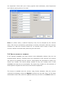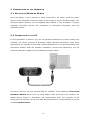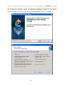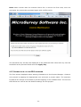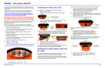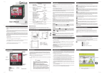
1
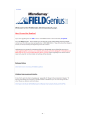
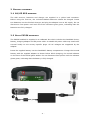
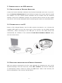
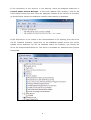
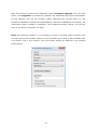
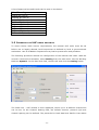
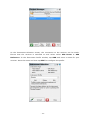
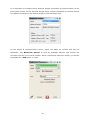
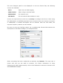
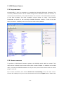
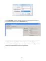
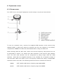
Installation Guide
Version: 1.2
English
-1-
Tablet of Contents
1
I NTRODUCTION ................................................................
................................ ..............................................
................................ .............. 3
2
B ATTERY CHARGING ................................................................
................................ .......................................
................................ ....... 6
2.1
G4/G5 GPS receiver .................................................................................... 6
2.2
Getac PS236 handheld ................................................................................ 6
3
P REPARATION OF THE GPS RECEIVER ................................................
................................ ................ 7
3.1
Installation of Prexiso Assistant................................................................... 7
3.2
Connecting to the PC ................................................................................... 7
3.3
Receiver connection with Prexiso Assistant ................................................. 7
3.4
Checking the receiver firmware version ...................................................... 9
3.5
Changing the UHF radio settings................................................................ 11
3.6
Installation of licences ............................................................................... 12
3.7
Disconnecting from the PC ......................................................................... 13
4
P REPARATION OF THE H ANDHELD ...................................................
................................ ................... 14
4.1
Setting up Windows Mobile ........................................................................ 14
4.2
Connecting to the PC ................................................................................. 14
4.3
Installation of FieldGenius ......................................................................... 15
4.4
Registration of FieldGenius ........................................................................ 17
4.5
Connection to the GPS receiver ................................................................. 18
5
GPS B OARD U PDATE ................................................................
................................ ....................................
................................ .... 22
5.1
Requirements ............................................................................................. 22
5.2
Update process .......................................................................................... 22
6
E QUIPMENT SETUP ................................................................
................................ .......................................
................................ ....... 25
6.1
Rover setup ............................................................................................... 25
6.2
Base setup ................................................................................................. 26
-2-
1 I NTRODUCTION
This guide provides complete step-by-step instructions for preparing the G4/G5 GPS
for measuring work. The instructions cover all the required installation tasks for the
Prexiso GPS receiver, Getac PS236 handheld and FieldGenius software.
Only the tasks required for the initial setup of a new G4/G5 system are described in
this document. For further information regarding the operation of the G4/G5
components, please refer to the respective User Manuals.
The User Manual for the GPS receiver is available from the G4/G5 CD and also from
the Prexiso Website at http://www.Prexiso.com (Download section). The Getac PS236
User Manual is supplied on a CD packed together with the handheld. The FieldGenius
manual
can
be
downloaded
from
the
MicroSurvey
website,
http://www.microsurvey.com/support/ in the downloads section as shown below.
-3-
at
-4-
-5-
2 B ATTERY
CHARGING
2.1 G4/G5 GPS
RECEIVER
The GPS receiver, batteries and charger are supplied in a yellow hard container.
Before using the receiver, the included PBA202 batteries should be charged. Insert
two batteries into the PCH202 charger and plug the adapter into an AC supply. Do not
disconnect from power until both the FULL indicators glow green, indicating that the
batteries are fully charged.
2.2 G ETAC PS236
HANDHELD
The PS236 handheld is supplied in a cardboard box which includes the handheld device,
battery, charging adapter and EU power cable. A suitable AC power cable may need to be
sourced locally to suit country specific plugs. All AC voltages are supported by the
adapter.
Insert the supplied battery into the handheld’s battery compartment. Charge the internal
battery with the supplied adapter as shown below. While charging, the circled indicator
on the front of the PS236 glows amber. Do not disconnect from power until the indicator
glows green, indicating that the battery is fully charged.
-6-
3 P REPARATION
OF THE
3.1 I NSTALLATION
OF
GPS
RECEIVER
P REXISO A SSISTANT
Locate the Prexiso Assistant software from Prexiso Downloads and save to your PC.
Run the Prexiso Assistant.msi file and follow the steps of the setup wizard to install
the software. An icon named Prexiso Assistant will be created onto the Windows
desktop. During the installation process, the required device drivers are also copied
onto the PC. Do not start Assistant before connecting the receiver as described below.
3.2 C ONNECTING
TO THE
PC
Insert a fully charged battery into the GPS receiver and switch it on. Connect the
supplied USB cable to the 4-pin Lemo port of the receiver (at the GPRS antenna
connection). When connecting to the USB port of the PC, the cable drivers will
automatically be installed. If the Windows Found New Hardware Wizard starts,
click the Close button.
3.3 R ECEIVER
CONNECTION WITH
P REXISO A SSISTANT
With the receiver connected to the PC, start Assistant by selecting the icon on the
Windows desktop. From the menu bar, select File…Connect. The receiver COM port
is automatically shown. Select by clicking the OK button. After a few seconds, the
device information of the receiver will be shown.
-7-
If the connection to the receiver is not working, check the assigned COM port in
Control Panel…Device Manager. In the Ports (COM & LPT) category, look for the
AT91 USB to Serial Converter. Here the COM port number of the receiver is provided,
as shown below. Select this COM port number when starting in Assistant.
If the AT91 device is not visible or the communication is not working, then the driver
can be installed manually. Right-click on the PREXISO named device and choose
Update Driver Software. Do not let Windows search for software, but choose the
driver file CompositeCDCSerial.inf. This driver is available for download from Prexiso
Downloads.
-8-
3.4 C HECKING
THE RECEIVER FIRMWARE VERSION
Before using the GPS receiver, it should be checked that the internal firmware is the
current version. Once the receiver is connected with Assistant, the installed firmware
can be seen in the Information window, at the Device Firmware Ver field. The
firmware file has the format PRXyymmddVx.xx.bin, where yymmdd is the release
date and x.xx is the version number (for example PRX120208V1.20.bin).
Visit Prexiso Downloads to check for the current version of receiver firmware. If this is
not the same version as installed, then the receiver firmware needs to be updated.
-9-
With the receiver connected to Assistant, select Firmware Upgrade from the side
menu. Click Upgrade and choose the firmware file obtained from Prexiso Downloads.
At the request, turn off the receiver. When switching the receiver back on, the
firmware installation is performed automatically. Once the installation is complete, the
information page is shown in Assistant. The installed firmware version can now be
seen at the Device Firmware Ver field.
Note: For technical reasons, it is necessary to have a microSD card inserted in the
receiver during the firmware upload. A new microSD card needs to be formatted with
a PC before use in the receiver. Use the format options as defined in the window
shown below.
- 10 -
A list of approved microSD cards can be seen in the below:
MicroSD card type
Sandisk 4G (class 4)
Samsung 4G (class 4)
Sandisk 8G (class 4)
Toshiba 4G (class 4)
Kingmax 4G (class 6)
Kingston 4G (class 4)
Kingston 2G
Kingston 4G (class 4)
Transcend 2G (class 4)
3.5 C HANGING
THE
UHF
RADIO SETTINGS
To meet country radio licence requirements, the internal UHF radio must be set
before use to legally allowed local frequencies as defined by local or governmental
authorities. Use of forbidden frequencies may lead to prosecution and penalties.
The following procedure defines the configuration of the internal UHF radio. With the
receiver connected to Assistant, select Setting from the side menu. Set the Working
Mode as Dynamic. In the Data Link field, choose UHF and click the Setting button.
The Data Link – UHF window is then displayed, where up to 8 different frequencies
can be set. In the Channel Setting field, the default channel, protocol type and
channel spacing can be defined. The protocols for both Satel and Pacific Crest radios
- 11 -
are supported. Check with your country specific local authorities, what frequencies
and channel spacing have to be used.
Note: In certain cases, a defined frequency may not be accepted by the internal
radio. This can be corrected by performing a receiver self-check. With the receiver
switched on, hold the Function button for 10 seconds until a beep is heard. The
receiver reboots 5 seconds after performing the self-check.
3.6 I NSTALLATION
OF LICENCES
If the optional GLONASS and 20Hz licences were additionally ordered, they are not
activated before delivery. Therefore when the equipment is first received, the licences
still need to be installed onto the receiver. These options are activated by means of a
licence key number. The licence always consists of only one number, even if both
GLONASS and 20Hz are to be activated. The licence key number for the activation of
these options is supplied on the invoice of the Prexiso equipment.
The licence is installed onto the receiver using Prexiso Assistant. With the receiver
connected to Assistant, select the Register function from the side menu. At the Input
Authorization Code field, enter the supplied licence key and click on the Enter button. In
- 12 -
the Status panel, a confirmation will appear once the option has been activated.
3.7 D ISCONNECTING
FROM THE
PC
Once the receiver is completely configured, it can be disconnected from the PC. From the
Assistant menu bar, select File…Disconnect. The USB cable can now be removed and
the receiver is ready for use. The receiver can be switched off by holding down the
On/Off button until you hear three beeps and LED’s turn off.
- 13 -
4 P REPARATION
4.1 S ETTING
UP
OF THE
H ANDHELD
W INDOWS M OBILE
Once the battery is fully charged or while connected to AC power, press the power
button of the handheld. Follow the steps of the wizard to setup Windows Mobile. The
Windows Mobile software on the supplied Getac PS236 is only available in English
language. Microsoft restricts the installation of alternative languages with this
operating system.
4.2 C ONNECTING
TO THE
PC
If using Windows7 or Vista on your PC, the Windows Mobile Device Centre needs to be
installed. For earlier versions of Windows, install Microsoft ActiveSync. Both these
applications are supplied on the Getac Getting Started CD or can be downloaded from
Microsoft’s website. After the software installation, connect the handheld to your PC
with the USB cable supplied with the PS236 as shown below.
The device drivers will now automatically be installed. If the Windows Found New
Hardware Wizard starts, click the Close button. After the drivers are installed, the
Mobile Device Centre or ActiveSync will automatically start. The contents of the
PS236 internal memory can be seen with Windows Explorer and are defined as a drive
named Portable Device.
- 14 -
4.3 I NSTALLATION
OF
F IELD G ENIUS
The latest version of FieldGenius can be downloaded from the MicroSurvey website, at
http://www.microsurvey.com/support/.
Click
on
the
comprehensive
list
of
installations link at MicroSurvey Downloads. Scroll down until the FieldGenius
section is found. Here the latest installation version and user manual of FieldGenius in
English is available. Click on Full Downloads and follow the described installation
procedure. Download the Devices Installer and save onto your PC.
To obtain FieldGenius in a different language, search for the webpage named
Translated Installations FieldGenius. On this page, all the available languages for
FieldGenius are shown. Click on the required language and save the installation file
onto your PC. In this case, the English version of FieldGenius does not need to be
installed.
- 15 -
With the handheld connected to your PC, run the installer file fieldgeniusxxx.exe
where xxx is the language. The PC will attempt to connect to the handheld and install
the FieldGenius software. Follow the Windows installation wizard. At the Device
Selection window, select the data collector as Windows Mobile 6.1 and higher.
- 16 -
When prompted by the handheld for where to install, choose Device. Once the
installation process is completed, the FieldGenius software can be started by selecting
it from the Windows Mobile Start Menu.
4.4 R EGISTRATION
OF
F IELD G ENIUS
When FieldGenius is started, a registration window with the Device ID is displayed as
shown below. It is possible to use FieldGenius without registration by tapping Run
Demo Mode. This provides full functionality, but is limited to the storage of 30
points.
To register your version of FieldGenius, an activation key needs to be entered. The
displayed Device ID, together with the GUID (global unique identity), is used to
obtain the key. The GUID can be found on the invoice supplied together with your
G4/G5 equipment.
The activation key can be generated by using MicroSurvey’s webportal, at the link
http://microsurveylicenseserver.com/ValidateSerialNumber.aspx.
This
webportal
is
shown in the screenshot below. At the blank serial number field, enter your GUID and
click Submit. At the next screen, enter the Device ID shown on the handheld.
- 17 -
Note: Make certain that the entered Device ID is correct the first time, since an
activation key cannot be generated again with a different ID.
The activation key will then be displayed in the password field. Enter this key into the
handheld at the provided fields and click Apply Key.
4.5 C ONNECTION
TO THE
GPS
RECEIVER
The first screen displayed when starting FieldGenius is the Project Manager. Create a
new project by tapping the appropriate icon and enter a project name. The onscreen
keyboard can always be accessed by double tapping on the editable field. The screens
that follow are used to set the default settings for this project.
- 18 -
At the Instrument Selection screen, the connection to the receiver can be made.
Ensure that the receiver is switched on and select either GPS Rover or GPS
Reference. In the Instrument Profile window, tap ADD and enter a name for your
receiver. Save the name and then tap EDIT to configure the profile.
- 19 -
It is important to configure both Antenna Height and Model & Communication of the
Instrument Profile. At the Antenna Height panel, choose the Model as Prexiso G4/G5.
The Measured Height is the default length of the telescopic pole.
At the Model & Communication panel, select the Make as Prexiso and Port as
Bluetooth. Tap Bluetooth Search to find all available devices and choose the
required receiver by its serial number. Once a connection has been made, you will be
prompted for a PIN which is 1234.
- 20 -
The Link Configure panel is now displayed. In the Link Device field, the following
choices are available:
- None:
When only raw data logging
- Other Device:
When using an external radio
- GSM Module:
For network rover
- UHF Radio:
For the internal radio as base or rover
Choose the required device and then tap Setup to configure the device. When using
the GSM Module, the NTRIP parameters can be entered. Once an internet connection
is established, a suitable mountpoint can be selected. With the UHF Radio, the
required frequency channel can be selected.
On return to the Link Configure panel, set a suitable Data Format that matches the
mountpoint or RTK base message, for example RTCM3.
When everything has been configured as required, tap Connect. The map view is
shown next and you are ready to measure. For further information on using
FieldGenius for GPS measurements, refer to the FieldGenius instruction manual in the
GPS REFERENCE chapter.
- 21 -
5 GPS B OARD U PDATE
5.1 R EQUIREMENTS
Occassionally it may be necessary to upgrade the NovAtel GPS board firmware. The
currently installed version can be viewed using Prexiso Assistant. Once the receiver is
connected with Assistant, the board firmware can be seen in the Information window,
at the GPS Firmware Ver field (example version below is 3.900). Visit Prexiso
Downloads to check for the currently available firmware version. If this is not the
same version as installed, then the receiver needs to be updated.
5.2 U PDATE
PROCESS
To perform a GPS board firmware update, the PDC220 serial cable is needed. This
cable can be ordered from Prexiso with article number 793824. In addition to the USB
cable, connect the PDC220 between the 5-pin Lemo port of the receiver and the serial
plug on your PC.
Run Prexiso Assistant and select Serial Port Forwarding from the side menu.
Choose the COM port of your serial connection and click the Open button. Switch the
- 22 -
receiver off and then on again. The serial connection is confirmed with the message
Direct link to OEM Module OK! Then exit Prexiso Assistant.
Obtain either the G4 or G5 GPS board firmware from the NovAtel website at
http://www.novatel.com/support/firmware-software-and-manuals/firmware-softwareupdates/ and extract the ZIP data onto your PC. Run the included WinLoad application
and choose COM Settings… from the menu bar.
Select your serial port number and the baudrate values as shown below.
- 23 -
Choose File Open… from the menu bar and open the HEX file that was included in
the downloaded ZIP data. Click the Write Flash button.
The update process takes approximately 5 minutes. WinLoad will display a completion
message, once the update is done. The serial cable can now be unplugged.
Switch the receiver off and on before reconnecting to Assistant. In the Information
window, the installed firmware version can be confirmed.
- 24 -
6 E QUIPMENT
6.1 R OVER
SETUP
SETUP
For a RTK rover, the G4/G5 equipment can be setup on a pole as shown below.
To use as a network rover, connect the supplied GSM antenna to the receiver plug
labelled GPRS. A SIM card needs be inserted into the slot located in the battery
compartment. Note: The PIN must be disabled before using the SIM card.
When working with the UHF radio, ensure the correct frequency and protocol are set
as described in section 3.5. Attach the radio antenna to the receiver plug labelled
UHF. The UHF radio antenna can be recognised by being longer than the GSM
antenna.
Note that the supplied antenna is only suitable for a frequency range of
430–450 MHz. When the radio is set to a frequency outside this range, an applicable
antenna needs to be used. The following antennas can be ordered from Prexiso:
639964
GAT1, Gainflex radio antenna, frequency range 400-435MHz.
667243
GAT2, Gainflex radio antenna, frequency range 435-470MHz.
- 25 -
6.2 B ASE
SETUP
The G4/G5 equipment can also be setup as a base station for the transmission of RTK
corrections as shown below.
Attach the supplied radio antenna to the receiver plug labelled UHF. To provide space
for the radio antenna, the receiver should be mounted onto the 792381 ZPC210 Base
Pole. The required RTK output message can be configured using Prexiso Assistant or
FieldGenius.
For long range RTK, a high powered radio can be used at the base station. Available
from Prexiso is the 789636 Satel EASyPro 35W radio. This radio is connected to the
receiver and an external power supply, with the 793829 PDC221 cable. The cable
needs to be connected to the 5-pin Lemo port of the receiver. When other UHF radio
types are used, a suitable cable needs to be obtained from the radio supplier.
- 26 -