1
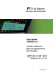
STARTING GUIDE
FRENIC-Multi LM-1
High performance compact
inverter for lift applications
3 ph 400 V 0.4 kW – 15 kW
3 ph 200 V 0.1 kW – 15 kW
SG_Multi-LM1_EN_1.4.2
Index
1.1.0
1.2.0
1.2.1
1.2.2
1.3.0
1.4.1
1.4.2
Version
- First Lift version
- Second version (RESTILING)
- 1ph 200 V series removed
- Information of S-curves corrected
- New parameters added in chapter 9
- Keypad menus information added
- EMC standard compliance updated.
- Formula for calculate no-load current is
added.
- Information about parameters P09 and P11
is added.
-Information of how to adjust experimentally
P12 is removed.
- Chapter “7.3 Torque boost gain” is added.
- Chapter “7.4 Compensation response time”
is added.
- Version updated from –LM to –LM1.
- Header changed from –LM to –LM1.
- Small text corrections.
- Over-rating table for 400 V is added.
- Factory setting is changed (updated).
- Auto tuning mode 2 is static (updated).
- Table 7.1 Sentence is added (*).
- Table 6.2 Modified (ramps deleted).
- Table 6.3 Added.
- Small text corrections.
- Speed selection according o47 is added.
Date
05.09.07
05.02.08
26.06.08
Written
J.Alonso
J.Alonso
J.Alonso
Checked
S.Ureña
S.Ureña
S.Ureña
Approved
S.Ureña
S.Ureña
S.Ureña
05.09.08
11.11.08
J.Alonso
J.Alonso
S.Ureña
S.Ureña
S.Ureña
S.Ureña
28.04.2011
S.Ureña
S.Ureña
S.Ureña
18.05.2011
S.Ureña
S.Ureña
S.Ureña
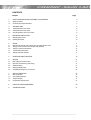
CONTENTS
Chapter
Page
1.
1.1
1.2
SAFETY INFORMATION AND CONFORMITY TO STANDARDS
Safety information
Conformity to European standards
5
5
7
2.
2.1
2.2
2.3
TECHNICAL DATA
Three-phase 400 V class series
Three-phase 200 V class series
Over-rating table for 400 V class series
8
8
8
9
3.
3.1
3.2
MECHANICAL INSTALLATION
Operating Environment
Installing the inverter
10
10
10
4.
4.1
4.2
4.3
4.4
4.5
WIRING
Removing the terminal cover and the main circuit terminal block cover
Wiring for main circuit terminals and grounding terminals
Wiring for control circuit terminals
Control terminal description
Setting up the slide switches
11
11
13
14
14
17
5.
OPERATION USING THE KEYPAD
18
6.
6.1
6.2
6.3
6.4
6.5
SETTING
Basic setting for induction motor
Quick start commissioning (auto tuning)
Additional setting
Setting the speed profile
Complete time diagram for normal travel
21
21
21
22
23
24
7.
7.1
7.2
7.3
7.4
SPECIAL OPERATIONS
Rescue operation
Auto-resetting operation
Torque boost gain
Compensation response time
25
25
26
27
27
8.
FUNCTION CODES (PARAMETERS)
28
9.
TROUBLESHOOTING
31
______________________________________________________________________
Preface
Thank you for purchasing our FRENIC-Multi LM1 series of inverters.
This product is designed to drive a three-phase induction motor for lift
applications. Read through this manual and be familiar with correct handling and
operation of this product.
Improper handling may result in incorrect operation, a short life, or even a failure
of this product as well as the motor.
Deliver this manual to the end user of this product. Keep this manual in a safe
place until this product is discarded.
Listed below are the other materials related to the use of the FRENIC-Multi LM1.
Read them in conjunction with this manual if necessary.
•
•
FRENIC-Multi User's Manual (MEH457)
FRENIC-Multi Instruction Manual (INR-SI47-1094a-E)
The materials are subject to change without notice. Be sure to obtain the latest
editions for use.
Inputs and outputs can be set to different functions using the
corresponding functions. By factory defaults these settings are already
suitable for lift applications. In this manual only the functions related to
lift applications are described.
Special functions are not described which are only used in special
applications. For questions please contact our technical staff.
______________________________________________________________________
1. SAFETY INFORMATION AND CONFORMITY TO STANDARDS
1.1 Safety information
Read this manual thoroughly before proceeding with installation, connections (wiring), operation, or maintenance and inspection. Ensure
you have sound knowledge of the device and familiarize yourself with all safety information and precautions before proceeding to operate
the inverter.
Safety precautions are classified into the following two categories in this manual.
Failure to heed the information indicated by this symbol may lead to dangerous conditions,
possibly resulting in death or serious bodily injuries.
Failure to heed the information indicated by this symbol may lead to dangerous conditions,
possibly resulting in minor or light bodily injuries and/or substantial property damage.
Failure to heed the information contained under the CAUTION title can also result in serious consequences. These safety precautions are
of utmost importance and must be observed at all times.
Application
• FRENIC-Multi LM1 is designed to drive a three-phase induction motor. Do not use it for single-phase motors or for other
purposes.
Fire or an accident could occur.
• FRENIC-Multi LM1 may not be used for a life-support system or other purposes directly related to the human safety.
• Though FRENIC-Multi LM1 is manufactured under strict quality control, install safety devices for applications where serious
accidents or material losses are foreseen in relation to the failure of it.
An accident could occur.
Installation
• Install the inverter on a non-flammable material such as metal.
Otherwise fire could occur.
• Do not place flammable object nearby.
Doing so could cause fire.
• Do not support the inverter by its terminal block cover during transportation.
Doing so could cause a drop of the inverter and injuries.
• Prevent lint, paper fibbers, sawdust, dust, metallic chips, or other foreign materials from getting into the inverter or from
accumulating on the heat sink.
Otherwise, a fire or an accident might result.
• Do not install or operate an inverter that is damaged or lacking parts.
Doing so could cause fire, an accident or injuries.
• Do not stand on a shipping box.
• Do not stack shipping boxes higher than the indicated information printed on those boxes.
Doing so could cause injuries.
Chapter 1: Safety information and conformity to standards
_______________________________________________________________________________________________________________
5
Wiring
• When wiring the inverter to the power supply, insert a recommended moulded case circuit breaker (MCCB) or residual-currentoperated protective device (RCD)/earth leakage circuit breaker (ELCB) (with overcurrent protection) in the path of power lines.
Use the devices within the recommended current range.
• Use wires of the specified size.
• When wiring the inverter to the power supply that is 500 kVA or more, be sure to connect an optional DC reactor (DCR).
Otherwise, fire could occur.
• Do not use one multicore cable in order to connect several inverters with motors.
• Do not connect a surge killer to the inverter's output (secondary) circuit.
Doing so could cause fire.
• Ground the inverter in compliance with the national or local electric code.
Otherwise, electric shock could occur.
• Qualified electricians should carry out wiring.
• Disconnect power before wiring.
Otherwise, electric shock could occur.
• Install inverter before wiring.
Otherwise, electric shock or injuries could occur.
• Ensure that the number of input phases and the rated voltage of the product match the number of phases and the voltage of
the AC power supply to which the product is to be connected.
Otherwise fire or an accident could occur.
• Do not connect the power supply wires to output terminals (U, V, and W).
• Do not insert a braking resistor between terminals P (+) and N (-), P1 and N (-), P (+) and P1, DB and N (-), or P1 and DB.
Doing so could cause fire or an accident.
• Generally, control signal wires are not reinforced insulation. If they accidentally touch any of live parts in the main circuit, their
insulation coat may break for any reasons. In such a case, ensure the signal control wire is protected from making contact with
any high voltage cables.
Doing so could cause an accident or electric shock.
• Connect the three-phase motor to terminals U, V, and W of the inverter.
Otherwise injuries could occur.
• The inverter, motor and wiring generate electric noise. Ensure preventative measures are taken to protect sensors and
sensitive devices from RFI noise.
Otherwise an accident could occur.
Operation
• Be sure to install the terminal cover before turning the power ON. Do not remove the covers while power is applied.
Otherwise electric shock could occur.
• Do not operate switches with wet hands.
Doing so could cause electric shock.
• If the auto-reset function has been selected, the inverter may automatically restart and drive the motor depending on the
cause of tripping.
(Design the machinery or equipment so that human safety is ensured after restarting.)
• If the stall prevention function (current limiter), automatic deceleration, and overload prevention control have been selected,
the inverter may operate at an acceleration/deceleration time or frequency different from the commanded ones. Design the
machine so that safety is ensured even in such cases.
Otherwise an accident could occur.
Chapter 1: Safety information and conformity to standards
6
_______________________________________________________________________________________________________________
Maintenance and inspection, and parts replacement
• Turn the power OFF and wait for at least five minutes before starting inspection. Further, check that the LED monitor is unlit
and that the DC link bus voltage between the P (+) and N (-) terminals is lower than 25 VDC.
Otherwise, electric shock could occur.
• Maintenance, inspection, and parts replacement should be made only by qualified persons.
• Take off the watch, rings and other metallic objects before starting work.
• Use insulated tools.
Otherwise, electric shock or injuries could occur.
Disposal
• Treat the inverter as an industrial waste when disposing of it.
Otherwise injuries could occur.
Others
• Never attempt to modify the inverter.
Doing so could cause electric shock or injuries.
1.2 Conformity to European standards
The CE marking on Fuji Electric products indicates that they comply with the essential
requirements of the Electromagnetic Compatibility (EMC) Directive 89/336/EEC issued by the
Council of the European Communities and the Low Voltage Directive 73/23/EEC.
Inverters with built-in EMC filter that bear a CE marking are in conformity with EMC directives.
Inverters having no built-in EMC filter can be in conformity with EMC directives if an optional
EMC compliant filter is connected to them.
General purpose inverters are subject to the regulations set forth by the Low Voltage Directive in
the EU. Fuji Electric declares the inverters bearing a CE marking are compliant with the Low
Voltage Directive.
FRENIC-Multi LM1 inverters are in accordance with the regulations of following council directives
and their amendments:
EMC Directive 89/336/EEC (Electromagnetic Compatibility)
Low Voltage Directive 73/23/EEC (LVD)
For assessment of conformity the following relevant standards have been taken into
consideration:
EN61800-3:2004
EN50178:1997
The FRENIC-Multi LM1 inverters are categorized as category C2 according to the
EN61800-3:2004. When you use these products in the domestic environment, you may
need to take appropriate countermeasures to reduce or eliminate any noise emitted from
these products.
Chapter 1: Safety information and conformity to standards
_______________________________________________________________________________________________________________
7
2. TECHNICAL DATA
2.1 Three-phase 400 V class series
Items
Specifications
Input ratings
Output ratings
Type (FRN□□□E1E/S-4LM1)
0.4
0.75
1.5
2.2
4.0
5.5
7.5
11
15
Nominal applied motor [kW]
0.4
0.75
1.5
2.2
4.0
5.5
7.5
11
15
Rated capacity [kVA]
1.1
1.9
2.8
4.1
6.8
9.9
13
18
22
Rated voltage [V]
Rated current [A] (*1)
Overload capability
Rated frequency
Main power supply
Voltage/frequency variations
Rated current [A]
1.5
Three-phase 380 to 480 V (With AVR)
2.5
3.7
5.5
9.0
13
18
24
150 % of rated current for 1min or 200 % of rated current for 0.5 s
50/60 Hz
Three-phase 380 to 480 V,50/60 Hz
Voltage: +10 to -15 % (Voltage unbalance: 2 % or less), Frequency: +5 to -5 %
30
With DCR
0.85
1.6
3.0
4.4
7.3
10.6
14.4
21.1
28.8
Without DCR
1.7
3.1
5.9
8.2
13.0
17.3
23.2
33.0
43.8
Braking
Required power supply capacity
0.6
1.1
2.0
2.9
4.9
7.4
10
15
20
[kVA]
Braking torque [%]
100
70
40
20
DC braking
Starting frequency: 0.1 to 60.0 Hz, Braking time: 0.0 to 30.0 s, Braking level: 0 to 100 %
Transistor for braking resistor
Built-in
Applicable safety standards
UL508C, C22.2No.14, EN50178: 1997
Enclosure
IP20 (IEC60529) / UL open type (UL50)
Cooling method
Natural cooling
Fan cooling
Mass [kg]
1.1
1.2
1.7
1.7
2.3
3.4
3.6
6.1
7.1
EMC filter built-in (E1E) (*2)
EMC standard Emission
Category C2 (EN 61800-3: 2004)
Category C3 (EN 61800-3: 2004)
compliance
Immunity
2nd Env. (EN 61800-3: 2004)
Mass [kg]
1.5
1.6
2.5
2.5
3.0
4.8
5.0
8.1
9.1
(*1) Rated current for Ta= 50 ºC, Cf= 8 kHz, ED=40 %
(*2) Available only in 4.0 kW (400 V)
2.2 Three-phase 200 V class series
Items
Specifications
Braking
Input ratings
Output ratings
Type (FRN□□□E1S-2LM1)
Nominal applied motor [kW]
Rated capacity [kVA]
Rated voltage [V]
Rated current [A] (*1)
(*2)
0.1
0.1
0.30
0.2
0.2
0.57
0.4
0.4
1.1
0.8
(0.7)
1.5
(1.4)
3.0
(2.5)
Overload capability
Rated frequency
Main power supply
Voltage/frequency variations
Rated current [A]
0.75
1.5
2.2
3.7
5.5
0.75
1.5
2.2
3.7
5.5
1.9
3.0
4.1
6.4
9.5
Three-phase 200 to 240 V (With AVR)
7.5
7.5
12
11
11
17
15
15
22
5.0
(4.2)
33
(31)
47
(44)
60
(57)
8.0
(7.0)
11
(10)
17
(16.5)
25
(23.5)
150 % of rated current for 1min or 200 % of rated current for 0.5 s
50/60 Hz
Three-phase 200 to 240 V,50/60 Hz
Voltage: +10 to -15 % (Voltage unbalance: 2 % or less), Frequency: +5 to -5 %
With DCR
0.57
0.93
1.6
3.0
5.7
8.3
14.0
21.1
28.8
42.2
57.6
Without DCR
1.1
1.8
3.1
5.3
9.5
13.2
22.2
31.5
42.7
60.7
80.0
0.2
0.3
0.6
1.1
2.0
2.9
4.9
7.4
10
15
20
Required power supply capacity
[kVA]
Braking torque [%]
150
100
70
40
DC braking
Starting frequency: 0.1 to 60.0 Hz, Braking time: 0.0 to 30.0 s, Braking level: 0 to 100 %
Transistor for braking resistor
Built-in
Applicable safety standards
UL508C, C22.2No.14, EN50178: 1997
Enclosure
IP20 (IEC60529) / UL open type (UL50)
Cooling method
Natural cooling
Fan cooling
Mass [kg]
0.6
0.6
0.7
0.8
1.7
1.7
2.3
3.4
Mass [kg]
0.7
0.7
0.8
0.9
2.4
2.4
2.9
5.1
(*1) Rated current for Ta= 40 ºC, Cf= 8 kHz, ED=40 %
(*2) Rated current (in brackets) for Ta= 50 ºC, Cf= 8 kHz, ED=40 %
8
20
3.6
5.3
6.1
10.3
Chapter 2: Technical data
_______________________________________________________________________________________________________________
7.1
11.3
2.3 Over-rating table for 400 V series
Inverter
Size
Maximum
motor POWER
I rated
(A)
Overload
(%)
Time
(s)
Overload
(%)
Time
(s)
4.0
5.5
7.5
11
15
4 kW
5.5 kW
7.5 kW
11 kW
15 kW
10.4
15
20.8
27.6
34.5
130
130
130
130
130
60
60
60
60
60
173
173
173
174
174
0.5
0.5
0.5
0.5
0.5
Rated current for Ta= 45 ºC, Cf= 8 kHz, ED=40 %
Chapter 2: Technical data
_______________________________________________________________________________________________________________
9
3. MECHANICAL INSTALLATION
3.1 Operating Environment
Install the inverter in an environment that satisfies the requirements listed in Table 3.1.
Table 3.1 Environmental Requirements
Item
Specifications
Site location
Indoors
Ambient
temperature
-10 to +50°C (Note 1)
Relative
humidity
5 to 95% (No condensation)
Atmosphere
The inverter must not be exposed to dust,
direct sunlight, corrosive gases, flammable
gas, oil mist, vapor or water drops. (Note 2)
The atmosphere must contain only a low
level of salt.
(0.01 mg/cm2 or less per year)
The inverter must not be subjected to
sudden changes in temperature that will
cause condensation to form.
Altitude
1000 m max. (Note 3)
Atmospheric
pressure
86 to 106 kPa
Vibration
3 mm (Max. amplitude)
9.8 m/s2
2 m/s2
1 m/s2
2 to less than 9 Hz
9 to less than 20 Hz
20 to less than 55 Hz
55 to less than 200 Hz
Table 3.2 Output Current Derating
Factor in Relation to Altitude
Altitude
Output current
derating factor
1000 m or lower
1.00
1000 to 1500 m
0.97
1500 to 2000 m
0.95
2000 to 2500 m
0.91
2500 to 3000 m
0.88
(Note 1) When inverters are mounted sideby-side without any gap between them (less
than 5.5 kW), the ambient temperature
should be within the range from -10 to
+40°C.
(Note 2) Do not install the inverter in an
environment where it may be exposed to
cotton waste or moist dust or dirt which will
clog the heat sink in the inverter. If the
inverter is to be used in such an
environment, install it in the panel of your
system or other dustproof containers.
(Note 3) If you use the inverter in an altitude
above 1000 m, you should apply an output
current derating factor as listed in Table 3.2.
3.2 Installing the Inverter
(1) Mounting base
The temperature of the heat sink will rise up to approx. 90°C during
operation of the inverter, so the inverter should be mounted on a base made
of material that can withstand temperatures of this level.
Install the inverter on a base constructed from metal or other non-flammable
material.
A fire may result with other material.
(2) Clearances
Ensure that the minimum clearances indicated in Figure 3.1 are maintained
at all times. When installing the inverter in the panel of your system, take
extra care with ventilation inside the panel as the temperature around the
inverter will tend to increase. Do not install the inverter in a small panel with
poor ventilation.
Figure 3.1 Mounting Direction and
Required Clearances
Prevent lint, paper fibers, sawdust, dust, metallic chips, or other foreign materials from getting into the inverter or from
accumulating on the heat sink.
This may result in a fire or accident.
Chapter 3: Mechanical Installation
10
_______________________________________________________________________________________________________________
4. WIRING
Follow the below procedure (In the following description, the inverter has already been installed).
4.1 Removing the terminal cover and the main circuit terminal block cover
(1) For inverters with a capacity of less than 5.5 kW
To remove the terminal cover, put your finger in the dimple of the terminal cover (labelled
"PULL"), and then pull it up toward you.
To remove the main circuit terminal block cover, hold its right and left ends with your fingers
and slide it toward you (Refer to figure 4.1)
Figure 3.1 Removing the Covers (For Inverters with a Capacity of Less than 5.5 kW)
(2) For inverters with a capacity of 5.5 and 7.5 kW
To remove the terminal cover, first loosen the terminal cover fixing screw, put your finger in
the dimple of the terminal cover (labelled "PULL"), and then pull it up towards you.
To remove the main circuit terminal block cover, put your thumbs on the handles of the main
circuit terminal block cover, and push it up while supporting it with your fingers (Refer to
Figure 4.2).
Figure 4.2 Removing the Covers (For Inverters with a Capacity of 5.5 and 7.5 kW)
Chapter 4: Wiring
_______________________________________________________________________________________________________________
11
When mounting the main circuit terminal block cover, fit it according to the guide on the inverter.
Figure 4.3 Mounting the main circuit terminal block cover
(For Inverters with a Capacity of 5.5 and 7.5 kW)
(3) For inverters with a capacity of 11 and 15 kW
To remove the terminal cover, first loosen the terminal cover fixing screw, put your finger in
the dimple of the terminal cover (labelled "PULL"), and then pull it up towards you.
To remove the main circuit terminal block cover, hold the handles on the both sides of the
main circuit terminal block cover, and pull it up (Refer to figure 4.4)
Figure 4.4 Removing the Covers (For Inverters with a Capacity of 11 and 15 kW)
When mounting the main circuit terminal block cover, fit it according to the guide on the inverter.
Insert the main circuit terminal block cover by fitting the part labelled "GUIDE" according to the guide on the inverter.
Push where "PUSH" are labelled to snap it into the inverter.
Figure 4.5 Mounting the Main Circuit Terminal Block Cover
(For inverters with a capacity of 11 and 15 kW)
12
Chapter 4: Wiring
_______________________________________________________________________________________________________________
4.2 Wiring for main circuit terminals and grounding terminals
The diagram below shows main circuit and grounding terminals connexion
2
DC reactor
THR
PLC
1
L1
L2
L3
When installing DC reactor remove
the bridge between P1 and P+
Input line fuses
P1
P+
DB
N-
EMC Filter
2 Motor contactors
L1
L1'
L1 / R
U
L2
L2'
L2 / S
V
L3
L3'
L3 / T
W
GND
GND
GND
GND
Motor
FRENIC-Multi LM1
Figure 4.6 Main circuit terminal connexions
Symbol
L1/R, L2/S, L3/T
U, V, W
P1, P(+)
P(+), DB
G
Name
Main circuit power
inputs
Inverter outputs
DC reactor
connection
DC braking resistor
Grounding for
inverter and motor
Functions
Connect the three-phase input power lines
Connect a three-phase motor.
Connect an optional DC reactor (DCRE) for improving power factor. In that case, remove the bridge
already installed.
Connect an optional braking resistor.
Grounding terminals for the inverter’s chassis (or case) and motor. Earth one of the terminals and
connect the grounding terminal of the motor. Inverters provide a pair of grounding terminals that
function equivalently.
Table 4.1 Symbols, names and functions of the main circuit power terminals
Please connect the screen in both motor and inverter sides. Ensure that the screen is
continued also through the contactors.
It is recommended to use a braking resistor with clixon and connect the fault signal to
the controller and also to the inverter, configuring a digital input with External alarm
function (THR). To do so, set the related function (E01 to E05) to 9.
It is recommended the use of a thermal relay in the braking resistor circuit. This relay
should be set up that it only trips in the case that there is a short circuit in the braking
transistor.
Chapter 4: Wiring
_______________________________________________________________________________________________________________
13
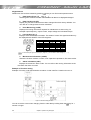
4.3 Wiring for control circuit terminals
The diagram below shows a basic connection example for running the inverter with terminal
commands.
12
11
Analog Inputs
V2
C1
11
Slide switches on the
control board for
hardware configuration
Keypad connector or
RS 485 (Modbus RTU)
FRENIC-Multi LM1
Voltage power supply +24 VDC
30A
PLC
30B
Lift direction:
Up
FWD
Down
REV
Relay output
for any alarm
30C
CM
Y1
X1
X1 to X3: Binary
combination inputs for
speed set points selection
(see Table 6.2)
Brake control signal
Y2
Motor contactors control signal
CMY
Common for transistor outputs
X2
X3
Coast to stop
(Inverter enable)
X4
X5
Common 0V
CM
GND
Figure 4.7 Control terminal connexions
4.4 Control terminals description
a. Analog inputs
Using analog inputs the motor speed can be set without steps (stageless).
b. Digital Inputs
The digital inputs can operate using NPN or PNP logic. The selection of the logic is set using
slide switch SW1 located on the control PCB. Factory setting is PNP (Source) Logic.
Connection example using PNP Logic:
FRENIC-Multi LM1
Lift controller
Up
Speed 1
PLC (+24 V)
FWD
X1
Figure 4.8: Normal connection using free potential contacts of the lift controller.
14
Chapter 4: Wiring
_______________________________________________________________________________________________________________
FRENIC-Multi LM1
PLC (+24 V)
Lift controller
Up
Speed 1
+24 V
FWD
+24 V
X1
+24 V
CM
+
External power supply
Figure 4.9: Connection using external power supply
Terminal
FWD
REV
CM
X1 to X2
X3
X4
X5
Function description of the digital inputs
Left rotation direction of the motor seen from the shaft side.
Depending on the mechanical set up this can be UP or DOWN direction of the cabin
Right rotation direction of the motor seen from the shaft side.
Depending on the mechanical set up this can be DOWN or UP direction of the cabin.
Common 0V
Digital inputs for speed selection. From binary combination 7 different speeds can be selected.
Configured from factory as “BATRY” for UPS operation.
Inverter output stage enable. Cancellation of the signal during travel stops immediately the motor (brake
signal is turned OFF).
Configured from factory as a reset alarm
Table 4.2: Description of transistor inputs (optocoupled inputs)
Electrical specification of digital inputs using PNP (Source) Logic
Voltage
ON
OFF
ON
Current
22 to 27 V
0 to 2 V
Min. 2.5 mA
Max. 5.0 mA
c. Relay output
Terminals 30A, 30B and 30C are configured from factory with the functions described in the
table below. Other functions can be set using functions E27.
Terminals
30A, 30B and
30C
Function description of the relay outputs
Inverter alarm.
Switching contact. In case of fault, the motor stops and the contact 30C-30A switches.
Contact rating: 250 VAC; 0.3 A / 48 VDC;0.5 A
d. Transistor outputs
Terminals Y1 to Y2 are configured from factory with the functions described in the table
below. Other functions can be set using functions E20 to E21.
Figure 4.10: Connection using PNP (Source) Logic
Chapter 4: Wiring
_______________________________________________________________________________________________________________
15
Terminal
Y1
Y2
CMY
Function description of the transistor outputs
Motor brake control. Normally the lift controller will also determine the status of the motor brake (depending
on the safety chain status).
Motor contactors control. Normally the lift controller will also determine the status of the motor contactors
(depending on the safety chain status).
Common for transistor outputs
Table 4.3: Description of transistor outputs (optocoupled outputs)
Electrical specification of transistor outputs
Voltage
ON
OFF
ON
OFF
Operation current
Leakage current
2 to 3 V
24 to 27 V
Max. 50 mA
0.1 mA
Maximum connectable voltage is 27 VDC – inductive loads should not be connected directly
(they should be connected through a relay or optocoupler)
e. Communication connections (keypad and PC)
FRENIC-Multi LM1 has one RS485 port available for communication
The RS485 port (through a RJ-45 connector) makes possible the connection of the FRENICMulti LM standard and multifunctional keypad or a PC. Only one communication is possible at
the same time.
i.
Keypad
The keypad can be remotely connected up to 20m
Pin Nr.
1 and 8
2 and 7
3 and 6
4
5
Signal
VDC
GND
None
DXDX+
Function
Keypad power supply
Common for VDC
Free
RS485 data (- )
RS485 data (+)
Comments
5V
Ground (0 V)
Not used
When the keypad is connected, SW3 switch on the
control board must be set to OFF position (Factory set).
Table 4.4: RJ-45 connector pin assignment.
Figure 4.11: RJ-45 connector (inverter)
ii. Connection with PC
FRENIC LOADER2 is a PC program available, giving a comfortable tool for the inverter
set up and diagnosis. The connection is done through the RS 485 port (on the RJ-45
connector).
For the connection through the USB port of a PC, a USB-RS485 converter is needed,
like for example EX9530 (Expert).
Figure 4.12: Connection of FRENIC Loader2 with PC
16
Chapter 4: Wiring
_______________________________________________________________________________________________________________
4.5 Setting up the slide switches
Before changing the switches, turn OFF the power and wait more than five minutes. Make sure that the LED monitor is turned OFF.
Also, make sure, using a multimeter or a similar instrument, that the DC link bus voltage between the terminals P (+) and N (-) has
dropped below the safe voltage (+25 VDC).
An electric shock may result if this warning is not heeded as there may be some residual electric charge in the DC bus
capacitor even after the power has been turned off.
Switching the slide switches located on the control PCB and interface PCB allows you to
customize the operation mode of the analogue output terminals, digital I/O terminals, and
communications ports. The locations of those switches are shown in Figure 4.13.
To access the slide switches, remove the terminal cover and keypad. Table 4.5 lists function of
each slide switch.
For details on how to remove the terminal cover, refer to Section 4.1, "Removing the
terminal cover and main circuit terminal block cover."
Slide Switch
SW1
Function
Switches the service mode of the digital input terminals between SINK and SOURCE.
▪ To make the digital input terminal [X1] to [X5], [FWD] or [REV] serve as a current sink, turn SW1 to the SINK
position. To make them serve as a current source, turn SW1 to the SOURCE position. Factory default: SOURCE
SW3
Switches the terminating resistor of RS-485 communications port on the inverter on and off.
▪ To connect a keypad to the inverter, turn SW3 to OFF. (Factory default)
▪ If the inverter is connected to the RS-485 communications network as a terminating device, turn SW3 to ON.
SW6
Normally not used for lift applications
SW7
Switching SW7 to C1 and SW8 to ON we are able to protect the motor by means of thermistor. The thermistor has to
be connected between terminals C1 and 11.
SW8
See functions H26 and H27.
Table 4.5 Function of Each Slide Switch
The following figure shows the location of slide switches for the input/output terminal
configuration.
Switching example
SW3
OFF
ON
Factory
default
SW6
FMA
SW7
C1
SW8
OFF
SW1
SOURCE
Factory
default
FMP
V2
ON
SINK
-
Figure 4.13 Location of the Slide Switches
Chapter 4: Wiring
_______________________________________________________________________________________________________________
17
5. OPERATION USING THE KEYPAD
7-segment LED
monitor
As shown on the right, the keypad consists of a fourdigit LED monitor, six keys, and five LED indicators.
The keypad allows you to run and stop the motor,
monitor running status, and switch to the menu
mode. In the menu mode, you can set the function
code data, monitor I/O signal states, maintenance
information, and alarm information.
Program/
Reset key
RUN key
RUN LED
Function/
Data key
STOP
key
UP key
Item
LED
indicators
LED Monitor,
Keys, and LED
Indicators
DOWN key
Functions
Four-digit, 7-segment LED monitor which displays the following according to the operation modes.
LED
Monitor
In Running mode:
Running status information (e.g., output frequency, current, and voltage)
In Programming mode: Menus, function codes and their data
In Alarm mode:
Alarm code, which identifies the alarm factor if the protective function is activated.
Program/Reset key which switches the operation modes of the inverter.
In Running mode:
In Programming mode:
In Alarm mode:
Pressing this key switches the inverter to Programming mode.
Pressing this key switches the inverter to Running mode.
Pressing this key after removing the alarm factor will switch the inverter to Running mode.
Function/Data key which switches the operation you want to do in each mode as follows:
In Running mode:
Pressing this key switches the information to be displayed concerning the status of the
inverter (output frequency (Hz), output current (A), output voltage (V), etc.).
In Programming mode: Pressing this key displays the function code and sets the data entered with
and
keys.
In Alarm mode:
Pressing this key displays the details of the problem indicated by the alarm code that has
come up on the LED monitor.
Operation
Keys
RUN key. Press this key to run the motor.
STOP key. Press this key to stop the motor.
Item
and
UP and DOWN keys. Press these keys to select the setting options and change the function code data displayed on
the LED monitor.
LED Monitor,
Keys, and LED
Indicators
Functions
RUN LED
Illuminates when any run command to the inverter is active.
KEYPAD
CONTROL LED
Illuminates when the inverter is ready to run with a run command entered by the
Programming and Alarm modes, you cannot run the inverter even if the indicator lights.
LED
Indicators Unit and mode
expression by
the three LED
indicators
key (F02 = 0, 2, or 3). In
The three LED indicators identify the unit of numeral displayed on the LED monitor in Running mode by combination
of lit and unlit states of them.
Unit: kW, A, Hz, r/min and m/min
While the inverter is in Programming mode, the LEDs of
Hz and kW illuminate.
Hz
A
kW
Simultaneous keying
Simultaneous keying means: pressing two keys at the same time. The FRENIC-Multi LM1
supports simultaneous keying as listed below. The simultaneous keying operation is expressed
by a "+" letter between the keys throughout this manual.
(For example, the expression " + keys" stands for pressing the key while holding down
the key.)
Operation mode
Programming mode
Alarm mode
Simultaneous keying
+
keys
+
keys
+
keys
Used to:
Change certain function code data (Refer to codes F00, H03, and H97 in
Chapter 8 "Function codes").
Switch to Programming mode without resetting alarms currently occurred.
Chapter 5: Operation using the Keypad
_______________________________________________________________________________________________________________
18
FRENIC-Multi LM1 features the following three operation modes:
■ Running mode: This mode allows you to enter run/stop commands in regular operation. You
can also monitor the running status in real time.
■ Programming mode: This mode allows you to configure function code data and check a variety
of information relating to the inverter status and maintenance.
■ Alarm mode: If an alarm condition arises, the inverter automatically enters Alarm mode. In this
mode, you can view the corresponding alarm code* and its related information
on the LED monitor.
* Alarm code: Indicates the cause of the alarm condition that has triggered a protective function.
For details, refer to Chapter 9, "Troubleshooting".
(*1)
(*2)
(*3)
(*4)
The speed monitor allows you to select the desired one from the seven speed monitor items by using function code E48.
Not used in lift applications.
Not used in lift applications.
Applicable only when the full-menu mode is selected (E52 = 2).
Figure 5.1 Transitions between Basic Screens in Individual Operation Mode
Chapter 5: Operation using the Keypad
_______________________________________________________________________________________________________________
19
Keypad menus
Partial menu list can be accessed by pressing
. Here
you can find most important menus.
1.
Data Setting (From 1.F_ _ to 1.o_ _ )
Selecting each of these function codes enables its data to be displayed/changed.
Data Checking (2.rEP)
Display only function codes that have been changed from their factory defaults. You
can refer to or change those function code data.
2.
3.
Drive Monitoring (3.oPE)
Displays the running information required for maintenance or test running, for
example output frequency, output current, output voltage and calculated torque.
4.
I/O Checking (4.I_o)
Displays external interface information. The status of control I/O signal terminals may
be displayed with ON/OFF of the LED segment.
Segments
a
b
c
d
e
f
g
h
LED 4
30A/B/C
---------------
LED 3
Y1-CMY
Y2-CMY
-------------
LED 2
----------XF
XR
RST
LED 1
FWD
REV
X1
X2
X3
X4
X5
---
If all terminal input signals are OFF (open), segment "g" on all of LED1 to LED4 will light ("– – – –").
5.
Maintenance Information (5.CHE)
Shows the inverter condition: runtime, main capacitors capacitance, firmware version.
6.
Alarm information (6.AL)
Displays the recent four alarm codes. You can refer to the running information at the
time when the alarm occurred.
Example of Function setting
Example of function code data changing procedure, in that case F01 is setting from 0 to 2.
Figure 5.2 Function setting procedure
You can move the cursor when changing function code data by holding down the
second or longer.
key for 1
Chapter 5: Operation using the Keypad
_______________________________________________________________________________________________________________
20
6. SETTING
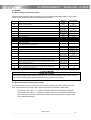
6.1 Basic setting for induction motors
Set the following function codes according to motor ratings and application values. For the motor,
check the rated values printed on the nameplate of the motor.
Function
Meaning
F03
Maximum rotating speed (Hz)
F04
Motor rated speed from name plate (Hz)
F05
Motor rated voltage from name plate (V)
F09
Torque boost for torque vector control (%)
F11
Overload detection level
F20
F21
F22
F23
F24
F25
E03
E04
DC – Braking (Start frequency)
DC – Braking (Level)
DC – Braking (Time)
Starting frequency
Starting frequency (Hold time)
Stop frequency
Control type selection
1: Dynamic torque vector control
2: V/f control with slip compensation active
Terminal [X3] Function
Terminal [X4] Function
E46
Language setting (clear text function description)
P01
Motor number of poles from manufacturer data sheet or motor name plate
F42
P02
P03
P06
P07
P08
P12
o40
Motor rated capacity (power) from name plate (kW)
Motor rated current from name plate (A)
Motor no-load current (A)
The Auto tuning procedure measures the value of this function (when P04=2)
Motor stator resistance (R1) in %.
The Auto tuning procedure measures the value of this function (when P04=1 or 2)
Motor stator reactance (X1) in %.
The Auto tuning procedure measures the value of this function (when P04=1 or 2)
Slip frequency (Hz).
The Auto tuning procedure measures the value of this function (when P04=2)
Torque Boost gain for normal operation
Table 6.1 Basic settings for induction motors
Factory
setting
50 Hz
50 Hz
Depends on the
input voltage
Depends on the
inverter capacity
Depends on the
range
0.50 Hz
80 %
1.50 s
0.5 Hz
0.80 s
0.2 Hz
Basic Setting
Depends on the
motor
Depends on the
motor
Depends on the
motor
Only used in V/f
control (F42=0 or 2)
Same as P03
0.5 Hz
80 %
1.5 s
0.5 Hz
0.50 s
0.2 Hz
1
1
2
1007
2
1007
Depends on the
country
Depends on the
motor
Depends on the
motor
Depends on the
motor
1
4
Depends on the
inverter capacity
Depends on the
inverter capacity
Depends on the
inverter capacity
Depends on the
inverter capacity
Depends on the
inverter capacity
Depends on the
inverter capacity
1.06
See chapter 6.3
Automatic
Automatic
See chapter 6.3
1.06
Main power supply of the inverter is required when you want to change function codes. In other
cases the inverter protects itself and change function codes is not possible.
6.2 Quick start commissioning (auto tuning)
It is recommended to perform the auto tuning procedure before running the motor for the first
time. There are two auto tuning modes: auto tuning mode 1 and mode 2 (both static).
Auto tuning mode 1 (P04 = 1): Values of function codes P07 and P08 are measured.
Auto tuning mode 2 (P04 = 2): Values of function codes P07 and P08 are measured as
well as the value of function code P06 (no load current) and the value of function code
P12 (rated slip frequency).
Chapter 6: Setting
_______________________________________________________________________________________________________________
21
Auto tuning procedure
1.
2.
3.
4.
5.
6.
7.
8.
9.
Is the motor correctly connected?
Turn on inverter mains supply.
Switch the operation mode from remote to local (setting F02 = 2 or 3).
Please, set the functions described in the previous table (6.1).
If there are any kind of contactors between the motor and the inverter, please
close them manually. If the contactors are controlled by the inverter it will by
closed automatically.
Active inverters enable (Terminal X4).
Set P04 to 1 (Auto tuning mode 1), press FUNC/DATA and press RUN (the
current flowing through the motor windings will generate a sound). The auto
tuning takes a few seconds until it finishes by itself.
P07 and P08 will be measured (also P06 and P12 if Auto tuning mode 2 has
been selected) and stored automatically in the inverter.
The auto tuning procedure has been finished.
6.3 Additional setting
No-load current (function P06)
The no-load current (function P06) defines the value of the current of the motor when no load is
applied to the motor (exciting current).
Typical values of the no-load current range are from 30 % of P03 up to 70 % of P03. In the
majority of the cases the value measured by the auto tuning procedure will be correct (when
P04=2). In some cases the auto tuning procedure can not be finished correctly (due to special
behaviour of the motor). In this later case the value of P03 must be set manually. For calculate
no-load current you can use the formula P06 =
(P03 )2 − P02 * 1000
2
1.47 * F05
Too low values in P03 will make that the motor does not have enough torque. Too high values
will make that the motor oscillates (this oscillation will cause a vibration in the motor that is
transmitted to the cabin).
Slip frequency (function P12)
The slip frequency function defines the value of the slip frequency of the motor. Is the key
function for a good slip compensation by the inverter; this means that this function is very
important in open loop control of induction motors for a good landing accuracy because it will
ensure that the rotating frequency of the motor is the same regardless of the load condition of the
motor.
In the majority of the cases the value measured by the auto-tuning procedure will be correct. In
some cases the auto-tuning procedure can not be finished correctly (due to special behaviour of
the motor). In this later case the value of P12 must be set manually.
To set function P12 manually we can calculate it from the following formula:
P12 =
(Synchrono us speed(rpm) − Rated speed(rpm)) × Nom Frequency
x0.7
Synchronou s speed(rpm)
Slip compensation gains (functions P09 for driving mode and P11 for braking mode)
The slip frequency can be also compensated in both driving and braking mode. The experimental
method for adjust these values is following. You need to test one floor level with cabin empty
going up and down:
- If the cabin speed going up is smaller than the desired speed (the cabin don’t reach
the floor level) decrease 10 % the value of P11 (braking mode).
- If the cabin speed going down is higher than the desired speed (the cabin pass the
floor level) decrease 10 % the value of P09 (driving mode).
Chapter 6: Setting
_______________________________________________________________________________________________________________
22
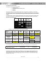
6.4 Setting the speed profile
The setting of the speed profile includes:
Travelling speed
Acceleration and deceleration times
S-curves
Soft start
For the high speed, each intermediate speed and creep speed the acceleration, deceleration
times and S-curves can be set according the table 6.3 (below). The setting of the S-curve means
the speed change in terms of percentage of the maximum speed (F03) used for the acceleration
change.
The setting ranges of the acceleration/deceleration times and reference speeds are determined
according to the switching of digital input functions SS4, SS2 and SS1 (please, see functions
E01-E05) as described below.
FWD/REV
X3
X2
X1
OFF
ON
ON
ON
ON
ON
ON
ON
ON
(SS4)
OFF
OFF
OFF
OFF
OFF
ON
ON
ON
ON
(SS2)
OFF
OFF
OFF
ON
ON
OFF
OFF
ON
ON
(SS1)
OFF
OFF
ON
OFF
ON
OFF
ON
OFF
ON
ٛ Reference
speed
selected
0.00 Hz
F01*
C05
C06
C07
C08
C09
C10
C11
Table 6.2 Speed selection table
* Setting F01=0 an extra speed on the keypad is available
After Change
Before
Change
Stop
Zero
Speed
Stop
-
Dec:
o65 / o66 / E10
Zero Speed
Dec:
o65 / o66 / E10
-
High Speed
Maintenance
Speed
Dec:
o65 / o66 / E10
Dec:
o65 / o66 / E10
Creep Speed
Dec:
o65 / o66 / E10
Dec:
o65 / o66 / E10
UPS operation
Speed
Dec:
- / - / E11
-
High Speed
Maintenance
Speed
Creep
Speed
UPS operation
Speed
Acc:
o65 / o65 / E10
Acc:
o65 / o65 / E10
Acc:
- / - / E11
Dec:
o63 / o64 / F08
-
Acc:
o61 / o62 / F07
Acc:
o65 / o65 / E10
Dec:
o65 / o65 / E10
-
-
-
-
Acc:
o61 / o62 / F07
Acc:
o61 / o62 / F07
Acc:
o61 / o62 / F07
Dec:
o63 / o64 / F08
-
Table 6.3 S-curves and linear ramp selection table
S-curve setting of Start period / S-curve setting of End period / Acceleration time or Deceleration time
High Speed
Maintenance Speed
>
o47=10.00 Hz
>=
Creep Speed
The setting of soft-start is the time of accelerating from zero speed to starting speed (function
H65). This function may be used to obtain a soft start in lift installations with high friction. The
factory setting is 0.25 s and the setting range is from 0.00 to 60.00 s. We recommend among
0.25 and 0.50 s to start.
Chapter 6: Setting
_______________________________________________________________________________________________________________
23
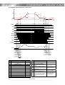
6.5 Complete time diagram for normal travel
Speed
o62
o63
C05
F08
o64
F07
o61
o65
C07
F23/J69
o66
F20/F25/J71
Time
E10
a
b
c
d
BX/BBX
ON
FWD
ON
SS1
ON
SS2
e
ON
ON
SW52-2
ON
Magnet
contactor
ON
OUTPUT
ON
BRKS
ON
Mechanical
Brake
Release
J68 (%)
t1
t2
t8
t9
t10
t11
t12
t3
t4
t5
t6
t7
Sign
Contents
Function
t1
Magnet contactor operation delay time
-
t2
Magnet contactor operation delay waiting
time
o75
t3
Soft Start ramp time
H65
t4
J68 reach delay time
-
t5
Brake control ON delay time
J70
t6
Mechanical brake release delay time
-
t7
Starting speed operation time
F24
t8
DC braking injection time
F22
t9
Brake control OFF delay time
J72
t10
Mechanical brake close delay time
-
t11
Magnet contactor control OFF delay time
o76
t12
Magnet contactor operation delay time
-
Explanation of inverter status
a
b
c
d
e
The inverter waits to begin the output
from operation command ON to
turning on magnet contactor
The inverter is driven by starting
speed until mechanical brake is
released.
The inverter accelerates to high
speed.
Afterwards, the inverter is driven at a
constant speed.
The inverter decelerates to the creep
speed.
The inverter decelerates to the
stopping speed.
The inverter keeps driving at stopping
speed from less than DC brake
starting frequency to the time of F22
passes.
Inverter status
Inverter stopped
Inverter operate
starting speed
Inverter in operation
Inverter in operation
The inverter shifts from
the operating state to
the stopped state.
Chapter 6: Setting
_______________________________________________________________________________________________________________
24
7. SPECIAL FUNCTIONS
7.1 Rescue operation
The rescue operation enables the inverter (during undervoltage situation) to move the elevator
cage to the nearest floor. The rescue is done by means of a UPS power supply.
Requirements for rescue operation:
•
The BATRY function (63) must be assigned to any digital input terminal. From factory
setting this function is set in terminal X3.
•
An AC voltage must be supplied from the UPS to the main circuit (R-T). The voltage
level will differ depending on the operation speed, load, motor and type of instalation.
•
The BATRY function must be turned on.
The UPS will be connected as follow:
Figure 7.1 Basic Wiring Diagram
This is only a schematic drawing. This is for information only and without responsibility.
The start of rescue operation, enable signal activation and contactors control is handled
by the lift controller and is not in the range of the responsibility of the inverter.
Specifications of rescue operation:
•
The inverter can run the elevator starting from the voltage level specified in o80.
•
The RDY (“Inverter ready to run” signal) is forced to OFF.
•
During rescue operation, the inverter runs the elevator at the speed specified by
C19
•
In rescue operation, the acceleration/deceleration time are specified by E11. The
S-curves during acceleration/deceleration are disabled.
Chapter 7: Special functions
_______________________________________________________________________________________________________________
25
The sequence of signals has to be done as is shown in following diagram:
Main power
MC1
BATRY
MC2
73X
UPS power supply
ON
ON
ON
ON
ON
ON
ON
UPS operation
allowable zone
T1
T2
(0.5 s) (0.1 s)
DC link bus voltage Edc
Undervoltage level
o80: UPS Operation level
Output Frequency
S-curve acce./dece. disabled
C19: UPS Operation Speed
0
Input Power
E11
E11
J64: Input power
Detection level
0
FWD
ON
REV
BRKS
ON
Figure 7.2 Rescue operation Timing diagram
7.2 Auto-resetting operation
Functions H04 and H05 specify the auto-resetting operation. When the following requirements
are met, the inverter will automatically reset the tripped state:
•
RUN command goes to OFF
•
Auto-resetting reset time interval (H05) is elapsed
•
Auto-resetting times (H04) not equal 0
•
Auto-resetting times (interval counter) < H04 setting value
Even if any alarm subject to auto-resetting is activated, the inverter issues an alarm (for any fault).
The alarms that can be auto-reset are shown below:
Alarm status
Instantaneous overcurrent protection*
Alarm code on led monitor
Overvoltage protection
Heat sink overheated
Undervoltage detected
Motor overheated
Motor overloaded
Inverter overloaded
OC1, OC2, OC3
OU1, OU2, OU3
OH1
LU
OH4
OL1, OL2
OLU
Table 7.1 The recoverable alarm codes
* Only "OCx (SUB=3)" will be recoverable by Auto-resetting operation. For example, over current detection due to overload.
26
Chapter 7: Special functions
____________________________________________________________________________________________________________
7.3 Torque boost gain
A torque boost gain can be set in FRENIC-Multi lift. Torque boost is used to adjust output voltage
in order to guarantee a sufficient torque.
A different torque boost gain can be adjusted for booth normal and rescue operation.
Function Code
Drive mode
Default setting
Recommended
setting
o40
Normal operation
1.06
1.06
o81
UPS operation
1.50
1.06
Table 7.2 Torque boost gain
Torque boost gain (o40 and o81) is only effective in dynamic torque vector control (F42=1) and
in auto-torque boost mode (F37=2). Minimum value of torque boost gain is 0.01. If 0.00 is set to
torque boost gain it means o40=1.20 and o81=1.00.
A high value in torque boost gain can cause over current trips (OC) on the inverter
especially at starting and in creep speed.
Use a different value than recommended only if it is necessary.
7.4 Compensation response time
The voltage compensation response time and the slip compensation response time can be
adjusted separately depending on the speed (soft start, high and creep speed) and the operation
mode (normal and rescue mode). The following diagrams show effective period for each one.
Figure 7.3 Normal operation
Figure 7.4 Rescue operation
Chapter 7: Special functions
_______________________________________________________________________________________________________________
27
8. FUNCTION CODES (PARAMETERS)
Function codes enable the FRENIC-Multi LM1 series of inverters to be set up to match your system
requirements.
The most important function codes are classified into seven groups: Fundamental Functions (F codes),
Extension Terminal Functions (E codes), Control Functions of Frequency (C codes), Motor Parameters
(P codes), High Performance Functions (H codes), Application Functions (J codes), and Option
Functions (o codes).
For further information about the FRENIC-Multi LM1 function codes please refer to FRENIC-Multi user's
manual.
F codes: Fundamental functions
Code
Name
F00
Data Protection
F01
Frequency Command 1
(Speed 1)
F02
Operation Method
F03
F04
F05
Maximum Frequency 1
Base Frequency 1
Rated Voltage at Base
Frequency 1
F06
Maximum Output Voltage 1
F07
Acceleration/Deceleration Time 1
F08
Acceleration/Deceleration Time 2
F09
Torque Boost 1
F10
Electronic Thermal Overload
Protection for Motor 1
(Select motor characteristics)
(Overload detection level)
F11
F12
F15
F16
F20
F21
F22
F23
F24
F25
F26
F40
(Thermal time constant)
Frequency Limiter
(High)
(Low)
DC Braking 1
(Braking starting frequency)
(Braking level)
(Braking time)
Starting Frequency 1
(Holding time)
Stop Frequency
Motor Sound (Carrier frequency)
Torque Limiter 1
(Limiting level for driving)
F41
F42
F43
Current
Limiter
F44
F50
(Level)
Electronic Thermal Overload
Protection for Braking Resistor
(Discharging capability)
(Allowable average loss)
F51
28
(Limiting level for braking)
Control Mode Selection 1
(Mode selection)
Data setting range
0: Disable both data protection and digital reference protection
1: Enable data protection and disable digital reference protection
2: Disable data protection and enable digital reference protection
3: Enable both data protection and digital reference protection
0: UP/DOWN keys on keypad
1: Voltage input to terminal [12] (-10 to +10 VDC)
2: Current input to terminal [C1] (C1 function) (4 to 20 mA DC)
3: Sum of voltage and current inputs to terminals [12] and [C1] (C1 function)
5: Voltage input to terminal [C1] (V2 function) (0 to 10 VDC)
7: Terminal command UP/DOWN control
11: DIO interface card (option)
12: PG interface card (option)
0: RUN/STOP keys on keypad (Motor rotational direction specified by terminal command FWD/REV)
1: Terminal command FWD or REV
2: RUN/STOP keys on keypad (forward)
3: RUN/STOP keys on keypad (reverse)
25.0 to 400.0 Hz
25.0 to 400.0 Hz
0: Output a voltage in proportion to input voltage
80 to 240 V: Output an AVR-controlled voltage (for 200 V class series)
160 to 500 V: Output an AVR-controlled voltage (for 400 V class series)
80 to 240 V: Output an AVR-controlled voltage (for 200 V class series)
160 to 500 V: Output an AVR-controlled voltage (for 400 V class series)
0.00 to 3600 s
Note: Entering 0.00 cancels the acceleration time, requiring external soft-start.
0.00 to 3600 s
Note: Entering 0.00 cancels the deceleration time, requiring external soft-start.
0.0 to 20.0 %
(percentage with respect to "F05: Rated Voltage at Base Frequency 1")
1: For a general-purpose motor with shaft-driven cooling fan
2: For an inverter-driven motor, non-ventilated motor, or motor with separately powered cooling fan
0.00: Disable
0.01 to 100.00 A
1 to 135 % of the rated current (allowable continuous drive current) of the motor
0.5 to 75.0 min
0.0 to 400.0 Hz
0.0 to 400.0 Hz
0.0 to 60.0 Hz
0 to 100 %
0.00 : Disable
0.01 to 30.00 s
0.1 to 60.0 Hz
0.00 to 10.00 s
0.1 to 60.0 Hz
0.75 to 15 Hz
20 to 200 %
999: Disable
20 to 200 %
999: Disable
0: V/f control with slip compensation inactive
1: Dynamic torque vector control
2: V/f control with slip compensation active
3: V/f control with optional PG interface
4: Dynamic torque vector control with optional PG interface
0: Disable (No current limiter works.)
1: Enable at constant speed (Disable during ACC/DEC)
2: Enable during ACC/constant speed operation
20 to 200 (The data is interpreted as the rated output current of the inverter for 100 %.)
1 to 900 kWs
999: Disable
0: Reserved
0.001 to 50.000 kW
0.000: Reserved
Chapter 8: Function codes
Default setting
0
0
1
50.0 Hz
50.0 Hz
220 V
380 V
220 V
380 V
2.00 s
1.80 s
Depending on the
inverter capacity
1
100% of the motor
rated current
5.0 min
70.0 Hz
0.0 Hz
0.5 Hz
80 %
1.50 s
0.5 Hz
0.80 s
0.2 Hz
8 kHz
999
999
1
0
200 %
999
0.000
E codes: Extension terminal functions
Code
Name
E01
Terminal [X1] Function
E02
E03
E04
E05
Terminal [X2] Function
Terminal [X3] Function
Terminal [X4] Function
Terminal [X5] Function
E10
Acceleration/Deceleration Time 3
E11
Acceleration/Deceleration Time of UPS Operation
E20
Terminal [Y1] Function
E21
E27
Terminal [Y2] Function
Terminal [30A/B/C] Function
E43
LED Monitor
(Item selection)
E45
LCD Monitor
(Item selection)
E46
E47
E48
(Language selection)
LED Monitor
(Contrast control)
(Speed monitor item)
Data setting range
Default setting
Selecting function code data assigns the corresponding function to terminals [X1] to [X5]
as listed below.
0
(1000): Select multi-frequency
( SS1 )
1
(1001): Select multi-frequency
( SS2 )
2
(1002): Select multi-frequency
( SS4 )
6
(1006): Enable 3-wire operation
( HLD )
7
(1007): Coast to a stop
( BX )
8
(1008): Reset alarm
( RST )
9
(1009): Enable external alarm trip
( THR )
10
(1010): Ready for jogging
( JOG )
11
(1011): Select frequency command 2/1
( Hz2/Hz1 )
13
: Enable DC braking
( DCBRK )
14
(1014): Select torque limiter level
( TL2/TL1 )
17
(1017): UP (Increase output frequency)
( UP )
18
(1018): DOWN (Decrease output frequency)
( DOWN )
19
(1019): Enable data change with keypad
( WE-KP )
21
(1021): Switch normal/inverse operation
( IVS )
24
(1024): Enable communications link via RS-485 or field
( LE )
bus
25
(1025): Universal DI
( U-DI )
30
(1030): Force to stop
( STOP )
46
(1046): Enable overload stop
( OLS )
63
(1063): Enable UPS(battery) operation
( BATRY )
Setting the value of 1000s in parentheses ( ) shown above assigns a negative logic input
to a terminal.
Note: In the case of THR and STOP, data (1009) and (1030) are for normal logic, and
"9" and "30" are for negative logic, respectively.
0.00 to 3600 s
Note: Entering 0.00 cancels the acceleration time, requiring external soft-start.
0.00 to 3600 s
Note: Entering 0.00 cancels the acceleration time, requiring external soft-start.
Selecting function code data assigns the corresponding function to terminals [Y1], [Y2],
and [30A/B/C] as listed below.
0
(1000): Inverter running
( RUN )
1
(1001): Frequency arrival signal
( FAR )
2
(1002): Frequency detected
( FDT )
3
(1003): Undervoltage detected (Inverter stopped)
( LU )
4
(1004): Torque polarity detected
( B/D )
5
(1005): Inverter output limiting
( IOL )
6
(1006): Auto-restarting after momentary power failure
( IPF )
7
(1007): Motor overload early warning
( OL )
10
(1010): Inverter ready to run
( RDY )
12
(1012): MC control
( SW52-2 )
21
(1021): Frequency arrival signal 2
( FAR2 )
22
(1022): Inverter output limiting with delay
( IOL2 )
26
(1026): Auto-resetting
( TRY )
28
(1028): Heat sink overheat early warning
( OH )
30
(1030): Service lifetime alarm
( LIFE )
33
(1033): Reference loss detected
( REF OFF )
35
(1035): Inverter output on
( RUN2 )
36
(1036): Overload prevention control
( OLP )
37
(1037): Current detected
( ID )
38
(1038): Current detected 2
( ID2 )
57
(1057): Brake signal
( BRKS )
99
(1099): Alarm output (for any alarm)
( ALM )
Setting the value of 1000s in parentheses ( ) shown above assigns a negative logic input
to a terminal.
0: Speed monitor (select by E48)
3: Output current
4: Output voltage
8: Calculated torque
9: Input power
13: Timer
15: Load factor
16: Motor output
0: Running status, rotational direction and operation guide
1: Bar charts for output frequency, current and calculated torque
0: Japanese
1: English
2: German
3: French
4: Spanish
5: Italian
0 (Low) to 10 (High)
0: Output frequency (Before slip compensation)
1: Output frequency (After slip compensation)
2: Reference frequency
3: Motor speed in r/min
4: Load shaft speed in r/min
5: Line speed in m/min
6: Constant feeding rate time
0
Chapter 8: Function codes
1
2
1007
63
1.80 s
1.80 s
57
12
99
0
0
1
5
0
29
C codes: Control functions of frequency
Code
C05
C06
C07
C08
C09
C10
C11
C19
C20
Name
Data setting range
Speed 2 (Run Speed)
Speed 3 (Maintenance Speed)
Speed 4 (Creep Speed)
Speed 5 (Run Speed)
Speed 6 (Run Speed)
Speed 7 (Maintenance Speed)
Speed 8 (Creep Speed)
UPS Operation Speed
Jogging Frequency
Default setting
0.00 to 400.0 Hz
50.00 Hz
25.00 Hz
5.00 Hz
10.00 Hz
10.00 Hz
10.00 Hz
10.00 Hz
2.50 Hz
0.00 Hz
0.00 to 400.0 Hz
0.00 to 400.0 Hz
P codes: Motor parameters
Code
P01
Name
Data setting range
Motor 1
2 to 22 poles
P02
(No. of poles)
(Rated capacity)
P03
(Rated current)
P04
(Auto-tuning)
P05
(Online tuning)
P06
(No-load current)
P07
(%R1)
P08
(%X)
P09
P10
P11
(Slip compensation gain for driving)
(Slip compensation response time)
(Slip compensation gain for braking)
P12
P99
Default setting
4
0.01 to 30.00 kW (where, P99 data is 0, 3, or 4.)
0.01 to 30.00 HP (where, P99 data is 1.)
0.00 to 100.0 A
0: Disable
1: Enable (Tune %R1 and %X while the motor is stopped.)
2: Enable (Tune %R1, %X, rated slip and no-load current while the motor is stopped.)
0: Disable
1: Enable
0.00 to 50.00 A
0.00 to 50.00 %
0.00 to 50.00 %
0.0 to 200.0 %
0.01 to 10.00 s
0.0 to 200.0 %
(Rated slip frequency)
0.00 to 15.00 Hz
Motor 1 Selection
0:
1:
3:
4:
Motor characteristics 0 (Fuji standard motors, 8-series)
Motor characteristics 1 (HP rating motors)
Motor characteristics 3 (Fuji standard motors, 6-series)
Other motors
Rated capacity of
motor
Rated value of Fuji
standard motor
0
0
Rated value of Fuji
standard motor
Rated value of Fuji
standard motor
Rated value of Fuji
standard motor
100.0 %
0.20 s
100.0 %
Rated value of Fuji
standard motor
0
H codes: High performance functions
Code
Name
H03
Data Initialization
H04
Auto-reset
H05
H06
Data setting range
(Times)
(Reset interval)
Cooling Fan ON/OFF Control
0:
1:
2:
3:
0: Disabled
1 to 10
0.5 to 20.0
Disable initialization
Initialize all function code data to the factory defaults
Initialize motor 1 parameters
Initialize motor 2 parameters
Acceleration/Deceleration Pattern
H12
Instantaneous Overcurrent Limiting
H26
H27
H65
Thermistor
(Mode selection)
(Mode selection)
(Level)
Starting Speed
0
0
5.0 s
0.0:
Automatic ON/OFF depending upon temperature
0.5 to 10 min:
OFF by timer
999:
H07
Default setting
Disabled (Always ON)
Linear
S-curve (Weak)
S-curve (Strong)
Curvilinear
Full S-curves control (The setting from o61 to o66 becomes effective.)
Disabled
Enabled
0:
1:
2:
3:
4:
0:
1:
0:
1:
Disabled
2:
Enabled (Upon detection of (PTC), the inverter continues running while
outputting alarm signal (THM).)
999 min
4
0
0
Enabled (With PTC, the inverter immediately trips with 0H4 displayed.)
0.00 to 5.00 V
0.00 to 60.00 s
1.60 V
0.25 s
(Soft start time)
H97
Clear Alarm Data
H98
Protection/Maintenance Function
(Mode selection)
30
0: Does not clear alarm data
1: Clear alarm data and return to zero
0 to 31: Display data on the keypad's LED monitor in decimal format
(In each bit, "0" for disabled, "1" for enabled.)
Bit 0: Lower the carrier frequency automatically
Bit 1: Detect input phase loss
Bit 2: Detect output phase loss
Bit 3: Select life judgment threshold of DC link bus capacitor
Bit 4: Judge the life of DC link bus capacitor
Chapter 8: Function codes
0
23
(bit4,
2,1,0=1)
J codes: Application functions
Code
J63
Name
Data setting range
Overload Stop of UPS Operation
(Detection value)
J64
J65
(Detection level : UPS capacity)
(Mode selection)
J66
(Operation condition)
J67
J68
(Timer)
0: Torque
1: Current
2: Input power
20 to 200%
0: Disable
1: Decelerate to stop
2: Coast to a stop
0: Enable at constant speed and during deceleration
1: Enable at constant speed
2: Enable anytime
0.00 to 600.00s
Default setting
2
100 %
2
2
0.00 s
Braking Signal
(Brake release(OFF) current)
(Brake release(OFF) frequency)
(Brake release(OFF) timer)
(Brake apply(ON) frequency)
(Brake apply(ON) timer)
J69
J70
J71
J72
0 to 200%
0.0 to 25.0 Hz
0.00 to 10.00s
0.0 to 25.0 Hz
0.00 to 100.00s
10 %
0.3 Hz
0.20 s
0.5 Hz
0.50 s
o codes: Option functions
Code
Name
Data setting range
o40
o41
o42
o43
o44
o45
o46
Torque Boost Gain for normal operation
(Run speed operation)
Voltage
(UPS operation)
compensation
(Less
than
start f. when starting)
response time
(Creep speed operation)
Slip
(UPS operation)
compensation
(Creep speed operation)
response time
o47
o58
Threshold of Creep Speed
Start method selection
o61
o62
o63
o64
o65
o66
o75
S-curve Setting 1
S-curve Setting 2
S-curve Setting 3
S-curve Setting 4
S-curve Setting 5
S-curve Setting 6
MC Control
o76
o80
UPS Operation level
o81
Torque Boost Gain for UPS Operation
0.00 to 3.00
0.00 to 10.00 s
0.00 to 10.00 s
1.06
0.05 s
1.00 s
0.20 s
1.00 s
1.00 s
1.00 s
0.00 to 60.00 Hz
0: Start frequency holding method
1: DC Braking method
0 to 50 % of max. frequency
(Startup delay time)
(MC OFF delay time)
Default setting
10.00 Hz
0
20 %
20 %
20 %
20 %
20 %
20 %
0.00 to 10.00 s
0.00 to 10.00 s
0.10 s
0.10 s
Edc 120 to 220: (for 200 V class series)
Edc 240 to 440: (for 400 V class series)
0.00 to 3.00
120 V
240 V
1.50
9. TROUBLESHOOTING
Alarm code
OU2
Alarm name
Alarm description
Excessive output current due to:
Overcurrent protection
Excessive motor load.
during acceleration
Acceleration (deceleration) too fast.
Overcurrent protection
Short circuit in the output circuit.
during deceleration
Ground fault (this protection is effective only during start
Overcurrent protection
up).
at constant speed
Overvoltage protection Voltage in the DC link too high (400 V for 200 V class inverters;
800 V for 400 V class inverters) due to:
during acceleration
Deceleration too fast.
The motor is regenerating energy and there is no braking
Overvoltage protection
resistor connected to the inverter.
during deceleration
OU3
Overvoltage protection at This protection may not protect the case where the supply voltage is
excessive
constant speed
OC1
OC2
OC3
OU1
LU
Lin
OPL
OH1
Undervoltage protection
Input
phase
protection
Output
phase
protection
Overheat protection
Voltage in the DC link too low (200 V for 200 V class inverters;
400 V for 400 V class inverters).
loss Input phase loss.
If the inverter load is low or a DC reactor is installed the event of an
input phase loss may be not detected.
lost An output phase of the inverter is in open circuit.
Excessive heat sink temperature due to:
Inverter fan is not working.
The inverter is overloaded.
Chapter 8: Function codes
31
Alarm code
dbH
OLU
OH2
Alarm name
External braking resistor
overheat
Overload protection
External alarm input
Electronic thermal
overload motor 1
OL1
PTC thermistor
OH4
Er1
Er2
Er3
Er4
Er5
Memory error detection
Keypad communications
error detection
CPU error detection
Option communications
error detection
Option error detection
Alarm description
Overheating of the external braking resistor
IGBT internal temperature calculated from the output current and
from the temperature inside the inverter is over the preset value.
A digital input is programmed with the function THR (9) and has
been deactivated.
The inverter is protecting the motor in accordance with the
electronic thermal overload protection setting:
F10=1 is for general purpose motors.
F10=2 is for inverter motors.
F11 defines the operation level (current level).
F12 defines the thermal time constant.
The thermistor input has stopped the inverter to protect the motor.
The thermistor has to be connected between terminals [C1] and
[11]. Also the slide switch has to be set to the correct position and
functions H26 (enable) and H27 (level) have to be set.
Memory error has been detected during power up.
The inverter has detected a communications error with the keypad
(standard keypad or multifunction keypad).
Inverter has detected a CPU error or LSI error caused by noise or
some other factors.
Inverter has detected a communications error with the option card.
The option card has detected an error.
Start check function
Er6
Er7
Er8
ErF
ErP
ErH
Err
The inverter prohibits any run operations and displays Er6 on the
7-segment LED monitor if any run command is present when:
Powering up
An alarm is released (the
key is turned ON or an
alarm reset RST is input.)
"Enable communications link LE" has been activated and
the run command is active in the linked source.
Tuning error detection
During tuning of motor parameters (auto tuning), one of the
following errors happened:
Tuning has failed.
Tuning has been aborted (for example, by removing run
command)
An abnormal condition has been detected.
RS485 communications The inverter is connected to a communications network via the
error detection
RS485 port of the keypad and a communications error has been
detected.
Data save error during
The data could not be saved during activation of the undervoltage
undervoltage
protection function.
RS485 communications The inverter is connected to a communications network via the
error detection (Optional) optional RS485 communications card (OPC-E1-RS) and a
communications error has been detected.
Hardware error
Hardware error due to:
Poor connection between the control printed circuit board
(control PCB) and the power printed circuit board (power
PCB), interface printed circuit board (interface PCB) or
option card.
Short circuit between terminals 11 and 13.
Mock Alarm
Simulated alarm that can be generated by setting H45=1. This
allows checking the fault sequence in an electrical system.
For further information about alarm codes please refer to the FRENIC-Multi user’s manual.
32
Chapter 9: Troubleshooting
_______________________________________________________________________________________________________________
CONTACT INFORMATION
Headquarters Europe
Headquarters Japan
Electric FA GmbH
Goethering 58
63067 Offenbach/Main
Germany
Tel.: +49 (0)69 669029 0
Fax: +49 (0)69 669029 58
[email protected]
www.fujielectric.de
Fuji Electric Systems Co., Ltd
Mitsui Sumitomo Bank Ningyo-cho Bldg. 5-7
Nihonbashi Odemma-cho
Chuo-ku
Tokio 103-0011
Japan
Tel.: +81 3 5847 8011
Fax: +81 3 5847 8172
www.fujielectric.co.jp/fcs/eng
Germany
Fuji Electric Europe GmbH
Sales Area South
Drosselweg 3
72666 Neckartailfingen
Tel.: +49 (0)7127 9228 00
Fax: +49 (0)7127 9228 01
[email protected]
Fuji Electric Europe GmbH
Sales Area North
Friedrich-Ebert-Str. 19
35325 Mücke
Tel.: +49 (0)6400 9518 14
Fax: +49 (0)6400 9518 22
[email protected]
Switzerland
Fuji Electric FA Schweiz
ParkAltenrhein
9423 Altenrhein
Tel.: +41 71 85829 49
Fax.: +41 71 85829 40
[email protected]
www.fujielectric.ch
Spain
Fuji Electric Europe GmbH, sucursal en España
Ronda Can Fatjó 5, Edifici D, Local B
Parc Tecnològic del Vallès
08290 Cerdanyola (Barcelona)
Tel.: +34 93 582 43 33
Fax: +34 93 582 43 44
[email protected]
United Kingdom
Fuji Electric Europe GmbH
UK Branch
Tel.: +44 (0)7 989 090 783
[email protected]
Italy
Fuji Electric Europe GmbH
Filiale Italiana
Via Rizzotto 46
41126 Modena (MO)
Tel. +390594734266
Fax +390594734294
[email protected]
France
Drive & Automation (inverters, servos, HMI)
Fuji Electric Europe GmbH
French Branch
265 Rue Denis Papin
F - 38090 Villefontaine
Tel.: +33 (0)4 74 90 91 24
Fax: +33 (0)4 74 90 91 75
[email protected]
Subject to change without prior notice