1
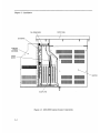
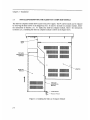
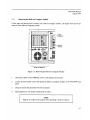
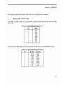
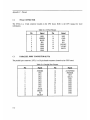
945o=ssw Softscreen Workstation PIN 99582-001A 1994 XYCOM, INC. inted in the United States of America rt Number 99582-001A XYCOM 750 North Maple Road Saline, Michigan 48 176 (3 13)429-497 1 XYCOMREVISION RECORD Revision Description Date Manual Released 8/94 ~ Trademark Information Brand or product names are registered trademarks of their respective owners. Copyright Information This document is copyrighted by Xycom Incorporated (Xycom) and shall not be reproduced or copied without expressed written authorization from Xycom. The information contained within this document is subject to change without notice. Xycom does not guarantee the accuracy of the information and makes no commitmenttoward keeping it up to date. Address comments concerning this manual to: xycom Technical Publications Department 750 North Maple Road Saline,Michigan 48 176 Part Number: 99582-OOlA XYCOMMANUAL BUG REPORT We have provided this form to track errors that may exist in our manuals and to incorporate improvements. Please describe in the space below any errors found in this manual or any helpful suggestions to improve its usefulness. To return this form, fold it in half so the postage-paid* side shows, and tape it closed. We appreciate your input and will incorporate the changes in future revisions. Current Information Page number(s): Information as currently printed: Figure number(s): Proposed Change@) Information as it should be printed: Any additional information: Address (optional) Name Title Company Address City Telephone State ZIP Xycom Use Only Log Number Date Received: Date Resolved: Manner Resolved: PCN#: Revision: 94503sW Softscreen Workstation, 99582-00114 *Ifmailingthis cardfrom outside the United States, please use an envelope with appropriate postage Void: TABLE OF CONTENTS CHAPTER TITLE 1 INTRODUCTION 1.1 1.2 1.3 1.3.1 1.3.2 1.4 Product Overview Unpacking the System System Components Front Panel Back Panel Quick Start-up PAGE 1-1 1-2 1-2 1-2 1-5 1-7 INSTALLATION 2 2.1 2.2 2.3 2.3.1 2.3.2 2.4 2.4.1 2.4.2 2.4.3 2.4.4 2.5 2.6 2.6.1 2.6.2 2.6.3 2.6.4 2.6.5 2.6.6 2.7 Introduction Preparing the System for Use InstallingRemoving the Slide-out Computer Module Removing the Slide-Out Computer Module Replacing the Slide-Out Computer Module Installing Internal Hardware Options Installation and Removal of the CPU Board Installing the 9000-RAD Card Installing the 4100-SSD Card Installing PC Boards Installing Keyboards Installing the System into a Rack or Panel Mounting Considerations System Power Excessive Heat Excessive Noise Excessive Line Voltage Mounting the 9450-SSW Derating the Power Supply 2-1 2-5 2-6 2-7 2-8 2-8 2-9 2-12 2-13 2-13 2-14 2-17 2-17 2-18 2-19 2-19 2-19 2-20 2-21 MAINTENANCE 3 3.1 3.2 3.3 3.4 Preventive Maintenance External Battery Replacement Spare Parts List Product Repair ProgrdReturning a Unit to Xycom 3-1 3-2 3-3 3-4 i Table of Contents APPENDICES A B C Technical Specifications Block Diagrams/Dimensions/Inserts Pinouts LIST OF FIGURES FIGURE TITLE 1-1 1-2 9450-SSW Front Panel 9450-SSW Back Panel 2- 1 2-2 2-3 2-4 2-5 2-6 2-7 2-8 9450-SSW Front Panel 9450-SSW Back Panel 9450-SSW Internal System Components Installing the Slide-out Computer Module Removing the Slide-out Computer Module CPU Board/Connectors 8000-KB5 Keyboard with Dimensions 8000-KB6 Keyboard with Dimensions PAGE 1-3 1-5 2-2 2-3 2-4 2-6 2-7 2-10 2-15 2-16 LIST OF TABLES TABLE TITLE 1-1 System Status LEDs 2- 1 9450-SSW Derating Example 3-1 Spare Parts List ii PAGE 1-4 2-21 3-3 Chapter 1 - INTRODUCTION 1.1 PRODUCT OVERVIEW The 9450-Softscreen Workstation (9450-SSW) combines Xycom's SoftScreen runtime engine software with the power and versatility of an IBM PC/AT-compatible computer in a package that makes sense for the factory floor and other harsh environments. The system integrates a computer card cage, mass storage, video display, solid state memory, keypads, and power supply in a truly industrial form factor. The 9450-SSW system includes a seven-slot passive backplane, an SVGA monitor, and data entry and function keypads. The front panel is sealed to NEMA 4/NEMA 12 standards, and the CRT is protected with an impact-resistant Lexan shield. The open-architecture design accepts any IBM PC, XT, or AT compatible cards. The system comes with an 80x86 CPU installed (configuration determined upon order). The processor board combines all the functions of an IBM PC/AT-compatible computer on a single, industrially-hardened circuit board. SoftScreen is embedded on Xycom's 9OOO-RAD RADAR board, so the system boots up into Softscreen. The system's "works in a module" design allows easy access to the boards, switches, and power supply. The module is easily removed by loosening three thumb screws and sliding it out. The 9450-SSW offers the following standard features: e 80x386 CPU Seven-slot PC/AT passive backplane (four full length, two Vi length and one % length AT slots) 14-inch high-resolution SVGA color monitor 32 data-entry and 20 function keys MS DOS Slide-out computer module 150-watt power supply IBM PC/AT/XT compatibility External printer port External COM1, COM2, COM3, and COM4 ports Rugged front panel sealed to meet both NEMA 4/NEMA 12 specifications when panel-mounted, and EIA 19-inch standard when rack-mounted Solid state memory board with bootable ROMs for the Softscreen Runtime System 1-1 ~~~~~~~ Chapter 1 - Introduction Optional items are also available with the 9450-SSW: Touch Screen 4100-SSD Solid state drive emulator 4100-KB2 external full-stroke keyboard 8000-KB5 panel-mount 104-key keyboard 8000-KB6 panel-mount numeric keyboard 8000-KB7 stand-alone 104-key QWERTY NEMA 4 sealed keyboard 8000-KB8 stand-alone numeric NEMA 4 sealed keyboard with 42 function keys 1.2 UNPACKJNG THE SYSTEM When you remove the 9450-SSW from its shipping carton, verify that you have the parts listed below. It is a good idea to save the box and inner wrapping in case you need to reship the unit. 9450-ssw unit Documentation kit, which includes: -Power cable -Diagnostic software diskette -16 nuts -9450-SSW user manual -Business reply card If you ordered the system with a touch screen installed, you will also receive a touch screen driver diskette, and manual. 1.3 SYSTEM COMPONENTS This section describes the components found on the 9450-SSW. 1.3.1 Front Panel The 9450-SSW comes equipped with a NEMA 4/NEMA12 sealed front panel. The panel protects the system's interior when the system is properly panel mounted. See Section 2.6 for rack- and panel-mounting instructions. Figure 1-1 illustrates the front panel features of the 9450-SSW. 1-2 94.50-SSW Manual August I994 DATA ENTRY KEYPAD LEXAN SHIELD AND DISPLAY SYSTEM STATUS LEDS \ f FUNCTION KEYS ACCESS DOOR LATCH (F1-F20) Figure 1-1. 9450-SSW Front Panel 1-3 Chapter 1 - Introduction Monitor Protected from breakage by an impact-resistant Lexan shield, the 14" monitor supports a high-resolution SVGA color. If a touch screen is installed, the Lexan shield will be replaced by safety glass backed touch panel. Function Keys These 20 keys-located directly below the monitor-provide the user with easy access to routines configured in the SoftScreen application. Access Door Located below the data entry keypad, this door accesses the keyboard port. The keyboard port allows a PC/AT keyboard to be interfaced with the system. Touch Screen Xycom' s touch screen-an optional feature configured in the SoftScreen application-is based on resistive membrane technology and consists of two thin sheets of polycarbonate with transparent, conductive coatings on the facing sides. Finger or stylus pressure causes the outer sheet to make electrical contact with the inner sheet. Xycom' s touch screen complies with complete environmental specifications and remains operational even after two million touches. Data Entry Keypad This 32-key numeric keypad includes 15 data entry keys; the up, down, left, and right arrows; and numbers 0-9. All keys on the keypad are programmable and the top 15 are relegendable. System Status LEDs During power-up, the CPU board checks its hardware configuration against the configuration information stored in the CMOS memory. If the power-up self-test (POST) is successful, the MAINT and FAULT LEDs will be off. Table 1-1. System Status LEDs I I I 1-4 I I I I Fault Maint Power Radar Off off Off Off No power off Off on Off System in reset prior to post off on on off Running POST on Off on off Failed POST off off I I off off I I on on I I off on Condition I Passed POST (RADAR off) I Passed POST (RADAR on) off on on on RADAR Maintenance on off on on RADAR Fault 9450-SSW Manual August I994 1.3.2 Back Panel Figure 1-2 illustrates the features of the back panel components of the 9450-SSW. OPTIONAL TOUCH SCREEN ADAPTER TOUCH SCREEN (OPTIONAL) REAR KEYBOARD PRODUCT I.D. LABEL I SPEAKER I 0 0 0 \ COM 3 PARALLEL PORT + / J "- OCI OE RELAY I\& POWER SWITCH I I llllllllllllle33 I ll 11111111111 FAN lo I 0e oa 0 L POWER SVGA VERTICAL SIZE HORIZONTAL POSITION VERTICAL POSITION CONTRAST _I BRIGHTNESS PWR/KEY SLIDE-OUT MODULE Figure 1-2. 9450-SSW Back Panel 1-5 Chapter 1 - Introduction On/Off Switch This switch should be positioned to Off (switch should be out) until the system is properly configured and connected to a 115 VAC or 230 VAC power source. Power Receptacle The power receptacle is located to the right of the OdOff switch. The upper power outlet is for the monitor and the lower power outlet is for the main power source. The plug and cord for the AC power and the monitor power must be securely positioned before turning power on. Video Connector The 15-pin high density video cable is connected to the SVGA port on the CPU. Video Controls The contrast and brightness controls are located on the right side of the unit. Turning the knobs left or right adjusts contrast or brightness on the monitor. The vertical size, horizontal position, and vertical position are located above the contrast and brightness controls. Turning the knobs left or right adjusts the vertical position, horizontal position, and vertical height. Parallel Port The DB-25 female parallel port connector and is located on the CPU board for all configurations. NOTE The pinouts for connectors and ports are shown in Appendix C. PWR/Key This 15-pin dual row DB connector provides the power, keyboard, and LED signals to the front keypad controller board. COM Ports The COM ports are DB-9 male connectors. COMl and COM24ocated on rear housing-are RS-232C. COM3 and COM4-located on the 9OOO-RAD board-can be RS-232C or RS-485. External Battery The 9450-SSW has an external battery located to the right of the P W K e y connector. To replace the battery, use a screw driver to remove the battery bracket screw. Pull the bracket out. Disconnect the battery connector and remove the battery from the Velcro hold-down. Replace it with a new battery and reconnect the battery cable. Slide the battery into unit. Replace and the tighten screw. Rear Keyboard There is a PC/AT keyboard connector on the rear of the 9450-SSW. Both front and rear keyboards can be connected simultaneously. 1-6 9450-SSW Manual August 1994 Touch Screen (optional) The optional touch screen cable has a 9-pin DB connector which is attached to the connector on the touch screen adapter board located in Slot 5 . Relay The relay connector-located on the 9000-RAD board-is software enabled and disabled. This is configured in the Softscreen application. It can also be optionally relaxed through the use of a switch when the watchdog timer expires. The relay contacts are isolated to 500V. 1.4 QUICK START-UP NOTE Xycom recommends you ut leust read this section and the appendices. This section gets your 9450-SSW up and running without explaining the capabilities and options of the system. The appendices provide technical specifications, diagrams, and other information required for system operation. To prepare the system for use, perform the steps listed on the following pages. WARNING Turn off the power to the unit and unplug the power cord before making any adjustments to the inside or outside of the computer. WARNING If the battery is disabled, when it is re-enabled the system must be powered up for a minimum of 30 seconds. Failure to follow this procedure may result in premature battery failure. NOTE If a touch screen has been factory installed, there is an AT adapter board plugged into the backplane in slot 5 . Connect the 9-pin cable from the monitor side to the 9-pin connector in slot 5 . 1-7 Chapter 1 - Introduction Connect the video cable to the 15-pin connector on the CPU board. 2. Connect the P W K e y 15-pin cable to the P W K e y female receptacle located above the power receptacle. 3. Attach any other optional equipment. 4. Attach the monitor power cord from the monitor to the power receptacle. Attach the power cord power receptacle to a properly grounded 115/230 VAC, 50/60 Hz outlet. Attach the power cord to the lower power receptacle 5. Connect the 9-pin DB connector which is attached to the touch screen adapter board located in slot 5 (optional feature). 6. T u r n on power to the unit by pressing the On/Off switch in. The system will boot up to the Softscreen Runtime Engine window. 7. Set the contrast and brightness controls on the back panel to the desired levels 8. Download a Softscreen application. Refer to the Softscreen Development System Manual for more information. 1-8 ~~ Chapter 2 - INSTALLATION 2.1 INTRODUCTION This chapter discusses how to install options into the 9450-SSW.The figures on the next several pages show the internal and external components on the front and back panels of the unit to help you locate features relevant to installation. 2-1 Chapter 2 - Installation DATA ENTRY KEYPAD LEXAN SHIELD AND DISPLAY SYSTEM STATUS LEDs I I FUNCTION KEYS ACCESS DOOR LATCH (Fl-F20) Figure 2-1. 9450-SSW Front Panel 2-2 94.50-SSW Manual August 1994 OPTIONAL TOUCH SCREEN ADAPTER SPEAKER TOUCH SCREEN (OPTIONAL) REAR KEYBOARD PRODUCT I.D. LABEL I I 0 4 I COM 3 PARALLEL PORT COM 4 OE SVGA OE OP IN \ d 0 \ \ HORIZONTAL POSITION VERTICAL POSITION 0 0 I I lllllllllllll O D I ll lllllllllll I VE RTlCAL SIZE 0 CONTRAST P BRIGHTNESS O I I POWER SVGA PWRIKEY SLIDE-OUT MODULE Figure 2-2. 9450-SSW Back Panel 2-3 . Chapter 2 - Installation , i FAN POWER WIRE CPU BOARD 6 \ I I SLIDE-OUT MODULE TOP (OPEN) RADAR BOARD - ' MONKOR BACKPLANE Figure 2-3. 9450-SSW Internal System Components 2-4 9450-SSW Manual August 1994 2.2 PREPARING THE SYSTEM FOR USE To prepare the system for use, perform the steps listed below. If you purchased any options, install them according to the instructions in the next two sections. 1. Connect the video cable to the 15-pin connector on the CPU board. 2. Connect the PWWKey 15-pin cable to the PWR/Key female receptacle located above the power receptacle. 3. Attach any other optional equipment. 4. Attach the monitor power cord from the monitor to the power receptacle. Attach the power cord power receptacle to a properly grounded 115/230 VAC, 50/60 Hz outlet. Attach the power cord to the lower power receptacle 5. Connect the touch screen. See note below. NOTE If a touch screen has been factory installed, there is an AT adapter board plugged into the backplane in slot 5. Connect the 9-pin cable from the monitor side to the 9-pin connector in slot 5. 1 6. Turn on power to the unit by pressing in the ordoff switch. The system will boot up to the Softscreen Runtime Engine window. 7. Set the contrast and brightness controls on the back panel to the desired levels. 8. Download a SoftScreen application. Refer to the Softscreen Development System Manual for more information. 2-5 Chapter 2 - Installation 2.3 INSTALLING/REMOVING THE SLIDE-OUT COMPUTER MODULE The slide-out computer module allows access to the power supply. The PC add-in boards can be replaced by removing the three screws on the hinged top cover. To remove the slide-out computer module, follow the instructions in Section 2.3.1. To replace the slide-out computer module, follow the instructions in Section 2.3.2. Installing the slide-out computer module is shown in the figure below. lf 1lll111111 1111111 l1 11 l111111 1ll1l1111 TOP SLIDE (MOUNTEDON MONITOR) O \ SLIDE-OUT MODULE I 1 111111111111110, ll111lllll 1111111 l1 1ll11111 l1111l11 TOP SLIDE (MOUNTEDON MODULE) w THUMB SCREW MODULE HANDLE Figure 2-4. Installing the Slide-out Computer Module 2-6 ‘ MONITOR 9450-SSW Manual August 1994 2.3.1 Removing the Slide-out Computer Module Follow steps one through four to remove your slide-out computer module. The figure below shows the removal of the slide-out computer module. 0 0 1 _L\ THUMB SCREW(3) MODULE HANDLE al__ 0 0 I SLIDE-OUT MODULE Figure 2-5. Removing the Slide-Out Computer Module 1. Disconnect cables (VGA, PWRKey, Power, and optional touch screen), 2. Loosen the three thumb screws that attach the slide-out computer module to the 9450-SSW back panel. 3. Grasp the handle that protrudes from the back panel. 4. Pull straight back. The module should slide-out easily. NOTE Support the weight of the module when separating it from the chassis. 2- 7 Chapter 2 - Installation 2.3.2 Replacing the Slide-out Computer Module After you have f ~ s h e dinstalling options on your 945O-SSW, reconnect it to the front panel according to the instructions below: 1. Match the top and bottom guides on the module with the slider indentations on the side of the monitor module shell, as illustrated in Figure 2-4. 2. Push forward firmly until the top and bottom of the module are flush with the top and bottom of the front panel shell. 3. Tighten the three thumb screws removed earlier (see Figure 2-5). 4. Reconnect all cables (SVGA, PWR/Key, power, and optional touch screen). 2.4 INSTALLING INTERNAL HARDWARE OPTIONS CAUTION The unit must be turned off before installing internal hardware. Internal hardware options may be installed through the hinged cover with the module in place. Certain mounting configurations require the slide-out computer module to be removed (refer to Section 2.3.1 for details). 2-8 ~~ ~ 9450-SSW Manual August I994 2.4.1 Installation and Removal of the CPU Board This section describes the steps required to install and remove the CPU board. WARNING Disconnect all external power supplies before you open and service any piece of equipment. Also, always use static protection when handling CPU boards. WARNING If the battery is disabled, when it is re-enabled the system must be powered up for a minimum of 30 seconds. Failure to follow this procedure may result in premature battery failure. CAUTION Verify the positions of all jumpers and switches before installation. Check configurations with the lists and diagrams in this manual. NOTE Before connecting a ribbon cable to latched connectors, make sure the latches are pulled halfway down. When the cable connection is made, the latches snap up. When removing a cable connector, pull the latches down near the board. This ejects the connector so you can remove it easily. 2-9 Chapter 2 - Installation CPU BOARD (PARTIALLY WITHDRAWN) LED FDD HDDl COM 1 COM 2 BAT-IN [OPTIONAL 9450-625(X) ONLYl 4COVER FRONT PANEL (OPEN) \ SLIDE-OUT COMPUTER MODULE Figure 2-6. CPU Board/Connectors 2-1 0 9450-SSW Manual August 1994 Removing the CPU Board 1. Disconnect all power supplies 2. Remove the three screws that secure the top cover to the slide-out computer module. Certain mounting configurations require the slide-out computer module to be removed. (Refer to Section 2.3.1 for details.) 3. Remove and save the CPU board ORB screw. 4. Unseat the CPU board from the backplane. Pull the board upward far enough to unlatch and remove connectors (about one inch). 5. Remove cable connectors FDD, HDD-I, COM1, COM2, LED, and BAT-IN. 6. Now that the cables are disconnected, pull the CPU board out of the slide-out computer module. Installing the CPU Board 1. Disconnect all power supplies 2. Remove the three screws that secure the top cover to the slide-out computer module. Certain mounting configurations require the slide-out computer module to be removed (refer to Section 2.3.1 for details). 3. Verify all jumper settings. 4. Hold cables FDD, HDD-I, COM1, COM2, and LED toward the side of the CPU module. 5. Place the 9450-SSW CPU card into slot 0 in the passive backplane. Push the card % ofi the way down. Figure 2-5 shows slot 0. 6. Attach flat cables FDD, HDD-I, COMl , COM2, and LED to the respective connectors on the CPU board. Push down the card evenly until it firmly seats into the card edge connector. 7. Connect the battery cable connector BAT-IN to the CPU board. (This cable is optional.) 2-11 Chapter 2 - Installation 8. Secure the ORE3 with one screw at the top. 9. Close the top cover and replace and tighten the three screws. If the slide-out computer module in the 9450-SSW was removed in Step 2, see Section 2.3.2 for re-installation details. 10. Connect all power sources previously disconnected. The 9450-SSW CPU is now ready for operation. 2.4.2 Installing the 9000-RAD Card Before installing the 9000-RAD into the 945O-SSW, jumpers and switches must be set for your particular configuration. See the Softscreen PC/AT Engine Manual for more information. After the 9000-RAD card is properly configured, it can be installed into the 9450-SSW card cage as follows: 1. Unplug the 9450-SSW from the AC wall outlet. 2. Remove the three screws on the top cover and open. Certain mounting configurations require the slide-out computer module to be removed (refer to Section 2.3.1 for details). 3. If present, remove the blank ORB from the slot that the 9000-RAD will occupy. Save the screw. 4. Slide the RADAR card into an open slot in the backplane. Push down on the card evenly until it firmly seats into the card cage connectors. NOTE DO NOT force the boards or apply uneven pressure. 5. Secure the RADAR ORB to the host system by replacing and tightening the screw that was removed in Step 3. 6. Close the top cover and replace and tighten the three screws. If the slide-out computer module in the 9450-SSW was removed in Step 2, see Section 2.3.2 for re-installation details. 2-12 94.50-SSW Manual August I994 Installing the 4100-SSD Card 2.4.3 Before installing the 4100-SSD (Solid State Disk) board into the 945O-SSW, jumpers and switches must be set for your particular configuration. See your 4100-SSD manual for more information. After the 4100-SSD is properly configured, it can be installed into the 9450-SSW card cage as follows: 1. Unplug the 9450-SSW from the AC wall outlet. 2. Remove the three screws on the top cover and open. Certain mounting configurations require the slide-out computer module to be removed (refer to Section 2.3.1 for details). 3. Verify all jumper and switch settings. Refer to the 4100-SSD manual for the correct settings. 4. If present, remove the blank ORB from the slot (1, 2, or 3 ) that the 4100-SSD card will occupy. Save the screw. 5. Slide the SSD card into an open slot in the backplane. Push down on the card evenly until it firmly seats into the card cage connectors. NOTE DO NOT force the boards or apply uneven pressure. 6. Secure the SSD ORB to the host system by replacing the screw that was removed in Step 4. 7. Close the top cover and replace and tighten the three screws. If the slide-out computer module in the 9450-SSW was removed in Step 2, see Section 2.3.2 for re-installation details. 2.4.4 Installing PC Boards Check that the memory and I/O configuration of the board you want to install does not conflict with the CPU and I/O memory maps in your CPU board manual. 1. Unplug the 9450-SSW from the AC wall outlet. 2. Remove the three screws on the top cover and open. Certain mounting configurations require the slide-out computer module to be removed (refer to Section 2.3.1 for details). 3. If present, remove the blank ORB from the slot that the PC board will occupy. Save the screw. 2-13 Chapter 2 - Installation 4. Slide the PC board into an open slot in the backplane. Push down on the board evenly until it firmly seats into the card cage connectors. NOTE DO NOT force the boards or apply uneven pressure. 5. Secure the board by replacing and tightening the screw that was removed in Step 3. 6. Close the top cover and replace and tighten the three screws. If the slide-out computer module in the 9450-SSWwas removed in Step 2, see Section 2.3.2 for re-installation. 2.5 INSTALLING KEYBOARDS Four keyboards are available for the 9450-SSW: the 8000-KB5,8000-KB6, 800O-KE37, and 8000-KE38. The features of each keyboard are listed below: ~~ ~ o u t e d NEMA 4 numeric keyboard The 80o0-KB5 and 80o0-KB6 are installed in the same manner (dimensions are shown in Figures 2-7 and 2-8). Mount them according to the cutout in Appendix B. Once the keyboard is mounted, connect the keyboard cable to the keyboard port on the back panel of the unit. The stand-alone 8000-KB7 and 8000KB8 keyboards each use a standard keyboard connector. 2-14 9450-SSW Manual August 1994 y _ j b_ I 19.00" Depth = 0.25" Figure 2-7. 8000-KE35 Keyboard with Dimensions 2-15 _ _ _ _ ~ ~ ____________ ~~ ~ Chapter 2 - Installation I 9.72" Depth = 0.25" Figure 2-8. 8000-KJ36 Keyboard with Dimensions 2-16 9450-SSW Manual August 1994 2.6 INSTALLING THE SYSTEM INTO A RACK OR PANEL The 9450-SSW's rugged design allows it to be installed in most industrial environments. The 9450-SSW is generally placed in a NEMA 4/12 enclosure to protect against contaminants such as dust, moisture, etc. Metal enclosures also help minimize the effects of electromagnetic radiation that may be generated by nearby equipment. Follow the guidelines below for installing your 9450-SSW. 2.6.1 Mounting Considerations Once you have found a location for the 945O-SSW, install it in the enclosure according to the manufacturer's instructions. Consider the following points and precautions before placing the 9450-SSW inside an enclosure: Select an enclosure that will allow access to the 9450-SSW ports and slide-out computer module. Account for the unit's depth, as well as cabling, when choosing the depth of the enclosure. Mount the 9450-SSW in an upright position. Place the 9450-SSW at a comfortable working level. Consider locations of accessories such as AC power outlets and lighting (interior lighting and windows) for installation and maintenance convenience. If condensation is expected, install a thermostat-controlled heater or air conditioner To allow for maximum cooling, avoid obstructing the air flow. Place any fans or blowers close to the heat generating devices. If using a fan, make sure that outside air is not brought inside the enclosure unless a fabric or other reliable filter is used. This filtration prevents conductive particles or other harmful contaminants from entering the enclosure. Do not select a location near equipment (such as high power welding machines, induction heating equipment, and large motor starters) that generates excessive electromagnetic interference (EMI) or radio frequency interference (RFI). 2-1 7 Chapter 2 - Installation Place incoming power lines (such as isolation or constant voltage transformers, local power disconnects, and surge suppressors) away from the 9450-SSW. The proper location of incoming line devices keeps power wire runs as short as possible, and minimizes electrical noise transmitted to the 9450-SSW. Make sure the location does not exceed the 9450-SSW's temperature specifications. NOTE The displays may be affected by Geomagnetic fields. Typical effects of magnetic fields are purity (blotchy colors), distorted screens, etc. In some cases, purity problems may be corrected by turning off the unit for 30 minutes and then reapplying power. In other cases a degaussing wand may be needed. Contact Xycom's Customer Service Department for further information. 2.6.2 System Power It is always a good idea to use isolation transformers on the incoming AC power line to the 9450-SSW. An isolation transformer is especially desirable in cases in which heavy equipment is likely to introduce noise onto the AC line. The isolation transformer can also serve as a step-down transformer to reduce the incoming line voltage to a desired level. The transformer should have a sufficient power rating (units of volt-amperes) to supply the load adequately. Proper grounding is essential to all safe electrical installations. Refer to the National Electric Code (NEC), article 250, which provides data such as the size and types of conductors, color codes and connections necessary for safe grounding of electrical components. The code specifies that a grounding path must be permanent (no solder), continuous, and able to safely conduct the ground-fault current in the system witn minimal impedance. The following practices should be observed: Separate ground wires from power wires at the point of entry to the enclosure. To minimize the ground wire length within the enclosure, locate the ground reference point near the point of entry for the plant power supply. Ground all electrical racks or chassis and machine elements to a central ground bus, normally located near the point of entry for the plant power supply of the enclosure. Paint and other nonconductive material should be scraped away from the area where a chassis makes contact with the enclosure. In addition to the ground connection made through the mounting bolt or stud, a one-inch metal braid or size #8 AWG wire can be used to connect between each chassis and the enclosure at the mounting bolt or stud. 2-1 8 9450-SSW Manual August 1994 Properly ground the enclosure to the ground bus. Make sure a good electrical connection is made at the point of contact with the enclosure. Connect the machine ground to the enclosure and to earth ground. 2.6.3 Excessive Heat The 9450-SSW is designed to withstand temperatures form Oo to 5OoC and is cooled by convection, in which a vertical column of air is drawn in an upward direction over the surface of the components. To keep the temperature in range, the cooling air at the base of the system must not exceed 50OC. Proper spacing must also be allocated between internal components installed in the enclosure. When the air temperature is higher than 5OoC in the enclosure, use a fan or air conditioner. 2.6.4 Excessive Noise Electrical noise is seldom responsible for damaging components, unless extremely high energy or high voltage levels are present. However, noise can cause temporary malfunctions due to operating errors, which can result in hazardous machine operation in certain applications. Noise may be present only at certain times, may appear at widely-spread intervals, or in some cases may exist continuously. Noise usually enters through input, output, and power supply lines and may be coupled into lines electrostatically through the capacitance between these lines and the noise signal carrier lines. This usually results from the presence of high voltage or long, closed-spaced conductors. When control lines are closely spaced with lines carrying large currents, the coupling of magnetic fields can also occur. Use shielded cables to help minimize noise. Potential noise generators include relays, solenoids, motors, and motor starters, especially when operated by hand contacts like push buttons or selector switches. In accordance with National Electric Code specifications, it is recommended that high voltage and low voltage cabling be separated and dressed apart. In particular, the AC cables and switch wiring should not be in the same conduit with the PLC communication cables. 2.6.5 Excessive Line Voltage The power supply section of the 9450-SSW is built to sustain line fluctuations of 90-131 VAC or 182-226 VAC and still allow the system to function within its operating margin. As long as the incoming voltage is adequate, the power supply provides all the logic voltages necessary to support the processor, memory, and I/O. 2-19 Chapter 2 - Installation In cases in which the installation is subject to unusual AC line variations, a constant voltage transformer can be used to prevent the system from shutting down too often. However, a first step toward the solution of the line variations is to correct any possible feed problem in the distribution system. If this correction does not solve the problem, a constant voltage transformer must be used. The constant voltage transformer stabilizes the input voltage to the 9450-SSWby compensating for voltage changes at the primary to maintain a steady voltage at the secondary. When using a constant voltage transformer, check that the power rating is sufficient to supply the 9450-SSW. 2.6.6 Mounting the 9450-SSW Once the conditions in the preceding sections have been met, mount the 9450-SSW by following the instructions below: 1. Locate a position for your 9450-SSWthat meets the specifications required (see previous sections and Appendix A). 2. Add the cutout (as shown in Appendix B, Figure B-6) to the enclosure. 3. Make sure the area around the cutout is clean and free from metal burrs. 4. Make sure the 9450-SSWenclosure is grounded to the enclosure. 5. Detach the slide-out computer module (see Section 2.3.1). 6. Install the monitor portion of the unit into the cutout. 7. Reattach the slide-out computer module (see Section 2.3.2). 8. Tighten the 14 #10 nuts to 27 inch pounds. 2-20 94.50-SSW Manual August 1994 2.7 DERATING THE POWER SUPPLY The power supply is 200 watts derated to 150 watts of power at 5 O O C . Refer to Table 2-1 for more information. Table 2-1. 9450-SSW Derating Example +5vDc Total Current Available Before Derating (not to exceed 150 W) 9450-SSW Configured Current Required: AT4SLC +/AT4 + 2.6013.75 A SRAh4 Touch screen controller (serial) Fan Keyboard 9000-RAD card Total (maximum) 9450-SSW Exuansion Current Available Example: 9450-SSW w/AT4SLC 4.07Ax5V 0.72Ax 12V .05Ax 12V = = = 20A I +12vDc -12vDc -5vDc 8A 0.50 A 0.50 A .05 A 0 0 0 0 0 0 0.50 A 0.25 A 0.25 A 0 0.40 A 0.80 A 4.3015.45A 0.26 A 0 0.23 A 0.99 A .05 A 0 0 0 0 0 0.05 A 14.55115.70 A 7.01 A 0.45 A 0 0 0 + 21 S O watts 11.88 watts 0.60 watts 33.98 watts total 150w - 3 3 . 9 8 ~= 116.02 watts 116 watts available for expansion cards 2-21 Chapter 3 - MAINTENANCE 3.1 PREVENTIVE MAINTENANCE The 9450-SSWis designed to withstand the harsh environment of the factory floor. Routine maintenance can help keep your 9450-SSW in good operating condition. Preventive maintenance consists of several basic procedures and checks that will greatly reduce the chances of system malfunction. Preventive maintenance should be scheduled along with the regular equipment maintenance to minimize 9450-SSW down time. Some preventive measures are listed below: Remove dust and dirt from PC components. If dust builds up on heat sinks and circuitry, an obstruction of heat dissipation could cause the unit to malfunction. If dust reaches the electronic boards, a short circuit could occur. Check the connections to I/O modules, especially in environments where shock could loosen the connections. Check to see that all plugs, sockets, terminal strips, and module connections are solid. Remove unnecessary articles, like drawings or manuals, from the unit. They could obstruct air flow and create hot spots, which cause the system to malfunction. Do not move noise generating equipment near the 9450-SSW. Stock spare parts to minimize down time resulting from part failure. The spare parts stocked should be five percent of the number of each unit used. CPU cards should have one spare each, regardless of the number of CPUs used. Each power supply should have a back-up. In certain applications where immediate operation of a failed system is required, an entire spare module may need to be stocked. When replacing a module, make sure it is the correct type. If the new module solves the problem, but the failure reoccurs, check for inductive loads that may be generating voltage and current spikes and may require external suppression. 3-1 Chapter 3 - Maintenance 3.2 EXTERNAL BATTERY REPLACEMENT The 9450-SSWhas an external battery located on the back panel. To replace the battery, use a screw driver to remove the battery bracket screw. Pull the bracket out. Disconnect the battery connector and remove the battery from the Velcro hold-down. Replace it with a new battery (refer to the spare parts list for battery part number) and reconnect the battery cable. Slide the battery into the unit. Replace and tighten the screw. CAUTION DANGER OF EXPLOSION IF BATTERY IS INCORRECTLY REPLACED. Replace only with the same or equivalent type recommended by the manufacturer. Dispose of used batteries according to the manufacturer's instructions. Bei falschem Umgang mit odor falschem Einbau einer Lithium-Batterie kann eine Explosion entstehen, bel der in der Nahe befindliche Personen schwere Verietzungen erieiden konnen. Versuchen Sie nicht, Lithium-Batterien wieder aufzuiaden, kurzzuschliessen oder zu ottnen, und werfen Sie sie nicht in den Mull oder in ein Feuer. Wechsein Sie sie nur gegen gensu den gleichen Typ aus. Zur entsorgung mussan Sie Lithium-Batterien an ihren Handler zuruckgeben. 3-2 9450-SSW Manual August I994 3.3 SPARE PARTS LIST Use the part numbers specified below when reordering parts for your 9450-SSW unit. Description Xycom Part Number ~~ 9000-RAD card 99384-002 Blank ORB 9 1824-001 CPU + AT4SLC , 0 Mbytes AT4SX, 0 Mbytes AT4DX, 0 Mbytes AT4DX2,O Mbytes 99 142-025 99298-133 99298-233 99298-266 4 Mbytes x 9 1 Mbytes x 9 98749-00 1 98012-001 DRAM External battery, Lithium 3.6V 98782-001 Keyboard Interface Module 992 13-00 1 Lexan shield 94 157-001 Power cord 88760-00 1 Power Supply 99377-001 Touch screen controller 99410-001 3-3 PRODUCT REPAIR PROGRAM/RETUR"G A UNIT TO XYCOM 3.4 Xycom's Product Repair Service restores equipment to normal operating condition and implements engineering changes that enhance operating specifications. Products returned to Xycom will be tested with standard Xycom test diagnostics. Contact the Product Repair & Customization (PR&C) department at 1800289-9266. Perform the following steps to prepare the unit for shipment: Obtain an RMA number for the unit by calling your local Product Repair Department or Xycom repair center. Have the following information ready: Company name and shipping and billing address Type of service desired: product repair or product exchange Product model number, part number, quantity, serial number(s), and warranty status Failure mode and failure systems Purchase order number or repair order number . You will then receive an RMA number. This number must appear on the outside of the shipping container and on the purchase order. To prepare the 9450-SSW for shipment, make sure the front panel assembly is properly attached to the unit and the slide-out computer module is secured by all three fasteners. To speed processing, attach any failure information to the unit. Place the unit securely in a heavy-duty box. Mark the RMA number on the outside of the box as well as on your purchase order Send the unit to your local Xycom repair center. 3-4 ~~~~ Appendix A - TECHNICAL SPECIFICATIONS A.1 SPECIFICATIONS The specifications for the 9450-SSW are listed in the following tables: Table A-1. 9450-SSW lardware Specifications Characteristic Specification Mechanical Height Width Depth Weight 12.2" (310 mm) 19" (483 mm) 16.5" (419 mm) 59 lbs (26.7 kg) Electrical 115/230 VAC 14 to 21% 50-60 Hz, 300 watts Power Supply 150 Watts Backplane Seven-slot AT passive backplane (7 AT slots) 150 watts available to backplane/drives +5 V @ 20 A/ 12 V @ 8 A -5 V and -12 V: .5 A total Mounting EIA Standard 19" rack or an el Monitor Compatibility CRT Size Resolution Dot trio Ditch SVGA 14" 640 x 480, 800 x 600, 1024 x 768 (interlaced) 0.28 mm A-1 Appendix A - Technical Specifications Table A-2. 9450-SSWEnvironmental Specifications Operating Altitude A-2 Appendix B - BLOCK DIAGRAMS/DIMENSIONS/INSERTS 1- Rear Panel 9 99286-001 I KYBD-IN1 I KEYPAD 32-POSITION 99104-001 -FUNCTION KEYPAD 20-POSITION ? 99237-001 - -- I AT.BUS TOUCH SCREEN OPTION __---______________________ I c z -- HKEYBD. CONN. I POWER SWlTCH A om" I From Panel 99287-001 - UII I m I I I $ $ _f -e e I I z z --+Kii+$ $ 2 2 -- TOUCH SCREEN 98551-002 I 70 0 g g -- 99308-001 h KEYBOARD INTERFACE MODULE 99222-001 REAR PANEL G G I P2 1 1 P1 1 1 I DC-INPI I DC-IN11 I -o n r Y Y -- - :-0 - 8T V 99309-001 -2%-0 0 --$ -v v $ CPU BOARD --- FAN FAN I I BACKPLANE 99226-001 9000-RAD 1 MONITOR 14 INCH VGA 99437-001 N m % 5 - BATOUTO 1 I VGA I IBAT.IN~ Figure B-1 . System Block Diagram B-1 Appendix B - Block Diagrams/Dimensions/Inserts Material: NOTE .010 thick Aluminum with .090 thick domes. Epoxy resin in the front side and 3M #468 adhesive on the back side. Radius= .042" 70.83" L Figure B-2. 9450-SSW Logo Dimensions B-2 94.50-SSW Manual August I994 NOTE Material: .010 thick textured polyester overlay resin on the front side and 3M #467 adhesive on the back side. Character coloc = PMS-420U (light gray) Helvetica medium font, .25" height .094"R &>ound coloc = PMS-426U (charcoal gray .455" 7 I I = PMS-285U (medium blue) .062R pi] [E] [K] [E] [GI c-. 1.530" .620" [K] [R][fi) (F20) [E] -- I -b 4 I 1 .OOO"typ. --*j non-accum. 9.000" 12.270" 1 1.635" -D C Material: .010" overlay (8 mil TEXTURED POLYESTER AUTOTEX V8) (2 mil 3M #467 adhesive) Figure B-3. 9450-SSW 20 Function Key Overlay B-3 (1 Appendix B - Block DiagramdDirnensiondInserts Material: .03R 2places NOTE ,007 thick polyester with factory clear hardcoat on the front side and U V velvet on the back side. 1+ 0.625" typ. non-accum. 0.625" ty p . non-accum. ESC SHIFT '6FE HOME END INSERT PAUSE + i T BACK SPACE - I CTRL SPACE ALT DEL I 1.850" iL ~ Notes: Material: .007" thick polyester with factory clear hardcoat on top side. Crease insert approximately at the dotted line. Then bend downward to approximately 90". Crease must not be so sharp as to fracture part. Figure B-4. 9450-SSW 15-Key Insert B-4 9450-SSW Manual August 1994 t 19.00 (483) 4- 8.72 7.96 (202) + ,3.1 65 (80.2) 6.00 (152) b 6.00 (1 52) b4 +- 3.156(80.2) B 17.100 (434)______) tI Torque 10-32mounting nuts to 25 inch-lbs. (2.8Nm) (28Kgf cm) 7.00 (1 78) I LY i (50.3) 0 s ‘.25(6.35) 0 diameter holes f.48 (12. + k . 6 1 (15.5 I 18.312 (465) All dimensions are in inches (mm) Depth: 0.25 (6.35) Figure B-5. 8000-KB5 and 8000-KB6 Keyboard Cutout Dimensions B-5 Appendix B - Block Diagram/Dimensions/Inserts 0.25 (6.35)diam. hole (14req'd) 3.1 56 0.23 (5.84) 6.00 (152.4) I 3.50 (88.90) 4 17.625 (447.68) 3 2.25 (57.15) i. 1 1.45 390.83) Torque 10-32 mounting nuts to 25 inch-lbs. (2.8 Nm) (28 Kgf cm) 3 11.OO $79.40) 3.50 (88.90) C 0 18.312 (465.12) ' All dimensions are in inches (mm) Depth: 19.00 (482.60) (lndudescable clearance) Figure B-6. 94.50-SSW System Cutout Dimensions B-6 t (5.84) I 0.23 I Appendix C - PINOUTS This appendix describes the pinouts for the COM, SVGA, and parallel port connectors. c .1 SERIAL PORT CONNECTORS The COMl and COM2 serial ports are standard DB-9 connectors located on the I/O side of the unit on the CPU board. Table C-1. COMl/COM2 Serial Port Pinouts I Pin Signal 1 2 3 4 5 6 7 DCD RXD TXD DTR GND DSR RTS CTS 8 9 I RT The COM3 and COM4 serial ports are located on the I/O side of the unit on the 9000-RAD board. Table C-2. CC ui3/COM4 Sei I Port Pinouts Pin RS-232C RS-485 1 2 3 4 DCD RXD TXD DTR GND DSR RTS CTS TXDTXD + RTSRTS + GND RXDRXD+ CTS + CTS- 5 6 7 8 9 RI c-I Appendix C - Pinouts c.2 SVGA COMVECTOR The SVGA is a 15-pin connector located on the CPU board. Refer to the CPU manual for more information. Table C-3. SVGA Pinouts c.3 Pin Signal Pin Signal 1 2 3 4 5 6 7 8 RED GREEN BLUE ID2 GND GND GND GND 9 10 11 12 13 14 15 KEY GND ID0 ID 1 HSYNC VSYNC RSVD PARALLEL PORT CONNECTOR (LPT1) The parallel port connector, LPT1, is a 25-pin female connector located on the CPU board. c-2 Pin Signal Pin Signal 1 2 3 4 5 6 7 8 9 10 11 12 13 STROBE PDO PD 1 PD2 PD3 PD4 PD5 PD6 PD7 PACK PBUSY PE SELECT 14 15 16 17 18 19 20 21 22 23 24 25 AUTOFEED PERROR INIT SELIN GND GND GND GND GND GND GND GND 9450-SSW Manual August 1994 C.4 KEYBOARD CONNECTORS Two standard five-pin keyboard connectors are available on the 9450-SSW. Figure C-1 illustrates the location of the pins. Figure C-1 . Keyboard Connector Pin Location (Front View) Table C-5. Kevboard PidSimal c.5 Pin Signal 1 2 3 4 5 Clock Data NC GND +SVDC SPEAKER JACK The speaker jack is a subminiature phone jack located on the CPU board. Refer to the CPU manual for more information. Pin Signal Tip Sleeve Sources Current GND c-3 INDEX Numerical F 4100-SSD, installation 2-13 9000-RAD, installation 2-12 Features, standard 1-1 Front panel 1-2, 2-2 Function keys 1-4 A Access door 1-4 H B Hardware specifications A-1 Heat, excessive 2-19 Back panel 1-5, 2-3 Battery, external 1-6 Block diagram B-1 C COM pinouts C-1 Components Back panel 1-5, 2-3 Front panel 1-3, 2-2 Internal 2-4 Connectors COMl/COM2 1-6, C-1 COM3/COM4 1-6, C-1 Keyboard 1-6, C-3 Parallel port 1-6, C-2 Relay 1-7 Speaker jack C-3 SVGA 1-6, C-2 Touch screen 1-7 Controls, video 1-6 CPU board Installation 2-11 Removal 2-11 I Insert, 15-key B-4 Installation 2-1 4100-SSD card 2-13 9000-RAD card 2-12 CPU board 2-11 Internal hardware options 2-8 Keyboards 2-14 Panel 2-17 PC boards 2-13 Rack 2-17 K Keyboard Dimensions 2-15, 2-16 Installation 2-14 Pinouts c-3 Rear 1-6 Keys Data entry 1-4 Function 1-4 L D Data entry keypad 1-4 Derating, power supply 2-21 Dimensions Keyboard cutout B-5 Keyboards 2-15, 2-16 Logo B-2 System cutout B-6 E Environmental specifications A-2 LEDs, status 1-4 Line voltage, excessive 2-19 Logo dimensions B-2 M Maintenance, preventive 3-1 Monitor 1-4 Mounting 2-17, 2-20 N Noise, excessive 2-19 I-1 Index 0 Ordoff switch 1-6 Options 1-2 Overlay, 20 function key B-3 Overview 1-1 P Panel installation 2-17 Parallel port pinouts C-2 PC boards, installation 2-13 Pinouts c-1 COM1/COM2 C- 1 COM3/COM4 C-1 Keyboard C-3 Parallel port C-2 Speaker jack C-3 SVGA C-2 Ports COMl/COM2 1-6, C-1 COM31COM4 1-6, C-1 Keyboard 1-6, C-3 Parallel printer 1-6, C-2 Relay 1-7 Speaker jack C-3 SVGA 1-6, C-2 Touch screen 1-7 Power 2-18 Odoff switch 1-6 Receptacle 1-6 Power supply, derating 2-21 Printer port 1-6, C-2 Product overview 1-1 PWRKey 1-6 R Rack installation 2-17 RADAR card, see 9000-RAD,installation Relay 1-7 Repairing a system 3 4 Returning a system 3-4 S Slide-out computer module Removing 2-7 Replacing 2-8 Solid State Disk Emulator card, see 4100-SSD, installation Spare parts list 3-3 I-2 s (continued) Speaker jack pinouts C-3 Specifications Environmental A-2 Hardware A-1 Standard Features 1-1 Start-up 1-7 Status LEDs 1-4 SVGA Connector 1-6 Pinouts c-2 System Preparing for use 2-5 Repairing 3-4 Returning 3-4 Unpacking 1-2 System components Back panel 1-5, 2-2 Front panel 1-2, 2-3 Internal 2-4 System power 2-18 T Touch screen connector 1-7 U Unpacking the system 1-2 V Video Controls 1-6 Port 1-6 NO POSTAGE NECESSARY IF MAILED IN THE UNITED STATES I 1 1 I BUSINESS REPLY MAIL First Class Permit No. 42 Saline, Michigan POSTAGE WILL BE PAID BY ADDRESSEE XYCOM, INC. 750 NORTH MAPLE ROAD SALINE, MICHIGAN 48176 u