1
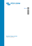
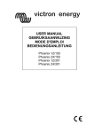
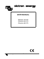
victron energy
USER MANUAL
Phoenix 12/175
Phoenix 24/175
Phoenix 48/175
victron energy
Manual
1
Copyrights © 1999, 2000 Victron Energy B.V.
All Rights Reserved
This publication or part thereoff, may not reproduced in any form by any
method, for any purpose.
VICTRON ENERGY B.V. MAKES NO WARRANTY, EITHER
EXPRESSED OR IMPLIED, INCLUDING BUT NOT LIMITED TO ANY
IMPLIED WARRANTIES OF MERCHANTABILITY OR FITNESS FOR
A PARTICULAR PURPOSE, REGARDING THESE VICTRON ENERGY
PRODUCTS AND MAKES SUCH VICTRON ENERGY PRODUCTS
AVAILABLE SOLELY ON AN “AS-IS” BASIS.
IN NO EVENT SHALL VICTRON ENERGY B.V. BE LIABLE TO
ANYONE FOR SPECIAL, COLLATERAL, INCIDENTAL, OR
CONSEQUENTIAL DAMAGES IN CONNECTION WITH OR ARISING
OUT OF PURCHASE OR USE OF THESE VICTRON ENERGY
PRODUCTS. THE SOLE AND EXCLUSIVE LIABILITY TO VICTRON
ENERGY B.V., REGARDLESS OF THE FORM OF ACTION, SHALL
NOT EXCEED THE PURCHASE PRICE OF THE VICTRON ENERGY
PRODUCTS DESCRIBED HERE IN.
For conditions of use and permission to use this manual for publication in other
than the Dutch, English, French or German language, contact Victron Energy B.V.
Victron Energy B.V. reserves the right to revise and improve its products as it
sees fit. This publication describes the state of this product at the time of its
publication and may not reflect the product at all times in the future.
2
manual
victron energy
INTRODUCTION
Victron Energy has established an international reputation as a leading designer
and manufacturer of energy systems. Our R&D department is the driving force
behind this reputation. It is continually seeking new ways of incorporating the
latest technology in our products. Each step forward results in value-added
technical and economical features.
Our proven philosophy has resulted in a full range of state-of-the-art equipment for
the supply of electrical power. All our equipment meets the most stringent
requirements.
Victron Energy energy systems provide you with high quality AC supplies at
places where there are no permanent sources of mains power.
An automatic stand-alone power system can be created with a configuration
comprising of a Victron Energy inverter, battery charger and last but not least,
batteries with sufficient capacity.
Our equipment is suitable for countless situations in the field, on ships or other
places where a mains supply is indispensable.
Victron Energy has the ideal power source for all kinds of electrical appliances
used for household, technical and industrial purposes, including instruments
susceptible to interference. All of these applications require a high quality power
supply in order to function properly.
Victron Energy Phoenix sinewave inverter
This manual contains instructions for installing the Phoenix 12/175,
Phoenix 24/175 and Phoenix 48/175 sinewave inverters. It describes the
functionality and operation of the Phoenix inverter, including its protective devices
and other technical features.
Note: where the abbreviation ‘Ph’ is used please read ‘Phoenix’ instead.
victron energy
Manual
3
CONTENTS
INTRODUCTION ............................................................3
1. PRECAUTION STATEMENTS ....................................5
2. INSTALLATION ..........................................................6
2.1
2.2
2.3
Location of the inverter
Connection to the battery
General precautions when working with batteries
6
6
8
3. INVERTER OPERATION DETAILS .............................9
3.1
3.2
3.3
Connecting the load
The multi function on/off/economy switch
The economy mode
9
9
10
4. TROUBLESHOOTING..............................................11
4.1
4.2
4.3
The flash sequence table
The indicator modes
Troubleshooting guidelines
11
12
12
5. TECHNICAL DATA...................................................15
5.1
5.2
Phoenix 12/175, 24/175 and 48/175
Global enclosure dimensions
15
16
6. BATTERY CAPACITY...............................................17
6.1
4
Calculation of the minimum required battery capacity
manual
17
victron energy
1.
PRECAUTION STATEMENTS
WARNING
This unit produces high voltages during
operation. Do not open the inverter. Use
the enclosed IEC320 connector to
connect the load.
Do not connect any other AC
generators, like the public grid, to the
inverter. Immediate inverter destruction
will occur.
Apply correct polarity of the battery
wires to the inverter (Red to '+' and
Black to '-'). Reverse polarity
connection will blow an internal fuse so
that the inverter has to be returned for
service.
CAUTION
Opening the inverter, making changes /
modifications to the inverter and
improper installation of the inverter,
will directly void the warranty and
manufacturer's responsibility.
Do not obstruct the airflow around the
inverter. Leave at least 10 cm clearance
around the inverter. Do not place items
on or over the inverter and do not
expose the inverter to high temperature
environments. Ambient temperature
should be between 0 °C and 40 °C
(humidity <95% non condensing). Note
that in some extreme situations the
inverter's case temperature can exceed
70 °C.
Avoid any contact with water on the
inverter. Do not expose the inverter to
rain or moisture.
Do not expose the inverter to dusty
environments.
Never use the inverter at locations
where there is gas or explosion danger.
Like for example directly on top of
batteries.
The inverter's case is directly connected
to the outlet earth terminal. The DC
input wires are not directly connected to
the inverter's case.
If the inverter jumped into an error
mode due to an overload or short
circuit, it automatically restarts after
about 18 seconds. In case of an high
temperature error, automatic restart will
occur after the inverter has cooled down
to an acceptable temperature. Never
service the AC connections when the
inverter is still running in an error mode
or when the inverter is still connected
with a DC supply/battery/battery
charger.
For optimum safety we recommend to
install a GFI (Ground Fault Interruptor)
on the inverter output.
victron energy
Follow the installation guideline of
chapter 2 when installing this inverter.
Do not install directly above the
batteries, sulphur fumes from the
batteries will damage (corrode) the
electronic components.
Manual
5
2.
INSTALLATION
2.1
Location of the inverter
1 Ceiling mounting
(inverted).
2 Base mounting.
3 Vertical wall mounting,
fan at bottom.
4 Vertical wall mounting,
fan on top.
5 Horizontal wall mounting.
2.2
OK
OK
OK (beware of small objects falling through
the ventilation openings on top).
Not recommended
OK
Connection to the battery
The Ph 12/175 is equipped with two 4mm² wires, and the Ph 24/175 and
Ph 48/175 are equipped with two 2.5mm² wires with a length of 1.25 meters. If it
is unavoidable to extend these wires, use a wire gauge of at least 1.5 times larger
than the ones supplied with the inverter. Maximum recommended battery wire
length is approx. 3 meters.
Please follow the step by step installation guideline below. Make sure you are
aware of your local electrical regulations when installing this inverter.
1) Unpack the inverter and check for any physical damage. If the unit has any
physical damage inform your dealer within 3 days after receival. Installing a
damaged unit is not advisable.
2) Check the inverter's top and bottom stickers to confirm if the input and
output voltages are according to your requirements. For example, connecting
a 12V unit to a 24V or 48V battery will immediately destroy the inverter.
6
manual
victron energy
3) The inverter must be placed on a flat surface and can be mounted in the
position as mentioned in section 2.1. The environment in which the inverter
will be installed, must meet the Precaution statements mentioned on chapter
1. The inverter can be mounted with four (Ø 4.5mm max) screws using the
outside U-holes.
4) Battery connection. Before you connect the battery make sure the AC outlet
is safely connected to the load (TV, VCR, radio etc.), or that nothing at all is
connected to the output. In any case make sure that no loose wires are
connected to the inverter's AC output in some way. Note that the inverter
imme diately starts after battery connection!
For 12V systems connect the inverter as follows:
TV,
VCR,
Radio,
etc.
Red
-
Black
To :
12V
+
Battery fuse
(40A)
12V system
Minimum battery capacity should be 50Ah. Make sure you connect the RED
wire to the positive (+) terminal of the battery and the BLACK wire to the
negative (-) terminal.
For 24V systems connect the inverter as follows:
+
12V
-
Red
12V
+
TV,
VCR,
Radio,
etc.
-
Black
To :
Battery fuse
(20A)
24V system
Minimum battery capacity should be 30Ah. Make sure you connect the RED
wire to the positive (+) terminal of the battery and the BLACK wire to the
negative (-) terminal.
For 48V systems connect the inverter as follows:
Black
TV,
VCR,
Radio,
etc.
Red
48V system
victron energy
+
-
To :
Battery fuse
(10A)
Manual
7
Minimum battery capacity should be 20Ah. Make sure you connect the RED
wire to the positive (+) terminal of the battery and the BLACK wire to the
negative (-) terminal.
When you want to attach a 12V universal car plug to the Phoenix12/175 battery
wires make sure that you use the correct polarity. Usually the plug's tip is
positive (+) and the sleeve is negative (-), but this still has to be checked before
connecting it.
It is not advisable to extend the battery wires. Extending these wires may cause
additional losses and/or inverter malfunctioning. If it is unavoidable to extend
these wires, use a wire gauge of at least 1.5 times larger than the standard wire
gauge. Maximum recommended battery wire length is approx. 3 meters.
When the battery is connected to the inverter, the output voltage will be present
on the AC outlet and the red indicator light is on.
2.3
1.
2.
3.
4.
5.
8
General precautions when working with batteries
Working in vicinity of a lead acid battery is dangerous. Batteries can
generate explosive gases during operation. Never smoke or allow a spark or
flame in the vicinity of a battery. Provide sufficient ventilation around the
battery.
Wear eye and clothing protection. Avoid touching eyes while working near
batteries. Wash your hands when done.
If battery acid contacts skin or clothing, wash immediately with soap and
water. If acid enters eye, immediately flood eye with running cold water for
at least 15 minutes and get medical attention immediately.
Be careful when using metal tools in vicinity of batteries. Dropping a metal
tool onto a battery might cause a short-circuited battery and, possibly an
explosion.
Remove personal metal items such as rings, bracelets, necklaces, and
watches when working with a battery. A battery can produce a short-circuit
current high enough to melt a ring or the like to metal, causing severe burns.
manual
victron energy
3.
INVERTER OPERATION DETAILS
3.1
Connecting the load
Before you connect your appliance(s) to the inverter output, always check if the
total power consumption does not exceed 175W. The Phoenix 175W inverters
are able to supply more than 175W for a limited amount of time, with a
maximum peak power of approx. 400W. Some equipment like compressors or
pumps are needing much more power at start-up than Pnom. Using equipment
with a bad power factor (or cos ϕ), like most Personal Computers, reduces the
inverters maximum output power somewhat.
At higher ambient temperatures (>25 °C) the overload capacity of the inverter is
reducing.
Never connect the inverter's output to the AC distribution grid, like your
household AC wall outlet. This will damage the inverter.
3.2
The multi function on/off/economy switch
The Phoenix inverters are equipped with a multi function on/off/economy
switch indicated by the symbol . The main function of this switch is to
activate or deactivate the inverter. When the inverter is activated, the red
indicator LED is on. When you are not using the inverter, it is advisable to
deactivate it in order to save energy from your batteries.
These inverters are equiped with a “ stand-by” switch instead of an on/off
switch, which disconnect the supply voltage to the control circuit. The internal
micro-processor goes into a “sleepmode” when the switch is pressed. This means
that there will allways flow a small current to the inverter when it is switched
“off”.
It is advisable to disconnect the inverter from it’s dc-supply when it is switched
off for a longer time.
The on/off/economy switch can also be used to set the inverter in the so-called
“economy” mode. To activate this mode make sure the inverter and the AC load
are turned off. Then press the on/off/economy switch for 3 seconds until the red
indicator LED starts flashing.
When you want to go back to a normal operating mode, just deactivate and
activate the inverter again by pushing the on/off/economy switch twice. For
further details about the economy mode read chapter 3.3.
victron energy
Manual
9
3.3
The economy mode
To save battery energy when the inverter is running without any load, the
Phoenix 175W inverters are equipped with an economy mode. By activating this
mode, the inverter will generate a test pulse once per second to see if there's a
load connected or not. Between these testpulses the inverter is sleeping, which
drastically reduces it's own power consumption.
When a load is detected (for example by turning on your TV) the inverter will
automatically jump to a normal mode and will supply continuous power to the
load. If you turn off or disconnect the load again, the inverter will jump back to
economy mode after about four seconds (red indicator LED is flashing).
For correct operation of the economy mode make sure the load to be detected is
at least 15W. Smaller loads (<10W at 12V and <15W at 24V or 48V) cannot be
detected so that normal mode is advised.
10
manual
victron energy
4.
TROUBLESHOOTING
4.1
The flash sequence table
Your Phoenix inverter is equipped with a self-diagnosis system, to inform you
about the cause of inverter shut down. To make this visible the red error/power
LED on the front panel of the inverter, can flash in four different sequences. The
duration, or time period, of this sequence is about 1 second. During this time
period, the red LED can flash four times in a row at most. The number of flashes
in this time period indicates the cause of inverter shut down.
In the table below, you can find out what kind of flashing sequence belongs to
which error.
Red LED conditions:
=LED flashing
=LED ON
=LED OFF
Time period
ERROR/ALARM TYPE
Battery voltage too low or too high
( One flash per second )
Overloaded or shorted output
( Two flashes per second )
Inverter temperature too high. Cooling
down ( Three flashes per second )
Inverter in economy mode
( Flashes continuously )
All Phoenix 175W models:
ON, inverter in normal operation
All Phoenix 175W models:
OFF, inverter in standby mode
victron energy
Manual
11
4.2
The indicator modes
To get optimal feedback from your inverter, the red indicator LED has six
different modes of operation:
Off: Inverter is turned off, no AC present on the output.
On: Inverter is activated, 230V (or 117V) AC is present on the output.
One flash per second: (battery error) Inverter turned off due to a too low or too
high battery voltage. No AC present on the output. Inverter restarts automatically
when the battery voltage reaches a normal level.
Two flashes per second: (overload error) Inverter turned off due to an overload
or short circuit on the output. No AC present on the output. Inverter tries to
restart after approx. 18 seconds!
Three flashes per second: (high temperature error) Inverter turned off due to a
too high temperature of the unit. No AC present on the output. Inverter
automatically restarts after it is cooled down sufficiently.
Continuous flashing: (economy mode) Inverter operates in economy mode and is
seeking for a load by generating a test pulse every second. AC periodically
present on the output.
Do not service the AC output when the inverter operating in any mode
(normal, error or economy)! AC lines may only be serviced when the
battery is fully disconnected from the inverter!
4.3
Troubleshooting guidelines
PROBLEM : Inverter is not working (red indicator LED OFF)
Possible cause :
Remedy :
Poor contact between the
inverter’s battery wires and the
battery terminals.
Blown inverter fuse.
Clean battery terminals or inverter wire
contacts. Tighten battery terminal screws.
Very poor battery condition.
12
The Ph 12/175, Ph 24/175 and Ph 48/175
has to be returned for service.
Replace battery.
manual
victron energy
PROBLEM : ‘Battery voltage too low or too high’ error keeps on
appearing
Possible cause :
Remedy :
Poor battery condition.
Poor connection or inadequate
wiring between battery and
inverter, resulting in too much
voltage drop.
Replace battery or charge it first.
When extending the battery wires of the
inverter make sure you use the correct wire
gauge (≥ 1.5 times larger than the fixed
battery wires). It is not advisable to extend
the battery wires to more than 3 meters.
Check your electrical system or consult an
electrical engineer to check it for you.
General failure in your electrical
system (in case of no direct
battery connection).
PROBLEM : ‘Overloaded or shorted output’ error keeps on appearing
Possible cause :
Inverter is overloaded.
Connected equipment features a
bad power factor (cos ϕ at
sinusoidal currents).
Connected equipment causes a
short circuit at the inverter’s
output.
victron energy
Remedy :
Make sure that the total power rating of the
connected equipment is lower than the
nominal inverter power rating.
Reduce the required power consumption of
the load. Please note that, for example, a
computer load features a bad power factor,
which causes a reduction of the maximum
output power of the inverter by approx.
20%.
Make sure that the connected equipment is
not broken or malfunctioning. Check if the
AC power cord between the inverter and
the connected equipment is OK. Any
physical damage on the power cord can
produce a short circuit. Be careful in these
situations!
Manual
13
PROBLEM: ‘Inverter temperature too high. Cooling down’ error keeps
on appearing
Possible cause :
Remedy :
Airflow around the inverter is
obstructed.
Make sure there is at least 10 centimetres of
clearance around the inverter. Remove any
items placed on or over the inverter. Keep
the inverter away from direct sunlight or
heat producing equipment.
Too high ambient temperature.
Move the inverter to a cooler place or
provide additional cooling by an external
fan.
Note: Don’t turn-off the inverter when it’s operating in an ‘Inverter temperature
too high. Cooling down’ error. The inverter needs this error time to cool down.
If none of the above remedies helps to solve the problem you encounter, contact
your local Victron Energy distributor for further help and/or possible repair of
your inverter. Do not open the inverter yourself, there are dangerous high
voltages present inside. Opening the inverter will directly void your 12 months
warranty period.
14
manual
victron energy
5.
TECHNICAL DATA
5.1
Phoenix 12/175, 24/175 and 48/175
TECHNICAL DATA
Ph 12/175
Ph 24/175
Ph 48/175
Output power1) :
175W
175W
175W
P nom @ Ta=40°C
P30
200W
200W
200W
P startup
350W
400W
400W
Output voltage
230Vac ± 1% [or 117Vac ± 2% ]
Output frequency
50Hz ± 0.05% [or 60Hz ± 0.05%]
Output waveform
True sinewave
Total harmonic distortion
Maximum 5% 3)
0.6 - 1
Admissible cos ϕ of load
Input voltage :
Nominal
12Vdc
24Vdc
48Vdc
Range
10.52) - 15.5Vdc
212) - 31Vdc
412) – 59.5Vdc
Maximum efficiency
90%
91%
93%
No load power
< 2.5W
< 3W
< 4W
consumption [economy]
[0.5W]
[0.8W]
[1.2W]
Operating temperature
0 .. 40 °C
range (ambient)
Protections against
Short circuit, overload, high temperature and low battery
voltage
Indications (through different
red indicator LED conditions)
economy threshold
DC input connection
AC output connection
Enclosure body size
(l x h x w)
Protection class
Total weight
The inverter complies
with the following
standards :
Power on, economy mode, short circuit/overload, high
temperature and high/low battery voltage
Pout = 10W
Pout = 15W
Pout = 15W
Two wires, length 1.25 meters, ∅ 2.5mm² (12V= ∅ 4 mm²)
IEC-320 AC outlet
187 x 71 x 110 [without mounting brackets]
IP20
2.1 kg
2.1 kg
2.3 kg
EN50081-1 Generic Emissions Standard
EN50082-1 Generic Immunity Standard
EN60950 Safety Standard
EN60742 Transformer Standard
Note: the given specifications are subject to change without notice
1
) Measured with resistive load
) Undervoltage limit is dynamic. This limit decreases with increasing load to
compensate the voltage drop across cables and connections.
3
) Measured with nominal load Ta=25°C and by nominal input and outputvoltage.
2
victron energy
Manual
15
TOPVIEW
FRONT/
BACK
VIEW
73,0 mm
210,0 mm
16
70,0 mm
MO UNTIN G SC REW
S PA CING WID TH
110,0 m m
D C IN PUT
WIRES
MOU NTIN G SC RE W SPACIN G L ENGTH (4. 5mm diame ter)
manual
ENERGY
VIC T RON
69,0 mm
Fi le : Ph175 DIMENSIONS
Vic tron Energy BV
De Paal 3 5
1351 JG Almere -Haven
The Netherlands
Scale : na
Notes :
Format : na
Rev : 01 Date : 11-04-2001
Dr awn by : K. M eyer
Projec t : Phoenix 175W DC TO AC SINE WAVE INV ER TERS
Title : GLOBAL ENCLOSURE D IM ENSION S
PROT ECTION C LASS : IP20
Phoenix 12/175 : 2.1 kg
Phoenix 24/175 : 2.1 kg
Phoenix 48/175 : 2.3 kg
INVERTER WEIGHT :
269,0 m m
TOTAL LENGTH INCLUD ING IEC320 PLUG AND
N EEDED SPACE FOR DC INPU T W IRES
SIDEVIEW
5.2
Global enclosure dimensions
victron energy
201,0 mm
6.
BATTERY CAPACITY
6.1
Calculation of the minimum required battery capacity
If the power ratings of the equipment to be powered by the Phoenix inverter and
the duration that the inverter is expected to power the equipment are known, the
minimum battery capacity can be calculated.
Make a list of all equipment to be powered by the Phoenix inverter and sum up
each single power consumption multiplied by the duration of time in hours, during
which power will be consumed (Watt-hours). Add the internal loss of the Phoenix
inverter.
The calculation on the internal loss is a two step process. First we calculate the loss
when the inverter is supplying power to a load. The efficiency of the inverter in
this state is 85%, adding roughly 15% to the power consumption. When the
inverter is not supplying power to a load, power consumption is approximately
4.5 W.
Determine the number of Ah by dividing the power consumption by the nominal
battery voltage (for example 24 Vdc). The result is the total battery
capacity-consumption in Ah's. Multiply this value with a safety factor of 1.7 and
the result is the recommended minimum battery capacity.
victron energy
Manual
17
Stock number:
Dealer:
Victron Energy B.V.
The Netherlands
18
General phone:
Customer support desk:
General and Service fax:
Sales fax:
+31 - (0)36 - 535 97 00
+31 - (0)36 - 535 97 77
+31 - (0)36 - 531 16 66
+31 - (0)36 - 535 97 40
E-mail:
Internet site:
[email protected]
http://www.victronenergy.com
Article Number :
Doc. no.
Version
Date
ISM010032000
ISM010032000-*-REV01.doc
01
21-06-2001
manual
victron energy