1
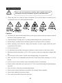
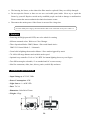
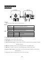
User Guide
Please read the instruction carefully before using
Contents
1. Safety Instructions............................................................................................................................2
2. Features ............................................................................................................................................3
3. Technical Specifications...................................................................................................................3
4. How To Set The Unit .......................................................................................................................4
4.1 Control Panel..............................................................................................................................4
4.2 Main Function ............................................................................................................................5
5. How To Set The Unit .....................................................................................................................10
5.1 Master/Slave Built In Preprogrammed Function .....................................................................10
5.2 Easy Controller ........................................................................................................................ 11
5.3 DMX Controller....................................................................................................................... 11
5.4 DMX 512 Configuration..........................................................................................................12
5.5 DMX512 Connection...............................................................................................................13
6. Troubleshooting .............................................................................................................................14
7. Cleaning And Maintenance............................................................................................................15
1A
1. Safety Instructions
Please read the instructions carefully which includes important
information about the installation, operation and maintenance.
y
Please keep this User Guide for future consultation. If you sell the fixture to another user, be
sure that they also receive this instruction booklet.
Cautions:
y All fixtures are intact from the manufacturer, please operate follow up the user manual, artificial
fault are not under guarantee repair.
y Unpack and check carefully there is no transportation damage before using the fixture.
y Be sure that no ventilation slots are blocked, otherwise the fixture will be overheated.
y Before operating, ensure that the voltage and frequency of power supply match the power
requirements of the fixture.
y Use in a dry location.
y It’s important to ground the yellow/green conductor to earth in order to avoid electric shock.
y Maximum ambient temperature is 40℃. Don’t operate it where the temperature is higher than
this.
y First run, there will be smoke or smells, and all disappearing a few minutes later.
y Make sure there are no flammable materials close to the fixture while operating, as it is fire
hazard.
y Look over power wires carefully, replace immediately if there is any damage.
y Fixture surface temperature may reach up to 65℃. Don’t touch the housing bare-hand during its
operation.
y Never run on for a long time lest shortening lifespan.
y Do not operate in dirty and dusty environment, also cleaning fixtures regularly.
y Do not allow children to operate the fixture.
y Never turn on and off the fixture time after time.
2A
y The housing, the lenses, or the ultraviolet filter must be replaced if they are visibly damaged.
y Do not open the fixture as there are no user serviceable parts inside. Never try to repair the
fixture by yourself. Repairs carried out by unskilled people can lead to damage or malfunction.
Please contact the nearest authorized technical assistance center.
y Disconnect the mains power if the fixture is not used for a long time.
For 230V 50Hz power supply, maximum fixtures that can be connected on one power cable is 7.
2. Features
• Featuring 60W high powerful LED, one color wheel for creating
different saturated colors. Work as a Color Changer.
• Three Operation Modes: DMX, Master / Slave and Sound Active
DMX 512 Control Mode: 3 / 8 channels
• Great built-in lighting shows under Master / Slave mode triggered by music
• 70~100% full range dimmer and variable strobe speed
• Optional easy controller CA-8 or CA-9 RTX for instant lighting shows at your fingers
• Two different angles selectable, 9° as standard and 14° as an accessory
• Ideal for restaurants, clubs, bars, discos, parties, mobile Djs and more
3. Technical Specifications
• Input Voltage:AC 230V, 50Hz
• Power Consumption: 95W
• Light Source: 1 × 60W LED
• Fuse: T 6.3A
• Dimension: 268×266×233mm
• Weight: 4.2kgs
3A
4. How To Set The Unit
4.1 Control Panel
1. Display
Show the various menus and the selected functions.
Button
2.MENU
To select the programming functions
3.DOWN
4.UP
5.ENTER
To go backward in the selected functions
To go forward in the selected functions
To confirm the selected functions
6.DMX
7.MASTER
8.SOUND
9.SLAVE
On
On
Flashing
On
LED
DMX input present
Master Mode
Sound activation
Slave Mode
10. Power in: Power connection to power source.
11. Safety hook: Used to connect safety cable to.
12. Microphone: Receive music for the sound active.
13. Only for wireless receiver: Connect with CA-9 RTX to control the unit for Stand by, Function
and Mode function.
14. DMX in: For DMX 512 link, use 3-pin XLR plug cable to input DMX signal.
15. DMX out: For DMX 512 link, use 3-pin XLR plug cable to link the next fixture.
16.Only for remote control: Connect with CA-8 to control the unit for Stand by, Function and
Mode function.
17. Power out: Connect to supply mains power for the next fixture.
4A
4.2 Main Function
To select any of the given functions, press the MENU button up to when the required one is
showing on the display. Select the function by the ENTER button and the display will blink. Use
the DOWN and UP button to change the mode. Once the required mode has been selected, press
the ENTER button to setup or it will automatically return to the main functions without any change
after idling 8 seconds. To go back to the functions without any change press the MENU button. The
main functions are showing below:
5A
6A
DMX 512 Address Setting
Select the
, press the ENTER button and the display will blink. Use the DOWN and UP
button to change the DMX512 address. Once the address has been selected, press the ENTER
button to setup or automatically return to the main functions without any change after 8 seconds. To
go back to the functions without any change press the MENU button again.
Channel Mode
, press the ENTER button and the display will blink. Use the DOWN and UP
Select the
button to select the
(3 channel) or
(8 channel) mode. Once the channel mode has
been selected, press the ENTER button to setup, to go back to the functions without any change
press the MENU button again. Hold and press the MENU button about one second or wait for one
minute to exit the menu mode.
Slave Mode
Select the
, press the ENTER button and the display will blink. Use the DOWN and UP
button to select the
(normal) or
(2 light show) mode. Once the mode has been
selected, press the ENTER button to setup, to go back to the functions without any change press
the MENU button again. Hold and press the MENU button about one second or wait for one
minute to exit the menu mode.
Split Color Mode
Select the
, press the ENTER button and the display will blink. Use the DOWN and UP
button to select the
(Split color mode) or
(normal). Once the mode has been selected,
press the ENTER button to setup, to go back to the functions without any change press the MENU
button again. Hold and press the MENU button about one second or wait for one minute to exit the
menu mode.
7A
Dimmer Calibrate
Select the
, press the ENTER button and the display will blink. Use the DOWN and UP
button to calibrate the dimmer for a maximum output from
max. output) to
(limited to 70% of the really
(maximum output is not limited). Once the mode has been selected, press
the ENTER button to setup, to go back to the functions without any change press the MENU
button again. Hold and press the MENU button about one second or wait for one minute to exit the
menu mode.
Sound Mode
Select the
is showing on the display. Pressing the ENTER button and the display will blink.
Use the DOWN and UP button to select the
(sound on) or
(sound off) mode. Once
the mode has been selected, press the ENTER button to setup or automatically return to the main
functions without any change after 8 seconds. To go back to the functions without any change press
the MENU button again.
Sound Sense
Select the
, press the ENTER button and the display will blink. Use the DOWN and UP
and
button to adjust the sound sensitivity between
. Once selected, press the ENTER
button to setup, to go back to the functions without any change press the MENU button again. Hold
and press the MENU button about one second or wait for one minute to exit the menu mode.
Blackout Mode
Select the
, press the ENTER button and the display will blink. Use the DOWN and UP
button to select the
(yes blackout) or
(no blackout) mode. Once selected, press the
ENTER button to setup or automatically return to the main functions without any change after 8
seconds. To go back to the functions without any change press the MENU button again.
8A
LED Display
Select the
, press the ENTER button and the display will blink. Use the DOWN and UP
button to select the
(LED on) or
(LED off). Once the mode has been selected, press
the ENTER button to setup or automatically return to the main functions without any change after
8 seconds. To go back to the functions without any change press the MENU button again.
Display Inversion
Select the
, press the ENTER button and the display will blink. Use the DOWN and UP
button to select the
(normal) or
(display inversion). Once selected, press the
ENTER button to setup or automatically return to the main functions without any change after 8
seconds. To go back to the functions without any change press the MENU button again.
Auto Test
Select the
, press the ENTER button and the fixture will run the built-in program to test the
fixture. To go back to the functions press the MENU button again.
Temperature Test
Select the
, press the ENTER button and the display will show the temperature of the unit.
To go back to the functions press the MENU button again.
Fixture Hours
Select the
, press the ENTER button and the display will show the number of working hours
of the unit. To go back to the functions press the MENU button again.
Software version
Select the
, press the ENTER button and the display will show the version of software of the
unit. To go back to the functions press the MENU button again. Hold and press the MENU button
about one second or wait for one minute to exit the menu mode.
9A
PRO Defaults
Select the
, press the ENTER button and the display will blink. Use the DOWN and UP
button to select the
(run built-in program to set the fixture to factory settings) or
.
Press the ENTER button to setup, to go back to the functions without any change press the MENU
button again. Hold and press the MENU button about one second or wait for one minute to exit the
menu mode.
Reset
Press the MENU button to show the
on the display. Press the ENTER button and all
channels of the unit will return to their standard position.
5. How To Set The Unit
You can operate the unit in three ways:
1. By master/slave built-in preprogram function
2. By easy controller
3. By universal DMX controller
No need to turn the unit off when you change the DMX address, as new DMX address setting will
be effected at once. Every time you turn the unit on, it will show the
on the display and
move all the motors to their ‘home’ position and you may hear some noises for about 20 seconds.
After that the unit will be ready to receive DMX signal or run the built-in programs.
5.1 Master/Slave Built In Preprogrammed Function
By linking the units in master/slave connection, the first unit will control the other units to give an
automatic, sound activated, synchronized light show. This function is good when you want an
instant show.
2-light show
In
(slave mode),
means the unit works normally and
means 2-light show. In
on the second unit to get contrast movement
order to create a great light show, you can set
to each other, even if you have two units only.
10A
5.2 Easy Controller
The easy remote control is used only in master/slave mode. By connecting to the 1/4” microphone
jack of the first unit, you will find that the remote control on the first unit will control all the other
units functions press the MENU button again.
Stand By
Function
Mode
Blackout the unit
1. Sync. Strobe
2. Async strobe
3. Sound Strobe
Sound (LED OFF)
Select Color
Color (LED On)
5.3 DMX Controller
An universal DMX controller to control the units, you have to set DMX address from 1 to 512
channel so that the units can receive DMX signal.
Press the MENU button up to when the
is showing on the display. Press the ENTER button
and the display will blink. Use the DOWN and UP button to change the DMX512 address. Once
the address has been selected, press and keep the ENTER button pressed up to when the display
stops blinking or storing automatically 8 seconds later. To go back to the functions without any
change press the MENU button again.
If you use please refer to the following diagram to address your DMX512 channel for the first 4
units.
11A
5.4 DMX 512 Configuration
3/8 Channels Mode:
12A
5.5 DMX512 Connection
The DMX 512 is widely used in intelligent lighting control, with a maximum of 512 channels.
1. If you using a controller with 5 pins DMX output, you need to use a 5 to 3 pin adapter-cable.
2. At last unit, the DMX cable has to be terminated with a terminator. Solder a 120 ohm 1/4W
resistor between pin 2(DMX-) and pin 3(DMX+) into a 3-pin XLR-plug and plug it in the
DMX-output of the last unit.
3. Connect the unit together in a `daisy chain` by XLR plug from the output of the unit to the
input of the next unit. The cable can not branched or split to a `Y` cable. DMX 512 is a very
high-speed signal. Inadequate or damaged cables, soldered joints or corroded connectors can
easily distort the signal and shut down the system.
4. The DMX output and input connectors are pass-through to maintain the DMX circuit, when
power is disconnected to the unit.
5. Each lighting unit needs to have an address set to receive the data sent by the controller. The
address number is between 0-511 (usually 0 & 1 are equal to 1).
6. The end of the DMX 512 system should be terminated to reduce signal errors.
7. 3 pin XLR connectors are more popular than 5 pin XLR.
13A
3 pin XLR: Pin 1: GND, Pin 2: Negative signal (-), Pin 3: Positive signal (+)
5 pin XLR: Pin 1: GND, Pin 2: Negative signal (-), Pin 3: Positive signal (+)
6. Troubleshooting
Following are a few common problems that may occur during operation. Here are some
suggestions for easy troubleshooting:
A. The unit does not work, no light and the fan does not work
1. Check the connection of power and main fuse.
2. Measure the mains voltage on the main connector.
3. Check the power on LED.
B. Not responding to DMX controller
1. The DMX LED should be on. If not, check DMX connectors, cables to see if link properly.
2. If the DMX LED is on and no response to the channel, check the address settings and
DMX polarity.
3. If you have intermittent DMX signal problems, check the pins on connectors or on PCB of the
unit or the previous one.
4. Try to use another DMX controller.
5. Check if the DMX cables run near or run alongside to high voltage cables that may cause
damage or interference to DMX interface circuit.
C. Some units don’t respond to the easy controller
1. You may have a break in the DMX cabling. Check the LED for the response of the master/
slave mode signal.
2. Wrong DMX address in the unit. Set the proper address.
D. No response to the sound
1. Make sure the unit does not receive DMX signal.
2. Check microphone to see if it is good by tapping the microphone
14A
E. One of the channels is not working well
1. The stepper motor might be damaged or the cable connected to the PCB is broken.
2. The motor’s drive IC on the PCB might be out of condition
7. Cleaning And Maintenance
The cleaning must be carried out periodically to optimize light output. Cleaning frequency depends
on the environment in which the fixture operates: moist, smoky or particularly dirty surrounding
can cause greater accumulation of dirt on the fixture.
y
Clean with lint-free cloth using normal glass cleaning liquid.
y
Always dry the parts carefully.
y
Clean the surface at least every 30 days.
y
Never use alcohol or solvents.
15A
Declaration of Conformity
We declare that our products (lighting equipments) comply with the following
specification and bears CE mark in accordance with the provision of the
Electromagnetic Compatibility (EMC) Directive 2004/108/EC.
EN55103-1: 2009 ; EN55103-2: 2009;
EN61000-3-2: 2006 + A1:2009 + A2:2009; EN61000-3-3: 2008.
&
Harmonized Standard
EN 60598-1:2008 + All:2009; EN 60598-2-17:1989 + A2:1991;
EN 62471:2008; EN 62493: 2010
Safety of household and similar electrical appliances
Part 1: General requirements
Innovation, Quality, Performance