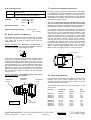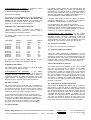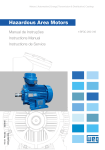
1
INSTRUCTION MANUAL (ATEX / IECEx)
BExBG15D and BExBG10D
Flameproof Xenon Beacons
For use in Flammable Gas and Dust Atmospheres
1)
Introduction
The BExBG15D and BExBG10D are flameproof beacons
which are certified to meet the requirements of the ATEX
directive 94/9/EC and the IECEx scheme. The beacons
produce synchronised visual warning signals and can be
used in hazardous areas where potentially flammable gas
and dust atmospheres may be present. The BExBG15D has
a flash energy of 15 joules and the BExBG10D has a flash
energy of 10 joules. Both beacons can be used in Zone 1 and
Zone 2 areas with gases in groups IIA, IIB and IIC and
Temperature Classifications of T1, T2, T3 and T4. The
beacons can also be used in the temperature classification
T5, if the upper ambient temperature is restricted to +40ºC.
The units can be used in Zone 21 and Zone 22 areas for
combustible dusts and have an IP rating of IP 67 and a
surface temperature rating of T125ºC or T110ºC if the upper
ambient temperature is restricted to +55ºC or T95ºC if the
upper ambient temperature is restricted to +40ºC.
2)
Marking
All units have a rating label, which carries the following
important information:Unit Type No.
BExBG15D or BExBG10D
Input Voltage:
DC Units
AC Units
Codes:
24V or 48V or 12V (10J only)
230V or 115V
Ex d IIC T4 for Ta –50ºC to +70ºC
Ex d IIC T5 for Ta –50ºC to +40ºC
Ex tD A21 IP67 T125ºC based on max. Ta of +70ºC
Certificate No’s
KEMA 00ATEX2006
IECEx KEM 10.0002
Epsilon x:
Equipment Group and
Category:
II 2G/D
EN60079-0:2006 IEC60079-0:2004 (Ed4)
EN60079-1:2007 IEC60079-1:2007 (Ed6)
General Requirements
Flameproof Enclosure ‘d’
EN61241-0:2006 IEC61241-0:2004 (Ed1)
Dust General
Requirements
Dust Enclosures tD
EN61241-1:2004 IEC60079-1:2004 (Ed1)
4) Installation Requirements
The beacons must be installed in accordance with the latest
issues of the relevant parts of the EN60079 standards or the
equivalent IEC standards – Selection, Installation and
maintenance of electrical apparatus for use in potentially
explosive atmospheres (other than mining applications or
explosive processing and manufacture):EN60079-14:2008
IEC60079-14:2007 (Ed4)
Electrical Installations in Hazardous
Areas (other than mines)
EN60079-10:2003
IEC60079-10:2008 (Ed1)
Classification of Hazardous Areas
The installation of the units must also be in accordance with
any local codes that may apply and should only be carried
out by a competent electrical engineer who has the
necessary training.
5) Zones, Gas Group, Category, IP Rating and
Temperature Classification
The BExBG15D and BExBG10D beacons have been certified
Ex d IIC T4 for Ta –50ºC to +70ºC and Ex d IIC T5 for Ta –
50ºC to +40ºC for gas and IP67 T125ºC based on max. Ta of
+70ºC. This means that the units can be installed in
locations with the following conditions:Area Classification Gas:
CE Marking
Notified Body No.
“Warnings”
The beacons have EC Type Examination and IECEx
certificates issued by KEMA and have been approved to the
following standards:-
0518
Zone 1
Zone 2
DO NOT OPEN WHEN AN EXPLOSIVE
GAS OR DUST ATMOSPHERE IS PRESENT
COVER BOLTS CLASS A4-80
USE HEAT RESISTING CABLES AND CABLE GLANDS
(Rated 110ºC) AT AMB. TEMPERATURES OVER 40ºC
90º
Year of Construction/
Serial No.
Explosive gas air mixture likely to occur in
normal operation.
Explosive gas air mixture not likely to occur,
and if it does, it will only exist for a short time.
Gas Groupings:
Group IIA
Group IIB
Group IIC
Propane
Ethylene
Hydrogen and Acetylene
Temperature Classification:
i.e. 10 / 1DB22000001
3) Type Approval Standards
T1
T2
T3
T4
400o C
300o C
200o C
135o C
T5
100o C
Amb. +40ºC
_______________________________________________________________________________________________________________________________
European Safety Systems Ltd. Impress House, Mansell Road, Acton, London W3 7QH
[email protected]
Tel: +44 (0)208 743 8880
www.e-2-s.com
Fax: +44 (0)208 740 4200
Document No. IS 2459-P
Issue E
12-03-10
Sheet 1 of 4
(1)
7) Access to the Flameproof Enclosure
Area Classification Dust:
Zone 21
Zone 22
Explosive dust air mixture likely to occur in
normal operation.
Explosive dust air mixture not likely to occur, and
if it does, it will only exist for a short time.
IP Rating:
IP67
T125ºC Ta < +70ºC
T110ºC Ta < +55ºC
T95ºC Ta < +40ºC
Equipment Category:
Note the four M6 screws are Class A4-80 stainless steel
and only screws of this category can be used on these
beacons. It is therefore important that these screws and their
spring washers are kept in a safe place during installation.
2G/D
Ambient Temperature Range:
In order to connect the electrical supply cables to the beacon
it is necessary to remove the flameproof cover to gain access
to the flameproof chamber. To achieve this remove the four
M6 hexagon socket head screws (see figure 2) and withdraw
the flameproof cover taking extreme care not to damage the
flameproof joints in the process.
-50°C to +70°C
(T5 = +40ºC)
6) Beacon Location and Mounting
The location of the beacons should be made with due regard
to the area over which the warning signal must be visible.
They should only be fixed to services that can carry the
weight of the unit.
SAFETY WARNING: The BExBG15D and BExBG10D 15
and 10 joule beacons must be mounted with their flashdome
in a position between upright and 90º as shown.
On completion of the cable wiring installation the flameproof
joints should be inspected to ensure that they are clean and
that they have not been damaged during installation. Also
check that the earth bonding wire between the two casting
sections is secure and the ‘O’ ring seal is in place. When
replacing the flameproof cover casting ensure that it is square
with the flameproof chamber casting before inserting.
Carefully push the cover in place allowing time for the air to
be expelled. Only after the cover is fully in place should the
four M6 Stainless Steel A4-80 cover bolts and their spring
washer be inserted and tightened down. If the cover jams
while it is being inserted, carefully remove it and try again.
Never use the cover bolts to force the cover into position.
90º
4 off M6 Cover Screws
External Earth
Terminal
The beacons should be securely bolted to a suitable surface
using the 7mm diameter boltholes in the stainless steel U
shaped mounting bracket (see figure 1). The angle can then
be adjusted as required but the mounting restrictions must be
observed (see above). This can be achieved by loosening the
two large bracket screws in the side of the unit, which allow
adjustment in steps of 18°. On completion of the installation
the two large bracket adjustment screws on the side of the
unit must be fully tightened to ensure that the unit cannot
move in service.
SAFETY WARNING: The flashdome guard must not be
removed from the unit at any time.
Flashdome
Guard
Flameproof
Chamber
Flameproof
Cover
Figure 2
8) Power Supply Selection
It is important that a suitable power supply is used to run the
beacons. The power supply selected must have the
necessary capacity to provide the input current to all of the
beacons connected to the system.
The following table shows the input current taken by the
various units:-
Figure 1
S/S Bracket
Unit Type
Nominal I/P
Voltage
Input
Current
Max.
I/P Volts
BExBG15D
BExBG15D
BExBG15D
BExBG15D
24V DC
48V DC
230V AC
115V AC
860mA
480mA
170mA
360mA
30V
58V
253V
126V
BExBG10D
BExBG10D
BExBG10D
BExBG10D
BExBG10D
12V DC
24V DC
48V DC
230V AC
115V AC
1.45A
660mA
340mA
110mA
250mA
15V
30V
58V
253V
126V
_______________________________________________________________________________________________________________________________
European Safety Systems Ltd. Impress House, Mansell Road, Acton, London W3 7QH
[email protected]
Tel: +44 (0)208 743 8880
www.e-2-s.com
Fax: +44 (0)208 740 4200
Document No. IS 2459-P
Issue E
12-03-10
Sheet 2 of 4
(2)
The input current will vary according to the voltage input
level. The current levels shown above are for nominal input
voltage. The 12V, 24V and 48V DC units have a converter
circuit and therefore the input current level will decrease
slightly as the input voltage in increased and will increase
slightly as the input voltage is reduced.
The above table also shows the maximum voltages at which
the beacons can be operated.
9) Cable Selection
When selecting the cable size consideration must be given to
the input current that each unit draws (see table above), the
number of beacons on the line and the length of the cable
runs. The cable size selected must have the necessary
capacity to provide the input current to all of the beacons
connected to the line.
SAFETY WARNING: If the BExBG15D and BExBG10D
beacons are used at high ambient temperatures, i.e. over
+40ºC, then the cable entry temperature may exceed +70ºC
and therefore suitable heat resisting cables must be used,
with a rated service temperature of at least 110ºC.
11) Cable Glands
The BExBG15D and BExBG10D beacons have dual cable
gland entries which have an M20 x1.5 entry thread as
standard. Only cable glands approved for Ex ‘d’ applications
can be used, which must be suitable for the type of cable
being used and also meet the requirements of the Ex ‘d’
flameproof installation standard EN60079-14:2008 /
IEC60079-14:2007.
When only one cable entry is used the other one must be
closed with an Ex ‘d’ flameproof blanking plug, which must be
suitably approved for the installation requirements.
For combustible dust applications, the cable entry device and
blanking elements shall be in type of explosion protection
increased safety "e" or flameproof enclosure "d" and shall
have an IP 6X rating according to EN60529:1992.
SAFETY WARNING: If the BExBG15D and BExBG10D
beacons are used at high ambient temperatures, i.e. over
+40ºC, then the cable entry temperature may exceed +70ºC
and therefore suitable heat resisting cable glands must be
used, with a rated service temperature of at least 110ºC.
12) Cable Connections
10) Earthing
Both AC and DC beacon units must be connected to a good
quality earth. The units are provided with internal and
external earthing terminals which are both located on the
terminal chamber section of the unit (see figures 2 and 3).
When using the internal earth terminal ensure that the
stainless steel M4 flat washer is between the incoming earth
wire and the enclosure.
When using the external earth terminal a cable crimp lug
must be used. The cable lug should be located between the
two M5 stainless steel flat washers. The M5 stainless steel
spring washer must be fixed between the outer flat washer
and the M5 stainless steel nut to ensure that the cable lug is
secured against loosening and twisting.
The cable connections are made into the terminal blocks on
the electronic pcb assembly located in the flameproof
enclosure. See section 7 of this manual for access to the
flameproof enclosure. A four-way terminal block is provided
on both AC and DC beacons. Therefore there are two live
terminals and two neutral terminals for the input and output
wiring on AC units. On the DC units there are two +ve
terminals and two -ve terminals for the input and output
wiring.
BExBG15D and BExBG10DD 15 and 10 Joule Beacons
Flip / Flop
Terminal
Header
Supply
Terminals
The internal earth bonding wire ensures that a good quality
earth is maintained between the flameproof chamber casting
and the flameproof cover casting.
BExBG15D and BExBG10D Beacon Cover Internal
View
Figure 4
Internal Bonding
Wire Terminal
2 off M20
Cable Entries
Internal Earth Terminal
Wires having a cross sectional area of up to 2.5mm² can be
connected to each terminal way. If an input and output wire is
required a 2.5mm² wire can be connected to each terminal
way. When connecting wires to the terminals great care
should be taken to dress the wires so that when the cover is
inserted into the chamber the wires do not exert excess
pressure on the terminal blocks. This is particularly important
when using cables with large cross sectional areas such as
2.5mm².
Figure 3
_______________________________________________________________________________________________________________________________
European Safety Systems Ltd. Impress House, Mansell Road, Acton, London W3 7QH
[email protected]
Tel: +44 (0)208 743 8880
www.e-2-s.com
Fax: +44 (0)208 740 4200
Document No. IS 2459-P
Issue E
12-03-10
Sheet 3 of 4
(3)
13) Synchronised Operation
All BExBG15D and BExBG10D beacons that are connected
to the same supply line will have a synchronised flash rate at
one flash every second. To ensure that the units will be
synchronised check that the pin header is not fitted, i.e. the
two header pins are not shorted together (see Figure 4).
14) Flip-Flop Operation
Two beacons can be mounted close to each other to form a
flip-flop operation, where the beacons will flash alternately.
To achieve this mode of operation, fit a pin header to the flipflop header pins on the electronics board, i.e. the two header
pins are shorted together, (see figure 4) on one of the two
beacons. The first flash on the beacon that has the header
fitted will be delayed by ½ second. The two beacons will then
flash alternately every ½ a second.
15) End of Line Monitoring (DC Units)
On the BExBG15D and BExBG10D DC beacons, dc reverse
line monitoring can be used if required. All DC beacons have
a blocking diode fitted in their supply input lines. An end of
line monitoring diode or an end of line monitoring resistor can
be connected across the +ve and –ve terminals. If an end of
line resistor is used it must have a minimum resistance value
of 3k3 ohms and a minimum wattage of 0.5 watts or a
minimum resistance value of 500 ohms and a minimum
wattage of 2 watts.
_______________________________________________________________________________________________________________________________
European Safety Systems Ltd. Impress House, Mansell Road, Acton, London W3 7QH
[email protected]
Tel: +44 (0)208 743 8880
www.e-2-s.com
Fax: +44 (0)208 740 4200
Document No. IS 2459-P
Issue E
12-03-10
Sheet 4 of 4
(4)
INSTRUCTION MANUAL (ATEX / IECEx) (GBR)
BExBG15D and BExBG10D
Flameproof Xenon Beacons
For use in Flammable Gas and Dust Atmospheres
2) Marking
All units have a rating label, which carries the following
important information:Unit Type No.
BExBG15D or BExBG10D
Input Voltage:
DC Units
AC Units
Codes:
Propane
Ethylene
Hydrogen and Acetylene
Temperature Classification:
KEMA 00ATEX2006
IECEx KEM 10.0002
Epsilon x:
Equipment Group and
Category:
II 2G/D
T1
T2
T3
T4
400o C
300o C
200o C
135o C
T5
100o C
Amb. +40ºC
Area Classification Dust:
Zone 21
CE Marking
Notified Body No.
“Warnings”
Group IIA
Group IIB
Group IIC
24V or 48V or 12V (10J only)
230V or 115V
Ex d IIC T4 for Ta –50ºC to +70ºC
Ex d IIC T5 for Ta –50ºC to +40ºC
Ex tD A21 IP67 T125ºC based on max. Ta of +70ºC
Certificate No’s
Gas Groupings:
0518
Zone 22
DO NOT OPEN WHEN AN EXPLOSIVE
GAS OR DUST ATMOSPHERE IS PRESENT
IP Rating
Explosive dust air mixture likely to occur in
normal operation.
Explosive dust air mixture not likely to occur,
and if it does, it will only exist for a short time.
IP67
COVER BOLTS CLASS A4-80
USE HEAT RESISTING CABLES AND CABLE GLANDS
(Rated 110ºC) AT AMB. TEMPERATURES OVER 40ºC
Equipment Category:
T125ºC
T110ºC
T95ºC
Ta < +70ºC
Ta < +55ºC
Ta < +40ºC
2G/D
Ambient Temperature Range:
90º
-50°C to +70°C
(T5 = +40ºC)
4) Installation Requirements
6) Beacon Location and Mounting
Beacons must be installed in accordance with the following or
equivalent standards.
See drawing A
EN60079-14:2008
IEC60079-14:2007 (Ed4)
EN60079-10:2003
Electrical Installations in Hazardous
Areas (other than mines)
Classification of Hazardous Areas
SAFETY WARNING: The BExBG15D and BExBG10D 15
and 10 joule beacons must be mounted with their flashdome
in a position between upright and 90º as shown.
IEC60079-10:2008 (Ed1)
90º
Installation should only be carried by competent personnel
and any local codes of practice applied.
5) Zones, Gas Group, Category and Temperature
Classification
SAFETY WARNING: The flashdome guard must not be
removed from the unit at any time.
Area Classification:
Zone 1
Zone 2
Explosive gas air mixture likely to occur in
normal operation.
Explosive gas air mixture not likely to occur,
and if it does, it will only exist for a short time.
7) Access to the Flameproof Enclosure
See drawing B
_______________________________________________________________________________________________________________________________
European Safety Systems Ltd. Impress House, Mansell Road, Acton, London W3 7QH
[email protected]
Tel: +44 (0)20 8743 8880
www.e-2-s.com
Fax: +44 (0)20 8740 4200
Document No. BExBG15D and BExBG10D (Gas-Dust) English
Issue E (Four Sheets)
12-03-10
(5)
Note the four M6 screws are Class A4-80 stainless steel
and only screws of this category can be used on these
beacons. It is therefore important that these screws and their
spring washers are kept in a safe place during installation.
standard. Only cable glands approved for Ex ‘d’ applications
can be used, which must be suitable for the type of cable
being used and also meet the requirements of the Ex ‘d’
flameproof installation standard EN60079-14:2008 /
IEC60079-14:2007.
8) Power Supply Selection
When only one cable entry is used the other one must be
closed with an Ex ‘d’ flameproof blanking plug, which must be
suitably approved for the installation requirements.
The system power supply must have the necessary capacity
to provide the input current to all of the beacons connected to
the system.
The following table shows the input current taken by the
various units:Unit Type
Nominal I/P
Voltage
Input
Current
Max.
I/P Volts
BExBG15D
BExBG15D
BExBG15D
BExBG15D
24V DC
48V DC
230V AC
115V AC
860mA
480mA
170mA
360mA
30V
58V
253V
126V
BExBG10D
BExBG10D
BExBG10D
BExBG10D
BExBG10D
12V DC
24V DC
48V DC
230V AC
115V AC
1.45A
660mA
340mA
110mA
250mA
15V
30V
58V
253V
126V
The above table also shows the maximum voltages at which
the beacons can be operated.
9) Cable Selection
Cables must be capable of handling the current drawn from
all of the units on the line.
SAFETY WARNING: If the BExBG15D and BExBG10D
beacons are used at high ambient temperatures, i.e. over
+40ºC, then the cable entry temperature may exceed +70ºC
and therefore suitable heat resisting cables must be used,
with a rated service temperature of at least 110ºC.
10) Earthing
Both AC and DC beacon units must be connected to a good
quality earth. The units are provided with internal and
external earthing terminals which are both located on the
terminal chamber section of the unit (see figures 2 and 3).
When using the internal earth terminal ensure that the
stainless steel M4 flat washer is between the incoming earth
wire and the enclosure.
When using the external earth terminal a cable crimp lug
must be used. The cable lug should be located between the
two M5 stainless steel flat washers. The M5 stainless steel
spring washer must be fixed between the outer flat washer
and the M5 stainless steel nut to ensure that the cable lug is
secured against loosening and twisting.
For combustible dust applications, the cable entry device and
blanking elements shall be in type of explosion protection
increased safety “e” or flameproof enclosure “d” and shall
have an IP 6X rating according to EN60529:1992.
SAFETY WARNING: If the BExBG15D and BExBG10D
beacons are used at high ambient temperatures, i.e. over
+40ºC, then the cable entry temperature may exceed +70ºC
and therefore suitable heat resisting cable glands must be
used, with a rated service temperature of at least 110ºC.
12) Cable Connections
See drawings C and D / wiring diagram E
13) Synchronised Operation
All BExBG15D and BExBG10D beacons that are connected
to the same supply line will have a synchronised flash rate at
one flash every second. To ensure that the units will be
synchronised check that the pin header is not fitted, i.e. the
two header pins are not shorted together (see Figure 4).
14) Flip-Flop Operation
Two beacons can be mounted close to each other to form a
flip-flop operation, where the beacons will flash alternately.
To achieve this mode of operation, fit a pin header to the flipflop header pins on the electronics board, i.e. the two header
pins are shorted together, (see figure 4) on one of the two
beacons. The first flash on the beacon that has the header
fitted will be delayed by ½ second. The two beacons will then
flash alternately every ½ a second.
15) End of Line Monitoring (DC Units)
On the BExBG15D and BExBG10D DC beacons, dc reverse
line monitoring can be used if required. All DC beacons have
a blocking diode fitted in their supply input lines. An end of
line monitoring diode or an end of line monitoring resistor can
be connected across the +ve and –ve terminals. If an end of
line resistor is used it must have a minimum resistance value
of 3k3 ohms and a minimum wattage of 0.5 watts or a
minimum resistance value of 500 ohms and a minimum
wattage of 2 watts.
The internal earth bonding wire ensures that a good quality
earth is maintained between the flameproof chamber casting
and the flameproof cover casting.
11) Cable Glands
The BExBG15D and BExBG10D beacons have dual cable
gland entries which have an M20 x1.5 entry thread as
_______________________________________________________________________________________________________________________________
European Safety Systems Ltd. Impress House, Mansell Road, Acton, London W3 7QH
[email protected]
Tel: +44 (0)20 8743 8880
www.e-2-s.com
Fax: +44 (0)20 8740 4200
Document No. BExBG15D and BExBG10D (Gas-Dust) English
Issue E (Four Sheets) 12-03-10
(6)
Drawing A
Drawing C
L L N N
Lossen screw
to adjust
Loosen screw to adjust.
90º
Tighten screw
to secure
Løsn skruen for at tilpasse.
Schroef losdraaien om af te stellen.
Desserrer la vis pour régler.
Zum Regulieren Schraube lockern.
Allentare la vite per poter effettuare la
regolazione.
Løsne skruen for å justere.
Desaperte o parafuso para ajustar.
Afloje el tornillo para ajustar.
Lossa skruven för att justera.
Tighten screw to secure.
Spænd skruen for at fastgøre.
Schroef aandraaien om vast te zetten.
Serrer la vis pour une fixation sûre.
Zum Sichern Schraube anziehen.
Stringere la vite per il fissaggio.
Stram skruen for å feste.
Aperte o parafuso para fixar.
Apriete el tornillo para asegurar.
Dra åt skruven för att fästa.
BExBG15D and
BExBG10D
AC units
Drawing D
- - + +
Drawing B
BExBG15D and
BExBG10D
DC units
_______________________________________________________________________________________________________________________________
European Safety Systems Ltd. Impress House, Mansell Road, Acton, London W3 7QH
[email protected]
Tel: +44 (0)20 8743 8880
www.e-2-s.com
Fax: +44 (0)20 8740 4200
Document No. BExBG15D and BExBG10D (Gas-Dust) English
Issue E (Four Sheets) 12-03-10
(7)
Wiring Diagram E
BExBG15D and
BExBG10D
AC Units
L
N
L
N
L
N
+
-
+
-
+
-
L
N
BExBG15D and
BExBG10D
DC Units
+
-
_______________________________________________________________________________________________________________________________
European Safety Systems Ltd. Impress House, Mansell Road, Acton, London W3 7QH
[email protected]
Tel: +44 (0)20 8743 8880
www.e-2-s.com
Fax: +44 (0)20 8740 4200
Document No. BExBG15D and BExBG10D (Gas-Dust) English
Issue E (Four Sheets) 12-03-10
(8)
INSTRUKTIONSMANUAL (ATEX / IECEx) (DNK)
BExBG15D og BExBG10D
Flammesikre Xenon-signaler
Til brug i miljøer med brandfarlige gasser og
2) Mærkater
Alle enheder har en klassificeringsmærkat, der bærer
følgende vigtige oplysninger:
Enhedstypenr.
BExBG15D eller BExBG10D
Indgangsspænding:
DC-enheder 48V eller 24V eller 12V (10J Only)
AC-enheder 230V eller 115V
Kode:
Klassificeringsareal for gasser:
Zone 1
Zone 2
Gasgrupperinger:
Ex d IIC T4 for Ta –50ºC to +70ºC
Ex d IIC T5 for Ta –50ºC to +40ºC
Ex tD A21 IP67 T125ºC based on max. Ta of +70ºC
Certifikatnr.
KEMA 00ATEX2006
IECEx KEM 10.0002
Epsilon x:
Udstyrets gruppe
og kategori:
Gruppe IIA
Gruppe IIB
Gruppe IIC
0518
MÅ IKKE ÅBNES,
NÅR DER ER EKSPLOSIVE
GASSER ELLER STØV TIL STEDE
DÆKBOLTE KLASSE A4-80
BRUG VARMEBESTANDIGE KABLER OG PAKDÅSER
(Mærket 110ºC) VED OMGIVENDE TEMP. OVER 40ºC
Propan
Ethylen
Hydrogen og acetylen
Temperaturklassifikation:
II 2G/D
CE-mærke:
Noteret myndighedsnr.
”Advarsler”
Eksplosiv gas- og luftblanding kan forekomme
ved normal drift.
Eksplosiv gas- og luftblanding forekommer
sandsynligvis ikke, og hvis det sker, vil det kun
være for en kort tidsperiode.
T1
T2
T3
T4
400o C
300o C
200o C
135o C
T5
100o C
Klassificeringsareal for støv:
Zone 21
Zone 22
En eksplosiv blanding af støv og luft kan
forekomme under den normale drift
En eksplosiv blanding af støv og luft vil
sandsynligvis ikke forekomme, og hvis dette
skulle ske, vil det kun vare et kort stykke tid.
IP dimensionering:
IP67
Udstyrskategori:
2G/D
90º
Signaler skal installeres i overensstemmelse med følgende
eller tilsvarende standarder.
IEC60079-14:2007 (Ed4)
EN60079-10:2003
IEC60079-10:2008 (Ed1)
T125ºC
T110ºC
T95ºC
Ta < +70ºC
Ta < +55ºC
Ta < +40ºC
Omgivende temperatur:
4) Installationskrav
EN60079-14:2008
Amb. +40ºC
Elektriske installationer i sundheds
farlige områder (undtagen miner)
Klassifikation af sundhedsfarlige om
råder
Installation bør kun udføres af kompetent personale og under
iagttagelse af lokale regler.
5) Zone-, gasgruppe-, kategori- og temperaturklassifikation
Enhederne kan installeres på områder med følgende forhold:
-50°C to +70°C
(T5 = +40ºC)
6) Placering og montering af signaler
Se illustration A
SIKKERHEDSADVARSEL: BExBG15D og BExBG10D 1590º
og 10-joules signaler skal monteres med lyshvælvingen i en
position mellem opretstående stilling og en vinkel på 90º som
vist.
SIKKERHEDSADVARSEL:
afmonteres enheden.
Lyshvælvingen
må
aldrig
_______________________________________________________________________________________________________________________________
European Safety Systems Ltd. Impress House, Mansell Road, Acton, London W3 7QH
[email protected]
Tel: +44 (0)20 8743 8880
www.e-2-s.com
Fax: +44 (0)20 8740 4200
Document No. BExBG15D and BExBG10D (Gas-Dust) Danish
Issue E (Two Sheets)
12-03-10
(9)
7) Adgang til flammesikker indkapsling
Se illustration B
kabel, der anvendes samt opfylde kravene i Ex ‘d’, standard
for flammesikker installation EN60079-14:2008 / IEC6007914:2007.
Bemærk, at de fire M6 skruer er klase A4-80, rustfri stål,
og der må kun anvendes skruer af denne kategori på
sounderne. Det er derfor vigtigt, at skruerne og deres
fjederskiver opbevares på et sikkert sted under installation.
Når der kun anvendes en kabelindgang, skal den anden lukkes med en Ex ‘d’, flammesikker blindprop, der skal være
korrekt godkendt i overensstemmelse medl
installationskravene.
8) Strømforsyning
I forbindelse med letantændelige støvapplikationer skal
kabelindføringsanordningen og stansningselementerne være
med eksplosionsbeskyttelse for forhøjet sikkerhed af type “e”
eller et flammesikkert indelukke af type “d” og skal have en IP
6X dimensionering i overensstemmelse med EN60529-1992.
Systemets strømforsyning skal have den nødvendige
kapacitet for at kunne yde indgangsstrøm til alle signaler
forbundet til systemet.
Nedenstående tabel
forskellige signaler:
viser
indgangsstrømbehovet
for
Enhedstype
Indgangsspænding
Indgangsstrøm
Maks.
I/P Volt
BExBG15D
BExBG15D
BExBG15D
BExBG15D
24V DC
48V DC
230V AC
115V AC
860mA
480mA
170mA
360mA
30V
58V
253V
126V
BExBG10D
BExBG10D
BExBG10D
BExBG10D
BExBG10D
12V DC
24V DC
48V DC
230V AC
115V AC
1.45A
660mA
340mA
110mA
250mA
15V
30V
58V
253V
126V
Ovenstående tabel viser også maksimalspændingen, som
sounderne kan betjenes ved.
SIKKERHEDSADVARSEL: Hvis BExBG15D- og BExBG10Dsignalerne anvendes ved høje omgivende temperaturer, dvs.
+ 40ºC, kan kablets indgangstemperatur overstige +70ºC, og
der skal derfor anvendes passende varmebestandige kabler
med en nominel arbejdstemperatur på mindst 110ºC
12) Kabelforbindelser
Se illustrationen C og D / ledningsdiagram E
13) Synkroniseret drift
Alle BExBG15D- og BExBG10D-signaler, der er forbundet til
samme strømforsyning, har en synkroniseret blinkefrekvens
på et blink pr. sekund. For at sikre, at enhederne er
synkroniseret, skal det checkes, at pin headeren ikke er
monteret, dvs. at de to headere pins ikke er tilsluttet hinanden
(se figur 4).
14) Bistabil drift
9) Kabeludvalg
Kablerne skal kunne håndtere den samlede strøm fra alle anvendte enheder.
SIKKERHEDSADVARSEL: Hvis BExBG15D- og BExBG10Dsignalerne anvendes ved høje omgivende temperaturer, dvs.
+ 40ºC, kan kablets indgangstemperatur overstige +70ºC, og
der skal derfor anvendes passende varmebestandige kabler
med en nominel arbejdstemperatur på mindst 110ºC
10) Jordforbindelse
Både AC- og DC- signaler skal være forbundet til en
jordforbindelse af høj kvalitet. Enhederne har
indvendige og udvendige jordklemmer, der begge
befinder sig på enhedens klemkammerdel (se figur 2
og 3).
Når den udvendige jordklemmel anvendes, skal der bruges
en kabelklemmesko. Kabelskoen skal befinde sig mellem to
flade M5-spændeskiverr af rustfrit stål. De rustfri stål M5spændeskiver skal fastgøres mellem den ydre flade skive og
M5-møtrikken af rustfrit stål for at sikre, at kabelskoen ikke
løsner eller vrider sig.
To signaler kan monteres tæt på hinanden for at danne en
bistabil eller FF-drift, hvor signalerne blinker ude af takt med
hinanden. For denne form for drift, skal der monteres en pin
header på FF-headerne på kredsløbet, dvs. de to headere
forbindes (se figur 4) på én af de to signaler. Det første blink
på det signal, hvorpå headeren er monteret forsinkes med ½
sekund. Derefter vil de to signaler blinke skiftevis hvert ½
sekund.
15) Linieslutovervågning (DC-enheder)
På BExBG15D og BExBG10D DC-enheder kan der
anvendes returlinieovervågning, efter behov. Alle DCsoundere har en spærrediode i strømindgangsledningerne.
En diode til linieslutovervågning eller en linieslutmodstand
kan forbindes på tværs af +ve- og –ve- klemmerne. Hvis en
linieslutmodstander anvendes, skal den have en minimum
modstandsværdi på 3k3 ohm og et minimum watt-tal på 0,5
watt eller en minimum modstandsværdi på 500 ohm og et
minimum watt-tal på 2 watt.
11) Kabelafslutning
Signaler har dobbelte kabelafslutningsindgange med M20
x1,5 indgangsgevind. Kun kabelafslutninger godkendt til Ex
‘d’-applikationer må anvendes og skal passe til den type
_______________________________________________________________________________________________________________________________
European Safety Systems Ltd. Impress House, Mansell Road, Acton, London W3 7QH
[email protected]
Tel: +44 (0)20 8743 8880
www.e-2-s.com
Fax: +44 (0)20 8740 4200
Document No. BExBG15D and BExBG10D (Gas-Dust) Danish
Issue E (Two Sheets) 12-03-10
(10)
INSTRUCTIEHANDLEIDING (ATEX / IECEx) (NLD)
BExBG15D en BExBG10D
Vuurvaste Xenon zwaailichten
Voor gebruik in brandbare gas- en stofatmosferen
2) Labels
Zoneclassificatie gas:
Alle eenheden zijn voorzien van een label, waarop de
volgende belangrijke informatie staat:
Zone 2
BExBG15D of BExBG10D
Typenr. eenheid:
Ingangsspanning:
DC-eenheden 48 V of 24 V of 12 V (10J only)
AC-eenheden 230 V of 115 V
Code:
Zone 1
Gasgroeperingen:
Ex d IIC T4 for Ta –50ºC to +70ºC
Ex d IIC T5 for Ta –50ºC to +40ºC
Ex tD A21 IP67 T125ºC based on max. Ta of +70ºC
Certificaatnr.
KEMA 00ATEX2006
IECEx KEM 10.0002
Epsilon x:
Groep en categorie
van apparatuur:
Ontplofbaar gas-/luchtmengsel is waarschijnlijk
bij normaal bedrijf.
Ontplofbaar gas-/luchtmengsel is
onwaarschijnlijk, en indien dit ontstaat zal het
waarschijnlijk slechts korte tijd aanwezig
blijven.
Groep IIA
Groep IIB
Groep IIC
Temperatuurclassificatie:
II 2G/D
CE-certificaat:
Instantienr.
Propaan
Ethyleen
Waterstof en acetyleen
0518
T1
T2
T3
T4
400o C
300o C
200o C
135o C
T5
100o C
Amb. +40ºC
Zoneclassificatie stof:
“Waarschuwingen”
NIET OPENEN WANNEER
ER EEN EXPLOSIEVE GASOF STOFATMOSFEER AANWEZIG IS
Zone 21
Zone 22
DEKSELBOUTEN KLASSE A4-80
BIJ OMGEVINGSTEMP. HOGER DAN 40ºC
HITTEBESTENDIGE KABELS EN KABELWARTELS
GEBRUIKEN (geschikt voor 110ºC)
Explosief stof-luchtmengsel waarschijnlijk
aanwezig bij normaal functioneren.
Explosief stof-luchtmengsel waarschijnlijk niet
aanwezig, of alleen van korte duur.
IP-classificatie:
IP67
90º
Categorie van apparatuur:
4)
Vereisten voor installatie
IEC60079-14:2007 (Ed4)
EN60079-10:2003
IEC60079-10:2008 (Ed1)
Elektrische installaties in gevaarlijke
omgevingen (anders dan mijnen)
Classificatie van gevaarlijke
omgevingen
Installatie mag alleen worden uitgevoerd door deskundig
personeel en met inachtneming van plaatselijke
gedragscodes en praktijkrichtlijnen.
5) Classificatie t.a.v. zones, gasgroep, categorie
en temperatuur
De eenheden kunnen worden geïnstalleerd op plaatsen waar
de volgende omstandigheden heersen:
Ta < +70ºC
Ta < +55ºC
Ta < +40ºC
2G/D
Omgevingstemperatuur:
Zwaailichten moeten worden geïnstalleerd in
overeenstemming met de volgende of equivalente normen.
EN60079-14:2008
T125ºC
T110ºC
T95ºC
-50°C to +70°C
(T5 = +40ºC)
6)
Plaatsen en bevestigen van zwaailicht
Zie tekening A
VEILIGHEIDSWAARSCHUWING:
de
BExBG15D
en
BExBG10D 15 en 10 joule zwaailichten dienen zoals
afgebeeld te worden bevestigd met de bolle kap van het
zwaailicht in een stand tussen rechtop en 90º.
90º
VEILIGHEIDSWAARSCHUWING: de bescherming van de
bolle kap van het zwaailicht mag nooit van de eenheid
worden verwijderd.
_______________________________________________________________________________________________________________________________
European Safety Systems Ltd. Impress House, Mansell Road, Acton, London W3 7QH
[email protected]
Tel: +44 (0)20 8743 8880
www.e-2-s.com
Fax: +44 (0)20 8740 4200
Document No. BExBG15D and BExBG10D (Gas-Dust) Dutch
Issue E (Two Sheets)
12-03-10
(11)
7) Toegang tot de vuurvaste behuizing
11) Kabelwartels
Zie tekening B
De
zwaailichten
zijn
voorzien
van
dubbele
kabelwartelingangen met M20 x 1,5 ingangsschroefdraad. Er
kunnen alleen kabelwartels worden gebruikt die zijn
goedgekeurd voor Ex ‘d’-toepassingen, geschikt zijn voor het
bekabelingstype dat wordt gebruikt en voldoen aan de
vereisten van de norm EN60079-14:2008 / IEC6007914:2007 ten aanzien van de Ex ‘d’ vuurvaste installatie.
Houdt u er rekening mee dat de vier M6-schroeven van
Klasse A4-80 roestvrij staal zijn en dat op deze
alarmgevers alleen schroeven van deze categorie
kunnen worden gebruikt. Het is derhalve belangrijk dat
deze schroeven en de bijbehorende veerringen tijdens de
installatie op een veilige plaats worden bewaard.
8)
Kiezen van voedingsbron
De voedingsbron van het systeem dient voldoende capaciteit
te hebben om alle zwaailichten die op het systeem zijn
aangesloten van elektrische voeding te voorzien.
In de onderstaande tabel staat vermeld welke ingangsstroom
de verschillende zwaailichten trekken:
Type eenheid
Ingangsspanning
Ingangsstroom
Max.
I/P volt
BExBG15D
BExBG15D
BExBG15D
BExBG15D
24V DC
48V DC
230V AC
115V AC
860mA
480mA
170mA
360mA
30V
58V
253V
126V
BExBG10D
BExBG10D
BExBG10D
BExBG10D
BExBG10D
12V DC
24V DC
48V DC
230V AC
115V AC
1.45A
660mA
340mA
110mA
250mA
15V
30V
58V
253V
126V
Indien slechts een kabelingang wordt gebruikt, dient de
andere te worden afgesloten met een Ex ‘d’ vuurvaste
afdichtplug, die moet zijn goedgekeurd voor de
installatievereisten.
Voor brandbare stoftoepassingen zullen de kabelinvoer en
blokkeerelementen van het type explosiebescherming met
verhoogde beveiliging “e” of vuurvaste omhulling “d” zijn en
een IP 6X-classificatie hebben overeenkomstig
EN60529:1992.
VEILIGHEIDSWAARSCHUWING: als de BExBG15D en
BExBG10D zwaailichten worden gebruikt bij hoge
omgevingstemperaturen, m.a.w. meer dan +40º C, dan kan
de temperatuur bij de kabelingang hoger zijn dan +70ºC en
moeten dus geschikte hittebestendige kabels worden
gebruikt, met een nominale werktemperatuur van ten minste
110º C.
12) Kabelaansluitingen
Zie tekening C en D / bedradingsschema E
In de bovenstaande tabel wordt tevens vermeld op welke
maximumspanningen de zwaailichten kunnen werken.
13) Gesynchroniseerde werking
9) Kiezen van kabels
Alle BExBG15D en BExBG10D zwaailichten die op dezelfde
voedingslijn zijn aangesloten, knipperen gesynchroniseerd
eenmaal per seconde. Om zeker te stellen dat de eenheden
gesynchroniseerd zijn, controleert u dat het pinvoetje niet is
gemonteerd, m.a.w. de twee pinnen zijn niet kortgesloten (zie
Afb. 4).
Kabels moeten bestand zijn tegen de stroom die door alle
eenheden op de lijn wordt getrokken.
VEILIGHEIDSWAARSCHUWING: als de BExBG15D en
BExBG10D zwaailichten worden gebruikt bij hoge
omgevingstemperaturen, m.a.w. meer dan +40º C, dan kan
de temperatuur bij de kabelingang hoger zijn dan +70ºC en
moeten dus geschikte hittebestendige kabels worden
gebruikt, met een nominale werktemperatuur van ten minste
110º C.
10) Aarding
Zowel zwaailichten op wisselstroom als gelijkstroom moeten
worden aangesloten op aarding van goede kwaliteit. De
eenheden worden geleverd met interne en externe
aardaansluitingen, beide aangebracht op het gedeelte met de
aansluitkast op de eenheid (zie Afb. 2 en 3).
Bij gebruik van de externe aardaansluiting dient een
kabelkrimpkous te worden gebruikt. De kabelkous moet
worden aangebracht tussen de twee M5 roestvrijstalen platte
borgschijfjes. De M5 roestvrijstalen veerring moet worden
bevestigd tussen het buitenste platte borgschijfje en de M5
roestvrijstalen moer, zodat de kabelkous goed is vastgezet
en niet kan draaien of losraken.
14) Flip-flop werking
Als flip-flop werking vereist is, waarbij de zwaailichten om
beurten knipperen, kunnen twee zwaailichten dicht bij elkaar
worden gemonteerd. Voor deze werkingsmodus dient een
pinvoetje op de flip-flop pinnen op het elektronisch paneel te
worden aangebracht, m.a.w. de twee pinnen zijn op een van
de twee zwaailichten kortgesloten (zie Afb. 4). De eerste flits
van het zwaailicht waarop het voetje is gemonteerd, wordt ½
seconde vertraagd. Daarna knipperen de twee zwaailichten
om beurten elke ½ seconde.
15) Bewaking aan einde van lijn (DC-eenheden)
Op BExBG15D en BExBG10D DC-eenheden kan
desgewenst omgekeerde gelijkstroomlijnbewaking worden
gebruikt. Alle DC- zwaailichten zijn uitgerust met een
blokkeringsdiode in de ingangslijnen voor de elektrische
voeding. Een bewakingsdiode of bewakingsweerstand aan
het einde van de lijn kan worden aangesloten op de +ve en –
ve contacten. Indien een weerstand aan het einde van de lijn
wordt gebruikt, dient deze een minimumweerstandswaarde
van 3k3 ohm en een minimumwattage van 0,5 watt te
hebben, of een minimumweerstandswaarde van 500 ohm en
een minimumwattage van 2 watt.
_______________________________________________________________________________________________________________________________
European Safety Systems Ltd. Impress House, Mansell Road, Acton, London W3 7QH
[email protected]
Tel: +44 (0)20 8743 8880
www.e-2-s.com
Fax: +44 (0)20 8740 4200
Document No. BExBG15D and BExBG10D (Gas-Dust) Dutch
Issue E (Two Sheets) 12-03-10
(12)
MANUEL D’UTILISATION (ATEX / IECEx) (FRA)
BExBG15D et BExBG10D
Balises Xénon Antidéflagrantes
Pour une utilisation dans des atmosphères
poussiéreuses et contenant des gaz inflammables
2) Marquage
Les caractéristiques nominales de toutes les unités figurent
sur une étiquette comportant les informations importantes
suivantes :
BExBG15D ou BExBG10D
N° de type d’unité :
Tension d’entrée :
Code:
Unités CC 48 V, 24 V ou 12V (10J only)
Unités CA 230 V ou 115 V
Ex d IIC T4 for Ta –50ºC to +70ºC
Ex d IIC T5 for Ta –50ºC to +40ºC
Ex tD A21 IP67 T125ºC based on max. Ta of +70ºC
N° certificat :
Classification de zone : gaz:
Zone 1
Zone 2
Mélange d’air et de gaz explosif pouvant
survenir en condition normale.
Mélange d’air et de gaz explosif ne pouvant
pas survenir et qui, dans le cas contraire,
serait présent que très brièvement.
Groupes de gaz :
Groupe IIA
Groupe IIB
Groupe IIC
KEMA 00ATEX2006
IECEx KEM 10.0002
Propane
Ethylène
Hydrogène et Acétylène
Plage de températures ambiantes :
Epsilon x :
Groupe et classe
de l’équipement :
II 2G/D
Marquage CE :
N° de l’organisme
notifié
T1
T2
T3
T4
400o C
300o C
200o C
135o C
T5
100o C
0518
Avertissements NE PAS OUVRIR EN PRESENCE D’UN GAZ
EXPLOSIF OU DANS UNE ATMOSPHERE
POUSSIEREUSE
Classification des zones : poussière :
Zone 21
BOULONS DE COUVERCLE DE CLASSE A4-80
UTILISER DES CABLES ET DES PRESSE-ETOUPE
RESISTANTS A LA CHALEUR (Valeur nominale 95ºC)
A DES TEMPERATURES AMBIANTES
SUPERIEURES A 40ºC
Zone 22
Indice IP :
90º
4) Spécifications d’installation
Amb. +40ºC
Mélange air-poussière explosif susceptible
de se former durant le cours normal des
opérations
Mélange air-poussière explosif non
susceptible de se former et qui, s’il se forme,
ne subsistera pas longtemps.
IP67
T125ºC
T110ºC
T95ºC
Classe de l’équipement:
Ta < +70ºC
Ta < +55ºC
Ta < +40ºC
2G/D
Plage de températures ambiantes :
Les balises doivent être installées selon les normes
suivantes, ou des équivalents.
EN60079-14:20008
IEC60079-14:2007 (Ed4)
EN60079-10:2003
Installations électriques dans des
zones dangereuses (autres que des
mines)
Classification des zones dangereuses
-50°C to +70°C
(T5 = +40ºC)
6) Assemblage et emplacement de la balise
IEC60079-10:2008 (Ed1)
Se reporter au schéma A
L’installation doit être effectuée uniquement par un personnel
compétent et conformément aux codes de pratique locaux.
AVERTISSEMENT DE SECURITE : les balises BExBG15D
et BExBG10D de 15 et 10 joules doivent être installées avec
le dôme lumineux situé entre 90° et la verticale, comme
illustré.
5) Classification des zones, du groupe et de la
catégorie de gaz et des températures
90º
Les unités peuvent être installées dans des endroits
respectant les conditions suivantes :
_______________________________________________________________________________________________________________________________
European Safety Systems Ltd. Impress House, Mansell Road, Acton, London W3 7QH
[email protected]
Tel: +44 (0)20 8743 8880
www.e-2-s.com
Fax: +44 (0)20 8740 4200
Document No. BExBG15D and BExBG10D (Gas-Dust) French
Issue E (Two Sheets)
12-03-10
(13)
AVERTISSEMENT DE SECURITE : la protection du dôme
lumineux ne doit jamais être enlevée de l’unité.
7) Accès au boîtier antidéflagrant
Se reporter au schéma B
Remarque : les quatre vis M6 sont en acier inoxydable de
classe A4-80 et seules des vis de ce type doivent être
utilisées sur ces alarmes sonores. C’est pourquoi il est
important de les conserver, ainsi que leurs rondelles à
ressort, en un endroit sûr pendant l’installation.
8) Sélection de l’alimentation électrique
L’alimentation électrique du système doit posséder la
capacité nécessaire pour procurer le courant d’entrée à
toutes les balises connectées au système.
Le tableau suivant indique le courant d’entrée pour les
diverses balises :
Type d’unité
Tension
d'entrée
Courant
d’entrée
Volts I/P
max.
BExBG15D
BExBG15D
BExBG15D
BExBG15D
24V DC
48V DC
230V AC
115V AC
860mA
480mA
170mA
360mA
30V
58V
253V
126V
BExBG10D
BExBG10D
BExBG10D
BExBG10D
BExBG10D
12V DC
24V DC
48V DC
230V AC
115V AC
1.45A
660mA
340mA
110mA
250mA
15V
30V
58V
253V
126V
Le tableau ci-dessus indique également les tensions
maximales de fonctionnement des alarmes sonores.
9) Sélection des câbles
Les câbles doivent pouvoir prendre en charge le courant
utilisé par toutes les unités sur la ligne.
AVERTISSEMENT DE SECURITE : si les balises
BExBG15D et BExBG10D sont utilisées à des températures
ambiantes élevées, c’est-à-dire supérieures à +40ºC, la
température d’entrée du câble peut excéder +70ºC. Des
câbles résistants à la chaleur, d’une température de service
assignée de 110ºC minimum, doivent donc être utilisés.
10) Mise à la terre
Les unités balises CA et CC doivent être connectées à un
système de mise à la terre de bonne qualité. Les unités sont
fournies avec des bornes de mise à la terre externe et interne
qui sont toutes les deux situées sur la section de chambre
terminale de l’unité (se reporter aux figures 2 et 3).
Lors de l’utilisation de la borne de mise à la terre externe,
employer une cosse à sertir. La cosse à sertir doit être située
entre les deux rondelles plates M5 en acier inoxydable. La
rondelle à ressort M5 en acier inoxydable doit être fixée entre
la rondelle plate externe et l’écrou M5 en acier inoxydable
afin que la cosse à sertir ne se desserre ni ne se torde.
Les balises ont deux entrées de presse-étoupe avec des
filetages d'entrée M20 x1,5. Seuls les presse-étoupe
approuvés pour les applications Ex ‘d’ peuvent être utilisés,
et ils doivent être adéquats pour le type de câble utilisé et
répondre aux exigences d'installation d’antidéflagrant Ex ‘d’
de norme EN60079-14:2008 / IEC60079-14:2007.
Lorsqu’une seule entrée de câble est utilisée, un bouchon
obturateur antidéflagrant Ex ‘d’, répondant aux exigences
d’installation, doit être appliqué sur l’autre entrée.
Pour les applications avec présence de poussière
combustible, le dispositif d’entrée de câble et les obturateurs
requièrent un type de protection antidéflagrante accrue « e »
ou un boîtier ignifugé « d » et doivent présenter un indice de
protection IP 6X conforme à EN60529 :1992
AVERTISSEMENT DE SECURITE : si les balises
BExBG15D et BExBG10D sont utilisées à des températures
ambiantes élevées, c’est-à-dire supérieures à +40ºC, la
température d’entrée du câble peut excéder +70ºC. Des
câbles résistants à la chaleur, d’une température de service
assignée de 110ºC minimum, doivent donc être utilisés.
12) Connexions de câble
Se reporter au schéma C et D / de câblage E
13) Fonctionnement synchronisé
Toutes les balises BExBG15D et BExBG10D qui sont
connectées sur la même alimentation possèdent un taux de
clignotement synchronisé de un clignotement/seconde. Afin
de s’assurer que les unités seront synchronisées, vérifier que
la barrette mâle n’est pas installée, c’est-à-dire que les deux
barrettes mâles ne sont pas en court-circuit (voir Figure 4).
14) Fonctionnement en bascule
Deux balises peuvent être installées proches l’une de l’autre
pour créer un fonctionnement en bascule où les balises
clignotent alternativement. Pour obtenir ce mode de
fonctionnement, installer une barrette mâle sur les barrettes
du système en bascule sur le tableau de commande, c’est-àdire que les barrettes sont en court-circuit (voir figure 4) sur
l’une des deux balises. Le premier clignotement sur la balise
sur laquelle la barrette est installée sera retardé de ½
seconde. Les deux balises clignoteront alors alternativement
toutes les ½ secondes.
15) Contrôle de fin de ligne (Unités CC)
Sur les unités CC BExBG15D et BExBG10D, un contrôle de
ligne inverse cc peut être utilisé si nécessaire. Toutes les
balises CC possèdent une diode de blocage installée sur leur
ligne d’entrée d’alimentation. Une diode de contrôle de fin de
ligne ou une résistance de contrôle de fin de ligne peut être
connectée sur les bornes positive et négative. En cas
d’utilisation d’une résistance de fin de ligne, celle-ci doit avoir
une valeur de résistance minimum de 3k3 ohms et une
puissance minimum de 0,5 watt ou une résistance minimum
de 500 ohms ainsi qu’une puissance minimum de 2 watts.
11) Presse-étoupe
_______________________________________________________________________________________________________________________________
European Safety Systems Ltd. Impress House, Mansell Road, Acton, London W3 7QH
[email protected]
Tel: +44 (0)20 8743 8880
www.e-2-s.com
Fax: +44 (0)20 8740 4200
Document No. BExBG15D and BExBG10D (Gas-Dust) French
Issue E (Two Sheets) 12-03-10
(14)
TECHNISCHE HINWEISE (ATEX / IECEx)
(DEU)
BExBG15D und BExBG10D
Explosionsgeschützte Xenon-Baken
Zum Einsatz in entflammbaren Gas- und
Staubatmosphären
2) Kennzeichnung
Alle Geräte sind mit einem Typenschild mit den folgenden
wichtigen Informationen versehen:Gerätetyp-Nr.
Zone 1
BExBG15D oder BExBG10D
Zone 2
Eingangsspannung:
Gleichstromgeräte (DC) 48V, 24V oder 12V (10J only)
Wechselstromgeräte (AC) 230V oder 115V
Code:
Bereichseinteilung Gas:
Gasgruppen:
Ex d IIC T4 for Ta –50ºC to +70ºC
Ex d IIC T5 for Ta –50ºC to +40ºC
Ex tD A21 IP67 T125ºC based on max. Ta of +70ºC
Zertifikat-Nr.
KEMA 00ATEX2006
IECEx KEM 10.0002
Epsilon x:
Gerätegruppe und
–kategorie:
Gruppe IIA
Gruppe IIB
Gruppe IIC
Propan
Äthylen
Wasserstoff und Azetylen
Temperaturklassifizierung:
II 2G/D
CE-Kennzeichnung:/
Bekannt gegebene
Nr.
Warnung
Bei normalem Betrieb kann mit hoher
Wahrscheinlichkeit eine explosive Gas-LuftMischung vorliegen.
Explosive Gas-Luft-Mischung unwahrscheinlich und sollte sie doch auftreten, dann nur
kurzfristig.
T1
T2
T3
T4
400o C
300o C
200o C
135o C
T5
100o C
Amb. +40ºC
0518
Bereichseinteilung Staub:
NICHT IN EXPLOSIONSFÄHIGEN GAS- ODER
STAUBATMOSPHÄREN ÖFFNEN
Zone 21
ABDECKSCHRAUBEN KLASSE A4-80
Zone 22
WÄRMEBESTÄNDIGE KABEL UND
KABELFLANSCHE VERWENDEN
(Nennleistung 110ºC) BEI UMGEB.-TEMP. ÜBER 40ºC
90º
EN60079-14:2008
IEC60079-14:2007 (Ed4)
EN60079-10:2003
IP-Schutzklasse:
IP67
Gerätekategorie:
2G/D
T125ºC
T110ºC
T95ºC
Ta < +70ºC
Ta < +55ºC
Ta < +40ºC
Umgebungstemperaturbereich:
4) Installationsanforderungen
Die baken müssen gemäß den folgenden
vergleichbaren Standards installiert werden.
Explosionsgefährdetes Staub-/Luftgemisch,
das beim normalen Betrieb durchaus
auftreten kann
Explosionsgefährdetes Staub-/Luftgemisch,
dessen Auftreten unwahrscheinlich bzw. von
kurzer Dauer ist.
oder
Elektrische Installationen in
Gefahrenbereichen (außer
Bergwerken)
Klassifizierung von Gefahrenbereichen
IEC60079-10:2008 (Ed1)
Die Installation sollte nur von qualifiziertem Fachpersonal
vorgenommen werden. Örtliche anerkannte Verfahren sind
zu beachten.
5) Zonen, Gasgruppe, Kategorie und
Temperaturklassifizierung
Die Geräte können an Standorten aufgestellt werden, an
denen die folgenden Bedingungen vorliegen:-
-50°C to +70°C
(T5 = +40ºC)
6) Standort und Montage der Baken
Siehe Zeichnung A
SICHERHEITSHINWEIS: Die Baken BExBG15D und
BExBG10D (15 bzw. 10 Joule) müssen so montiert werden,
dass die Signalhaube zwischen senkrecht und einem Winkel
von 90° montiert ist (siehe Abbildung).
90º
SICHERHEITSHINWEIS: Der Schutz der Signalhaube darf
auf keinen Fall vom Gerät entfernt werden.
_______________________________________________________________________________________________________________________________
European Safety Systems Ltd. Impress House, Mansell Road, Acton, London W3 7QH
[email protected]
Tel: +44 (0)20 8743 8880
www.e-2-s.com
Fax: +44 (0)20 8740 4200
Document No. BExBG15D and BExBG10D (Gas-Dust) German
Issue E (Two Sheets)
12-03-10
(15)
7) Zugang zum schwer entflammbaren Gehäuse
Siehe Zeichnung B
Hinweis: Die vier Schrauben M6 sind aus Edelstahl Klasse
A4-80 gefertigt. Für diese Sounder sind nur Schrauben
dieser Kategorie geeignet. Diese Schrauben und die
zugehörigen Federringe sind beim Einbau daher sorgfältig
aufzubewahren.
8) Stromversorgung
Die Stromversorgung der Anlage muss ausreichen, um alle
angeschlossenen Baken mit Eingangsstrom zu versorgen.
Folgende Tabelle zeigt die Eingangsstromaufnahme der
verschiedenen Baken:Gerätetyp
EingangsSpannung
Eingangsstrom
Max. I/P
Spannung
BExBG15D
BExBG15D
BExBG15D
BExBG15D
24V DC
48V DC
230V AC
115V AC
860mA
480mA
170mA
360mA
30V
58V
253V
126V
BExBG10D
BExBG10D
BExBG10D
BExBG10D
BExBG10D
12V DC
24V DC
48V DC
230V AC
115V AC
1.45A
660mA
340mA
110mA
250mA
15V
30V
58V
253V
126V
Anwendungen zugelassen sind. Die Kabelflansche müssen
für den eingesetzten Kabeltyp geeignet sein und zudem den
Anforderungen der Ex ‘d’-Norm zur Installation schwer
entflammbarer Geräte EN60079-14:2008 / IEC6007914:2007 entsprechen.
Wenn nur ein Kabeleingang verwendet wird, muss der
andere mit einem schwer entflammbaren Ex ‘d’
Handlochverschluss, der für die Installationsbedingungen
zugelassen ist, verschlossen werden.
Bei Anwendungen in brennbaren Staubbereichen sind der
Kabelanschluss und die Abdeckelemente in einem Gehäuse
mit erhöhtem Explosionsschutz (Typ „e“) oder erhöhtem
Entflammbarkeitsschutz („Typ „d“) zu installieren und müssen
der Schutzklasse IP 6X gemäß EN60529:1992 entsprechen.
SICHERHEITSHINWEIS: Wenn die Baken BExBG15D und
BExBG10D bei hohen Umgebungstemperaturen eingesetzt
werden
(d.
h.
bei
über
+40ºC),
kann
die
Kabeleingangstemperatur +70ºC übersteigen. Daher sind
geeignete
hitzebeständige
Kabel
mit
einer
Nennbetriebstemperatur von mindestens
110ºC zu
verwenden.
12) Kabelanschlüsse
Siehe Zeichnung Cog D / Schaltbild E
13) Synchroner Betrieb
Obige Tabelle zeigt auch die maximale Spannung an, mit der
die Baken betrieben werden können.
9) Kabelwahl
Die Kabel müssen den Strom aller angeschlossenen Geräte
führen können.
SICHERHEITSHINWEIS: Wenn die Baken BExBG15D und
BExBG10D bei hohen Umgebungstemperaturen eingesetzt
werden
(d.
h.
bei
über
+40ºC),
kann
die
Kabeleingangstemperatur +70ºC übersteigen. Daher sind
geeignete
hitzebeständige
Kabel
mit
einer
Nennbetriebstemperatur von mindestens
110ºC zu
verwenden.
10) Erdung
Die Wechsel- und Gleichstrom-Bakengeräte müssen mit
einer hochwertigen Erdung verbunden werden. Die Geräte
sind mit internen und externen Erdklemmen (am
Klemmkammerteil des Geräts, siehe Abb. 2 und 3) versehen.
Bei Verwendung der externen Erdklemme ist ein
Quetschkabelschuh zu verwenden, der zwischen den beiden
flachen M5-Edelstahl-Unterlegscheiben eingesetzt werden
sollte. Die M5-Unterlegscheiben sind zwischen der äußeren
flachen Unterlegscheibe und der M5-Edelstahlmutter
einzusetzen, um zu gewährleisten, dass der Kabelschuh sich
nicht lösen oder verdrehen kann.
11) Cable Glands
Die Baken sind mit doppelten Kabelflanscheingängen mit
Eingangsgewinden von M20 x1.5 versehen. Es dürfen nur
Kabelflansche verwendet werden, die für Ex ‘d’-
Alle Baken BExBG15D und BExBG10D, die an die gleiche
Speiseleitung angeschlossen sind, operieren mit synchroner
Signalrate von einem Signal pro Sekunde. Um den
synchronen Betrieb der Geräte sicherzustellen, vergewissern
Sie sich, dass kein Stiftsockel angebracht ist, d. h. dass die
beiden Sockelstifte nicht zusammen verkürzt sind (siehe Abb.
4).
14) Flipflop-Betrieb
Um den Flipflop-Betrieb, d. h. ein abwechselndes Aufblinken
der Baken, zu gewährleisten, können zwei Baken dicht
nebeneinander montiert werden. Dazu setzen Sie einen
Stiftsockel auf die Flipflop-Sockelstifte der Platine, d. h.
verkürzen Sie die beiden Sockelstifte an einer Bake
zusammen (siehe Abb. 4). Das erste Signal der mit dem
Sockel versehenen Bake wird um ½ Sekunde verzögert. Die
beiden Baken blinken daraufhin abwechselnd jede ½
Sekunde auf.
15) Überwachung des Leitungsendes
(Gleichstromgeräte)
Bei BExBG15D- und BExBG10D-Gleichstromgeräten kann
bei
Bedarf
eine Wechselstrom-Sperrleitungskontrolle
eingesetzt werden. Alle Gleichstrom-Baken sind mit einer
Sperrdiode versehen, die in die Speise-Eingangsleitungen
eingesetzt ist. Eine Überwachungsdiode oder ein
Kontrollwiderstand für das Leitungsende können über die
Klemmen +ve und –ve miteinander verbunden werden. Wird
ein Widerstand für das Leitungsende verwendet, muss sein
Widerstandswert
mindestens
3k3
Ohm
und
die
Mindestleistung 0,5 Watt betragen, oder aber es muss ein
Widerstandswert von mindestens 500 Ohm und eine
Mindestleistung von 2 Watt vorliegen.
_______________________________________________________________________________________________________________________________
European Safety Systems Ltd. Impress House, Mansell Road, Acton, London W3 7QH
[email protected]
Tel: +44 (0)20 8743 8880
www.e-2-s.com
Fax: +44 (0)20 8740 4200
Document No. BExBG15D and BExBG10D (Gas-Dust) German
Issue E (Two Sheets) 12-03-10
(16)
MANUALE DI ISTRUZIONI (ATEX / IECEx)
(ITA)
BExBG15D e BExBG10D
Lampeggiatori ininfiammabili Xenon
Per l'utilizzo in atmosfere di gas e polveri infiammabili
2) Marchio
Classificazione area Gas:
Tutte le unità sono dotate di etichetta contenente le seguenti
importanti informazioni:-
BExBG15D o BExBG10D
N. tipo unità
Tensione in ingresso:
Codice:
Unità CC 48 V o 24 V o 12 V (10J only)
Unità CA 230 V o 115 V
Zona 1
Zona 2
Gruppi di gas:
Ex d IIC T4 for Ta –50ºC to +70ºC
Ex d IIC T5 for Ta –50ºC to +40ºC
Ex tD A21 IP67 T125ºC based on max. Ta of +70ºC
N. certificato
KEMA 00ATEX2006
IECEx KEM 10.0002
Epsilon x:
Gruppo e categoria
apparecchiatura:
Gruppo IIA
Gruppo IIB
Gruppo IIC
0518
NON APRIRE IN CASO DI PRESENZA DI
GAS O POLVERI ESPLOSIVE
COPRIRE I BULLONI CON UNA COPERTURA
CLASSE A4-80
USARE CAVI E PREMISTOPPA PER CAVI RESISTENTI AL
CALORE (temp. nominale 110°C) SE LA
TEMPERATURA AMB. È SUPERIORE A 40°C
Propano
Etilene
Idrogeno e Acetilene
Classificazione delle temperature:
II 2G/D
Marchio CE:
N. notifica
“Attenzione”
È probabile la presenza di gas esplosivo
durante il normale funzionamento.
Non è probabile che sia presente gas
esplosivo, e se esso dovesse essere presente,
potrà esserlo solo per un breve periodo di
tempo.
T1
T2
T3
T4
400o C
300o C
200o C
135o C
T5
100o C
Classificazione area Polvere:
Zona 21
Zona 22
Probabile formazione di miscele esplosive
polvere/aria durante il normale
funzionamento.
Improbabile formazione, eventualmente solo
temporanea, di miscele esplosive
polvere/aria.
Classificazione IP:
IP67
90º
Categoria apparecchiatura:
4) Requisiti di installazione
IEC60079-14:2007 (Ed4)
EN60079-10:2003
Installazioni elettriche in aree
pericolose (tranne che nelle miniere)
Classificazione delle aree pericolose
T125ºC
T110ºC
T95ºC
Ta < +70ºC
Ta < +55ºC
Ta < +40ºC
2G/D
Intervallo della temperatura ambientale:
-50°C to +70°C
(T5 = +40ºC)
Le lampeggiatori devono essere installate in conformità con i
seguenti standard o standard equivalenti.
EN60079-14:2008
Amb. +40ºC
6) Collocazione ed installazione del lampeggiatore
Vedere figura A
IEC60079-10:2008 (Ed1)
L'installazione deve essere eseguita da personale
competente e devono essere applicati tutti i codici
professionali l °Cali.
5) Classificazione delle zone, dei gruppi di gas,
delle categorie e delle temperature
Le unità possono essere installate in ambienti che
presentano le seguenti condizioni:-
AVVERTENZE DI SICUREZZA: i lampeggiatori BExBG15D e
BExBG10D da 15 e 10 joule devono essere installati con la
protezione dell'apparato lampeggiante in una posizione
compresa tra quella verticale e quella di 90º, come illustrato.
90º
AVVERTENZE DI SICUREZZA: la protezione dell'apparato
lampeggiante non deve mai essere rimossa dal dispositivo.
_______________________________________________________________________________________________________________________________
European Safety Systems Ltd. Impress House, Mansell Road, Acton, London W3 7QH
[email protected]
Tel: +44 (0)20 8743 8880
www.e-2-s.com
Fax: +44 (0)20 8740 4200
Document No. BExBG15D and BExBG10D (Gas-Dust) Italian
Issue E (Two Sheets)
12-03-10
(17)
7) Accesso al sistema antincendio
standard di installazione antincendio Ex 'd' EN60079-14:
2008 / IEC60079-14:2007.
Vedere figura B
Le quattro viti M6 sono in acciaio inossidabile classe
A4-80; su queste sirene possono essere usate solo viti di
questa categoria. Quindi è importante che queste viti e le
relative rondelle a molla siano conservate in un luogo sicuro
durante l'installazione.
8) Selezione dell'alimentazione elettrica
Il sistema di alimentazione elettrica deve avere la capacità
adeguata a fornire la corrente di ingresso a tutti i
lampeggiatori collegati al sistema.
Le seguenti tabelle indicano la corrente di ingresso assorbita
dai diversi lampeggiatori:Tipo unità
Tensione
in ingresso
Corrente
in ingresso
Volt I/P
max.
BExBG15D
BExBG15D
BExBG15D
BExBG15D
24V DC
48V DC
230V AC
115V AC
860mA
480mA
170mA
360mA
30V
58V
253V
126V
BExBG10D
BExBG10D
BExBG10D
BExBG10D
BExBG10D
12V DC
24V DC
48V DC
230V AC
115V AC
1.45A
660mA
340mA
110mA
250mA
15V
30V
58V
253V
126V
La tabella sopra riportata mostra inoltre le tensioni massime
previste per il funzionamento delle lampeggiatori.
9) Scelta dei cavi
I cavi devono essere capaci di sostenere la corrente
proveniente da tutte le unità presenti sulla linea.
AVVERTENZE DI SICUREZZA: qualora i lampeggiatori
BExBG15D e BExBG10D siano utilizzati ad elevate
temperature ambiente, ad es. oltre +40ºC, la temperatura dei
cavi di entrata può superare +70ºC; si devono pertanto
impiegare
cavi adeguati resistenti al calore, dalla
temperatura nominale di servizio di almeno 110ºC.
10) Collegamento di terra
Sia le unità lampeggiatori CA sia quelle CC devono essere
collegate correttamente a terra. Le unità vengono fornite con
morsetti di collegamento a terra interni ed esterni, entrambi
situati sulla morsettiera dell'unità (vedere figure 2 e 3).
Quando si utilizza il morsetto di collegamento a terra esterno,
occorre utilizzare un capocorda aggraffato per cavi. Il
capocorda deve essere posto tra due rondelle piatte in
acciaio inossidabile M5. La rondella a molla in acciaio
inossidabile M5 deve essere fissata tra la rondella piatta
esterna e il dado in acciaio inossidabile M5, in modo da
garantire che il capocorda sia fissato saldamente e che
quindi non possa allentarsi o attorcigliarsi.
11) Premistoppa per cavi
Quando si utilizza solo un ingresso per cavi, l'altro ingresso
deve essere chiuso con un maschio di chiusura antincendio
Ex ‘d’ che deve essere approvato per i requisiti di
installazione.
Per applicazioni in presenza di polveri combustibili, il
dispositivo di ingresso del cavo e gli elementi di protezione
devono essere di tipo "e" con protezione superiore contro le
esplosioni o di tipo "d" con chiusura antideflagrante e
presentare una classificazione IP 6X conforme alla norma
EN60529:1992.
AVVERTENZE DI SICUREZZA: qualora i lampeggiatori
BExBG15D e BExBG10D siano utilizzati ad elevate
temperature ambiente, ad es. oltre +40ºC, la temperatura dei
cavi di entrata può superare +70ºC; si devono pertanto
impiegare
cavi adeguati resistenti al calore, dalla
temperatura nominale di servizio di almeno 110ºC.
12) Connessioni dei cavi
Vedere figura C e D / lo schema dei collegamenti elettrici E
13) Funzionamento sincronizzato
Tutti i lampeggiatori BExBG15D e BExBG10D collegati alla
stessa linea di alimentazione lampeggeranno in modo
sincronizzato, con un intervallo di un lampo per secondo. Per
assicurarsi che i dispositivi siano sincronizzati controllare che
la barretta di contatto del piedino non sia aderente, vale a
dire che le due barrette di contatto non siano cortocircuitate
insieme (vedi figura 4).
14) Funzionamento in accensione alternata
Due lampeggiatori possono essere installati vicini uno all'altro
al fine di ottenere un funzionamento in circuito bistabile, in cui
i due dispositivi lampeggiano alternativamente. Per realizzare
questa modalità di funzionamento, installare una barretta di
contatto del piedino sulla barretta di contatto dell'accensione
alternata situata nelquadro elettronico, cioè le due barrette di
contatto vengono cortocircuitate insieme (vedi figura 4), su
uno dei due lampeggiatori. Il primo lampo del lampeggiatore
sul quale è installata la barretta di contatto sarà ritardato di ½
secondo. I due dispositivi lampeggeranno quindi in modo
alternato ogni ½ secondo.
15) Sistema di controllo di fine linea (unità CC)
Sulle unità CC BExBG15D e BExBG10D, se richiesto, è
possibile utilizzare il sistema di controllo della linea di
inversione CC. Tutte le lampeggiatori CC sono dotate di un
diodo di bloccaggio nelle linee di ingresso dell'alimentazione.
È possibile collegare ai morsetti positivo e negativo un diodo
o un resistore di controllo di fine linea. Se viene utilizzato un
resistore di fine linea, questo deve avere un valore di
resistenza minimo di 33k ohm ed un wattaggio minimo di
0,5 W oppure un valore di resistenza minimo di 500 ohm ed
un wattaggio minimo di 2 W.
Le lampeggiatori sono dotate di due ingressi per premistoppa
con filettature M20 x1.5. Utilizzare solo premistoppa
approvati per le applicazioni Ex 'd'; essi inoltre devono essere
adeguati al tipo di cavo in uso e devono rispettare gli
_______________________________________________________________________________________________________________________________
European Safety Systems Ltd. Impress House, Mansell Road, Acton, London W3 7QH
[email protected]
Tel: +44 (0)20 8743 8880
www.e-2-s.com
Fax: +44 (0)20 8740 4200
Document No. BExBG15D and BExBG10D (Gas-Dust) Italian
Issue E (Two Sheets) 12-03-10
(18)
INSTRUKSJONSHÅNDBOK (ATEX / IECEx) (NOR)
BExBG15D og BExBG10D
Flammesikre Xenon varsellys
For bruk i atmosfærer med brennbar
gass og brennbart støv
2) Merking
oneklassifisering, gass:
Alle enheter har en etikett med følgende viktige informasjon:
Enhetstypenr.
BExBG15D eller BExBG10D
Inngangsspenning:
DC-enheter 48 V eller 24 V eller 12 V (10J only)
AC-enheter 230 V eller 110 V eller 115 V
Kode:
Sone 1
Sone 2
Gassgrupperinger:
Ex d IIC T4 for Ta –50ºC to +70ºC
Ex d IIC T5 for Ta –50ºC to +40ºC
Ex tD A21 IP67 T125ºC based on max. Ta of +70ºC
Sertifikat nr.
KEMA 00ATEX2006
IECEx KEM 10.0002
Epsilon x:
Utstyrsgruppe og –
kategori:
Eksplosiv gass/luft-blanding som sannsynligvis
forekommer ved normal drift.
Eksplosiv gass/luft-blanding som ikke vanligvis
vil forekomme, og om den gjør det, kun vil
forekomme i kort tid.
Gruppe IIA
Gruppe IIB
Gruppe IIC
Temperaturklassifisering:
II 2G/D
CE-merking:
Varslet organ nr.
0518
“Advarsler”
MÅ IKKE ÅPNES I ATMOSFÆRE
MED EKSPLOSIV GASS
ELLER EKSPLOSIVT STØV
90º
T1
T2
T3
T4
400o C
300o C
200o C
135o C
T5
100o C
Amb. +40ºC
Soneklassifisering, støv:
Sone 21
Sone 22
DEKKEBOLTER KLASSE A4-80
BRUK VARMEBESTANDIGE KABLER OG
KABELMUFFER (godkjent for 110ºC) VED
OMGIVELSESTEMPERATURER OVER 40ºC
Propan
Etylen
Hydrogen og acetylen
Eksplosiv støv/luft-blanding vil sannsynligvis
opptre ved normal bruk.
Eksplosiv støv/luft-blanding vil sannsynligvis
ikke opptre, og hvis det skjer, vil den kun
foreligge i kort tid.
IP-klasse:
IP67
Utstyrskategori:
T125ºC
T110ºC
T95ºC
Ta < +70ºC
Ta < +55ºC
Ta < +40ºC
2G/D
Omgivelsestemperaturområde:
-50°C to +70°C
(T5 = +40ºC)
4) Installasjonskrav
Varsellys må installeres i samsvar med følgende eller
tilsvarende standarder.
6) Plassering og montering av varsellys
EN60079-14:2008
Se tegningen. A
IEC60079-14:2007 (Ed4)
EN60079-10:2003
Elektriske installasjoner i farlige
områder (unntatt gruver)
Klassifisering av farlige områder
IEC60079-10:2008 (Ed1)
Installering må kun utføres av kompetente personer, og alle
gjeldende lokale bransjestandarder må overholdes.
SIKKERHETSADVARSEL: BExBG15D og BExBG10D 15 og
10 joule varsellys må monteres med kuppelen i en posisjon
mellom rett stilling og 90º, som vist.
90º
5) Soner, gassgruppe, kategori og temperatur
klassifisering
Enhetene kan installeres på steder med følgende forhold:
SIKKERHETSADVARSEL: Kuppelen må ikke
tidspunkt fjernes fra enheten.
på noe
_______________________________________________________________________________________________________________________________
European Safety Systems Ltd. Impress House, Mansell Road, Acton, London W3 7QH
[email protected]
Tel: +44 (0)20 8743 8880
www.e-2-s.com
Fax: +44 (0)20 8740 4200
Document No. BExBG15D and BExBG10D (Gas-Dust) Norwegian
Issue E (Two Sheets)
12-03-10
(19)
7) Tilgang til flammesikkert hus
flammesikker installering, EN60079-14:2008 / IEC6007914:2007.
Se tegningen. B
Merk: De fire M6-skruene er av rustfritt stål klasse A4-80,
og kun skruer i denne kategorien kan brukes til disse
lydalarmene. Derfor er det viktig at disse skruene med
tilhørende fjærskiver oppbevares på et sikkert sted under
installeringen.
8) Valg av strømforsyning
Systemets strømforsyning må ha tilstrekkelig kapasitet til å
forsyne alle varsellysene som er koplet til systemet med
strøm.
Tabellen nedenfor viser hvor mye inngangsstrøm de
forskjellige varsellysene benytter:
Enhetstype
Inngangsspenning
Inngangsstrøm
Maks
I/P volt
BExBG15D
BExBG15D
BExBG15D
BExBG15D
24V DC
48V DC
230V AC
115V AC
860mA
480mA
170mA
360mA
30V
58V
253V
126V
BExBG10D
BExBG10D
BExBG10D
BExBG10D
BExBG10D
12V DC
24V DC
48V DC
230V AC
115V AC
1.45A
660mA
340mA
110mA
250mA
15V
30V
58V
253V
126V
Tabellen ovenfor viser også maksimale spenninger som
varsellys kan benyttes ved.
9) Valg av kabler
Kablene må kunne håndtere strømmen som trekkes fra alle
enhetene på linjen.
SIKKERHETSADVARSEL: Hvis BExBG15D og BExBG10D
varsellys brukes ved høye omgivelsestemperaturer, dvs. over
+40 ºC, kan kabelinngangstemperaturen overstige +70 ºC.
Derfor må egnede varmebestandige kabler brukes, med
nominell tjenestetemperatur på minst 110 ºC.
10) Jording
Både AC- og DC-alarmenheter må koples til jordforbindelse
av god kvalitet. Enhetene leveres med interne og eksterne
jordingsterminaler, som begge sitter på terminalkammerdelen
av enheten (se figur 2 og 3).
Når kun én kabelinngang benyttes, må den andre lukkes med
en Ex ‘d’ flammesikker lukkeplugg, som må være godkjent for
de aktuelle installasjonskravene.
For bruk med brennbart støv skal kabelinnføringsenheten og
tetningsdelene være av typen med økt eksplosjonssikkerhet
“e” eller flammesikker kapsling “d”, og den skal ha IP 6Xklasse ifølge EN60529:1992.
SIKKERHETSADVARSEL: Hvis BExBG15D og BExBG10D
varsellys brukes ved høye omgivelsestemperaturer, dvs. over
+40 ºC, kan kabelinngangstemperaturen overstige +70 ºC.
Derfor må egnede varmebestandige kabler brukes, med
nominell tjenestetemperatur på minst 110 ºC.
12) 12) Kabelforbindelser
Se tegningen. C og D / kablingsskjemaet. E
13) Synkronisert drift
Alle BExBG15D og BExBG10D-varsellys som er koplet til
samme ledning har synkronisert blinkhastighet med ett blink i
sekundet. For å sikre at enhetene blir synkronisert, må du
kontrollere at stiftsamleren* ikke er montert, dvs. de to
stiftene skal ikke være kortsluttet (se figur 4).
14) Flipflop
To varsellys kan monteres nær inntil hverandre for å gi
flipflop-drift, der varsellysene blinker vekselvis. For å oppnå
dette, monteres en stiftsamler på flipflop-stiftene på
elektronikkortet, dvs. de to stiftene kortsluttes sammen (se
figur 4) på ett av de to varsellysene. Det første blinket på
varsellyset med samleren blir forsinket med ½ sekund. De to
varsellysene blinker så vekselvis hver ½ sekund.
15) Slutt på linje-overvåking (DC-enheter)
På BExBG15D- og BExBG10D DC-enheter, kan
likestrømsreversert linjeovervåking benyttes om nødvendig.
Alle DC-alarmer har en blokkeringsdiode montert i
inngangslinjene. En slutt på linje-overvåkingsdiode eller slutt
på linje-overvåkingsresistor kan kobles over +ve- og -veterminalene. Hvis en slutt på linje-resistor benyttes, må den
ha minste motstandsverdi 3k3 ohm, og minste wattverdi 0,5
watt, eller minste motstandsverdi 500 ohm og minste
wattverdi 2 watt.
Ved bruk av eksterne jordterminaler må en benytte en
kabelkrympesko. Kabelskoen skal settes mellom de to flate
M5-fjærskivene av rustfritt stål. M5-fjærskiven må festes
mellom den ytre flate skiven og M5-mutteren av rustfritt stål
for å sikre at kabelskoen ikke kan løsnes eller vris.
11) Kabelmuffer
Varsellys har doble kabelmuffeinnganger med M20 x 1,5
inngangsgjenger. Kun kabelmuffer godkjent for Ex ‘d’-bruk
kan brukes, og de må være egnet for typen kabel som
brukes, samt overholde kravene i standarden for Ex ‘d’
_______________________________________________________________________________________________________________________________
European Safety Systems Ltd. Impress House, Mansell Road, Acton, London W3 7QH
[email protected]
Tel: +44 (0)20 8743 8880
www.e-2-s.com
Fax: +44 (0)20 8740 4200
Document No. BExBG15D and BExBG10D (Gas-Dust) Norwegian
Issue E (Two Sheets) 12-03-10
(20)
MANUAL DE INSTRUÇÕES (ATEX / IECEx)
BExBG15D e BExBG10D
Faróis de xénon à prova de fogo
(PRT)
Para utilização em Atmosferas Inflamáveis
de Gás e Poeiras
2) Marcação
Todas as unidades têm uma placa de especificações com a
seguinte informação importante:
Nº de Tipo de Unidade
BExBG15D ou BExBG10D
Tensão de entrada:
Unidades CC 48V ou 24V ou 12V (10J only)
Unidades CA 230V ou 115V
Code:
Classificação da Área Gás:
Zona 1
Zona 2
Grupos de gases:
Ex d IIC T4 for Ta –50ºC to +70ºC
Ex d IIC T5 for Ta –50ºC to +40ºC
Ex tD A21 IP67 T125ºC based on max. Ta of +70ºC
Código:
KEMA 00ATEX2006
IECEx KEM 10.0002
Épsilon x:
Grupo e Categoria
do Equipamento:
Grupo IIA
Grupo IIB
Grupo IIC
0518
NÃO ABRIR QUANDO EXISTE
UMA ATMOSFERA EXPLOSIVA
DE GÁS OU POEIRAS
PARAFUSOS COBERTURA CLASSE A4-80
USE CABOS E TUBOS RESISTENTES AO CALOR
(Capacidade 110ºC) A TEMPERATURAS AMB. ACIMA 40ºC
Propano
Etileno
Hidrogénio e acetileno
Classificação da temperatura:
II 2G/D
Marcação CE:
Nº Entidade
Notificada
“Advertências
Probabilidade de ocorrência de mistura
gasosa explosiva em funcionamento normal.
Improbabilidade de ocorrência de mistura
gasosa explosiva; mesmo que tal ocorra, só
será por período curto.
T1
T2
T3
T4
400o C
300o C
200o C
135o C
T5
100o C
Classificação da Área Poeiras:
Zona 21
Zona 22
Possibilidade de ocorrência de mistura
explosiva de ar e poeiras durante o
funcionamento normal.
A ocorrência de mistura explosiva de ar e
poeiras não é provável, e se existir, será
apenas por um curto período de tempo.
Classificação IP:
IP67
90º
Categoria do equipamento:
4) Requisitos de instalação
As faróis devem ser instaladas em conformidade com as
seguintes normas ou outras equivalentes.
EN60079-14:2008
IEC60079-14:2007 (Ed4)
EN60079-10:2003
Instalações eléctricas em áreas
perigosas (excepto minas)
Classificação de áreas perigosas
IEC60079-10:2008 (Ed1)
A instalação deve ser efectuada apenas por pessoal
competente e aplicam-se quaisquer códigos de prática
vigentes no local.
5) Classificação de zonas, grupo de gases,
categoria e temperatura
As unidades podem ser instaladas em locais com as
seguintes condições:
Amb. +40ºC
T125ºC
T110ºC
T95ºC
Ta < +70ºC
Ta < +55ºC
Ta < +40ºC
2G/D
Variação da temperatura ambiente:
-50°C to +70°C
(T5 = +40ºC)
6) Localização e montagem do farol
Consulte o desenho A
AVISO DE SEGURANÇA: Os faróis BExBG15D e
BExBG10D de 15 e 10 joules devem ser montados com a luz
numa posição entre a vertical e 90º, conforme ilustrado.
90º
AVISO DE SEGURANÇA: A protecção da luz nunca deve ser
retirada da unidade.
_______________________________________________________________________________________________________________________________
European Safety Systems Ltd. Impress House, Mansell Road, Acton, London W3 7QH
[email protected]
Tel: +44 (0)20 8743 8880
www.e-2-s.com
Fax: +44 (0)20 8740 4200
Document No. BExBG15D and BExBG10D (Gas-Dust) Portuguese
Issue E (Two Sheets)
12-03-10
(21)
7 Acesso à caixa à prova de fogo
ser adequados ao tipo de cabo a ser usado e satisfazer
também os requisitos da norma EN60079-14:2008 /
IEC60079-14:2007 relativa à instalação à prova de fogo e de
explosão.
Consulte o desenho B
Note que os quatro parafusos M6 são de aço inoxidável da
Classe A4-80; apenas podem ser utilizados parafusos
desta categoria nestas sirenes. Por isso, é importante que
estes parafusos e respectivas anilhas de mola sejam
guardados num lugar seguro durante a instalação
8) Selecção da fonte de alimentação
A fonte de alimentação do sistema deve ter a capacidade
necessária para fornecer a corrente de entrada a todos os
faróis ligados ao sistema.
A tabela que se segue indica a corrente consumida pelos
vários faróis:
Tipo de Unidade
Tensão
de entrada
Corrente
de entrada
Tensão
máx.
BExBG15D
BExBG15D
BExBG15D
BExBG15D
24V DC
48V DC
230V AC
115V AC
860mA
480mA
170mA
360mA
30V
58V
253V
126V
BExBG10D
BExBG10D
BExBG10D
BExBG10D
BExBG10D
12V DC
24V DC
48V DC
230V AC
115V AC
1.45A
660mA
340mA
110mA
250mA
15V
30V
58V
253V
126V
A tabela acima mostra também as tensões máximas
permitidas para funcionamento das faróis.
9) Selecção de cabos
Os cabos têm de suportar a corrente consumida por todas as
unidades na linha.
AVISO DE SEGURANÇA: Se os faróis BExBG15D e
BExBG10D forem utilizados em temperaturas ambiente
elevadas, isto é, acima de +40º C, a temperatura de entrada
do cabo pode exceder +70º C, pelo que, devem ser
utilizados cabos resistentes ao calor, com uma capacidade
nominal de temperatura de serviço nunca inferior a 110º C.
10) Ligação à terra
Tanto as unidades de faróis CA como CC devem ter uma
boa ligação à terra. As unidades estão equipadas com
terminais internos e externos de ligação à terra, ambos
localizados na secção da câmara de terminais da unidade
(veja as figuras 2 e 3).
Quando usar o terminal externo de ligação à terra deve usar
um terminal do condutor cravado. O terminal do condutor
deve estar localizado entre as duas anilhas chatas de aço
inoxidável M5. A anilha de mola em aço inoxidável M5 deve
estar presa entre a anilha chata externa e a porca em aço
inoxidável M5 para garantir a fixação do terminal do condutor
e que o mesmo não se solta nem torce.
Quando se usar somente uma entrada de cabo, a outra deve
estar fechada com tampão de disco à prova de fogo e
explosão, que deve ser aprovado para os requisitos de
instalação.
Para aplicações de poeiras combustíveis, o dispositivo de
entrada de cabo e os elementos de supressão devem ser do
tipo “e” de maior protecção contra explosão ou ter isolamento
à prova de chama “d” e devem ter uma classificação IP 6X
de acordo com EN60529:1992.
AVISO DE SEGURANÇA: Se os faróis BExBG15D e
BExBG10D forem utilizados em temperaturas ambiente
elevadas, isto é, acima de +40º C, a temperatura de entrada
do cabo pode exceder +70º C, pelo que, devem ser
utilizados cabos resistentes ao calor, com uma capacidade
nominal de temperatura de serviço nunca inferior a 110º C.
12) Ligações do cabo
Consulte o desenho C e D / o diagrama de ligações E
13) Operação sincronizada
Todos os faróis BExBG15D e BExBG10D que estão ligados
à mesma linha de alimentação têm uma taxa de disparo
sincronizada de um disparo por segundo. Para se certificar
de que todas as unidades estão sincronizadas, verifique se o
suporte do pino não está montado, isto é, se os dois
suportes dos pinos não estão em curto-circuito (veja a Figura
4).
14) Operação ”Flip-Flop”
Dois faróis podem ser montados próximo um do outro para
funcionarem no modo “flip-flop”, em que os faróis disparam
alternadamente. Para conseguir este modo de operação,
coloque um suporte do pino nos suportes alternados do
quadro electrónico, ou seja os dois suportes dos pinos estão
curto-circuito, (veja a figura 4) num dos dois faróis. O
primeiro disparo no farol que tem o suporte instalado sofre
um atraso de meio segundo. Os dois faróis disparam
alternadamente de meio em meio segundo.
15) Monitorização de fim de linha (Unidades CC)
Nas unidades CC BExBG15D e BExBG10D DC, pode-se
utilizar monitorização de linha inversa cc, se necessário.
Todas as faróis CC possuem um diodo de bloqueio nas suas
linhas de entrada de alimentação. Um diodo de
monitorização de fim de linha ou uma resistência de
monitorização de fim de linha podem ser ligada aos terminais
+ve e –ve. Se for utilizada uma resistência de fim de linha,
esta deve ter um valor de resistência mínimo de 3k3 ohms e
uma potência mínima de 0,5 watts ou um valor de resistência
mínimo de 500 ohms e uma potência mínima de 2 watts.
11) Tubos
As faróis possuem tubos para entrada de dois cabos com
fios de entrada M20 x1.5. Pode-se usar somente tubos
aprovados para aplicações à prova de explosão, que devem
_______________________________________________________________________________________________________________________________
European Safety Systems Ltd. Impress House, Mansell Road, Acton, London W3 7QH
[email protected]
Tel: +44 (0)20 8743 8880
www.e-2-s.com
Fax: +44 (0)20 8740 4200
Document No. BExBG15D and BExBG10D (Gas-Dust) Portuguese
Issue E (Two Sheets) 12-03-10
(22)
MANUAL DE INSTRUCCIONES (ATEX / IECEx) (ESP)
BExBG15D y BExBG10D
Radiofaros antideflagrantes Xenon
Para su utilización en ambientes con polvo y gases
inflamables
2) Marcas
Todas las unidades llevan una etiqueta de clasificación con
la siguiente información importante: -
BExBG15D o BExBG10D
N° de tipo de unidad.
Voltaje de entrada:
Unidades de CC 48 V o 24 V o 12V (10J Only)
Unidades de CA 230 V o 115V
Código:
Zona 1
Mezcla explosiva de aire y gas que es posible
ocurra durante el funcionamiento normal.
Zona 2
Mezcla explosiva improbable de aire y gas que,
de producirse, lo hará sólo por breve tiempo.
Grupos de gas:
Ex d IIC T4 for Ta –50ºC to +70ºC
Ex d IIC T5 for Ta –50ºC to +40ºC
Ex tD A21 IP67 T125ºC based on max. Ta of +70ºC
Certificate No.
KEMA 00ATEX2006
IECEx KEM 10.0002
Epsilon x:
Categoría y grupo
de equipamiento:
0518
NO ABRIR EN AMBIENTES CON POLVO
O PRESENCIA DE UN GAS EXPLOSIVO
PERNOS DE LA CUBIERTA CLASE A4-80
UTILICE CABLES Y CASQUILLOS DE CABLE RESISTENTES AL
CALOR (Clasificados a 110ºC) A TEMPERATURAS AMBIENTE
SUPERIORES A 40ºC
Propano
Etileno
Hidrógeno y acetileno
Clasificación de temperatura:
II 2G/D
Marca CE:
N° de cuerpo de
notificación
“Avisos”
Grupo IIA
Grupo IIB
Grupo IIC
T1
T2
T3
T4
400o C
300o C
200o C
135o C
T5
100o C
Polvo de clasificación por área:
Zona 21
Es posible la existencia de una mezcla de aire y
polvo explosivo durante el funcionamiento.
Zona 22
La existencia de una mezcla de aire y polvo
explosivo no es muy probable y si se da sólo
durará un breve espacio de tiempo.
Clasificación IP:
IP67
90º
Categoría de equipamiento:
4) Requisitos de instalación
Las sondas acústicas deben instalarse conforme a las
siguientes normas o sus equivalentes.
EN60079-14:2008
IEC60079-14:2007 (Ed4)
EN60079-10:2003
Instalaciones eléctricas en areas
peligrosas (exceptuando minas)
Clasificación de áreas peligrosas
IEC60079-10:2008 (Ed1)
La instalación únicamente debe llevarse a cabo por parte de
personal competente y debe observarse cualquier código de
práctica local.
Amb. +40ºC
T125ºC
T110ºC
T95ºC
Ta < +70ºC
Ta < +55ºC
Ta < +40ºC
2G/D
Rango de temperatura ambiente:
-50°C to +70°C
(T5 = +40ºC)
6) Ubicación y montaje del radiofaro
Véase el diagrama A
AVISO SOBRE SEGURIDAD: Los radiofaros BExBG15D y
BExBG10D de 15 y 10 julios deben montarse con la cúpula
destellante en una posición entre vertical y de 90°, como se
muestra.
90º
5) Clasificación de zonas, grupo de gas, categoría
y temperatura
Las unidades pueden instalarse en ubicaciones que cumplan
las siguientes condiciones: -
AVISO SOBRE SEGURIDAD: La protección de la cúpula
destellante no debe retirarse de la unidad en ningún
momento.
Gas de clasificación por área:
_______________________________________________________________________________________________________________________________
European Safety Systems Ltd. Impress House, Mansell Road, Acton, London W3 7QH
[email protected]
Tel: +44 (0)20 8743 8880
www.e-2-s.com
Fax: +44 (0)20 8740 4200
Document No. BExBG15D and BExBG10D (Gas-Dust) Spanish
Issue E (Two Sheets)
12-03-10
(23)
7) Access Acceso a la caja antideflagrante
11) Casquillos de los cables
Véase el diagrama B
Las sondas acústicas tienen casquillos de cable de entrada
doble con roscas de entrada de M20 x 1,5. Únicamente
deben utilizarse casquillos de cable aprobados para
aplicaciones Ex ‘d’, los cuales deben ser adecuados para el
tipo de cable que se está utilizando, además de satisfacer los
requisitos de la norma EN60079-14:2008 / IEC6007914:2007 para instalaciones antideflagrantes Ex ‘d’.
Obsérvese que los cuatro tornillos M6 son de acero
inoxidable de clase A4-80 y que con estas sondas
acústicas únicamente deben utilizarse tornillos de esta
categoría. Por ello, es importante que estos tornillos, y las
arandelas elásticas se guarden en un lugar seguro durante la
instalación.
8) Selección de la fuente de alimentación
La fuente de alimentación del sistema debe tener la
capacidad necesaria para proporcionar la corriente de
entrada a todos los radiofaros conectados al sistema.
La tabla que aparece a continuación muestra la corriente de
entrada que usan los diferentes radiofaros: Tipo de unidad
Voltaje
entrada
Corriente
entrada
IP máx
volts
BExBG15D
BExBG15D
BExBG15D
BExBG15D
24V DC
48V DC
230V AC
115V AC
860mA
480mA
170mA
360mA
30V
58V
253V
126V
BExBG10D
BExBG10D
BExBG10D
BExBG10D
BExBG10D
12V DC
24V DC
48V DC
230V AC
115V AC
1.45A
660mA
340mA
110mA
250mA
15V
30V
58V
253V
126V
Esta tabla también muestra los voltajes máximos con los que
pueden funcionar las sondas acústicas.
9) Selección de cables
Los cables deben tener la capacidad necesaria para
manipular la corriente extraída de todas las unidades en la
línea.
AVISO SOBRE SEGURIDAD: Si los radiofaros BExBG15D y
BExBG10D se utilizan a temperaturas ambiente altas, es
decir, superiores a +40º C, la temperatura de entrada del
cable puede superar los +70º C y, por lo tanto, deben usarse
cables resistentes al calor adecuados, con una temperatura
de servicio nominal de al menos 110º C.
10) Puesta a tierra
Tanto las sondas acústicas de CA como de CC deben tener
una buena conexión a tierra . Las unidades tienen bornes de
tierra internos y externos, ubicadas en la sección de la
cámara de bornes de la unidad (véanse las ilustraciones 2 y
3).
Cuando se utilicen los bornes de tierra externos, debe
utilizarse un talóntalón de cable fruncido. El talón de cable se
situará entre las dos arandelas planas M5 de acero
inoxidable. La arandela elástica M5 de acero inoxidable debe
colocarse entre la arandela plana exterior y la tuerca M5 de
acero inoxidable a fin de asegurar que el talón del cable no
se afloje ni retuerza.
Cuando solamente se utilice una entrada de cable, la otra
deberá cerrarse con un tapón de obturación antideflagrante
Ex ‘d’ debidamente aprobado para los requisitos de la
instalación.
Para las aplicaciones de polvo combustible, el dispositivo de
entrada del cable y los elementos de supresión deberán
estar en la protección de tipo de explosión de seguridad
aumentada “e” o en el recinto a prueba de explosión “d” y
tendrán que tener una clasificació IP 6X de acuerdo con
EN60529:1992.
AVISO SOBRE SEGURIDAD: Si los radiofaros BExBG15D y
BExBG10D se utilizan a temperaturas ambiente altas, es
decir, superiores a +40º C, la temperatura de entrada del
cable puede superar los +70º C y, por lo tanto, deben usarse
cables resistentes al calor adecuados, con una temperatura
de servicio nominal de al menos 110º C.
12) Conexiones de los cables
Véase el diagrama C y D / diagrama de cableado E
13) Funcionamiento sincronizado
Todos los radiofaros BExBG15D y BExBG10D conectados a
la misma línea de suministro tienen una frecuencia de
destello sincronizada de un destello por segundo. A fin de
asegurar que las unidades estarán sincronizadas,
compruebe que no esté instalado el cabezal de patillas, es
decir, que dos patillas del cabezal no estén cortocircuitadas
(véase la Ilustración 4).
14) Funcionamiento biestable
Pueden montarse dos radiofaros próximos entre sí a fin de
obtener un funcionamiento biestable, por el cual los
radiofaros destellarán alternativamente. A fin de lograr este
modo de funcionamiento, ajuste un cabezal de patilla a las
patillas del cabezal biestable del tablero electrónico, es decir,
las dos patillas del cabezal están cortocircuitadas (véase la
ilustración 4) en uno de los
15) Vigilancia de fin de línea (Unidades de CC)
En las unidades BExBG15D y BExBG10D de CC, puede
utilizarse la vigilancia de línea inversa si fuera necesario.
Todas las sondas acústicas de CC llevan un diodo de
bloqueo en las líneas de entrada de suministro. Puede
ajustarse un diodo de vigilancia de fin de línea o una
resistencia de vigilancia de fin de línea a lo largo de los
bornes +ve y –ve. Si se utiliza una resistencia de fin de línea,
ésta deberá tener un valor mínimo de resistencia de 3k3
ohmios y un vatiaje mínimo de 0,5 vatios o un valor mínimo
de resistencia de 500 ohmios y un vatiaje mín. de 2 vatios.
_______________________________________________________________________________________________________________________________
European Safety Systems Ltd. Impress House, Mansell Road, Acton, London W3 7QH
[email protected]
Tel: +44 (0)20 8743 8880
www.e-2-s.com
Fax: +44 (0)20 8740 4200
Document No. BExBG15D and BExBG10D (Gas-Dust) Spanish
Issue E (Two Sheets) 12-03-10
(24)
INSTRUKTIONSBOK (ATEX IECEx)
(SWE)
BExBG15D och BExBG10D
Explosionssäkra Xenon varningslampor
För användning i antändliga gas- och dammatmosfärer
2) Märkning
Samtliga enheter är försedda med märkplåt med följande
viktiga information:
BExBG15D eller BExBG10D
Typ:
Matningsspänning:
DC-enheter 48V, 24V eller 12V (10J only)
AC-enheter 230V eller 115V
Kod:
Zonindelning för gas:
Zon 1
Zon 2
Explosionsgrupper:
Ex d IIC T4 for Ta –50ºC to +70ºC
Ex d IIC T5 for Ta –50ºC to +40ºC
Ex tD A21 IP67 T125ºC based on max. Ta of +70ºC
KEMA 00ATEX2006
IECEx KEM 10.0002
Certifiering:
Epsilon x:
Utrustningsgrupp
och kategori:
Grupp IIA
Grupp IIB
Grupp IIC
T-klasser:
II 2G/D
CE-märkning:
Ansvarigt organ:
VARNING!
Explosiv gasblandning förväntas förekomma
vid normal drift.
Explosiv gasblandning förväntas förekomma
sällan och då endast kortvarigt.
0518
Zon 22
KAPSLINGSBULTAR KLASS A4-80
ANVÄND VÄRMEBESTÄNDIGA KABLAR OCH
KABELGENOMFÖRINGAR (med märktemp 110ºC) VID
OMGIVNINGSTEMPERATURER ÖVER 40ºC
T1
T2
T3
T4
400o C
300o C
200o C
135o C
T5
100o C
IP-klassning:
Explosiv dammatmosfär i form av moln kan
väntas förekomma under normal drift.
Explosiv dammatmosfär i form av moln
väntas inte förekomma och, om den likväl
förekommer, i så fall sannolikt endast
kortvarigt.
IP67
90º
Utrustningskategor:
4) Installationskrav
IEC60079-14:2007 (Ed4)
EN60079-10:2003
IEC60079-10:2008 (Ed1)
T125ºC
T110ºC
T95ºC
Ta < +70ºC
Ta < +55ºC
Ta < +40ºC
2G/D
Omgivningstemperatur:
Högtalarna skall installeras enligt följande eller likvärdiga
standarder.
EN60079-14:2008
Amb. +40ºC
Zonindelning för damm:
Zon 21
ÖPPNAS EJ I NÄRVARO AV EXPLOSIVA
GAS- ELLER DAMMATMOSFÄRER
Propan
Etylen
Väte och acetylen
Elektriska installationer inom
riskområden (utom gruvor)
Klassning av explosionsfarliga
områden
Installation skall endast göras av behörig personal under
tillämpande av lokala bestämmelser.
5) Zoner, explosionsgrupper, kategori och Tklasser
-50°C to +70°C
(T5 = +40ºC)
6) Placering och montering av varningslampa
Se ritning A
SÄKERHETSVARNING: Varningslamporna BExBG15D och
BExBG10D på 15 respektive 10 joule måste monteras med
kupolen mellan upprätt läge och 90º, se bild.
90º
Enheterna får installeras på platser där följande förhållanden
råder:SÄKERHETSVARNING: Kupolen måste alltid vara monterad
på enheten.
_______________________________________________________________________________________________________________________________
European Safety Systems Ltd. Impress House, Mansell Road, Acton, London W3 7QH
[email protected]
Tel: +44 (0)20 8743 8880
www.e-2-s.com
Fax: +44 (0)20 8740 4200
Document No. BExBG15D and BExBG10D (Gas-Dust) Swedish
Issue E (Two Sheets)
12-03-10
(25)
7) Åtkomst till den explosionstäta kapslingen
Om endast en kabelingång används skall den andra tillslutas
med en Ex ‘d’ explosionssäker avslutningsnippel
Se ritning B
Observera att de fyra M6-skruvarna är av klass A4-80 och
av rostfritt stål. Endast dessa skruvar skall användas till
högtalarna. Därför är det viktigt att dessa skruvar och dess
fjäderbrickor läggs på ett säkert ställe under installationen.
8) Val av kraftförsörjning
Kraftförsörjningen till systemet måste ha tillräcklig kapacitet
för att kunna förse samtliga varningslampor på systemet med
ström.
I följande tabell anges hur mycket ström
varningslamporna förbrukar:
de
olika
Typ
Ingångsspänning Ingångsström
Max.
spänning
BExBG15D
BExBG15D
BExBG15D
BExBG15D
24V DC
48V DC
230V AC
115V AC
860mA
480mA
170mA
360mA
30V
58V
253V
126V
BExBG10D
BExBG10D
BExBG10D
BExBG10D
BExBG10D
12V DC
24V DC
48V DC
230V AC
115V AC
1.45A
660mA
340mA
110mA
250mA
15V
30V
58V
253V
126V
För lättantändliga dammanvändningsområden, skall
kabelgenomföringsprodukten och blindpluggar vara av typen
explosionsskydd med förhöjd säkerhet “e” eller explosionstät
kapsling “d”, och skall vara IP 6X-klassad enligt
EN60529:1992.
SÄKERHETSVARNING: Om varningslamporna BExBG15D
och BExBG10D används vid hög omgivningstemperatur, dvs
över +40ºC, kan temperaturen vid kabelingången överstiga
+70ºC. Värmebeständiga kablar med en märkdrifttemperatur
på minst 110ºC måste därför användas.
12) Kabelanslutningar
Se ritning C och D / kopplingsschema. E
Tabellen ovan visar också högtalarnas högsta driftspänning.
9) Val av kabel
Kablarna måste vara dimensionerade för
strömbelastningen från alla anslutna enheter.
att
klara
SÄKERHETSVARNING: Om varningslamporna BExBG15D
och BExBG10D används vid hög omgivningstemperatur, dvs
över +40ºC, kan temperaturen vid kabelingången överstiga
+70ºC. Värmebeständiga kablar med en märkdrifttemperatur
på minst 110ºC måste därför användas.
10) Jordning
Både AC- och DC-högtalarna måste jordas på
tillfredsställande sätt. Enheterna har interna och externa
jordanslutningar, vilka båda är placerade i enhetens
kopplingshus (se bild 2 och 3).
13) Synkroniserad drift
Samtliga varningslampor BExBG15D och BExBG10D som är
anslutna
till
samma
ledning
har
synkroniserad
blinkningsfrekvens med en blinkning per sekund. För att
enheterna ska vara synkroniserade ska bygeln mellan stiften
inte vara monterad, dvs de båda stiften ska inte vara
kortslutna (se fig.4).
14) Alternerande drift
Två varningslampor som är monterade intill varandra kan
även fungera i en alternerande blinkningssekvens. För att
uppnå det byglas de båda flipflopstiften på en av lampornas
elektronikkort så att de båda stiften på den lampan kortsluts
(se fig. 4). Den första blinkningen på varningslampan med
byglade stift fördröjs då med en halv sekund. De båda
varningslamporna blinkar då i alternerande följd två gånger i
sekunden.
15) Ledningsövervakning (DC-enheter)
Ledningsövervakning kan vid behov användas på DCenheterna BExBG15D och BBxBG10D. Alla DC-högtalare
har en blockeringsdiod installerad i ingångsledningen. En
bevakningdiod eller ett bevakningsmotstånd kan anslutas
över plus- och minuspolerna. Om ett bevakningsmotstånd
används skall resistansen vara minst 3,3 kohm och effekten
minst 0,5 watt eller minst 500 ohm och minst 2 watt.
När den externa jordanslutningen används skall en
kontaktpressad kabelsko monteras. Kabelskon skall placeras
mellan de två flata rostfria stålbrickorna (M5). Fjäderbrickorna
av rostfritt stål (M5) skall monteras mellan den yttre flata
brickan och den rostfria stålmuttern (M5) för att säkerställa att
kabelskon inte lossnar eller vrids.
11) Kabelgenomföringar
Högtalarna har dubbla kabelingångar med M20 x 1,5 gänga.
Endast kabelgenomföringar godkända för Ex ‘d’-bruk får
användas. Dessa måste passa den typ av kabel som
används och dessutom uppfylla kraven för explosionstät
kapsling (Ex ‘d’) enligt EN60079-14:2008 / IEC6007914:2007.
_______________________________________________________________________________________________________________________________
European Safety Systems Ltd. Impress House, Mansell Road, Acton, London W3 7QH
[email protected]
Tel: +44 (0)20 8743 8880
www.e-2-s.com
Fax: +44 (0)20 8740 4200
Document No. BExBG15D and BExBG10D (Gas-Dust) Swedish
Issue E (Two Sheets) 12-03-10
(26)
EC DECLARATION OF CONFORMITY
Manufacturer:
European Safety Systems Ltd.
Impress House, Mansell Road, Acton
London, W3 7QH, UK
Equipment Type:
BExBG05D, BExBG05E,
BExBG10D, BExBG10E,
BExBG15D, BExBG15E,
BExBG21D,
BExTBG05D,
BExBGL1D
Directive 94/9/EC: Electrical and Mechanical equipment for use in explosive atmospheres (ATEX)
Notified Body for EC type Examination:
KEMA Quality B.V.
Notified Body No.: 0344
Utrechtseweg 310, 6812 AR Arnhem, The Netherlands
EC-type Examination Certificate:
KEMA 00ATEX2006
Notified Body for Quality Assurance Notification:
Sira Certification Service
Notified Body No.: 0518
Rake Lane, Eccleston, Chester CH4 9JN, UK
Quality Assurance Notification:
SIRA 05 ATEX M342
Provisions fulfilled by the equipment:
ll2 G Ex d llC T3 to T6 or
ll2 G Exde llC T4 to T6
ll2 D Ex tD A21 lP66 or lP67 T85 °C to T200 °C
Standards applied:
EN 60079-0:2006
EN 60079-1:2007
EN 60079-7:2003
EN 61241-0:2006
EN61241-1:2004
Directive 2004/108/EC: Electromagnetic Compatibility Directive (EMC)
Standards applied:
EN 61000-6-1:2007
EN 61000-6-2:2005
EN 61000-6-3:2007
EN 61000-6-4:2007
The standards EN 60079-0: 2006, EN 60079-7:2003, EN 61241-0:2006 and EN 61241-1:2004 are no longer
harmonized. The requirements of these standards have been checked against the harmonized standards EN 600790:2009, EN 60079-7:2007 and EN 60079-31:2009 and there were no major technical changes affecting the latest
technical knowledge for the products listed above.
On behalf of European Safety Systems Ltd., I declare that, on the date the equipment accompanied by this declaration is
placed on the market, the equipment conforms with all technical and regulatory requirements of the above listed
directives.
Martin Streetz
Quality Assurance Manager
Telephone: +44 (0)20 8743 8880
Facsimile: +44 (0)20 8740 4200
E-mail: [email protected]
www.e2s.com
Date and Place of Issue: London, 04/07/2012
Document No:
DC-004-Issue_C
European Safety Systems Ltd
Company Registration No. 2763350
Registered Office: Impress House
Mansell Road, London, UK, W3 7QH, UK