1
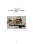
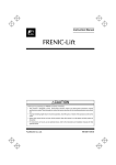
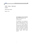
GB GB PKN10 serial node with colour LCD display User’s manual Bač 49a, 6253 Knežak, SLOVENIA tel: ++ 386 5 753 2006 fax: ++ 386 5 753 2007 email: [email protected] http://www.secelectro.com SEC Electronics PKN10 V0.3 page 1 GB PKN10 Serial node with colour LCD display Features 5,7” colour LCD display with adjustable indication and background colour. Car position and travel direction indication, time and date indication, colour image can be used for background, when lift is idle images can run in a slideshow, logo image can be shown all the time, when input14 is active, an image can be show with a predefined image name. Voice announcer with microSD card. Additional relay output for emergency call disable, when doors are open. Terminals for two pushbuttons with call indication, speaker output, emergency light battery and four additional inputs. Connector for output direction indicators. Call button illumination. Customizable floor display tables. Serial communication compatible with all SEC controllers. Figure 1: PKN10, simplified front view with dimensions (all in mm) SEC Electronics PKN10 V0.3 page 2 GB Technical specifications Unit size: 145 mm x 150 mm x 35 mm Display size: 115 mm x 82 mm Supply voltage: 24 V DC ±15% Supply current: max. 200 mA idle with backlight on, max. 350mA when charging battery (unit only, without load on the outputs) Digital outputs: max. 100 mA each Audio output: 5 W max. into 4 ohm Ambient temperature: max. 45°C Degree of protection: IP00 EMC: EN12015 in EN12016 Approvals: CE Figure 2: PKN10, rear view with connections SEC Electronics PKN10 V0.3 page 3 GB K1: (8-pin RJ-45 connector): SSL input K2: (8-pin RJ-45 connector): SSL output K3: (5-way 5,08 mm terminal block): external 24 V DC power supply and 12 V, 1,3 Ah battery connection K5: (2-way 5,08 mm terminal block): speaker output (max. 5W, min. 4 ohm) K6: Micro SD card socket K7: (10-way 5,08 mm terminal block): inputs and outputs, see figure 2 and the description below K8: (6/4-pin RJ-11 connector): direction indicator outputs K9: (6-way 3,91 mm terminal block): emergency call disable relay K10: (5-way 3,91 mm terminal block): CAN communication link (currently not used) J1, J2: jumpers to select power supply via SSL (closed) or external power supply via K3 (open) J3, J4: CAN bus termination (currently not used) D1: green LED (ON when device is working properly, blinking when communication doesn’t work). D2: green LED (CAN communication status, currently not used) D3: red LED (ON, when audio output is active) D4: green LED (ON when Micro SD card is inserted) K7 terminal description: terminal 1: 24 V DC (from external power supply) terminal 2: call DOWN terminal 3: 0V terminal 4: 24 V DC terminal 5: call UP terminal 6: 0V terminal 7: multifunction input 4 terminal 8: multifunction input 3 terminal 9: multifunction input 2 terminal 10: multifunction input 1 Terminal 1 is in Figure 2 on the left side. K8 pinout: pin 1: 0V pin 2: indicator up pin 3: indicator down pin 4: 0V Pin 1 is in Figure 2 on the left side. SEC Electronics PKN10 V0.3 page 4 GB Figure 3: standard call pushbutton/indicator wiring Figure 4: call pushbutton wiring for group operation Figure 4 shows possible call pushbutton wiring in a group (an example on the figure is for duplex) when each lift has its own serial line with PKN10. Call and display operation is correct in all modes, including when one of lifts doesn’t work or is switched off. Pushbutton backlight (E-type parameter F17) can be active on one PKN10 only, so landing button backlight should be switched off on all other lifts in the group with the parameter F22. SEC Electronics PKN10 V0.3 page 5 GB Power supply 24V DC is usually supplied to PKN10 via SSL serial link from the main controller module. However, the current that can be supplied via SSL link is limited to 1000 mA due to wiring and connector limitations. If jumpers J1 and J2 are removed, the module does not draw power from the SSL link and has to be connected to external power supply via K3. It is recommended to use K3 for power supply, if you have to use the SSL link to supply power, the number of PKN10 modules is limited to a maximum of 2. Please consult SEC Electronics if you have a specific configuration. Operation 1. Connect call pushbuttons/indicators, direction indicators, SSL link, optional battery and power supply if it is not from SSL link. 2. PKN10 performs the start-up procedure at power-on; its progress is shown on the display. Device configuration can be changed if a Micro SD card is inserted in the socket. Possible contents of SD card are described bellow in chapters “Micro SD card contents” and “Configuration file”. 3. Symbol “X” is displayed if the serial communication (SSL) doesn’t work properly with the main lift controller. 4. PKN10 device starts normal operation when serial line activity (SSL) is detected. Parameter setting Parameters on the PKN10 device are preset in the factory, so additional settings are not necessary. If changes are required the procedures are described in the following chapters. The Chapter on “Local configuration” is intended for all users while the chapter about “Micro SD card contents” is intended only for advanced users. Its use is only necessary to access some advanced device settings. Local configuration PKN10 device configuration can be made locally with three pushbuttons on the back side. To enter the Main menu, press the OK button. Local configuration consists of four options: 1. Set date/time 2. Parameters 3. Diagnostic display 4. Upgrade from microSD SEC Electronics PKN10 V0.3 page 6 GB With the UP and Down buttons navigate to the desired configuration and then press OK button to enter. To exit the configuration, navigate to “exit” and press OK button. Set date/time – to change the time, navigate to “set time” and press OK. With the UP and DOWN buttons, set the desired hour and press OK to move to minutes. Repeat the procedure for minutes and seconds. When you set the seconds and press the OK button, you will return to the date/time setting. To change the date, navigate to “set date” and press OK. With the UP and DOWN buttons, set the desired day and press OK to move to month. Repeat the procedure for month, year and day of week. When you set the day of week and press the OK button, you will return to the date/time setting. To return to main menu select return and press OK. Parameters - to change the parameters, navigate to “parameters” and press OK. Parameters are displayed line by line, as described in the chapter “Configuration file”. The active parameter is marked with a cursor and its value can be changed if you press the OK button and then you can change the value with the UP and Down buttons. To return press the OK button again. At the end, you can choose between two options: 1. Discard changes and return (no changes will be saved). 2. Save changes and return (all changes will be saved). Diagnostic display – has no editable parameters, its purpose is for monitoring the current status of the device. To exit press OK. Upgrade from microSD – to upgrade from microSD, you first must have valid files on the card as described in the chapter about “Micro SD card contents”. If you would like to update fonts, navigate to “upgrade font” and press OK. If your microSD card has a valid font file, you would have an option “proceed with font upgrade” otherwise you would have only “cancel font upgrade”. If the font update was successful, there will be a sign “Font upgrade OK” and you would be returned to the upgrade setting. If you would like to update firmware, navigate to “upgrade firmware” and press OK. If your microSD card has a valid firmware file, you would have an option “proceed with firmware upgrade” otherwise you would have only “cancel firmware upgrade”. If the firmware update was successful, there will be a sign “Firmware upgrade OK, please turn PKN10 ON/OFF” and you would be returned to the upgrade setting. To make the firmware update make effect, switch off the device and turn it back on. SEC Electronics PKN10 V0.3 page 7 GB MicroSD card contents PKN10.cfg: configuration file, contents is described below. If present, it is compared with device configuration in FLASH. In case they are different, configuration from card is copied to FLASH. That means this file (or micro SD card) shouldn’t be present if the configuration is changed locally (with pushbutton). Changes will be deleted at the next power up in this case. PKN10firmware.bin: file with a PKN10 firmware upgrade. It is prepared from hex file with a PKN09make.exe software tool. Firmware is changed only when this is requested in the local configuration. PKN10font.bin: file with fonts and symbols. It is prepared from monochrome bitmap fonts with the PKN09make.exe tool. It is usually upgraded together with the firmware. The upgrade shall be enabled in the local configuration. BMP images: PKN10 device checks bitmap image files on the SD card at start-up, so that those images can be shown as a screensaver, background, logo or a slide show. If an image has a name input1.bmp, then these image will be shown if input 1 is active and the same goes for input2,3,4. Image format and name specification: a) Input1: Name – “input1.bmp” Format – BMP 320 x 240 16bit, RGB565 b) Input2: Name – “input2.bmp” Format – BMP 320 x 240 16bit, RGB565 c) Input3: Name – “input3.bmp” Format – BMP 320 x 240 16bit, RGB565 d) Input4: Name – “input4.bmp” Format – BMP 320 x 240 16bit, RGB565 e) Background: Name – “background.bmp” Format – BMP 320 x 240 16bit, RGB565 f) Logo: Name – “logo.bmp” Format – BMP 220 x 60 16bit, RGB565 g) Other images : Name – not significant Format – BMP 320 x 240 16bit, RGB565 Wav files: PKN10 device checks wav files on the SD card at startup, for the voice announcer. These files should have a specially assigned name and format. Format can be 16kHz/8-bit mono or standard CD format 44.1kHz/16-bit stereo. Assigned names for wav files: SEC Electronics PKN10 V0.3 page 8 GB Lift S00_up.wav S01_down.wav S02_open.wav S03_close.wav S04_maxload.wa S05_overload.wav S06_error.wav S07_gong1.wav S08_gong2.wav status: elevator going up elevator going down doors opening doors closing maximal load reached lift overloaded out of service single gong (up) double gong (down) Floor: F01_*.wav F02_*.wav ... F32_*.wav floor 1 floor 2 floor 32 Important are only the first three characters Sxx for lift status and Fxx for floor and file type .wav! Configuration file The configuration file is a text file and can be edited with Windows Notepad. Settings in this file are shown in the local configuration except for the “out of service” text and the floor display table. 1. my_floor 0 – Not active, travel direction is shown according to the controller settings. 1..48 – PKN10 shows direction only when car is in the preset station. 2. display_starts_at the floor Default floor table is -2, -1, 0, 1, …, 48; display offset can be set with this parameter. Setting 1 means that “-2” is displayed in the lowest station; setting 2 means that “-1” is displayed in the lowest station and so on. This function works with the changed floor table too, see parameter “floor01..floor48”. 3. input1: Input I1 function definition (not active in PKN06 compatible mode) 0 - Not active. 1 – Fire alarm door A. 2 – Fire alarm door B. 4. input2: Input I2 function definition (not active in PKN06 compatible mode) 0 - Not active. 1 – Fire alarm door A. 2 – Fire alarm door B. 5. input3: Input I3 function definition (not active in PKN06 compatible mode) 0 - Not active. 1 – Landing door control. 2 – Fire fighter key. SEC Electronics PKN10 V0.3 page 9 GB 6. 7. 8. 9. 10. 11. 12. 13. 14. 15. input4: Input I4 function definition (not active in PKN06 compatible mode) 0 - Not active. 1 – Landing door control. 2 – Fire fighter key. slave_mode: Slave mode has to be active in case of more then one PKN10 device in the same floor. 0 – Not active, setting for the first or the only PKN09 device in the same floor. 1 – Acts as a slave, setting for the second or the third PKN10 device in the same floor. pkn06_compatible 0 – Serial line protocol is adapted to PKN10 (additional inputs, master/slave) and works only in combination with PKN10 devices and E-type CPU-B V0.57 or higher. 1 – PKN10 acts as PKN06 and can be used together with PKN06 devices, Node devices or older E-type CPU-B firmware. error_display: Displayed when lift doesn’t operate due to an error or it operates in a special mode (priority, fire, fireman, maintenance or evacuation drive). 0 – “No entry” sign, see picture. 1 - “X” sign; the same as for serial communication error. 2 - »Out of service« display; default is »OS«, see No entry sign the next parameter. os_text: Displayed when the lift doesn’t operate normally and parameter error_display is set to “2”. Default is »OS«, can be one or two characters long. Parameter can’t be set in the local configuration. os_mode: Display mode when lift doesn’t operate normally: 0 – Floor number and error message, defined by parameter error_display, are displayed alternatively. 1 – Floor number is shown all the time, there is no message that lift is not in function. 2 – An error message, defined with parameter error_display, is displayed all the time. There is no information about current car position. background_color (0..7 or 0x0000..0xFFFF; see explanation bellow). character_color (0..7 or 0x0000..0xFFFF; see explanation bellow). arrow_color (0..7 or 0x0000..0xFFFF; see explanation bellow). screen_saver: 0 - Off. 1 – Static bitmap image, the first found on the SD card. 2 – Bitmap images are changed in intervals, preset by parameter slide_show_delay. SEC Electronics PKN10 V0.3 page 10 GB 16. screen_saver_delay: 0 – Screensaver function is not active, current floor is shown all the time. 1..3600: Time of lift inactivity before screensaver is activated. Inactivity means that information shown by display is not changed. 17. slide_show_delay: Image change interval. 0 - Slide show is not active. 1..90: Image change interval; for proper operation parameter screen_saver must be set to “2” and screen_saver_delay to 1 second or more. 18. background_transparency_color: selects which color is considered transparent (is replaced with background image) for logo and arrows. 0 - Off. 1 – Black is transparent. 2 – White is transparent. 19. emergency_light: Selects display behaviour on battery power. 0 – normal operation (shows background image and communication error). 1 – emergency light mode (shows only white blank screen and date/time to maximise car illumination). 20. floor01 .. floor48: Floor designation (name) table from station 1 to 48. Name can be one or two characters long, allowed characters are 0..9, A..Z, Č, Š, Ž, Ć, Đ, +, -. Parameter can’t be set in local configuration. Colours can be selected from a predefined 0 to 7 palette or in 16-bit RGB format as hex constants. Bits 15-11 are for blue, bits 10 to 5 for green and bits 4 to 0 for red. Examples: 0x0000 = black, 0xFFFF = white, 0xF800 = blue, 0x07E0 = green, 0x001F = red. A predefined eight-colour palette, is available in local configuration, is: 0 = black, 1 = blue, 2 = green, 3 = light blue, 4 = red, 5 = violet, 6 = yellow, 7 = white SEC Electronics PKN10 V0.3 page 11