1
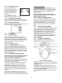
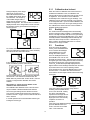
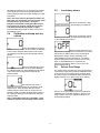
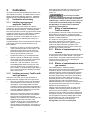
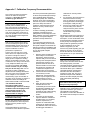
Reference Manual ToxiPro® Single Gas Detector Part #13-264-N3, Version 4 THE TOXIPRO®-NGSG PERSONAL PORTABLE GAS DETECTORS HAVE BEEN DESIGNED FOR THE DETECTION AND MEASUREMENT OF POTENTIALLY HAZARDOUS ATMOSPHERIC CONDITIONS. IN ORDER TO ASSURE THAT THE USER IS PROPERLY WARNED OF POTENTIALLY DANGEROUS ATMOSPHERIC CONDITIONS, IT IS ESSENTIAL THAT THE INSTRUCTIONS IN THIS REFERENCE MANUAL BE READ, FULLY UNDERSTOOD, AND FOLLOWED. ToxiPro®-NGSG Reference Manual Honeywell Analytics Part Number 13-264-N3 Version 4 Copyright 2015 by Honeywell Analytics, Inc. Lincolnshire, Illinois 60069 All rights reserved. No page or part of this operation manual may be reproduced in any form without written permission of the copyright owner shown above. Honeywell Analytics reserves the right to correct typographical errors. 2 Table of Contents OPERATING TEMPERATURE RANGE ................................................................................................................................................5 CERTIFICATIONS .............................................................................................................................................................................5 WARNINGS AND CAUTIONS .............................................................................................................................................................6 A. Signal Words ..........................................................................................................................................................6 B. Warnings .................................................................................................................................................................6 AVERTISSEMENTS ET MISES EN GARDE ...........................................................................................................................................7 A. Marquage ................................................................................................................................................................7 B. Avertissements ......................................................................................................................................................7 1. OVERVIEW ..........................................................................................................................................................................9 1.1 Methods of sampling .............................................................................................................................................9 1.2 Sensors ...................................................................................................................................................................9 1.2.1 ToxiPro sensor ranges ........................................................................................................................................9 1.2.2 ToxiPro O2 sensor ranges...................................................................................................................................9 1.2.3 ToxiPro O2 warm-up phase.................................................................................................................................9 1.3 Alarm and warning logic .......................................................................................................................................9 1.3.1 Gas alarms .........................................................................................................................................................9 1.3.2 Calibration and bump test due notices ................................................................................................................9 1.3.3 Battery replacement Warning .............................................................................................................................9 1.3.4 Low battery alarms .............................................................................................................................................9 1.3.5 Missing sensor during startup .............................................................................................................................9 1.3.6 Corrupt memory ................................................................................................................................................10 1.3.7 Vibrating Alarm Error ........................................................................................................................................10 1.3.8 Heartbeat Feature.............................................................................................................................................10 1.4 Functions ..............................................................................................................................................................10 1.4.1 Security beep ....................................................................................................................................................10 1.4.2 Latching alarms ................................................................................................................................................10 1.4.3 Enhanced Latching Alarm .................................................................................................................................10 1.4.4 Silence warning alarms .....................................................................................................................................10 1.5 IQ Dock Compatibility ..........................................................................................................................................10 1.6 Design components .............................................................................................................................................10 1.7 Standard accessories ..........................................................................................................................................11 1.8 Value pack kits .....................................................................................................................................................11 2. FIELD OPERATION ............................................................................................................................................................11 2.1 Turning the ToxiPro on ........................................................................................................................................11 2.1.1 Calibration due lockout .....................................................................................................................................12 2.2 Backlight ...............................................................................................................................................................12 2.3 Functions ..............................................................................................................................................................12 2.4 Calibration and bump test due notices ..............................................................................................................13 2.5 Low battery alarms ..............................................................................................................................................13 2.6 Sensor Over Range ..............................................................................................................................................13 2.7 Turning the ToxiPro off .......................................................................................................................................14 2.8 Always On Mode ..................................................................................................................................................14 2.8.1 Turning Off in Always On Mode ........................................................................................................................14 2.9 Sampling ...............................................................................................................................................................14 2.9.1 Sample draw kit usage .....................................................................................................................................14 3 3. CALIBRATION ...................................................................................................................................................................15 Verification of accuracy.......................................................................................................................................15 3.1.1 Verifying accuracy and response: ToxiPro O2 ..................................................................................................15 3.1.2 Verifying accuracy: ToxiPro with toxic gas sensor ............................................................................................15 3.2 Effect of contaminants on ToxiPro sensors ......................................................................................................15 3.2.1 Effects of contaminants on O2 sensors .............................................................................................................15 3.2.2 Effects of contaminants on toxic gas sensors ...................................................................................................15 3.3 Fresh air/zero calibration ....................................................................................................................................16 3.4 Functional (bump) testing (toxic sensor versions) ...........................................................................................16 3.5 Span Calibration (toxic sensor versions) ..........................................................................................................17 3.6 Failure to calibrate ...............................................................................................................................................17 3.6.1 Fresh air/zero calibration failure........................................................................................................................17 3.6.1.1 Causes of fresh air/zero calibration failures ...........................................................................................18 3.6.1.2 Forced fresh air/zero calibration .............................................................................................................18 3.6.2 Span calibration failure .....................................................................................................................................18 3.6.2.1 Sensor out of range (no CAL) ................................................................................................................18 3.6.2.2 Causes for span cal failure.....................................................................................................................18 3.7 Fresh air/zero calibration in a contaminated atmosphere ................................................................................18 4. MAINTENANCE ..................................................................................................................................................................19 4.1 Replacing batteries ..............................................................................................................................................19 4.2 Replacing sensors ...............................................................................................................................................20 4.3 Proper Cleaning ...................................................................................................................................................20 4.4 Storage ..................................................................................................................................................................20 5. PC-INSTRUMENT COMMUNICATIONS .................................................................................................................................20 5.1 Event logging .......................................................................................................................................................20 5.2 Instrument firmware upgrades............................................................................................................................21 5.3 Initiating communications ...................................................................................................................................21 6. EXPLODED VIEW AND BASIC PARTS LIST ............................................................................................................................21 APPENDICES .................................................................................................................................................................................22 Appendix A Sensor Cross-Sensitivity Chart.....................................................................................................................22 Appendix B Replacement Sensor List...............................................................................................................................22 Appendix C Calibration Frequency Recommendation.....................................................................................................23 HONEYWELL ANALYTICS WARRANTY GAS DETECTION PRODUCTS ................................................................................................24 General 24 Instrument & Accessory Warranty Periods .......................................................................................................................24 Sensor Warranty Periods ....................................................................................................................................................24 3.1 4 Operating Temperature Range The safe operating temperature range of the gas detector is -40 °C to +50 °C. Use of Honeywell Analytics Gas Detectors outside of the instrument’s specified operating temperature range may result in inaccurate and potentially dangerous readings. Certifications The ToxiPro®-NGSG carries the following certifications: UL Class I, Division 1, Groups A,B,C,D, Temp Code T4 UL Class II, Division 1, Groups E,F,G CSA Class I, Division 1, Groups A,B,C,D, Temp Code T4 CSA Class II, Division 1, Groups E,F,G UL International DEMKO A/S 09 ATEX 0823124 II 1 G Ex ia IIC T4 IECEx UL 09.0011 Ex ia IIC T4 Ga KTL, 13-KB4BO-0147X http://www.honeywellanalytics.com/~/media/honeywell-analytics/products/toxipro/documents/kcs- certificatejuarez-toxipro-13kb4bo0147x.pdf?la=en ® The ToxiPro -NGSG is in conformity with the following standards: UL 913, Seventh Edition CSA C22.2 No. 0-M91, C22.2 No. 25-1966, C22.2 No. 157-92 EN 60079-0:2009, EN 60079-11:2012, EN 60079-26:2007 IEC 60079-0:2007, IEC 60079-11:2011, IEC 60079-26:2006 5 Warnings and Cautions A. Signal Words The following signal words, as defined by ANSI Z535.4-1998, are used in the ToxiPro-NGSG Operator’s Guide. indicates an imminently hazardous situation which, if not avoided, will result in death or serious injury. indicates a potentially hazardous situation which, if not avoided, could result in death or serious injury. indicates a potentially hazardous situation, which if not avoided, may result in moderate or minor injury. CAUTION used without the safety alert symbol indicates a potentially hazardous situation which, if not avoided, may result in property damage. B. Warnings ToxiPro personal, portable gas detectors have been designed for the detection of either oxygen deficiencies or specific toxic gas accumulations. An alarm condition indicates the presence of a potentially lifethreatening hazard and should be taken very seriously. In the event of an alarm condition it is important to follow established procedures. The safest course of action is to immediately leave the affected area, and to return only after further testing determines that the area is once again safe for entry. Failure to immediately leave the area may result in serious injury or death. Use only Panasonic #CR2 in the ToxiPro. The accuracy of ToxiPro instruments equipped with toxic gas sensors should be checked periodically with known concentration calibration gas. Failure to check accuracy can lead to inaccurate and potentially dangerous readings. The ToxiPro O2 should be periodically calibrated in fresh air. A sensor that cannot be calibrated or is found to be out of tolerance must be replaced immediately. An instrument equipped with a toxic gas sensor that fails calibration may not be used until testing with known concentration test gas determines that accuracy has been restored, and the instrument is once again fit for use. Instruments equipped with an oxygen sensor that fail calibration may not be used until testing with fresh air determines that accuracy has been restored and the instrument is once again fit for use. Do not reset the calibration gas concentration setpoints in the ToxiPro unless the concentrations of your calibration gas differ from the concentrations of the calibration gas that is normally supplied by Honeywell Analytics for use in calibrating the ToxiPro. Use of non-standard calibration gas and/or calibration kit components when calibrating the ToxiPro can lead to dangerously inaccurate readings and may void the standard Honeywell Analytics warranty. Honeywell Analytics offers calibration kits and long-lasting cylinders of test gas specifically developed for easy calibration. Customers are strongly urged to use only Honeywell Analytics calibration materials when calibrating the ToxiPro. Substitution of components may impair intrinsic safety. For safety reasons the ToxiPro must be operated by qualified personnel only. Read, understand and follow the directions set forth in this reference manual before operating the ToxiPro. The ToxiPro has been tested for intrinsic safety in Explosive Gas/AIR (max. 21.0% O 2). 6 Avertissements et mises en garde A. Marquage La norme ANSI Z535.4-1998 définit certaines conventions quant aux marquages de sécurité. Conformément à ces conventions, le marquage utilisé dans le présent document est le suivant : situation présentant un danger immédiat qui, s'il n'est pas évité, peut entraîner des blessures graves, voire mortelles. situation présentant un danger potentiel qui, s'il n'est pas évité, peut entraîner des blessures graves, voire mortelles. situation présentant un danger potentiel qui, s'il n'est pas évité, peut entraîner des blessures légères ou sans gravité. MISE EN GARDE (sans le symbole d'alerte) situation présentant un danger potentiel qui, s'il n'est pas évité, peut entraîner des dommages sur les biens. B. Avertissements Les détecteurs de gaz portables ToxiPro sont conçus pour déceler le manque d'oxygène ou l'accumulation de gaz toxiques spécifiques. Le déclenchement d'une alarme indique la présence d'un danger potentiellement mortel et doit être pris très au sérieux. En cas de déclenchement d'une alarme, il est impératif de suivre les procédures établies. Le comportement le plus sûr consiste à quitter immédiatement la zone concernée et à revenir uniquement si les résultats des tests complémentaires effectués démontrent que cette zone est de nouveau sûre et accessible. Le non-respect de ces instructions peut entraîner des blessures graves, voire mortelles. Le détecteur ToxiPro doit être alimenté uniquement par une pile Panasonic CR2. La précision des détecteurs ToxiPro équipés de capteurs de gaz toxiques doit être vérifiée régulièrement en appliquant une concentration connue de gaz d'étalonnage. Si cette vérification n'est pas réalisée, les mesures de l'appareil risquent d'être imprécises, entraînant ainsi un danger potentiel pour l'utilisateur. Le détecteur ToxiPro O2 doit être étalonné régulièrement à l'air libre. Tout capteur ne pouvant être étalonné ou hors de sa plage de tolérance doit être remplacé immédiatement. Si l'étalonnage d'un capteur de gaz toxiques n'est pas concluant, le détecteur concerné ne doit en aucun cas être utilisé. Pour que celui-ci soit de nouveau utilisable, il convient préalablement de le tester en appliquant une concentration connue de gaz de test pour vérifier la précision de l'appareil et déterminer selon les résultats de ce test s'il est opérationnel. De même, si l'étalonnage d'un capteur d'oxygène n'est pas concluant, le détecteur concerné ne doit en aucun cas être utilisé. Pour que celui-ci soit de nouveau utilisable, il convient préalablement de le tester à l'air pur pour vérifier la précision de l'appareil et déterminer selon les résultats de ce test s'il est opérationnel. Les seuils de concentration de gaz d'étalonnage du détecteur ToxiPro ne doivent jamais être réinitialisés sauf si la concentration du gaz d'étalonnage utilisé diffère de celle du gaz d'étalonnage normalement fourni par Honeywell Analytics pour l'étalonnage de l'appareil. Toute utilisation de gaz d'étalonnage et/ou de matériel d'étalonnage non standard pour étalonner le détecteur ToxiPro risque d'entraîner des mesures imprécises dangereuses et d'annuler la garantie Honeywell Analytics standard. Honeywell Analytics propose des kits d'étalonnage et des bouteilles de gaz de test longue durée spécialement conçus pour faciliter l'étalonnage. Nous vous recommandons vivement d'utiliser uniquement le matériel d'étalonnage Honeywell Analytics pour étalonner le détecteur ToxiPro. Tout remplacement des composants du détecteur risque de compromettre la sécurité intrinsèque de l'appareil. Pour des raisons de sécurité, le détecteur ToxiPro doit être utilisé uniquement par du personnel qualifié. Les instructions du présent manuel doivent impérativement être lues, comprises et suivies avant d'utiliser l'appareil. Le détecteur ToxiPro a fait l'objet de tests de sécurité intrinsèque avec de l'air/du gaz explosif (21,0% O2 maxi). 7 8 1. Custom, TWA (Time Weighted Average) (if enabled) and STEL (Short Term Exposure Limit) (if enabled). The custom alarm level can be set to a level greater than/equal to the danger alarm level for toxic sensors and less than/equal to danger level for oxygen sensors using the IQ System software. The custom alarm is a latching alarm. The custom alarm looks and sounds similar to the DANGER alarm but, with the warning symbol turned on and the DANGER icon not being set. If the custom alarm level has been reached then the alarm can only be silenced by putting the instrument in the dock (successful IrDA connection) or successful connection to BioTrak. If the custom alarm value is zero then the custom alarm is disabled and “OFF” will appear on the instrument’s LCD during the startup sequence. If the danger alarm has been disabled then the custom alarm is also disabled. Overview The ToxiPro is a single sensor gas detector that can be configured to detect either oxygen (O2) or one of a variety of toxic gases. The ToxiPro’s sensor type is shown on the front of the instrument and is also shown on the display during the start up sequence. The ToxiPro includes numerous features designed to meet specific user requirements. 1.1 Methods of sampling The ToxiPro may be used in diffusion mode, or with the manual sample draw kit that is available separately. In either mode, the atmosphere must reach the sensor for the instrument to register a reading. In diffusion mode, the atmosphere reaches the sensor by diffusing through the sensor port on the front of the instrument. Normal air movements are enough to carry the sample to the sensor. During remote sampling, the gas sample is drawn into the sensor compartment through the probe assembly and a length of tubing. See section 2.9 for more details on sampling the atmosphere. 1.2 Note: In the standard ToxiPro configuration with toxic gas sensors, the STEL and TWA alarms are not enabled. The STEL and TWA alarms may be enabled at the factory or through BioTrak software. Call Honeywell Analytics for more details. 1.3.2 Sensors All versions of the ToxiPro except the O2 model use an electrochemical toxic gas sensor. The ToxiPro O2 uses a galvanic oxygen sensor. Both types of sensor have been designed to minimize the effects of common interfering gases. These sensors provide accurate, dependable readings for gases commonly encountered in industrial applications. A sensor cross sensitivity chart is provided in Appendix A at the back of this manual. 1.2.1 Calibration and bump test due notices The ToxiPro includes bump test and calibration due notices. For more information on the calibration due notices, see section 2.4 below. 1.3.3 Battery replacement Warning If a new battery has been installed or the existing battery was removed and replaced the ToxiPro will show “F 0” on the display and will beep 6 times upon startup. It will then go into the set time/date mode. ToxiPro sensor ranges Specific toxic sensor ranges and resolutions are provided in the sensor replacement chart in Appendix B. 1.2.2 ToxiPro O2 sensor ranges The oxygen sensor used in the ToxiPro O2 has a range of 0-30% by volume. 1.2.3 ToxiPro O2 warm-up phase 1.3.4 Low battery alarms The ToxiPro O2 requires a one-time, 15-minute warm-up phase prior to initial activation. See section 2.1 for further details. The ToxiPro is designed with two battery warning alarms that are activated when the battery voltage is reduced to specific levels. 1.3 1.3.1 For more details on the battery alarm, see section 2.5 below. Alarm and warning logic Gas alarms 1.3.5 ToxiPro gas alarms are user-adjustable and may be set anywhere within the range of the specific sensor. When an alarm set point is exceeded a loud audible alarm sounds. In the warning state the LED’s will flash, yellow. In the danger state the LED’s will flash, red. Two oxygen alarm set points have been provided for ToxiPro O2 instruments. The danger alarm is sounded for oxygen deficiency and the warning alarm is sounded for oxygen enrichment. ToxiPro instruments equipped with a toxic gas sensor have up to four alarm set points: Warning, Danger, Missing sensor during startup If the ToxiPro fails to detect a sensor during startup, it will show “F 1” with the caution symbol and then shut itself off. For more details, see section 2.1. 9 1.3.6 Latch Acknowledgement A latched alarm latch can be acknowledged by two methods. The first is either by mode press or inserting the instrument into the dock. The second is by dock insertion only. The method is selectable in the IQ System template. Corrupt memory The ToxiPro continuously monitors its onboard memory. If the instrument determines that the memory is corrupt, it will display “F 4” and proceed to shut itself off. If “F 4” is displayed, contact Honeywell Analytics for further details. 1.3.7 Note: For more information on creating and assigning templates, please refer to the Database Manager Reference manual. 1.4.4 Vibrating Alarm Error 1.3.8 Heartbeat Feature A blinking heart is an active indicator, notifying the user that the instrument is operating normally. 1.5 1.4 1.4.1 IQ Dock Compatibility The ToxiPro must be equipped with instrument firmware version 4.30 or higher to be compatible with the IQ Express Docking Station. The IQ Express Dock is an automatic calibration station coupled with a data management system. The IQ Express Dock must be equipped with firmware version 6.53 or higher. Instrument firmware in the ToxiPro may be upgraded at any time. See section 5.2 below for details on software upgrades. Functions Security beep The ToxiPro includes a security beep that can be enabled or disabled with BioTrak software through the PC’s IrDA port. If the security beep is enabled, the ToxiPro will emit a short beep coupled with an LED flash at a specific interval to remind the user that the instrument is active. 1.4.2 Silence warning alarms The ToxiPro’s audible and vibrating (if so equipped) alarms can be turned off during an alarm condition by pressing the MODE button if this function has been enabled with BioTrak software. The visual warning alarm light and readings will continue to indicate the alarm. If the vibrating alarm fails “F 6” will be shown on the display. Contact Honeywell Analytics for further details. 1.6 Design components Case: The instrument is enclosed in a solid PC (polycarbonate) case with TPE (rubber) overmold. Latching alarms The ToxiPro includes latching alarms that can be enabled or disabled with BioTrak software through the PC’s IrDA port. With the alarm latch enabled, the audible and visible alarms will continue to sound even after the atmospheric hazard has cleared. To turn the alarm off once the hazard is no longer present, simply press the MODE button. 1.4.3 Enhanced Latching Alarm Note: V9.20 or greater ToxiPro firmware and V8.00 or greater is required of all IQ System software to support the Enhanced Latching Alarm. The enhanced latching capability can be enabled for the danger alarm using an IQ System template and apply the template in ToxiPro IQ Express. The user can specify the duration for latching of the Danger alarm. When the instrument goes into the danger alarm for greater than or equal to the user defined duration for latching then the alarm is latched. When the alarm is latched and if the gas level goes below the alarm level, the audible and visual alarms will continued. If alarm latching is enabled and the instrument is in alarm for less than the latching duration, the alarm will not latch when the gas level drops below the alarm level. Figure 1: Exterior front view Front face: The front face of the instrument houses the LCD display, MODE button, sensor port, LED alarm and audible alarm port. LCD display: The liquid crystal display (LCD) shows gas readings, messages and other information. A builtin, manually-activated backlight allows the display to be read even in low light conditions. LED / IrDA port: The LED also functions as the IrDA port. 10 MODE button: The large push-button on the front of the instrument is called the MODE button. The MODE button is used to turn the ToxiPro on and off, to turn on the backlight, to view the MAX, STEL (if enabled) and TWA (if enabled) screens and to initiate the automatic calibration sequences. Sensor port: The sensor port is located at the upper left corner of the instrument. A filter prevents unwanted contaminants from entering the sensor. Audible alarm port: A cylindrical resonating chamber contains the loud audible alarm. Visual alarm (LED) Windows: A bright LED (LightEmitting Diode) alarm light provides a visual indication of the alarm state. Belt Clip: The belt clip attaches to the bottom surface of the instrument. 1.7 → When the ToxiPro O2 warm-up period concludes, the screen will be completely blank. ToxiPro models equipped with a toxic gas sensor do not require an initial warm up period. With the blank screen shown, press and hold the MODE button for 5 seconds to initiate the start-up sequence. At start-up, the ToxiPro will automatically go through a basic electronic self-test sequence that will take approximately thirty seconds. During the self-test sequence, all sections of the display will be lit, the display backlight will momentarily turn on and the audible alarm will “chirp”. If the instrument fails to detect the sensor during startup, “F 1” will be displayed with the caution symbol following the display test screen. If “F 1” is shown, the instrument will automatically shut down in approximately 5 seconds. See Section 4.2 of this manual for instructions on accessing the sensor compartment. Once the ToxiPro recognizes the sensor, it will display the software version using two screens. Standard accessories Standard accessories with every ToxiPro include installed sensor and lithium battery, reference manual and calibration/sample draw adapter. Optional accessories include manual sample draw kit (hand-aspirated), vibrating alarm, Datalogger Upgrade and BioTrak software kit. 1.8 Value pack kits ToxiPro value packs include all standard accessories, plus calibration fittings, 34-liter cylinder of calibration gas, and fixed flow rate regulator in a foam-lined, hardshell carrying case. 2. Field Operation Field operation of the ToxiPro is controlled entirely through the MODE button, which is located on the front of the instrument. The MODE button is used to turn the ToxiPro on and off, to turn on the backlight, to access MAX, STEL (if enabled) and TWA (if enabled) gas readings for the current session and to initiate calibration. 2.1 → The serial number screens will then be shown: Note that the 9 digit serial number can not fit on a single screen, so it is shown on three screens. In this case, the instrument serial number is 481098190. Turning the ToxiPro on The ToxiPro is effectively disabled when it leaves the Honeywell Analytics factory. Upon arrival, the ToxiPro’s display will be blank. The ToxiPro O2 will show the negated horn icon. → → Datalogging versions will then show the “dL” screen. Once the sensor is recognized, the instrument will display the sensor type. The warning alarm level will then be displayed, followed by the danger alarm level. During the display of the warning alarm level, the LED alarm light will be flashed twice and the audible warning alarm will be sounded twice. or To initialize the instrument, press the MODE button for 5 seconds. ToxiPro O2 models will proceed with a 15-minute countdown while the oxygen sensor stabilizes. Note: The 15-minute sensor warm-up period is only necessary for the initial start-up of ToxiPro O2 models. 11 2.1.1 During the display of the danger alarm level, the LED visual alarm will be flashed twice and the audible danger alarm will be sounded twice. The frequency of the audible danger alarm is higher than the frequency of the audible warning alarm. The custom alarm if enabled is displayed similar to the danger alarm, but the LCD has the triangular warning symbol without the Danger or Warning symbol. Calibration due lockout When the ToxiPro’s calibration due lockout function is enabled and calibration is due, the calibration due warning will be shown at instrument start up and can not be bypassed. The instrument must be calibrated immediately before it will show any gas readings. The calibration may be performed manually, or by placing it in an IQ Express Dock. Upon successful calibration, the ToxiPro will proceed to the current gas readings screen. The calibration due lockout function can be enabled or disabled with BioTrak software. 2.2 Backlight The ToxiPro includes a backlight that is automatically turned on during an alarm condition. The backlight can also be manually activated while the current gas reading is displayed by pressing the MODE button once. When manually activated, the backlight will automatically turn itself off in about twenty seconds. If activated by an alarm condition, the backlight will remain on until the instrument is no longer in alarm. → 2.3 Functions From the current gas reading screen, press the MODE button once to activate the backlight. Press MODE again to scroll through the screen options. Once the backlight has been lit, press MODE once more to view the MAX gas values screen. The MAX figure represents the highest gas value reading that has been recorded by the instrument during the current operating session. ToxiPro O2 models will sequentially display both the highest and the lowest readings that have been recorded by the instrument in the current operating session. From the MAX screen, press the MODE button to view the time screen. A dot below the colon between the hours and the minutes digits indicates afternoon/evening hours (pm). For ToxiPro instruments with a toxic sensor and with the STEL and TWA alarms enabled, the ToxiPro will briefly show the STEL and TWA alarm levels. → If the calibration due reminder is enabled and calibration is due, the following screens will be shown. → Press the MODE button to acknowledge the calibration due reminder. If the instrument shuts off when the MODE button is pressed with “cal due shown”, then the ToxiPro is configured with calibration due lockout enabled. See section 2.1.1 below for more details on the calibration due lockout function. The Calibration Due Reminder and Lockout functions may be enabled or disabled with BioTrak Software. The current gas readings screen will then be shown. Toxic sensor models should show 0 if the instrument is located in fresh air. Oxygen sensor models should show 20.9 in fresh air. In normal operation the screen alternates between gas reading and sensor type. 10:45 am 10:45 pm If the STEL (Short Term Exposure Limit) alarm is enabled, press the MODE button once to view the STEL reading. The STEL value displayed represents the average value of the instrument readings for the target gas for the most recently completed 15 minutes of operation. If the TWA (Time Weighted Average) alarm is enabled, press the MODE button once more to view the current TWA value. TWA values are 12 calculated by taking the sum of the instrument readings for the target gas for the current operating session in terms of parts-per-million-hours and dividing by an eighthour period. 2.5 Note: Due to the nature of the TWA calculation, the TWA value can accumulate over time and may cause the instrument to go into alarm. Honeywell Analytics recommends resetting the TWA value at the beginning of any work shift by turning off the instrument and then turning it back on again. Press the MODE button again to return to the current gas readings screen. 2.4 Low battery alarms When there are less than 7 days of battery life remaining, the low battery icon will be lit. Calibration and bump test due notices When there are less than 8 hours of battery life remaining, the triangular warning symbol on the LCD will also be shown. When the calibration due notice is enabled and the ToxiPro is due for fresh air calibration “0-CAL” will be displayed at the bottom of the current gas readings screen along with the triangular warning symbol. When the battery reaches a level where it can no longer power the instrument, the ToxiPro will sound a low battery alarm for two minutes while displaying the danger, caution and battery icons. Press MODE to turn the instrument off. The battery must be replaced before the instrument can be used again. If the MODE button is not pressed, the instrument will remain in alarm for as long as it can before shutting itself off. When the calibration due notice is enabled and the ToxiPro is due for span calibration the calibration bottle icon will be displayed at the bottom of the current gas readings screen along with the warning symbol. 2.6 Sensor Over Range The ToxiPro will go into alarm if a sensor is exposed to a concentration of gas that exceeds its established range. In the case of an H2S reading that exceeds 200 PPM, the ToxiPro will go into the danger alarm state and the display will show “OL” in place of the sensor reading. The bump test due notice is designed for instruments that are processed in an IQ Express Dock. When the bump test due notice is enabled and the ToxiPro is due for a bump test, the calibration bottle icon will be displayed at the bottom of the current gas readings screen without the triangular warning symbol. Note: If an IQ Express Dock is unavailable, a span calibration will also reset the bump test due notice. After an over range condition occurs the unit must be calibrated under controlled conditions. When an over range condition occurs, the calibration indicators are automatically activated. 13 2.7 It is also possible to use the ToxiPro to sample remote locations with the hand-aspirated sample-draw kit that is available separately. During remote sampling, the gas sample is drawn into the sensor compartment through the probe assembly and a length of tubing. Turning the ToxiPro off To turn the ToxiPro off, press and hold the MODE button down until the instrument chirps three times and OFF is displayed. Once OFF is displayed, release the MODE button. The instrument has been successfully turned off when the display goes blank. The ToxiPro and manual sample draw kit are delivered with polyester urethane (fuel-resistant) tubing part number 53-001. This material is completely compatible with the toxic gases CO and H2S. When using the ToxiPro and sample draw kit to sample with any of the gas types and tubing lengths listed in the chart below, FEPlined tubing (part number 53-036) should be used. If Always On Mode is enabled see section 2.8.1 for instructions for turning off the ToxiPro. 2.8 Always On Mode The ToxiPro may be configured so that it may not be turned off with the MODE button. In Always On Mode, the MODE button is used to reset the MAX, STEL and TWA calculations. Press and hold the MODE button until the instrument chirps three times and “on” is displayed. After the “on” screen, the ToxiPro will proceed through the standard startup sequence until the current gas readings screen is shown. MAX, STEL and TWA calculations will be reset. Always On Mode may be enabled or disabled with BioTrak software. 2.9.1 1. Turning Off in Always On Mode 2. BioTrak software must be used to turn the ToxiPro off when it is in Always on Mode. BioTrak is available at: 1. 2. 3. 4. 2.9 Tubing Length CL2, CLO2 Up to 10 ft/3m Max. HCN Up to 100 ft/30m Max. SO2, NO2, PH3, NH3 > 10 ft/3m up to 100 ft/30m Max. Standard polyester urethane (fuel-resistant) tubing (part number 53-001) can be used otherwise. Use of other types of tubing, or beyond recommended length(s), may cause inaccurate and potentially dangerous readings that could result in serious injury or death. Note: The ToxiPro must be turned off to replace the battery. See section 2.8.1. 2.8.1 Gas Type 3. http://www.honeywellanalytics.com Open BioTrak and select ToxiPro. Select “Configure” in the software. Hold the MODE button down for about 10 seconds until IrDA is shown and establish the connection with the PC. The Never Turn Off option appears at the bottom left of every page in the configuration window. Click the Turn Off button. 4. 5. Sampling The ToxiPro may be used in either diffusion or sampledraw mode. In either mode, the gas sample must enter the sensor compartment for the instrument to register a gas reading. In diffusion mode, the atmosphere reaches the sensor by diffusing through the sensor port on the front of the instrument. Normal air movements are enough to carry the sample to the sensor. The sensor reacts quickly to changes in the concentration of the gas being measured. 6. Sample draw kit usage Connect the shorter section of tubing from the squeeze bulb to the sample draw adapter. Then connect the longer section of tubing from the squeeze bulb to the sample probe. Slide the sample draw adapter into the sensor port on the ToxiPro and secure it. Cover the end of the sample draw probe assembly with a finger, and squeeze the aspirator bulb. If there are no leaks in the sample draw kit components, the bulb should stay deflated for a few seconds. Insert the end of the sample probe into the location to be sampled. Squeeze the aspirator bulb several times to draw the sample from the remote location to the sensor compartment. Allow one squeeze of the bulb for every one foot of sampling hose for the sample to reach the sensors. Continue to squeeze the bulb for an additional 45 seconds or until readings stabilize. Note the gas measurement readings. Hand aspirated remote sampling only provides continuous gas readings for the area in which the probe is located when the bulb is being continuously squeezed. Note: Each time a reading is desired, it is necessary to squeeze the bulb a sufficient number of times to bring a fresh sample to the sensor compartment and to continue to squeeze the bulb until readings stabilize. 14 3. If the readings are inaccurate, the instrument must be span calibrated before further use as discussed in section 3.5. Calibration The ToxiPro features fully automated fresh air/zero and span calibration functions. The MODE button is used to initiate the automatic calibration sequence. Calibration adjustments are made automatically by the instrument. 3.1 3.1.1 The accuracy of ToxiPro instruments equipped with toxic gas sensors should be checked periodically with known concentration calibration gas. Failure to check accuracy can lead to inaccurate and potentially dangerous readings. Verification of accuracy Verifying accuracy and response: ToxiPro O2 See Appendix C for a discussion of calibration frequency recommendations. To verify the accuracy of the ToxiPro O2, take the ToxiPro O2 to an area where the atmosphere is known to be fresh and check the readings. If the readings differ from those expected in fresh air (oxygen monitors should read 20.9% in fresh air), then a fresh air/zero calibration adjustment must be made as discussed below in section 3.3. If fresh air is not available, see section 3.7 below for instructions for calibrating the ToxiPro O2 in contaminated air. Honeywell Analytics also recommends that the response of the oxygen sensor be regularly verified by any of these methods: Process the ToxiPro O2 in an IQ Express Dock that has a cylinder of calibration gas containing 18.0% oxygen (or less) connected to the gas port and proceed with the oxygen bump test. Breath test: Hold your breath for 10 seconds, then slowly exhale directly onto the face of the sensor (in the same way you would to fog up a piece of glass). If the descending oxygen alarm is set to 19.5%, the instrument should go into alarm after a few seconds. Effect of contaminants on ToxiPro sensors The atmosphere in which the ToxiPro is used can have lasting effects on the sensors. Sensors may suffer losses in sensitivity leading to degraded performance if exposed to certain substances. The ToxiPro O2 uses a galvanic oxygen sensor, while toxic sensor versions of the ToxiPro use an electrochemical toxic gas sensor. Different types of sensors use different detection principles, so the conditions that affect the accuracy of the sensors vary from one type of sensor to the next. Expose the O2 sensor to a known concentration of gas containing less than 19.0% oxygen. If the descending oxygen alarm is set to 19.5% the instrument should go into alarm a few seconds after the gas reaches the sensor face. 3.1.2 3.2 3.2.1 Effects of contaminants on O2 sensors Oxygen sensors may be affected by prolonged exposure to "acid" gases such as carbon dioxide. The oxygen sensors used in Honeywell Analytics instruments are not recommended for continuous use in atmospheres containing more than 25% CO2. 3.2.2 Effects of contaminants on toxic gas sensors Honeywell Analytics’s “substance-specific” electrochemical sensors have been carefully designed to minimize the effects of common interfering gases. “Substance-specific” sensors are designed to respond only to the gases that they are supposed to measure. The higher the specificity of the sensor, the less likely the sensor will react to other gases, which may be incidentally present in the environment. For instance, a “substance-specific” carbon monoxide sensor is deliberately designed not to respond to other gases that may be present at the same time, such as hydrogen sulfide (H2S) and methane (CH4). Although great care has been taken to reduce crosssensitivity, some interfering gases may still have an effect on toxic sensor readings. In some cases the interference may be positive and result in readings that are higher than actual. In other cases the interference may be negative and produce readings that are lower than actual and may even cause the instrument to display negative readings for the target gas. Verifying accuracy: ToxiPro with toxic gas sensor Verification of accuracy is a two-step procedure for ToxiPro instruments equipped with a toxic gas sensor: 1. Step one is to take the ToxiPro to an area where the atmosphere is known to be fresh and check the readings. If the readings differ from those expected in fresh air (instruments equipped with a toxic sensor should read 0 PPM in fresh air), then a fresh air calibration adjustment must be made as discussed below in section 3.3. 2. Step two is to test sensor response by exposing the sensor to a test gas of known concentration. This is known as a functional (bump) test. Readings are considered to be accurate when the display is between 90% and 120% of the expected values as given on the calibration gas cylinder. If readings are accurate, there is no need to adjust your gas detector. See section 3.4 for further details concerning the functional/bump test. See Appendix A for cross-sensitivity data. 15 3.3 2. 3. Fresh air/zero calibration To initiate the fresh air/zero calibration: 1. From the current gas reading screen, press the MODE button three times within two seconds to begin the fresh air/zero calibration sequence. The ToxiPro will briefly display “CAL” and then begin a 5-second countdown with the 0-CAL icon lit. 4. Make sure the instrument is located in fresh air. Verify that the current gas readings match the concentrations present in fresh air. The reading for toxic gases should be 0 parts-per-million (PPM) in fresh air. If the reading is anything other than 0 PPM proceed to section 3.3 and perform a fresh air/zero calibration before continuing. Apply the calibration gas as shown in figure 3.4. → 2. Press the MODE button before the end of the 5second countdown to begin the fresh air/zero calibration. The fresh air/zero calibration has been successfully initiated when the ToxiPro alternates between the following two screens: ↔ 3. Figure 3.4: Proper bump-test/span calibration set-up for toxic sensor-equipped instruments For instruments equipped with a toxic gas sensor, the fresh air/zero calibration is complete when the instrument begins a second 5-second countdown for the span calibration. If span calibration is not required, allow the countdown to reach 0 without pressing the MODE button. For further instructions concerning the span calibration of toxic sensor-equipped models, proceed to section 3.5. For ToxiPro O2 models, calibration is complete when the instrument returns to the current gas readings screen. If the fresh air/zero calibration attempt fails, proceed to section 3.6.1. Note: ToxiPro instruments equipped with a chlorine dioxide (ClO2) sensor require a chlorine dioxide generator as a calibration gas source. 5. Wait for the readings to stabilize. (Forty-five seconds to one minute is usually sufficient.) 6. Note the readings. Readings are considered accurate if they are between 90% and 120% of the expected value. If the readings are considered accurate, then the instrument may be used without further adjustment. If readings are considered inaccurate, the instrument must be adjusted using the “span” calibration procedures discussed in section 3.5 before further use. Fresh air/zero calibrations may only be performed in an atmosphere that is known to contain 20.9% oxygen and 0 PPM toxic gas. Performing the fresh air/zero calibration in an atmosphere that is not comprised of 20.9% oxygen and 0 PPM toxic gas may lead to inaccurate and potentially dangerous readings. 3.4 Functional (bump) testing (toxic sensor versions) The accuracy of ToxiPro instruments may be verified at any time by a simple functional (bump) test. To perform a functional (bump) test, do the following: 1. Turn the ToxiPro on and wait at least three minutes to allow the readings to fully stabilize. If the sensor has just been replaced, it must be allowed to stabilize prior to performing a functional (bump) test. See section 4.2 for further details. 16 3.5 Note: The maximum span calibration adjustment value shown is an indication of the relative health of the sensor. As a sensor loses sensitivity, the maximum adjustment level will approach the calibration gas concentration, letting you know when the sensor is losing sensitivity. Once the maximum span adjustment descends to within 10% of the calibration gas concentration, it is time to order a new sensor. 4. Following successful calibration, the instrument will display the gas reading with the negated horn icon until the reading drops below the alarm threshold. Span Calibration (toxic sensor versions) Span calibration should be performed when a functional (bump) test has shown that the instrument’s gas readings are not between 90% and 120% of the expected values as given on the calibration gas cylinder (as discussed in section 3.4). Prior to performing a span calibration, perform a fresh air/zero calibration as discussed in section 3.3. After successful completion of the fresh air/zero calibration, the instrument will begin a second five-second countdown with the calibration gas bottle icon highlighted. Disconnect the calibration assembly immediately after calibration. 1. Use of non-standard calibration gas and/or calibration kit components when calibrating the ToxiPro can lead to inaccurate and potentially dangerous readings, and may void the standard Honeywell Analytics Gas Detection Warranty. Press the MODE button before the countdown is complete to initiate the span calibration. The display will alternate between “GAS” and the expected concentration of calibration gas. 3.6 Failure to calibrate 3.6.1 Fresh air/zero calibration failure ↔ 2. Apply calibration gas as shown above in figure 3.4. Once calibration gas is detected, the readout will change to show the gas reading. Note that the negated horn symbol is shown at lower left to indicate that the alarms are not operating because the instrument is in calibration mode. Note: ToxiPro instruments equipped with a chlorine dioxide (ClO2) sensor require a chlorine dioxide generator as a calibration gas source. 3. In the event of fresh air/zero calibration failure, the “no” and “CAL” screens will be alternately displayed as shown below with the “0-CAL” segment lit. The instrument will then return to the gas reading screen. ↔ The calibration is fully automatic from this point on. Once the instrument successfully completes the span calibration, it will emit three short beeps and display the maximum span calibration adjustment value for two seconds. Following a fresh air/zero calibration failure, the triangular warning symbol will be lit and the “0-CAL” indicator will flash until a successful fresh air/zero calibration is performed. 17 3.6.1.1 Note: If the Calibration Due Lockout is enabled, the ToxiPro will turn itself off following a failed calibration attempt. Causes of fresh air/zero calibration failures Fresh air/zero calibration failures often result from the attempt to calibrate the instrument in a contaminated atmosphere. Fresh air/zero calibration failures in the ToxiPro O2 can also result from an oxygen sensor that has failed. 3.6.1.2 3.6.2.2 Forced fresh air/zero calibration If a fresh air/zero calibration fails in an atmosphere known to be fresh, the ToxiPro can be forced to fresh air calibrate as follows. 1. Follow instructions 1 and 2 in section 3.3 to begin the fresh air/zero calibration sequence. 2. As soon as the alternating right and left 0’s are shown on the screen, press and hold the MODE button. 3.7 The forced fresh air/zero calibration is complete when the instrument emits three short beeps and then moves on to the span calibration procedure. Performing the forced fresh air calibration in a contaminated atmosphere will lead to inaccurate and potentially dangerous readings. 3.6.2 Span calibration failure The ToxiPro is designed to recognize two distinct types of span calibration failures: failures that occur due to sensor response outside the sensor’s normal range for calibration and failures that occur when the instrument fails to recognize any calibration gas whatsoever. 3.6.2.1 Fresh air/zero calibration in a contaminated atmosphere To perform a fresh air calibration in a contaminated atmosphere, it is necessary to use special calibration gas, whose composition is identical to that of fresh air. Honeywell Analytics offers the “Zero Air” calibration gas cylinder as part number 54-9039, which contains 0 PPM toxic gas and 20.9% oxygen. 1. Apply “Zero Air” calibration gas to the instrument as shown above in figure 3.4 for at least 15 seconds or until the readings fully stabilize. 2. Perform the fresh air/zero calibration procedure as described in section 3.3 while continuing to flow gas to the sensor. 3. Once the fresh air/zero calibration is complete, disconnect the calibration assembly. If the ToxiPro is equipped with a toxic gas sensor, proceed to the span calibration procedure if necessary as described in section 3.5. ↔ 3. Causes for span cal failure Span calibration failures can be caused by: 1. Expired calibration gas. 2. Calibration gas whose concentration fails to match the concentration expected by the instrument. 3. Inappropriate regulator. The ToxiPro must be calibrated using a 1.0 liter/minute fixed flow regulator. 4. Sensor failure. Sensor out of range (no CAL) If the instrument recognizes calibration gas, but the sensor response is not within the range to calibrate the instrument, span calibration will fail and the “no” and “CAL” screens will be alternately displayed. ↔ After displaying “no” and “CAL” times, the instrument will return to the current gas readings screen and the warning symbol and the calibration bottle icon will be shown, which signifies that the instrument failed the last attempt to span calibrate. 18 4. Maintenance 4.1 Replacing batteries Removal or replacement of the lithium battery in potentially combustible atmospheres may compromise intrinsic safety. The lithium battery used in the ToxiPro may only be removed or replaced in an atmosphere that is known to be non-hazardous. To replace the battery: 1. Turn the ToxiPro off. If the ToxiPro is in Always On Mode, see section 2.8.1 for further instructions. The next five steps describe programming the time and date. 7. Press and release the MODE button to advance the setting by one. Hold the MODE button down to scroll rapidly. Afternoon and evening hours are differentiated by a dot below the colon on the display. Note: Failure to turn the ToxiPro off prior to battery removal may cause loss of data in the ToxiPro’s datalogger. 2. Remove the two screws from the back of the ToxiPro. One is located under the clip. The other is located near the bottom of the instrument. 3. Remove the front housing. The main board will stay attached to the rear instrument housing. The battery is located directly above the display. 4. Remove the old lithium battery. If necessary, use a small screwdriver to gently pry the battery out. 8. 9. Adjust the months setting with the MODE button, then wait 5 seconds and the days setting will be shown. 10. Adjust the days setting with the MODE button, then wait 5 seconds and the year setting will be shown in two digit format. Enter the last two digits of the year with the MODE button, then wait 5 seconds and the instrument will continue to the normal start up sequence as discussed in section 2.1. Replace the front cover plate. Reinstall the screws that were removed in step 1. The ToxiPro must be calibrated following replacement of the battery. Once the sensor has stabilized, calibrate the detector. For ToxiPro O2 units, perform the Fresh Air/Zero Calibration as described in section 3.3. For ToxiPro units, perform both the Fresh Air/Zero calibration (section 3.3) and the Span calibration (section 3.5). 11. Figure 4.1: Interior view with battery and sensor removed. 5. Install the new battery. Be sure to align the polarity of the battery in accordance with the diagram on the face of the battery compartment. 12. 13. 14. Use only Panasonic #CR2 in the ToxiPro. 6. Once the new battery is installed, the instrument will automatically restart and the ToxiPro will show “F 0” on the display and will beep 6 times upon startup. It will then go into the set time/date mode. 19 10 a.m. 10 p.m. Once the appropriate hour setting is shown, wait 5 seconds and the minutes setting will start to blink. Adjust the minutes setting with the MODE button, then wait 5 seconds and the months setting will be shown. 4.2 Replacing sensors Removal or replacement of the lithium battery or sensor in potentially combustible atmospheres may compromise intrinsic safety. The lithium battery or sensor used in the ToxiPro may only be removed or replaced in an atmosphere that is known to be non-hazardous. Follow the directions in section 4.1 steps 1-3 to remove the front housing. 2. The sensor is located to the left of the LED alarm light on the main board. Gently remove the old sensor and install a new sensor of the same type. 3. New sensors must be allowed to stabilize prior to use according to the following schedule. The detector must be powered off and functional batteries must be installed for the sensors to stabilize. Instrument Stabilization Period ToxiPro O2 1 hour ToxiPro with toxic gas sensor 15 minutes 4. Once the sensor has stabilized, calibrate the detector. For ToxiPro O2 units, perform the Fresh Air/Zero Calibration as described in section 3.3. For ToxiPro units with toxic gas sensors, perform both the Fresh Air/Zero calibration (section 3.3) and the Span calibration (section 3.5). Proper Cleaning The exterior surfaces of the ToxiPro may be cleaned using a damp cloth only. Do not use cleaning agents of any kind. The introduction of cleaning agents to the detector may affect instrument functionality. 4.4 5.1 Event logging Note: In ToxiPro versions less than 9.20 a single event would be logged for a Danger event and Custom alarms are not supported. Even though latching is enabled, the event logger only logs the actual time the instrument is in alarm condition and not the duration for which the alarm was latched. Since the Warning alarm level is less than/equal to the Danger alarm level and the custom alarm level is greater than/equal to the danger alarm level for all sensors except oxygen, the sequence of these events usually is Warning -> Danger -> Custom. When the instrument goes into a warning alarm condition the event logger starts recording data for the warning event. When the instrument goes into danger alarm condition, since the gas level is still greater than the warning condition the event logger is logging data for both warning and danger alarms. And when the instrument goes into the custom alarm condition the event logger is then logging data for 3 different event types: - warning, danger and custom. When the gas level goes drops below custom alarm level the custom event would finish first, followed by the danger and then warning. For oxygen units the custom alarm value is always less than the danger alarm. So the sequence of events would be danger->custom. STEL and TWA events are not valid for an oxygen instrument. Eventlogger Capacity The capacity of the event logger is 100 events. If the capacity is exceeded, the memory will “wrap”. The word “wrap” refers to deleting the oldest event and replace it with the newest event. It is recommend to download the instrument’s datalogger on a regular basis to prevent data loss due to wrapping. Note: The ToxiPro must be calibrated after any sensor change. See section 3.3 and 3.5 above for details. 4.3 PC-Instrument Communications Each ToxiPro includes a built-in event logger that stores instrument readings during alarm conditions, calibration values and other data. BioTrak software and an IrDA port are necessary to download the collected data to a PC. See section 5.3 for instructions on initiating communications. Warning, Danger, Custom, STEL and TWA alarms are logged as events. The event logger in ToxiPro version 9.20 or greater logs will nest events. The word “nested” in this case refers to the logging of multiple events simultaneously. When the instrument goes from Warning to Danger alarm condition then both Warning and Danger alarms are being logged as separate events. The sensor in the ToxiPro may require periodic replacement. To replace the sensor: 1. 5. Storage ToxiPro detectors may be stored for long periods in a fresh air environment at temperatures between 10C/50F and 30C/86F. 20 5.2 Instrument firmware upgrades 6. The ToxiPro’s instrument firmware may be upgraded at any time with a PC through the instrument’s IrDA port. See section 5.3 for instructions on initiating communications. For the latest version of the instrument firmware see the Honeywell Analytics download website at http://www.honeywellanalytics.com 5.3 Initiating communications To initiate communications, hold the MODE button as if you are turning the instrument off. Once “OFF” or “on” is shown, continue to hold MODE until the “IrdA” screen is shown and the LED/IrDA port turns on. Once “IrdA” is shown release the MODE button. Then align the infrared port at the top front of the ToxiPro with the PC’s infrared port to proceed with the download. The LED/IrDA port will blink during communication with the PC. The ToxiPro should be located 1-2” (2.5-5cm) from the IrDA Port. Proper Positioning of IrDA Module 21 Exploded view and basic parts list Appendices Appendix A Sensor Cross-Sensitivity Chart The table below provides the cross-sensitivity response of the ToxiPro toxic gas sensors to common interference gases. The values are ToxiPro as a percentage of the primary sensitivity, or the reading of the sensor when exposed to 100ppm of the interfering gas at 20ºC. These values are approximate. The actual values depend on the age and condition of the sensor. Sensors should always be calibrated to the primary gas type. Cross-sensitive gases should not be used as sensor calibration surrogates without the written consent of Honeywell Analytics. SENSOR CO H2S SO2 NO NO2 Cl2 ClO2 H2 HCN HCl NH3 C2H4 C2H2 Carbon Monoxide (CO) Carbon Monoxide (CO+) Carbon Monoxide (CO-H) Hydrogen Sulfide (H2S) Sulfur Dioxide (SO2) Nitrogen Dioxide (NO2) Chlorine (Cl2) (specific) Chlorine Dioxide (ClO2) (specific) Ammonia (NH3) (54-47-21) Phosphine (PH3) Hydrogen Cyanide(HCN) 100 100 100 0.5 1 -5 0 0 0 0.5 0.5 10 350 10 100 1 -8 -3 -25 <5 25 350 5 50 5 20 100 -1 0 0 0 20 160 10 30 n/d 2 1 0 n/d n/d n/d n/d -5 -15 -60 (-) -20 -100 100 12 n/d 0 (-) -100 -5 -60 (-) -20 -50 90 100 60 0 (-) -20 -15 -120 (-) -60 -150 270 20 100 n/d (-) -60 50 50 5 0.2 0.2 0 0 0 0 0.1 0.1 15 n/d n/d 0 n/d n/d 0 0 0 n/d 100 3 n/d n/d 0 n/d n/d 0 0 0 n/d 65 0 0 n/d 0 0 0 0 n/d 100 n/d -5 75 75 (+) n/d (+) n/d 0 0 0 1 50 250 250 (+) n/d (+) n/d 0 0 0 0.5 n/d n/d = no data, (+) undetermined positive, (-) undetermined negative. Appendix B Replacement Sensor List Part No. Sensor Description Range Resolution 54-47-90 54-47-01 54-47-02 54-47-03 54-47-05 54-47-09 54-47-10 54-47-13 54-47-18 54-47-19 54-47-20 54-47-21 O2 CO H2S SO2 CO+ NO2 HCN PH3 Cl2 CO-H ClO2 NH3 0– 0– 0– 0– 0– 0– 0– 0– 0– 0– 0– 0– 0.1%/Vol. 1 PPM 1 PPM 0.1 PPM 1 PPM 0.1 PPM 0.1 PPM 0.01 PPM 0.1 PPM 1 PPM 0.01 PPM 1 PPM Oxygen (2 years) (for ToxiPro O2) Carbon monoxide Hydrogen sulfide Sulfur dioxide Carbon monoxide plus Nitrogen Dioxide Hydrogen cyanide Phosphine Chlorine Carbon monoxide minus Chlorine dioxide Ammonia 30%/Vol. 999 PPM 200 PPM 100 PPM 999 PPM 20 PPM 100 PPM 20 PPM 20 PPM 999 PPM 5 PPM 100 PPM 22 Appendix C Calibration Frequency Recommendation One of the most common questions that we are asked at Honeywell Analytics is: “How often should I calibrate my gas detector?” Sensor Reliability and Accuracy Today’s sensors are designed to provide years of reliable service. In fact, many sensors are designed so that with normal use they will only lose 5% of their sensitivity per year or 10% over a two-year period. Given this, it should be possible to use a sensor for up to two full years without significant loss of sensitivity. Verification of Accuracy With so many reasons why a sensor can lose sensitivity and given the fact that dependable sensors can be key to survival in a hazardous environment, frequent verification of sensor performance is paramount. There is only one sure way to verify that a sensor can respond to the gas for which it is designed. That is to expose it to a known concentration of target gas and compare the reading with the concentration of the gas. This is referred to as a “bump” test. This test is very simple and takes only a few seconds to accomplish. The safest course of action is to do a “bump” test prior to each day’s use. It is not necessary to make a calibration adjustment if the readings fall between 90%* and 120% of the expected value. As an example, if a CO sensor is checked using a gas concentration of 50 PPM it is not necessary to perform a calibration unless the readings are either below 45 PPM or above 60 PPM. *The Canadian Standards Association (CSA) requires combustible gas sensors to undergo calibration when the displayed value during a bump test fails to fall between 100% and 120% of the expected value for the gas. Lengthening the Intervals between Verification of Accuracy We are often asked whether there are any circumstances in which the period between accuracy checks may be lengthened. Honeywell Analytics is not the only manufacturer to be asked this question! One of the professional organizations to which Honeywell Analytics belongs is the Industrial Safety Equipment Association (ISEA). The “Instrument Products” group of this organization has been very active in developing a protocol to clarify the minimum conditions under which the interval between accuracy checks may be lengthened. A number of leading gas detection equipment manufacturers have participated in the development of the ISEA guidelines concerning calibration frequency. Honeywell Analytics’s procedures closely follow these guidelines. If your operating procedures do not permit daily checking of the sensors, Honeywell Analytics recommends the following procedure to establish a safe and prudent accuracy check schedule for your Honeywell Analytics instruments: 1. During a period of initial use of at least 10 days in the intended atmosphere, check the sensor response daily to be sure there is nothing in the atmosphere that is poisoning the sensor(s). The period of initial use must be of sufficient duration to ensure that the sensors are exposed to all conditions that might have an adverse effect on the sensors. 2. If these tests demonstrate that it is not necessary to make adjustments, the time between checks may be lengthened. The interval between accuracy checking should not exceed 30 days. 3. When the interval has been extended the toxic and combustible gas sensors should be replaced immediately upon warranty expiration. This will minimize the risk of failure during the interval between sensor checks. 4. The history of the instrument response between verifications should be kept. Any conditions, incidents, experiences, or exposure to contaminants that might have an adverse effect on the calibration state of the sensors should trigger immediate re23 verification of accuracy before further use. 5. Any changes in the environment in which the instrument is being used, or changes in the work that is being performed, should trigger a resumption of daily checking. 6. If there is any doubt at any time as to the accuracy of the sensors, verify the accuracy of the sensors by exposing them to known concentration test gas before further use. Gas detectors used for the detection of oxygen deficiencies, flammable gases and vapors, or toxic contaminants must be maintained and operated properly to do the job they were designed to do. Always follow the guidelines provided by the manufacturer for any gas detection equipment you use! If there is any doubt regarding your gas detector's accuracy, do an accuracy check! All it takes is a few moments to verify whether or not your instruments are safe to use. One Button Auto Calibration While it is only necessary to do a “bump” test to ensure that the sensors are working properly, all current Honeywell Analytics gas detectors offer a one-button auto calibration feature. This feature allows you to calibrate a Honeywell Analytics gas detector in about the same time as it takes to complete a “bump” test. The use of automatic bump test and calibration stations can further simplify the tasks, while automatically maintaining records. Don't take a chance with your life. Verify accuracy frequently! Please read also Honeywell Analytics’s application note: AN20010808 “Use of ‘equivalent’ calibration gas mixtures”. This application note provides procedures to ensure safe calibration of LEL sensors that are subject to silicone poisoning. Honeywell Analytics Warranty Gas Detection Products General (Honeywell Analytics, Inc., (hereafter Honeywell) warrants gas detectors, sensors and accessories manufactured and sold by Honeywell, to be free from defects in materials and workmanship for the periods listed in the tables below. Damages to any Honeywell products that result from abuse, alteration, power fluctuations including surges and lightning strikes, incorrect voltage settings, incorrect batteries, or repair procedures not made in accordance with the Instrument’s Reference Manual are not covered by the Honeywell warranty. The obligation of Honeywell under this warranty is limited to the repair or replacement of components deemed by the Honeywell Instrument Service Department to have been defective under the scope of this standard warranty. To receive consideration for warranty repair or replacement procedures, products must be returned with transportation and shipping charges prepaid to Honeywell, or to a Honeywell Authorized Warranty Service Center. It is necessary to obtain a return authorization number from Honeywell prior to shipment. THIS WARRANTY IS EXPRESSLY IN LIEU OF ANY AND ALL OTHER WARRANTIES AND REPRESENTATIONS, EXPRESS OR IMPLIED, INCLUDING BUT NOT LIMITED TO, THE WARRANTY OF FITNESS FOR A PARTICULAR PURPOSE. HONEYWELL WILL NOT BE LIABLE FOR LOSS OR DAMAGE OF ANY KIND CONNECTED TO THE USE OF ITS PRODUCTS OR FAILURE OF ITS PRODUCTS TO FUNCTION OR OPERATE PROPERLY. Instrument & Accessory Warranty Periods Product(s) Warranty Period PHD6, 2 years from date of purchase ® ToxiPro , MultiPro 2 years from date of purchase ToxiLtd 2 years after activation or 2 years after the “Must Be Activated By” date, whichever comes first ® Battery packs and chargers, sampling pumps and other components, which by their design are consumed or depleted during normal operation, or which may require periodic replacement One year from the date of purchase Sensor Warranty Periods Instrument(s) PHD6, Cannonball3, MultiPro, ToxiPro ® All Others Sensor Type(s) Warranty Period O2, LEL**, CO, CO+, H2S & DuoTox 2 Years All Other Sensors 1 Year All Sensors 1 Year ** Damage to combustible gas sensors by acute or chronic exposure to known sensor poisons such as volatile lead (aviation gasoline additive), hydride gases such as phosphine, and volatile silicone gases emitted from silicone caulks/sealants, silicone rubber molded products, laboratory glassware greases, spray lubricants, heat transfer fluids, waxes & polishing compounds (neat or spray aerosols), mold release agents for plastics injection molding operations, waterproofing formulations, vinyl & leather preservatives, and hand lotions which may contain ingredients listed as cyclomethicone, dimethicone and polymethicone (at the discretion of Honeywell’s Instrument Service department) void Honeywell Analytics’s Standard Warranty as it applies to the replacement of combustible gas sensors. 24 Honeywell Analytics, Inc. 405 Barclay Blvd Lincolnshire, IL 60069 800 711-6776 Fax 800 995-4992 www.honeywellanalytics.com