1
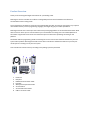
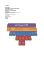
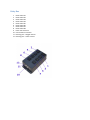
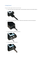
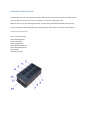
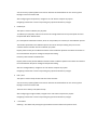
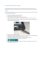
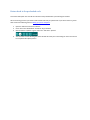
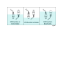
User Manual
V2.1.5
Copyright 2010 – Reef Angel
All Rights Reserved
The product and the information contained herein are subject to change without notice.
This manual may not, in whole or in part, be reproduced or transmitted in any form either electronically or mechanically, including
photocopying and recording, without the express written consent of Reef Angel.
Important Safety Instructions
PLEASE READ AND FOLLOW ALL SAFETY INSTRUCTIONS BEFORE PROCEDING
DANGER
Discontinue use if any signs of water are present in any electronic/electrical
device.
WARNING – To avoid injury to yourself and others, safety precautions should always be observed.
DANGER – Never attempt to service any electronic /electrical equipment before unplugging the device
from the outlet. Risk of electrical shock if care is not taken. Special care should always be taken when
operating any aquarium equipment. If the plug or receptacle gets wet, NEVER unplug it from the
outlet. Always use the fuse or circuit breaker that supplies power to the device. Disconnect it and then
examine for water presence.
•
•
•
If device shows any sign of abnormal appearance, discontinue use.
Never operate the device if plugs or cords are damaged, torn, ripped or malfunctioning.
A “drip loop” should be arranged and position your aquarium stand and tank to the side of the
power receptacle to avoid the device or power receptacle from getting wet. Please refer to
Figure 1 below.
Figure 1
Product Overview
Thank you for choosing Reef Angel Controller kit for your Reefing needs.
Reef Angel is the first controller kit to offer the reefing hobbyist full control of hardware and software to
accommodate all their reefing needs.
At your fingertips is the ability to create the most sophisticated controller you will ever need. With a very simple to
use interface and easy to learn programming language, Reef Angel will give you endless possibilities.
Reef Angel was built in the same open-source electronics prototyping platform as the world famous Arduino. What
does it mean? It means you can rest assured that your reef controller is working on the most stable platform on
the market. Programmers from all over the world have spent countless hours perfecting the coding on this
platform.
Not familiar with the programming world? Just looking for an all-in-one and out-of-the-box solution for your reef
system? Not a problem. Reef Angel Controller comes with its own built-in software that will leave you with your
mouth open as it's taking care of your reef system.
Your controller kit contents will vary according to the package you have purchased.
1.
2.
3.
4.
5.
6.
7.
8.
Head Unit
Relay Box
HDDB15 Communication Cable
PH Probe
Waterproof Temperature Probe
2x Float Switch
2x Float Switch Connectors
USB-TTL converter cable
Features
Arduino platform
ATMega328P microcontroller running at 16MHz
128x128 Color LCD screen
64K EEprom memory (2 banks of 32K)
Real time clock
Battery backup for clock settings
Analog thumb joystick with center select push-button
PH circuit
8 general I/Os with inverted gates
1-wire headers
Serial UART header
Power LED
Status LED
Controller Head Unit
1.
2.
3.
4.
5.
6.
7.
8.
ATO low Level
ATO high Level
PH probe connector
Temperature sensor connectors
Color LCD Screen
Thumb Joystick
Communication connector
Serial TTL connector
Relay Box
1.
2.
3.
4.
5.
6.
7.
8.
9.
10.
11.
12.
Outlet socket #1
Outlet socket #2
Outlet socket #3
Outlet socket #4
Outlet socket #5
Outlet socket #6
Outlet socket #7
Outlet socket #8
Power inlet connector
Communication connector
Dimming port – Daylight channel
Dimming port – Actinic channel
Dimming Ports
Communication Cable
Getting Started
Using your Reef Angel Controller for the first time
1.
Insert one end of the communication cable to the communication connector of the controller head unit.
2.
Insert the other end of the communication cable to the communication connector of the relay box.
3.
Plug the temperature probe to the head unit
4.
Plug the pH probe to the head unit
5.
6.
7.
8.
9.
Insert the power cord to the power inlet connector of the relay box.
Follow all steps and precautions and exercise caution when working with electronic devices near any
source of water.
Plug the power cord to the wall outlet.
You should now see the green power led on and the preloaded code already running on the LCD screen.
Congratulations. You have powered your Reef Angel Controller for the first time.
When you have your Reef Controller up and running, you can start using it immediately with the Reef Angel
Controller preloaded code or you can start hands-on with your controller to design and develop your own
customized code.
About the Preloaded Code
The Preloaded code is an out-of-the-box complete solution for the most common functions one would need to
control a reef tank. No need to connect to a computer. You can start using it right away.
When you first turn on your Reef Angel Controller, you will see the preloaded code already running for you.
To make a solution as simple as possible, pre-assigned functions were chosen for each port on the relay box.
Outlet Socket Assignment
Port 1: Auto top-off pump
Port 2: Moonlight lights
Port 3: Actinic lights
Port 4: Daylight lights
Port 5: Wavemaker pump 2
Port 6: Wavemaker pump 1
Port 7: Heater
Port 8: Return pump
Main Menu
In the Main Menu, you can change modes and configure the various settings for each function, such as Light
schedule, heater temperature, ATO Timeout etc.
Change of Mode and configuration is achieved by using the joystick on your Reef Angel Controller. To access the
Main Menu, simply press the joystick down.
You will see the menu options available on the screen.
1.
2.
3.
4.
5.
6.
7.
8.
Feeding
Water Change
Lights ->
Temps ->
Timeouts ->
Setup ->
Version
Exit
You can move through each menu option by moving the joystick up or down. To select the menu option, press the
joystick down. Menu options that have an arrow symbol “->” indicate that they have sub-menu options available.
1.
Feeding Mode
This is a special mode that can be used when you are feeding your livestock. It disables the Wavemaker ports
(Ports 5 and 6).
The duration of this mode is 15 minutes and a countdown is shown on the screen.
2.
Water Change Mode
This is a special mode that can be used when you are doing maintenance on your tank, such as a water
change. It disables the ATO, Wavemaker, Heater and Return ports (Ports 1, 5, 6, 7 and 8).
This mode does not have a preset duration and can only be terminated by pressing the joystick down.
3.
Lights ->
This menu option is used to setup your light schedule, the dimming port output level and also turn your lights
on/off for those occasions when you just want to temporarily show off your tank to your guests. It has the
following sub-menu options:
1.
Lights On
This option will turn on your Daylight and Actinic ports (Ports 3 and 4) and set the dimming ports to their
maximum configured level. Please refer to LED PWM for this setting.
After selecting this option, you are prompted with “Press to exit…” message. Simply press the joystick
down to return to the previous menu. This will not deactivate the “Lights On” mode.
2.
Lights Off
This option will turn off your Daylight and Actinic ports (Ports 3 and 4) that were turned on with the
“Lights On” menu option and set the dimming ports to zero.
After selecting this option, you are prompted with “Press to exit…” message. Simply press the joystick
down to return to the previous menu.
3.
Standard Lights
This option will let you setup your light schedule. These settings are for your Daylight port (Port 4). The
Actinic Port (Port 3) is offset by 30 minutes. The offset is for both ends of your lighting cycle. Actinic lights
will turn on 30 minutes before and turn off 30 minutes after your Daylight lights.
You can use the joystick up/down to increase or decrease the selected field. You can use the joystick
left/right to move to another field.
The times are in military time (24hrs format).
After configuring your light schedule, navigate to the “Ok” button and press the joystick.
Navigating to the button “Cancel” and pressing the joystick will discard any changes.
4.
LED PWM
This option will let you setup the maximum level of your dimming signal for each dimming port.
It is preconfigured to always start and end at zero.
The wave pattern that will be generated is a parabola, which simulates the rise and set of the sun.
You can use the joystick up/down to increase or decrease the selected field. You can use the joystick
left/right to move to another field.
After configuring your maximum level for each dimming signal, navigate to the “Ok” button and press the
joystick.
Navigating to the button “Cancel” and pressing the joystick will discard any changes.
5.
<- Prev Menu
Selecting <- Prev Menu and pressing the joystick down will return back to the previous menu.
4.
Temps ->
This menu option is used to setup the temperatures of your heater function. It has the following sub-menu
options:
1.
Heater
This option will let you setup the temperatures that you would like your heater to turn on and turn off.
You can use the joystick up/down to increase or decrease the selected field. You can use the joystick
left/right to move to another field.
The temperatures are shown without the decimal point. If you want for example to set the heater to turn
on at 77.0F and turn off at 77.9F, the values on the screen would be 770 and 779 respectively.
After configuring the temperatures, navigate to the “Ok” button and press the joystick.
Navigating to the button “Cancel” and pressing the joystick will discard any changes.
2.
Chiller
This option is not used on the preloaded code.
3.
Overheat Set
This option is used to setup the overheat temperature.
When an overheat temperature event occurs, both Daylight and Actinic ports (Ports 3 and 4) and the
heater (Port 7) will be turned off and the red LED status will light up.
These ports will not come back on by themselves to prevent the equipment from turning on and off
repeatedly and possibly causing some damage.
You must use the menu option “Overheat Clear” to return the controller into normal operation again.
You can use the joystick up/down to increase or decrease the selected field. You can use the joystick
left/right to move to another field.
The temperatures are shown without the decimal point. If you want for example to set the overheat
temperature to be 83.2F, the values on the screen would be 832.
After configuring the temperatures, navigate to the “Ok” button and press the joystick.
Navigating to the button “Cancel” and pressing the joystick will discard any changes.
4.
Overheat Clear
This option will return the controller into normal operation again after an overheat event.
After selecting this option, you are prompted with “Press to exit…” message. Simply press the joystick
down to return to the previous menu.
5.
<- Prev Menu
Selecting <- Prev Menu and pressing the joystick down will return back to the previous menu.
5.
Timeouts - >
1.
ATO Set
This option is used to setup the ATO timeout. Please refer to section “Assembling the float switch cables”
for more information on how the ATO function operates.
When an ATO timeout event occurs, the ATO port (Port 1) will be turned off and the red LED status will
light up.
These ports will not come back on by themselves to prevent the equipment from running dry or
overflowing and possibly causing some damage.
You must use the menu option “ATO Clear” to return the controller into normal operation again.
You can use the joystick up/down to increase or decrease the selected field. You can use the joystick
left/right to move to another field.
After configuring the temperatures, navigate to the “Ok” button and press the joystick.
Navigating to the button “Cancel” and pressing the joystick will discard any changes.
2.
ATO Clear
This option will return the controller into normal operation again after an ATO timeout event.
After selecting this option, you are prompted with “Press to exit…” message. Simply press the joystick
down to return to the previous menu.
3.
<- Prev Menu
Selecting <- Prev Menu and pressing the joystick down will return back to the previous menu.
6.
Setup ->
1.
Wavemaker
This option is used to setup the Wavemaker cycles.
You can use the joystick up/down to increase or decrease the selected field. You can use the joystick
left/right to move to another field.
After configuring the temperatures, navigate to the “Ok” button and press the joystick.
Navigating to the button “Cancel” and pressing the joystick will discard any changes.
2.
Calibrate pH
This option is used to calibrate your pH probe.
To calibrate your pH probe, make sure to remove the storage bottle from the tip of the probe and rinse
the probe with RO or distilled water.
pH 7.0 and pH 10.0 calibration solution, which are not provided, are necessary for the calibration process.
The numbers presented in this calibration process are not the actual pH reading. They are the raw
numbers that the controller will use to calibrate your probe.
Dip the probe into the pH 7.0 calibration solution and let it stabilize. Optional: write down the number in
the center between the pH 7.0 reading and the pH 10.0 reading.
Rinse the probe with RO or distilled water.
Dip the probe into the pH 10.0 calibration solution and let it stabilize. Optional: write down the number in
the center between the pH 7.0 reading and the pH 10.0 reading.
After the reading stabilizes, navigate to the “Ok” button and press the joystick.
Navigating to the button “Cancel” and pressing the joystick will discard any changes.
3.
Date / Time
This option is used to setup the date and time of the controller.
You can use the joystick up/down to increase or decrease the selected field. You can use the joystick
left/right to move to another field.
The times are in military time (24hrs format).
After configuring your light schedule, navigate to the “Ok” button and press the joystick.
Navigating to the button “Cancel” and pressing the joystick will discard any changes.
4.
<- Prev Menu
Selecting <- Prev Menu and pressing the joystick down will return back to the previous menu.
7.
Version
This option is used to view which libraries version the controller is running.
Simply press the joystick down to return to the previous menu.
8.
Exit
Selecting Exit and pressing the joystick down will return back to the main screen.
Setup your computer
Windows
1.
2.
3.
Download the latest version of the Reef Angel Installer at http://www.reefangel.com/download.aspx
Follow the step by step instructions of the installer.
It will take care of installing all the necessary drivers and software.
For more detailed information, please watch the installation videos here:
http://forum.reefangel.com/viewtopic.php?f=15&t=60
MacOSX
1.
2.
Download the latest version of the Reef Angel Disk Image at http://www.reefangel.com/download.aspx
After downloading the disk image (.dmg), it should be mounted automatically, but in case it is not, simply
double-click the file.
3.
Drag the Arduino folder to the Documents folder
4.
Drag the Arduino folder to the Applications folder
5.
Drag the Wifi Utility folder to the Applications folder
6.
You will also need to install the USB TTL cable drivers. Double-click the file
FTDIUSBSerialDriver_10_4_10_5_10_6 and follow the instructions on each step. A restart of your
computer will be necessary to finish the driver installation.
7. Connect the USB TTL Converter cable into any available USB port on your computer.
8. Start the Arduino IDE by double-clicking Arduino application
9. On the menu Tools > Board, make sure you have '''Reef Angel Controller w/ optiboot'''
10. On the menu Tools > Serial Port, make sure the selected serial port is something like '''/dev/tty.usbserial'''
Loading your Initial Memory Settings
The Reef Angel Controller stores several setting in a non-volatile type of memory, which means you can rest
assured that your settings will remain intact and won’t be lost in the case of power interruption or reboot of the
controller.
A newly acquired Reef Angel will not have any settings stored in the memory and you need to set them up before
you can start using any custom code.
1.
2.
3.
Make sure the Reef Angel Controller is powered up.
Connect the USB-TTL converter cable to your PC.
Connect the USB-TTL converter cable to your Reef Angel Controller.
Note: Make sure you connect the cable as the picture below. The black wire must be the right-most
position and the 2 left-most pins must be unconnected. Failure to do so can lead to damage to your Reef
Angel Controller head unit and/or cable.
4.
5.
Open the Arduino Environment software.
Depending on which controller you purchased, make sure you have “Reef Angel Controller w/optiboot” or
“Reef Angel Plus Controller” selected under the menu “Tools -> Board”.
Go to menu “File->Sketchbook->Example Codes” and select “InitialInternalMemory”
Click the button “Upload” or go to menu “File” and select “Upload”
6.
7.
8.
The controller will start blinking the status LED and will show your initial settings on the screen when it
has completed the upload process.
Loading your first code
Now that we have your Arduino IDE and your Reef Angel Controller configured and ready to be used, let's load
your first code into your Reef Angel Controller.
Every time you upload a code to your controller, the previous code is erased.
1.
2.
3.
Open the Arduino Environment software
Go to menu “File->Sketchbook->Example Codes” and select “Template”
Click the button “Upload” or go to menu “File” and select “Upload”
4.
The controller will start blinking the status LED and will show your initial settings on the screen when it
has completed the upload process.
You will see the standard graphical interface of the controller. With this example code, the controller will
not be actually activating any relays nor be doing anything else besides showing you the graphical
interface.
Note: If you see the message “No Internal Memory Found” on your screen, please refer to “Loading your
Initial Memory Settings” in this manual.
This is just a template code example to show you how to load codes to your controller. To return back to
the preloaded code, please visit “Return back to the preloaded code”
If you used the Reef Angel Installer to install and configure your computer, you will also have several
example codes you can upload to try out. To find them simply go to menu “File->Sketchbook->Example
codes” and you will see several example codes. You can also download them at
http://www.reefangel.com/Download.ashx
5.
6.
7.
Return back to the preloaded code
This tutorial will explain how to load the code that came preloaded with your Reef Angel Controller.
We are assuming you have your Arduino IDE installed and ready to upload code. If you haven't done so, please
take a look at the following tutorial "Setting up your PC computer".
1.
2.
3.
Open the Arduino Environment software
Go to menu “File->Sketchbook” and select “RA_Preloaded”
Click the button “Upload” or go to menu “File” and select “Upload”
4.
The controller will start blinking the status LED and will show your initial settings on the screen when it
has completed the upload process.
Creating your own code
The best and easiest way to create your own code is to use the Reef Angel Wizard.
With just a few clicks of your mouse, you will be able to generate your own custom code.
To start using the Reef Angel Wizard, please open Arduino and go to menu Tools->Reef Angel Wizard.
For more detailed information on how to use the Reef Angel Wizard, please visit
http://forum.reefangel.com/viewtopic.php?f=8&t=1297
Assembling the float switch cables
The float switches and connectors come disassembled, so you can extend the cables easily to accommodate your
own requirements.
For the purposes of demonstration how to assemble them, we are not going to be extending the cables.
Please follow these simple steps to get your cables assembled. These cables don't have any polarity, so you can
connect them together in whichever way you would like without worrying about polarity.
You can use shrink-wrap tubing or electrical tape (not provided) to isolate the junctions.
Step 1
Start with just 1 float switch and 1 connector.
Step 2
Strip about 3/4in of the end of each wire and insert the shrink wrap tubing.
Step 3
Twist the wires together.
Step 4
Apply heat to the shrink wrap tubing.
Step 5
Repeat steps 1 through 4 to the other pair of wires.
Step 6
You have completed the assembling of the ATO float switch.
Mounting the float switches
After assembling the float switches, you will need to mount them in your sump or display tank. Mounting brackets
are not provided.
The standard ATO function will require you to mount the switches in opposite direction and the operation works
according to Figure1.
Figure1