1
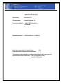
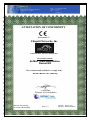
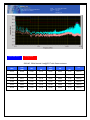
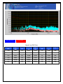
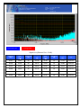
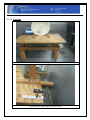
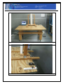
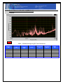
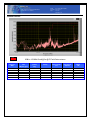
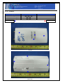
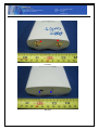
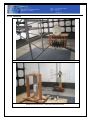
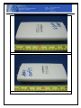
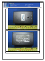
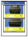
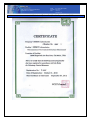
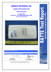
UBIQUITI NETWORKS, INC AIRMAX TDMA BASESTATION Model: Rocket M3 Dec 01st, 2011 Report No.: SL11102001-UBN-001(EMC) (This report supersedes: NONE) Modifications made to the product : None This Test Report is Issued Under the Authority of: David Zhang Compliance Engineer Leslie Bai Director of Certification This test report may be reproduced in full only. Title: To EMC Test Report of AirMax TDMA BaseStation EN 301 489-4 V1.4.1 (2009-05) Serial# SL11102001-UBN-001(EMC) Issue Date Dec 01st, 2011 Page 2 of 107 www.siemic.com CERTIFICATE OF TEST Date of Issue : Dec 01st, 2011 Company Name : Ubiquiti Networks, Inc Product Name/Model : AirMax TDMA BaseStation / Rocket M3 Stipulated Standard: (1) EN 301 489-4 V1.4.1 (2009-05) Equipment complied with the specification Equipment did not comply with the specification [X ] [ ] The submission documentation to a National Regulatory Body for type approval purposes shall consist of two parts; Part one: Application Form; Part two: Test Report; Title: To Serial# SL11102001-UBN-001(EMC) Issue Date Dec 01st, 2011 Page 3 of 107 www.siemic.com EMC Test Report of AirMax TDMA BaseStation EN 301 489-4 V1.4.1 (2009-05) ATTESTATION OF CONFORMITY Presented To: Ubiquiti Networks, Inc 91 E.Tasman Drive, San Jose, CA 95134 USA For Product/Model: AirMax TDMA BaseStation Rocket M3 Was evaluated and confirmed to comply with: EN 301 489-4 V1.4.1 (2009-05) Leslie Bai Director of Certification Reference Test Report No.: SL11102001-UBN-001(EMC) Page 1 of 1 Issue Date : Dec 01st, 2011 Test House : SIEMIC Laboratories Title: To EMC Test Report of AirMax TDMA BaseStation EN 301 489-4 V1.4.1 (2009-05) Serial# SL11102001-UBN-001(EMC) Issue Date Dec 01st, 2011 Page 4 of 107 www.siemic.com Laboratory Introduction ATION SIEMIC, headquartered in the heart of Silicon Valley, with superior facilities in US and Asia, is one of the leading independent testing and certification facilities providing customers with one-stop shop services for Compliance Testing and Global Certifications. In addition to testing and certification, SIEMIC provides initial design reviews and compliance management through out a project. Our extensive experience with China, Asia Pacific, North America, European, and international compliance requirements, assures the fastest, most cost effective way to attain regulatory compliance for the global markets. Accreditations for Conformity Assessment Country/Region Accreditation Body Scope USA Canada Taiwan Hong Kong Australia Korea Japan Mexico Europe FCC, A2LA IC, A2LA, NIST BSMI , NCC , NIST OFTA , NIST NATA, NIST KCC/RRA, NIST VCCI, JATE, TELEC, RFT NOM, COFETEL, Caniety A2LA, NIST EMC , RF/Wireless , Telecom , SAR EMC, RF/Wireless , Telecom , SAR EMC, RF, Telecom , Safety RF/Wireless ,Telecom EMC, RF, Telecom , Safety EMI, EMS, RF , Telecom, Safety , SAR EMI, RF/Wireless, Telecom Safety, EMC , RF/Wireless, Telecom EMC, RF, Telecom , Safety, SAR Accreditations for Product Certifications Country Accreditation Body Scope USA Canada Singapore EU Japan HongKong FCC TCB, NIST IC FCB , NIST iDA, NIST NB MIC (RCB 208) OFTA (US002) EMC , RF , Telecom EMC , RF , Telecom EMC , RF , Telecom EMC & R&TTE Directive RF , Telecom RF , Telecom Title: To EMC Test Report of AirMax TDMA BaseStation EN 301 489-4 V1.4.1 (2009-05) This page has been left blank intentionally. Serial# SL11102001-UBN-001(EMC) Issue Date Dec 01st, 2011 Page 5 of 107 www.siemic.com Title: To EMC Test Report of AirMax TDMA BaseStation EN 301 489-4 V1.4.1 (2009-05) Serial# SL11102001-UBN-001(EMC) Issue Date Dec 01st, 2011 Page 6 of 107 www.siemic.com CONTENTS 1 EXECUTIVE SUMMARY & EUT INFORMATION ................................................................................................................... 8 2 TECHNICAL DETAILS......................................................................................................................................................... 9 3 MODIFICATION ................................................................................................................................................................ 10 4 TEST SUMMARY .............................................................................................................................................................. 11 5 MEASUREMENTS, EXAMINATION AND DERIVED RESULTS ............................................................................................ 12 ANNEX A. TEST INSTRUMENT & METHOD ............................................................................................................................... 54 ANNEX B EUT PHOTOGRAPHS............................................................................................................................................... 66 ANNEX C. TEST SETUP AND SUPPORTING EQUIPMENT .......................................................................................................... 74 ANNEX D USER MANUAL, BLOCK & CIRCUIT DIAGRAM ......................................................................................................... 79 ANNEX E SIEMIC ACCREDITATION.......................................................................................................................................... 80 Title: To EMC Test Report of AirMax TDMA BaseStation EN 301 489-4 V1.4.1 (2009-05) This page has been left blank intentionally. Serial# SL11102001-UBN-001(EMC) Issue Date Dec 01st, 2011 Page 7 of 107 www.siemic.com Title: To EMC Test Report of AirMax TDMA BaseStation EN 301 489-4 V1.4.1 (2009-05) Serial# SL11102001-UBN-001(EMC) Issue Date Dec 01st, 2011 Page 8 of 107 www.siemic.com 1 Executive Summary & EUT information The purpose of this test program was to demonstrate compliance of the Ubiquiti Networks, Inc, AirMax TDMA BaseStation, and model: Rocket M3 against the current Stipulated Standards. The Rocket M3 have demonstrated compliance with the EN 301 489-4 V1.4.1 (2009-05), . EUT Information EUT Description : AirMax TDMA BaseStation The Rocket is a rugged, hi-power, very linear 2x2 MIMO radio with enhanced receiver performance. It features incredible range performance (50+km) and breakthrough speed (150+Mbps real TCPI/IP). The device was specifically designed for outdoor PtP bridging and PTMP AirMax base-station applications. Model No Serial No Input Power Classification Per Stipulated Test Standard : Rocket M3 : N/A : 24V, 1A POE Supply : Class A Emission Product Per EN 301 489 Title: To EMC Test Report of AirMax TDMA BaseStation EN 301 489-4 V1.4.1 (2009-05) Serial# SL11102001-UBN-001(EMC) Issue Date Dec 01st, 2011 Page 9 of 107 www.siemic.com 2 TECHNICAL DETAILS Purpose Compliance testing of AirMax TDMA BaseStation with stipulated standard Applicant / Client Ubiquiti Networks, Inc 91 E.Tasman Drive San Jose, CA 95134 USA Manufacturer Ubiquiti Networks, Inc 91 E.Tasman Drive San Jose, CA 95134 USA Laboratory performing the tests Test report reference number Date EUT received Standard applied Dates of test (from – to) No of Units: Equipment Category: Trade Name: Microprocessor (s) RF Operating Frequency (ies) Clock/Oscillator Frequency (ies) Rated Input Power Port/Connectors SIEMIC Laboratories SL11102001-UBN-001(EMC) Oct 21st 2011 See page 2 Oct 21st - Nov 30th 2011 #1 Fixed Radio Links Ubiquiti Networks, Inc unidentified 3,415 – 3,695MHz(TX/RX) / 5MHz Channel Separation & Bandwidth 3,420 – 3,690MHz(TX/RX) / 10MHz Channel Separation & Bandwidth 3,425 – 3,680MHz(TX/RX) / 15MHz Channel Separation & Bandwidth -24V, 1A POE Supply RJ45, POE Title: To Serial# SL11102001-UBN-001(EMC) Issue Date Dec 01st, 2011 Page 10 of 107 www.siemic.com EMC Test Report of AirMax TDMA BaseStation EN 301 489-4 V1.4.1 (2009-05) 3 MODIFICATION NONE Title: To Serial# SL11102001-UBN-001(EMC) Issue Date Dec 01st, 2011 Page 11 of 107 www.siemic.com EMC Test Report of AirMax TDMA BaseStation EN 301 489-4 V1.4.1 (2009-05) 4 TEST SUMMARY The product was tested in accordance with the following specifications. The Pass / Fail Criteria for the immunity tests were specified in Annex Ciii. All Testing has been performed according to below product classification: Class A Emission Product Per EN 301 489 Test Results Summary Emissions Test Standard EN 301 489-4 V1.4.1 (2009-05) Description Conducted Emission Radiated Spurious Emission Harmonic Current Emission Limit of Voltage Change, Fluctuation & Flicker Product Class See above See above N/A N/A Pass / Fail Pass Pass Pass Pass Description Criterion Pass / Fail Electrostatic Discharge Immunity B Pass A B B N/A A Pass Pass Pass N/A Pass Immunity Test Standard Radiated RF Immunity Electrical Fast Transient / Burst Immunity EN 301 489-4 V1.4.1 (2009-05) Voltage Surge Immunity Voltage Dip Immunity Conducted Disturbance Immunity PS: All Measurement Uncertainty is not taken into consideration for presented test data Title: To EMC Test Report of AirMax TDMA BaseStation EN 301 489-4 V1.4.1 (2009-05) Serial# SL11102001-UBN-001(EMC) Issue Date Dec 01st, 2011 Page 12 of 107 www.siemic.com 5 MEASUREMENTS, EXAMINATION AND DERIVED RESULTS 5.1 TEST RESULT 5.1.1 Conducted Emission Test Result Note: 1. 2. 3. 4. All possible modes of operation were investigated. Only the 6 worst case emissions measured, using the correct CISPR and Average detectors, are reported. All other emissions were relatively insignificant. A "-ve" margin indicates a PASS as it refers to the margin present below the limit line at the particular frequency. Conducted Emissions Measurement Uncertainty All test measurements carried out are traceable to national standards. The uncertainty of the measurement at a confidence level of approximately 95% (in the case where distributions are normal), with a coverage factor of 2, in the range 9kHz – 30MHz (Average & Quasi-peak) is ±3.86dB. Environmental Conditions Temperature 26oC Relative Humidity 62% Atmospheric Pressure 1010mbar Test date : Oct 21st - Nov 30th, 2011 Tested by : David Zhang Title: To Serial# SL11102001-UBN-001(EMC) Issue Date Dec 01st, 2011 Page 13 of 107 www.siemic.com EMC Test Report of AirMax TDMA BaseStation EN 301 489-4 V1.4.1 (2009-05) 5.1.1.1 Conducted Emission Test Result Quasi-Peak Limit Average Limit 230VAC, 50Hz Phase Line @ EUT with Dish antenna Frequency (MHz) QP Value (dBV) Class A Limit (dB) (dB) Avg Value (dBV) Class A Limit (dB) 23.13 61.93 73.00 -11.07 58.75 60.00 -1.25 Phase 23.06 57.65 73.00 -15.35 54.99 60.00 -5.01 Phase 22.88 60.05 73.00 -12.95 57.37 60.00 -2.63 Phase 23.43 56.55 73.00 -16.45 54.08 60.00 -5.92 Phase 24.35 59.23 73.00 -13.77 56.98 60.00 -3.02 Phase 22.58 59.11 73.00 -13.89 56.27 60.00 -3.73 Phase Margin Margin Line (dB) Title: To Serial# SL11102001-UBN-001(EMC) Issue Date Dec 01st, 2011 Page 14 of 107 www.siemic.com EMC Test Report of AirMax TDMA BaseStation EN 301 489-4 V1.4.1 (2009-05) Quasi-Peak Limit Average Limit 230VAC, 50Hz Neutral Line@ EUT with Dish antenna Frequency (MHz) QP Value (dBV) Class A Limit (dB) (dB) Avg Value (dBV) Class A Limit (dB) 23.13 61.49 73.00 -11.51 58.05 60.00 -1.95 Neutral 23.06 57.02 73.00 -15.98 55.90 60.00 -4.10 Neutral 22.46 59.71 73.00 -13.29 58.55 60.00 -1.45 Neutral 21.66 60.31 73.00 -12.69 59.06 60.00 -0.94 Neutral 24.35 59.03 73.00 -13.97 58.18 60.00 -1.82 Neutral 20.26 58.01 73.00 -14.99 56.66 60.00 -3.34 Neutral Margin Margin Line (dB) Title: To Serial# SL11102001-UBN-001(EMC) Issue Date Dec 01st, 2011 Page 15 of 107 www.siemic.com EMC Test Report of AirMax TDMA BaseStation EN 301 489-4 V1.4.1 (2009-05) Quasi-Peak Limit Average Limit 230VAC, 50Hz Phase Line@ EUT with Sector antenna Frequency (MHz) QP Value (dBV) Class A Limit (dB) (dB) Avg Value (dBV) Class A Limit (dB) 24.35 59.71 73.00 -13.29 57.39 60.00 -2.61 Phase 23.13 61.73 73.00 -11.27 58.25 60.00 -1.75 Phase 24.53 59.02 73.00 -13.98 56.73 60.00 -3.27 Phase 24.04 59.09 73.00 -13.91 56.67 60.00 -3.33 Phase 24.90 54.49 73.00 -18.51 52.15 60.00 -7.85 Phase 24.72 56.87 73.00 -16.13 54.55 60.00 -5.45 Phase Margin Margin Line (dB) Title: To Serial# SL11102001-UBN-001(EMC) Issue Date Dec 01st, 2011 Page 16 of 107 www.siemic.com EMC Test Report of AirMax TDMA BaseStation EN 301 489-4 V1.4.1 (2009-05) Quasi-Peak Limit Average Limit 230VAC, 50Hz Neutral Line@ EUT with Sector antenna Frequency (MHz) QP Value (dBV) Class A Limit (dB) (dB) Avg Value (dBV) Class A Limit (dB) 23.13 61.49 73.00 -11.51 58.05 60.00 -1.95 Neutral 23.06 57.02 73.00 -15.98 55.90 60.00 -4.10 Neutral 22.46 59.71 73.00 -13.29 58.55 60.00 -1.45 Neutral 21.66 60.31 73.00 -12.69 59.06 60.00 -0.94 Neutral 24.35 59.03 73.00 -13.97 58.18 60.00 -1.82 Neutral 20.26 58.01 73.00 -14.99 56.66 60.00 -3.34 Neutral Margin Margin Line (dB) Title: To Serial# SL11102001-UBN-001(EMC) Issue Date Dec 01st, 2011 Page 17 of 107 www.siemic.com EMC Test Report of AirMax TDMA BaseStation EN 301 489-4 V1.4.1 (2009-05) Quasi-Peak Limit Average Limit Signal Line (POE Port) Frequency (MHz) QP Value (dBV) Class A Limit (dB) (dB) Avg Value (dBV) Class A Limit (dB) 1.28 44.83 87 -42.17 42.50 74 -31.50 POE 1.11 41.12 87 -45.88 25.59 74 -48.41 POE 0.77 43.32 87 -43.68 41.98 74 -32.02 POE 1.30 38.30 87 -48.70 27.85 74 -46.15 POE 1.17 37.78 87 -49.22 31.05 74 -42.95 POE 1.41 38.97 87 -48.03 26.45 74 -47.55 POE Margin Margin Line (dB) Title: To Serial# SL11102001-UBN-001(EMC) Issue Date Dec 01st, 2011 Page 18 of 107 www.siemic.com EMC Test Report of AirMax TDMA BaseStation EN 301 489-4 V1.4.1 (2009-05) Quasi-Peak Limit Average Limit Signal Line (Ethernet Port – RJ45) Frequency (MHz) QP Value (dBV) Class A Limit (dB) (dB) Avg Value (dBV) Class A Limit (dB) 26.61 49.82 87 -37.18 46.48 74 -27.52 Ethernet 26.48 47.29 87 -39.71 44.04 74 -29.96 Ethernet 29.23 47.43 87 -39.57 44.27 74 -29.73 Ethernet 28.68 49.26 87 -37.74 45.96 74 -28.04 Ethernet 27.16 47.88 87 -39.12 44.60 74 -29.40 Ethernet 27.34 46.45 87 -40.55 43.11 74 -30.89 Ethernet Margin Margin Line (dB) Title: To EMC Test Report of AirMax TDMA BaseStation EN 301 489-4 V1.4.1 (2009-05) Serial# SL11102001-UBN-001(EMC) Issue Date Dec 01st, 2011 Page 19 of 107 www.siemic.com 5.1.1.2 Test Set up Conducted Emission Test Setup @ EUT with Dish antenna Conducted Emission Test Setup @ EUT with Dish antenna Title: To EMC Test Report of AirMax TDMA BaseStation EN 301 489-4 V1.4.1 (2009-05) Serial# SL11102001-UBN-001(EMC) Issue Date Dec 01st, 2011 Page 20 of 107 www.siemic.com Conducted Emission Test Setup @ EUT with Sector antenna Conducted Emission Test Setup @ EUT with Sector antenna Title: To EMC Test Report of AirMax TDMA BaseStation EN 301 489-4 V1.4.1 (2009-05) Serial# SL11102001-UBN-001(EMC) Issue Date Dec 01st, 2011 Page 21 of 107 www.siemic.com 5.1.2 Radiated Spurious Emission Test Results Note: 1. 2. 3. 4. All possible modes of operation were investigated. Only the 6 worst case emissions measured, using the correct CISPR detectors, are reported. All other emissions were relatively insignificant. A "-ve" margin indicates a PASS as it refers to the margin present below the limit line at the particular frequency. Radiated Emissions Measurement Uncertainty All test measurements carried out are traceable to national standards. The uncertainty of the measurement at a confidence level of approximately 95% (in the case where distributions are normal), with a coverage factor of 2, in the range 30MHz – 1GHz (QP only @ 3m & 10m) is ±6.0dB (for EUTs < 0.5m X 0.5m X 0.5m). Environmental Conditions Temperature 25oC Relative Humidity 62% Atmospheric Pressure 1011mbar Test date : Oct 21st - Nov 30th, 2011 Tested by : David Zhang Title: To Serial# SL11102001-UBN-001(EMC) Issue Date Dec 01st, 2011 Page 22 of 107 www.siemic.com EMC Test Report of AirMax TDMA BaseStation EN 301 489-4 V1.4.1 (2009-05) 5.1.2.1 Radiated Emission Test Result (7GHz Unit) Radiated Emissions Limit 30MHz ~1000MHz Result @ 3m @ EUT with Dish antenna Frequency (MHz) Corrected QuasiPeak (dBµV/m) @ 3m Turntable position (deg) Polarity Antenna height (cm) Class A Limit (dBµV/m) Margin (dB) 196.05 779.99 212.67 148.78 822.74 183.80 9.73 33.39 13.44 8.60 20.97 18.29 23.00 125.00 33.00 206.00 359.00 129.00 V V V V V V 143.00 111.00 143.00 193.00 187.00 111.00 40.00 47.00 40.00 40.00 47.00 40.00 -30.27 -13.61 -26.56 -31.40 -26.03 -21.71 Title: To Serial# SL11102001-UBN-001(EMC) Issue Date Dec 01st, 2011 Page 23 of 107 www.siemic.com EMC Test Report of AirMax TDMA BaseStation EN 301 489-4 V1.4.1 (2009-05) Radiated Emissions Limit 30MHz ~1000MHz Result @ 3m @ EUT with Sector antenna Frequency (MHz) Corrected QuasiPeak (dBµV/m) @ 3m Turntable position (deg) Polarity Antenna height (cm) Class A Limit (dBµV/m) Margin (dB) 194.99 780.00 832.33 194.56 847.99 183.02 12.56 42.65 20.79 22.74 20.81 9.16 334.00 197.00 172.00 19.00 270.00 140.00 V H H V H H 277.00 115.00 237.00 107.00 307.00 142.00 40.00 47.00 47.00 40.00 47.00 40.00 -27.44 -4.35 -26.21 -17.26 -26.19 -30.84 Title: To Serial# SL11102001-UBN-001(EMC) Issue Date Dec 01st, 2011 Page 24 of 107 www.siemic.com EMC Test Report of AirMax TDMA BaseStation EN 301 489-4 V1.4.1 (2009-05) Radiated Emissions (Above 1GHz) Above 1GHz Test Result Result @ 3m @ EUT with Dish antenna Frequency (GHz) Final FS @ 3m (dBuV) Direction (degree) Height (m) Polarity (H/V) Antenna Loss (dB) Cable Loss (dB) Amplifier (dB) Class B Limit @ 3m (dBuV) Delta (dB) Detector (pk/avg) 1.062 1.062 2.729 2.729 5.090 5.090 5.639 4.659 39.60 25.58 39.97 27.10 43.08 30.55 43.30 30.51 0 0 0 0 4 4 4 4 1.20 1.20 1.00 1.00 1.40 1.40 1.20 1.20 V V V V H H V V 24.80 24.80 28.80 28.80 32.90 32.90 33.40 33.40 1.82 1.82 2.72 2.72 4.32 4.32 4.56 4.56 31.99 31.99 32.08 32.08 32.55 32.55 32.48 32.48 76 56 76 56 80 60 80 60 -36.40 -30.42 -36.03 -28.90 -36.92 -29.45 -36.70 -29.49 Peak Ave Peak Ave Peak Ave Peak Ave Above 1GHz Test Result @ 3m @ EUT with Sector antenna Frequency (GHz) Final FS @ 3m (dBuV) Direction (degree) Height (m) Polarity (H/V) Antenna Loss (dB) Cable Loss (dB) Amplifier (dB) Class B Limit @ 3m (dBuV) Delta (dB) Detector (pk/avg) 1.048 1.048 4.659 4.659 2.543 2.543 4.659 4.659 38.00 30.68 45.01 30.84 38.49 27.00 43.33 27.01 160 160 155 155 270 270 200 300 1.0 1.0 1.5 1.5 1.0 1.0 2.0 1.0 H H H H V V V V 24.8 24.8 32.2 32.2 28.8 28.8 32.2 32.2 1.82 1.82 4.13 4.13 2.72 2.72 4.13 4.13 31.99 31.99 32.49 32.49 32.08 32.08 32.49 32.49 76 56 80 60 76 56 80 60 -38.00 -25.32 -34.99 -29.16 -37.51 -29.00 -36.67 -32.99 Peak Ave Peak Ave Peak Ave Peak Ave Title: To EMC Test Report of AirMax TDMA BaseStation EN 301 489-4 V1.4.1 (2009-05) Serial# SL11102001-UBN-001(EMC) Issue Date Dec 01st, 2011 Page 25 of 107 www.siemic.com Radiated Emission Test Setup (30MHz – 1GHz) @ EUT with Dish antenna –Front Radiated Emission Test Setup (30MHz – 1GHz) @ EUT with Dish antenna -Rear Title: To EMC Test Report of AirMax TDMA BaseStation EN 301 489-4 V1.4.1 (2009-05) Serial# SL11102001-UBN-001(EMC) Issue Date Dec 01st, 2011 Page 26 of 107 www.siemic.com Radiated Emission Test Setup (30MHz – 1GHz) @ EUT with Sector antenna –Front Radiated Emission Test Setup (30MHz – 1GHz) @ EUT with Sector antenna -Rear Title: To EMC Test Report of AirMax TDMA BaseStation EN 301 489-4 V1.4.1 (2009-05) Serial# SL11102001-UBN-001(EMC) Issue Date Dec 01st, 2011 Page 27 of 107 www.siemic.com Radiated Emission Test Setup (>1GHz) @ EUT with Dish antenna –Front Radiated Emission Test Setup (>1GHz) @ EUT with Sector antenna -Rear Title: To EMC Test Report of AirMax TDMA BaseStation EN 301 489-4 V1.4.1 (2009-05) Serial# SL11102001-UBN-001(EMC) Issue Date Dec 01st, 2011 Page 28 of 107 www.siemic.com Radiated Emission Test Setup (>1GHz) @ EUT with Sector antenna –Front Radiated Emission Test Setup (>1GHz) @ EUT with Sector antenna -Rear Title: To 5.1.3 Serial# SL11102001-UBN-001(EMC) Issue Date Dec 01st, 2011 Page 29 of 107 www.siemic.com EMC Test Report of AirMax TDMA BaseStation EN 301 489-4 V1.4.1 (2009-05) Current Harmonic Emission Results N/A Title: To 5.1.4 EMC Test Report of AirMax TDMA BaseStation EN 301 489-4 V1.4.1 (2009-05) Voltage Fluctuation and Flicker Results Serial# SL11102001-UBN-001(EMC) Issue Date Dec 01st, 2011 Page 30 of 107 www.siemic.com Title: To EMC Test Report of AirMax TDMA BaseStation EN 301 489-4 V1.4.1 (2009-05) Serial# SL11102001-UBN-001(EMC) Issue Date Dec 01st, 2011 Page 31 of 107 www.siemic.com Flicker Test Setup (>1GHz) @ EUT with Dish antenna –Front Title: To 5.1.5 EMC Test Report of AirMax TDMA BaseStation EN 301 489-4 V1.4.1 (2009-05) Serial# SL11102001-UBN-001(EMC) Issue Date Dec 01st, 2011 Page 32 of 107 www.siemic.com Electrostatic Discharge Immunity Results Notes 1. 2. 3. 4. 5. 6 Please refer to the Pass/Fail criteria to interpret the results. Environmental Conditions Temperature 26oC Relative Humidity 60% Atmospheric Pressure 1019mbar Human Body Model Storage Capacitor 150pF Discharge Resistor 330 No. of Discharges / Point, Level & Polarity 10 air discharges Discharge Details 25 contact discharges Discharge Interval 1 second Measurement Uncertainty All test measurements carried out are traceable to national standards. The uncertainty of the measurement at a confidence level of approximately 95% (in the case where distributions are normal), with a coverage factor of 2, in the range 2kV, 4kV, 8kV, is 7.12%. Test date : Oct 21st - Nov 30th, 2011 Tested by : David Zhang *the performance criteria for transient phenomena shall apply Title: To Serial# SL11102001-UBN-001(EMC) Issue Date Dec 01st, 2011 Page 33 of 107 www.siemic.com EMC Test Report of AirMax TDMA BaseStation EN 301 489-4 V1.4.1 (2009-05) 5.1.5.1 Test Result Discharge Type Air Discharges Direct Contact Discharges Indirect Contact Discharges Test Severity Level 2kV, 4kV, 8kV 2kV, 4kV 2kV, 4kV Results Pass Pass Pass Contact Charges Air Charges Top View Bottom View Title: To Serial# SL11102001-UBN-001(EMC) Issue Date Dec 01st, 2011 Page 34 of 107 www.siemic.com EMC Test Report of AirMax TDMA BaseStation EN 301 489-4 V1.4.1 (2009-05) Front View Rear View Title: To EMC Test Report of AirMax TDMA BaseStation EN 301 489-4 V1.4.1 (2009-05) Serial# SL11102001-UBN-001(EMC) Issue Date Dec 01st, 2011 Page 35 of 107 www.siemic.com 5.1.5.2 Test Setup ESD Front View @ EUT with Dish antenna - Front ESD Back View@ EUT with Dish antenna - Rear Title: To EMC Test Report of AirMax TDMA BaseStation EN 301 489-4 V1.4.1 (2009-05) Serial# SL11102001-UBN-001(EMC) Issue Date Dec 01st, 2011 Page 36 of 107 www.siemic.com ESD Front View @ EUT with Sector antenna - Front ESD Back View @ EUT with Sector antenna - Rear Title: To 5.1.6 Serial# SL11102001-UBN-001(EMC) Issue Date Dec 01st, 2011 Page 37 of 107 www.siemic.com EMC Test Report of AirMax TDMA BaseStation EN 301 489-4 V1.4.1 (2009-05) RF Radiated Immunity Results Notes 1. 2. 3. Please refer to the Pass/Fail criteria to interpret the results. Environmental Conditions Temperature Relative Humidity Atmospheric Pressure Radiated Immunity Details Frequency Step Sweep Rate 25oC 60% 1015mbar 1% of fundamental 1.5 X 10- decades/s 4. The test was carried out on one surface. The surface selected to face the source of the interference signal is the one anticipated to be the most susceptible. 5. Measurement Uncertainty All test measurements carried out are traceable to national standards. The uncertainty of the measurement at a confidence level of approximately 95% (in the case where distributions are normal), with a coverage factor of 2, in the range from 80MHz-1GHz & 1.4~2.0GHz, test level ranges from 3V/m to 10V/m, is 0.74V/m. 6 Test date : Oct 21st - Nov 30th, 2011 Tested by : David Zhang *the performance criteria for continuous phenomena shall apply 5.1.6.1 Test Result Sides Tested Front (H) Front (V) Right (H) Right (V) Left (H) Left (V) Back (H) Back (V) Frequency Range 80 MHz – 1 GHz, 1.4 GHz - 2.7 GHz 80 MHz – 1 GHz, 1.4 GHz - 2.7 GHz 80 MHz – 1 GHz, 1.4 GHz - 2.7 GHz 80 MHz – 1 GHz, 1.4 GHz - 2.7 GHz 80 MHz – 1 GHz, 1.4 GHz - 2.7 GHz 80 MHz – 1 GHz, 1.4 GHz - 2.7 GHz 80 MHz – 1 GHz, 1.4 GHz - 2.7 GHz 80 MHz – 1 GHz, 1.4 GHz - 2.7 GHz Test Severity Level Result 10V/m, 80% AM (1kHz) Pass 10V/m, 80% AM (1kHz) Pass 10V/m, 80% AM (1kHz) Pass 10V/m, 80% AM (1kHz) Pass 10V/m, 80% AM (1kHz) Pass 10V/m, 80% AM (1kHz) Pass 10V/m, 80% AM (1kHz) Pass 10V/m, 80% AM (1kHz) Pass Title: To EMC Test Report of AirMax TDMA BaseStation EN 301 489-4 V1.4.1 (2009-05) Serial# SL11102001-UBN-001(EMC) Issue Date Dec 01st, 2011 Page 38 of 107 www.siemic.com 5.1.6.2 Test Set up Radiated Immunity Test Setup ( <1GHz) @ EUT with Dish antenna Radiated Immunity Test Setup ( >1GHz) @ EUT with Sector antenna Title: To EMC Test Report of AirMax TDMA BaseStation EN 301 489-4 V1.4.1 (2009-05) Serial# SL11102001-UBN-001(EMC) Issue Date Dec 01st, 2011 Page 39 of 107 www.siemic.com Radiated Immunity Test Setup ( <1GHz) @ EUT with Dish antenna Radiated Immunity Test Setup ( >1GHz) @ EUT with Sector antenna Title: To 5.1.7 EMC Test Report of AirMax TDMA BaseStation EN 301 489-4 V1.4.1 (2009-05) Serial# SL11102001-UBN-001(EMC) Issue Date Dec 01st, 2011 Page 40 of 107 www.siemic.com Electrical Fast Transient/Burst Immunity Results Notes 1. 2. 3. 4. 5 Please refer to the Pass/Fail criteria to interpret the results. Environmental Conditions Temperature 26oC Relative Humidity 60% Atmospheric Pressure 1019mbar EFT/B Test Details Test Duration / Level & Polarity 1 minute Measurement Uncertainty All test measurements carried out are traceable to national standards. The uncertainty of the measurement at a confidence level of approximately 95% (in the case where distributions are normal), with a coverage factor of 2, test level ranges from ±0.5kV to ±1kV 10V/m, is 1.2%. Test date : Oct 21st - Nov 30th, 2011 Tested by : David Zhang *the performance criteria for transient phenomena shall apply Title: To EMC Test Report of AirMax TDMA BaseStation EN 301 489-4 V1.4.1 (2009-05) Serial# SL11102001-UBN-001(EMC) Issue Date Dec 01st, 2011 Page 41 of 107 www.siemic.com 5.1.7.1 Test Result No. of Test Voltage Frequency Output: Line Coupling (MAINS) Results DC POWER INPUT PORT 1 - 500V 5.0kHz L1 Pass 2 +500V 5.0kHz L1 Pass 3 - 500V 5.0kHz L2 Pass 4 +500V 5.0kHz L2 Pass 5 - 500V 5.0kHz PE N/A 6 +500V 5.0kHz PE N/A 7 - 1000V 5.0kHz L1 Pass 8 +1000V 5.0kHz L1 Pass 9 - 1000V 5.0kHz L2 Pass 10 +1000V 5.0kHz L2 Pass 11 - 1000V 5.0kHz PE N/A 12 +1000V 5.0kHz PE N/A CONTROL & SIGNAL LINES 1 - 250V 5.0kHz User Ethernet Pass 2 +250V 5.0kHz User Ethernet Pass 3 - 500V 5.0kHz User Ethernet Pass 4 +500V 5.0kHz User Ethernet Pass 5 - 250V 5.0kHz PoE Cable Pass 6 +250V 5.0kHz PoE Cable Pass 7 - 500V 5.0kHz PoE Cable Pass 8 +500V 5.0kHz PoE Cable Pass Remarks: Degradation of performance of the EUT occurred when interference voltage was -500V on signal Cable, but they recovered after the testing, so the EUT meets the IEC 61000-4-4 test requirements. Title: To EMC Test Report of AirMax TDMA BaseStation EN 301 489-4 V1.4.1 (2009-05) Serial# SL11102001-UBN-001(EMC) Issue Date Dec 01st, 2011 Page 42 of 107 www.siemic.com 5.1.7.2 Test Setup Photo EFT Test Setup AC Line @ EUT with Dish antenna EFT Test Setup Signal Line @ EUT with Dish antenna Title: To EMC Test Report of AirMax TDMA BaseStation EN 301 489-4 V1.4.1 (2009-05) Serial# SL11102001-UBN-001(EMC) Issue Date Dec 01st, 2011 Page 43 of 107 www.siemic.com EFT Test Setup AC Line @ EUT with Sector antenna EFT Test Setup Signal Line @ EUT with Sector antenna Title: To 5.1.8 EMC Test Report of AirMax TDMA BaseStation EN 301 489-4 V1.4.1 (2009-05) Serial# SL11102001-UBN-001(EMC) Issue Date Dec 01st, 2011 Page 44 of 107 www.siemic.com Surge Immunity Results Note: 1. 2. 3. 4 Please refer to the Pass/Fail criteria to interpret the results. Environmental Conditions Temperature Relative Humidity Atmospheric Pressure Surges Test Details Repetition Rate Open-Circuit Voltage Waveform Short-Circuit Current Waveform Phase Angels Test date : Oct 21st - Nov 30th, 2011 Tested by : David Zhang *the performance criteria for continuous phenomena shall apply 25oC 60% 1005mbar At least 1 per minute 1.2/50 µs 8/20 µs 0º, 90º, 180º and 270º Title: To Serial# SL11102001-UBN-001(EMC) Issue Date Dec 01st, 2011 Page 45 of 107 www.siemic.com EMC Test Report of AirMax TDMA BaseStation EN 301 489-4 V1.4.1 (2009-05) 5.1.8.1 Test Result No. of Test Waveform Voltage Output: Line Coupling (MAINS) Phase Ref. Phase Angle Results DC POWER INPUT PORT 1 2 Ohm -1000V L1/L2 L1 0 degree N/A 2 2 Ohm -1000V L1/L2 L1 90 degree N/A 3 2 Ohm -1000V L1/L2 L1 270 degree N/A 4 2 Ohm +1000V L1/L2 L1 0 degree N/A 5 2 Ohm +1000V L1/L2 L1 90 degree N/A 6 2 Ohm +1000V L1/L2 L1 270 degree N/A 7 12 Ohm -2000V L1/PE L1 0 degree N/A 8 12 Ohm -2000V L1/PE L1 90 degree N/A 9 12 Ohm -2000V L1/PE L1 270 degree N/A 10 12 Ohm +2000V L1/PE L1 0 degree N/A 11 12 Ohm +2000V L1/PE L1 90 degree N/A 12 12 Ohm +2000V L1/PE L1 270 degree N/A 13 12 Ohm -2000V L2/PE L1 0 degree N/A 14 12 Ohm -2000V L2/PE L1 90 degree N/A 15 12 Ohm -2000V L2/PE L1 270 degree N/A 16 12 Ohm +2000V L2/PE L1 0 degree N/A 17 12 Ohm +2000V L2/PE L1 90 degree N/A 18 12 Ohm +2000V L2/PE L1 270 degree N/A CONTROL & SIGNAL LINES Signal Lines ±0.5kV Pass Title: To EMC Test Report of AirMax TDMA BaseStation EN 301 489-4 V1.4.1 (2009-05) Serial# SL11102001-UBN-001(EMC) Issue Date Dec 01st, 2011 Page 46 of 107 www.siemic.com 5.1.8.2 Test Setup Photo Surge Test Setup Front @ EUT with Dish antenna Surge Test Setup Rear @ EUT with Dish antenna Title: To EMC Test Report of AirMax TDMA BaseStation EN 301 489-4 V1.4.1 (2009-05) Serial# SL11102001-UBN-001(EMC) Issue Date Dec 01st, 2011 Page 47 of 107 www.siemic.com Surge Test Setup Front@ EUT with Sector antenna Surge Test Setup Rear @ EUT with Sector antenna Title: To 5.1.9 Serial# SL11102001-UBN-001(EMC) Issue Date Dec 01st, 2011 Page 48 of 107 www.siemic.com EMC Test Report of AirMax TDMA BaseStation EN 301 489-4 V1.4.1 (2009-05) Conducted Disturbance Immunity Results Note: 1. 2. Please refer to the Pass/Fail criteria to interpret the results. Environmental Conditions Temperature Relative Humidity Atmospheric Pressure Conducted Immunity Details Frequency Step 3. Sweep Rate 4. 5 25oC 61% 1029mbar 50kHz in the range 150kHz to 5MHz, 1% frequency increment of the momentary frequency in the range 5MHz to 80MHz 1.5 X 10- decades/s Measurement Uncertainty All test measurements carried out are traceable to national standards. The uncertainty of the measurement at a confidence level of approximately 95% (in the case where distributions are normal), with a coverage factor of 2, test level 3Vrms and 10Vrms, frequency raging from 150kHz to 80MHz, is ±1.60dB. Test date : Oct 21st - Nov 30th, 2011 Tested by : David Zhang *the performance criteria for continuous phenomena shall apply 5.1.9.1 Test Result Cable Frequency Range Test Severity Level Result AC power port Ethernet Port PoE Cable 150kHz - 80MHz 150kHz - 80MHz 150kHz - 80MHz 10Vrms, 80% AM (1kHz) 10Vrms, 80% AM (1kHz) 10Vrms, 80% AM (1kHz) Pass Pass Pass Remarks: No degradation of performance of the equipment under test with occurred during testing Title: To EMC Test Report of AirMax TDMA BaseStation EN 301 489-4 V1.4.1 (2009-05) Serial# SL11102001-UBN-001(EMC) Issue Date Dec 01st, 2011 Page 49 of 107 www.siemic.com 5.1.9.2 Test Set up Conducted Immunity Test Setup @ EUT with Dish antenna – AC Power Line Conducted Immunity Test Setup@ EUT with Dish antenna – Signal Cable Title: To EMC Test Report of AirMax TDMA BaseStation EN 301 489-4 V1.4.1 (2009-05) Serial# SL11102001-UBN-001(EMC) Issue Date Dec 01st, 2011 Page 50 of 107 www.siemic.com Conducted Immunity Test Setup@ EUT with Sector antenna – AC Line Conducted Immunity Test Setup @ EUT with Sector antenna – Signal Cable Title: To Serial# SL11102001-UBN-001(EMC) Issue Date Dec 01st, 2011 Page 51 of 107 www.siemic.com EMC Test Report of AirMax TDMA BaseStation EN 301 489-4 V1.4.1 (2009-05) 5.1.10 Voltage Dips And Interruption Immunity Results Note: 1. 2. Please refer to the Pass/Fail criteria to interpret the results. Environmental Conditions Temperature 25ºC Relative Humidity 50.5% Atmospheric Pressure 1015mbar Test Date : Oct 21st - Nov 30th, 2011 Tested By : David Zhang 3 *the performance criteria B shall apply for 30%/10ms & 60%/100ms. Otherwise, Performance criteria C shall apply. Verdict of this test considered as PASS. No. of Test 1 2 3 4 5 6 Test Level Phase Angle Duration Value Duration Test Results 70% Dip 80% Dip 40% Dip 0% Short 0% Open 70% Dip 80% Dip 40% Dip 0% Short 0% Open 40% Dip 70% Dip 80% Dip 0% Short 0% Open 40% Dip 70% Dip 80% Dip 0% Short 0% Open 0% Short 80% Dip 70% Dip 40% Dip 0% Open 80% Dip 70% Dip 40% Dip 0% Short 0% Open 0 degree 0 degree 0 degree 0 degree 0 degree 180 degree 180 degree 180 degree 180 degree 180 degree 0 degree 0 degree 0 degree 0 degree 0 degree 0 degree 0 degree 0 degree 0 degree 0 degree 0 degree 0 degree 0 degree 0 degree 0 degree 0 degree 0 degree 0 degree 0 degree 0 degree 0.50 0.50 0.50 0.50 0.50 0.50 0.50 0.50 0.50 0.50 5.00 5.00 5.00 5.00 5.00 50.00 50.00 50.00 50.00 50.00 250.00 250.00 250.00 250.00 250.00 250.00 250.00 250.00 250.00 250.00 Cycle Cycle Cycle Cycle Cycle Cycle Cycle Cycle Cycle Cycle Cycle Cycle Cycle Cycle Cycle Cycle Cycle Cycle Cycle Cycle Cycle Cycle Cycle Cycle Cycle Cycle Cycle Cycle Cycle Cycle 3 3 3 3 3 3 3 3 3 3 3 3 3 3 3 3 3 3 3 3 3 3 3 3 3 3 3 3 3 3 Pass Pass Pass Pass Pass Pass Pass Pass Pass Pass Pass Pass Pass Pass Pass Pass Pass Pass Pass Pass Pass Pass Pass Pass Pass Pass Pass Pass Pass Pass Title: To EMC Test Report of AirMax TDMA BaseStation EN 301 489-4 V1.4.1 (2009-05) Serial# SL11102001-UBN-001(EMC) Issue Date Dec 01st, 2011 Page 52 of 107 www.siemic.com Dips Test Setup @ EUT with Dish antenna - Front Surge Test Setup @ EUT with Dish antenna - Rear Title: To EMC Test Report of AirMax TDMA BaseStation EN 301 489-4 V1.4.1 (2009-05) Serial# SL11102001-UBN-001(EMC) Issue Date Dec 01st, 2011 Page 53 of 107 www.siemic.com Surge Test Setup @ EUT with Sector antenna - Front Surge Test Setup @ EUT with Sector antenna - Rear Title: To Serial# SL11102001-UBN-001(EMC) Issue Date Dec 01st, 2011 Page 54 of 107 www.siemic.com EMC Test Report of AirMax TDMA BaseStation EN 301 489-4 V1.4.1 (2009-05) Annex A. TEST INSTRUMENT & METHOD Annex A.i. TEST INSTRUMENTATION & GENERAL PROCEDURES Instrument Model Serial # Calibration Due ESIB 40 ESH2-Z5 MN2050B ST-50 100179 861741/013 1018 HE01-000092 04/25/2012 05/18/2012 05/18/2012 06/04/2012 R & S Receiver ESIB 40 100179 05/19/2012 Sunol Sciences, Inc. antenna (30MHz~2GHz) JB1 A030702 06/01/2012 3 Meters SAC 3M N/A 10/13/2012 10 Meters OATS 10M N/A 06/17/2012 Sekonic Hygro Hermograph ST-50 HE01-000092 06/04/2012 Test Equity Environment Chamber 1007H 61201 06/01/2012 ESIB 40 1007H 100179 61201 05/19/2012 06/01/2012 PESD1600 H 907726 05/19/2012 CMC150 M631-0408 Functional verification S41-25 8665B-008 3141 M629-0408 3744A01304 1203 Functional verification 05/17/2012 Functional verification 3115 10SL0060 Functional verification EMCPRO PLUS 0802203 05/19/2012 EMCPRO PLUS 0802203 05/19/2012 IFI Power Amplifier (80~1000MHz) HP Signal Generator CMC150 8564E Functional verification 05/17/2012 FISCHER BCI Injection Probe F-120-3B COM-POWER CDN COM-POWER CDN CDN M3-25 CDN M2-25 M631-0408 3626A00557 FISCHER BCI Injection Probe COM-POWER CDN COM-POWER CDN EMCPRO PLUS 0802203 05/19/2012 Conducted Emissions R & S Receiver R&S LISN CHASE LISN Sekonic Hygro Hermograph Radiated Emissions Permitted Freq Range R & S Receiver TestEquity Environment Chamber Electrostatic Discharge Immunity HAEFELY ESD Tester RF Radiated Immunity High Power Solid State Amplifier (80MHz~1000MHz) Medium Power Solid State Amplifier (0.8~4.2GHz) Synthesized Signal Generator (0.1 - 6000 MHz) ETS Bilog Antenna Double Ridged Waveguide Horn Antenna (118GHz) Electrical Fast Transient/Burst Immunity EMCPRO-PLUS Immunity Test System Surge Immunity EMCPRO-PLUS Immunity Test System Conducted Disturbance Immunity 05/17/2012 05/18/2012 05/18/2012 Voltage Dips Immunity EMCPRO-PLUS Immunity Test System Title: To Annex A.ii. Serial# SL11102001-UBN-001(EMC) Issue Date Dec 01st, 2011 Page 55 of 107 www.siemic.com EMC Test Report of AirMax TDMA BaseStation EN 301 489-4 V1.4.1 (2009-05) CONDUCTED EMISSIONS TEST DESCRIPTION Test Set-up 1. The EUT and supporting equipment were set up in accordance with the requirements of the standard on top of a 1.5m x 1m x 0.8m high, non-metallic table, as shown in Annex B. 2. The power supply for the EUT was fed through a 50/50H EUT LISN, connected to filtered mains. 3. The RF OUT of the EUT LISN was connected to the EMI test receiver via a low-loss coaxial cable. 4. All other supporting equipments were powered separately from another main supply. Test Method 1. The EUT was switched on and allowed to warm up to its normal operating condition. 2. A scan was made on the NEUTRAL line (for AC mains) or Earth line (for DC power) over the required frequency range using an EMI test receiver. 3. High peaks, relative to the limit line, were then selected. 4. The EMI test receiver was then tuned to the selected frequencies and the necessary measurements made with a receiver bandwidth setting of 10 KHz. For FCC tests, only Quasi-peak measurements were made; while for CISPR/EN tests, both Quasipeak and Average measurements were made. 5. Steps 2 to 4 were then repeated for the LIVE line (for AC mains) or DC line (for DC power). Sample Calculation Example limit = 250 V = 47.96 dBV At 20 MHz Transducer factor of LISN, pulse limiter & cable loss at 20 MHz = 11.20 dB Q-P reading obtained directly from EMI Receiver = 40.00 dBV (Calibrated for system losses) Therefore, Q-P margin = 47.96 – 40.00 = 7.96 i.e. 7.96 dB below limit Title: To Annex A. iii Serial# SL11102001-UBN-001(EMC) Issue Date Dec 01st, 2011 Page 56 of 107 www.siemic.com EMC Test Report of AirMax TDMA BaseStation EN 301 489-4 V1.4.1 (2009-05) RADIATED EMISSIONS TEST DESCRIPTION EUT Characterisation EUT characterisation, over the frequency range from 30MHz to 1GHz (for FCC tests, until the 5th harmonic for operating frequencies > 108MHz), was done in order to minimise radiated emissions testing time while still maintaining high confidence in the test results. The EUT was placed in the chamber, at a height of about 0.8m on a turntable. Its radiated emissions frequency profile was observed, using a spectrum analyzer /receiver with the appropriate broadband antenna placed 3m away from the EUT. Radiated emissions from the EUT were maximised by rotating the turntable manually, changing the antenna polarisation and manipulating the EUT cables while observing the frequency profile on the spectrum analyzer / receiver. Frequency points at which maximum emissions occurred; clock frequencies and operating frequencies were then noted for the formal radiated emissions test at the Open Area Test Site (OATS). Test Set-up 1. The EUT and supporting equipment were set up in accordance with the requirements of the standard on top of a 1.5m X 1.0m X 0.8m high, non-metallic table as shown in Annex B. 2. The filtered power supply for the EUT and supporting equipment were tapped from the appropriate power sockets located on the turntable. 3. The relevant broadband antenna was set at the required test distance away from the EUT and supporting equipment boundary. Test Method 1. The EUT was switched on and allowed to warm up to its normal operating condition. 2. The test was carried out at the selected frequency points obtained from the EUT characterisation. Maximization of the emissions, was carried out by rotating the EUT, changing the antenna polarization, and adjusting the antenna height in the following manner: a. b. c. Vertical or horizontal polarisation (whichever gave the higher emission level over a full rotation of the EUT) was chosen. The EUT was then rotated to the direction that gave the maximum emission. Finally, the antenna height was adjusted to the height that gave the maximum emission. 3. A Quasi-peak measurement was then made for that frequency point. 4. Steps 2 and 3 were repeated for the next frequency point, until all selected frequency points were measured. 5. The frequency range covered was from 30MHz to 1GHz (for FCC tests, until the 5th harmonic for operating frequencies > 108MHz), using the Biconical antenna for frequencies from 30MHz to 230MHz, Log-periodical antenna for frequencies from 230MHz to 1GHz, and the Horn antenna above 1GHz. Sample Calculation Example At 300 MHz limit = 200 V/m = 46.00 dBV/m Log-periodic antenna factor & cable loss at 300 MHz = 18.50 dB Q-P reading obtained directly from EMI Receiver = 40.00 dBV/m (Calibrated level including antenna factors & cable losses) Therefore, Q-P margin = 46.00 – 40.00 = 6.00 i.e. 6 dB below limit Title: To Annex A. iv EMC Test Report of AirMax TDMA BaseStation EN 301 489-4 V1.4.1 (2009-05) Serial# SL11102001-UBN-001(EMC) Issue Date Dec 01st, 2011 Page 57 of 107 www.siemic.com HARMONIC CURRENT EMISSIONS TEST DESCRIPTION (EN 61000-3-2:2006) Test Set-up 1. The EUT was placed on a 0.8m high, non-conductive table. 2. The test was performed using harmonic current measuring equipment that was compliant with the standard. 3. The harmonic current measuring equipment was connected to the EUT AC power cord. Test Method 1. The power supply to EUT was switched on and allowed to warm up to its normal operating condition. 2. The harmonic current measuring equipment was set to 230 Vac with 50 Hz. 3. The EUT was observed during, and checked after the test to determine the result. Title: To Annex A. v EMC Test Report of AirMax TDMA BaseStation EN 301 489-4 V1.4.1 (2009-05) Serial# SL11102001-UBN-001(EMC) Issue Date Dec 01st, 2011 Page 58 of 107 www.siemic.com VOLTAGE FLUCTUATIONS AND FLICKERS TEST DESCRIPTION (EN 61000-3-3:2008) Test Set-up 1. The EUT was placed on a 0.8m high, non-conductive table. 2. The test was performed using a voltage fluctuations and flickers measuring equipment that were compliant with the standard. 3. The voltage fluctuations and flickers measuring equipment were connected to the EUT AC power cord. Test Method 1. The power supply to EUT was switched on and allowed to warm up to its normal operating condition. 2. The voltage fluctuations and flickers measuring equipment was set to 230 Vac with 50 Hz. 3. The EUT was observed during, and checked after the test to determine the result. Title: To Annex A. vi EMC Test Report of AirMax TDMA BaseStation EN 301 489-4 V1.4.1 (2009-05) Serial# SL11102001-UBN-001(EMC) Issue Date Dec 01st, 2011 Page 59 of 107 www.siemic.com ELECTROSTATIC DISCHARGE IMMUNITY TEST DESCRIPTION (EN 61000-4-2:2009) Test Set-up 1. The test set-up was in accordance with the standard. 2. The electrostatic discharge (ESD) gun was loaded with the correct charging / discharge network specified by the standard. 3. A 0.8m high, non-metallic table, with a Horizontal Coupling Plane (HCP) placed on the tabletop, was used as a test bench. The EUT and supporting equipment were placed on the test bench, isolated from the HCP by a thin insulating sheet (0.5mm thick). 4. The HCP was grounded to the ground plane via two 470 k 5. A Vertical Coupling Plane (VCP) was also used during the test. The VCP was also grounded to the ground plane in a similar manner as the HCP. Test Method 1. Direct Air & Contact Discharges Applications of direct air and contact discharges to the discharge points specified by the customer were carried out in the following manner: a. b. c. d. e. f. 2. The EUT was switched on and allowed to warm up to its normal operating condition. The test discharge points are shown in the ESD Test Points Section of Annex B. For air discharges, the charged rounded electrode was positioned at a distance away from the test point and moved towards the EUT at a steady rate until a discharge was made or until the electrode touched the EUT, whichever occurs first. For contact discharges, the pointed electrode was applied directly to the test point, in contact with the conductive surface of the EUT. The discharges were then made with the electrode in contact with the EUT. The required number of positive and negative discharges was applied at each test point; with a one second interval between discharges. The EUT was monitored during the test in accordance with the Pass / Fail criteria declared by the customer. Indirect Coupling Plane Discharges Indirect applications of discharges using the HCP & VCP were performed on the sides of the EUT in the following manner: a. b. c. d. e. The EUT was switched on and allowed to warm up to its normal operating condition. The discharges to the HCP / VCP were made 0.1m away from one side of the EUT. The required numbers of positive and negative discharges were applied at each test point; with a one second interval between discharges. The EUT was monitored during the test in accordance with the Pass / Fail criteria declared by the customer. The test was then repeated on the remaining necessary sides of the EUT. Title: To Annex A.vii EMC Test Report of AirMax TDMA BaseStation EN 301 489-4 V1.4.1 (2009-05) Serial# SL11102001-UBN-001(EMC) Issue Date Dec 01st, 2011 Page 60 of 107 www.siemic.com RF RADIATED IMMUNITY TEST DESCRIPTION (EN 61000-4-3:2006) Test Set-up 1. The EUT was set up inside a semi-anechoic chamber in accordance with the standard. 2. The EUT was placed on top of a 0.8m high, non-metallic table in a typical configuration. 3. An isotropic field probe was placed adjacent to the EUT. Test Method 1. The EUT was switched on and allowed to warm up to its normal operating condition. 2. The EUT was exercised and monitored in the manner specified by the customer. 3. All test instruments were PC controlled, via their IEEE 488.2 bus interfaces, and the test conducted in the following manner: a. The testing frequencies were swept over the required frequency range, with a step frequency equal to 1% of fundamental. The sweep rate was 1.0 x 10⁻³ decades/s. b. For each frequency tested, the signal generator output level was adjusted automatically until the unmodulated field strength registered by the field monitor reached the desired level. This level was held constant for the specified dwell time. 4. The EUT was continuously monitored during the test in accordance with the Pass / Fail criteria declared by the customer. 5. The test was done in both horizontal and vertical antenna polarizations, and for all necessary sides of the EUT. Title: To Annex A.viii EMC Test Report of AirMax TDMA BaseStation EN 301 489-4 V1.4.1 (2009-05) Serial# SL11102001-UBN-001(EMC) Issue Date Dec 01st, 2011 Page 61 of 107 www.siemic.com ELECTRICAL FAST TRANSIENT/BURST IMMUNITY TEST DESCRIPTION (EN 61000-4-4:2004) Test Set-up 1. The test set-up was in accordance with the standard. 2. The test was performed using an EFT/B generator and capacitive coupling clamp that were compliant with the standard. 3. The EFT/B generator was placed on top of the ground plane and connected to the protective earth. 4. D.C./A.C. Power Line Test a. b. 5. The EUT was placed on top of a 0.8m high, non-metallic table, and placed at least 0.5m away from the walls of the room and other conductive surfaces. The required power was supplied to the EUT via direct connection to the EFT/B generator. I/O Signal & Control Line Test a. b. c. d. Insulating supports were used to ensure that the EUT and its cables were 0.1m above the metallic ground plane. The capacitive coupling clamp was placed on top (and in contact with) the metallic ground plane. The Cable Under Test (CUT) was sandwiched between the plates of the capacitive coupling clamp. All other cables were kept as far away from the capacitive coupling clamp as possible, where possible, perpendicularly orientated with respect to the CUT. The EFT/B generator output was connected to the capacitive coupling clamp. Test Method 1. The EUT was switched on and allowed to warm up to its normal operating condition. 2. D.C./A.C. Power Line Test a. b. 3. The EFT/B test system has a built-in coupling/decoupling network which couples the generated EFT bursts into the EUT power supply lines connected to it. The EFT bursts were coupled to the selected lines (one at a time) of the EUT for the necessary test duration. I/O Signal & Control Line Test a. The interference impulses were capacitively coupled to the EUT's signal cables for the necessary test duration. 4. The EUT was monitored during the test in accordance with the Pass / Fail criteria declared by the customer. 5. The test was performed with EFT bursts in the positive and negative polarities and repeated on all necessary lines. Title: To Annex A.ix EMC Test Report of AirMax TDMA BaseStation EN 301 489-4 V1.4.1 (2009-05) Serial# SL11102001-UBN-001(EMC) Issue Date Dec 01st, 2011 Page 62 of 107 www.siemic.com VOLTAGE SURGE IMMUNITY TEST DESCRIPTION (EN 61000-4-5:2006) Test Set-up 1. The EUT was placed on a 0.8m high, non-conductive table. 2. The test was performed using a voltage surge generator, mains, and signal line coupling/decoupling networks that were compliant with the standard. 3. The voltage surge generator and coupling/decoupling networks were connected to the same protective earth. 4. The test level was set with the surge generator’s HV output open-circuited. 5. For testing of the mains line, the mains coupling/decoupling network was inserted into the line. The voltage surge generator HV output cables were connected to the mains coupling/decoupling network, which has the necessary resistor/capacitor configurations (as required by the standard) built-in. The settings on the mains coupling/decoupling network were selected to give the required resistor/capacitor configuration as follows: a. An 18µF capacitor in series with the output of the generator for differential (line-to-line) mode testing. b. A 10 Ohm resistor and 9µF capacitor in series with the output of the generator for common (line-to-ground) mode testing 6. For testing of the signal lines, the signal line coupling/decoupling network was inserted into the line. The voltage surge generator HV output cables were connected to the signal line coupling/decoupling network, which has the necessary resistor/capacitor/gas arrestor configurations (as required by the standard) built-in. The settings on this network were selected to give the required resistor/capacitor/gas arrestor configuration as reflected in the standard. Test Method 1. The power supply to EUT was switched on and allowed to warm up to its normal operating condition. 2. The surge generator phase shifter was set to 90 (for positive surges) or 270 (for negative surges). 3. The correct open-circuit test level was set with the surge generator disconnected from the coupling network. 4. The output of the generator was then reconnected back to the coupling network. 5. Five discharges, generated by the voltage surge generator, were made on each relevant line, for each polarity, at each test level, with the relevant discharge interval. 6. The EUT was observed during, and checked after the test to determine the result. Title: To Annex A.x. EMC Test Report of AirMax TDMA BaseStation EN 301 489-4 V1.4.1 (2009-05) Serial# SL11102001-UBN-001(EMC) Issue Date Dec 01st, 2011 Page 63 of 107 www.siemic.com CONDUCTED DISTURBANCE IMMUNITY TEST DESCRIPTION: CDN INJECTION METHOD (EN 61000-4-6:2009) Calibration Set-up & Method 1. A pre-test calibration was necessary in order to determine the signal generator and power amplifier setting to give the desired injected interference level. 2. The relevant CDN was placed on a Ground Reference Plane (GRP), with the base of the CDN in electrical contact with it. 3. The auxiliary equipment end of the CDN was terminated with a 150 load, while the EUT end of the CDN was connected to a spectrum analyzer via a 150/50 adapter. The injection port of the CDN was connected to the output of the power amplifier supplying the interference signal. 4. With a fixed amplifier gain setting, the output power level from the power amplifier to the spectrum analyzer was adjusted, via a signal generator connected to the RF input of the power amplifier, to achieve the desired test level at the spectrum analyzer over the required frequency range. Test Set-up 1. The EUT and auxiliary equipment were placed on top of the GRP and isolated from it by a 0.1m thick insulating support as shown in Annex B. 2. The test system includes a RF signal generator, a power amplifier, attenuators, a spectrum analyzer and various types of Coupling and Decoupling Networks (CDNs). 3. 4. 5. 6. 7. 8. The EUT’s Cables Under Test (CUT) were cut in order to insert the CDNs into the line. The cable lengths were kept as short as possible to maintain a distance of 0.1m to 0.3m between the EUT and the CDNs. The interconnecting cables between the EUT, CDNs and auxiliary equipment were kept at a height of 3cm to 5cm above the GRP. The CDNs were placed on the GRP, in direct electrical contact with it. Test Method 1. The EUT was switched on and allowed to warm up to its normal operating condition. 2. The interfering signal was swept from 150 kHz to 80MHz, with a step frequency equal to 1% of fundamental. The sweep rate was 1.5 X 10- decades/s. 3. The output power level from the power amplifier to the CDN was adjusted through the signal generator so that the incident power reached the same level as that established during calibration. Once the incident power to the CDN reached the calibrated level, the 80% AM 1 kHz AF was switched on for the specified dwell time. 4. The EUT was continuously monitored during the test in accordance with the PASS/FAIL criteria declared by the customer. Title: To Annex A.xi. EMC Test Report of AirMax TDMA BaseStation EN 301 489-4 V1.4.1 (2009-05) Serial# SL11102001-UBN-001(EMC) Issue Date Dec 01st, 2011 Page 64 of 107 www.siemic.com CONDUCTED DISTURBANCE IMMUNITY TEST DESCRIPTION: CURRENT INJECTION METHOD (EN 61000-4-6:2009) Calibration Set-up & Method 1. A pre-test calibration was necessary in order to determine the signal generator and power amplifier setting to give the desired injected interference level. 2. The calibration test jig was placed on a Ground Reference Plane (GRP), making direct contact with it. One end of the calibration test jig was connected to a spectrum analyzer via a 100 feed through while the other end was terminated by a 150 termination. The Bulk Current Injection (BCI) probe was connected to the RF output of a power amplifier, and then installed within the calibration jig. 3. With a fixed amplifier gain setting, the output power level from the power amplifier to the BCI probe was adjusted via a signal generator connected to the RF input of the power amplifier, to achieve the desired test level at the spectrum analyzer, over the required frequency range. Test Set-up 1. The EUT and auxiliary equipment were placed on top of the GRP and isolated from it by a 0.1m thick insulating support as shown in Annex B. 2. The Test system includes a RF signal generator, a power amplifier, attenuators, a spectrum analyzer, an injection probe and a monitoring probe. 3. The BCI probe was clamped to the Cable Under Test (CUT). The distance between the BCI probe and the EUT was maintained at 0.1m to 0.3m. 4. The interconnecting cables between the EUT, BCI probe, and auxiliary equipment were kept at a height of 3cm to 5cm above the GRP. Test Method 1. The EUT was switched on and allowed to warm up to its normal operating condition. 2. The interfering signal was swept from 150 kHz to 80MHz, with a step frequency equal to 1% of fundamental. The sweep rate was 1.5 X 10- decades/s. 3. The output power level from the power amplifier to the current probe was adjusted through the signal generator so that the incident power reached the same level as that established during calibration. Once the incident power to the current probe reached the calibrated level, the 80% AM 1 kHz AF was switched on for the specified dwell time. 4. The EUT was continuously monitored during the test in accordance with the PASS/FAIL criteria declared by the customer. Title: To Annex A.xii EMC Test Report of AirMax TDMA BaseStation EN 301 489-4 V1.4.1 (2009-05) Serial# SL11102001-UBN-001(EMC) Issue Date Dec 01st, 2011 Page 65 of 107 www.siemic.com VOLTAGE DIPS AND INTERRUPTIONS TEST DESCRIPTION (EN 61000-4-11:1994+A1: 2001) Calibration Set-up & Method 1. The proper severity level shall be selected before performing this testing. 2. SIEMIC Work Instruction on this test must be referenced for the table of the Summary of Test Levels. Test Set-up 1. The EUT and auxiliary equipment were placed isolated support. 2. Select the standards and follow work instructions of operations. Test Method 1. 2. The EUT was switched on and allowed to warm up to its normal operating condition. The EUT shall continue to work as normal during the testing Title: To Serial# SL11102001-UBN-001(EMC) Issue Date Dec 01st, 2011 Page 66 of 107 www.siemic.com EMC Test Report of AirMax TDMA BaseStation EN 301 489-4 V1.4.1 (2009-05) Annex B EUT PHOTOGRAPHS Annex B.i. Photograph 1: EUT External Photo EUT - Front View EUT – Rear View Title: To Serial# SL11102001-UBN-001(EMC) Issue Date Dec 01st, 2011 Page 67 of 107 www.siemic.com EMC Test Report of AirMax TDMA BaseStation EN 301 489-4 V1.4.1 (2009-05) EUT - Top View EUT - Bottom View Title: To Serial# SL11102001-UBN-001(EMC) Issue Date Dec 01st, 2011 Page 68 of 107 www.siemic.com EMC Test Report of AirMax TDMA BaseStation EN 301 489-4 V1.4.1 (2009-05) EUT - Right View EUT - Left View Title: To EMC Test Report of AirMax TDMA BaseStation EN 301 489-4 V1.4.1 (2009-05) Serial# SL11102001-UBN-001(EMC) Issue Date Dec 01st, 2011 Page 69 of 107 www.siemic.com PoE Adapter – Top View PoE Adapter - Bottom View Title: To EMC Test Report of AirMax TDMA BaseStation EN 301 489-4 V1.4.1 (2009-05) Serial# SL11102001-UBN-001(EMC) Issue Date Dec 01st, 2011 Page 70 of 107 www.siemic.com PoE Adapter – Front View PoE Adapter - Rear View Title: To EMC Test Report of AirMax TDMA BaseStation EN 301 489-4 V1.4.1 (2009-05) Serial# SL11102001-UBN-001(EMC) Issue Date Dec 01st, 2011 Page 71 of 107 www.siemic.com Dish Antenna - Front View Dish Antenna - Back View Title: To EMC Test Report of AirMax TDMA BaseStation EN 301 489-4 V1.4.1 (2009-05) Serial# SL11102001-UBN-001(EMC) Issue Date Dec 01st, 2011 Page 72 of 107 www.siemic.com Sector Antenna - Top View Sector Antenna - Bottom View Title: To Annex B.ii. Serial# SL11102001-UBN-001(EMC) Issue Date Dec 01st, 2011 Page 73 of 107 www.siemic.com EMC Test Report of AirMax TDMA BaseStation EN 301 489-4 V1.4.1 (2009-05) Photograph 2: EUT Internal Photo N/A Title: To EMC Test Report of AirMax TDMA BaseStation EN 301 489-4 V1.4.1 (2009-05) Serial# SL11102001-UBN-001(EMC) Issue Date Dec 01st, 2011 Page 74 of 107 www.siemic.com Annex C. TEST SETUP AND SUPPORTING EQUIPMENT TEST CONDITIONS Annex C. i. SUPPORTING EQUIPMENT DESCRIPTION The following is a description of supporting equipment and details of cables used with the EUT. Equipment Description (Including Brand Name) Model & Serial Number Cable Description (List Length, Type & Purpose) 2* PC Laptop / DELL Latitude D600 Shielded RJ45 Cable , 2 meter ( From PC to ODU) AirMax TDMA BaseStation Rocket M3 Shielded RF Cable,20cm AirMax TDMA BaseStation Rocket M3 Shielded RF Cable,20cm BER Tester HP/3784A 3784A, E1 Cable (RJ45) , 2m Variable Attenuator NARDA/4799 RF Cable, 30cm Variable Attenuator Agilent/H281A RF Cable, 30cm Coupler CMT/971722-072 Waveguide Title: To Serial# SL11102001-UBN-001(EMC) Issue Date Dec 01st, 2011 Page 75 of 107 www.siemic.com EMC Test Report of AirMax TDMA BaseStation EN 301 489-4 V1.4.1 (2009-05) Block Configuration Diagram for Radiated Emission LISN 2 , 230VAC/50Hz Power Input LISN 1 , 230VAC/50Hz PoE PC Anten na EUT Wooden table, 80cm above ground plane 3 Meter Receiving Antenna Title: To Serial# SL11102001-UBN-001(EMC) Issue Date Dec 01st, 2011 Page 76 of 107 www.siemic.com EMC Test Report of AirMax TDMA BaseStation EN 301 489-4 V1.4.1 (2009-05) Block Configuration Diagram for Conducted Emission LISN 2 , 230V 50Hz Power Input LISN 1 ,230VAC/50Hz PC PoE Anten na EUT Wooden table, 80cm above ground plane Title: To Annex C.ii. Serial# SL11102001-UBN-001(EMC) Issue Date Dec 01st, 2011 Page 77 of 107 www.siemic.com EMC Test Report of AirMax TDMA BaseStation EN 301 489-4 V1.4.1 (2009-05) EUT OPERATING CONDITIONS The following is the description of how the EUT is exercised during testing. Test Emissions Testing Others Testing Description Of Operation The EUT was working normally. The EUT was working normally. Title: To Annex C.iii. EMC Test Report of AirMax TDMA BaseStation EN 301 489-4 V1.4.1 (2009-05) Serial# SL11102001-UBN-001(EMC) Issue Date Dec 01st, 2011 Page 78 of 107 www.siemic.com PASS / FAIL CRITERIA & MONITORING METHODS For compliance to the immunity requirements of the Directive, the EUT must comply with the correct Performance Criteria (Continuous, Transient phenomena) stipulated in the relevant standard. Performance Criteria A (Continuous phenomena) – the equipment should continue as intended without operator intervention. No degradation of performance or loss of function is allowed below a performance level specified by the manufacturer when the equipment is used as intended. The performance level may be replaced by a permissible loss of performance. If the minimum performance level or the permissible loss is not specified by the manufacturer, then either of these may be derived from the product description and documentation, and by what the user may reasonably expect from the equipment id used as intended. Performance Criteria B (Transient phenomena) – After the test, the equipment shall continue to operate as intended without operator intervention. No degradation of performance or loss of function is allowed, after the application of the phenomena below a performance level specified by the manufacturer, when the equipment is used as intended. The performance level mat be replaced by a permissible loss of performance. During the test, degradation of performance is allowed. However, no change of operating state or store data is allowed to persist after the test. If the minimum performance level (or the permissible performance loss) is not specified by the manufacturer, then either of these may be derived from the product description and documentation, and by what the user may reasonably expect from the equipment id used as intended. Please refer to the standard for the full Performance Criteria description. Title: To EMC Test Report of AirMax TDMA BaseStation EN 301 489-4 V1.4.1 (2009-05) Serial# SL11102001-UBN-001(EMC) Issue Date Dec 01st, 2011 Page 79 of 107 www.siemic.com Annex D USER MANUAL, BLOCK & CIRCUIT DIAGRAM Please see attachment Title: To EMC Test Report of AirMax TDMA BaseStation EN 301 489-4 V1.4.1 (2009-05) Serial# SL11102001-UBN-001(EMC) Issue Date Dec 01st, 2011 Page 80 of 107 www.siemic.com Annex E SIEMIC ACCREDITATION SIEMIC ACCREDITATION DETAILS: A2LA 17025 & ISO Guide 65 : 2742.01 , 2742.2 Title: To EMC Test Report of AirMax TDMA BaseStation EN 301 489-4 V1.4.1 (2009-05) Serial# SL11102001-UBN-001(EMC) Issue Date Dec 01st, 2011 Page 81 of 107 www.siemic.com Title: To EMC Test Report of AirMax TDMA BaseStation EN 301 489-4 V1.4.1 (2009-05) Serial# SL11102001-UBN-001(EMC) Issue Date Dec 01st, 2011 Page 82 of 107 www.siemic.com Title: To EMC Test Report of AirMax TDMA BaseStation EN 301 489-4 V1.4.1 (2009-05) Serial# SL11102001-UBN-001(EMC) Issue Date Dec 01st, 2011 Page 83 of 107 www.siemic.com Title: To EMC Test Report of AirMax TDMA BaseStation EN 301 489-4 V1.4.1 (2009-05) Serial# SL11102001-UBN-001(EMC) Issue Date Dec 01st, 2011 Page 84 of 107 www.siemic.com Title: To EMC Test Report of AirMax TDMA BaseStation EN 301 489-4 V1.4.1 (2009-05) Serial# SL11102001-UBN-001(EMC) Issue Date Dec 01st, 2011 Page 85 of 107 www.siemic.com Title: To EMC Test Report of AirMax TDMA BaseStation EN 301 489-4 V1.4.1 (2009-05) Serial# SL11102001-UBN-001(EMC) Issue Date Dec 01st, 2011 Page 86 of 107 www.siemic.com Title: To EMC Test Report of AirMax TDMA BaseStation EN 301 489-4 V1.4.1 (2009-05) Serial# SL11102001-UBN-001(EMC) Issue Date Dec 01st, 2011 Page 87 of 107 www.siemic.com Title: To EMC Test Report of AirMax TDMA BaseStation EN 301 489-4 V1.4.1 (2009-05) Serial# SL11102001-UBN-001(EMC) Issue Date Dec 01st, 2011 Page 88 of 107 www.siemic.com Title: To EMC Test Report of AirMax TDMA BaseStation EN 301 489-4 V1.4.1 (2009-05) Serial# SL11102001-UBN-001(EMC) Issue Date Dec 01st, 2011 Page 89 of 107 www.siemic.com Title: To EMC Test Report of AirMax TDMA BaseStation EN 301 489-4 V1.4.1 (2009-05) Serial# SL11102001-UBN-001(EMC) Issue Date Dec 01st, 2011 Page 90 of 107 www.siemic.com Title: To Serial# SL11102001-UBN-001(EMC) Issue Date Dec 01st, 2011 Page 91 of 107 www.siemic.com EMC Test Report of AirMax TDMA BaseStation EN 301 489-4 V1.4.1 (2009-05) IC Title: To EMC Test Report of AirMax TDMA BaseStation EN 301 489-4 V1.4.1 (2009-05) Serial# SL11102001-UBN-001(EMC) Issue Date Dec 01st, 2011 Page 92 of 107 www.siemic.com SIEMIC ACCREDITATION DETAILS: FCC Test Site Registration No. 783147 Title: To EMC Test Report of AirMax TDMA BaseStation EN 301 489-4 V1.4.1 (2009-05) Serial# SL11102001-UBN-001(EMC) Issue Date Dec 01st, 2011 Page 93 of 107 www.siemic.com SIEMIC ACCREDITATION DETAILS: Industry of Canada CAB ID : US0160 IC Title: To EMC Test Report of AirMax TDMA BaseStation EN 301 489-4 V1.4.1 (2009-05) Serial# SL11102001-UBN-001(EMC) Issue Date Dec 01st, 2011 Page 94 of 107 www.siemic.com SIEMIC ACCREDITATION DETAILS: Industry of Canada Test Site Registration No. 4842-1 Title: To EMC Test Report of AirMax TDMA BaseStation EN 301 489-4 V1.4.1 (2009-05) Serial# SL11102001-UBN-001(EMC) Issue Date Dec 01st, 2011 Page 95 of 107 www.siemic.com SIEMIC ACCREDITATION DETAILS: FCC DOC CAB Recognition : US1109 Title: To EMC Test Report of AirMax TDMA BaseStation EN 301 489-4 V1.4.1 (2009-05) SIEMIC ACCREDITATION DETAILS: Australia CAB ID : US0160 Serial# SL11102001-UBN-001(EMC) Issue Date Dec 01st, 2011 Page 96 of 107 www.siemic.com Title: To EMC Test Report of AirMax TDMA BaseStation EN 301 489-4 V1.4.1 (2009-05) SIEMIC ACCREDITATION DETAILS: Korea CAB ID: US0160 Serial# SL11102001-UBN-001(EMC) Issue Date Dec 01st, 2011 Page 97 of 107 www.siemic.com Title: To EMC Test Report of AirMax TDMA BaseStation EN 301 489-4 V1.4.1 (2009-05) Serial# SL11102001-UBN-001(EMC) Issue Date Dec 01st, 2011 Page 98 of 107 www.siemic.com SIEMIC ACCREDITATION DETAILS: Taiwan BSMI Accreditation No. SL2-IN-E-1130R Title: To EMC Test Report of AirMax TDMA BaseStation EN 301 489-4 V1.4.1 (2009-05) SIEMIC ACCREDITATION DETAILS: Taiwan NCC CAB ID: US0160 Serial# SL11102001-UBN-001(EMC) Issue Date Dec 01st, 2011 Page 99 of 107 www.siemic.com Title: To Serial# SL11102001-UBN-001(EMC) Issue Date Dec 01st, 2011 Page 100 of 107 www.siemic.com EMC Test Report of AirMax TDMA BaseStation EN 301 489-4 V1.4.1 (2009-05) SIEMIC ACCREDITATION DETAILS: Vietnam CAB ID: US0160 SIEMIC Title: To EMC Test Report of AirMax TDMA BaseStation EN 301 489-4 V1.4.1 (2009-05) SIEMIC ACCREDITATION DETAILS: Mexico NOM Recognition Serial# SL11102001-UBN-001(EMC) Issue Date Dec 01st, 2011 Page 101 of 107 www.siemic.com Title: To EMC Test Report of AirMax TDMA BaseStation EN 301 489-4 V1.4.1 (2009-05) Serial# SL11102001-UBN-001(EMC) Issue Date Dec 01st, 2011 Page 102 of 107 www.siemic.com SIEMIC ACCREDITATION DETAILS: Hong Kong OFTA CAB ID : US0160 Title: To EMC Test Report of AirMax TDMA BaseStation EN 301 489-4 V1.4.1 (2009-05) Serial# SL11102001-UBN-001(EMC) Issue Date Dec 01st, 2011 Page 103 of 107 www.siemic.com SIEMIC ACCREDITATION DETAILS: Australia ACMA CAB ID: US0160 Title: To EMC Test Report of AirMax TDMA BaseStation EN 301 489-4 V1.4.1 (2009-05) SIEMIC ACCREDITATION DETAILS: Australia NATA Recognition Serial# SL11102001-UBN-001(EMC) Issue Date Dec 01st, 2011 Page 104 of 107 www.siemic.com Title: To EMC Test Report of AirMax TDMA BaseStation EN 301 489-4 V1.4.1 (2009-05) Serial# SL11102001-UBN-001(EMC) Issue Date Dec 01st, 2011 Page 105 of 107 www.siemic.com SIEMIC ACCREDITATION DETAILS: VCCI Radiated Test Site Registration No. R-3083 Title: To EMC Test Report of AirMax TDMA BaseStation EN 301 489-4 V1.4.1 (2009-05) Serial# SL11102001-UBN-001(EMC) Issue Date Dec 01st, 2011 Page 106 of 107 www.siemic.com SIEMIC ACCREDITATION DETAILS: VCCI Conducted (Main Port) Test Site Registration No. C-3421 Title: To EMC Test Report of AirMax TDMA BaseStation EN 301 489-4 V1.4.1 (2009-05) Serial# SL11102001-UBN-001(EMC) Issue Date Dec 01st, 2011 Page 107 of 107 www.siemic.com SIEMIC ACCREDITATION DETAILS: VCCI Conducted (Telecom Port) Test Site Registration No. T-1597