1
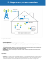
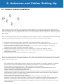
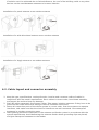
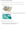
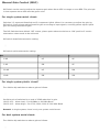
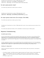
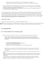
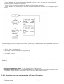
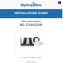
INSTALLATION GUIDE
Mobile Signal Repeater
NS-2500GDW
900, 1800, 900G, 1800G, 2100 MHz
Coverage: 2000 m2
Preface
This user’s manual describes the installation and maintenance of wide band consumer boosters. Please
do read user manual carefully before installing and maintaining repeaters. The information in this
manual is subject to change without prior notice.
1. Safety Warnings
Users must follow the principles below?
Repeater should follow system requirements; assure good grounding and
lightning protection.
The power supply voltage of repeater should meet security requirements; any
operation shall be carried out only after turning off power in advance. Only
the professional is authorized for the operation.
Do not dismantle machine, maintain or replace its components by yourself,
because this way the equipment may be damaged and you may even get an
electric shock.
Do not open the repeater, touch the module of the repeater, or open the
cover of the module to touch electronic component. The components will be
damaged due to electrostatic.
Please keep away from heating equipment, because the repeater dissipates
heat during working. And do not cover a booster with anything that influences
heat dissipation.
2. Introduction and Reasons for Weak
Cellular Signals
Cell Phone Signal Booster is a perfect solution for providing improvement of cellular signal reception
inside a house, office, restaurant, VIP Room, apartment, building or shopping mall.
Generally cell phones cannot pick up or maintain a strong cellular signal due to one of the two following
reasons:
1. Location of the Nearest Base Station – Base stations are used to provide broad coverage.
However there are many areas in which signal strength gets reduced due to topographic peculiarities or
local Governmental restrictions regarding the height or location of base stations. Rural areas generally
have fewer base stations than urban regions.
2. Natural and Man-Made Obstructions – Signal strength can also be negatively affected by trees,
hills, buildings, weather and other obstructions. You may be relatively close to a base station but still
unable to make a call. This often occurs inside houses, offices and other buildings with stucco, concrete
or metal walls that may block the signal.
The Signal Booster works with two antennas. An Indoor antenna communicates with your cell phone and
an Outdoor antenna communicates with the base station (BS). The Outdoor antenna receives a signal
from the BS and sends it through the cable to the Signal Booster, where it gets amplified and retransmitted by the Indoor antenna throughout a building. When the Indoor antenna picks up a signal
from your cellular device, the Signal Booster amplifies that signal and transmits it through the cable to
the Outdoor antenna and back to the BS.
(Note: The Signal Booster will only operate if there is an adequate signal to amplify.)
3. Model Description
Phone reception booster NS2500 GDW is a new triband model designed for boosting GSM/EGSM and 3G
signals in big locations up to 2000m2 (21500 ft2). The device is appropriate for installation in big
private houses, offices, supermarkets, facilities located in underground areas, etc. The booster amplifies
signals on three frequencies at the same time: GSM 900 MHz and 1800 MHz and 3G 2100 MHz
which are compatible with all mobile operators in the European Union, North and South America,
Africa and Asia.
This Triband repeater is meant to improve poor mobile reception which makes the device suitable for
different providers. It also ensures stable 3G data transfer due to which users get easy access to mobile
applications, fast internet, mobile TV and online games.
The reception booster corresponds to the international safety and usage requirements. It’s proved by CE
and RoHS certifications all our boosters have.
Order Nikrans NS2500 GDW cellular phone signal booster and GSM and 3G connections will become
stable forever!
4. Specification
Indoor coverage:
2000 m2
Up-link freq:
880-915MHz, 1710-1785MHz, 1920 MHz
Down-link freq:
925-960MHz, 1805-1880MHz, 2110 MHz
Up-link Gain:
65 dB
Down-link Gain:
70 dB
Power supply:
DC 12V/7A
Working t °C:
-25 -+ 55
Humidity:
5%< 85%
Size (mm):
250 × 330 × 53
Booster Weight:
2,9 kg
Package Weight:
5,5 kg
dBm:
20
5. Repeater system overview
A repeater kit includes:
• Outdoor Antenna?
Outdoor panel or wide band Yaggi is recommended.
Function: To pick up outside signals from the base station and send them by cable to the
repeater; outdoor antenna also transmits the uplink signals from the repeater back to the base
station.
• Indoor Antenna:
It is mounted inside a building to transmit the improved signals throughout the coverage area.
• Cables: Сoaxial cables for indoor and outdoor antennas.
• Mountings: Special mountings for antennas and the booster (depends on a booster model)
• Power Supply
Optionally:
• Splitters or couplers: when the building structure is too complicated or there is big loss due to
thick walls or other reasons, splitters or couplers shall be used so that more antennas can be
installed in separate zones to distribute the signals to each corner of the coverage area.
• Additional indoor antennas: when the building structure is too complicated
6. Antennas and Cables Setting Up
6.1. Outdoor antenna installation
The repeater’s main function is to improve weak RF signals in an area. The formula is: Input power +
Gain= Output power. The signal strength from an outdoor antenna directly affects the efficiency of the
indoor coverage. It is very important to choose the correct outdoor antenna location in order to get the
best signal.
If you don't know exactly where your operator's base station is located, go through the antenna aiming
process for getting the best result. To aim the antenna correctly, follow the steps below:
1. Setup the entire booster system, including antennas and cables, and power it on.
2. A person on the roof aims the antenna in a certain direction. The other person inside waits for 1
minute and checks signal level on the phone.
3. Then rotate the antenna its 1/8th of the way around, which equals 45 degrees. The person
inside does the same procedure with signal testing.
4. Repeat the process 8 times until you try all 8 directions, in every 45 degrees sector.
5. Compare the results of signal testing – the closer dB parameter to 0, the better booster
performance you get.
6. Fix the antenna in the direction with better signal result.
Note! We recommend mounting the antenna on the side of the building aiming away from the building,
which will reduce amount of possible obstacles. For your convenience and acceleration of the process
perform the testing in pair.
• The mobile phone shall display full bar signals in location where the outdoor antenna is installed
Phone calls or data transmission shall be smooth and stable. It is recommended to test the
signal 3 times in location where an outdoor antenna is to be installed
As shown from the illustration above, you should test the signals in points from A to E, and
select a best place that displays full bar signals.
• Outdoor antenna installation Requirements:
Outdoor antenna should be installed on the roof of the house or in some other place where your
mobile device is within coverage zone. Mobile signal should be as strong that at least three-four
bars are indicated on your phone display.
Outdoor antenna should be fixed in straightly.
It is necessary to waterproof connectors of the outdoor antenna and feeder lines.
Repeater is a two-way signal amplifier. So proper isolation between outdoor antenna and indoor
antenna is necessary in order to avoid self-oscillation. A perfect example of self-oscillation is
when you take a MIC and a loudspeaker for example; if they are too close to each other, it could
cause big noise.
If isolation can’t be achieved due to limited distance, the roof of the building, walls or any other
barriers can be used between antennas to increase isolation.
Installation of a panel antenna as an outdoor antenna
Installation of a wide directional antenna as an outdoor antenna
Installation of a Yaggi antenna as an outdoor antenna
6.2. Cable layout and connector assembly
1. Keep the type, specifications, routing direction, location and curvature radius of cables in
compliance with the model requirements. Place cables in correct order, bend them smoothly,
and protect the surface from any damage.
2. Place RF cables separately from power cables. Take proper isolation measures if they have to be
placed on the same cable racks owing to the site condition restrictions.
3. Fasten all connection parts of the whole system in correct order, from the antenna to repeater
interfaces, and make sure that the electrical interfaces are well contacted. Give waterproof
treatment to outdoor connection parts.
4. Take lightning protection measures for the antenna and feeder system in accordance with the
system requirements. Avoid deforming the antenna feeder where grounding clips are placed,
and give waterproof treatment to the feeder.
6.3. Indoor antenna installation
Correct antennas types shall be used according to the site conditions and the requirement.
1. Omni antenna (ceiling Omni or whip antenna) shall be installed in the center and radiate all
directions.
2. It is better to use a directional panel antenna or Yaggi antenna when the area shape is long and
narrow (corridors, long row of houses in two sides, tunnels or elevators or rural open space).
Requirements to indoor antenna installation:
• indoor antenna should be 5 meter distance from an outdoor antenna
• indoor antenna should be at least 2 meters above the ground
• indoor antenna should be fixed vertically with the ground.
7. Repeater Installation
7.1. Installation requirements
7.1.1. Installation Location Requirements
1. The repeater shall be installed indoor in a cool, dry and ventilated room without erosive gas or
smoke, or on a cool and ventilated wall to ensure excellent heat dissipation.
2. Installation height should be sufficient for RF cable wiring, heat dissipation and maintenance.
3. Independent and stable power supply is necessary.
7.1.2. Power requirement
Generally AC 100~264V AC / 50±5Hz power supply is required.
7.2. Installation Steps
7.2.1. Installation schemes
INSTALLATION STEPS
1.
2.
3.
4.
Find an appropriate position for an outdoor antenna. (see the requirements in 6.1. sect. )
Plug in the outdoor antenna to the mobile booster from BS side and fasten tightly.
Plug in the indoor antenna to the mobile booster from MS side and fasten tightly.
Connect the signal booster to the Power Supply.
!Some models have an inbuilt Power Supply. Please, examine the manual applied to your model,
if your signal repeater kit doesn’t include separate Power Supply, skip this step!
If the light indicator on the booster turns on it means the installation has been implemented
correctly.
NOTE: Switch on the signal booster only after you connect outdoor and indoor antennas in the
proper way!
5. Test the signal of your mobile telephone – a maximum quantity of bars should be indicated on
the display of your phone in each corner of the location within booster coverage zone. In case
the mobile signal is still instable try to change the position of the outdoor antenna for more
proper one.
Important notes for installation:
1. Cables from outdoor antenna should not be wound and be placed as straight as possible in order
not to create any hindrance for signal reception and its transmission.
2. Cables should be shortened to the acceptable maximum so that not to waste or decrease mobile
signal coverage range.
3. In order to prevent water from coming into the mobile phone booster through the cable make a
loop in it.
4. Keep the outdoor antenna as far as possible from frequency aerials, high voltage cables, metal
nets or transformers.
5. Never point the front of a Directional outdoor antenna towards the indoor antenna.
6. Plug the power supply into the Signal Booster input (carefully, to avoid damaging the center pin)
and then into a wall outlet.
Note: It is recommended to plug all AC power supplies for home electronics into a Surge
Protector Power Strip.
7. If the light indicator doesn’t turn on, please see the lights indication instructions.
8. Using multiple Signal Boosters in one installation could cause interference to the base station
(except for the In-Line Signal Boosters).
7.2.2. Repeater’s ports description
1. Outdoor port: connected with the outdoor antenna by cable
2. Indoor port: connected with indoor antenna directly or by cable
3. DC IN: connected with power supply.
7.2.3. Accessories selection
Choosing accessories pay attention to the two characteristics – frequency and impedance. All
accessories shall support the repeater’s frequencies. For example, if the repeater’s frequency is
GSM900, all the accessories must support the GSM900 frequency.
7.3. Repeater Settings
7.3.1. Indicator Light Instructions
After power is on, check firstly the alarm and power LEDS.
Status and definition of POWER indicators:
Status
Definition
Green
Normal
Off
Power problem
Status and Definition of ALARM LED indicators; Alarm LED only works for downlink signals.
Status
ALARM
It is working in linearity
Green
Warning: Input signals may be not enough, so please check on coverage effect, do not
do anything if it is good coverage; otherwise please adjust the repeater system to get
better coverage.
A little bit stronger input signals or slight self oscillation have occurred.
Orange
Red for
5
seconds
and
then off
Solution: Please adjust antennas or use MGC to reduce the repeater gain, till you find
“edge point” with green LED (I.E. the Alarm LED must stay at green color, and at the
edge of turning Orange), and let the repeater work at this point. MGC is the last
measure to take as it will shorten the coverage.
There are strong input signals or severe self oscillations (loop), please enlarge the
distance or make use of barriers between antennas, or adjust the antennas’ angles,
and last step is to adjust the repeater by DIP switch.
Remark: Please note that Alarm LED works on repeater downlink signals only. I.E. the repeater input
signals from CELL TOWER.
Single system repeater only has one set of power and alarm LEDS, while dual system have two sets of
power and alarm LEDS, and three system repeaters have three sets of LEDS. Each system has own
relevant LED and please refer to the correct LED for system performance evaluation.
Then repeater with plastic closet is designed with LEDS of “Alarm LOW” and “Alarm HIGH”. When it is
used for single system of CDMA800, GSM850 and GSM900, only “Alarm Low” LED works, and “Alarm
HIGH” LED is no use; when it is used for single system of DCS, PCS, CDMA1900, WCDMA or AWS, “Alarm
HIGH” LED works, and “Alarm LOW” LED is no use. When the repeater supports two systems, “Alarm
Low” and “Alarm HIGH” both work and support relevant low and high frequencies.
Manual Gain Control (MGC)
DIP Switch can be used to adjust the repeater gain when Alarm LED is orange or even RED. The principle
is that repeater alarm LED must be green color.
For single system metal closet:
Switches 1.2 represent Downlink and 3.4 represent Uplink. When it is necessary to adjust the gain by
DIP switch, firstly please adjust Downlink gain according to input signals, secondly please adjust Uplink
gain according to Downlink gain.
The DIP Switches have default ‘OFF’ status; please push relevant switches to “ON” position if certain
attenuation value needs to be achieved.
DIP switch downlink attenuation setting:
DIP switch uplink attenuation setting:
Att
3
4
0 dB
off
off
5 dB
ON
off
10 dB
off
ON
15dB
ON
ON
For single system plastic closet?
Turn ON the dip switches to reduce gain as follows:
Put ON a pair of switches for a total of 15dB reduction in gain.
(DL1 & UL1 – Alarm Low) – For 800MHz or 900 MHz Band
(DL2 & UL2 – Alarm High) – For 1700, 1800, 1900 & 2100 MHz Band
Remark: In single system, there is only one system could be set.
For dual system metal closet:
Turn ON the dip switches to reduce gain as follows:
Put ON a pair of switches for a total of 15dB reduction in gain.
(DL1 & UL1 – Alarm Low) – For 800MHz or 900 MHz Band
(DL2 & UL2 – Alarm High) – For 1700, 1800, 1900 & 2100 MHz Band
For dual system plastic closet?
Turn ON the dip switches to reduce power as follows:
Put ON a pair of switches for a total of 15dB reduction in gain.
(DL1 & UL1 – Alarm Low) – For 800MHz or 900 MHz Band
(DL2 & UL2 – Alarm High) – For 1700, 1800, 1900 & 2100 MHz Band
For triple system metal closet (For example: F10I-GDW)
Turn ON the dip switches to reduce gain as follows:
Put ON a pair of switches for a total of 15dB reduction in gain. You can reduces anyone system in the
products.
Turn ON the dip switches of GSM or DCS or WCDMA to reduce the gain of GSM system.
Repeater Commissioning
Downlink gain setting
First the alarm LED only indicates the downlink input power level, here we use color of Alarm LED to
adjust the gain of the repeater. Alarm LED color must remain green. As for the downlink working
performance, it is a good working point that Alarm LED maintains “Green” color with the intention of
turning orange; here we refer as “edge point”. At this time, downlink output power and coverage effect
are stable.
And the equipment must be as far as possible away from overloading status of “red” (the equipment
would hold higher interference and depression ability at this stage). So we shall try our best to set the
equipment near “edge point” of green and intention of turning orange during engineering.
Setting of “edge point”:
Switch on the power supply after connection with donor antenna and server antenna, and observe
ALARM LED.
• If it shines “orange”, use 1dB as step to reduce the gain until “green” turns on, then increase the
gain 1~3dB attenuation value until “orange” starts to turn on, then brings back 1~2dB till
“green” is on, then fix the gain and the repeater’s downlink output power reaches the perfect
status.
• If it shines “green” then:
◦ Please check coverage effect firstly, if the coverage effect is good, the
engineering has reached expecting target, thus there is no need to do anything.
• To check whether the attenuation value has been set, if it is, use 1dB as step to increase gain
until the “orange” turns on, then brings back 1~2dB till “green” is on again , then the repeater’s
downlink output power reaches the perfect status.
• But if attenuation has not been set, it indicates that the input power is not strong enough to let
the repeater reach its good coverage.
If the coverage effect is not good, the donor antenna should be adjusted to get stronger input signal. It
is recommended that one person shall check the coverage effect inside the building when the other
person is trying to adjust the antenna or the repeater. At this stage, please make sure “Orange” color
will not be generated by self oscillation. Please take off the server antenna to check if it is self oscillation
or not: if the Orange turns to be green, it is self oscillation; if it stays as Orange, it is not self oscillation.
Please follow steps in other page to turn Orange to be Green.
Uplink gain setting
Standard: uplink attenuation values =downlink attenuation values
Remark: Avoid putting more than a 5dB difference between the Uplink and Downlink. And Uplink gain must be
equal to or less than Downlink gain, it can’t be more in order to avoid interference with mobile network.
7.4. System Test
7.4.1. Check whether the coverage is good
1. Take a test with a mobile phone or a data card (engineering mobile phone is preferred).
To test signal level with a cell phone, make use of its engineering mode (Field Test
Mode), which is an application available in free access or a phone mode requiring no
extra setups. On most used mobile OS (operating systems) the test mode can be started
as follows:
◦
◦
◦
◦
iOS. Type *3001#12345#* and hit Call
Android. Type *#*#197328640#*#* to activate
Windows. Type ##3282# and start.
Blackberry. Press TOOLS, SETTINGS, STATUS or OPTIONS, STATUS.
Note! To get parameters for 2G, 3G and LTE, disable WiFi. In case you cannot find Field
Test Mode on your cell phone, use bars on the screen of your mobile phone to evaluate
the change.
If the signals in most areas have not been improved, please check recommendations below
again:
- Weak input signal leads to low output power. To increase input signal power level, change the
direction of the outdoor antenna or its installation position or replace it for an antenna with
higher gain.
- Check whether it is necessary to use additional indoor antennas as barriers block signal
penetration; also check whether the repeater’s power is enough; please install extra indoor
antennas or replace the repeater for another model with higher power level.
2. If the signals in small parts of the area have not been improved, please check the following:
- Check whether the indoor antenna is installed correctly or not; you may try to change the
antenna location to improve coverage.
- Check if it is necessary to adjust the direction of the indoor antenna.
- Check whether it is necessary to add one or more antennas to enhance the coverage in special
areas.
For maximum precision in signal level testing, switch your cell phone into Field Test Mode and see dB
parameter. The closer dB signal level to 0, the better cell phone reception you’ll get.
•
•
•
•
•
-105 to -100 = Bad/drop call
-99 to -90 = Getting bad/signal may break up
-89 to -80 = OK/shouldn't have problems, but maybe
-79 to -65 = Good
Over -65 = Excellent
Your task is to get at least -79dB signal to ensure reliable communication and strong signal inside the
building.
Remark:
• Reduce attenuation values * — by ensuring the isolation level
• Increase output power * — recommended ways: to adjust outdoor antenna direction/location,
or replace it to an antenna with higher gain to increase input signal strength.
7.4.2. Repeater can not communicate in Power-ON status
1. The power is on but there is a signal fluctuation or a flash signal. The phone call cannot be
made/received.
It shall be caused by the insufficient isolation between outdoor and indoor antennas.
Please take the following measures:
- Firstly check whether the alarm LED lights. The light may indicate the isolation is insufficient.
- Secondly adjust the antennas’ directions or locations or enlarge distance between them.
- Thirdly reduce the repeater’s gain by ATT DIP if the above listed methods don’t work.
The following measures can also be helpful:
- Use the roof of the building to enlarge isolation (Please try to place the outdoor antenna and
indoor antenna on different floors).
- Use some obstacles (Such as walls).
2. The repeater’s power is on but the phone cannot get connected to the network and still can not
communicate.
Reason 1: There are loose or wrong connections in the repeater system.
Solution: Please try to fasten the connections between different parts of the system.
Reason 2: The signals received by outdoor antenna of other operators nearby are too strong.
(For example, the other operators’ signals are 10 dB stronger than the needed signals.)
Solution 1: Change the direction of the outdoor antenna or its installation position, so that the
gap of signal strength is reduced between operators.
Solution 2: Use barriers (like buildings and walls) to block signals from other operators.
8. FAQ
1. Will booster increase the RF radiation?
No, it will decrease instead.
Every cell phone irradiates heavily being in zones with poor mobile signal as a cell phone is constantly in
searching mode. The danger is your cell phone is about 2cm to your body, which makes its usage rather
harmful. And when a booster is installed, it improves the mobile signals in the coverage, and your cell
phone stops irradiating strongly, thus it will reduce the RF radiation of the mobile phone tremendously.
The maximum power level of booster is 0.01W, and it decreases to be maximum 0.001W when reaching
indoor antenna. And since the indoor antenna is installed over the ceiling or onto the wall, there is
usually more than 3 meter away from the human body, 3meter away means at least 40dB propagation
loss, or 10000 times less, 0.0000001W, and therefore it is too weak to influence human bodies though it
is still a very good signal for mobile phones.
2. If the power indicator is off after installing the repeater, what should
I do?
Check if the repeater’s power supply works normally or not.
3. If repeater’s power supply is normal, ALM light is on or flashing all
the time, what should I do?
Firstly, check whether all connectors are connected well or not. If it is all right, please, adjust the
direction of the outdoor and indoor antenna. Make sure the horizontal distance is 75 feet or more, the
vertical distance is 20 feet or more.
4. If the repeater and power supply are installed correctly, why the
signal is still bad?
1. According to the steps above, verify if all the cables and connectors are connected correctly or not
and correct the connections if necessary.
2. If connections are correct, please, adjust the direction of the outdoor antenna, point it towards BTS
antenna, and make sure it can accept the strongest signal.
5. After installing the repeater, the signal is good, but the connection
is slow or intermittent, or I cannot hear clearly the other side?
1. Please, check the indoor antenna position, and whether the cables and connectors are connected
correctly or not.
2. Adjust the indoor antenna direction and make sure it can easily receive a cell phone signal.
9. About Nikrans Brand
Nikrans boosters is the result of a 7-year experience in selling cell phone signal amplifiers throughout
EMEA, APAC, NAR and other regions. For all these years we’ve been following the market carefully
listening to customers and industry leading experts with the aim of working up our own vision and
quality standards in signal amplification.
Nikrans product line includes about 40 models: from basic single-band devices with 100 m2 coverage to
high-end all-in-one solutions covering up to 5000 m 2. Depending on the model, boosters operate in
GSM, DCS, CDMA, LTE or combination of these standards at 850-2100 MHz frequencies. The product line
is extended with a series of antennas, splitters and other accessories for completing exclusive custom
projects of any difficulty level.
Nikrans product development process is rigorously assessed to comply with ISO 9001:2008 standard
and implicates internal tests, which greatly ensures the quality of our goods. High product quality is also
confirmed by Phoenix Testlab, Germany and is proved with CE and RoHS certificates. That’s why a
2-year warranty applies to any of Nikrans boosters.
Certificates
+44 2037691854 (UK) · +33 975122740 (France) · +16178610605 (US)
E-mail: [email protected] · Skype: gsm_amplifier
www.myamplifiers.com