1
Cat. No. V062-E1-05
NT31 and NT31C
Programmable Terminals
Setup Manual
NT31 and NT31C
Programmable Terminals
Setup Manual
Revised October 2010
POW
ER
RUN
iv
Notice:
OMRON products are manufactured for use according to proper procedures by a qualified operator
and only for the purposes described in this manual.
The following conventions are used to indicate and classify precautions in this manual. Always heed
the information provided with them. Failure to heed precautions can result in injury to people or damage to property.
!DANGER
Indicates an imminently hazardous situation which, if not avoided, will result in death or
serious injury. Additionally, there may be severe property damage.
!WARNING
Indicates a potentially hazardous situation which, if not avoided, could result in death or
serious injury. Additionally, there may be severe property damage.
!Caution
Indicates a potentially hazardous situation which, if not avoided, may result in minor or
moderate injury, or property damage.
OMRON Product References
All OMRON products are capitalized in this manual. The word “Unit” is also capitalized when it refers to
an OMRON product, regardless of whether or not it appears in the proper name of the product.
The abbreviation “Ch,” which appears in some displays and on some OMRON products, often means
“word” and is abbreviated “Wd” in documentation in this sense.
The abbreviation “PLC” means Programmable Controller. “PC” is used, however, in some Programming Device displays to mean Programmable Controller.
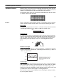
Visual Aids
The following headings appear in the left column of the manual to help you locate different types of
information.
Note Indicates information of particular interest for efficient and convenient operation of the product.
1,2,3...
1. Indicates lists of one sort or another, such as procedures, checklists, etc.
OMRON, 2000
All rights reserved. No part of this publication may be reproduced, stored in a retrieval system, or transmitted, in any form, or
by any means, mechanical, electronic, photocopying, recording, or otherwise, without the prior written permission of
OMRON.
No patent liability is assumed with respect to the use of the information contained herein. Moreover, because OMRON is constantly striving to improve its high-quality products, the information contained in this manual is subject to change without
notice. Every precaution has been taken in the preparation of this manual. Nevertheless, OMRON assumes no responsibility
for errors or omissions. Neither is any liability assumed for damages resulting from the use of the information contained in
this publication.
v
vi
TABLE OF CONTENTS
PRECAUTIONS . . . . . . . . . . . . . . . . . . . . . . . . . . . . . . . . . . .
xv
1
Intended Audience . . . . . . . . . . . . . . . . . . . . . . . . . . . . . . . . . . . . . . . . . . . . . . . . . . . . . . . . .
xvi
2
General Precautions . . . . . . . . . . . . . . . . . . . . . . . . . . . . . . . . . . . . . . . . . . . . . . . . . . . . . . . .
xvi
3
Safety Precautions . . . . . . . . . . . . . . . . . . . . . . . . . . . . . . . . . . . . . . . . . . . . . . . . . . . . . . . . .
xvi
SECTION 1
General. . . . . . . . . . . . . . . . . . . . . . . . . . . . . . . . . . . . . . . . . . .
1
1-1
Role and Operation of the NT31/NT31C . . . . . . . . . . . . . . . . . . . . . . . . . . . . . . . . . . . . . . .
2
1-2
Functions of the NT31/NT31C . . . . . . . . . . . . . . . . . . . . . . . . . . . . . . . . . . . . . . . . . . . . . . .
4
1-3
System Configuration . . . . . . . . . . . . . . . . . . . . . . . . . . . . . . . . . . . . . . . . . . . . . . . . . . . . . .
15
1-4
Communications with the Host . . . . . . . . . . . . . . . . . . . . . . . . . . . . . . . . . . . . . . . . . . . . . . .
16
1-5
Communications Using Memory Links . . . . . . . . . . . . . . . . . . . . . . . . . . . . . . . . . . . . . . . .
19
1-6
Before Operating . . . . . . . . . . . . . . . . . . . . . . . . . . . . . . . . . . . . . . . . . . . . . . . . . . . . . . . . . .
21
SECTION 2
Preparing for Connection . . . . . . . . . . . . . . . . . . . . . . . . . . .
23
2-1
Method for Connection to the Host . . . . . . . . . . . . . . . . . . . . . . . . . . . . . . . . . . . . . . . . . . . .
24
2-2
Names and Functions of Parts . . . . . . . . . . . . . . . . . . . . . . . . . . . . . . . . . . . . . . . . . . . . . . . .
27
SECTION 3
Hardware Settings and Connections. . . . . . . . . . . . . . . . . . .
29
3-1
Installation . . . . . . . . . . . . . . . . . . . . . . . . . . . . . . . . . . . . . . . . . . . . . . . . . . . . . . . . . . . . . . .
30
3-2
Connecting to the Support Tool . . . . . . . . . . . . . . . . . . . . . . . . . . . . . . . . . . . . . . . . . . . . . . .
33
3-3
Connecting a Printer . . . . . . . . . . . . . . . . . . . . . . . . . . . . . . . . . . . . . . . . . . . . . . . . . . . . . . .
34
3-4
Connecting a Bar Code Reader . . . . . . . . . . . . . . . . . . . . . . . . . . . . . . . . . . . . . . . . . . . . . . .
34
3-5
Using a Memory Unit . . . . . . . . . . . . . . . . . . . . . . . . . . . . . . . . . . . . . . . . . . . . . . . . . . . . . .
36
SECTION 4
Connecting to the Host from the RS-232C Port. . . . . . . . . .
45
4-1
Connecting to the RS-232C Port at the Host . . . . . . . . . . . . . . . . . . . . . . . . . . . . . . . . . . . . .
46
SECTION 5
Connecting to the Host from the RS-422A/485 Port . . . . . .
79
5-1
Connecting to the Host’s RS-232C Port . . . . . . . . . . . . . . . . . . . . . . . . . . . . . . . . . . . . . . . .
80
5-2
Connecting to the Host’s RS-422A/485 Port. . . . . . . . . . . . . . . . . . . . . . . . . . . . . . . . . . . . .
94
SECTION 6
System Menu Operation. . . . . . . . . . . . . . . . . . . . . . . . . . . . . 131
6-1
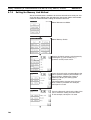
System Menu Operation Flow . . . . . . . . . . . . . . . . . . . . . . . . . . . . . . . . . . . . . . . . . . . . . . . .
133
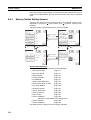
6-2
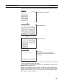
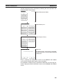
Starting the NT31/NT31C . . . . . . . . . . . . . . . . . . . . . . . . . . . . . . . . . . . . . . . . . . . . . . . . . . .
133
6-3
Operation Modes and the System Menu . . . . . . . . . . . . . . . . . . . . . . . . . . . . . . . . . . . . . . . .
135
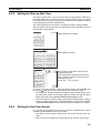
6-4
Memory Initialization . . . . . . . . . . . . . . . . . . . . . . . . . . . . . . . . . . . . . . . . . . . . . . . . . . . . . .
140
vii
TABLE OF CONTENTS
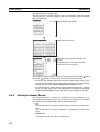
6-5
Operations in the System Installer Mode. . . . . . . . . . . . . . . . . . . . . . . . . . . . . . . . . . . . . . . .
150
6-6
Transmitting the Screen Data . . . . . . . . . . . . . . . . . . . . . . . . . . . . . . . . . . . . . . . . . . . . . . . .
155
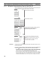
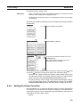
6-7
Setting Conditions for Communications with Host by Using Memory Switches . . . . . . . . .
158
6-8
Starting Operation . . . . . . . . . . . . . . . . . . . . . . . . . . . . . . . . . . . . . . . . . . . . . . . . . . . . . . . . .
169
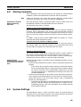
6-9
System Settings . . . . . . . . . . . . . . . . . . . . . . . . . . . . . . . . . . . . . . . . . . . . . . . . . . . . . . . . . . .
169
6-10 Setting the Bar Code Reader Input Function. . . . . . . . . . . . . . . . . . . . . . . . . . . . . . . . . . . . .
189
6-11 System Maintenance . . . . . . . . . . . . . . . . . . . . . . . . . . . . . . . . . . . . . . . . . . . . . . . . . . . . . . .
191
6-12 Programming Console Function . . . . . . . . . . . . . . . . . . . . . . . . . . . . . . . . . . . . . . . . . . . . . .
219
6-13 Device Monitor Function. . . . . . . . . . . . . . . . . . . . . . . . . . . . . . . . . . . . . . . . . . . . . . . . . . . .
225
6-14 Version Display . . . . . . . . . . . . . . . . . . . . . . . . . . . . . . . . . . . . . . . . . . . . . . . . . . . . . . . . . . .
228
SECTION 7
Troubleshooting and Maintenance . . . . . . . . . . . . . . . . . . . . 231
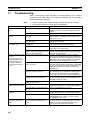
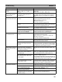
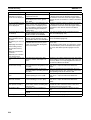
7-1
Troubleshooting . . . . . . . . . . . . . . . . . . . . . . . . . . . . . . . . . . . . . . . . . . . . . . . . . . . . . . . . . . .
232
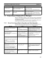
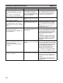
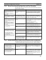
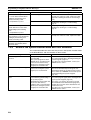
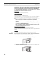
7-2
Responding to Displayed Error Messages. . . . . . . . . . . . . . . . . . . . . . . . . . . . . . . . . . . . . . .
235
7-3
Maintenance of the NT31/NT31C . . . . . . . . . . . . . . . . . . . . . . . . . . . . . . . . . . . . . . . . . . . . .
241
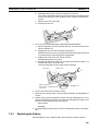
7-4
Inspection and Cleaning . . . . . . . . . . . . . . . . . . . . . . . . . . . . . . . . . . . . . . . . . . . . . . . . . . . .
245
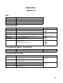
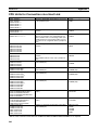
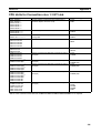
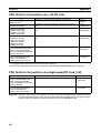
Appendices
A
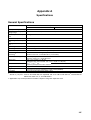
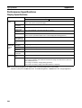
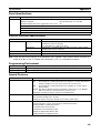
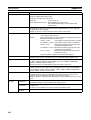
Specifications . . . . . . . . . . . . . . . . . . . . . . . . . . . . . . . . . . . . . . . . . . . . . . . . . . . . . . . . . . . .
247
B
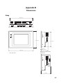
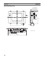
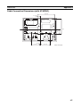
Dimensions . . . . . . . . . . . . . . . . . . . . . . . . . . . . . . . . . . . . . . . . . . . . . . . . . . . . . . . . . . . . . .
255
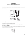
C
Using an RS-232C/RS-422A Adapter . . . . . . . . . . . . . . . . . . . . . . . . . . . . . . . . . . . . . . . . .
259
D
Transporting and Storing the NT31/NT31C . . . . . . . . . . . . . . . . . . . . . . . . . . . . . . . . . . . . .
265
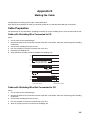
E
Making the Cable . . . . . . . . . . . . . . . . . . . . . . . . . . . . . . . . . . . . . . . . . . . . . . . . . . . . . . . . .
267
F
Making the Cable for Connecting a PLC . . . . . . . . . . . . . . . . . . . . . . . . . . . . . . . . . . . . . . .
269
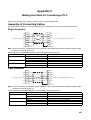
G
Making the Cable for Connection to a Bar Code Reader . . . . . . . . . . . . . . . . . . . . . . . . . . .
271
H
Making the Cable for Connection to a Printer . . . . . . . . . . . . . . . . . . . . . . . . . . . . . . . . . . .
273
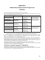
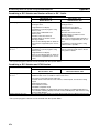
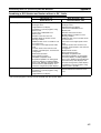
I
Relationship between System Program and Hardware . . . . . . . . . . . . . . . . . . . . . . . . . . . . .
275
J
Model List . . . . . . . . . . . . . . . . . . . . . . . . . . . . . . . . . . . . . . . . . . . . . . . . . . . . . . . . . . . . . . .
279
K
Option List . . . . . . . . . . . . . . . . . . . . . . . . . . . . . . . . . . . . . . . . . . . . . . . . . . . . . . . . . . . . . .
285
Index. . . . . . . . . . . . . . . . . . . . . . . . . . . . . . . . . . . . . . . . . . . . . 289
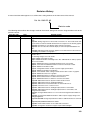
Revision History . . . . . . . . . . . . . . . . . . . . . . . . . . . . . . . . . . . 293
viii
About this Manual:
This manual describes connecting the NT-series NT31 and NT31C Programmable Terminals to a PLC
(Programmable Controller) or other host and peripheral devices and the settings required for communications and applications. It includes the sections described below.
Please read this manual carefully and be sure you understand the information provided before
attempting to install and operate the Programmable Terminal.
Section 1 provides fundamental information about the functions and features of the PTs, types of connection, communications methods, etc. This information will enable you to understand the applications
of the PTs.
Section 2 describes the connection methods that are possible with the PTs, and the functions of the
parts of PTs, as the required knowledge before connecting to the host and to the peripheral devices.
Section 3 describes the settings of the PTs and methods for connection to peripheral devices.
Section 4 describes the method for connecting to the host using the RS-232C port of the PT.
Section 5 describes the method for connecting to the host using the RS-422A/485 port of the PT.
Section 6 describes the operation of the System Menu, focusing on the procedure to start the PT.
Functions that are convenient when using the PT and those that are useful for system maintenance
are also explained here.
Section 7 describes the action to take when errors occur in the PT, and how to carry out maintenance
and inspection to prevent the occurrence of errors.
The Appendices provide specifications, dimensions, procedures for using an RS-232C/RS-422A
Adapter, procedures for transporting and storing the PT, information on cable preparation, information
on the relationship between the system program and hardware, and product lists.
!WARNING Failure to read and understand the information provided in this manual may result in personal injury or death, damage to the product, or product failure. Please read each section
in its entirety and be sure you understand the information provided in the section and
related sections before attempting any of the procedures or operations given.
ix
Related Manuals:
Related manuals are listed below.
The @ symbol at the end of the catalog number is the revision number.
Connecting and Setting Up the Programmable Terminal
• NT31 and NT31C PT Setup Manual (V062-E1-@, this manual)
This manual describes connecting the Programmable Terminals to a host and peripheral devices and
settings required for communications and applications.
The functions and actual operating methods for the NT31 and NT31C PTs are provided in the Reference Manual (V064-E1-@).
Programmable Terminal Functions and Operation
• NT31/31C/631/631C PT Reference Manual (V064-E1-@)
This manual is used for any of the following PTs: NT31, NT31C, NT631, and NT631C. It describes
screen configurations, part functions, host control methods, and other application information.
PT connection and setup procedures are described in the NT31 and NT31C PT Setup Manual (V062E1-@).
Creating and Transferring Screen Data, and Installing the
System Program
• NT-series Support Tool for Windows Ver. 4.@ Operation Manual (V061-E1-@)
The screens displayed on the NT31 and NT31C PTs are created with the Support Tool and transferred
to the PT. This manual describes how to create and transfer screen data. It also describes how to
download a system program to a PT using the System Installer.
The NT-series Support Tool for Windows is normally referred to as merely the Support Tool.
Connecting to Controllers Not Made by OMRON
• PLC Connection Manual (V042-E1-@)
The NT31 and NT31C PTs can be connected to controllers in the following series: Mitsubishi A Series
and FX Series. This manual describes the connection and setup methods for these controllers.
The NT-series Support Tool for Windows Version 4.@ is required to connect the NT31 and NT31C PTs
to these controllers.
• NT31/NT631 Multi Vendor Connection Manual (V060-E1-@)
The NT31 and NT31C PTs can be connected to controllers in the following series: Allen-Bradley SLC
500 Series, GE Fanuc 90-20 and 90-30 Series, and Siemens S7-300 and S7-400 Series. This manual
describes the connection and setup methods for these controllers.
x
Read and Understand this Manual
Please read and understand this manual before using the product. Please consult your OMRON
representative if you have any questions or comments.
Warranty and Limitations of Liability
WARRANTY
OMRON's exclusive warranty is that the products are free from defects in materials and workmanship for a
period of one year (or other period if specified) from date of sale by OMRON.
OMRON MAKES NO WARRANTY OR REPRESENTATION, EXPRESS OR IMPLIED, REGARDING NONINFRINGEMENT, MERCHANTABILITY, OR FITNESS FOR PARTICULAR PURPOSE OF THE
PRODUCTS. ANY BUYER OR USER ACKNOWLEDGES THAT THE BUYER OR USER ALONE HAS
DETERMINED THAT THE PRODUCTS WILL SUITABLY MEET THE REQUIREMENTS OF THEIR
INTENDED USE. OMRON DISCLAIMS ALL OTHER WARRANTIES, EXPRESS OR IMPLIED.
LIMITATIONS OF LIABILITY
OMRON SHALL NOT BE RESPONSIBLE FOR SPECIAL, INDIRECT, OR CONSEQUENTIAL DAMAGES,
LOSS OF PROFITS OR COMMERCIAL LOSS IN ANY WAY CONNECTED WITH THE PRODUCTS,
WHETHER SUCH CLAIM IS BASED ON CONTRACT, WARRANTY, NEGLIGENCE, OR STRICT
LIABILITY.
In no event shall the responsibility of OMRON for any act exceed the individual price of the product on which
liability is asserted.
IN NO EVENT SHALL OMRON BE RESPONSIBLE FOR WARRANTY, REPAIR, OR OTHER CLAIMS
REGARDING THE PRODUCTS UNLESS OMRON'S ANALYSIS CONFIRMS THAT THE PRODUCTS
WERE PROPERLY HANDLED, STORED, INSTALLED, AND MAINTAINED AND NOT SUBJECT TO
CONTAMINATION, ABUSE, MISUSE, OR INAPPROPRIATE MODIFICATION OR REPAIR.
xi
Application Considerations
SUITABILITY FOR USE
OMRON shall not be responsible for conformity with any standards, codes, or regulations that apply to the
combination of products in the customer's application or use of the products.
At the customer's request, OMRON will provide applicable third party certification documents identifying
ratings and limitations of use that apply to the products. This information by itself is not sufficient for a
complete determination of the suitability of the products in combination with the end product, machine,
system, or other application or use.
The following are some examples of applications for which particular attention must be given. This is not
intended to be an exhaustive list of all possible uses of the products, nor is it intended to imply that the uses
listed may be suitable for the products:
• Outdoor use, uses involving potential chemical contamination or electrical interference, or conditions or
uses not described in this manual.
• Nuclear energy control systems, combustion systems, railroad systems, aviation systems, medical
equipment, amusement machines, vehicles, safety equipment, and installations subject to separate
industry or government regulations.
• Systems, machines, and equipment that could present a risk to life or property.
Please know and observe all prohibitions of use applicable to the products.
NEVER USE THE PRODUCTS FOR AN APPLICATION INVOLVING SERIOUS RISK TO LIFE OR
PROPERTY WITHOUT ENSURING THAT THE SYSTEM AS A WHOLE HAS BEEN DESIGNED TO
ADDRESS THE RISKS, AND THAT THE OMRON PRODUCTS ARE PROPERLY RATED AND
INSTALLED FOR THE INTENDED USE WITHIN THE OVERALL EQUIPMENT OR SYSTEM.
PROGRAMMABLE PRODUCTS
OMRON shall not be responsible for the user's programming of a programmable product, or any
consequence thereof.
xii
Disclaimers
CHANGE IN SPECIFICATIONS
Product specifications and accessories may be changed at any time based on improvements and other
reasons.
It is our practice to change model numbers when published ratings or features are changed, or when
significant construction changes are made. However, some specifications of the products may be changed
without any notice. When in doubt, special model numbers may be assigned to fix or establish key
specifications for your application on your request. Please consult with your OMRON representative at any
time to confirm actual specifications of purchased products.
DIMENSIONS AND WEIGHTS
Dimensions and weights are nominal and are not to be used for manufacturing purposes, even when
tolerances are shown.
PERFORMANCE DATA
Performance data given in this manual is provided as a guide for the user in determining suitability and does
not constitute a warranty. It may represent the result of OMRON's test conditions, and the users must
correlate it to actual application requirements. Actual performance is subject to the OMRON Warranty and
Limitations of Liability.
ERRORS AND OMISSIONS
The information in this manual has been carefully checked and is believed to be accurate; however, no
responsibility is assumed for clerical, typographical, or proofreading errors, or omissions.
xiii
xiv
PRECAUTIONS
This section provides general precautions for using the Programmable Terminal.
The information contained in this section is important for the safe and reliable application of the Programmable
Terminal. You must read this section and understand the information contained before attempting to set up or operate
a Programmable Terminal.
1
2
3
Intended Audience . . . . . . . . . . . . . . . . . . . . . . . . . . . . . . . . . . . . . . . . . . . . .
General Precautions . . . . . . . . . . . . . . . . . . . . . . . . . . . . . . . . . . . . . . . . . . . .
Safety Precautions . . . . . . . . . . . . . . . . . . . . . . . . . . . . . . . . . . . . . . . . . . . . .
xvi
xvi
xvi
xv
1
Intended Audience
1
Intended Audience
This manual is intended for the following personnel, who must also have
knowledge of electrical systems (an electrical engineer or the equivalent).
• Personnel in charge of introducing FA systems into production facilities.
• Personnel in charge of designing FA systems.
• Personnel in charge of installing and connecting FA systems.
• Personnel in charge of managing FA systems and facilities.
2
General Precautions
The user must operate the product according to the performance specifications described in the operation manuals.
Before using the product under conditions which are not described in the
manual or applying the product to nuclear control systems, railroad systems,
aviation systems, vehicles, combustion systems, medical equipment, amusement machines, safety equipment, and other systems, machines and equipment that may have a serious influence on lives and property if used
improperly, consult your OMRON representative.
Make sure that the ratings and performance characteristics of the product are
sufficient for the systems, machines, and equipment, and be sure to provide
the systems, machines, and equipment with double safety mechanisms.
This manual provides information for using the Programmable Terminal. Be
sure to read this manual before attempting to use the software and keep this
manual close at hand for reference during operation.
!WARNING It is extremely important that Programmable Terminals and related devices be
used for the specified purpose and under the specified conditions, especially
in applications that can directly or indirectly affect human life. You must consult with your OMRON representative before applying Programmable Terminals to the above-mentioned applications.
!WARNING Do not use input functions such as PT touch switches for applications where
danger to human life or serious damage is possible, or for emergency switch
applications.
3
Safety Precautions
Read these safety precautions carefully and make sure you understand them
before using the Programmable Terminal so that you can use it safely and correctly.
Safety Conventions and Their Meanings
This operation manual uses the following conventions and symbols to indicate
cautions, warnings, and dangers in order to ensure safe use of the NT31/31C.
The cautions, warnings, and dangers shown here contain important information related to safety. The instructions in these cautions, warnings, and dangers must be observed.
!WARNING Indicates a potentially hazardous situation which, if not avoided, could result
in death or serious injury.
xvi
3
Safety Precautions
!Caution Indicates a potentially hazardous situation which, if not avoided, may result in
minor or moderate injury, or property damage.
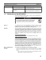
WARNING
Do not attempt to take the unit apart and do not touch any
internal parts while the power is being supplied. Doing either of
these may result in electrical shock.
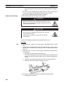
WARNING
Switch OFF the NT31/NT31C power before replacing the
backlight. Otherwise you could sustain an electric shock.
CAUTION
Do not touch the backlight immediately after switching OFF
the power supply.
Otherwise burn injuries may result due to the high
temperatures.
xvii
Safety Precautions
xviii
3
SECTION 1
General
This section provides fundamental information about the functions and features of the PTs, types of connection,
communications methods, etc. This information will enable you to understand the applications of the PTs.
1-1
1-2
1-3
1-4
1-5
1-6
Role and Operation of the NT31/NT31C . . . . . . . . . . . . . . . . . . . . . . . . . . . .
2
1-1-1
Operation of an NT31/NT31C at an FA Production Site. . . . . . . . .
2
1-1-2
Operations of the NT31/NT31C . . . . . . . . . . . . . . . . . . . . . . . . . . .
3
Functions of the NT31/NT31C. . . . . . . . . . . . . . . . . . . . . . . . . . . . . . . . . . . .
4
1-2-1
Features . . . . . . . . . . . . . . . . . . . . . . . . . . . . . . . . . . . . . . . . . . . . . .
4
1-2-2
Comparison between NT31 and NT31C . . . . . . . . . . . . . . . . . . . . .
6
1-2-3
Comparison between NT30/NT30C and NT31/NT31C . . . . . . . . .
7
1-2-4
Principal Functions of NT31/NT31C. . . . . . . . . . . . . . . . . . . . . . . .
8
1-2-5
Displays . . . . . . . . . . . . . . . . . . . . . . . . . . . . . . . . . . . . . . . . . . . . . .
10
System Configuration . . . . . . . . . . . . . . . . . . . . . . . . . . . . . . . . . . . . . . . . . . .
15
1-3-1
Peripheral Devices That Can Be Connected . . . . . . . . . . . . . . . . . .
15
1-3-2
Connecting to the Host. . . . . . . . . . . . . . . . . . . . . . . . . . . . . . . . . . .
16
Communications with the Host . . . . . . . . . . . . . . . . . . . . . . . . . . . . . . . . . . .
16
1-4-1
16
Direct Connection Function . . . . . . . . . . . . . . . . . . . . . . . . . . . . . . .
1-4-2
Host Link . . . . . . . . . . . . . . . . . . . . . . . . . . . . . . . . . . . . . . . . . . . . .
17
1-4-3
NT Link . . . . . . . . . . . . . . . . . . . . . . . . . . . . . . . . . . . . . . . . . . . . . .
17
1-4-4
Connecting to other Companies’ PLCs . . . . . . . . . . . . . . . . . . . . . .
19
Communications Using Memory Links . . . . . . . . . . . . . . . . . . . . . . . . . . . . .
19
1-5-1
Memory Link . . . . . . . . . . . . . . . . . . . . . . . . . . . . . . . . . . . . . . . . . .
19
1-5-2
Comparison between Direct Connection and Memory Link . . . . . .
20
1-5-3
Memory Link Online Transfer Function . . . . . . . . . . . . . . . . . . . . .
20
Before Operating . . . . . . . . . . . . . . . . . . . . . . . . . . . . . . . . . . . . . . . . . . . . . .
21
1
Section 1-1
Role and Operation of the NT31/NT31C
1-1
Role and Operation of the NT31/NT31C
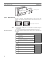
The NT31/NT31C is a sophisticated display unit (Programmable Terminal)
which automatically displays information and can also be used for operations
when necessary. The following gives a general description of the role and
operation of the NT31/NT31C for those using a programmable terminal (PT)
for the first time.
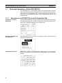
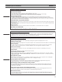
1-1-1
Operation of an NT31/NT31C at an FA Production Site
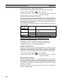
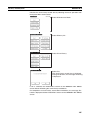
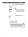
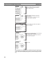
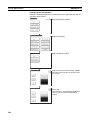
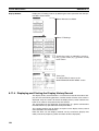
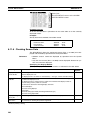
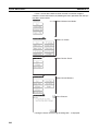
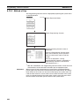
Production Line Status
Monitoring
The NT31/NT31C displays real-time information about the system and equipment operating status, etc. Its power of expression is enhanced by graphs and
other visuals, making the displays easy to understand.
Production Control (3)
Product
Today's target
Current production
Number defective
Number repaired
560
305
2
7
441
275
8
15
% achieved
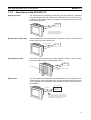
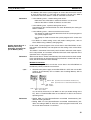
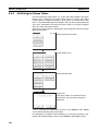
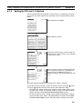
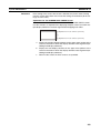
Directions to Workers on
the Shop Floor
The NT31/NT31C warns of system or equipment failures and prompts the
appropriate remedial action.
Alarm
Assembly line B
Positioning pin
is defective. Line stopped.
Check the following.
1. Defective pin L3
2. Position of dog M2
3. Mounting of photosensor P5
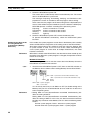
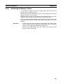
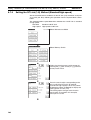
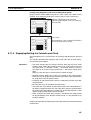
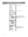
Panel Switch Functions
Setting touch switches on the NT31/NT31C allows workers to use the NT31/
NT31C as an operating panel; the results of the operations are transmitted to
the host.
Electroplating control
Transport
Electr.
head
Wash.
head
Corr. prv.
head
Electrolyte
Wash
Corr.
prv.fluid
Clamp
Unclamp
Adv.
Int. stop
Rev.
2
Section 1-1
Role and Operation of the NT31/NT31C
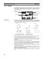
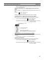
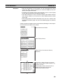
1-1-2
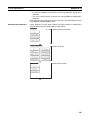
Operations of the NT31/NT31C
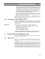
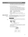
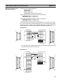
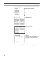
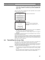
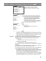
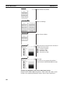
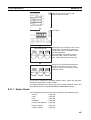
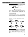
Displays Screens
The information to be displayed (screen data) can be created on a computer
using the Support Tool and stored in the NT31/NT31C. The screen data can
be displayed on the NT31/NT31C in response to instructions from the host or
touch switch operation.
Host
The screen data designated by
instructions from the host or touch
switch operation is displayed.
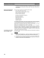
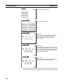
Receives Data from a Host
The NT31/NT31C can be connected to the host by a host link or NT link and
receive necessary data from the host.
Host link, NT link
Sends Data to a Host
Host
Data input using the touch panel (switch ON/OFF statuses, numeric values,
character strings) can be transmitted to the host.
Host
Touch panel
ON/OFF information, numeric
data, etc.
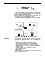
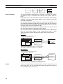
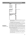
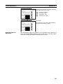
Screen Data
The screen data to be displayed on the NT31/NT31C can be created on a personal computer using the Support Tool. Connect the NT31/NT31C to the personal computer with an RS-232C cable and transmit the screen data to the
NT31/NT31C.
Create screen data.
RS-232C
Personal
computer
(Support Tool)
Screen data
When the host is connected at serial port A,
the personal computer is only connected
when communicating screen data between
the NT31/NT31C and Support Tool.
3
Section 1-2
Functions of the NT31/NT31C
1-2
Functions of the NT31/NT31C
The NT31/NT31C has the following features.
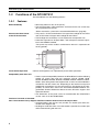
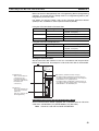
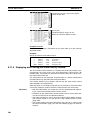
1-2-1
Features
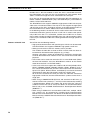
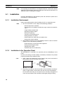
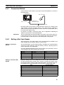
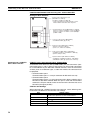
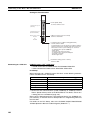
Downsized Body
• Slim body (50 mm or less in the panel*).
• The communications cable connectors are housed in the unit so that they
do not protrude from the unit.
*When mounted in a panel of the recommended thickness (page 30).
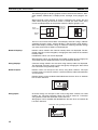
Construction Best Suited
to the FA Environment
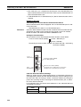
• The panel is an STN monochrome LCD type with backlight for the NT31
and an STN color LCD type with backlight for the NT31C.
• The backlight unit and battery can be replaced at the operation site.
• Protection equivalent to oil-proof IP65*, and waterproof structure equivalent to the NEMA4 standard.
*The panel may not be usable in environments where it is exposed to oil
for long periods.
320 dots
POWER
RUN
240 dots
Wide angle of visibility
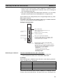
Touch Switch Operation
Contrast and brightness are adjustable by touch switch operations.
Compatibility with Other PTs
• There is upward compatibility between the NT31/NT31C and the following
models for screen data and user programs: NT11S, NT20S, NT30,
NT30C, NT600S, NT610G, NT610C, NT620S, NT620C, NT625C, NT631,
NT631. (After being read to the Support Tool, screens must be modified in
accordance with the screen size. Depending on the function used, partial
modification of programs may also be necessary. For details on the compatibility of screen data, refer to the NT31/NT31C/NT631/NT631C Programmable Terminal Reference Manual and the NT-series Support Tool
Operation Manual.
• The dimensions of the panel cut-out to accommodate the NT31/NT31C
are the same as for the NT30/NT30C.
Two Ports Featured as Standard:
Port A for Common Use by Support Tool/Host and Port B for Exclusive Use by the Host
• Communications with the host are possible via another port while connected to the Support Tool.
• Reading bar code data from a bar code reader is possible via another port
while communicating with the host.
4
Section 1-2
Functions of the NT31/NT31C
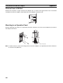
Rapid System Program & Screen Data Changes Possible Using a Memory Unit
• Installing a Memory Unit (model NT-MF261) on the rear of the NT31/
NT31C makes it easy to write screen data into the NT31/NT31C on site.
This enables a rapid response to setup changes.
• NT31/NT31C can store a system program into a Memory Unit. This
enables the system to handle more flexible setups.
Screen Data Check
Function
Screen data can be checked simply by operations at the NT31/NT31C system
menu, without connecting up to the Support Tool.
Increased Screen Data
Capacity
The data capacity of 1 MB is twice that of the NT30/NT30C, enabling storage
of a larger quantity of screen data.
Large Increase in
Maximum Number of
Registered Elements
The number of elements that can be registered on one screen has been considerably increased, making it possible to create more expressive screens.
For details, refer to Display Restrictions in Appendix A Specifications of the
NT31/NT31C/NT631/NT631C Programmable Terminal Reference Manual.
Binary Data can be Read
to/Written from the Host
It is now possible to write binary data stored in words at the host directly to the
NT31/NT31C. This makes data conversion by a program at the host unnecessary, reducing the load on the host.
Character Display Using
High Definition Fonts
Any quadrupled characters are displayed with a 32 dot high-definition font.
Simple Version Upgrades
By using the system installer supplied with the Support Tool (Type NTZJCAT1-EV4), the system program at the NT31/NT31C can be changed easily from a personal computer.
Complies with
International Standards
The NT31/NT31C meets UL/CSA standards and EC directives.
Compatible with Other
Vendors’ Devices
Compatible with Sequencers in the following series: Mitsubishi A-series (Calculator Link) and FX-series (Programming Console), Allen-Bradley SLC 500
Series, GE Fanuc 90-20 and 90-30 Series, and Siemens S7-300 and S7-400
Series. Specialized system programs can be installed that allow the NT31/
NT31C to be controlled from other companies’ Sequencers.
Multiple Windows
Up to 3 windows can be displayed simultaneously in the normal screen. A 9word window control area has been allocated to the host; the contents of
these 9 words can be changed from the Host to open, close, and move windows.
High-speed 1:N NT Link
The V2 versions are compatible with the high-speed 1:N NT Link as well as
the earlier standard 1:N NT Link.
Additional Mathematical
Functions
Operands (values referenced by formula) can be registered to allow the PT to
perform calculations automatically and write the results of those calculations
to numeral memory tables or words in the host.
Device Monitor Function
The new device monitor function can be used to change the PLC’s operating
mode or display/change values in the PLC’s memory areas. The present values (PVs) of several words can be listed with the device monitor.
Interlock Function
PT operations and inputs can be disabled from the PLC if interlock bits have
been allocated in the PLC for the corresponding PT touch switches, numeric
inputs, or string inputs.
Improved Lamp/Touch
Switch Labels
The following displays can be performed with lamp or touch switch labels:
• Display several lines of labels.
• Switch the display between different labels when OFF and ON.
5
Section 1-2
Functions of the NT31/NT31C
• Display the numeral memory table contents as labels.
• Display the string memory table contents as labels.
NT30/NT30C and NT620S/
NT620C/NT625C
Emulation
The word configuration of the PT status control area and PT status notify area
can be set to emulate those of the NT30/NT30C or NT620S/NT620C/
NT625C; this mode is called NT30/620 compatible mode.
When the PT is operating in NT30/620 compatible mode, it will be equivalent
to an NT30/NT30C or NT620S/NT620C/NT625C in the functions listed below.
The PT retains full V2 functionality in all functions other than the ones listed
below. Refer to Appendix C in the NT31/NT31C/NT631/NT631C Programmable Terminal Reference Manual for more details.
• Word configuration and functions of the PT status control area and PT
status notify area
• Image/library codes
• Insertion of image/library data into character strings
Additional CS/CJ-series
Data Areas Accessible
Data areas in CS/CJ-series PLCs that were previously inaccessible can be
accessed. The data areas listed below can be accessed (read/written).
All banks in the EM area, timer completion flags (TU), counter completion
flags (CU), Work areas (WR), Task flags (TK), and the HR area.
Recipe Function
You can set the data (numeric values) for multiple words in record units using
the tabular elements on the PT screen, and write these settings in a single
operation to words on the host (i.e., PLC or PT memory) using a touch switch
operation on the PT Unit. Also, multiple words of numeric data can be read
from the host in one operation. In this way, groups of parameter settings can
be edited at the PT Unit, and written to or read from the host.
Adjusting Contrast and
Brightness During PT
Operation
You can display the brightness and contrast adjustment screen using either
the touch switch or commands from the host, even while the PT is in operation.
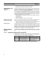
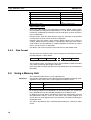
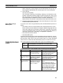
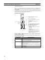
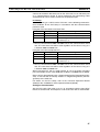
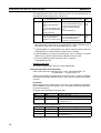
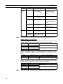
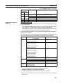
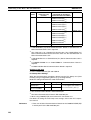
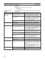
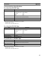
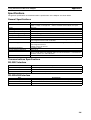
1-2-2
Comparison between NT31 and NT31C
Two NT31 models — the NT31, which is capable of versatile graphic displays,
and the NT31C, which is also capable of color display — are available. The
differences between the NT31 and NT31C are tabled below:
Function
Type
Display panel
NT31
NT31-ST123-EV3 (Beige)
NT31-ST123B-EV3 (Black)
STN monochrome LCD display
type (with white backlight)
NT31C
NT31C-ST143-EV3 (Beige)
NT31C-ST143B-EV3 (Black)
STN color LCD type
(with white backlight)
Beige and black are the front panel colors of each NT31/NT31C types.
6
Section 1-2
Functions of the NT31/NT31C
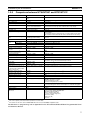
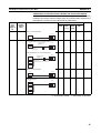
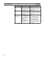
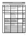
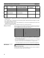
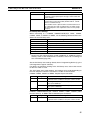
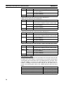
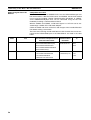
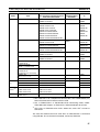
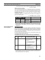
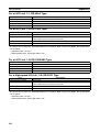
1-2-3
Comparison between NT30/NT30C and NT31/NT31C
Item
NT30/NT30C
NT31/NT31C
Support Tool used
NT-ZJCAT1-EV4 or NT-ZA3ATEV2
NT-ZJCAT1-EV4
DIP switches
On rear of PT
None (software settings)
Use of B7A Unit
Possible
Not possible
Use of Memory Unit
Not possible
Possible
RS-232C interface
Connector (9-pin) also used as
port for screen data transfer.
• Serial port A connector (also used for screen data transfer, 9-pin)
• Serial port B connector (for host communications only, 25-pin)
RS-422A/485 interface
Terminal block
Serial port B (25-pin D-SUB connector)
Backlight color
White/red (selectable)
White only
Replacement backlight
NT30-CFL01/NT30C-CFL01
NT31C-CFL01 (Same for both the NT31-ST121@-EV2 and NT31CST141@-EV2).
The backlight cannot be replaced by the user for the NT31-ST122@-EV2,
NT31C-ST142@-EV2, NT31-ST123@-EV3, and NT31C-ST143@-EV3.)
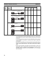
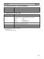
NT31/NT31C system program
data
NT-ZS3AT-EV1
(including system installer)
The system installer and system program data are supplied with the Support Tool.
High-speed 1:N NT Link
Not possible
Possible
Memory
Link
System program
Exclusive use by Memory Link
Same as OMRON connection
Screen data
Shared with OMRON connection Exclusive use by Memory Link
LCD contrast adjustment
By a control on the rear of the PT By touch panel operation
Backlight brightness adjustment
Not possible
By touch panel operation
Number of user-registered
screens
Maximum of 2000
Maximum of 3999
Screen data capacity*1
(User program memory)
512 KB
1 MB
Maximum of 2000
Numeral string data
Maximum of 1000
Character string data
Maximum of 1000
Maximum of 2000
Bit data
256
Maximum of 1000
Mathematical tables
None
256 max.
Calculations can be executed automatically in the PT.
Image data
Maximum of 224
Maximum of 4095*2
Library data
Maximum of 896
Maximum of 12288*2
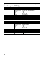
Method for storing numeric values
(numeral memory data and PT
status control area)
Fixed as BCD (binary coded dec- Selectable from BCD (binary coded decimal) or binary
imal)
PT status control area size
4 words
5 words (partial change of contents)*2
PT status notify area size
3 words
2 words (partial change of contents)*2
Window control area size
None
9 CH
Registering continuous screen
Possible
Not possible (Use a screen switchover as a substitute.)
Lamp/Touch switch labels
Fixed display (1 line only)
•
•
•
•
Interlock function
None
Operations can be disabled from the PLC by allocating interlock bits to
the corresponding touch switch, numeral input, or character string input.
Device monitor function
Not possible
Possible
Recipe function
None
Possible
Accessible CS/CJ-series PLC
data areas
---
The data areas listed below can be accessed in addition to the data
areas accessible with the NT30/NT30C.
• EM banks (EM_0 to EM_C)
• Timer completion flags (TU)
• Counter completion flags (CU)
• Work areas (WR)
• Task flags (TK)
• HR area
Multiple lines can be displayed
ON/OFF switching is possible
Numeral display is possible
Character string display is possible
*1
This is the capacity of the flash memory that stores screen data.
*2
The values are the same as the NT30/NT30C when the PT is in NT30/620 compatible mode.
For differences in programming, refer to Appendix B in the NT31/NT31C/NT631/NT631C Programmable Terminal Reference Manual.
7
Functions of the NT31/NT31C
1-2-4
Principal Functions of NT31/NT31C
The following are the principal functions of the NT31/NT31C.
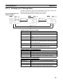
Functions relating to data display
Character display
Characters of various sizes can be displayed. Characters can be flashed and displayed in reverse
video. High grade fonts are available for the characters with their size enlarged.
Graphic display
Polylines, rectangles, polygons, circles, circular arcs, and sector shapes can be displayed. They
can also be tiled with various patterns, flashed, or displayed in reverse video.
Memory data display
The contents of character string memory tables and numeral memory tables can be displayed.
The contents of memory tables can be changed from the host.
Graph display
Not only bar graphs but also broken line graphs, trend graphs, and analogue meter graphs can be
displayed using numeral memory tables
Lamp display
Lamps can be turned on and flashed under the control of the host. It is also possible to display
different graphics in the ON and OFF states.
Alarm list/history display
Warning messages are automatically displayed in a list in response to the state of a host bit. The
time and the number of times of the messages appeared can also be displayed.
Functions relating to data output
Buzzer
A built-in buzzer can be sounded.
Screen printing
A hard copy of the currently displayed screen can be printed at the
printer connected to the NT31/NT31C.
8
Section 1-2
Functions of the NT31/NT31C
Section 1-2
Functions relating to data input
Input by touch switches
Data can be input by simply touching touch switches displayed on the screen.
The possible functions of touch switches include sending data to the host and changing the screen display.
Inputs can be enabled and disabled from the host when interlock bits have been allocated.
Pop-up window function
A window overlaying the currently displayed screen can be alternately opened and closed by pressing a touch switch.
In addition to fixed character and graphic displays, control keys and character keys created as touch switches can also be set
inside the window. A maximum of three windows can be displayed simultaneously. Since the window need only be opened when
input is required, the screen can be used efficiently.
Numeral/character string setting function
Numeric keys and character keys can be assigned to touch switches so that numeric values and character strings can be input at
the operation site.
The input data is written to numeral/character string memory tables and also sent to the host. It is also possible to disable input by
control from the host.
Recipe function
Several words of numeric data can be edited at the PT Unit, and written to or read from the host in one operation.
Input from a bar code reader
Data read with a bar code reader can be input to a character string input field.
Functions relating to communications
Communications with the host
The NT31/NT31C can communicate with the host by four methods: host link, 1:1 NT Link, 1:N NT link (standard or high-speed),
and Memory link. Data can be read from the host, and data input by means of touch switches and numeral/character string
settings can be sent to the host. It is also possible to connect with other model PLCs.
Functions relating to the system
System menu
System settings and maintenance can be performed by selecting from system menus displayed on the screen.
Creation of screen data
Screen data created using the Support Tool at a personal computer can be transferred and stored in the built-in screen data memory.
Resume function
The status and memory table contents of the NT31/NT31C immediately before its operation is stopped can be stored while
operation is stopped, or while the power is off, and then displayed on the screen again when operation is restarted.
Screen saver function
This function serves to extend the service life of the backlight and prevent the formation of an afterimage on the screen.
Clock function
The time can be displayed in accordance with the internal clock data.
Programming Console function
The PT can perform the same operations as a C200H-PR027-E Programming Console when the PT is connected to a CPM1,
CPM2A, CPM2C, CQM1, CQM1H, C200HX/HG/HE-(Z)E, or SRM1 PLC in a 1:1 NT Link connection, or a CS/CJ-series PLC in a
1:N NT Link connection.
Device Monitor function
When the PT is connected to a PLC in a 1:1 NT Link or 1:N NT Link, the PT can be used for operations such as changing the
PLC's operating mode, displaying or changing the PVs of words, or reading the error log.
System program install function
The system program of the NT31/NT31C can be changed by using the system installer supplied with the Support Tool
(NT-ZJ3AT1/ZJCAT-EV2). It can also be installed by using a memory unit (NT-MF261).
Screen display history function/alarm history function
The screen display history function records the time at which specific screens are displayed and the number of times they
are displayed. The alarm history function records the time at which specific bits at the host are turned ON and the number
of times they are turned ON.
Trend graph logging function and background function
Changes in the contents of numeral memory tables displayed in trend graphs can be recorded (logging function). Also, the
record can be maintained even when the trend graph is not displayed (background function).
Mathematical function
This function allows calculations to be executed continuously during PT operation when mathematical table has been set in
screen data. Arithmetic operations, bit operations, logic operations, and comparison operations can be performed. Operations
with up to 5 terms are possible.
9
Section 1-2
Functions of the NT31/NT31C
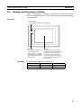
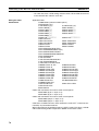
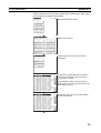
1-2-5
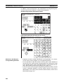
Displays
The NT31/NT31C can display various kinds of elements such as characters,
numeric values, graphs, lamps, and touch switches, on a screen. The screen
data displayed by the NT31/NT31C are created by using the Support Tool at a
personal computer.
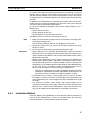
Characters
(fixed display)
Stop
Line 1 Status
Restart
Characters
(character string display)
Machine name: NT31C-ST143
Production qty.: 137 units
25%
Bar graph
0%
Stage 1
Fixed Displays
Check 1
50%
Stage 2
Touch switches
100%
Check 2
Numeric values
(numeral display)
Lamps
Characters and various graphics (circles, circular arcs, sectors, polylines,
polygons and rectangles) whose display does not have to be changed, and
mark data, image data, and library data that has already been registered, can
be written directly onto the screen.
Circle
Arc
Sector
Polyline
Polygon
Rectangle
* A continuous straight line with
up to 256 points can be drawn.
* A polygon with up to 255
vertices can be drawn.
Marks are graphics comprising 16 by 16 dots that can be used as characters.
They can be used as custom characters within character strings.
Image data are graphics comprising any required area of dots. They are registered in advance and as many as required can be displayed at any position on
the screen.
Windows bit map (BMP) data can be used for images.
There is a two-color mode, in which the display color and background color of
the image are specified when it is registered in a screen, and an eight-color
mode in which colors are assigned to the image in advance.
Since image data is composed of dots, it requires a large data size but offers
great powers of expression.
Library data are combinations of fixed display graphics registered as a single
graphic. They are registered in advance and as many as required can be displayed at any position on the screen.
Since it is generated by combining graphics, library data has a small data
size.
10
Section 1-2
Functions of the NT31/NT31C
Mark Image data Library data
Lamps
These are graphics whose display status changes in accordance with the
states of bits at the host. Squares, circles, sectors and polygons can be used
for lamps (normal (standard) lamps). In accordance with the status of the host
bit, they can be lit (displayed in reverse video) or flashed (repeated alternation
between normal and reverse video display states).
Lamps can also display different image/library data for the ON and OFF states
of the host bit (such lamps are called image/library lamps).
There are four standard lamp labels: fixed display character strings, ON/OFF
switching character strings, numeral displays, and character string displays.
When fixed display character strings or ON/OFF switching character strings
are used, several lines of labels can be displayed.
Normal (Standard) Lamps
ON
ON
Host
Unlit state
Lit state
Image Library Lamps
ON
Host
Unlit state
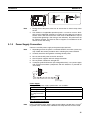
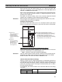
Touch Switches
Lit state
These switches can be set at any location on the screen. Pressing a touch
switch on the screen where a touch switch has been set can have the following effects:
• Notification to a host bit (input notification function)
• Changing the displayed screen (screen switching function)
• Input of a numeric value or character string (input key function)
• Copying of a numeric value or character string (copy key function)
• Shifting to another numeric value or character string input field (cursor
moving key function)
• Obtaining a hard copy of the screen (screen print function)
• Opening / Closing a window
• Moving a window
Touch switches can be made to light or flash in accordance with the status of
a host bit in the same way as lamps.
11
Section 1-2
Functions of the NT31/NT31C
The following 8 types of display graphic can be used for touch switches: Standard, shadow, 3-dimension, no display frame, rectangle, circle, polygon, sector
When rectangle, circle, polygon, or sector is selected as the shape, the area
within which pressing of the touch switch is sensed (the touch switch area)
can be set independently of the position where the display graphic is set.
When this
position is
pressed...
Touch
switch area
Shown
in
reverse
video
Display
frame
Function executed
There are four touch-switch labels: fixed display character strings, ON/OFF
switching character strings, numeral displays, and character string displays.
When fixed display character strings or ON/OFF switching character strings
are used, several lines of labels can be displayed.
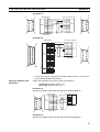
Numeral Displays
Numeric values stored in the numeral memory tables are displayed. The displayed numerals can be changed by changing the data stored in the numeral
memory tables.
Hexadecimal values can also be displayed.
When decimal values are displayed, the number of digits for the integral part
and fractional part of displayed values can be specified in advance.
String Displays
Character strings stored in the character string memory tables are displayed.
The displayed character strings can be changed by changing the data stored
in the character string memory tables.
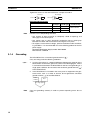
Numeral Inputs
Numeric values can be input at the PT by using touch switches. The input
numeric values can also be stored in a numeral memory table and notification
sent to the host.
Numeral inputs can be enabled and disabled from the host when an interlock
bit has been allocated.
12345678
7 8
4 5
1 2
0.
Input
9
6
3
±
Window
String Inputs
Character strings can be input at the PT by using touch switches, bar code
readers, etc. The input character strings can also be stored in a character
string memory table and notification sent to the host.
String inputs can be enabled and disabled from the host when an interlock bit
has been allocated.
Character string setting input field
Display
NT31C
Input
NT31C NT31
12
NT631C
Section 1-2
Functions of the NT31/NT31C
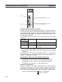
Thumbwheel Switches
Numeric values can be input by incrementing or decrementing each digit with
the corresponding touch switch (+, –). The input numeric values can also be
stored in a numeral memory table and notification sent to the host.
Thumbwheel switch inputs can be enabled and disabled from the host when
an interlock bit has been allocated.
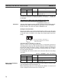
Graphs
These are graphics whose display changes in accordance with the numeric
values stored in numeral memory tables. There are the following four types.
Bar Graphs
Bar graphs display the present value in a numeral memory table converted to
a percentage within the range –100% to +100% of a preset value.
60%
Analog Meters
Analogue meters display, using a quarter, half, or full circle shape, the present
value in a numeral memory table converted to a percentage within the range –
100% to +100% of the preset value. Users can choose from moving pointer
type and filling area type displays. Users can also add graduation to the
graph.
60%
Broken Line Graphs
Broken line graphs display, in an easy-to-read form, a sequence of numeral
memory table values converted to a percentage within the range –100% to
+100% of a preset value.
100%
0%
*100%
Example showing a series of 11
numeral memory table values
(with a check mark set for the
display sign)
Trend Graphs
Trend graphs display chronological changes in the value in a numeral memory
table, converting the value to a percentage within the range –100% to +100%
of a preset value. The trend graph shifts position with the passage of time.
Past data can also be recorded, and the numeral memory table can be read
(sampled) even while the trend graph is not being displayed.
The user can choose to stop sampling, restart sampling, or display past data,
by pressing touch switches.
13
Section 1-2
Functions of the NT31/NT31C
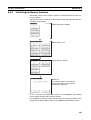
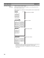
Alarm List/History
The alarm list/history function displays messages in list form, or graphics
(image/library data), in accordance with changes in bit memory table statuses.
For the alarm list, a series of bit memory tables are monitored, and messages
(contents of character string memory tables) set for bit memory tables that
come ON are displayed.
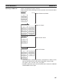
For the alarm history, bit memory tables for which the history property is set
are continually monitored, and the time when they come ON and number of
times they come ON are recorded and displayed together with the message
(character string) set for the bit memory table.
The NT31/NT31C allows selection of the display order as the newest record
first or the oldest record first by memory switch setting.
The alarm list function is used to determine which bits are ON at the present
time. The alarm history function is used to determine the times at which
alarms occurred in the past and how many times alarms have occurred.
Alarm List
Message (character string table No. 32)
set for bit memory table No. 14
Character string table No. 32
Character string table No. 50
Image/library data 1002
Character string table No. 32
Image/library data 113C
Image/library
data 113C
Character string table No. 54
Image/library data 1125
No.13
Bit
No.14
0
1
0
No.15
HOST
A000000
L001003
D010015
1(ON)
When the message displayed is pressed, the image/library
data (113C) set for bit memory table No. 14 is displayed.
Alarm History
Message (character string table No. 13)
set for bit memory table No. 24
Recorded data
Character string table No. 13
Character string table No. 12
Image/library
data 102B
Character string table No. 11 No. 22
Image/library data 005F
Bit memory table No. 24
97/12/04 11:19:20
Character string table No. 12 No. 23
Image/library data 102A
Bit memory table No. 23
97/12/04 11:25:12
Character string table No. 13
Image/library data 102B
No. 24
When the upper message displayed is pressed, the image/library
data (102B) set for bit memory table No. 13 is displayed.
Recipe
14
You can set several words of numeric data at the PT in tabular format, and
write it to the host. You can also read several words of numeric data from the
host and display it on the PT screen.
Section 1-3
System Configuration
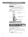
1-3
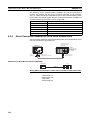
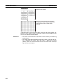
System Configuration
This section shows the configuration of a system that uses an NT31/NT31C.
For details on product models, refer to Appendix J Model List.
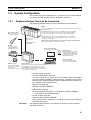
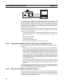
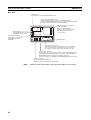
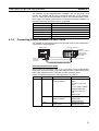
1-3-1
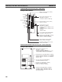
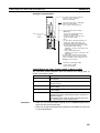
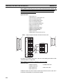
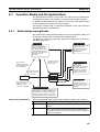
Peripheral Devices That Can Be Connected
The following peripheral devices can be connected to an NT31/NT31C.
Host
Controls the NT31/NT31C as required while controlling machines and monitoring
the production line.
Host Link: CS/CJ-series, C-series, and CVM1/CV-series PLCs, SRM1
Can be connected to CPU Units, Host Link Units, and SRM1. However,
connection is not possible to some models of CPU Unit and SRM1.
Bar code reader
Bar codes can be read
as character strings.
RS-232C cable
(max. 15 m)
or
RS-422A/485 cable
(max. 500 m)
NT Link: CS/CJ-series, C-series, and CVM1/CV-series PLCs, SRM1
Can be connected to CPU Units and SRM1. However, connection is not
possible to some models.
Memory Link: Can be connected to a personal computer, FA computer, etc.
Other companies' PLCs can also be connected.
Printer
For printing out the
currently displayed
NT31/NT31C screen.
Personal computer
Running Windows 95/98/NT
Support Tool
Used to create screens for the
NT31/NT31C at the personal
computer and transmit them to
the NT31/NT31C, and to make
NT31/NT31C settings.
System installer
Used to change the system
program of the NT31/NT31C.
Memory unit
NT31/NT31C
Can store screen data
and system program to
be read out
automatically at startup.
Displays production line monitoring and instructions
to the operation site, and notifies the host of the
switch ON/OFF status and numeric value inputs.
When a 1:N NT Link is being used, up to 8 PTs can
be connected to a single PLC.
• Bar code reader (page 34)
• Recommended printers (page 34)
It is also possible to use printers that can emulate an NEC PC-PR201H
(using the NEC PC-PR201PL control protocol), and printers that comply
with one of the following EPSON control standards: ESC/P 24-J83C (color), or ESC/P 24-J82 (monochrome).
• Memory Unit (page 36)
NT-MF261 (made by OMRON)
• Support Tool (page 33)
NT-series Support Tool Version 4.@ for Windows (Made by OMRON)
• NT-ZJCAT1-EV4 (CD-ROM version)
• System installer (page 33)
System installer (made by OMRON)
The system installer is supplied as a standard accessory with the Support
Tool (NTZJCAT1-EV4).
Reference:
The following optional devices are available. All of them can be used either
with NT31 or NT31C.
15
Section 1-4
Communications with the Host
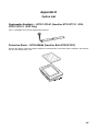
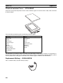
Reflection-suppressing protective sheet NT30-KBA04
1-3-2
Chemical-resistant cover
NT30-KBA01
Replacement battery
3G2A9-BAT08
Connecting to the Host
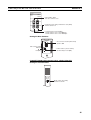
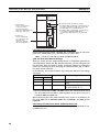
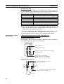
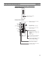
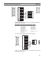
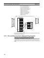
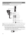
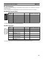
The NT31/NT31C has the following two communications ports.
• Serial port A:
• D-SUB 9-pin connector
• For RS-232C use only (The Support Tool and bar code readers can be
connected here.)
• Serial port B:
• D-SUB 25-pin connector
• For RS-232C or RS-422A/485 (Selectable by memory switch)
• (The Support Tool and bar code readers cannot be connected here.)
The host can be connected at either of these two ports.
The connection methods for each communications method at the PT and host
sides are indicated below. Make the settings in accordance with the communications method that can be used with the PLC to be connected and the conditions at the operation site.
Reference:
1-4
When using an RS-232C/422A Adapter (NT-AL001) with the host link or NT link
(1:1) communications method, RS-485 cannot be used. The connection must
be made with RS-232C or RS-422A.
Communications with the Host
The NT31/NT31C is connected to the host by one of the following communications methods.
The following communications can be used to connect an OMRON PLC:
• Host link
• 1:1 NT Link
• 1:N NT Link (standard or high-speed)
The following communications can be used to connect another companies’
PLC or FA computer:
• Communications protocol supported by the other company’s PLC
• Memory link
In all of these communications methods that can be used with NT31/NT31C,
data communications with host are by direct connection (Memory link is, however, a quasi-direct connection).
In the following, the host link and NT link that carry out the direct connection
will be discussed. Memory links will be explained in 1-5 Communications
Using Memory Links.
1-4-1
Direct Connection Function
With the NT31/NT31C, the bits and words referring to data required for display, and those for storing input data, can be allocated to any part of the PLC
memory area.
16
Section 1-4
Communications with the Host
The NT31/NT31C can directly write to and read from such allocated bits and
words to change the display status of the elements on the PT screen, control
the PT operating status, and notify the host of the status.
This function, which directly reads and writes the statuses of words and bits
without using a PLC program is called the direct connection function.
The words and bits allocated for direct connection are called the allocated
words and allocated bits.
The direct connection function allows the data to be displayed at the NT31/
NT31C to be read from the memory area in the PLC and written to memory
tables in the NT31/NT31C. Also, the data input at the NT31/NT31C can be
written to the memory area in the PLC. The NT31/NT31C screen can be
changed in accordance with statuses in the PLC memory area, and the NT31/
NT31C’s status data can be written to the PLC’s memory area.
NT31/NT31C
PLC
DM area
I/O relay area
Auxiliary relay area Timers/counters
Features of the Direct
Connection Function
The direct connection function has the following features.
• The bits and words referring to operating status and work instruction information and those for storing input data can be freely allocated to almost
any area of the PLC memory.
• Since the NT31/NT31C can directly refer to PLC bit and word data without
using the program at the PLC, it can be connected to the PLC without
changing the PLC program which controls the currently running production line.
• The area to control and provide notification of NT31/NT31C status, including display screens, display/no display status, and buzzer output, can be
freely allocated to any part of the PLC data area. This means that the
PLC status can be read and controlled just by reading this area at the
PLC side, without preparing a special communications program.
The direct connection function allows the NT31/NT31C to directly read and
write almost all bits and words in the PLC and to automatically change the
NT31/NT31C screen display. This function can reduce the load on the PLC so
that its program development efficiency is improved.
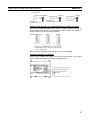
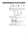
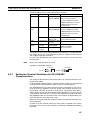
1-4-2
Host Link
The host is connected to a PT in a 1:1 connection, and the words and bits of
the host are read and displayed by host link communications. This method
can be used for connection to the majority of PLC types.
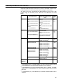
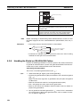
1-4-3
NT Link
NT link is a method for high-speed communications with a PLC using the
direct connection function. The PLCs that can be connected with the NT link
are as follows.
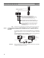
• When using the built-in host link function of a CPU Unit or SRM1:
CPM1, CPM2A, CPM2C, CQM1, CQM1H, C200HS, C200HX/HG/HE(Z)E, CS1G/CS1H-E(V1), CS1D, CJ1G/CJ1H/CJ1M, CVM1/CV-series
PLC (-EV1 or later version), SRM1
17
Section 1-4
Communications with the Host
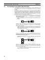
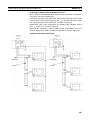
Besides the 1:1 NT Link method, in which one PLC is connected to one PT,
the NT31/NT31C can also use the 1:N connection NT Link method, which
allows a maximum of eight PTs to be connected to one PLC port.
PLCs that can be connected with the 1:N connection NT Link method are as
follows: CQM1H, C200HX/HG/HE (-Z)E, CS1G/CS1H-E(V1), CS1G/CS1H-H
CS1D, CJ1G/CJ1H/CJ1M PLCs.
The NT31/NT31C also supports OMRON’s high-speed 1:N NT Link that provides faster 1:N communications. The only PLCs that support the high-speed
1:N NT Link are the -EV1 and higher versions or the high-speed versions of
the CS1G/CS1H PLCs and the CS1D and CJ1G/CJ1H/CJ1M PLCs.
In the following sections, the term NT Link is used to refer to the NT Link communications method in general, the term 1:1 NT Link is used to refer specifically to NT Links with a 1:1 connection, and the term 1:N NT Link is used to
refer to both standard and high speed NT Links with 1:N connections. When
necessary, the standard 1:N NT Link is distinguished from the high-speed 1:N
NT Link.
Features of the NT Link
The NT link has the following features.
• High-speed communications with specific types of PLCs can be executed.
The NT31/NT31C also supports OMRON’s high-speed 1:N NT Link.
• Writing in units of bits to the PLC memory area is possible.
This enables the other bits of words to which a touch switch has been allocated to be allocated for other purposes (e.g. a lamp).
However, since data is written to the DM area in word units, the other bits
of words allocated to touch switches in this area cannot be used for other
purposes.
• The NT link can be used even when the PLC is in the RUN mode. (When
the host link method is used, the NT31/NT31C switches to the monitor
mode when the PLC is in the RUN mode.)
• In the case of PTs that support the standard 1:N NT Link (NT20S, NT31,
NT31C, NT600S, NT620S, NT620C, NT625C, NT631, NT631C) up to 8
PTs can be connected to one port of the PLC and used at the same time.
Up to 8 PTs (NT31, NT31C, NT631, and NT631C) can also be connected
simultaneously when the high-speed 1:N NT Link is being used.
All of the PTs connected to a PLC port must use either the standard or
high-speed 1:N NT Link; the two communications systems cannot share a
single port.
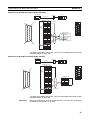
• When using a C200HX/HG/HE-(Z)E PLC and standard 1:N NT Links, up
to three 1:N NT Link systems (i.e., 24 PTs) can be connected by installing
a Communications Board in the option slot of the CPU Unit. (Only the
standard 1:N NT Link can be used.) For details on the Communications
Board, refer to the SYSMAC Communications Board Operation Manual
(W304-E1-@).
• When using a CQM1H PLC and standard 1:N NT Links, multiple 1:N NT
Link systems can be connected by installing Serial Communications
Boards in the Inner Board slots. For details on the Serial Communications
Board, refer to the CQM1H Serial Communications Board Operation Manual (W365-E1-@).
18
Communications Using Memory Links
Section 1-5
• Multiple 1:N NT Link systems (standard or high-speed) can be connected
by installing a Communications Board in the Inner Board slot of the CPU
Unit for a CS1G/H/D PLC or installing a Serial Communications Unit on
the Backplane for a CS1G/H/D or a CJ1G/M/H PLC. For details on the
Communications Board/Communications Unit, refer to the CS/CJ-series
Serial Communications Board/Unit Operation Manual (W336-E1-@).
• If the PLC used supports the Programming Console function, the NT31/
NT31C can be used as a Programming Console.
• If the PLC being used supports the Device Monitor function, the NT31/
NT31C can be used to change the PLC’s operating mode and read/
change data in the PLC’s memory areas.
The NT link is compatible with the host link. The NT31/NT31C screen data
and PLC programs used with the host link direct connection method can be
used with the NT link method as they are.
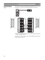
1-4-4
Connecting to other Companies’ PLCs
Installing a system program for multi-venders by using a specific system
installer enables the NT31/NT31C to be connected to the PLCs of other models in direct connection. This system installer is supplied with the Support Tool
(NT-ZJCAT1-EV4).
Compatible PLC
The NT31/NT31C can be connected to the following model PLCs.
• Mitsubishi A series programmable controller (computer link module)
• Mitsubishi FX series programmable controller
• SLC 500 Series by Allen-Bradley
• 90-20 and 90-30 Series by GE Fanuc
• S7-300 and S7-400 Series by Siemens
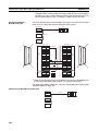
For details on the procedure for connecting to other model PLCs, refer to the
PLC Connection Manual or NT31/631 Multi Vendor Connection Manual.
1-5
Communications Using Memory Links
In this section, a communications method other than the direct connection,
called the memory link, is discussed.
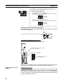
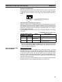
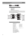
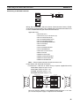
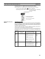
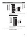
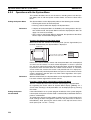
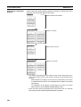
1-5-1
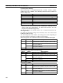
Memory Link
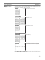
Memory link is a method to send and receive data between a personal computer or a FA computer and the NT31/NT31C by using RS-232C/422A communications.
In memory link, there is an area called PT Memory, as shown below, inside
the NT31/NT31C, and this area is treated as a virtual area on the PLC. This
allows PT memory and the display elements of the NT31/NT31C to make a
quasi-direct connection. By sending a command for the memory link, the host
can make the NT31/NT31C execute processes through PT memory. Frequently used commands are kept handy for read and write tasks of the
numeral memory table, character-string memory table, and bit memory table.
19
Section 1-5
Communications Using Memory Links
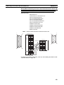
NT31/NT31C
PT
PLC
PT memory
Numeral
memory
table
Lamp
Direct connection
RS-232C/422A
communications
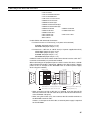
In the memory link method, the only difference is that the NT31/NT31C finds
its communications target inside instead of outside. In the memory link
method, therefore, change of the target is all that is needed to be capable of
using the exact screen data that is acquired by the direct connection. (With
the NT31/NT31C, the Support Tool must be used to convert the data to
screen data for the memory link.)
When compared to the direct connection of the host link or NT link methods,
the memory link method has some restrictions regarding the use of some
functions, as described below.
• The Programming Console and Device Monitor functions cannot be used.
• The following strobes of PT status notify bits do not turn ON (page 7 to
27).
Screen switching strobe
Numerals input strobe
Character-string input strobe
• The usable area for allocation is the PT memory only.
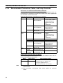
1-5-2
Comparison between Direct Connection and Memory Link
The major differences between the direct connection and the memory link are
as follows:
• In the memory link method, the communications with the host should be
carried out by using commands. Compared to the ordinal direct connection, which can be used requiring almost no programs, the memory link
method requires a program that is necessary for interchange of commands. This, however, gives advantages to the memory link method by
using a large variety of functions available in the direct connections from
major models such as a personal computer and a FA computer equipped
with RS-232C/RS-422A communications means, allowing the PT to be
suited for larger usage.
• Actual PLCs have many kinds of areas, where as PT memory is a single
area with only one kind. When creating screen data by using the memory
link methods, it is always necessary to allocate display parts in the PT
memory.
For communications between the host and the PT by the memory link method
and for handling screen display elements, refer to the NT31/NT31C/NT631/
NT631C Programmable Terminal Reference Manual.
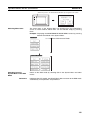
1-5-3
Memory Link Online Transfer Function
When memory link communications are being used, the NT31/NT31C can be
switched to Transmit mode from the host even if the NT31/NT31C is operating
and screen data can be written. (The NT31/NT31C can be returned to RUN
mode after the screen data is written.)
20
Section 1-6
Before Operating
The memory link online transfer function can be used to replace screen data
at a fixed time each day or replace screen data with maintenance screen data
for maintenance.
For more details on the memory link online transfer function, refer to information on the memory link online transfer function in the NT31/NT31C/NT631/
NT631C Programmable Terminal Reference Manual.
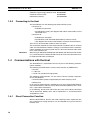
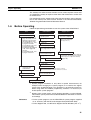
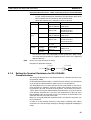
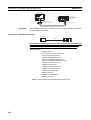
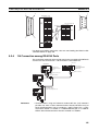
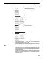
1-6
Before Operating
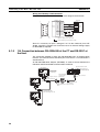
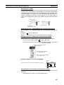
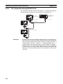
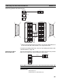
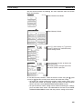
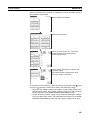
Follow the procedure given below to start the system of the NT31/NT31C.
Host
Support Tool
NT31/NT31C
Set the host settings.
• For the host link, refer to
pages 46 and 96, and the
manuals for the host link
unit and peripheral tools.
• For the NT link (1:1), refer
to pages 61 and 107.
• For the NT link (1:N), refer
to pages 64 and 109.
• For the high-speed NT link
(1:N), refer to pages 69
and 113.
• For the Memory link, refer
to pages 72 and 115.
Install the PT in the
operation panel.
Install the Support
Tool at the computer.
(page 30)
Connect the power supply.
(page 31)
(Refer to the manual for
the Support Tool.)
Install the system program.*1
(Refer to page 151 and
the Support Tool manual.)
Make the settings in the
system installer mode.*2
(page 151)
Transmit the screen data.
Create the screens.
(Refer to the NT31/NT31C/NT631/NT631C
Programmable Terminal Reference Manual
and the Support Tool Operation Manual.)
(page 155)
Set the memory switches.
(page 158)
Connect to the host.
Connect to the
NT31/NT31C.
When RS-232C used at the PT: refer to section 4
When RS-422A/485 used at the PT: refer to section 5
Create the host program.
Confirm the settings and
check communications.
Start operation.
Reference:
*1
System program installation is only done in special circumstances, for
example when changing the system program, or to recover the original
status of the installed program. This operation is not normally necessary.
When using other PLC models (sequencers), however, it is necessary to
install specific system programs.
*2
Display of the system menu, and all change operations, can be inhibited.
This enables you to prevent the accidental deletion or alteration of screens
and settings.
• For the system program, use the NT31/NT31C system program supplied
as an accessory with the NT-series Support Tool (NT-ZJCAT1-EV4).
• For the Support Tool, use NT-series Support Tool for Windows (Ver. 4.@).
21
Section 1-6
Before Operating
Refer to the following manuals for the devices and software.
Device or Software
NT31/NT31C, NT631/
NT631C
System Installer
Support Tool
PLC
CompoBus Master
Control Unit
Programming
Devices
Host Link Unit/
Serial Communications Board
22
Manual Title
Reference Manual
NT-series Support Tool for Windows (Ver. 4.@) Operation Manual
NT-series Support Tool for Windows (Ver. 4.@) Operation Manual
SYSMAC CPM1 Operation Manual
SYSMAC CPM1A Operation Manual
SYSMAC CPM2A Operation Manual
SYSMAC CPM1/CPM1A/CAM2A/CPM2C/SRM1(-V2)
Programmable Controllers Programming Manual
SYSMAC CPM2C Operation Manual
SYSMAC C200H Operation Manual (for CPU01/03/11) (programming)
SYSMAC C200H Operation Manual (for CPU21/23/31) (programming)
SYSMAC C200HS Installation Guide
SYSMAC C200HS Operation Manual (programming)
SYSMAC C200HX/HG/HE-Z Installation Guide
SYSMAC C200HX/HG/HE Programming Manual
SYSMAC C200HX/HG/HE-Z Programming Manual
SYSMAC C1000H/C2000H Operation Manual (programming)
SYSMAC CQM1 Programming Manual
SYSMAC CQM1H Operation Manual
SYSMAC CVM1/CV500/CV1000/CV2000 Operation Manual: Ladder Diagrams
SYSMAC CS Series Programmable Controllers Operation Manual
SYSMAC CJ Series Programmable Controllers Operation Manual
SYSMAC CS Series, CJ Series, NSJ Series Programmable Controllers
Programming Manual
SYSMAC CS Series, CJ Series, NSJ Series Programmable Controllers
Operation Manual
SYSMAC CS/CJ Series Programming Consoles Operation Manual
SYSMAC CS/CJ/CP Series, NSJ Series Communications Commands
Reference Manual
SYSMAC CS/CJ Series Serial Communications Boards,
Serial Communications Units Operation Manual
SYSMAC CQM1H Series Serial Communications Board Operation Manual
SRM1 Operation Manual
SYSMAC Support Software Operation Manual: C-series PLCs
SYSMAC Support Software Operation Manual: CVM1 PLCs
SYSMAC CPT User Manual and Quick Start Guide
CX-Programmer Operation Manual
SYSMAC C-series Host Link Unit Operation Manual
SYSMAC CVM1/CV-series Host Link Operation Manual
SYSMAC C200HW-COM01 C200HW-COM02-V1 to C200HW-COM06-EV1
Serial Communications Board Operation Manual
Manual Number
V064-E1-1
V061-E1-05
V061-E1-05
W262-E1-@
W317-E1-@
W352-E1-@
W353-E1-@
W356-E1-@
W130-E1-@
W217-E1-@
W236-E1-@
W235-E1-@
W302-E1-@
W303-E1-@
W322-E1-@
W140-E1-@
W228-E1-@
W363-E1-@
W202-E1-@
W339-E1-@
W393-E1-@
W394-E1-@
W340-E1-@
W341-E1-@
W342-E1-@
W336-E1-@
W365-E1-@
W318-E1-@
W248-E1-@
W249-E1-@
W332-E1-@
W333-E1-@
W446-E1-@
W143-E1-@
W205-E1-@
W304-E1-@
SECTION 2
Preparing for Connection
This section describes the connection methods that are possible with the PTs, and the functions of the parts of PTs, as
the required knowledge before connecting to the host and to the peripheral devices.
2-1
Method for Connection to the Host . . . . . . . . . . . . . . . . . . . . . . . . . . . . . . . .
24
2-2
Names and Functions of Parts . . . . . . . . . . . . . . . . . . . . . . . . . . . . . . . . . . . .
27
23
Section 2-1
Method for Connection to the Host
2-1
Method for Connection to the Host
This section describes the methods for connection to the host used with the
NT31/NT31C, and the relationship between the connection method and the
communications method.
NT31/NT31C Communications Ports and Communications Methods
The NT31/NT31C has two communications ports. Their uses are indicated in
the table below.
Communications Usable communications methods Communications type
port
Serial port A
Host link
RS-232C
NT link (1:1)
Serial port B
NT link (1:N)(*1)
Memory link
(Support Tool connection)
(bar code reader input function)
Host link
NT link (1:1)
NT link (1:N)(*1)
Memory link
RS-232C
RS-422A/485
(select between RS-232C
and RS-422A/485)
*1: There are two NT Link (1:N) communications rates: standard and highspeed.
Communications Methods That Can Be Used with the Host
The following communications methods can be used with the hosts that can
be connected to the NT31/NT31C.
• RS-232C
• RS-422A
• RS-485
The communications types that are actually supported differ depending on the
host unit. For details, refer to SECTION 4 Connecting to the Host from the RS232C Port and SECTION 5 Connecting to the Host from the RS-422A/485
Port.
Converting the Communications Type with an RS-232C/RS-422A Adapter
The following communications type conversions are possible by using an RS232C/RS-422A Adapter (NT-AL001-E, made by OMRON).
• RS-232C ⇔ RS-422A
• RS-232C ⇔ RS-485
24
Section 2-1
Method for Connection to the Host
Combinations of Communications Method and Connection Method
The connection methods that can be used depending on the communications
method used and the communications type for communications between the
NT31/NT31C and the host are indicated in the table below.
Commu- Communinicacations
tions
Type at
Type at
Host
PT
RS-232C RS-232C
Usable Connection Method
Usable Communications Method
Host
NT
NT
Memory
link
Link
Link
link
(1:1)
(1:N)
Direct 1:1 connection
PT
Details
❍
❍
❍
❍
page 73
❍
❍
❍
❍
page 82
×
×
❍
×
page 86
❍
❍
❍
❍
page 116
×
×
❍
×
page 121
Host
RS-232C (max. 15 m)
RS-422A
RS-232C
1:1 connection via a convertor unit
Convertor unit
(NT-AL001)
PT
RS-422A
(max. 500 m)
Host
RS-232C
(max. 2 m)
1:N connection via a convertor unit
Host
PT
Convertor unit
(NT-AL001)
RS-232C
RS-422A
(total length 500 m) (max. 2 m)
RS-422A
Direct 1:1 connection
PT
Host
RS-422A (max. 500 m)
1:N connection
Host
PT
RS-422A (total length 500 m)
❍: Connection possible
×: Connection not possible
25
Section 2-1
Method for Connection to the Host
Commu- Communicanications
tions
Type at
Type at
Host
PT
RS-485 RS-232C
Usable Connection Method
Usable Communications Method
Host NT Link NT Link Memory
link
(1:1)
(1:N)
link
1:1 connection via a convertor unit
PT
Convertor unit
(NT-AL001)
RS-485
(max. 500 m)
×
×
❍
×
page 82
×
×
❍
×
page 86
×
×
❍
×
page 119
×
×
❍
×
page 124
Host
RS-232C
(max. 2 m)
1:N connection via a convertor unit
PT
Details
Convertor unit
(NT-AL001)
Host
RS232C
RS-485
(total length 500 m) (max. 2 m)
RS-485
Direct 1:1 connection
PT
Host
RS-485 (max. 500 m)
1:N connection
PT
Host
RS-485 (total length 500 m)
❍: Connection possible
×: Connection not possible
• The RS-232C/RS-422A Adapter (NT-AL001) requires +5 V, 150 mA at pin
6 of the RS-232C connector. Check the signals of the RS-232C connector
at the host.
• +5 V is not output from serial port B of the NT31/NT31C. When connecting an NT-AL001 at serial port B, a separate power supply is required for
the NT-AL001.
• The cable of an NT-AL001 cannot be connected or disconnected while the
power is ON. Always connect or disconnect the cable while the power
supply from the RS-232C cable is OFF (while the host power supply is
OFF).
• NT link (1:N) connection is possible even when RS-232C is used at the
NT31/NT31C side for communications with the host, but in this case one
NT-AL001 Adapter is required for each NT31/NT31C. In this case, it is
convenient to use serial port A of the NT31/NT31C. +5 V is not output
from serial port B.
26
Section 2-2
Names and Functions of Parts
2-2
Names and Functions of Parts
Before starting operation, the names and functions of the parts of the NT31/
NT31C are described here as a confirmation. A method of hardware settings
is also described.
Front View
POWER LED
Lit in green when the power is supplied.
POWER
RUN
RUN LED
• Lit in green while the unit
is in the RUN mode.
• Lit in orange or red when
the battery is low (orange
in the RUN mode, red in
other modes).
Reference:
Display
The NT31 has a monochrome
LCD screen with a backlight, and
the NT31C has an STN color
LCD screen with a backlight.
The whole area of the screen is a
touch panel which works as an
input device.
The NT31/NT31C comes in two body colors.
NT31
NT31-ST123-EV3
NT31-ST123B-EV3
NT31C
NT31C-ST143-EV3
NT31C-ST143B-EV3
Body Color
Beige
Black
27
Section 2-2
Names and Functions of Parts
Rear View
Battery cover
The battery is secured underneath this cover.
Reset switch (inside the cover)
Used to initializes all the statuses of the NT31/NT31C.
However, registered data such as screen data, and memory switch
settings, retain their statuses before initialization.
Expansion interface connector
(under the label)
GR terminal
Grounding terminal to prevent
malfunction due to noise.
When using an expansion
interface unit such as a memory
unit, peel off the label and
connect it here.
24V
DC
PRINTER
Power input terminals
Connect the power to the
NT31/NT31C at these
terminals.
PORT B
PORT A
Warning label
Serial port A connector
Connect the cable for connection to the host or Support
Tool here. A bar code reader can also be connected
here. This is a 9-pin connector for RS-232C use only.
Serial port B connector
Connect the cable for connection to the host here. Depending on the
setting made at the NT31/NT31C system menu, either RS-232C or
RS-422A/485 may be used. This is a 25-pin connector.
It is not possible to use RS-232C and RS-422A/485 at the same time.
Printer connector
Connect the printer cable here.
Output conforms to Centronics specifications.
Note
28
Confirm system safety before turning the power ON/OFF or resetting.
SECTION 3
Hardware Settings and Connections
This section describes the settings of the PTs and methods for connection to peripheral devices.
For details on connecting to the host, refer SECTION 4 Connecting to the Host from the RS-232C Port or SECTION 5
Connecting to the Host from the RS-422A/485 Port.
3-1
Installation . . . . . . . . . . . . . . . . . . . . . . . . . . . . . . . . . . . . . . . . . . . . . . . . . . .
30
3-1-1
Installation Environment . . . . . . . . . . . . . . . . . . . . . . . . . . . . . . . . .
30
3-1-2
Installation in the Operation Panel. . . . . . . . . . . . . . . . . . . . . . . . . .
30
3-1-3
Power Supply Connection . . . . . . . . . . . . . . . . . . . . . . . . . . . . . . . .
31
3-1-4
Grounding . . . . . . . . . . . . . . . . . . . . . . . . . . . . . . . . . . . . . . . . . . . .
32
3-2
Connecting to the Support Tool . . . . . . . . . . . . . . . . . . . . . . . . . . . . . . . . . . .
33
3-3
Connecting a Printer . . . . . . . . . . . . . . . . . . . . . . . . . . . . . . . . . . . . . . . . . . . .
34
3-3-1
Connection Method . . . . . . . . . . . . . . . . . . . . . . . . . . . . . . . . . . . . .
34
Connecting a Bar Code Reader . . . . . . . . . . . . . . . . . . . . . . . . . . . . . . . . . . .
34
3-4
3-5
3-4-1
Connection Method . . . . . . . . . . . . . . . . . . . . . . . . . . . . . . . . . . . . .
35
3-4-2
Setting a Bar Code Reader . . . . . . . . . . . . . . . . . . . . . . . . . . . . . . . .
35
3-4-3
Data Format . . . . . . . . . . . . . . . . . . . . . . . . . . . . . . . . . . . . . . . . . . .
36
Using a Memory Unit. . . . . . . . . . . . . . . . . . . . . . . . . . . . . . . . . . . . . . . . . . .
36
3-5-1
Installation Method . . . . . . . . . . . . . . . . . . . . . . . . . . . . . . . . . . . . .
37
3-5-2
Method of Use . . . . . . . . . . . . . . . . . . . . . . . . . . . . . . . . . . . . . . . . .
38
29
Section 3-1
Installation
Note
3-1
On unpacking the NT31/NT31C and peripheral devices, check their external
appearance and confirm that there is no damage. Also confirm that there is no
abnormal noise on shaking the PT lightly.
Installation
Install the NT31/NT31C in the operation panel and connect the power to the
NT31/NT31C as described below.
3-1-1
Installation Environment
Observe the following points when installing the PT in an operation panel.
Note
1. Do not install the PT at sites subject to the following conditions.
• Severe temperature variations
• Temperatures or humidities outside the ranges stated in the specifications
• High humidity, condensation
• Splashing chemical agents
• Severe oil splashing
• Corrosive or flammable gases
• Strong vibrations or shocks
• Direct exposure to wind and rain (outdoor sites)
• Strong ultra-violet irradiation
2. Take adequate measures to ensure shielding if the PT is used at a location
subject to any of the following conditions.
• Static electricity, or noise from other equipment
• Strong electromagnetic fields
• Nearby power cables
• Potential exposure to radioactivity
3-1-2
Installation in the Operation Panel
The NT31/NT31C is mounted in an operation panel by embedding it in the
panel.
Use the panel fittings and tool (Phillips screwdriver) included in the product
package and follow the procedure below.
1,2,3...
1. Open a hole of the dimensions shown below in the panel and install the
NT31/NT31C from the front side of the panel.
mm
131 +0.50 mm
mm
184 +0.50 mm
2. Attach the panel fittings at the four positions at top and bottom and two positions at right and left, shown below, from the rear of the NT31/NT31C.
Fit the hook of the fitting in the square hole in the body and tighten the
screw with the Phillips head screwdriver while lightly pulling the fitting.
30
Section 3-1
Installation
24V
DC
PRINTER
Note
PORT B
PORT A
1. During work at the panel, take care to ensure that no metal scraps enter
the PT.
2. The thickness of applicable operation panel is 1.6 mm to 4.8 mm. All fittings must be tightened uniformly to a torque of 0.5 to 0.6 N⋅m in order to
ensure water- and dust-resistance. Front sheet of NT31/NT31C may be
warped if the tightening is too strong or not uniformity. The panel must not
be soiled or warped, and must be able to support an installation that will
remain secure and strong.
3-1-3
Power Supply Connection
Connect a 24 VDC power supply to the power input terminals.
Note
1. Depending on how the power is switched ON/OFF, the entire system may
stop. Follow the correct procedure when switching the power ON/OFF.
2. Carefully check the wiring before switching ON the power.
3. Do not connect AC power to the DC terminals.
4. Use DC power supplies with low voltage fluctuation.
5. Do not perform a dielectric strength test.
6. If complying with EC directives (low voltage directives), use a power supply
with reinforced insulation (compliance with EC directives is planned for
June 1998).
24 VDC
Breaker
24 VDC
power supply
Power Supply
The applicable power supply specifications are as follows.
Item
Power supply
Allowable power supply voltage fluctuation
range
Power supply voltage
capacity
Value
24 VDC
20.4 VDC to 26.4 VDC (24 VDC –15%, +10%)
15 W or more
Parts Used for Connection
Note
For the connection to the power supply terminal block, twisted wires of 2 mm2
or greater cross sectional area and M3.5 size crimp terminals must be used.
31
Section 3-1
Installation
Tighten the screws on the terminal block to a torque of 0.8 N⋅m.
Fork type
Round type
7 mm max.
7 mm max.
Recommended Terminals
Maker
Japan Solderless Terminal MFG
Fuji Terminal
Nichifu Terminal
Note
Type
Type
Applicable Wire
(fork type) (round type) (stranded wire)
2-YS3A
2-3.5
2.0 to 2.63 mm2
2-YAS3.5
V2-S3.5
2Y-3.5
2-3.5
Conformance to Shipbuilding Standard
• Use gaskets or other materials to completely shield all openings and
other gaps in the control panel.
• Use copper tape or other electrically conductive tape to shield gaps
between the cutout and the PT before securing the PT in place.
• To suppress noise terminal voltage, perform installation under the following conditions. It is recommended to use the following product for the DC
power supply.
Recommended Power Supply model: S82K-03024
Manufacturer: OMRON
3-1-4
Grounding
The NT31/NT31C has a functional ground terminal (
).
Carry out wiring under the following conditions.
1,2,3...
1. In cases where there is a potential difference between the grounds of the
NT31/NT31C and the host, ground as shown in the following figure. If there
is some distance between the NT31/NT31C and host and grounding at a
single point is difficult, do not connect the functional ground terminal ( )
of the NT31/NT31C.
2. If the NT31/NT31C is installed in the same panel as equipment that generates noise, such as a motor or inverter, do not ground the functional
ground terminal ( ) of the NT31/NT31C.
NT31/
NT31C
Host
Grounding at
a single point
Note
32
Carry out grounding correctly in order to prevent operating errors due to
noise.
Section 3-2
Connecting to the Support Tool
3-2
Connecting to the Support Tool
In order to install the system program in the NT31/NT31C, or to transmit
screen data created with the Support Tool to the NT31/NT31C, the NT31/
NT31C must be connected to a personal computer with an RS-232C cable.
The NT31/NT31C connects the RS-232C cable from a personal computer at
serial port A. When the host is connected at serial port B, the connection with
the host can be maintained as it is while the NT31/NT31C is connected to the
RS-232C cable from a personal computer.
However, when a bar code reader is being used, it must be disconnected, so
that the RS-232C cable can be connected, since they both use serial port A.
PRINTER
PORT B
PORT A
Serial port A
(RS-232C, 9-pin)
Communications Conditions
The communications conditions are automatically set when the system
installer and Support Tool are started.
Recommended Connector Cable
Use the cable indicated below.
• CV500-CN228 (length: 2 m), made by OMRON
(D-SUB 9-pin, male ⇔ D-SUB 25-pin, male)
• XW2Z-S001 (conversion cable), made by OMRON
(D-SUB 25-pin, female ⇔ half pitch 14-pin, male)
• XW2Z-S002 (length: 2 m), made by OMRON
(D-SUB 9-pin, male ⇔ D-SUB 9-pin, female)
For details on making a connector cable, refer to Appendix F Making the
Cable for Connecting a PLC.
33
Section 3-3
Connecting a Printer
3-3
Connecting a Printer
Connecting a printer to the NT31/NT31C enables printing of hard copies of
the currently displayed screen (printing of screen images), and, by system
menu operations, printing of the screen display history and alarm history.
The following types of data can be printed, depending on the printer connected to the NT31/NT31C. For details, refer to the pages cited.
• Hard copies of the screen (Refer to information on printing data and
checking the printer status in the NT31/NT31C/NT631/NT631C Programmable Terminal Reference Manual.)
• Screen display history record data (page 198)
• Alarm history record data (page 200)
3-3-1
Connection Method
Connect the printer to the NT31/NT31C with a Centronics cable, as shown
below. The length of the cable should not exceed 1.5 m.
Reference:
If the connector cable is connected or disconnected while the power to the
printer is on, the NT31/NT31C may malfunction. Always turn off the power to
the printer before connecting or disconnecting the cable.
24V
DCPRINTER
PORT B
PORT A
Recommended Connector Cable
The following connection cables are recommended.
• NT-CNT121 (1.5 m, 20-pin to 36-pin), made by OMRON
Recommended Printers
When using a printer, use one that can emulate an NEC PC-PR201H (using the NEC PC-PR201PL control protocol) or complies with one of the following EPSON control standards: ESC/P 24-J83C (color), or ESC/P 24J82 (monochrome).
When using a monochrome printer with an NT31C, set Tone printing with
the NT31C memory switches (page 175).
3-4
Connecting a Bar Code Reader
Connecting a bar code reader to the NT31/NT31C enables bar code data to
read as character strings into character string input fields, and set in character
string memory tables.
In order to use a bar code reader, the Comm. A Method memory switch must
be set to Bar-Code Reader.
For details on the method for inputting character strings with a bar code
reader, refer to 3-7 Input of Numeric Values and Character Strings in the
NT31/NT31C/NT631/NT631C Programmable Terminal Reference Manual.
Note
34
Make sure that the power supply to the bar code reader and the power supply
to the PT are both OFF before connecting or disconnecting the cable.
Section 3-4
Connecting a Bar Code Reader
3-4-1
Connection Method
Connect the bar code reader to serial port A of the NT31/NT31C, as shown in
the figure below.
NT31/NT31C
PRINTER
PORT B
Bar code reader
PORT A
Serial port A
(RS-232C, 9-pin)
9-pin connector
Connector cable
Bar code reader cable
Bar code reader must match the communications setting (3-4-2 Setting a Bar
Code Reader, page 35) and data format (3-4-3 Data Format, page 36) in
order to connect to the NT31/NT31C. Please confirm the specification of the
bar code reader before using.
For details on making a connector cable, refer to Appendix G Making the
Cable for Connection to a Bar Code Reader.
Reference:
3-4-2
The bar code reader must be connected to serial port A. This means that it cannot be connected at the same time as the Support Tool. Note also that when a
bar code reader is used, the host must be connected at serial port B.
Setting a Bar Code Reader
After connecting a bar code reader, set the communications conditions and
other settings for it by selection from the system menu.
Settings at the NT31/
NT31C
At the NT31/NT31C, set the communications conditions for communications
with the bar code reader by using the memory switches, selecting from the
options indicated in the table below.
For more detailed information on the actual system menu operations, refer to
6-10 Setting the Bar Code Reader Input Function.
Item
Data bits
Stop bit(s)
Parity
Communications speed
Input Method
Settings at the Bar Code
Reader
Possible Settings
7 or 8 bits
1 or 2 bits
None, odd, even
4800, 9600, 19200 bps
Manual, Auto
Default Setting
7 bits
2 bits
Even
9600 bps
Manual
Make the settings shown in the table below at the bar code reader. Make sure
that the communications speed, parity, stop bit, and data bit settings match
the communications settings made at the NT31/NT31C. For details on the setting method, refer to the instruction manual for the bar code reader used.
Item
Communications speed
Parity
Stop bits
Data bits
Preamble
Postamble
RS/CS control
Possible Settings
4800, 9600, 19200 bps
EVEN, ODD, NONE
1 or 2 bits
7 or 8 bits
STX
ETX
Available
35
Section 3-5
Using a Memory Unit
Item
Communications protocol
Transmission of number of bar code label digits
Transmission of ID characters
Bar code types
Trigger switch setting
Possible Settings
No-protocol mode
Transmission prohibited
Transmission prohibited
Multi-reading (all types can be
read)
Automatic reading mode
About RS/CS Control
During bar code reading, the NT31/NT31C performs RS/CS control. When
the Input Method setting of the NT31/NT31C is set to Auto, the RS signal is
turned OFF, prohibiting the next input, until the read data has been sent to the
host as notification.
Because of this, when the Auto setting is made, the next input is not possible
until the data has been sent to the host as notification.
However, when the setting is Auto and the RS/CS signals of the cable are
shorted, RS/CS control is ineffective. Consequently, data input from the bar
code reader to the NT31/NT31C is updated regardless of whether or not the
data is sent to the host as notification.
For details, refer to the instruction manual for the bar code reader used.
3-4-3
Data Format
The data format for communications when using the bar code input function of
the NT31/NT31C is shown below.
STX
Data
Data
Data
ETX
(03H)
(02H)
The characters which are effective as data are hexadecimal codes from 20 to
7FH, and the maximum data length is 40 bytes.
Data which does not follow the data format described above is invalidated and
discarded.
3-5
Using a Memory Unit
This section describes how to use of a Memory Unit.
Reference:
The function of the Memory Unit is determined by the model of PT being used,
regardless of the version of the system program installed in the PT.
PT Model
Without V@ suffix
With V@ suffix
Function of Memory Unit
The system program cannot be transferred using the Memory
Unit.
The system program can be transferred using the Memory Unit.
By installing a Memory Unit (NT-MF261) on the NT31/NT31C, the screen data
in the NT31/NT31C can be recorded (backed up) in the Memory Unit.
In addition, the screen data in the Memory Unit can be automatically read into
the NT31/NT31C when it starts up. This means that system program and
screen data can be changed easily at the operation site without connecting to
the Support Tool.
The data in the Memory Unit is retained without backup by a battery or other
means.
36
Section 3-5
Using a Memory Unit
In systems where there are frequent setup changes, by preparing a number of
Memory Units in advance and recording screen data in them in accordance
with the control performed in each case, the NT31/NT31C screen data can be
changed simply by installing the Memory Unit, without connecting to the Support Tool.
In addition, even if NT31/NT31C is replaced, the previous status can be maintained simply by installing the Memory Unit that retains the system program
and screen data of the previous NT31/NT31C.
By using the following combinations, data can be stored (backed up) to a
Memory Unit.
• Screen data for two PTs.
• System program for two PTs.
• System program and screen data for one PT.
One Memory Unit can store the screen data for two PTs.
Note
1. Make sure that the power supply to the PT is OFF before connecting or disconnecting a Memory Unit.
After mounting a Memory Unit, be sure to tighten its two screws.
2. During data transmission, do not turn off the power supply to the NT31/
NT31C or reset it.
3. Do not touch the PCB (printed circuit board) with bare hands.
Reference:
• When a Memory Unit is mounted, the NT31/NT31C cannot be set to the
operating status. On completion of data transmission with a Memory Unit,
always disconnect the Memory Unit from the NT31/NT31C before starting
NT31/NT31C operation.
• Memory Units (NT-MF261) can be used in common for the following PT
models: NT31, NT31C, NT631, and NT631C. One Memory Unit can store
screen data for up to two PTs of different models. However, since the data
compatibility is not complete between NT31/NT31C and NT631/NT631C,
an error may occur if an attempt is made to read NT631C data with an
NT31C. (The data must be converted using the Support Tool.)
Note also that although there is data compatibility between the NT31
and NT31C, and between the NT631 and NT631C, the display may not
be correct since these models have different numbers of colors.
• One Memory Unit can store a system program for up to two PTs of different models. In order to transmit a system program from the Memory Unit
to the NT31/NT31C, the system program must be compatible to the target
PT model.
• The statuses of memory switch settings and system settings can be
recorded to the Memory Unit besides screen data. When the data in the
Memory Unit is written into the NT31/NT31C, make sure that these settings can be adapted to the NT31/NT31C used before transmission.
3-5-1
Installation Method
Install the Memory Unit (NT-MF261) at the expansion interface connector at
the rear of the NT31/NT31C as shown in the figure below (the expansion
interface connector is located underneath the note label.).
37
Section 3-5
Using a Memory Unit
Mounting screws
3-5-2
Method of Use
As shown in the figure below, a Memory Unit has two sets of four DIP
switches, and the operation is determined by the DIP switches that are set at
startup.
1
2
3
4
1
2
3
4
Factory setting is turned all to off.
OFF
OFF
SW1
Note
SW2
1. Always confirm that the power to the NT31/NT31C is off before setting the
DIP switches.
2. Do not touch the PCB (printed circuit board) directly with bare hands.
DIP Switch Functions
The functions of the DIP switches on the Memory Unit are indicated in the
table below.
• SW1
Switch
Function
SW1-1 Automatic transmission (writing from the Memory
Unit to the PT)
SW1-2
SW1-3
SW1-4
OFF: Not executed
ON: Executed
Automatic transmission (writing from the PT to the OFF: Not executed
Memory Unit)
ON: Executed
Manual transmission (Direction of transmission
OFF: Not executed
and bank used selected at the PT touch panel)
ON: Executed
Data type to transfer
OFF: Screen data
ON: System program
• SW2
Switch
SW2-1 Disable/enable writing to PT
38
Function
SW2-2
Disable/enable writing to the Memory Unit
SW2-3
Area (bank) selection of automatic transmission. *
SW2-4
System/Screen simultaneous transmission
OFF: Disable
ON: Enable
OFF: Disable
ON: Enable
OFF: Bank 0
ON: Bank 1
OFF: Disable
ON: Enable
Section 3-5
Using a Memory Unit
* The Memory Unit stores system program or screen data for one PT in each
of areas (bank 0, bank 1). (The total data storage is for two PTs.) SW2-3
sets which of these two banks is used for automatic transmission.
Reference:
• In the following cases, a mode setting error occurs.
• More than one of the SW1-1 to SW1-3 switches are set to ON.
• None of the SW1-1 to SW1-3 switches are set to ON.
• In the following case, a protect setting error occurs.
Transmitting to the write destination has been disabled by the setting for
SW2-1 or SW2-2.
• In the following cases, a data transmission error occurs.
• An attempt is made to transmit data other than the system program to
PT system program area.
• An attempt is made to transmit the system program to PT screen data
area.
• For details on mode setting errors and protect setting errors, refer to
Errors When Using a Memory Unit (page 43).
Writing Screen Data to a
Memory Unit Using
Automatic Transmission
(PT to Memory Unit)
Reference:
In this mode, system program or the screen data in the NT31/NT31C is forcibly written to the Memory Unit irrespective of the setting status of the NT31/
NT31C.
This mode is convenient if the touch panel is broken and touch switch operation is not possible, or if someone unfamiliar with touch switch operation at the
operation site is using the system.
When screen data is written to the Memory Unit, the data that has been stored
in the specified area up until that point is lost (if the data is written into only one
Bank, the other Bank will not be affected).
Method of Execution
Use the following procedure to write the screen data in the NT31/NT31C to
the Memory Unit by automatic transmission.
1,2,3...
1. Check that the power supply to the NT31/NT31C is OFF, then set the DIP
switches of the Memory Unit as follows after installing Memory Unit to
NT31/NT31C.
SW1
SW2
SW2-4 ON: System/Screen transmitted simultaneously
OFF: System/Screen not transmitted simultaneously
SW2-3 ON: Bank 1
OFF: Bank 0
SW1-4 ON: System program
OFF: Screen data
It is not strictly necessary to set SW2-1 to OFF (to disable writing to the
PT), but it is recommended to do so to avoid loss of data in the event of
operating errors.
Reference:
• Setting SW2-4 to ON (System/Screen transmitted simultaneously) disables the setting of SW1-4.
• Setting SW2-4 to ON (System/Screen transmitted simultaneously) disables the setting of SW2-3, writes the system program into bank 0, and
the screen data into bank 1 at all times.
39
Section 3-5
Using a Memory Unit
2. Switch the NT31/NT31C power ON.
The screen data is automatically written into the Memory Unit. The screen
data in the NT31/NT31C is preserved.
The messages Preparing, Transmitting, Verifying, and Finished are displayed on the screen in accordance with the progress of data writing.
At the same time, the progress of the data writing status is displayed by the
means of the number of bytes and blocks (1 bank = 16 block = 1024k byte).
RUN LED operates as follows according to the processing status.
Preparing:
Transmitting:
Verifying:
Finished:
flashes at intervals of 1 second
flashes at intervals of 0.5 second
flashes at intervals of 0.5 second
lights up
3. Switch the NT31/NT31C power OFF, remove the Memory Unit.
To operate NT31/NT31C continuously, switch the NT31/NT31C power
back ON.
Writing Screen Data to the
PT Using Automatic
Transmission (Memory
Unit to PT)
In this mode, the system program or screen data in the Memory Unit is forcibly
written to NT31/NT31C irrespective of the setting status of the NT31/NT31C.
Reference:
When data is written to the NT31/NT31C, the data that has been stored up until
that point is lost. When the system program is changed, the operation of NT31/
NT31C also changes.
Since data transmission by this method is faster than when the Support Tool
or system installer is used, it can save a lot of time. When transmitting the
same system program or screen data to multiple NT31/NT31C, this mode
becomes convenient.
Method of Execution
Use the following procedure to write the screen data in the Memory Unit to the
NT31/NT31C by automatic transmission.
1,2,3...
1. Check that the NT31/NT31C power is OFF, then set the DIP switches on
the Memory Unit as follows after installing Memory Unit to NT31/NT31C.
SW1
SW2
SW2-4 ON: System/Screen transmitted simultaneously
OFF: System/Screen not transmitted simultaneously
SW2-3 ON: Bank 1
OFF: Bank 0
SW1-4 ON: System program
OFF: Screen data
It is not strictly necessary to set SW2-2 to OFF (to disable writing to the
Memory Unit), but it is recommended to do so to avoid loss of data in the
event of operating errors.
Reference:
• Setting SW2-4 to ON (System/Screen transmitted simultaneously) disables the setting of SW1-4.
Setting SW2-4 to ON (System/Screen transmitted simultaneously) disables the setting of SW2-3. In this case, the data transmission becomes
possible only if the data inside Memory Unit is in either of following combinations.
Bank 0: system program, Bank 1: other than system program
Bank 0: other than system program, Bank 1: system program
40
Section 3-5
Using a Memory Unit
If the combination is not as listed above, a data transmitting error occurs.
• When writing the system program into the NT31/NT31C, the type of system program inside Memory Unit and the type of PT must correspond.
2. Switch the NT31/NT31C power ON.
The screen data is automatically written into the PT.
The messages Preparing, Transmitting, Verifying and Finished are displayed on the screen in accordance with the progress of data writing.
At the same time, the progress of data writing status is displayed by the
means of the number of bytes and blocks (1 bank = 16 block = 1024k byte).
The RUN LED operates as follows according to the processing status.
Preparing:
Transmitting:
Verifying:
Finished:
flashes at intervals of 1 second
flashes at intervals of 0.5 second
flashes at intervals of 0.5 second
lights up
3. Switch the NT31/NT31C power OFF, remove the Memory Unit.
To operate NT31/NT31C continuously, switch the NT31/NT31C power
back ON.
Reading and Writing Data
by Manual Transmission
Reference:
In this method, the direction of transmission and area of the Memory Unit
used are set by touch switch operations at the NT31/NT31C. Transmission
can be executed while checking the settings.
When data is written to the NT31/NT31C or Memory Unit, the data that has
been stored up until that point is lost.
Method of Execution
Use the following procedure to write screen data using manual transmission.
1,2,3...
1. Check that the NT31/NT31C power is OFF, then set the DIP switches on
the Memory Unit as follows.
SW1
SW2
Setting of SW2-4 not relevant
Setting of SW2-3 not relevant
Setting of SW1-4 not relevant
In order to avoid loss of data in the event of operating errors, it is advisable
to set SW2-1 and SW2-2 so as to disable writing to the PT from which the
data is to be read.
2. Switch the NT31/NT31C power ON.
Display language select screen appears.
41
Section 3-5
Using a Memory Unit
3. Press the Japanese or English touch switches to select the display language.
The following descriptions are for when English is selected.
The screen shown below is displayed.
Current PT Screen Data, System
The first line:
Compatible PT type for the system program inside PT.
The second line: System program name and Version for the system program inside PT.
(The second line may not be displayed in the kind of system program.)
Current PT Screen Data, Screen
The comment for the screen data in the NT31/NT31C is displayed here.
Current Memory Unit Screen Data
• In the case of system program:
The first line:
Compatible PT type for the system program inside the
Memory Unit.
The second line: System program name and Version for the system program inside the Memory Unit.
(The second line may not be displayed in the system program for some
models.)
• In the case of screen data:
The comment for the screen data in the NT31/NT31C is displayed here.
The available transmitting destinations are altered depending on the settings
of the origin of transmitting as described in the table below.
Source
[PT]screen
[PT]system
[PT]system/screen
[Memory Unit] Bank 0
[Memory Unit] Bank 1
[Memory Unit] Bank 0/1
Reference:
Destination
[Memory unit] Bank 0
[Memory unit] Bank 1
[Memory Unit] Bank 0/1 (fixed)
• If system program is selected
[PT]system (fixed)
• If screen data is selected
[PT]screen (fixed)
[PT]system/screen (fixed)
• When transmitting the system program and screen data simultaneously
from the PT to the Memory Unit, the setting of banks is Bank 0: system
program, Bank 1: screen data, and when transmitting them from the
Memory Unit to the PT, either of the following combinations must be used.
Bank 0: system program, Bank 1: other than system program
Bank 0: other than system program, Bank 1: system program
42
Section 3-5
Using a Memory Unit
• When writing the system program into the NT31/NT31C, the type of system program inside Memory Unit and the type of PT must correspond.
4. Press Execute.
The data is transmitted.
The messages Preparing, Transmitting, Verifying, and Finished are displayed in accordance with the progress of data transmission. At the same
time, the progress of data transmitting status is displayed by the means of
the number of bytes and blocks (1 bank = 16 block = 1024k byte).
When the data transmission is operated manually, RUN LED remains OFF.
5. Switch the NT31/NT31C power OFF, remove the Memory Unit, then switch
the NT31/NT31C power back ON.
Errors When Using a
Memory Unit
If an error occurs when using the Memory Unit, the NT31/NT31C operates as
follows.
• The details of the error and remedial action are displayed on the screen.
Each screen has touch switches to change the display language from one
to the other. When the manual data transmission is operating, the content
of error and remedial action are shown with selected language. When the
automatic transmission is operating, it is displayed in Japanese.
• The continuous buzzer sounds.
• The RUN LED flashes.
If a protect setting error occurs when executing manual transmission, it is possible to return to the Memory Unit manual transmission screen by pressing
the OK touch switch, but in the case of other errors, the status described
above remains in effect until the NT31/NT31C power is turned OFF or reset.
System Program in the PT
and Memory Unit for Each
PT Mod
The system program for each model of PT is given in the following table.
NT31
NT31C
NT31-V3
NT31C-V3
System program for NT31/NT31C PT models without a -V suffix,
and for NT31/NT31C PT models with a -V1 and -V2 suffix
System program for NT31 PT models with a -V3 suffix
When an error occurs, take remedial action by referring to the table below.
Error
Mode setting error
Protect setting error
(automatic transmission)
Protect setting error
(manual transmission)
Probable Cause
DIP switches SW1-1 to
SW1-3 are all OFF, or
more than one is ON.
Remedial Action
Turn the NT31/NT31C power OFF,
set the Memory Unit DIP switches
correctly, then turn the NT31/
NT31C power back ON.
Writing to the data write Turn the NT31/NT31C power OFF,
destination has been pro- set the Memory Unit DIP switches
hibited by the setting of
correctly, then turn the NT31/
SW2-1 or SW2-2.
NT31C power back ON.
Writing to the data write Perform either of the following prodestination has been pro- cedures.
hibited by the setting of
• Press the OK touch switch to
SW2-1 or SW2-2.
return to the Memory Unit manual
transmission screen, make the
correct settings, then try again.
• Turn the NT31/NT31C power
OFF, correct the DIP switches settings of the Memory Unit, then
turn the power back ON.
43
Section 3-5
Using a Memory Unit
Error
Flash memory error
Verify error
Transmitting data
error
(The automatic
transmission only)
44
Probable Cause
Remedial Action
An error occurred during
initialization of the NT31/
NT31C or Memory Unit
flash memory, or during
write processing.
An error occurred during
verification processing at
the flash memory of the
NT31/NT31C or the
Memory Unit.
An attempt is made to
transmit data other than a
system program or the
system program of a different PLC model into the
NT31/NT31C as the system program.
An attempt is made to
write a system program
into the NT31/NT31C as
screen data.
Turn the NT31/NT31C power OFF,
then back ON. If the error recurs,
the flash memory at the write destination may be faulty. In this case,
replace the PT.
Turn the NT31/NT31C power OFF,
then back ON. If the error recurs,
the flash memory at the write destination may be faulty. In this case,
replace the PT.
Perform either of the following procedures.
• Turn the NT31/NT31C power
OFF, correct the DIP switch settings of the Memory Unit, and
then turn the power back ON.
• Turn the NT31/NT31C power
OFF, set the DIP switch settings
to the manual transmission, and
then check the data inside the
Memory Unit.
SECTION 4
Connecting to the Host from the RS-232C Port
This section describes the method for connecting to the host using the RS-232C port of the PT.
4-1
Connecting to the RS-232C Port at the Host . . . . . . . . . . . . . . . . . . . . . . . . .
46
4-1-1
Host Types and Settings . . . . . . . . . . . . . . . . . . . . . . . . . . . . . . . . . .
46
4-1-2
Connecting Directly between RS-232C Ports . . . . . . . . . . . . . . . . .
73
45
Section 4-1
Connecting to the RS-232C Port at the Host
4-1
Connecting to the RS-232C Port at the Host
The method for connecting between the RS-232C port of the PT and the RS232C port of the host is as follows.
The following discussion is focused on the connection method to OMRON
PLCs (By using the memory link method, a connection can be made to any
arbitrary RS-232 unit). When making a connection to a host other than
OMRON PLCs, refer to the PLC Connection Manual (V042-E1-@) or NT31/
631 Multi Vendor Connection Manual (V060-E1-@).
Direct Connection Between The RS-232C Ports Using an RS-232C Cable
(page 73)
This is the easiest connection method. Depending on the host to which the
connection is to be made, it may be possible to use OMRON cables with connectors.
NT31/NT31C
Host
RS-232C cable (max. 15 m)
Reference:
4-1-1
The CS/CJ-series CPU Unit cannot be connected with the 1:1 connection NT
link method. Use the 1:N connection NT link method instead to make the 1:1
connection. For details, refer to Using the NT Link (1:N) Method (page 64) or
Using the High-speed NT Link (1:N) Method (page 69).
Host Types and Settings
The types of host that can be connected to a PT by using the RS-232C ports
of both Units, and the settings to be made at the host, are described here.
When Using the Host Link Method
Compatible Host Units
Some models and series of OMRON PLCs have the host link function built in.
In the CS/CJ-series or CQM1H PLCs, the host link method can be used by
installing a Serial Communications Board/Unit. In addition, some C200HX/
HG/HE(-Z)E CPU Units can be connected in the host link method by installing
a Communications Board.
Check the model and series of the PLC, the type of installed Serial Communications Board, Serial Communications Unit, or Host Link Unit before making a
connection.
46
Section 4-1
Connecting to the RS-232C Port at the Host
The Units that can be connected to the NT31/NT31C by the host link method
using the RS-232C ports of both Units are indicated in the table below.
PLC
Series
Units with Built-in Host Link
Function
CPU Units Connectable with
Host Link Units or Expansion
Communications Board/Unit
CS
Series
CS1G-CPU42/43/44/45-E(V1)
CS1H-CPU63/64/65/66/67E(V1)
CS1G-CPU42H/43H/44H/45H
CS1H-CPU63H/64H/65H/66H/
67H
CS1D-CPU65H/67H
CS1G-CPU42/43/44/45-E(V1)
CS1H-CPU63/64/65/66/67-E(V1)
CS1G-CPU42H/43H/44H/45H
CS1H-CPU63H/64H/65H/66H/67H
CS1D-CPU65H/67H(*1)
CS1W-SCU21(-V1)
CS1W-SCB21(-V1)
CS1W-SCB41(-V1)
CS1G
CS1H
CS1D
CJ
Series
CJ1G-CPU44/45
CJ1G-CPU42H/43H/44H/45H
CJ1H-CPU65H/66H/67H
CJ1M-CPU11/12/13/21/22/23
CJ1G-CPU44/45
CJ1G-CPU42H/43H/44H/45H
CJ1H-CPU65H/66H/67H
CJ1M-CPU11/12/13/21/22/23
CJ1W-SCU21(-V1)
CJ1W-SCU41(-V1)
CJ1G
CJ1H
CJ1M
C1000H-CPU01-EV1
C2000H-CPU01-EV1
C200HS-CPU01/03/21/23/31/33-E
C200HE-CPU11/32/42-E
C200HE-CPU11/32/42-ZE
C200HG-CPU33/43/53/63-E
C200HG-CPU33/43/53/63-ZE
C200HX-CPU34/44/54/64-E
C200HX-CPU34/44/54/64/65/85ZE
C120-LK201-EV1
C1000H
C2000H
C200H-LK201-EV1
C200HS
C200HE
C200HE-Z
C200HG
C200HG-Z
C200HX
C200HX-Z
C200HS-CPU21/23/31/33-E
C200HE-CPU42-E
C20HE-CPU42-ZE
C200HG-CPU43/63-E
C200HG-CPU43/63-ZE
C200HX-CPU44/64-E
C200HX-CPU44/64/65/85-ZE
--C200HE-CPU32/42-E
C200HE-CPU32/42-ZE
C200HG-CPU33/43/53/63-E
C200HG-CPU33/43/53/63-ZE
C200HX-CPU34/44/54/64-E
C200HX-CPU34/44/54/64/65/85ZE
--C200HW-COM02/04/
05/06-EV1
C200HS
C200HE
C200HE-Z
C200HG
C200HG-Z
---
C1000H-CPU01-EV1
C2000H-CPU01-EV1
C1000H-CPU01-EV1
C1000HF-CPU01-EV1
C2000H-CPU01-EV1
---
C500-LK201-EV1
---
---
---
---
CPM2A
---
---
CPM2C
---
---
CQM1
CQM1H-CPU51/61
CQM1H-SCB41
CQM1H
C Series -----
---
CPM1-10/20/30CDR-@
+CPM1-CIF01
CPM1A-10/20/30/40CD@-@
+CPM1-CIF01
CPM2A-30/40/60CD@@-@
+CPM1-CIF01
(Peripheral port connection)
CPM2C-10/20@@@@@@-@
(*2)
CQM1-CPU21-E
CQM1-CPU41/42/43/44-EV1
CQM1H-CPU11/21/51/61 (*3)
Host Link Unit or
Communications
Board/Unit
Connectable to
C200HX
C200HX-Z
C500-LK203
---
C1000H
C2000H
C1000H (F)
C2000H
CPM1
47
Section 4-1
Connecting to the RS-232C Port at the Host
PLC
Series
CV
Series
(*4)
CVM1
Series
(*4)
CompoBus/S
Master
Control
Unit
Units with Built-in Host Link
Function
CV500-CPU01-EV1
CV1000-CPU01-EV1
CV2000-CPU01-EV1
CVM1-CPU01-EV2
CVM1-CPU11-EV2
CVM1-CPU21-EV2
SRM1-C02-V1
CPU Units Connectable with
Host Link Units or Expansion
Communications Board/Unit
CV500-CPU01-EV1
CV1000-CPU01-EV1
CV2000-CPU01-EV1
CVM1-CPU01-EV2
CVM1-CPU11-EV2
CVM1-CPU21-EV2
---
Host Link Unit or
Communications
Board/Unit
CV500-LK201
Connectable to
CV500-LK201
CV500
CV1000
CV2000
CVM1
---
SRM1
*1
This CPU Unit is for a Duplex-CPU Unit System. The CS1W-SCB21/42(-V1) Serial Communications Board
cannot be used.
*2
Use a CPM2C-CN111 or CS1W-CN114/118 Connecting Cable, CPM1-CIF01 RS-232C Adapter, or CPM1CIF11 RS-422A Adapter to connect.
*3
The CQM1H-CPU11 does not have a built-in RS-232C port, so connect to the peripheral port to the PT with
a CS1W-CN118 Connecting Cable.
*4
CPU Units of CVM1/CV-series PLCs without the suffix -EV@ cannot be connected.
Settings at the Host
When using the host link method, the settings shown below must be made at
the host (depending on the Unit, some of these settings may not be necessary, or settings not shown here may be necessary).
Item
I/O port
Communications speed
Transfer code
Parity
1-to-1/1-to-N
Instruction level
Unit #
Switch Setting
RS-232C
Set the same speed as for the NT31/NT31C. (*1)
ASCII, 7 data bits, 2 stop bits
Even
1-to-N(*2)
Level 1, 2, 3
00
*1
Set the host link communications speed at 9600 bps or 19200 bps with the
memory switch at the NT31/NT31C. For details, refer to 6-7-2 Setting the
Host Link Method (page 161).
*2
The 1-to-N setting enables BCC (Block Check Character). It is not actually
possible to connect more than one NT31/NT31C in a single host link.
The setting methods for each type of Unit are described in the following.
Connecting to a C-series
Host Link Unit
C200H/C200HS/C200HE/HG/HX (-Z)E Rack-mounting Unit: C200H-LK201V1
Setting the Front Switches
Set each switch with a flat blade screwdriver so that the values or symbols in
the setting value window agree with the following.
48
Section 4-1
Connecting to the RS-232C Port at the Host
LK201
XMT
RUN
RCV
ERROR
• Unit # (SW1, SW2)
Set these switches to 0.
SW2
SW1
0
0
SW3
SW4
5
2
• Instruction level, parity, and transfer code (SW4)
Set this switch to 2.
• Communications speed (SW3)
Set this switch to 5 to select 9600 bps.
Set this switch to 6 to select 19200 bps.
Setting the Rear Switches
• 1-to-1/1-to-N selection (DIP switch)
Set #3 to ON.
ON
CTS selector switch
External
1
2
3
4
• CTS selection (selector switch)
Set this always to 0 V (ON).
0 V (ON)
C1000H(F)/C2000H Rack-mounting Unit: 3G2A5-LK201-EV1
Setting the Front Switches
Local
Host
Mode control (key switch)
Set this to host link.
49
Section 4-1
Connecting to the RS-232C Port at the Host
Setting the Rear Switches
• I/O port selection (selector switch)
Set this to RS-232C.
I/O port
8
7
6
5
4
3
2
1
RS-422A
RS-232C
Synchronization
Internal
External
SW1
ON
Terminator
8
7
6
5
4
3
2
1
OFF
ON
CTS
0V
External
• Unit # (DIP SW1)
Set SW1-1 to SW1-5 to OFF (0).
ON
• Synchronization (selector switch)
Set this to Internal.
SW2
• Communications speed
(DIP SW2-1 to SW2-4)
Set these switches to 0010 to select
19,200 bps.
Set these switches to 1010 to select
9,600 bps.
(0: OFF 1: ON)
• 1-to-1/1-to-N selection (DIP SW2-6)
Set SW2-6 to OFF (0) (1-to-N).
• Instruction level (DIP SW2-7, SW2-8)
Set these switches to ON (1).
(Levels 1, 2, and 3 are enabled.)
• CTS selection (selector switch)
Set this always to 0 V (ON).
50
Section 4-1
Connecting to the RS-232C Port at the Host
C1000H/C2000H Rack-mounting Unit: C500-LK203
Setting the Rear Switches
• I/O port selection (selector switch)
Set this to RS-232C.
5 V supply
ON
OFF
8
7
6
5
4
3
2
1
I/O port
RS-422A
RS-232C
Synchronization
Internal
External
SW1
ON
Terminator
8
7
6
5
4
3
2
1
OFF
ON
CTS
0V
External
• Unit #, parity, and transfer code
(DIP SW1-1 to SW1-7)
Set SW1-1 to SW1-7 to OFF (0).
ON
• Synchronization (selector switch)
Set this to Internal.
SW2
• Communications speed
(DIP SW2-1 to SW2-4)
Set these switches to 0010 to select
19,200 bps.
Set these switches to 1010 to select
9,600 bps.
(0: OFF 1: ON)
• 1-to-1/1-to-N selection (DIP SW2-6)
Set SW2-6 to OFF (0) (1-to-N).
• Instruction level (DIP SW2-7, SW2-8)
Set these switches to ON (1).
(Levels 1, 2, and 3 are enabled.)
• CTS selection (selector switch)
Set this always to 0 V (ON).
51
Section 4-1
Connecting to the RS-232C Port at the Host
C200H/C1000H/C2000H CPU-mounting Unit: 3G2A6-LK201-EV1
Setting the Rear Switches
• Unit #, parity, and transfer code
(DIP SW1-1 to SW1-5)
Set SW1-1 to SW1-5 to OFF (0).
* Parity is fixed at Even Parity. Transfer code is
fixed at ASCII 7 data bits and 2 stop bits.
SW1
• Communications speed (DIP SW2-1 to SW2-4)
Set these switches to 0010 to select 19,200 bps.
Set these switches to 1010 to select 9,600 bps.
(0: OFF 1: ON)
SW2
• 1-to-1/1-to-N selection (DIP SW2-6)
Set SW2-6 to OFF (0) (1-to-N).
SW3
• Instruction level (DIP SW2-7, SW2-8)
Set these switches to ON (1).
(Levels 1, 2, and 3 are enabled.)
• CTS selection (DIP SW3-1 and SW3-2)
Set SW3-1 to ON (1), and SW3-2 to OFF (0).
(Set this always to 0 V.)
• Synchronization (DIP SW3-3 to SW3-6)
Set SW3-3, and SW3-5 to ON (1), and SW3-4,
and SW3-6 to OFF (0). (Set these to Internal.)
Connecting to a CVM1/CV
Series Host Link Unit
CVM1/CV-series Rack-mounting Unit: CV500-LK201
A CVM1/CV series Host Link Unit (CV500-LK201) has two connectors (communications ports 1 and 2). Either of these ports can be used for connection
to an NT31/NT31C by the RS-232C method. However, since the connectors
at these ports are of different types, a cable that matches the connector must
be prepared.
• Communications port 1
Communications port 1 is a 25-pin connector for RS-232C use only.
• Communications port 2
Communications port 2 is a 9-pin connector which allows selection of the
RS-232C or RS-422A method. When this port is used with the RS-232C
method, the I/O port selector switch on the front of the Unit must be set to
RS-232C (the upper position).
CPU Bus Unit Settings
When connecting to a CVM1/CV-series Host Link Unit, set the following communications conditions for the CPU Bus Unit settings.
Item
Communications speed
Transfer code
Parity
1-to-1, 1-to-N
Instruction level
52
Setting at Host
Set the same speed as set at the NT31/NT31C(*1)
ASCII, 7 data bits, 2 stop bits
Even
1-to-N(*2)
Level 1, 2, 3
Section 4-1
Connecting to the RS-232C Port at the Host
*1
Set the host link communications speed at 9600 bps or 19200 bps with the
memory switch at the NT31/NT31C. For details, refer to 6-7-2 Setting the
Host Link Method (page 161).
*2
The 1-to-N setting enables BCC (Block Check Character). It is not actually
possible to connect more than one NT31/NT31C in a single host link.
Set the CPU Bus Unit settings directly from a Programming Device (e.g. SYSMAC support software).
For details on the CPU Bus Unit settings, refer to the SYSMAC CVM1/CVseries Host Link Unit Operation Manual (W205-E1-@).
Setting the Front Switches
Communications port 1
(RS-232C)
Communications port 2
(RS-232C/RS-422A)
I/O port selector switch
RS-232C
• Unit # (SW3, SW4)
When using communications port 2, set
these switches to 0.
• I/O port selection (selector switch)
Set this to RS-232C.
• CTS selection (DIP SW2 and SW3)
Set SW2 or SW3 to ON. (Set this always to 0 V.)
To use communications port 1, set SW2. To use
communications port 2, set SW3.
RS-422A
• Communications condition setting (DIP SW1)
Set this switch to OFF.
Communication is executed in accordance with the
CPU bus unit system settings made at the PLC. The
initial values for the system settings are as follows.
- Communications speed: 9600 bps
- Parity: Even
- Xon/Xoff control: Not executed
- Communications method: Full duplex
- Stop bits: 2 stop bits
- Data length: 7 bits
Connecting to a CPU Unit
CV-series and CVM1/CV-series (-EV@) CPU Units
• CV500-CPU01-EV1/CV1000-CPU01-EV1/CV2000-CPU01-EV1
• CVM1-CPU01-EV2/CVM1-CPU11-EV2/CVM1-CPU21-EV2
PLC Setup
When connecting to a CVM1/CV-series CPU Unit, set the following communications conditions for the PLC Setup.
Item
Communications speed
Stop bit
Parity
Data length
Unit #
Setting at Host
Set the same speed as set at the NT31/NT31C(*1)
2 stop bits
Even
ASCII 7 bits
00
Set the host link communications speed at 9600 bps or 19200 bps with the
memory switch at the NT31/NT31C. For details, refer to 6-7-2 Setting the Host
53
Section 4-1
Connecting to the RS-232C Port at the Host
Link Method (page 161).
Either set PLC Setup directly from a Programming Device (e.g. SYSMAC support software), or transmit the PLC Setup made at a Programming Device to
the CPU Unit.
For details on the PLC Setup, refer to the SYSMAC CVM1/CV500/1000/2000
Operation Manual: Ladder Diagrams (W202-E1-@).
Setting the Front Switches
• I/O port selection (selector switch)
Set this to RS-232C.
• System setting (DIP SW4)
I/O port selector switch
RS-232C
RS-422A
To effect the existing DIP switch settings,
set SW4 to ON.
To effect the existing PLC Setup, set
SW4 to OFF.
Note
For CPUs manufactured before or during
June 1995 (lot No. @@65), the existing
DIP switch settings differ from the
existing PLC Setup as follows.
- DIP switch settings:
2,400 bps, 1 stop bit, even parity, 7 bit
data length
- PLC Setup:
9,600 bps, 2 stop bits, even parity, 7
bit data length
For CPUs manufactured from July 1995
onward (lot No. @@75), the stipulated
values in the DIP switch settings also are
9,600 bps and 2 stop bits.
C-series C200HS, C200HX/HG/HE(-Z)E, CPM1, CPM2A, CPM2C, CQM1,
CQM1H CPU Units, SRM1
The connection method depends upon the model of PLC being used, as
shown in the following table.
PLC model
Connection method
C200HS, CQM1
Connect to the CPU Unit’s built-in RS-232C port.
C200HX/HG/HE(-Z)E • Connect to the CPU Unit’s built-in RS-232C port.
• Connect to one of the RS-232C ports (port A or port B) on a
Serial Communications Board.
CQM1H
• Connect to the CPU Unit’s built-in RS-232C port.
• Connect to the peripheral port through a CS1W-CN118
Connecting Cable.
• Connect to the RS-232C port (port 1) on a Serial Communications Board.
CPM1
• Connect to the peripheral port through a CPM1-CIF01 RS232C Adapter.
54
Section 4-1
Connecting to the RS-232C Port at the Host
PLC model
CPM2A, SRM1
CPM2C
Connection method
• Connect to the CPU Unit’s built-in RS-232C port.
• Connect to the peripheral port through a CPM1-CIF01 RS232C Adapter.
Connect to the CPU Unit’s RS-232C port or the peripheral
port through a Connecting Cable (CPM2C-CN111, CS1WCN118, or CS1W-CN114).
(The CPM2C-CN111 splits the Unit’s Communications Port
into a RS-232C port and a peripheral port. A CPM1-CIF01
RS-232C Adapter is also required to connect to this peripheral port.)
PLC Setup Area Settings
When connecting to a C200HS, C200HX/HG/HE(-Z)E, CPM1, CPM2A,
CPM2C, CQM1, or CQM1H, or SRM1, set the following communications conditions for the PLC Setup area.
Item
Communications mode
Communications speed
Host link mode
Stop bit
Parity
Data length
Unit #
2 stop bits
Even
ASCII 7 bits
00
*1
Setting at Host
Set the same speed as set at the NT31/NT31C(*1)
Set the host link communications speed at 9600 bps or 19200 bps with the
memory switch at the NT31/NT31C. For details, refer to 6-7-2 Setting the
Host Link Method (page 161).
Set the PLC Setup area settings directly from a Programming Device (e.g. the
CX-Programmer support software).
For details on operations relating to the PLC Setup area, refer to the manual
for the PLC which is used.
The PLC Setup area word numbers and settings to be made depending on
the Unit and port to which the connection is made are shown below.
CPM2A, CPM2C, CQM1H, or SRM1: Peripheral port connection
Word #
DM6650
DM6651
DM6653
Writing Value
Settings
0001
Host link mode, no CTS control
Communications conditions set by the contents of DM
0303
Data length 7 bits, 2 stop bits, even parity, communications speed: 9600 bps
0304
Data length 7 bits, 2 stop bits, even parity, communications speed: 19200 bps
0000
Unit # 00
C200HS, C200HX/HG/HE(-Z)E, CPM2A, CPM2C, CQM1, CQM1H (other
than the CPU11), or SRM1: Built-in RS-232C port connection
Word #
DM6645
Writing Value
Settings
0001
Host link mode, no CTS control
Communications conditions set by the contents of DM
55
Section 4-1
Connecting to the RS-232C Port at the Host
Word #
DM6646
DM6648
Writing Value
Settings
0303
Data length 7 bits, 2 stop bits, even parity, communications speed: 9600 bps
0304
Data length 7 bits, 2 stop bits, even parity, communications speed: 19200 bps
0000
Unit # 00
C200HX/HG/HE(-Z)E: Serial Communications Board port A
CQM1H: Serial Communications Board port 1
Word #
DM6555
DM6556
DM6558
Writing Value
Settings
0001
Host link mode, no CTS control
Communications conditions set by the contents of DM
0303
Data length 7 bits, 2 stop bits, even parity, communications speed: 9600 bps
0304
Data length 7 bits, 2 stop bits, even parity, communications speed: 19200 bps
0000
Unit # 00
C200HX/HG/HE(-Z)E: Serial Communications Board port B
Word #
DM6550
DM6551
DM6553
Writing Value
Settings
0001
Host link mode, no CTS control
Communications conditions set by the contents of DM
0303
Data length 7 bits, 2 stop bits, even parity, communications speed: 9600 bps
0304
Data length 7 bits, 2 stop bits, even parity, communications speed: 19200 bps
0000
Unit # 00
CPM1: Peripheral port connection through a CPM1-CIF01 RS-232C Adapter
Word #
DM6650
DM6651
DM6653
Writing Value
Settings
0001
Host link mode
Communications conditions set by the contents of DM
0303
Data length 7 bits, 2 stop bits, even parity, communications speed: 9600 bps
0304
Data length 7 bits, 2 stop bits, even parity, communications speed: 19200 bps
0000
Unit # 00
Connecting to a CPM2C
The CPM2C PLCs do not have the same kind of port connectors found on CS/
CJ-series PLCs. The CPM2C’s communications port handles both RS-232C
and peripheral port connections which are divided internally. Therefore, when
using the CPM2C, it is necessary to select RS-232C or peripheral port connections, according to the kind of cable and port (on the cable) used, as
shown in the following table. Refer to the CPM2C Operation Manual for more
details.
Port connecting to PT
RS-232C port (D-Sub 9-pin) of CPM2C-CN111
Peripheral port of CPM2C-CN111
RS-232C port (D-Sub 9-pin) of CS1W-CN118
Peripheral port of CS1W-CN114
56
PLC Setup
Built-in RS-232C port settings
Peripheral port settings
Built-in RS-232C port settings
Peripheral port settings
Section 4-1
Connecting to the RS-232C Port at the Host
Peripheral port
CPM2C-CN111
CPM2C
RS-232C port
(D-Sub 9-pin, female)
CS1W-CN118
CPM2C
RS-232C port
(D-Sub 9-pin, female)
CS1W-CN114
CPM2C
Peripheral port
Setting the DIP Switches of a C200HX/HG/HE(-Z)E, CQM1, or CQM1H
When using a C200HX/HG/HE(-Z)E, CQM1, or CQM1H, the DIP switches on
the front panel must be set as shown below in order to make the settings in
the PLC Setup area (data memory) effective.
C200HX/HG/HE(-Z)E
CQM1
CQM1H
RS-232C port communications condition setting
Set DIP SW5 to OFF to make the settings made
in PLC Setup effective.
When using the CQM1H’s built-in peripheral port, turn ON SW7.
Setting the Switches of a CPM2A
When using a CPM2A, the switches on the front panel must be set as shown
below in order to make the PLC Setup settings effective.
Set the Communications
switch to OFF (down
position).
57
Section 4-1
Connecting to the RS-232C Port at the Host
Setting the Switches of a CPM2C
When using a CPM2C, the switches on the front panel must be set as shown
below in order to make the PLC Setup settings effective.
The settings for SW1 and SW2 depend upon the usage of the
peripheral port and RS-232C port.
• Connecting PT to peripheral port
• Connecting PT to built-in RS-232C port
(A device that requires non-standard communications
settings is connected to the peripheral port.)
SW1: OFF
SW2: ON
• Connecting PT to built-in RS-232C port
(A Programming Console is connected to the peripheral port.)
SW1: OFF
SW2: OFF
Setting the Switches on an RS-232C Adapter
When using a CPM1-CIF01 RS-232C Adapter, set the mode switch as shown
in the following diagram.
CPM1CIF01
CPM1
Set the mode setting switch to HOST (upper position).
CS/CJ-series CPU Unit: CS1G/H-CPU@@-E(V1), CS1G/H/D-CPU@@H-E,
CJ1G/M-CPU@@, CJ1G/H-CPU@@H
Connect to the built-in RS-232C port of the CPU Unit, or the RS-232C port of
the Communications Board. Note that the connection to a peripheral port
must be made via an RS-232C Adapter (CS1W-CN118) specially designed
for connecting to a peripheral port.
PLC Setup
When connecting to a CS/CJ-series CPU Unit, set the following communications conditions for the PLC Setup area. Since the settings shown below are
the PLC default settings for the CPU Unit, no change to the PLC Setup is necessary as long as the communications speed is maintained at 9600 bps.
Item
Communications speed
Stop bits
Parity
Data length
Unit No. for the host link
*1
58
Setting at Host
Set the same speed as set at the NT31/NT31C(*1)
2 stop bits
Even
ASCII 7 bits
00
Set the host link communications speed at 9600 bps or 19200 bps with the
memory switch at the NT31/NT31C. For details, refer to 6-7-2 Setting the
Host Link Method (page 161). When the communications speed is set to
19200 bps, the PLC Setup of the CPU Unit need to be changed.
Section 4-1
Connecting to the RS-232C Port at the Host
Either set the PLC Setup directly from a Programming Device (Programming
Console), or transmit the PLC Setup made at a Programming Device (CXProgrammer) to the CPU Unit.
For details on the PLC Setup, refer to the CS-series Operation Manual
(W339) or the SYSMAC CJ Series Operation Manual (W393).
Using the CPU Unit’s Built-in RS-232C Port
Word #
Writing Value
160
8000
161
0000
0007
0000
166
Settings
Host link mode, data length 7 bits,
2 stop bits, even parity
Communications speed: 9600 bps.
Communications speed: 19200 bps.
Unit #00
Using the CPU Unit’s Peripheral Port
Word #
Writing Value
144
8000
145
0000
0007
0000
150
Settings
Host link mode, data length 7 bits,
2 stop bits, even parity
Communications speed: 9600 bps.
Communications speed: 19200 bps.
Unit #00
Setting the Front Switches
Set the CPU Unit’s DIP switches to 4 or 5 in accordance with the port NT31/
NT31C is connected to. An example of a CS-series CPU Unit is shown below.
RUN
ERR/ALM
INH
PRPHL/COMM
SYSMAC
CS1G
PROGRAMMABLE CONTROLLER
CPU42
Peripheral port
This is used mainly for
connection to the
Programming Device.
(This also supports the
RS-232C unit
connection.)
OPEN
MCPWR
OPEN
BUSY
DIP switches (inside the battery storage)
• Set SW4 to ON (establishing communications in
accordance with PLC Setup) when connecting the
NT31/NT31C to the peripheral port.
• Set SW5 to OFF (establishing communications in
accordance with PLC Setup) when connecting the
NT31/NT31C to the RS-232C port.
PERIPHERAL
RS-232 port
This is used mainly for
connection to the RS232C unit.
(This also supports the
CX-Programmer.)
PORT
Connecting to CS-series Serial Communications Board
Serial Communications Board equipped with a RS-232C port for CS-series
CPU Units: CS1W-SCB21(-V1)/CS1W-SCB41(-V1) (See note.)
Note
Cannot be used with the CS1D-CPU65H/67H.
59
Section 4-1
Connecting to the RS-232C Port at the Host
Allocation DM Area Settings for CPU Unit
Settings are written from the Programming Device (a Programming Console
or CX-Programmer) directly into the allocation DM area (system setting area)
of the CPU Unit. After the settings are written, they become effective by turning the power ON, restarting the Unit, restarting the communications port, or
execution of the STUP command.
In the following, the channel numbers of the allocation DM area and the settings are shown.
Allocation DM area (CH)
Port 1
Port 2
DM32000
DM32010
DM32001
DM32011
DM32002
DM32003
DM32012
DM32013
Connecting to a CS/CJseries Serial
Communications Unit
Writing Value
8000
0000
0007
0000
0000
Settings
Host link mode, 2 stop bits, even parity, data
length 7 bits
Communications speed 9600 bps.
Communications speed 19200 bps.
Transmit delay time 0 ms.
No CTS control Unit No.0 for host link
CS/CJ-series Rack-mounting Unit:
CS1W-SCU21(-V1), CJ1W-SCU21(-V1), CJ1W-SCU41(-V1)
Setting the Front Switches
Set the unit number of the Serial Communications Unit by using the rotary
switch located on the front panel. Set each switch with a flat blade screwdriver
so that the values or symbols in the setting value window agree with the following.
SCU21
RDY
ERH
SD2
RD2
RUN
ERC
SD1
RD1
UNIT 0
No. 1
FE
Set the unit number to 0 through F so
that it will not overlap with the numbers
used in other units.
Allocation DM Area Settings for CPU Unit
Settings are written from the Programming Device (a Programming Console
or CX-Programmer) directly into the allocation DM area (system setting area)
of the CPU Unit. After the settings are written, they become effective by turning the power ON, restarting the Unit, restarting the communications port, or
execution of the STUP command.
In the following, the channel numbers of the allocation DM area and the settings are shown.
m=DM30000+100×unit # (CH)
Allocation DM area (CH)
Port 1
Port 2
m
m+10
60
m+1
m+11
m+2
m+3
m+12
m+13
Writing Value
8000
0000
0007
0000
0000
Settings
host link mode, 2 stop bits, even parity, data
length 7 bits
Communications speed 9600 bps.
Communications speed 19200 bps.
Transmit delay time 0 ms.
No CTS control Unit No.0 for host link
Section 4-1
Connecting to the RS-232C Port at the Host
When Using the NT Link
(1:1) Method
Compatible Host Units
Some models and series of OMRON PLCs have the NT link (1:1) function
built in. With CQM1H PLCs, a Serial Communications Board can be added to
provide 1:1 NT Link communications. Some C200HX/HG/HE(-Z)E CPU Units
can be connected by the NT link (1:1) method by installing a Communications
Board.
Check the model and series of the PLC against the type of CPU Unit before
making the connections.
The Units that can be connected to the NT31/NT31C by the NT link (1:1)
method using the RS-232C ports of both Units are indicated in the table
below.
PLC Series
C series
CPU Units with Built-in
NT Link Function
CPU Units Connectable
with Expansion Communications Board(*1)
Connectable
to
C200HS-CPU21-E, -EC
C200HS-CPU23-E
C200HS-CPU31-E
C200HS-CPU33-E
---
C200HS
C200HE-CPU42-(Z)E
C200HE-CPU32-(Z)E
C200HE-CPU42-(Z)E
C200HE (-Z)E
C200HG-CPU43-(Z)E
C200HG-CPU63-(Z)E
C200HG-CPU33-(Z)E
C200HG-CPU43-(Z)E
C200HG-CPU53-(Z)E
C200HG-CPU63-(Z)E
C200HG (-Z)E
C200HX-CPU44-(Z)E
C200HX-CPU64-(Z)E
X200HX-CPU65-ZE
C200HX-CPU85-ZE
C200HX-CPU34-(Z)E
C200HX-CPU44-(Z)E
C200HX-CPU54-(Z)E
C200HX-CPU64-(Z)E
C200HX-CPU65-ZE
C200HX-CPU85-ZE
C200HX (-Z)E
CPM1-10CDR-@ (*2)
---
CPM1
CPM2A-30CD@@-@
CPM2A-40CD@@-@
CPM2A-60CD@@-@
---
CPM2A
CPM2C-10@@@@@@-@ (*3)
---
CPM2C
CQM1-CPU41-EV1
CQM1-CPU42-EV1
CQM1-CPU43-EV1
CQM1-CPU44-EV1
CQM1-CPU45-EV1
---
CQM1
CQM1H-CPU21-E
CQM1H-CPU51-E
CQM1H-CPU61-E
CQM1H-CPU51 (*4)
CQM1H
CQM1H-CPU61 (*4)
CV500-CPU01-EV1
---
CV500
CV1000-CPU01-EV1
---
CV1000
CV2000-CPU01-EV1
---
CV2000
CVM1-CPU01-EV2
CVM1-CPU11-EV2
CVM1-CPU21-EV2
---
CVM1
SRM1-C02-V1
---
SRM1
CPM1-20CDR-@ (*2)
CPM1-30CDR-@ (*2)
CPM1A-10CD@-@ (*2)
CPM1A-20CD@-@ (*2)
CPM1A-30CD@-@ (*2)
CPM1A-40CD@-@ (*2)
CPM2C-20@@@@@@-@ (*3)
CV series (*5)
CVM1 series
(*5)
CompoBus/S
Master Control
Unit
61
Section 4-1
Connecting to the RS-232C Port at the Host
Reference:
*1
One of the following Communications Boards is required: C200HWCOM02/COM04/COM05/COM06-EV1.
*2
A CPM1-CIF01 adapter is required.
*3
Use a CPM2C-CN111 or CS1W-CN114/118 Connecting Cable, CPM1CIF01 RS-232C Adapter, or CPM1-CIF11 RS-422A Adapter to connect.
*4
A CQM1H-SCB41 Serial Communications Board is required.
*5
CPU Units of CVM1/CV series PLCs without the suffix -EV@ cannot be
connected.
CS/CJ-series CPU Unit cannot be connected with the 1:1 connection NT link
method. Use the 1:N connection NT link method (standard or high-speed) instead to make the 1:1 connection. For details, refer to Using the NT Link (1:N)
Method (page 64) or Using the High-speed NT Link (1:N) Method (page 69).
Settings at The Host
The setting methods for each Unit are as follows:
Connecting to a C-series C200HS, C200HX/HG/HE(-Z)E, CPM1, CPM2A,
CPM2C, CQM1, CQM1H, or SRM1
PLC Setup Area Settings
Write the PLC Setup area (data memory) settings directly from a Programming Device (e.g. SYSMAC support software) in accordance with the host
model and port.
Host Model
RS-232C port of C200HS, C200HX/
HG/HE(-Z)E, CPM2A, CPM2C,
CQM1, CQM1H, SRM1
Word #
DM6645
Port A of C200HX/HG/HE(-Z)E (*1)
DM6555
Port 1 of
Writing Value
Setting
4000
Use NT link
(1:1)
CQM1H (*2)
Port B of C200HX/HG/HE(-Z)E (*1)
CPM1
DM6550
DM6650
*1
RS-232C port of the Communications Board
*2
RS-232C port of the Serial Communications Board
For details on operations relating to the PLC Setup area, refer to the manual
for the PLC which is used.
Connecting to a CPM2C
The CPM2C PLCs do not have the same kind of port connectors found on CS/
CJ-series PLCs. The CPM2C’s communications port handles both RS-232C
and peripheral port connections which are divided internally. Therefore, when
using the CPM2C, it is necessary to select RS-232C or peripheral port connections, according to the kind of cable and port (on the cable) used, as
shown in the following table. Refer to the CPM2C Operation Manual for more
details.
Port connecting to PT
RS-232C port (D-Sub 9-pin) of CPM2C-CN111
Peripheral port of CPM2C-CN111
RS-232C port (D-Sub 9-pin) of CS1W-CN118
Peripheral port of CS1W-CN114
62
PLC Setup
Built-in RS-232C port settings
Peripheral port settings
Built-in RS-232C port settings
Peripheral port settings
Section 4-1
Connecting to the RS-232C Port at the Host
Peripheral port
CPM2C-CN111
CPM2C
RS-232C port
(D-Sub 9-pin, female)
CS1W-CN118
CPM2C
RS-232C port
(D-Sub 9-pin, female)
CS1W-CN114
CPM2C
Peripheral port
Setting the DIP Switches on the Front of a C200HX/HG/HE(-Z)E, CQM1,
CQM1H
When using a C200HX/HG/HE(-Z)E, CQM1, or CQM1H, the DIP switches on
the front panel must be set as shown below in order to make the settings in
the PLC Setup area (data memory) effective.
C200HX/HG/HE(-Z)E
CQM1
CQM1H
RS-232C port communications condition
setting Set DIP SW5 to OFF to make the
settings made in PLC Setup effective.
Setting the Switches of a CPM2A
When using a CPM2A, the switches on the front panel must be set as shown
below in order to make the PLC Setup settings effective.
Set the Communications
switch to OFF (down
position).
Setting the Switches of a CPM2C
When using a CPM2C, the switches on the front panel must be set as shown
below in order to make the PLC Setup settings effective.
63
Section 4-1
Connecting to the RS-232C Port at the Host
The settings for SW1 and SW2 depend upon the usage of the
peripheral port and RS-232C port.
• Connecting PT to peripheral port
• Connecting PT to built-in RS-232C port
(A device that requires non-standard communications settings
is connected to the peripheral port.)
SW1: OFF
SW2: ON
• Connecting PT to built-in RS-232C port
(A Programming Console is connected to the peripheral port.)
SW1: OFF
SW2: OFF
Setting the Switches on an RS-232C Adapter
When using a CPM1-CIF01 RS-232C Adapter, set the mode switch as shown
in the following diagram.
CPM1CIF01
Set the mode setting switch to NT (lower position).
Connecting to CVM1/CV Series (-EV@)
Set the DIP switches on the front panel as follows.
I/O port selection (selector switch)
Set this to RS-232C.
DIP switch setting (SW3)
6
5
4
3
2
1
Set SW3 to use NT link
(ON, right side).
ON
OFF
ON
When using the CVM1/CV series, CPU Unit execution processing (execution
control 2) in the PLC Setup must be set to Simultaneous processing.
Using the NT Link (1:N)
Method
64
Compatible Host Units
The only OMRON PLCs that can be connected using the NT link (1:N)
method are the CS/CJ-series CPU Units and the C-series C200HX/HG/HE(Z)E, CQM1H, and SRM1. With the CS/CJ-series PLCs, it is also possible to
connect a 1:N NT Link using a Serial Communications Board (CS Series only)
or Serial Communications Unit.
Section 4-1
Connecting to the RS-232C Port at the Host
Check the model and series of the PLC as well as the model of Serial Communications Board or Unit being used before making the connections.
The Units that can be connected to the NT31/NT31C by the NT link (1:N)
method using the RS-232C ports of both Units are indicated in the table
below.
PLC Series
CS series
CPU Units with Built-in
NT Link Function
CS1G-CPU42/43/44/45E(V1)
CS1H-CPU63/64/65/66/67E(V1)
CS1G-CPU42H/43H/44H/
45H
CS1H-CPU63H/64H/65H/
66H/67H
CS1D-CPU65H/67H
CPU Units Connectable with
ConCommunications Board or nectable
to
Unit(*1)
CS1G
CS1G-CPU42/43/44/45E(V1)(*1)
CS1H
CS1H-CPU63/64/65/66/67CS1D
E(V1)(*1)
CS1G-CPU42H/43H/44H/
45H(*1)
CS1H-CPU63H/64H/65H/66H/
67H(*1)
CS1D-CPU65H/67H(*2)
CJ series
C series
CJ1G-CPU44/45
CJ1G-CPU42H/43H/44H/
45H
CJ1H-CPU65H/66H/67H
CJ1M-CPU11/12/13/21/22/
23
CJ1G-CPU44/45(*3)
CJ1G-CPU42H/43H/44H/
45H(*3)
C200HE-CPU42-(Z)E
C200HE-CPU32-(Z)E(*4)
CJ1H-CPU65H/66H/67H(*3)
CJ1M-CPU11/12/13/21/22/
23(*3)
C200HE-CPU42-(Z)E(*4)
C200HG-CPU43-(Z)E
C200HG-CPU63-(Z)E
CJ1G
CJ1H
CJ1M
C200HG-CPU33-(Z)E(*4)
C200HG-CPU43-(Z)E(*4)
C200H
E (-Z)E
C200H
G (-Z)E
C200HG-CPU53-(Z)E(*4)
C200HG-CPU63-(Z)E(*4)
C200HX-CPU44-(Z)E
C200HX-CPU64-(Z)E
C200HX-CPU65-ZE
C200HX-CPU85-ZE
C200HX-CPU34-(Z)E(*4)
C200HX-CPU44-(Z)E(*4)
C200H
X (-Z)E
C200HX-CPU54-(Z)E(*4)
C200HX-CPU64-(Z)E(*4)
C200HX-CPU65-ZE(*4)
C200HX-CPU85-ZE(*4)
CompoBus/
S Master
Control Unit
---
CQM1H-CPU51(*5)
CQM1H
SRM1-C02-V2
CQM1H-CPU61(*5)
---
SRM1
*1
A CS1W-SCB21(-V1) or CS1W-SCB41(-V1) Serial Communications Board
or CS1W-SCU21(-V1) Serial Communications Unit is required.
*2
A CS1W-SCU21(-V1) Serial Communications Unit is required. A CS1WSCB21(-V1) or CS1W-SCB41(-V1) Serial Communications Board cannot
be used.
*3
A CJ1W-SCU21(-V1) or CJ1W-SCU41(-V1) Serial Communications Unit is
required.
65
Section 4-1
Connecting to the RS-232C Port at the Host
Reference:
*4
One of the following Communications Boards is required:
C200HW-COM02/COM04/COM05/COM06-E(V1)
*5
A CQM1H-SCB41 Serial Communications Board is required.
With version 1 (-V1) and high-speed versions (H) of the CS-series CPU Units
and any versions of the CJ-series CPU Units, the high-speed 1:N NT Link
method can be used as well as the standard 1:N NT Link method. Furthermore,
the high-speed 1:N NT Link can be used in earlier versions of CS-series CPU
Units (pre-version-1 and non-high-speed) by installing a new version of a Serial
Communications Board or Unit. For details, refer to Using the High-speed NT
Link (1:N) Method (page 69).
Settings at the Host
The Settings required for each Unit are described below.
■
Connecting a C-series C200HX/HG/HE(-Z)E, CQM1H, or SRM1
PLC Setup Area Settings
Write the PLC Setup area (data memory) settings directly from a Programming Device (e.g. SYSMAC support software) in accordance with the host
model and port.
Connection to
Writing
Value
DM6645 5@00
C200HX/HG/HE(-Z)E, SRM1
Built-in RS-232C port
C200HX/HG/HE(-Z)E
Communications Board port
Word #
Setting
DM6555
Use NT link (1:N)
@ = highest unit number of
the connected PTs (1 to 7)
A*1
(*3)
CQM1H port 1*2
DM6550
C200HX/HG/HE(-Z)E
Communications Board port B
*1
*1
RS-232C port on the Communications Board
*2
RS-232C port on the Serial Communications Board
*3
When using a C200HE (-Z)E, the maximum PT unit number is 3.
Refer to the PLC’s operation manual for details on changing PLC Setup settings.
Setting the DIP Switches of a C200HX/HG/HE(-Z)E
When using a C200HX/HG/HE(-Z)E, the DIP switches on the front panel must
be set as shown below in order to make the settings in the PLC Setup area
(data memory) effective.
RS-232C port communications condition setting
Set DIP SW5 to OFF to make the settings made
in PLC Setup effective.
Connecting to CS/CJ-series CPU Units
CS/CJ-series CPU Unit: CS1G/H-CPU@@-E(V1), CS1G/H/D-CPU@@H-E,
CJ1G/M-CPU@@, CJ1G/H-CPU@@H
The PT is connected to the built-in RS-232C port on the CPU Unit. It can also
be connected to the peripheral port on the CPU Unit, but a CS1W-CN118
Peripheral Port Connecting Cable must be used.
66
Section 4-1
Connecting to the RS-232C Port at the Host
Connect to the built-in RS-232C port on the CPU Unit or to an RS-232C port
on a Communications Board. A special Peripheral Port Connecting Cable
(CS1W-CN118) can be used to connect to the peripheral port.
PLC Setup
When connecting to a CS/CJ-series CPU Unit, set the following communications conditions for the PLC Setup, in accordance with the communications
port to be used.
Using the CPU Unit’s Built-in RS-232C Port
Word #
160
161
0000 to 0009
000@
166
*1
Writing Value
8200
(*1)
Settings
NT link (1:N) mode
Communications baud rate (standard)
@ = The largest model number of the connected PT (0 – 7)
Set any value between 0000 and 0009 Hex for the communications baud
rate. The same baud rate will be used regardless of the value as long as it
is between 0000 and 0009 Hex.
Using the CPU Unit’s Peripheral Port
Word #
144
145
150
*1
Writing Value
8200
0000 to 0009 (*1)
000@
Settings
NT link (1:N) mode
Communications baud rate (standard)
@ = The largest model number of the connected PT (0 – 7)
Set any value between 0000 and 0009 Hex for the communications baud
rate. The same baud rate will be used regardless of the value as long as it
is between 0000 and 0009 Hex.
When connecting PT with its model number 0, 2-5 to the built-in RS-232C
port, for example, set the value 8200 Hex to 160 CH, and 0005 Hex to 166CH.
Either set PLC Setup directly from a Programming Device (Programming Console), or transmit the PLC Setup made at a Programming Device (CX-Programmer) to the CPU Unit.
For details on the PLC Setup, refer to the CS-series Operation Manual
(W339) or the SYSMAC CJ Series Operation Manual (W393).
Setting the Front Switches
Set the CPU Unit’s DIP switch to 4 or 5 in accordance with the port NT31/
NT31C is connected to. An example of a CS-series CPU Unit is shown below.
67
Section 4-1
Connecting to the RS-232C Port at the Host
RUN
ERR/ALM
INH
PRPHL/COMM
SYSMAC CS1G
PROGRAMMABLE CONTROLLER
CPU42
Peripheral port
This is used mainly for
connection to the
Programming Device.
(This also supports the RS232C unit connection.)
OPEN
MCPWR
BUSY
OPEN
DIP switches (inside the battery storage)
• Set SW4 to ON (establishing communications in
accordance with PLC Setup) when connecting
the NT31/NT31C to the peripheral port.
• Set SW5 to OFF (establishing communications
in accordance with PLC Setup) when
connecting the NT31/NT31C to the RS-232C
port.
PERIPHERAL
RS-232 port
This is used mainly
for connection to the
RS-232C unit.
(This also supports
the CX-Programmer.)
PORT
Connecting to CS-series Serial Communications Board
Serial Communications Board equipped with a RS-232C port for CS-series
CPU Units: CS1W-SCB21(-V1), CS1W-SCB41(-V1) (See note.)
Note
Cannot be used with the CS1D-CPU65H/CPU67H.
CPU Unit Allocation DM Area Settings
Setting is written from the Programming Device (a Programming Console or
CX-Programmer) directly into the allocation DM area (system setting area) of
the CPU Unit. After the setting is written, it becomes effective by turning the
power ON, restarting the Unit, restarting the communications port, or execution of the STUP command.
In the following, the channel numbers of the allocation DM area and settings
are shown.
Allocated DM Area words
Setting
Port 1
Port 2
DM32000
DM32010
8200
DM32001
DM32011
0000 to 0009 (*1)
DM32006
*1
DM32016
000@
Setting Contents
NT link (1:N) mode
Communications baud rate (standard)
@ = The largest model number of
the connected PT (0 – 7)
Set any value between 0000 and 0009 Hex for the communications baud
rate. The same baud rate will be used regardless of the value as long as it
is between 0000 and 0009 Hex.
When connecting PTs with model numbers 3 to 6 to port 1, for example, set
the value 8200 Hex to DM32000, 0000 Hex to DM32001, and 0006 Hex to
DM32006.
Connecting to CS/CJ-series Serial Communications Unit
CS/CJ-series Rack-mounting Unit: CS1W-SCU21(-V1), CJ1W-SCU21(-V1),
CJ1W-SCU41(-V1)
68
Section 4-1
Connecting to the RS-232C Port at the Host
Setting the Front Switches
Set the unit number of the Serial Communications Unit by using the rotary
switch located on the front panel. Set each switch with a flat blade screwdriver
so that the values or symbols in the setting value window agree with the following.
SCU21
RDY
ERH
SD2
RD2
RUN
ERC
SD1
RD1
UNIT0
No. 3241
FE
D
C
56789AB
Set the unit number to 0 through F so
that it will not overlap with the numbers
used in other units.
Allocation DM Area Settings for CPU Unit
Setting is written from the Programming Device (a Programming Console or
CX-Programmer) directly into the allocation DM area (system setting area) of
the CPU Unit. After the setting is written, it becomes effective by turning the
power ON, restarting the Unit, restarting the communications port, or execution of the STUP command.
In the following, the channel numbers of the allocation DM area and settings
are shown.
m=DM30000+100*unit number (CH)
Allocated DM Area words
Setting
Port 1
Port 2
m
m+10
8200
m+1
m+11
0000 to 0009 (*1)
m+6
*1
Using the High-speed NT
Link (1:N) Method
m+16
000@
Setting Contents
NT link (1:N) mode
Communications baud rate (standard)
@ = The largest model number of
the connected PT (0 – 7)
Set any value between 0000 and 0009 Hex for the communications baud
rate. The same baud rate will be used regardless of the value as long as it
is between 0000 and 0009 Hex.
Compatible Host Units
The high-speed 1:N NT Link method can be used with version 1 (-V1) and
high-speed versions (H) of the CS-series CPU Units and any versions of the
CJ-series CPU Units. Furthermore, the high-speed 1:N NT Link method can
be used with earlier versions of CS-series CPU Units by installing the latest
version of a Serial Communications Board or Serial Communications Unit.
(CJ-series PLCs can also be connected to a high-speed 1:N NT Link through
a Serial Communication Unit.)
Be sure to check the model number of the PLC and Serial Communications
Board/Unit before trying to establish the high-speed 1:N NT Link.
69
Section 4-1
Connecting to the RS-232C Port at the Host
The following table shows which CS-series PLCs can be connected to an
NT31/NT31C with the high-speed 1:N NT Link.
PLC Series
CS series
CJ series
CPU Units with Built-in
NT Link Function
CS1G-CPU42/43/44/45EV1(*1)
CS1H-CPU63/64/65/66/67EV1(*1)
CS1G-CPU42H/43H/44H/45H
CS1H-CPU63H/64H/65H/66H/
67H
CS1D-CPU65H/67H
CJ1G-CPU44/45
CJ1G-CPU42H/43H/44H/45H
CJ1H-CPU65H/66H/67H
CJ1M-CPU11/12/13/21/22/23
CPU Units Connectable with
ConnectCommunications Board or Unit(*1) able to
CS1G-CPU42/43/44/45-E(V1)(*2)
CS1H-CPU63/64/65/66/67-E(V1)(*2)
CS1G-CPU42H/43H/44H/45H(*2)
CS1H-CPU63H/64H/65H/66H/
67H(*2)
CS1G
CS1H
CS1D
CS1D-CPU65H/67H(*3)
CJ1G-CPU44/45(*4)
CJ1G-CPU42H/43H/44H/45H(*4)
CJ1H-CPU65H/66H/67H(*4)
CJ1G
CJ1H
CJ1M
CJ1M-CPU11/12/13/21/22/23(*4)
*1
The high-speed 1:N NT Link is not supported for a direct connection to the
CPU Unit of a CS-series CPU Unit without the -V1 suffix.
*2
A CS1W-SCB21 or CS1W-SCB41(-V1) Serial Communications Board or
CS1W-SCU21(-V1) Serial Communications Unit is required.
*3
A CS1W-SCU21(-V1) Serial Communications Unit is required. A CS1WSCB21/41(-V1) Serial Communications Board cannot be used.
*4
One of the following Communications Units is required:
CJ1W-SCU21/41(-V1)
Settings at the Host
The Settings required for each Unit are described below.
■
Connecting CS/CJ-series CPU Units
CS/CJ-series CPU Unit: CS1G/H-CPU@@-EV1, CS1G/H/D-CPU@@H,
CJ1G/M-CPU@@, CJ1G/H-CPU@@H
Connect to the built-in RS-232C port on the CPU Unit. A special Peripheral
Port Connecting Cable (CS1W-CN118) can be used to connect to the peripheral port.
PLC Setup
When connecting to a CS/CJ-series CPU Unit, set the following communications conditions for the PLC Setup area, in accordance with the communications port to be used.
Using the CPU Unit’s Built-in RS-232C Port
Word #
160
161
166
Writing Value
8200
000A
000@
Settings
NT link (1:N) mode
Communications baud rate (high-speed)
@ = The largest model number of the connected PT (0 – 7)
Using the CPU Unit’s Peripheral Port
Word #
144
145
150
70
Writing Value
8200
000A
000@
Settings
NT link (1:N) mode
Communications baud rate (high-speed)
@ = The largest model number of the connected PT (0 – 7)
Section 4-1
Connecting to the RS-232C Port at the Host
When connecting PTs with model numbers 0, 2, 3, 4, and 5 to the built-in RS232C port, for example, set the value 8200 Hex to word 160, 000A Hex to
word 161, and 0005 Hex to word 166.
Either set PLC Setup directly from a Programming Device (Programming Console), or transmit the PLC Setup made at a Programming Device (CX-Programmer) to the CPU Unit.
For details on the PLC Setup, refer to the CS-series Operation Manual
(W339) or the SYSMAC CJ Series Operation Manual (W393).
Reference:
When using the CX-Programmer to set the high-speed 1:N NT Link, set the
communications baud rate to 115,200 bps.
Setting the Front Switches
Set the CPU Unit’s DIP switch to 4 or 5 in accordance with the port NT31/
NT31C is connected to. An example of a CS-series CPU Unit is shown below.
RUN
ERR/ALM
INH
PRPHL/COMM
SYSMAC
CS1G
PROGRAMMABLE CONTROLLER
CPU42
Peripheral port
This is used mainly for
connection to the
Programming Device.
(This also supports
connection of RS-232C
devices.)
OPEN
MCPWR
OPEN
BUSY
DIP switches (inside the battery storage)
• Set SW4 to ON (establishing communications in
accordance with PLC Setup) when connecting
the NT31/NT31C to the peripheral port.
• Set SW5 to OFF (establishing communications
in accordance with PLC Setup) when connecting
the NT31/NT31C to the RS-232C port.
PERIPHERAL
RS-232 port
This is used mainly
for connection of RS232C devices.
(This also supports
the connection of
CX-Programmer.)
PORT
Connecting to a CS-series Serial Communications Board
Serial Communications Board equipped with a RS-232C port for CS-series
CPU Units: CS1W-SCB21(-V1)/CS1W-SCB41(-V1)
Note
Reference:
Cannot be used with the CS1D-CPU65H/67H.
CS-series Serial Communications Boards and Units with lot number 991220
(December 20, 1999) or later support the high-speed 1:N NT Link method.
Boards and Units with earlier lot numbers cannot be used.
CPU Unit Allocation DM Area Settings
Setting is written from the Programming Device (a Programming Console or
CX-Programmer) directly into the allocation DM area (system setting area) of
the CPU Unit. After the setting is written, it becomes effective by turning the
power ON, restarting the Unit, restarting the communications port, or execution of the STUP command.
In the following, the channel numbers of the allocation DM area and settings
are shown.
Allocated DM Area words
Setting
Port 1
Port 2
DM32000
DM32010
8200
Setting Contents
NT link (1:N) mode
71
Section 4-1
Connecting to the RS-232C Port at the Host
Allocated DM Area words
Setting
Port 1
Port 2
DM32001
DM32011
000A
DM32006
DM32016
000@
Setting Contents
Communications baud rate (high-speed)
@ = The largest model number of the connected PT (0 – 7)
For example, when connecting PTs with model numbers 3, 4, 5, and 6 to port
1, set the value 8200 Hex to DM32000, 000A Hex to DM32001, and 0006 Hex
to DM32006.
Connecting to a CS/CJ-series Serial Communications Unit
A CS/CJ-series Rack-mounting Unit:CS1W-SCU21(-V1)
CJ1W-SCU21(-V1)/41(-V1)
Reference:
CS-series Serial Communications Boards and Units with lot number 991220
(December 20, 1999) or later support the high-speed 1:N NT Link method.
Boards and Units with earlier lot numbers cannot be used.
Setting the Front Switches
Set the unit number of the Serial Communications Unit by using the rotary
switch located on the front panel. Set each switch with a flat blade screwdriver
so that the values or symbols in the setting value window agree with the following.
SCU21
RDY
ERH
SD2
RD2
RUN
ERC
SD1
RD1
UNIT0
No. 3241
FE
D
C
56789AB
Set the unit number to 0 through F so
that it will not overlap with the numbers
used in other units.
Allocation DM Area Settings for CPU Unit
Setting is written from the Programming Device (a Programming Console or
CX-Programmer) directly into the allocation DM area (system setting area) of
the CPU Unit. After the setting is written, it becomes effective by turning the
power ON, restarting the Unit, restarting the communications port, or execution of the STUP command.
In the following, the channel numbers of the allocation DM area and settings
are shown.
Word m = DM30000 + (100 × unit number)
Allocated DM Area words
Setting
Port 1
Port 2
m
m+10
8200
m+1
m+11
000A
m+6
m+16
000@
When Using the Memory
Link Method
Setting Contents
NT link (1:N) mode
Communications baud rate (high-speed)
@ = The largest model number of the connected PT (0 – 7)
In the memory link method, the connection can be made to a personal computer with RS-232 and an FA computer, etc.
When connecting to the host in the memory link method, it is necessary to
create a program for the memory link at the host side.
72
Section 4-1
Connecting to the RS-232C Port at the Host
The following are the communications conditions that can be used in the
memory link method. For the host (a personal computer, an FA computer,
etc.), its setting should be compatible to one of the communications conditions listed in the following table. Set the same communications conditions at
the NT31/NT31C by the memory switch. (page 166).
Item
Input/Output port
Communications speed
Data bits length
Stop bits length
Parity
Flow control
4-1-2
Settings at the host
RS-232C
1200, 2400, 4800, 9600, 19200, 38400 bps.
7 bits, 8 bits
1 bits, 2 bits
None, even, odd
None, RS/CS, XON/XOFF
Connecting Directly between RS-232C Ports
The method for connection between the RS-232C ports of the NT31/NT31C
and the host is described here.
Host link unit/CPU
NT31/NT31C
SYSMAC
CS/CJ-series PLC
C-series PLC,
CVM1/CV-series
PLC, SRM1
9-pin connector
or 25-pin
connector
Serial port A (RS-232C, 9-pin type)
Serial port B (RS-232C, 25-pin type)
9-pin connector
Cable with RS-232C connectors
Recommended Connector Cable
When making the connector cable, as far as possible use the recommended
connectors, connector hoods, and cables indicated in the table below. Some
Units come supplied with one connector and one connector hood.
Check the required components and prepare them in advance.
Name
Connector
Model
XM2A-0901
Remarks
9-pin
Made by OMRON
XM24-2501
25-pin
Made by OMRON
DB-25P
25-pin
Made by JAE
Delivered with
CS-series CS1G/CS1H/
CS1D
CJ-series CJ1G/CJ1H/
CJ1M
C-series CQM1, C200HS,
C200HX/HG/HE(-Z)E,
CVM1/CV-series CPU
Units
CV500-LK201
C500-LK203
CV500-LK201
C200H-LK201-EV1
3G2A5-LK201-EV1
3G2A6-LK201-EV1
73
Section 4-1
Connecting to the RS-232C Port at the Host
Name
Connector
hood
Cable
Note
Model
Remarks
XM2S-0911
9-pin
Made by OMRON
XM2S-0913
9-pin
Made by OMRON
XM2S-0911-E
9-pin
Made by OMRON
XM2S-2511
25-pin
Made by OMRON
DB-C2-J9
25-pin
Made by JAE
Multi-core shielded cable
Made by Fujikura, Ltd.
Multi-core shielded cable
Made by Hitachi Cable,
Ltd.
AWG28×5P
IFVV-SB
CO-MA-VV-SB
5P×28AWG
Delivered with
C-series CQM1, C200HS,
C200HX/HG/HE-(Z)E,
CVM1/CV-series CPU
Units
CV500-LK201
CS-series CS1G/CS1H/
CS1D
CJ-series CJ1G/CJ1H/
CJ1M
C500-LK203
CV500-LK201
C200H-LK201-EV1
3G2A5-LK201-EV1
3G2A6-LK201-EV1
After connecting a communications cable, always secure it with the screws.
OMRON Cables with Connectors
When a connection is made at serial port A in other than the memory link
method, OMRON cables with connectors shown below are available.
Model
XW2Z-200S
XW2Z-500S
XW2Z-200T
XW2Z-500T
Cable Length
2m
5m
2m
5m
Connector Specification
9-pin ⇔ 25 pin
9-pin ⇔ 9-pin
When a connection is made to a personal computer at serial port A in the
memory link method, OMRON cable with connectors shown below are available.
Model
CV500-CN228
XW2Z-S002
Cable Length
2m
2m
Connector Specification
9-pin ⇔ 25 pin
9-pin ⇔ 9 pin
When a connection is made at serial port B in other than the memory link
method, OMRON cables with connectors shown are available.
Model
XW2Z-200P
XW2Z-500P
XW2Z-200S
XW2Z-500S
Note
74
Cable Length
2m
5m
2m
5m
Connector Specification
25-pin ⇔ 25 pin
25-pin ⇔ 9-pin
The cable’s tensile load is 30 N. Do not subject it to loads greater than this.
Section 4-1
Connecting to the RS-232C Port at the Host
Wiring for a Host Link Unit
(25-pin) Connection
Applicable Units:C200H-LK201-EV1
3G2A5-LK201-EV1
C500-LK203
3G2A6-LK201-EV1
CV500-LK201 (communications port 1)
Cables with connectors that can be used at serial port A:
XW2Z-200S (9-pin ⇔ 25-pin, 2 m)
XW2Z-500S (9-pin ⇔ 25-pin, 5 m)
Cables with connectors that can be used at serial port B:
XW2Z-200P (25-pin ⇔ 25-pin, 2 m)
XW2Z-500P (25-pin ⇔ 25-pin, 5 m)
CVM1/CV-series Host Link Units (CV500-LK201) have two types of connector; a 25-pin connector (communications port 1), and a 9-pin connector (communications port 2). When using communications port 2, refer to Wiring for
Other Connections (Other Than the Memory Link Method) (page 76).
Serial Port A
1
6
NT31/NT31C
Abbreviation
FG
RS-232C
interface
Pin
number
Connector
hood
5
Pin
number
Shielding wire
SD
SD
2
3
RD
RD
3
4
RS
RS
4
5
CS
CS
5
6
-
+5V
6
7
5G
7
8
-
8
-
-
9
-
-
(9-pin type)
14
13
25
FG
2
*
1
Abbreviation
1
1
5G
9
PLC (host link unit)
-
-
-
ER
RS-232C
interface
(25-pin type)
* For Units that have a CTS setting selector switch, RS and CS do not have
to be shorted if this switch is set to 0 V.
Serial Port B
NT31/NT31C
1
14
RS-232C/
422A/485
interface
PLC (host link unit)
Pin
number
FG
Pin
number
Connector
hood
-
1
2
SD
SD
2
3
RD
RD
3
4
RS
RS
4
5
CS
CS
5
6
-
Abbreviation
Shielding wire
Abbreviation
FG
1
*
-
6
7
SG
SG
7
-
-
8
8
-
TRM
RDB (+)
9
10
SDB (+)
11
-
-
-
12
20
ER
-
13
-
14
SDA (-)
15
RDA (-)
16
14
13
25
RS-232C
interface
-
-
1
-
(25-pin type)
-
13
25
-
-
RSB (+)
23
RSA (-)
-
24
25
(25-pin type)
75
Connecting to the RS-232C Port at the Host
Section 4-1
* For Units that have a CTS setting selector switch, RS and CS do not have
to be shorted if this switch is set to 0 V.
Wiring for Other
Connections
Applicable Units:
CV500-LK201 (communications port 2)
CS1W-SCU21(-V1)
CJ1W-SCU21(-V1)
CJ1W-SCU41(-V1)
CPM1-10CDR-@
CPM1-20CDR-@
CPM1A-10CD@-@
CPM1A-20CD@-@
CPM1A-30CD@-@
CPM1A-40CD@-@
CPM2A-30CD@-@
CPM2A-40CD@-@
CPM2A-60CD@-@
CPM2C-10@@@@@@-@
CPM2C-20@@@@@@-@
CQM1-CPU21-E
CQM1-CPU41-EV1
CQM1-CPU42-EV1
CQM1-CPU43-EV1
CQM1-CPU44-EV1
CQM1H-CPU11
CQM1H-CPU21
CQM1H-CPU51
CQM1H-CPU61
CS1G-CPU42/43/44/45-E(V1)
CS1H-CPU63/64/65/66/67-E(V1)
CS1G-CPU42H/43H/44H/45H
CS1H-CPU63H/64H/65H/66H/67H
CS1D-CPU65H/67H
CJ1G-CPU44/45
CJ1G-CPU42H/43H/44H/45H
CJ1H-CPU65H/66H/67H
CJ1M-CPU11/12/13/21/22/23
C200HS-CPU21-E, -EC
C200HS-CPU23-E
C200HS-CPU31-E
C200HS-CPU33-E
C200HE-CPU32-(Z)E
C200HE-CPU42-(Z)E
C200HG-CPU33-(Z)E
C200HG-CPU43-(Z)E
C200HG-CPU53-(Z)E
C200HG-CPU63-(Z)E
C200HX-CPU34-(Z)E
C200HX-CPU44-(Z)E
C200HX-CPU54-(Z)E
C200HX-CPU64-(Z)E
C200HX-CPU65-ZE
C200HX-CPU85-ZE
CV500-CPU01-EV1
CV1000-CPU01-EV1
CV2000-CPU01-EV1
CVM1-CPU01-EV2
CVM1-CPU11-EV2
CVM1-CPU21-EV2
SRM1-C02-V2
Cables with connectors that can be used at serial port A:
XW2Z-200T (9-pin ⇔ 9-pin, 2 m)
XW2Z-500T (9-pin ⇔ 9-pin, 5 m)
Cables with connectors that can be used at serial port B:
XW2Z-200S (25-pin ⇔ 9-pin, 2 m)
XW2Z-500S (25-pin ⇔ 9-pin, 5 m)
CPU Units of CVM1/CV-series PLCs without the suffix -EV@ cannot be connected by any connection method.
When connecting to the peripheral port of a CS/CJ-series CPU Unit, a CS1WCN118 Connecting Cable is required in addition to the above cables.
76
Section 4-1
Connecting to the RS-232C Port at the Host
Serial Port A
6
1
NT31/NT31C
PLC (Host link unit)
Abbreviation Pin
number
Connector
FG
hood
RS-232C
interface
9
5
Pin
number
Shielding wire
6
5
9
1
6
5
9
FG
1
-
1
2
SD
SD
2
3
RD
RD
3
4
RS
RS
4
CS
5
+5V
-
5
CS
6
+5V
6
7
7
8
DSR
ER
-
8
9
SG
9
*
1
Abbreviation
RS-232C
interface
SG
(9-pin type)
(9-pin type)
Serial Port B
NT31/NT31C
1
14
RS-232C/
422A/485
interface
13
PLC (Host link unit)
Pin
Abbreviation
number
Connector
FG
hood
Shielding wire
Pin
Abbreviation
number
Connector
FG
hood
-
1
1
-
SD
2
2
SD
RD
3
3
RD
RS
4
4
RS
CS
5
5
CS
-
6
6
-
SG
7
7
-
-
8
8
-
TRM
9
SG
RDB (+)
9
10
SDB (+)
11
-
12
-
13
-
14
SDA (-)
15
RDA (-)
16
*
RS-232C
interface
(9-pin type)
-
25
-
-
RSB (+)
23
RSA (-)
-
24
25
(25-pin type)
* In case 0 V is set for a Unit which has CTS setting selector, it is not necessary to shorten between RS and CS.
Wiring for a Memory Link
Connection
Cables with connectors that can be used at serial port A:
CV500-CN228 (9-pin⇔25-pin, 2 m)
XW2Z-S002 (9-pin⇔9-pin, 2 m)
Serial Port A
Prepare the adapter cable while referring to the following diagram.
NT31/NT31C
1
6
Pin
Abbreviation number
Connector
FG
hood
RS-232C
interface
5
9
PLC (Host link unit)
Shielding wire
Abbreviation
Connector
hood
−
1
SD
SD
2
RD
RD
3
RS
RS
4
CS
CS
5
SG
+5V
6
−
7
−
8
SG
9
RS-232C
interface
(9-pin type)
Serial Port B
Prepare the adapter cable while referring to the following diagram.
77
Section 4-1
Connecting to the RS-232C Port at the Host
NT31/NT31C
1
14
RS-232C/
422A/485
interface
13
25
FG
Pin
number
Connector
hood
Abbreviation
Abbreviation
Connector
hood
-
1
SD
SD
2
RD
RD
3
RS
RS
4
CS
CS
5
SG
-
6
SG
7
-
8
TRM
RDB (+)
9
10
SDB (+)
11
-
12
-
13
-
14
SDA (-)
15
RDA (-)
16
-
-
RSB (+)
23
RSA (-)
-
24
25
(25-pin type)
78
PLC (Host link unit)
Shielding wire
RS-232C
interface
SECTION 5
Connecting to the Host from the RS-422A/485 Port
This section describes the method for connecting to the host using the RS-422A/485 port of the PT.
5-1
Connecting to the Host’s RS-232C Port. . . . . . . . . . . . . . . . . . . . . . . . . . . . .
80
5-1-1
The Type of Host and Settings . . . . . . . . . . . . . . . . . . . . . . . . . . . . .
81
5-1-2
1:1 Connection between RS-422A/485 at the PT and
RS-232C at the Host . . . . . . . . . . . . . . . . . . . . . . . . . . . . . . . . . . . .
82
1:N Connection between RS-422A/485 at the PT and
RS-232C at the Host . . . . . . . . . . . . . . . . . . . . . . . . . . . . . . . . . . . .
86
5-1-4
Recommended Connectors, Cables, and Crimp Terminals . . . . . . .
92
5-1-5
Setting the Terminal Resistance for RS-422A/485 Communications
93
5-1-3
5-2
Connecting to the Host’s RS-422A/485 Port . . . . . . . . . . . . . . . . . . . . . . . . .
94
5-2-1
Host Types and Settings . . . . . . . . . . . . . . . . . . . . . . . . . . . . . . . . . .
95
5-2-2
Direct Connection between RS-422A Ports at Both Units . . . . . . .
116
5-2-3
Direct Connection between RS-485 Ports at Both Units . . . . . . . . .
119
5-2-4
1:N Connection among RS-422A Ports . . . . . . . . . . . . . . . . . . . . . .
121
5-2-5
1:N Connection among RS-485 Ports . . . . . . . . . . . . . . . . . . . . . . .
124
5-2-6
Recommended Connectors, Cables and Crimp Terminals. . . . . . . .
126
5-2-7
Setting the Terminal Resistance for RS-422A/485 Communications
127
5-2-8
Handling the Shield on RS-422A/485 Cables . . . . . . . . . . . . . . . . .
128
79
Section 5-1
Connecting to the Host’s RS-232C Port
5-1
Connecting to the Host’s RS-232C Port
The methods for connecting the RS-422A/485 port of the NT31/NT31C and
the RS-232C port of the host are described here. There are the following
methods.
The following discussion is focused on the connection method to OMRON
PLCs (By using the memory link method, a connection can be made to any
arbitrary RS-232 unit). When making a connection to a host other than
OMRON PLCs, refer to the PLC Connection Manual (V042-E1-@) or NT31/
631 Multi Vendor Connection Manual (V060-E1-@).
• Method in which the RS-422A port of the NT31/NT31C and the RS-232C
port of the host are connected in a 1:1 connection via an RS-232C/RS422A Adapter (page 82).
When this method is used, the cable length can be extended up to
500 m.
PT
RS-232C/RS-422A
convertor unit
RS-422A cable
(max. 500 m)
Host
RS-232C
cable
(max. 2 m)
• Method in which the RS-485 port of the NT31/NT31C and the RS-232C
port of the host are connected in a 1:1 connection via an RS-232C/RS422A Adapter (page 82).
When this method is used, the cable length can be extended up to
500 m. This connection method can be used only with the NT link
(1:N) method of type RS-485.
PT
RS-232C/RS-422A
convertor unit
RS-485 cable
(max. 500 m)
Host
RS-232C
cable
(max. 2 m)
• Method in which the RS-422A ports of multiple NT31/NT31Cs and the
RS-232C port of the host are connected in a 1:N connection via an RS232C/RS-422A Adapter (page 86).
This connection method is used with the RS-422A type NT link (1:N)
method.
PT
RS-232C/RS422A
convertor unit
RS-422A cable
(max. total length
500 m)
Host
RS-232C
cable
(max. 2 m)
• Method in which the RS-485 ports of multiple NT31/NT31Cs and the RS232C port of the host are connected in a 1:N connection via an RS-232C/
RS-422A Adapter (page 86).
This connection method is used with the RS-485 type NT link (1:N)
method (standard or high-speed).
80
Section 5-1
Connecting to the Host’s RS-232C Port
RS-232C/RS422A
convertor unit
PT
RS-485 cable
(max. total length
500 m)
Note
Host
RS-232C
cable
(max. 2 m)
One end of the wire must always be connected to the host (PLC), and there
must be no branching. Branching will cause problems such as transmission
delays and communications failures.
PLC
PLC
(At termination)
PLC
Relay terminal block
Relay terminal block
Max. 2 m
NT31C
NT31
NT31
(Not at
(Not at
termination) termination) (Not at
termination)
NT31
Example of Good Connection
Reference:
5-1-1
NT31
NT31C
NT31
NT31
NT31C
NT31
(At
termination)
Examples of Bad Connections
CS/CJ-series CPU Units cannot be connected with the 1:1 connection NT link
method. Use the 1:N connection NT Link method (standard or high-speed) instead to make the 1:1 connection. For details, refer to Using the NT link (1:N)
method (page 64) or Using the High-speed NT link (1:N) method (page 69).
The Type of Host and Settings
The using condition is the same as the connecting PT side RS-232C and the
host side RS-232C.
For the available type and settings of the host, refer to the pages listed below.
Method
Host link
NT link (1:1)
NT link (1:N)
High-speed NT link (1:N)
Memory link
Settings at the RS-232C/
RS-422A Adapter (NTAL001)
Reference
Host Link Method (page 46)
NT Link (1:1) method (page 61)
Using the NT Link (1:N) Method (page 64)
Using the High-speed NT Link (1:N) Method (page 69)
Memory Link Method (page 72)
When making a connection between RS-232C and RS-422A/485 ports using
an RS-232C/RS-422A Adapter, set the DIP switches on the NT-AL001 as follows.
81
Section 5-1
Connecting to the Host’s RS-232C Port
Example: the terminal resistor is active,
RS-422A, NT link (1:N).
ON
1
2
3
4
5
omR on
6
NT-AL001
Built-in terminal resistor setting (DIP SW1-2)
If at the end of the RS-422A/485 cable, set this switch to
ON (to activate the built-in terminal resistor).
If not at the end of the RS-422A/485 cable, set this switch
to OFF (to inactivate the built-in terminal resistor).
2-wire type/4-wire type selection (DIP SW1-3, SW1-4)
For RS-422A, set both of these switches to OFF (4-wire type).
For RS-485, set both of these switches to ON (2-wire type).
Selection of RS-422A/485 send mode (DIP SW1-5, SW1-6)
For host link or NT link (1:1), set both of these switches to
OFF. (Always send)
For NT link (1:N), set SW1-5 to OFF and SW1-6 to ON.
(Sends when CS is H)
Note
5-1-2
Read the manual supplied with the NT-AL001 carefully before using the Unit.
1:1 Connection between RS-422A/485 at the PT and RS-232C at
the Host
The connection method in which the RS-422A/485 port of an NT31/NT31C
and the RS-232C port of a host are connected via an Adapter is described
here.
An RS-232C/RS-422A Adapter (NT-AL001) is used to convert between the
RS-232C and RS-422A communications methods.
Host link unit/CPU
NT31/NT31C
Serial port B
(RS-422A/485,
25-pin type)
RS-232C/RS-422A
convertor unit
(NT-AL001)
25-pin connector
RS-422A/485 cable
(max. length: 500 m)
RS-422A terminal block
Reference:
82
SYSMAC
CS/CJ-series PLC,
C-series PLC,
CVM1/CV-series PLC,
SRM1
9-pin connector or
25-pin connector
RS-232C cable
with connectors
9-pin connector
When using RS-485 as a port for the NT31/NT31C, only NT link (1:N) method
(standard or high-speed) can be used.
Section 5-1
Connecting to the Host’s RS-232C Port
Connecting an NT31/NT31C and NT-AL001 (RS-422A)
NT31/NT31C
NT-AL001
Host
RS-422A
NT31/NT31C side
1
Abbreviation Pin number
14
Connector
hood
Shielding wire
−
1
SD
2
RD
3
RS
4
CS
5
−
6
SG
7
−
8
TRM
9
RDB (+)
10
6
RDA
SDB (+)
11
5
RDB
−
12
4
SDA
−
13
3
−
14
1
SDA (-)
15
RDA (-)
16
RS-232C/
422A/485
connector
−
13
FG
7
5
3
1
8
6
4
2
NT-AL001 side
Pin number Abbreviation
RS-422A
terminal
block
SDB
Functional
ground
−
25
−
−
RSB (+)
23
RSA (-)
24
−
25
(25-pin type)
For details on handling shield wires, refer to 5-2-8 Handling the Shield on RS422A/485 Cables on page 128.
Connecting an NT31/NT31C and NT-AL001 (RS-485)
NT31/NT31C
NT-AL001
Host
RS-485
NT31/NT31C side
1
Abbreviation Pin number
Connector
FG
hood
−
1
14
RS-232C/
422A/485
connector
−
SD
2
RD
3
RS
4
CS
5
−
6
SG
7
−
8
TRM
9
RDB (+)
10
6
RDA
SDB (+)
11
5
RDB
−
12
4
SDA
−
13
3
−
14
1
SDA (-)
15
RDA (-)
16
7
5
3
1
8
6
4
2
NT-AL001 side
Pin number Abbreviation
RS-422A
terminal
block
SDB
Functional
ground
−
13
25
−
−
RSB (+)
23
RSA (-)
24
−
Shielding wire
25
(25-pin type)
For details on handling shield wires, refer to 5-2-8 Handling the Shield on RS422A/485 Cables on page 128.
Reference:
When using RS-485 as a port for the NT31/NT31C, only NT link (1:N) method
(standard or high-speed) can be used.
83
Section 5-1
Connecting to the Host’s RS-232C Port
Connecting an NT-AL001 and Host
NT31/NT31C
Host
NT-AL001
RS-232C
Wiring When Connecting a Host Link Unit (25-pin)
Applicable Units:
C200H-LK201-V1
3G2A5-LK201-EV1
C500-LK203
3G2A6-LK201-EV1
CV500-LK201 (communications port 1)
CVM1/CV-series Host Link Unit (CV500-LK201) has two types of connector: a
25-pin connector (communications port 1), and a 9-pin connector (communications port 2). When using the communications port, refer to Wiring for Connections other than Memory Link (page 84).
PLC (host link unit) side
NT-AL001 side
1
Abbreviation Pin number
6
RS-232C
connector
FG
Connector
hood
Shielding wire
1
FG
2
FG
−
1
3
SD
SD
2
4
RD
RD
3
5
RS
RS
4
6
CS
CS
5
7
−
+5V
6
8
SG
−
7
−
−
−
8
−
−
SG
9
−
−
(9-pin type)
5
Abbreviation Pin number
9
−
−
20
ER
1
14
13
25
RS-232C
connector
(25-pin type)
Wiring for Connections Other Than Memory Link
Applicable Units:
CV500-LK201 (communications port 2)
CS1W-SCU21(-V1)
CJ1W-SCU21(-V1)
CJ1W-SCU41(-V1)
CPM1-10CDR-@
CPM1-20CDR-@
CPM1A-10CD@-@
CPM1A-20CD@-@
CPM1A-30CD@-@
CPM1A-40CD@-@
CPM2A-30CD@@-@
CPM2A-40CD@@-@
CPM2A-60CD@@-@
CPM2C-10@@@@@@-@
CPM2C-20@@@@@@-@
CQM1-CPU21-E
CQM1-CPU41/42/43/44-EV1
CQM1H-CPU11/21/51/61
CS1G-CPU42/43/44/45-E(V1)
CS1H-CPU63/64/65/66/67-E(V1)
CS1G-CPU42H/43H/44H/45H
CS1H-CPU63H/64H/65H/66H/67H
CS1D-CPU65H/67H
84
Section 5-1
Connecting to the Host’s RS-232C Port
CJ1G-CPU44/45
CJ1G-CPU42H/43H/44H/45H
CJ1H-CPU65H/66H/67H
CJ1M-CPU11/12/13/21/22/23
C200HS-CPU21/23/31/33
C200HE-CPU32/42-(Z)E
C200HG-CPU33/43/53/63-(Z)E
C200HX-CPU34/44/54/64-(Z)E
C200HX-CPU65-ZE
C200HX-CPU85-ZE
CV500-CPU01-EV1
CV1000-CPU01-EV1
CV2000-CPU01-EV1
CVM1-CPU01-EV2
CVM1-CPU11-EV2
CVM1-CPU21-EV2
SRM1-C02-V2
Usable Cables with Attached Connectors:
• For host link and 1:1 NT Link only (+5 V power wire attached)
SJ45007-102(9-pin to 9-pin, 0.7 m)
SSJ45007-202(9-pin to 9-pin, 2 m)
• For host link, 1:1 NT Link, or 1:N NT Link (+5 V power supplied from PLC)
XW2Z-070T-1(9-pin to 9-pin, 0.7 m)
XW2Z-200T-1(9-pin to 9-pin, 2 m)
SJ46006-102(9-pin to 9-pin, 1 m)
SSJ46006-202(9-pin to 9-pin, 2 m)
CVM1/CV-series CPU Units whose model names do not have the suffix -EV@
cannot be connected by any connection method.
When connecting to the peripheral port of a CS/CJ-series CPU Unit, a CS1WCN118 Connecting Cable is required in addition to the above cables. (Supply
power to the +5 V output of the NT-AL001 from an external power supply
when using this method.)
1
6
NT-AL001 side
PLC side
Abbreviation Pin number
RS-232C
connector
5
9
FG
Connector
hood
Connector
hood
−
1
1
−
SD
2
2
SD
RD
3
3
RD
RS
4
4
RS
CS
5
5
CS
+5V
6
6
(+5V)
−
7
7
−
−
8
8
−
SG
9
9
SG
(9-pin type)
1
6
Pin number Abbreviation
Shielding wire
FG
(9-pin type)
RS-232C
connector
When there is no +5 V output at the PLC side
9
5
When using host link or NT link (1:1)
When there is +5 V output at the PLC side
When using NT link (1:N)
• When using the host link or NT link (1:1) method, short the RS and CS
terminals at the PLC side with each other (leave the RS and CS terminals
at the NT-AL001 side open).
• When using the NT link (1:N), cross-connect the RS and CS terminals at
the NT-AL001 and PLC sides.
If there is +5 V output at the PLC side, no external power supply is required
for the NT-AL001.
85
Section 5-1
Connecting to the Host’s RS-232C Port
Wiring for a Memory Link Connection
Prepare the adapter cable while referring to the diagram shown below.
6
1
Host side
NT-AL001 side
Connector
hood
−
Connector
hood
1
SD
2
RD
RD
3
RS
RS
4
CS
FG
RS-232C
connector
SD
CS
5
(+5V)
+5V
6
SG
−
7
−
8
SG
9
(9-pin type)
9
5
Abbreviation
Abbreviation Pin number
RS-232C
connector
Shielding wire
No +5 V output is at the host side
A +5 V output is present at the host side
Since it is necessary to input a voltage of +5 V to the number 6 pin of NTAL001, supplying a voltage of 5 V from the host or an external voltage supply
for NT-AL001 is required.
5-1-3
1:N Connection between RS-422A/485 at the PT and RS-232C at
the Host
The connection method in which the RS-422A/485 ports of multiple NT31/
NT31Cs are connected to the RS-232C port of one host in a 1:N connection is
described here.
An RS-232C/RS-422A Adapter (NT-AL001) is used to convert between the
RS-232C and RS-422A/485 communications methods.
Host Link Unit/CPU Unit
NT31/NT31C
CS/CJ-series PLC,
C200HX/HG/HE(-Z)E
Serial port B
(RS-422A/485,
25-pin type)
25-pin connector
RS-232C/RS-422A
convertor unit
(NT-AL001)
Relay terminal block
Max. 2 m
RS-422A terminal
block
RS-422A/485 cable
(max. total length: 500 m)
86
RS-232C cable with
connectors
9-pin connector
9-pin connector
Section 5-1
Connecting to the Host’s RS-232C Port
Connecting an NT31/
NT31C and NT-AL001 (RS422A)
The relay terminal board is not included in the figure below. Insert a relay terminal board so as to achieve the wiring configuration indicated below.
NT31/NT31C
NT-AL001
RS-422A
1
14
NT31/NT31C side
Abbreviation Pin number
RS-232C/
422A/485
connector
−
13
25
Host
FG
Connector
hood
−
1
SD
2
RD
3
RS
4
CS
5
−
6
SG
7
Shielding wire
8
7
6
5
4
3
2
1
NT-AL001 side
−
8
TRM
9
RDB (+)
10
6
RDA
RDB (+)
11
5
RDB
−
12
4
SDA
−
13
3
SDB
−
14
1
Functional
ground
SDA (-)
15
RDA (-)
16
−
−
−
23
RSB (+)
24
RSA (-)
25
Pin number Abbreviation
RS-422A
terminal
block
(25-pin type)
Next PT
For details on handling shield wires, refer to 5-2-8 Handling the Shield on RS422A/485 Cables on page 128.
87
Section 5-1
Connecting to the Host’s RS-232C Port
Connecting an NT31/
NT31C and NT-AL001 (RS485)
The relay terminal board is not included in the figure below. Insert a relay terminal board so as to achieve the wiring configuration indicated below.
NT31/NT31C
NT-AL001
RS-485
1
14
NT31/NT31C side
Abbreviation Pin number
RS-232C/
422A/485
connector
−
13
25
Host
FG
Connector
hood
−
1
Shielding wire
8
7
6
SD
2
RD
3
RS
4
CS
5
−
6
SG
7
−
8
TRM
9
RDB (+)
10
6
RDA
RDB (+)
11
5
RDB
−
12
4
SDA
−
13
3
SDB
−
14
1
Functional
ground
SDA (-)
15
RDA (-)
16
−
−
−
23
RSB (+)
24
RSA (-)
25
5
4
3
1
2
NT-AL001 side
Pin number Abbreviation
RS-422A
terminal
block
(25-pin type)
Next PT
For details on handling shield wires, refer to 5-2-8 Handling the Shield on RS422A/485 Cables on page 128.
88
Section 5-1
Connecting to the Host’s RS-232C Port
Connection between
NT31/NT31C Units (RS422A)
The relay terminal board is not included in the figure below. Insert a relay terminal board so as to achieve the wiring configuration indicated below.
NT31/NT31C
Host
NT-AL001
RS-422A
∗
1
14
Abbreviation Pin number
RS-232C/
422A/485
connector
−
13
25
1
14
13
25
Pin number Abbreviation
Shielding wire
Connector
hood
FG
Connector
hood
−
1
1
−
SD
2
2
SD
RD
3
3
RD
RS
4
4
RS
CS
5
5
CS
−
6
6
−
SG
7
7
SG
−
8
8
−
TRM
9
9
TRM
RDB (+)
10
10
RDB (+)
RDB (+)
11
11
RDB (+)
−
12
12
−
−
13
13
−
−
14
14
−
SDA (-)
15
15
SDA (-)
RDA (-)
16
16
RDA (-)
∗
−
FG
−
−
−−
−
23
23
−
RSB (+)
24
24
RSB (+)
RSA (-)
25
25
RSA (-)
(25-pin type)
*2
NT31/NT31C side
NT31/NT31C side
RS-232C/
422A/485
connector
(25-pin type)
Make the connection between pin numbers 9 and 10 at the terminal NT31/
NT31C (marked * in the figure above) only.
For details on handling shield wires, refer to 5-2-8 Handling the Shield on RS422A/485 Cables on page 128.
89
Section 5-1
Connecting to the Host’s RS-232C Port
Connection between
NT31/NT31C Units (RS485)
The relay terminal board is not included in the figure below. Insert a relay terminal board so as to achieve the wiring configuration indicated below.
NT31/NT31C
Host
RS-485
∗
1
14
NT31/NT31C side
Abbreviation Pin number
RS-232C/
422A/485
connector
−
13
25
1
14
13
25
Pin number Abbreviation
FG
Connector
hood
Connector
hood
−
1
1
−
SD
2
2
SD
RD
3
3
RD
RS
4
4
RS
CS
5
5
CS
−
6
6
−
SG
7
7
SG
−
8
TRM
9
RDB (+)
10
RDB (+)
11
−
FG
8
−
9
TRM
10
RDB (+)
11
RDB (+)
12
12
−
−
13
13
−
−
14
14
−
SDA (-)
15
15
SDA (-)
RDA (-)
16
16
RDA (-)
∗
−
−
−
−−
−
23
23
−
RSB (+)
24
24
RSB (+)
RSA (-)
25
25
(25-pin type)
*2
NT31/NT31C side
Shielding wire
RS-232C/
422A/485
connector
RSA (-)
(25-pin type)
Make the connection pin numbers 9 and 10 at the terminal NT31/NT31C
(marked * in the figure above).
For details on handling shield wires, refer to 5-2-8 Handling the Shield on RS422A/485 Cables on page 128.
90
Section 5-1
Connecting to the Host’s RS-232C Port
Connecting an NT-AL001 and Host
NT31/NT31C
Host
NT-AL001
RS-232C
Wiring when connecting a CS-series Serial Communications Board, CS/CSseries Serial Communications Unit, CQM1H Serial Communications Board, or
C-series C200HX/HG/HE(-Z)E Communications Board.
Applicable PLCs:
CS1W-SCU21(-V1)
CJ1W-SCU21(-V1)/CJ1W-SCU41(-V1)
CS1G-CPU42/43/44/45-E(V1)
CS1H-CPU63/64/65/66/67-E(V1)
CS1G-CPU42H/43H/44H/45H
CS1H-CPU63H/64H/65H/66H/67H
CS1D-CPU65H/67H
CJ1G-CPU44/45
CJ1G-CPU42H/43H/44H/45H
CJ1H-CPU65H/66H/67H
CJ1M-CPU11/12/13/21/22/23
CQM1H-CPU51/61
C200HE-CPU32/42-(Z)E
C200HG-CPU33/43/53/63-(Z)E
C200HX-CPU34/44/54/64-(Z)E
C200HX-CPU65-ZE/85-ZE
Note
A Serial Communications Board cannot be used.
Usable Cables with Attached Connectors:
• For host link, 1:1 NT Link, or 1:N NT Link (+5 V power supplied from PLC)
XW2Z-070T-1(9-pin to 9-pin, 0.7 m)
XW2Z-200T-1(9-pin to 9-pin, 2 m)
SJ46006-102(9-pin to 9-pin, 1 m)
SSJ46006-202(9-pin to 9-pin, 2 m)
1
6
PLC side
NT-AL001 side
Abbreviation Pin number
5
9
Connector
hood
1
SD
2
2
SD
RD
3
3
RD
RS
4
4
RS
Connector
hood
1
6
FG
−
CS
5
5
CS
+5V
6
6
+5V
−
7
7
−
−
8
8
−
SG
9
9
SG
(9-pin type)
1
Pin number Abbreviation
−
FG
RS-232C
connector
Shielding wire
RS-232C
connector
(9-pin type)
5
9
Since the CS1G/H, CQM1H, and C200HX/HG/HE(-Z)E have a +5 V output, no external power supply is required for the NT-AL001.
91
Section 5-1
Connecting to the Host’s RS-232C Port
5-1-4
Recommended Connectors, Cables, and Crimp Terminals
Connectors and Cables Recommended for RS-232C
When making an RS-232C connecting cable, as far as possible use the recommended parts indicated in the table below. Some Units come supplied with
one connector and connector hood.
Check the required parts and prepare them in advance.
Name
Connector
Connector
hood
Cable
Model
XM2A-0901
Remarks
9-pin type
Made by OMRON
XM2A-2501
25-pin type
Made by OMRON
DB-25P
25-pin type
Made by JAE
9-pin type
Made by OMRON
XM2S-0911
XM2S-0913
XM2S-0911-E
XM2S-2511
Made by OMRON 9-pin
Made by OMRON 9-pin
25-pin type
Made by OMRON
DB-C2-J9
25-pin type
Made by JAE
Multi-core shielded cable
Made by Fujikura, Ltd.
Multi-core shielded cable
Made by Hitachi, Ltd.
AWG28×5P
IFVV-SB
CO-MA-VV-SB
5P×28AWG
Delivered with
CS/CJ-series CPU Units,
C-series CQM1, C200HS,
C200HX/HG/HE(-Z)E
CVM1/CV-series CPU
Units
CV500-LK201
C500-LK203
3G2A5-LK201-EV1
C200H-LK201-V1
3G2A5-LK201-EV1
3G2A6-LK201-EV1
CS/CJ-series CPU Units,
C200HS,
C200HX/HG/HE(-Z)E
CVM1/CV-series CPU
Units
CV500-LK201
--CS/CJ-series CS1G/CS1H
C500-LK203
3G2A5-LK201-EV1
C200H-LK201-V1
3G2A5-LK201-EV1
3G2A6-LK201-EV1
-----
Cables with Connectors Made by OMRON
When connecting an NT-AL001 and a PLC, use the OMRON cables with connectors indicated in the table below.
Model
XW2Z-070T-1
XW2Z-200T-1
Note
Cable Length
Connector Specification
0.7 m
9-pin ⇔ 9-pin
Host link, NT link (1:1), NT link (1:N)
2m
+5 V power supplied from PLC
(Use when the PLC has a +5 V output.)
(1) The maximum tensile load of the recommended cable is 30 N. Do not exceed this load.
(2) After connecting a connecting cable, always tighten the connector
screws.
92
Section 5-1
Connecting to the Host’s RS-232C Port
Recommended connectors, cables and crimp terminals for RS-422A/485
When making an RS-422A/485 connecting cable, as far as possible
use the recommended parts indicated in the table below. Some Units
come supplied with one connector and connector hood.
Check the required parts and prepare them in advance.
Name
Connector
Model
XM2A-2501
DB-25P F-N
Connector
hood
XM2S-2511
DB-C2-J9
Cable
TKVVBS4P-03
Crimp
terminals
1.25-N3A
(fork type)
Y1.25-3.5L
(fork type)
Maker
25-pin type
Made by OMRON
25-pin type
Made by JAE
25-pin type
Made by OMRON
25-pin type
Made by JAE
Remarks
Delivered with the following Units:
C500-LK203
Delivered with the following Units:
3G2A6-LK201-EV1
3G2A5-LK201-EV1
Delivered with the following Units:
C500-LK203
Delivered with the following Units:
3G2A6-LK201-EV1
3G2A5-LK201-EV1
Tachii Electric Wire
Co., Ltd.
Japan Solderless Recommended cable size:
Terminal MFG
AWG22 to 18
Molex Inc.
(0.3 to 0.75 mm2)
The terminal screws of the NT-AL001 are M3 specification. When wiring,
use crimp terminals for M3 use. Tighten terminal screws with a tightening
torque of 0.5 N⋅m.
Note
Always use crimp terminals for wiring.
Examples of applicable terminals
Round type
Fork type
6.2 mm max.
5-1-5
6.2 mm max.
Setting the Terminal Resistance for RS-422A/485
Communications
The serial port B connector of the NT31/NT31C has a terminal resistance setting terminal (TRM).
In RS-422A/485 communications, a terminal resistor must be set at the device
at the end of the communications cable, but not at any other device.
The NT31/NT31C has a built-in terminal resistor, and whether or not the terminal resistance is applied is set by the wiring at the terminal resistance setting terminals (pins No. 9 and 10 of serial port B). The terminal resistance is
120 Ω. When carrying out RS-422A/485 communications using serial port B,
short between terminals No. 9 and 10 at the NT31/NT31C at the end of the
RS-422A/485 cable. Leave terminals No. 9 and 10 open at NT31/NT31C PTs
other than the one at the end of the cable.
When not using RS-422A/485 communications, the terminal resistance setting is ineffective.
In order to set the terminal resistance, wiring work is required at the cable’s
connector: carry out the wiring correctly by referring to Appendix E Making the
Cable.
93
Section 5-2
Connecting to the Host’s RS-422A/485 Port
Abbreviation Pin number
Connector
FG
hood
-
-
-
-
TRM
9
RDB (+)
10
SDB (+)
11
-
12
-
Terminal resistor setting
-
25
Pin Nos. 9 and 10
Function
Shorted
Terminal resistance is applied.
Short only at the NT31/NT31C connected to the end of an RS422A/485 cable.
Open
Terminal resistance is not applied.
Leave the terminals open when connecting an NT31/NT31C
anywhere other than at the end of the RS-422A/485 cable.
Note
Reference:
Before connecting or disconnecting cables between devices, make sure that
the power supply to all of the connected devices (NT31/NT31C, PLC, etc.) is
OFF.
• The internal circuit of the NT31/NT31C is shown below.
+
−
10 (RDB)
16 (RDA)
Terminal resistor (120 Ω)
Making a connection here inserts
a terminator between + (RDB)
and - (RDA).
9 (TRM)
• For details on setting the terminal resistance of NT-AL001-E, refer to Settings at the RS-232C/RS-422A Adapter (NT-AL001-E) (page 81).
5-2
Connecting to the Host’s RS-422A/485 Port
The methods for connecting the RS-422A/485 port of the NT31/NT31C and
the RS-422A/485 port of the host are described here. There are the following
methods.
The following discussion is focused on the connection method to OMRON
PLCs (By using the memory link method, a connection can be made to any
arbitrary RS-422 unit). When making a connection to a host other than
OMRON PLCs, refer to the PLC Connection Manual (V042-E1-@) or Multi
Vendor Connection Manual (V060-E1-@).
• Method in which the RS-422A ports of the NT31/NT31C and host are
connected directly by an RS-422A cable (page 116).
When this method is used, the cable length can be extended up to 500 m.
PT
Host
RS-422A cable
(max. 500 m)
• Method in which the RS-485 ports of the NT31/NT31C and host are connected by an RS-485 cable (page 119).
When this method is used, the cable length can be extended up to
500 m.
94
Section 5-2
Connecting to the Host’s RS-422A/485 Port
This connection method can be used only with the NT link (1:N) method (standard or high-speed) of type RS-485.
PT
Host
RS-485 cable
(max. 500 m)
• Method in which the RS-422A ports of multiple NT31/NT31Cs and the
RS-422A port of the host are connected in a 1:N connection (page 121).
This connection method is used with the RS-422A type NT link (1:N)
method (standard or high-speed).
PT
Host
RS-422A cable
(max. total length 500 m)
• Method in which the RS-485 ports of multiple NT31/NT31Cs and the RS485 port of the host are connected in a 1:N connection (page 124).
This connection method is used with the RS-485 type NT link (1:N)
method (standard or high-speed).
PT
Host
RS-485 cable
(max. total length 500 m)
Note
One end of the wire must always be connected to the host (PLC), and there
must be no branching. Branching will cause problems such as transmission
delays and communications failures.
PLC
PLC
(At termination)
PLC
Relay terminal block
Relay terminal block
Max. 2 m
NT31C
NT31
NT31
NT31
(At
(Not at
(Not at
termination)
termination) termination) (Not at
termination)
Example of Good Connection
Reference:
5-2-1
NT31
NT31C
NT31
NT31
NT31C
NT31
Examples of Bad Connections
CS/CJ-series CPU Units cannot be connected with the 1:1 connection NT link
method. Use the 1:N connection NT link method (standard or high-speed) instead to make the 1:1 connection. For details, refer to Using the NT link (1:N)
Method (page 109) or Using the High-speed NT link (1:N) Method (page 113).
Host Types and Settings
The types of host that have an RS-422A port and can be connected to the
RS-422A/485 port of the NT31/NT31C, and the settings to be made at the
host, are described here.
95
Section 5-2
Connecting to the Host’s RS-422A/485 Port
When Using the Host Link
Method
Compatible Host Units
Some models and series of OMRON PLCs have the RS-422A/485 type host
link function built in. With the CS/CJ-series and CQM1H, the host link method
can be used by installing a Serial Communications Board/Unit. In addition,
some C200HX/HG/HE(-Z)E PLCs can be connected using the host link
method by installing a Communications Board.
With the CPM2A and CPM2C, an RS-422A type of 1:1 NT Link can be created through a CPM1-CIF11 RS-422A Adapter.
Check the model and series of the PLC and the type of the installed Board or
Unit before making a connection.
The Host Units featuring the RS-422A/485 host link function that can be connected to the RS-422A/485 port of the NT31/NT31C are listed in the table
below.
PLC
Series
CS Series
CPU Unit with built-in Host
Link
CPU Units Connectable with
Host Link Unit or Connectable
Host Link Units or Expansion Com- Communications
to
munications Board/Unit
Board/Unit
CS1G-CPU42/43/44/45-E(V1)
CS1W-SCB41(-V1) CS1G
CS1H-CPU63/64/65/66/67-E(V1)
CS1W-SCU31-V1
CS1H
CS1G-CPU42H/43H/44H/45H
CS1D
CS1H-CPU63H/64H/65H/66H/67H
CS1D-CPU65H/67H(*1)
CJ Series
96
CJ1G-CPU44/45
CJ1G-CPU42H/43H/44H/45H
CJ1H-CPU65H/66H/67H
CJ1M-CPU11/12/13/21/22/23
CJ1W-SCU31-V1
CJ1W-SCU41(-V1)
CJ1G
CJ1H
CJ1M
Section 5-2
Connecting to the Host’s RS-422A/485 Port
PLC
Series
CPU Unit with built-in Host
Link
C Series
CPU Units Connectable with
Host Link Unit or Connectable
Host Link Units or Expansion Com- Communications
to
munications Board/Unit
Board/Unit
C1000H-CPU01-EV1
3G2A6-LK202-EV1 C1000H
C2000H-CPU01-EV1
C2000H
C200HS-CPU01/03/21/23/31/33-E
C200H-LK202-V1
C200HS
C200HS-CPU01/21-EC
C200HE
C200HE-CPU11/32/42-E
C200HE-ZE
C200HE-CPU11/32/42-ZE
C200HG
C200HG-CPU33/43/53/63-E
C200HG-ZE
C200HG-CPU33/43/53/63-ZE
C200HX
C200HX-CPU34/44/54/64-E
C200HX-ZE
C200HX-CPU34/44/54/64/65/85-ZE
C200HE-CPU32/42-E
C200HE-CPU32/42-ZE
C200HG-CPU33/43/53/63-E
C200HG-CPU33/43/53/63-ZE
C200HX-CPU34/44/54/64-E
C200HX-CPU34/44/54/64/65/85-ZE
C1000H-CPU01-EV1
C2000H-CPU01-EV1
C1000H-CPU01-EV1
C2000H-CPU01-EV1
C200HW-COM03/
06-EV1
C200HE
C200HE-ZE
C200HG
C200HG-ZE
C200HX
C200HX-ZE
3G2A5-LK201-EV1 C1000H
C2000H
C500-LK203
C1000H
C2000H
CPM1-10/20/30CDR-@
+CPM1-CIF11
CPM1A-10/20/30/
40CD@-@+CPM1-CIF11
CPM2A-30/40/60CD@-@
+CPM1-CIF11
(Peripheral port connection)
CPM2C-10/
20@@@@@@-@ (*2)
CV Series
(*3)
CVM1
Series (*3)
SRM1
CV500-CPU01-EV1
CV1000-CPU01-EV1
CV2000-CPU01-EV1
CVM1-CPU01-EV2
CVM1-CPU11-EV2
CVM1-CPU21-EV2
SRM1-C02-V1+
CPM1-CIF11
CPM1
CPM2A
CPM2C
CQM1H-CPU51/61
CQM1H-SCB41
CQM1H
CV500-CPU01-EV1
CV1000-CPU01-EV1
CV2000-CPU01-EV1
CV500-LK201
CV500
CV1000
CV2000
CVM1-CPU01-EV2
CVM1-CPU11-EV2
CVM1-CPU21-EV2
CV500-LK201
CVM1
SRM1
*1
This CPU Unit is for a Duplex-CPU Unit System. The CS1W-SCB41(-V1)
Serial Communications Board cannot be used.
*2
Use a CPM2C-CN111 or CS1W-CN114/118 Connecting Cable, CPM1CIF01 RS-232C Adapter, or CPM1-CIF11 RS-422A Adapter to connect.
*3
CPU Units of CVM1/CV-series PLCs without the suffix -EV@ cannot be
connected.
The host link method cannot be used when an NT31/NT31C is connected
using RS-485. To use the host link method, connect by RS-422A.
97
Section 5-2
Connecting to the Host’s RS-422A/485 Port
Settings at the Host
When using the RS-422A type host link method, the settings shown below
must be made at the host (depending on the Unit, some of these settings may
not be necessary, or settings not shown here may be necessary).
Item
I/O port
Communications speed
Transfer code
Parity
1-to-1/1-to-N
Setting at Host
RS-422A
Set the same speed as for the NT31/NT31C. (*1)
ASCII, 7 data bits, 2 stop bits
Even
1-to-N(*2)
Level 1, 2, 3
00
Instruction level
Unit #
*1
Set the host link communications speed at 9600 bps or 19200 bps with the
Comm. Speed memory switch at the NT31/NT31C. For details, refer to 6-72 Setting the Host Link Method (page 161).
*2
The 1-to-N setting enables BCC (Block Check Character). It is not actually
possible to connect more than one NT31/NT31C in a single host link.
The setting methods for each type of Unit are described in the following.
Connecting to a C Series
Host Link Unit
C200H/C200HS/C200HE(-Z)E/C200HG(-Z)E/C200HX(-Z)E
Rack-mounting Unit: C200H-LK201-V1
Setting the Front Switches
Set each switch with a flat blade screwdriver so that the values or symbols in
the setting value window agree with the following:
LK201
XMT
RUN
RCV
ERROR
• Unit # (SW1, SW2)
Set these switches to 0.
SW2
SW1
0
0
SW3
SW4
5
2
• Instruction level, parity, and transfer code (SW4)
Set this switch to 2.
• Communications speed (SW3)
Set this switch to 5 to select 9600 bps.
Set this switch to 6 to select 19200 bps.
Setting the Rear Switches
• Terminator setting (selector switch)
Set this switch to ON.
Terminator
ON
OFF
1-to-1 (ON)
1-to-N (OFF)
• 1-to-1/1-to-N protocol selection (selector switch)
Set this switch to 1-to-N (OFF).
98
Section 5-2
Connecting to the Host’s RS-422A/485 Port
C1000H/C2000H Rack-mounting Unit: 3G2A5-LK201-EV1
Setting the Front Switches
Mode
selector
Host Local
• Mode selector (key switch)
Set this to Host link.
Setting the Rear Switches
• I/O port selection (selector switch)
Set this to RS-422A.
I/O port
8
7
6
5
4
3
2
1
RS-422A
RS-232C
Synchronization
Internal
External
SW1
ON
Terminator
8
7
6
5
4
3
2
1
OFF
ON
CTS
0V
External
ON
• Unit # (DIP SW1)
Set SW1-1 to SW1-5 to OFF (0).
• Synchronization (selector switch)
Set this to Internal.
SW2
• Communications speed
(DIP SW2-1 to SW2-4)
Set these switches to 0010 to select
19200 bps.
Set these switches to 1010 to select
9600 bps.
(0: OFF 1: ON)
• 1-to-1/1-to-N selection (DIP SW2-6)
Set SW2-6 to OFF (0) (1-to-N).
• Instruction level (DIP SW2-7, SW2-8)
Set these switches to ON (1).
(Levels 1, 2, and 3 are enabled.)
• CTS selection (selector switch)
Set this always to 0 V (ON).
• Terminator setting (selector switch)
Set this switch to ON.
99
Section 5-2
Connecting to the Host’s RS-422A/485 Port
C1000H/C2000H Rack-mounting Unit: C500-LK203
Setting the Rear Switches
• I/O port selection (selector switch)
Set this to RS-422A.
5 V supply
ON
OFF
8
7
6
5
4
3
2
1
I/O port
RS-422A
RS-232C
Synchronization
Internal
External
SW1
ON
Terminator
8
7
6
5
4
3
2
1
OFF
ON
CTS
0V
External
ON
• Unit #, parity, and transfer code
(DIP SW1-1 to SW1-7)
Set SW1-1 to SW1-7 to OFF (0).
• Synchronization (selector switch)
Set this to Internal.
SW2
• Communications speed
(DIP SW2-1 to SW2-4)
Set these switches to 0010 to select
19,200 bps.
Set these switches to 1010 to select
9,600 bps.
(0: OFF 1: ON)
• 1-to-1/1-to-N selection (DIP SW2-6)
Set SW2-6 to OFF (0) (1-to-N).
• Instruction level (DIP SW2-7, SW2-8)
Set these switches to ON (1).
(Levels 1, 2, and 3 are enabled.)
• CTS selection (selector switch)
Set this always to 0 V (ON).
• Terminator setting (selector switch)
Set this switch to ON.
C200H/C1000H/C2000H CPU-mounting Unit: 3G2A6-LK202-EV1
Setting the Rear Switches
• Unit #, parity, and transfer code
(DIP SW1-1 to SW1-5)
Set SW1-1 to SW1-5 to OFF (0).
* Parity is fixed at Even Parity. Transfer code is
fixed at ASCII 7 data bits and 2 stop bits.
• Communications speed (DIP SW2-1 to SW2-4)
Set these switches to 0010 to select 19,200 bps.
Set these switches to 1010 to select 9,600 bps.
(0: OFF 1: ON)
SW1
SW2
• 1-to-1/1-to-N selection (DIP SW2-6)
Set SW2-6 to OFF (0) (1-to-N).
• Instruction level (DIP SW2-7, SW2-8)
Set these switches to ON (1).
(Levels 1, 2, and 3 are enabled.)
SW3
• Terminator setting (DIP SW3-1 to SW3-6)
Set SW3-1, SW3-3, and SW3-5 to ON (1).
Set SW3-2, SW3-4, and SW3-6 to OFF (0).
(Set terminator ON.)
100
Section 5-2
Connecting to the Host’s RS-422A/485 Port
Connecting to a CVM1/CV
Series Host Link Unit
CVM1/CV-series Rack-mounting Unit: CV500-LK201
A CVM1/CV-series Host Link Unit (CV500-LK201) has two connectors (communications ports 1 and 2). To use the RS-422A type host link method, set
communications port 2 to RS-422A.
Communications port 2 is a 9-pin connector which allows selection of the RS232C or RS-422A method. When this port is used with the RS-422A method,
the I/O port selector switch on the front of the Unit must be set to RS-422A
(the lower position).
CPU Bus Unit Settings
When connecting to a CVM1/CV-series Host Link Unit, set the following communications conditions for the CPU Bus Unit settings.
Item
Communications speed
Transfer code
Parity
1-to-1/1-to-N
Instruction level
Setting at Host
Set the same speed as for the NT31/NT31C. (*1)
ASCII, 7 data bits, 2 stop bits
Even
1-to-N(*2)
Level 1, 2, 3
*1
Set the host link communications speed at 9600 bps or 19200 bps with the
Comm. Speed memory switch at the NT31/NT31C. For details, refer to 6-72 Setting the Host Link Method (page 161).
*2
The 1-to-N setting enables BCC (Block Check Character). It is not actually
possible to connect more than one NT31/NT31C in a single host link.
Set the CPU Bus Unit settings directly from a Programming Device (e.g. SYSMAC support software).
For details on the CPU Bus Unit settings, refer to the SYSMAC CVM1/CVseries Host Link Unit Operation Manual (W205-E1-@).
101
Section 5-2
Connecting to the Host’s RS-422A/485 Port
Setting the Front Switches
• Unit # (SW3, SW4)
Set these switches to 0.
Communications port 1
(RS-232C)
Communications port 2
(RS-232C/RS-422A)
I/O port selector switch
RS-232C
• I/O port selection (selector switch)
Set this to RS-422A.
RS-422A
• Communications condition setting (DIP SW1)
Set this switch to OFF.
Communications are executed in accordance with the
CPU Bus Unit system settings made at the PLC. The
initial values for the system settings are as follows.
- Communications speed: 9,600 bps
- Parity: Even
- Xon/Xoff control: Not executed
- Communications method: Full duplex
- Stop bits: 2 stop bits
- Data length: 7 bits
• Terminator setting (selector switch)
Set this to ON.
Connecting to a CPU Unit
CVM1/CV-series (-EV@) CPU Units
• CV500-CPU01-EV1/CV1000-CPU01-EV1/CV2000-CPU01-EV1
• CVM1-CPU01-EV2/CVM1-CPU11-EV2/CVM1-CPU21-EV2
PLC Setup
When connecting to a CVM1/CV-series CPU Unit, set the following communications conditions for the PLC Setup.
Item
Communications speed
Stop bit
Parity
Data length
Unit #
*1
Setting at Host
Set the same speed as for the NT31/NT31C. (*1)
2 stop bits
Even
ASCII 7 bits
00
Set the host link communications speed at 9600 bps or 19200 bps with the
Comm. Speed memory switch at the NT31/NT31C. For details, refer to 6-72 Setting the Host Link Method (page 161).
Either set PLC Setup directly from a Programming Device (e.g. SYSMAC support software), or transmit the PLC Setup made at a Programming Device to
the CPU Unit.
For details on the PLC Setup, refer to the SYSMAC CVM1/CV500/CV1000/
CV2000 Operation Manual: Ladder Diagrams (W202-E1-@).
102
Section 5-2
Connecting to the Host’s RS-422A/485 Port
Setting the Front Switches
• Host link communication method
selection (selector switch)
Set this to RS-422A.
• Communications type setting (DIP
SW3) Set SW3 to OFF.
(for host link communications)
I/O port selector switch
RS-232C
RS-422A
• Host link default value settings
(DIP SW4)
To effect the existing DIP switch
settings, set SW4 to ON.
To effect the values set in the PLC
Setup, set SW4 to OFF.
Note
For CPU Units manufactured before or
during June 1995 (lot No. jj65), the
existing DIP switch settings differ from
the PLC Setup default values as follows.
- Existing DIP switch settings:
2,400 bps, 1 stop bit, even parity, 7 bit
data length
- PLC Setup default values:
9,600 bps, 2 stop bits, even parity, 7 bit
data length
For CPU Units manufactured from July
1995 onward (lot No. jj75), the stipulated
values in the DIP switch settings also are
9600 bps and 2 stop bits.
• Terminator setting (DIP SW6)
Set this switch to ON.
(Set terminator ON.)
C200HX/HG/HE(-Z)E, CPM1, CPM2A, CPM2C, CQM1H, or SRM1
The connection method depends upon the model of PLC being used, as
shown in the following table.
PLC model
C200HX/HG/HE(-Z)E
CQM1H
CPM1
CPM2A, SRM1
CPM2C
Reference:
Connection method
• Connect to the RS-422A port (port A) on a Communications Board.
• Connect to the RS-422A port (port 2) on a Serial Communications Board.
• Connect to the peripheral port through a CPM1-CIF11 RS422A Adapter.
• Connect to the peripheral port through a CPM1-CIF11 RS422A Adapter.
• Connect to the peripheral port (on a CPM2C-CN111 or
CS1W-CN114 Connecting Cable) through a CPM1-CIF11
RS-422A Adapter.
(The CPM2C-CN111 splits the Unit’s communications port
into a RS-232C port and a peripheral port.)
• There are no Communications Boards for the C200HX/HG/HE(-Z)E in
which port B is the RS-422A port.
• There are no Serial Communications Boards for the CQM1H in which port
1 is the RS-422A port.
103
Section 5-2
Connecting to the Host’s RS-422A/485 Port
PLC Setup Area Settings
When connecting to a C200HX/HG/HE(-Z)E or CPM1, CPM2A, CPM2C,
CQM1H CPU Units or SRM1, set the following communications conditions for
the PLC Setup area.
Item
I/O port
Communications mode
Communications speed
Stop bit
Parity
Data length
Unit #
*1
Setting at Host
RS-422A
Host link mode
Set the same speed as for the NT31/NT31C. (*1)
2 stop bits
Even
ASCII 7 bits
00
Set the host link communications speed at 9600 bps or 19200 bps with the
Comm. Speed at the NT31/NT31C. For details, refer to refer to 6-7-2 Setting the Host Link Method (page 161).
Set the PLC Setup area settings directly from a Programming Device (e.g.
CX-Programmer).
For details on operations relating to the PLC Setup area, refer to the manual
for the PLC which is used.
The PLC Setup area word numbers and settings to be made depending on
the Unit to which the connection is made are shown below.
When using port A of the Communications Board of C200HX/HG/HE(-Z)E
Word #
DM6555
Setting
0001
DM6556
0303
0304
DM6558
0000
Setting Contents
Host link mode, no CTS control
Communications conditions set by the contents of DM
Data length 7 bits, 2 stop bits, even parity, communications speed: 9600 bps
Data length 7 bits, 2 stop bits, even parity, communications speed: 19200 bps
Unit # 00
When using a CPM1, CPM2A, CPM2C, SRM1
Word #
DM6650
Setting
0001
DM6651
0303
0304
DM6653
0000
Setting Contents
Host link mode, no CTS control
Communications conditions set by the contents of DM
Data length 7 bits, 2 stop bits, even parity, communications speed: 9600 bps
Data length 7 bits, 2 stop bits, even parity, communications speed: 19200 bps
Unit # 00
When using a CQM1H
Word #
DM6550
Setting
0001
DM6551
0303
0304
DM6553
104
0000
Setting Contents
Host link mode, no CTS control
Communications conditions set by the contents of DM
Data length 7 bits, 2 stop bits, even parity, communications speed: 9600 bps
Data length 7 bits, 2 stop bits, even parity, communications speed: 19200 bps
Unit # 00
Section 5-2
Connecting to the Host’s RS-422A/485 Port
Connecting to a CPM2C
The CPM2C PLCs do not have the same kind of port connectors found on CS/
CJ-series PLCs. The CPM2C’s communications port handles both RS-232C
and peripheral port connections which are divided internally. Therefore, when
using the CPM2C, it is necessary to select RS-232C or peripheral port connections, according to the kind of cable and port (on the cable) used, as
shown in the following table. Refer to the CPM2C Operation Manual for more
details.
Peripheral port
CPM2C-CN111
CPM2C
RS-232C port
(D-Sub 9-pin, female)
CS1W-CN114 CPM2C
Peripheral port
Setting Switches on a C200HX/HG/HE(-Z)E Communications Board
Set the switches on a C200HX/HG/HE(-Z)E Communications Board as follows.
Switch 1:
Switch 2:
4 (4-wire = RS-422A)
ON (terminator ON = terminating resistance enabled)
Setting Switches on a CQM1H Serial Communications Board
Set the switches on a CQM1H Serial Communications Board as follows.
2-wire or 4-wire selector (WIRE): 4 (4-wire = RS-422A)
Terminating resistance switch (TERM): ON (terminator ON = terminating
resistance enabled)
Serial Communications Board
(Inner Board slot 1)
Terminator Switch (TERM)
Set to ON (right side).
Wire Selection Switch (WIRE)
Set to 4 (right side).
Setting the Switches on an RS-422A Adapter
CPM1CIF11
CPM1
Set the terminator selector switch to ON (upper position).
Connecting to a CS-series Serial Communications Board
Serial Communications Board with RS-422A/485 port equipped for CS-series
CPU Unit:
CS1W-SCB41(-V1) (Port 2 is an RS-422A/485 port.)
105
Section 5-2
Connecting to the Host’s RS-422A/485 Port
Serial Communications Board Switch Settings
Set the switches on the Serial Communications Board as shown below.
2-wire or 4-wire selector (WIRE): 4 (4-wire = RS-422A)
Terminating resistance switch (TERM): ON (terminator ON = terminating
resistance enabled).
Allocation DM Area Settings for CPU Unit
Settings are written from the Programming Device (a Programming Console
or CX-Programmer) directly into the allocation DM area (system setting area)
of the CPU Unit. After the settings are written, they become effective by turning the power ON, restarting the Unit, restarting the communications port, or
executing the STUP command.
In the following, the channel numbers of the allocation DM area and the settings are shown.
Allocated DM
Area words
Port 2
DM32010
DM32011
DM32012
DM32013
Setting
8000
0000
0007
0000
0000
Setting Contents
Host link mode, 2 stop bits, data length 7 bits,
even parity,
Communications speed: 9600 bps.
Communications speed1: 9200 bps.
Transmit delay time0 ms.
No CTS control Unit No.0 for host link
Connecting to a CS/CJ-series Serial Communications Unit
CS/CJ-series Rack-mounting Units:
CS1W-SCU31-V1 (Port 1 and port 2 are both RS-422A/485 ports.)
CJ1W-SCU31-V1 (Port 1 and port 2 are both RS-422A/485 ports.)
CJ1W-SCU41(-V1) (Port 1 is an RS-422A/485 port.)
Setting the Front Switches
Set the unit number of the Serial Communications Unit using the rotary
switches on the front of the Unit. Set the number or symbol in the setting display window in the following way using a flat-blade screwdriver. When using a
CS/CJ-series Serial Communications Unit set the switches as shown below.
2-wire or 4-wire selector (WIRE): 4 (4-wire = RS-422A)
Terminating resistance switch (TERM): ON (terminator ON = terminating
resistance enabled).
DM Area Allocation Settings
From the Programming Device (i.e., a Programming Console or CX-Programmer), write the settings directly to the CPU Unit's DM Area Setup Area. After
the settings have been written, they will be enabled when the power supply is
cycled, the Unit is restarted, the communications port is restarted, or a STUP
instruction is executed.
The DM Area words that are allocated and the contents of the settings are
given in the following table.
106
Section 5-2
Connecting to the Host’s RS-422A/485 Port
m = DM 30000 + 100 × unit number
Allocated DM
Setting
Area words
Port 1 Port 2
m
m+10 8000
Using the NT Link (1:1)
Method
m+1
m+11
m+2
m+3
m+12
m+13
0000
0007
0000
0000
Setting Contents
Serial communications mode: Host Link, Stop
bits: 2; Parity: even, Data length: 7 bits
Baud rate: 9,600 bps
Baud rate: 19,200 bps
Send delay time: 0 ms
No CTS control; Host Link unit number: 0
Compatible Host Units
Some models and series of OMRON PLCs have the RS-422A type NT link
(1:1) function built in.
• The C200HX/HG/HE(-Z)E CPU Units can be connected by the RS-422A
type NT link (1:1) method by installing a Communications Board.
• The CQM1H CPU Units can be connected by the RS-422A type NT link
(1:1) method by installing a Serial Communications Board.
Check the model and series of the PLC against the model of CPU Unit before
making the connections.
The Units that can be connected to the RS-422A port of the NT31/NT31C by
the RS-422A type NT link (1:1) method are indicated in the table below.
PLC Series CPU Units with Built-in RS-422A NT Link
Model Name
(1:1) Function
C series
C200HE (-Z)E
C200HE-CPU32-(Z)E(*1)
C200HE-CPU42-(Z)E(*1)
C200HG-CPU33-(Z)E(*1)
C200HG (-Z)E
C200HG-CPU43-(Z)E(*1)
C200HG-CPU53-(Z)E(*1)
C200HG-CPU63-(Z)E(*1)
C200HX-CPU34-(Z)E(*1)
C200HX-CPU44-(Z)E
C200HX (-Z)E
(*1)
C200HX-CPU54-(Z)E(*1)
C200HX-CPU64-(Z)E(*1)
C200HX-CPU65-ZE(*1)
C200HX-CPU85-ZE(*1)
CV series
(*2)
CVM1
series (*2)
CQM1H-CPU51/61
CV500-CPU01-EV1
CV1000-CPU01-EV1
CV2000-CPU01-EV1
CVM1-CPU01-EV2
CVM1-CPU11-EV2
CVM1-CPU21-EV2
CQM1H
CV500
CV1000
CV2000
CVM1
*1
One of the following Communications Boards is required:
C200HW-COM03-EV1 or C200HW-COM06-EV1.
*2
A CQM1H-SCB41 Serial Communications Board is required.
*3
CPU Units of CVM1/CV series PLCs without the suffix -EV@ cannot be
connected.
107
Section 5-2
Connecting to the Host’s RS-422A/485 Port
The NT link (1:1) method cannot be used using RS-485. To use the NT link
(1:1) method, connect by RS-422A.
NT link connection using RS-422A/485 is not possible with CPM1.
Settings at the Host
The setting methods for each type of Unit are described in the following.
• Connecting to a CVM1/CV-series (-EV@) CPU Units
• CV500-CPU01-EV1/CV1000-CPU01-EV1/CV2000-CPU01-EV1
• CVM1-CPU01-EV2/CVM1-CPU11-EV2/CVM1-CPU21-EV2
PLC Setup
When connecting to the CVM1/CV-series CPU Unit by the NT link (1:1)
method, no particular settings are required at the PLC Setup.
Setting the Front Switches
• Host link communications method selection
(selector switch)
Set this to RS-422A.
• Communications type setting (DIP SW3)
Set this switch to ON.
(for communications by NT link)
I/O port selector switch
RS-232C
RS-422A
• Terminator setting (DIP SW6)
Set this switch to ON.
(Set terminator ON.)
Connecting to a C-series C200HX/HG/HE(-Z)E or CQM1H
PLC Setup Area Settings
Write the PLC Setup area (data memory) settings directly from a Programming Device (e.g. CX-Programmer) in accordance with the host model.
Host Model
Port A of C200HX/HG/HE(-Z)E
Port 2 of CQM1H*2
*1
Word #
DM6555
Setting
4000
DM6550
4000
*1
RS-422A port of the Communications Board
*2
RS-422A port of the Serial Communications Board
Setting Contents
Use NT link (1:1)
For details on operations relating to the PLC Setup area, refer to the manual
for the PLC you are using.
Setting the DIP Switches on a C200HX/HG/HE(-Z)E Communications
Board
Set the switches on a C200HX/HG/HE(-Z)E Communications Board as follows.
Switch 1:
Switch 2:
108
4 (4-wire = RS-422A)
ON (terminator ON = terminating resistance enabled)
Section 5-2
Connecting to the Host’s RS-422A/485 Port
Setting Switches on a CQM1H Serial Communications Board
Set the switches on a CQM1H Serial Communications Board as follows.
2-wire or 4-wire selector (WIRE): 4 (4-wire = RS-422A)
Terminating resistance switch (TERM): ON (terminator ON = terminating
resistance enabled)
Serial Communications Board
(Inner Board slot 1)
Terminator Switch (TERM)
Set to ON (right side).
Wire Selection Switch (WIRE)
Set to 4 (right side).
Using the NT Link (1:N)
Method
Compatible Host Units
The only OMRON PLCs that can be connected using the RS-422A/485 NT
link (1:N) method are the CS/CJ-series PLCs and the C-series C200HX/HG/
HE(-Z)E, and CQM1H PLCs. A Serial Communications Board/Unit must be
installed to make the connection.
Check the model and series of the PLC against the model of CPU Unit or
Communications Board before making the connections.
The Units that can be connected to the RS-232C port of the NT31/NT31C by
the RS-422A type NT link (1:N) function via a convertor are indicated in the
table below.
PLC
Series
CS
series
CPU Units with BuiltCPU Unit that becomes
in NT Link (1:N)
connectable by installing a
Function
Communications Board/Unit
--CS1G-CPU42/43/44/45E(V1)(*1)
CS1H-CPU63/64/65/66/67E(V1)(*1)
CS1G-CPU42H/43H/44H/
45H(*1)
CS1H-CPU63H/64H/65H/66H/
67H(*1)
Model Name
CS1G
CS1H
CS1D
CS1D-CPU65H/67H(*2)
CJ
series
---
CJ1G-CPU44/45(*3)
CJ1G-CPU42H/43H/44H/45H(*3)
CJ1H-CPU65H/66H/67H(*3)
CJ1G
CJ1H
CJ1M
CJ1M-CPU11/12/13/21/22/23(*3)
109
Section 5-2
Connecting to the Host’s RS-422A/485 Port
PLC
Series
C series
CPU Units with BuiltCPU Unit that becomes
in NT Link (1:N)
connectable by installing a
Function
Communications Board/Unit
--C200HE-CPU32-(Z)E(*4)
Model Name
C200HE (-Z)E
C200HE-CPU42-(Z)E(*4)
---
C200HG-CPU33-(Z)E(*4)
C200HG (-Z)E
C200HG-CPU43-(Z)E(*4)
C200HG-CPU53-(Z)E(*4)
C200HG-CPU63-(Z)E(*4)
---
C200HX-CPU34-(Z)E(*4)
C200HX (-Z)E
(*4)
C200HX-CPU44-(Z)E
C200HX-CPU54-(Z)E(*4)
C200HX-CPU64-(Z)E(*4)
C200HX-CPU65-ZE(*4)
C200HX-CPU85-ZE(*4)
---
CQM1H-CPU51/61(*5)
CQM1H
*1
A CS1W-SCB41(-V1) Serial Communications Board or CS1W-SCU31-V1
Serial Communications Unit is required.
*2
This CPU Unit is for a Duplex-CPU Unit System. The CS1W-SCB41(-V1)
Serial Communications Board cannot be used. Use the CS1W-SCU31-V1
Serial Communications Unit.
*3
A CS1W-SCU31-V1 or CS1W-SCU41(-V1) Serial Communications Unit is
required.
*4
A C200HW-COM03-V1 or C200-COM06-V1 Communications Board is
required.
*5
A CQM1H-SCB41 Serial Communications Board is required.
Settings at the Host
C-series C200HX/HG/HE(-Z)E and CQM1H
PLC Setup Area Settings
Write the communications conditions directly into the PLC Setup area (data
memory) using a Programming Device (e.g. CX-Programmer).
Make the setting indicated in the word shown below.
Connection to
Port A of a C200HX/
HG/HE(-Z)E*1
Word #
DM6555
Port 2 of a CQM1H*2
DM6550
Writing Value
Setting
5@00
Use NT link (1:N)
@ = The highest unit number of
the connected PTs (0 to 7)*3
5@00
*1
The Communications Board’s RS-422A/485 port
*2
The Serial Communications Board’s RS-422A/485 port
*3
When using C200HE(-Z)E, the maximum PT unit number is 3.
For details on setting the PLC Setup area settings, refer to the PLC’s operation manual.
Reference:
110
• There are no Serial Communications Boards for the C200HX/HG/HE(-Z)E
in which port B is the RS-422A/485 port.
Section 5-2
Connecting to the Host’s RS-422A/485 Port
• There are no Serial Communications Boards for the CQM1H in which port
1 is the RS-422A/485 port.
Setting the DIP Switches on a C200HX/HG/HE(-Z)E Communications
Board
Set the switches on a C200HX/HG/HE(-Z)E Communications Board as follows.
Switch 1:
Switch 2:
4 (4-wire = RS-422A), or
2 (2-wire = RS-485)
ON (terminator ON = terminating resistance enabled)
Setting Switches on a CQM1H Serial Communications Board
Set the switches on a CQM1H Serial Communications Board as follows.
2-wire or 4-wire selector (WIRE): 4 (4-wire = RS-422A), or
2 (2-wire = RS-485)
Terminating resistance switch (TERM): ON (terminator ON = terminating
resistance enabled)
Serial Communications Board
(Inner Board slot 1)
Terminator Switch (TERM)
Set to ON (right side)
Wire Selection Switch (WIRE)
When using RS-422A: Set to 4 (right side) for 4-wire type.
When using RS-485: Set to 2 (left side) for 2-wire type.
Connecting to CS-series Serial Communications Board
Serial Communications Board with RS-422A/485 port equipped for CS-series
CPU Unit:
CS1W-SCB41(-V1) (The port 2 is an RS-422A/485 port.)
Setting the Front Switches
Set the switches on the Serial Communications Board as shown below.
2-wire or 4-wire selector (WIRE): 4 (4-wire = RS-422A), or
2 (2-wire = RS-485)
Terminating resistance switch (TERM): ON (terminator ON = terminating
resistance enabled)
111
Section 5-2
Connecting to the Host’s RS-422A/485 Port
RDY
COMM1
COMM2
Port 1
RS-232C
PORT1
OFF
Terminal resistance setting switch (TER)
Set to ON (Terminal resistance is present.) (right side)
ON TERM
2
4
Port 2
RS-422A/485
WIRE
PORT2
(RS422/
RS485)
Two wire type/four wire type changeover switch (WIRE)
For RS-422A: 4 (4 wire type) (right side)
For RS-485: 2 (2 wire type) (left side)
SCB41
Allocation DM Area Settings for CPU Unit
Settings are written from the Programming Device (a Programming Console
or CX-Programmer) directly into the allocation DM area (system setting area)
of the CPU Unit. After settings are written, they become effective by turning
the power ON, restarting the Unit, restarting the communications port, or executing the STUP command.
In the following, the channel numbers of the allocation DM area and settings
are shown.
Allocated DM
Area words
Port 2
DM32010
DM32011
DM32016
*1
Setting
Setting Contents
8200
0000 to 0009
000@
(*1)
1:N NT Link Mode
Baud rate (standard)
@ = The highest unit number of the connected
PTs (0 to 7)
Set any value between 0000 and 0009 hex for the baud rate. The same
baud rate will be used regardless of the value as long as it is between 0000
and 0009 hex.
For example, when connecting PTs with model numbers 3, 4, 5, and 6 to port
2 in the NT link (1:N), set a value of 8200 Hex for D32010, 0000 Hex for
DM32011, and 0006 Hex for D32016.
Connecting to a CS/CJ-series Serial Communications Unit
CS/CJ-series Rack-mounting Units:
CS1W-SCU31-V1 (Port 1 and port 2 are both RS-422A/485 ports.)
CJ1W-SCU31-V1 (Port 1 and port 2 are both RS-422A/485 ports.)
CJ1W-SCU41(-V1) (The port 1 is an RS-422A/485 port.)
Setting the Front Switches
Set the unit number of the Serial Communications Unit using the rotary
switches on the front of the Unit. Set the number or symbol in the setting display window in the following way using a flat-blade screwdriver. When using a
CS/CJ-series Serial Communications Unit set the switches as shown below.
2-wire or 4-wire selector (WIRE): 4 (4-wire = RS-422A), or
2 (2-wire = RS-485)
112
Section 5-2
Connecting to the Host’s RS-422A/485 Port
Terminating resistance switch (TERM): ON (terminator ON = terminating
resistance enabled)
DM Area Allocation Settings
From the Programming Device (i.e., a Programming Console or CX-Programmer), write the settings directly to the CPU Unit's DM Area Setup Area. After
the settings have been written, they will be enabled when the power supply is
cycled, the Unit is restarted, the communications port is restarted, or a STUP
instruction is executed.
The DM Area words that are allocated and the contents of the settings are
given in the following table.
m = DM 30000 + 100 × unit number
Allocated DM Area words
Port 1
Port 2
m
m+10
m+1
m+11
m+6
*1
Using the High-speed NT
Link (1:N) Method
m+16
Setting
Setting Contents
8200
0000 to 0009
000@
(*1)
1:N NT Link Mode
Baud rate (standard)
@ = The highest unit number
of the connected PTs (0 to 7)
Set any value between 0000 and 0009 hex for the baud rate. The same
baud rate will be used regardless of the value as long as it is between 0000
and 0009 hex.
Compatible Host Units
Only OMRON’s CS/CJ-series PLCs support the high-speed 1:N NT Link
through RS-422A/RS-485. The high-speed 1:N NT Link must be established
through a Serial Communications Board/Unit. (Even CS-series Units without
the “-V1” suffix can be connected via a high-speed 1:N NT Link by mounting a
Serial Communications Board/Unit.)
Be sure to check the model number of the PLC and Board/Unit before trying
to establish the high-speed 1:N NT Link.
The following table shows which CS-series PLCs can be connected to an
NT31/NT31C with the high-speed 1:N NT Link through RS-422A/RS-485.
PLC
Series
CS
series
CPU Units with builtCPU Units supporting
in high-speed NT link
connection through a Serial
(1:N)
Communications Board/Unit
--CS1G-CPU42/43/44/45-E(V1)(*1)
CS1H-CPU63/64/65/66/
67-E(V1)(*1)
Model Name
CS1G
CS1H
CS1D
CS1G-CPU42H/43H/44H/45H(*1)
CS1H-CPU63H/64H/65H/66H/
67H(*1)
CS1D-CPU65H/67H(*2)
CJ
series
---
CJ1G-CPU44/45(*3)
CJ1G-CPU42H/43H/44H/45H(*3)
CJ1H-CPU65H/66H/67H(*3)
CJ1G
CJ1H
CJ1M
CJ1M-CPU11/12/13/21/22/23(*3)
*1
A CS1W-SCB41(-V1) Serial Communications Board or CS1W-SCU31-V1
Serial Communications Unit is required.
113
Section 5-2
Connecting to the Host’s RS-422A/485 Port
*2
This CPU Unit is for a Duplex-CPU Unit System. The CS1W-SCB41(-V1)
Serial Communications Board cannot be used. Use the CS1W-SCU31-V1
Serial Communications Unit.
*3
A CS1W-SCU31-V1 or CS1W-SCU41(-V1) Serial Communications Unit is
required.
Settings at the Host
Reference:
Connecting to a CS-series Serial Communications Board
Serial Communications Board equipped with an RS-422A/485 port for CSseries CPU Units:
CS1W-SCB41(-V1) (Port 2 is an RS-422A/485 port.)
CS-series Serial Communications Boards and Units with lot number 991220
(December 20, 1999) or later support the high-speed 1:N NT Link method.
Boards and Units with earlier lot numbers cannot be used.
Setting the Front Switches
Set the switches on the Serial Communications Board as shown below.
2-wire or 4-wire selector (WIRE): 4 (4-wire = RS-422A), or
2 (2-wire = RS-485)
Terminating resistance switch (TERM): ON (terminator ON = terminating
resistance enabled)
RDY
COMM1
COMM2
Port 1
RS-232C
PORT1
OFF
2
ON TERM
4
WIRE
PORT2
(RS422/
RS485)
Port 2
RS-422A/485
Terminator Switch (TERM)
Set to ON (right side).
Wire Selection Switch (WIRE)
RS-422A: Set to 4 (right side) for 4-wire type.
RS-485: Set to 2 (left side) for 2-wire type.
SCB41
CPU Unit Allocation DM Area Settings
Setting is written from the Programming Device (a Programming Console or
CX-Programmer) directly into the allocation DM area (system setting area) of
the CPU Unit. After the setting is written, it becomes effective by turning the
power ON, restarting the Unit, restarting the communications port, or execution of the STUP command.
In the following table, the relevant word addresses in the allocation DM area
and settings are shown.
Allocated DM Area
Setting
words
Port 2
DM32010
8200
114
Setting Contents
N1:N NT Link Mode
Section 5-2
Connecting to the Host’s RS-422A/485 Port
Allocated DM Area
Setting
words
Port 2
DM32011
000A
DM32016
000@
Setting Contents
Baud rate (high-speed)
@ = The highest unit number of the connected
PTs (0 to 7)
For example, when connecting PTs with model numbers 3, 4, 5, and 6 to port
2, set the value 8200 hex to DM32010, 000A hex to DM32011, and 0006 hex
to DM32016.
Connecting to a CS/CJ-series Serial Communications Board
CS/CJ-series Rack-mounting Units:
CS1W-SCU31-V1 (Port 1 and port 2 are both RS-422A/485 ports.)
CJ1W-SCU31-V1 (Port 1 and port 2 are both RS-422A/485 ports.)
CJ1W-SCU41(-V1) (Port 1 is an RS-422A/485 port.)
Setting the Front Switches
Set the unit number of the Serial Communications Unit using the rotary
switches on the front of the Unit. Set the number or symbol in the setting display window in the following way using a flat-blade screwdriver. When using a
CS/CJ-series Serial Communications Unit set the switches as shown below.
2-wire or 4-wire selector (WIRE): 4 (4-wire = RS-422A), or
2 (2-wire = RS-485)
Terminating resistance switch (TERM): ON (terminator ON = terminating
resistance enabled)
CPU Unit Allocation DM Area Settings
Setting is written from the Programming Device (a Programming Console or
CX-Programmer) directly into the allocation DM area (system setting area) of
the CPU Unit. After the setting is written, it becomes effective by turning the
power ON, restarting the Unit, restarting the communications port, or execution of the STUP command.
In the following table, the relevant word addresses in the allocation DM area
and settings are shown.
m = DM 30000 + 100 × unit number
Allocated DM
Setting
Area words
Port 1 Port 2
m
m+10 8200
m+1
m+11 000A
m+6
m+16 000@
When using the Memory
Link Method
Setting Contents
N:1 NT Link Mode
Baud rate (high-speed)
@ = The highest unit number of the connected PTs
(0 to 7)
With the memory link method, the connection can be made to a personal
computer and an FA computer with RS-422A.
When connecting to the host with the memory link method, it is necessary to
create a program for the memory link at the host side.
115
Section 5-2
Connecting to the Host’s RS-422A/485 Port
The following are the communications conditions that can be used with the
memory link method. For the host (a personal computer, an FA computer,
etc.), its setting should be compatible to one of the communications conditions listed in the following table. Set the same communications conditions at
the NT31/NT31C by the memory switch. (page 166).
Item
Input/Output board
Communications speed
Data bits length
Stop bits length
Parity
Flow control
5-2-2
Setting at Host
RS-422A
1200, 2400, 4800, 9600, 19200, 38400 bps.
7 bits, 8 bits
1 bit, 2 bits
None, even, odd
None, XON/XOFF
Direct Connection between RS-422A Ports at Both Units
The connection method in which the RS-422A ports of an NT31/NT31C and a
host are connected is described here.
Host link, CPU Unit,
Communications
Unit/Board
NT31/NT31C
SYSMAC
CS/CJ-series PLC,
C-series PLC,
CVM1/CV-series
PLC, SRM1
25-pin
connector
Serial port B
(RS-422A, 25-pin type)
9-pin connector or
25-pin connector
RS-422A cable with connectors (max. length: 500m)
Connecting an NT31/NT31C and Host (RS-422A)
NT31/NT31C
Host
RS-422A
Wiring When Connecting a C-series Host Link Unit or CPM1 (Host Link)
Applicable Units:
C200H-LK202-V1
3G2A5-LK201-EV1
C500-LK203
3G2A6-LK202-EV1
116
Section 5-2
Connecting to the Host’s RS-422A/485 Port
1
14
6
1
NT31/NT31C side
Abbreviation Pin number
Connector
FG
hood
−
1
RS-232C/
422A/485
connector
−
13
25
SD
2
RD
3
RS
4
CS
5
−
6
SG
7
−
8
Connector
hood
1
RDB
PLC side
Pin number Abbreviation
FG
TRM
9
2
−
RDB (+)
10
3
−
SDB (+)
11
4
−
−
12
5
SDB
−
13
6
RDA
7
FG
−
14
SDA (-)
15
RDA (-)
16
−
−
9
SDA
9
5
(9-pin type)
−
−
RSB (+)
23
RSA (-)
24
−
8
RS-422A
connector
Shielding wire
25
(25-pin type)
For details on handling shield wires, refer to 5-2-8 Handling the Shield on RS422A/485 Cables on page 128.
Wiring When Connecting CPM1, CPM2A, CPM2C, or SRM1
Applicable Units:
CPM1-10CDR-@
CPM1A-10CD@-@
CPM1A-30CD@-@
CPM2A-30CD@@-@
CPM2A-60CD@@-@
CPM2C-10@@@@@@-@
SRM1-C02-V2
CPM1-20CDR-@
CPM1A-20CD@-@
CPM1A-40CD@-@
CPM2A-40CD@@-@
CPM2C-20@@@@@@-@
Connect to the PLC through a CPM1-CIF11 RS-422A Adapter.
1
NT31/NT31C side
14
Abbreviation Pin number
Connector
FG
hood
−
1
RS-232C/
422A/485
connector
−
13
25
SD
2
RD
3
RS
4
CS
5
−
6
SG
7
FG
−
8
SG
SDB (+)
TRM
9
RDB (+)
10
SDB (+)
11
−
12
−
13
−
14
SDA (-)
15
RDA (-)
16
PLC side
Abbreviation
FG
RS-422A
terminal
block
SDA (-)
RDB (+)
RDA (-)
SG
SDB
SDA
RDB
RDA
(9-pin type)
−
−
−
RSB (+)
23
RSA (-)
24
−
Shielding wire
25
(25-pin type)
For details on handling shield wires, refer to 5-2-8 Handling the Shield on RS422A/485 Cables on page 128.
117
Section 5-2
Connecting to the Host’s RS-422A/485 Port
Wiring When Connecting a CS-series Serial Communications Board, CS/
CJ-series Serial Communications Unit, C-series C200HX/HG/HE(-Z)E
Communications Board, CQM1H Serial Communications Board, or
CVM1/CV-series Host Link Unit
Applicable Units:
CS1W-SCU31-V1
CJ1W-SCU31-V1/CJ1W-SCU41(-V1)
CS1G-CPU42/43/44/45-E(V1)
CS1H-CPU63/64/65/66/67-E(V1)
CS1G-CPU42H/43H/44H/45H
CS1H-CPU63H/64H/65H/66H/67H
CS1D-CPU65H/67H (See note.)
C200HE-CPU32/42-(Z)E
C200HG-CPU33/43/53/63-(Z)E
C200HX-CPU34/44/54/64-(Z)E
C200HX-CPU65-ZE/85-ZE
CQM1H-CPU51/61
CV500-LK201 (communications port 2)
Note
1
14
A Serial Communications Board cannot be used.
1
NT31/NT31C side
6
Abbreviation Pin number
Connector
FG
hood
−
1
RS-232C/
422A/485
connector
25
2
3
RS
4
CS
5
−
6
Pin number Abbreviation
SG
7
−
8
Connector
hood
1
SDA
PLC side
FG
TRM
9
2
SDB
RDB (+)
10
3
−
SDB (+)
11
4
−
−
12
5
−
−
13
6
RDA
−
13
SD
RD
−
14
7
−
SDA (-)
15
8
RDB
RDA (-)
16
9
−
5
9
−
(9-pin type)
−
−
RSB (+)
23
RSA (-)
24
−
RS-422A
connector
Shielding wire
25
(25-pin type)
For details on handling shield wires, refer to 5-2-8 Handling the Shield on RS422A/485 Cables on page 128.
Wiring When Connecting a CVM1/CV-series CPU Unit
Applicable Units:
CV500-CPU01-EV1
CV2000-CPU01-EV1
CVM1-CPU01-EV@
CVM1-CPU21-EV@
CV1000-CPU01-EV1
CVM1-CPU11-EV@
CVM1/CV-series CPU Units whose model names do not have the suffix -EV@
cannot be connected by any connection method.
118
Section 5-2
Connecting to the Host’s RS-422A/485 Port
1
14
1
NT31/NT31C side
6
Abbreviation Pin number
Connector
FG
hood
−
1
RS-232C/
422A/485
connector
−
13
25
SD
2
RD
3
RS
4
CS
5
−
6
Pin number Abbreviation
SG
7
−
8
Connector
hood
1
SDA
SDB
PLC (CPU Unit) side
FG
TRM
9
2
RDB (+)
10
3
−
SDB (+)
11
4
RS
−
12
5
CS
−
13
6
RDA
−
14
7
−
SDA (-)
15
8
RDB
RDA (-)
16
9
−
RS-422A
connector
5
9
−
(9-pin type)
−
−
RSB (+)
23
RSA (-)
24
−
Shielding wire
25
(25-pin type)
For details on handling shield wires, refer to 5-2-8 Handling the Shield on RS422A/485 Cables on page 128.
Wiring for a Memory Link Connection
Prepare the adapter cable while referring to the following diagram.
1
14
NT31/NT31C side
Abbreviation Pin number
Connector
FG
hood
−
1
RS-232C/
422A/485
connector
−
13
25
SD
2
RD
3
RS
4
CS
5
−
6
Abbreviation
SG
7
Connector
hood
−
8
SDA
TRM
9
SDB
RDB (+)
10
RS
SDB (+)
11
CS
−
12
ROA
−
13
−
14
SDA (-)
15
RDA (-)
16
Host side
RS-422A
connector
ROB
−
−
−
RSB (+)
23
RSA (-)
24
−
Shielding wire
25
(25-pin type)
For details on handling shield wires, refer to 5-2-8 Handling the Shield on RS422A/485 Cables on page 128.
5-2-3
Direct Connection between RS-485 Ports at Both Units
The connection method in which the RS-485 ports of an NT31/NT31C and a
host are connected is described here.
119
Section 5-2
Connecting to the Host’s RS-422A/485 Port
NT31/NT31C
CPU Unit
CS/CJ-series,
C200HX/HG/HE(-Z)E,
CQM1H PLC
Serial port B
(RS-485, 25-pin type)
25-pin connector
9-pin connector
RS-485 cable with connectors (max. length: 500 m)
Reference:
When RS-485 is used at the PT side, only the NT link (1:N) method (standard
or high-speed) can be used.
Connecting an NT31/NT31C and Host
NT31/NT31C
Host
RS-485
Wiring When Connecting a CS-series Serial Communications Board, CS/
CJ-series Serial Communications Unit, C-series C200HX/HG/HE(-Z)E
Communications Board, or CQM1H Serial Communications Board
Applicable Units:
CS1W-SCU31-V1
CJ1W-SCU31-V1/CJ1W-SCU41(-V1)
CS1G-CPU42/43/44/45-E(V1)
CS1H-CPU63/64/65/66/67-E(V1)
CS1G-CPU42H/43H/44H/45H-E(V1)
CS1H-CPU63H/64H/65H/66H/67H-E(V1)
CS1D-CPU65H/67H (See note.)
C200HE-CPU32/42-(Z)E
C200HG-CPU33/43/53/63-(Z)E
C200HX-CPU34/44/54/64-(Z)E
C200HX-CPU65-ZE/85-ZE
CQM1H-CPU51/61
C200HX-CPU65-ZE/85-ZE
CQM1H-CPU51/61
Note
120
A Serial Communications Board cannot be used.
Section 5-2
Connecting to the Host’s RS-422A/485 Port
1
1
14
6
NT31/NT31C side
Abbreviation Pin number
Connector
FG
hood
−
1
RS-232C/
422A/485
connector
−
13
25
SD
2
RD
3
RS
4
CS
5
PLC (CPU Unit) side
Shielding wire
Pin number Abbreviation
−
6
SG
7
Connector
hood
1
SDA (-)
FG
−
8
2
SDB (+)
TRM
9
3
−
RDB (+)
10
4
−
SDB (+)
11
5
−
−
12
6
RDA (-)
−
13
7
−
−
14
8
RDB (+)
SDA (-)
15
9
RDA (-)
16
RS-422A
connector
5
9
−
(9-pin type)
−
−
−
RSB (+)
23
RSA (-)
24
−
25
(25-pin type)
For details on handling shield wires, refer to 5-2-8 Handling the Shield on RS422A/485 Cables on page 128.
5-2-4
1:N Connection among RS-422A Ports
The connection method in which the RS-422A ports of multiple NT31/NT31Cs
and one host are connected in a 1:N connection is described here.
CPU Unit
NT31/NT31C
Serial port B
(RS-422A, 25-pin
type)
25-pin connector
CS/CJ-series,
C200HX/HG/HE(-Z)E,
CQM1H PLC
9-pin connector
Relay terminal block
Max. 2 m
RS-422A cables
(max. total length 500 m)
24V
DCPRINTERPORT B
Reference:
• Communications using the RS-422A standard NT link (1:N) method is
possible only when a Serial Communications Board (CS Series only) or
Serial Communications Unit is installed in a CS/CJ-series PLC, a Communications Board is installed in a C200HX/HG/HE(-Z)E, or a CQM1HSCB41 Serial Communications Board is installed in a CQM1H.
121
Section 5-2
Connecting to the Host’s RS-422A/485 Port
• Communications using the RS-422A high-speed NT link (1:N) method is
possible only when a Serial Communications Board (CS Series only) or
Serial Communications Unit is installed in a CS/CJ-series CPU Unit.
Connecting between
NT31/NT31C Units
The relay terminal block is not included in this figure. Insert the relay terminal
block so as to achieve the wiring configuration shown below.
NT31/NT31C
Host
RS-422A
∗
1
14
NT31/NT31C side
Abbreviation Pin number
RS-232C/
422A/485
connector
−
13
25
Shielding wire
Connector
hood
Connector
hood
−
1
1
−
SD
2
2
SD
RD
3
3
RD
RS
4
4
RS
CS
5
5
CS
−
6
6
−
SG
7
7
SG
−
8
8
−
TRM
9
9
TRM
RDB (+)
10
10
RDB (+)
RDB (+)
11
11
RDB (+)
−
12
12
−
−
13
13
−
−
14
14
−
SDA (-)
15
15
SDA (-)
RDA (-)
16
16
RDA (-)
∗
−
13
25
FG
−
−
−−
RSB (+)
23
23
RSB (+)
RSA (-)
24
24
RSA (-)
25
25
(25-pin type)
*2
14
Pin number Abbreviation
FG
−
1
NT31/NT31C side
RS-232C/
422A/485
connector
−
(25-pin type)
Make the connection between pin numbers 9 and 10 at the NT31/NT31C at
the end of the RS-422A cable (marked * in the figure above) only.
For details on handling shield wires, refer to 5-2-8 Handling the Shield on RS422A/485 Cables on page 128.
Connecting an NT31/NT31C and a Host
NT31/NT31C
Host
RS-422A
122
Section 5-2
Connecting to the Host’s RS-422A/485 Port
Wiring When Connecting a CS-series Serial Communications Board, CS/
CJ-series Serial Communications Unit, C-series C200HX/HG/HE(-Z)E
Communications Board, or CQM1H Serial Communications Board
Applicable Units:
CS1W-SCU31-V1
CJ1W-SCU31-V1/CJ1W-SCU41(-V1)
CS1G-CPU42/43/44/45-E(V1)
CS1H-CPU63/64/65/66/67-E(V1)
CS1G-CPU42H/43H/44H/45H
CS1H-CPU63H/64H/65H/66H/67H
CS1D-CPU65H/67H (See note.)
C200HE-CPU32/42-(Z)E
C200HG-CPU33/43/53/63-(Z)E
C200HX-CPU34/44/54/64-(Z)E
C200HX-CPU65-ZE/85-ZE
CQM1H-CPU51/61
Note
1
14
A Serial Communications Board cannot be used.
1
NT31/NT31C side
6
Abbreviation Pin number
Connector
FG
hood
−
1
RS-232C/
422A/485
connector
−
13
25
SD
2
RD
3
RS
4
CS
5
−
6
SG
7
−
8
Connector
hood
1
SDA (-)
PLC side
Shielding wire
Pin number Abbreviation
FG
TRM
9
2
SDB (+)
RDB (+)
10
3
−
SDB (+)
11
4
−
−
12
5
−
−
13
6
RDA (-)
7
−
8
RDB (+)
−
14
SDA (-)
15
RDA (-)
16
9
−
−
−
23
RSA (-)
24
(25-pin type)
5
9
−
(9-pin type)
RSB (+)
−
RS-422A
connector
25
Next PT
For details on handling shield wires, refer to 5-2-8 Handling the Shield on RS422A/485 Cables on page 128.
123
Section 5-2
Connecting to the Host’s RS-422A/485 Port
5-2-5
1:N Connection among RS-485 Ports
The connection method in which the RS-485 ports of multiple NT31/NT31Cs
and one host are connected in a 1:N connection is described here.
CPU Unit
NT31/NT31C
Serial port B
(RS-485, 25-pin type)
25-pin connector
CS/CJ-series,
C200HX/HG/HE(-Z)E,
CQM1H PLC
9-pin connector
Relay terminal block
Max. 2 m
RS-485 cables
(max. total length 500 m)
24V
DCPRINTERPORT B
Reference:
• Communications using the RS-485 standard NT link (1:N) method is possible only when a CS/CJ-series Serial Communications Board (CS Series
only) or Serial Communications Unit is installed in a CS/CJ-series PLC, a
Communications Board is installed in a C200HX/HG/HE(-Z)E, or a
CQM1H-SCB41 Serial Communications Board is installed in a CQM1H.
• Communications using the RS-485 high-speed NT link (1:N) method is
possible only when a CS/CJ-series Serial Communications Board (CS
Series only) or Serial Communications Unit is installed in a CS/CJ-series
CPU Unit.
124
Section 5-2
Connecting to the Host’s RS-422A/485 Port
Connecting between NT31/NT31C Units
NT31/NT31C
Host
RS-485
∗
NT31/NT31C side
NT31/NT31C side
1
14
Abbreviation Pin number
FG
RS-232C/
422A/485
connector
−
13
25
Connector
hood
−
1
SD
2
RD
3
RS
4
CS
5
−
6
SG
7
−
8
TRM
9
RDB (+)
10
RDB (+)
11
−
12
−
13
−
14
SDA (-)
15
RDA (-)
16
−
−
RSB (+)
23
RSA (-)
24
−
Pin number Abbreviation
Shielding wire
∗
Connector
hood
FG
1
−
−
2
SD
3
RD
4
RS
5
CS
6
−
7
SG
8
−
9
TRM
10
RDB (+)
11
RDB (+)
12
−
13
−
14
−
15
SDA (-)
16
RDA (-)
1
14
13
25
RS-232C/
422A/485
connector
−−
23
RSB (+)
24
RSA (-)
25
25
−
(25-pin type)
(25-pin type)
Next PT
*2
Make the connection between pin numbers 9 and 10 at the NT31/NT31C at
the end of the RS-485 cable (marked * in the figure above) only.
For details on handling shield wires, refer to 5-2-8 Handling the Shield on RS422A/485 Cables on page 128.
Connecting an NT31/
NT31C and a Host
The relay terminal block is not included in this figure. Insert the relay terminal
block so as to achieve the wiring configuration shown below.
NT31/NT31C
Host
RS-485
Wiring When Connecting a CS-series Serial Communications Board, CS/
CJ-series Serial Communications Unit, C-series C200HX/HG/HE(-Z)E
Communications Board, or CQM1H Serial Communications Board
Applicable Units:
CS1W-SCU31-V1
CJ1W-SCU31-V1/CJ1W-SCU41(-V1)
125
Section 5-2
Connecting to the Host’s RS-422A/485 Port
CS1G-CPU42/43/44/45-E(V1)
CS1H-CPU63/64/65/66/67-E(V1)
CS1G-CPU42H/43H/44H/45H
CS1H-CPU63H/64H/65H/66H/67H
CS1D-CPU65H/67H (See note.)
C200HE-CPU32/42-(Z)E
C200HG-CPU33/43/53/63-(Z)E
C200HX-CPU34/44/54/64-(Z)E
C200HX-CPU65-ZE/85-ZE
CQM1H-CPU51/61
Note
1
14
A Serial Communications Board cannot be used.
1
NT31/NT31C side
6
Abbreviation Pin number
Connector
FG
hood
−
1
RS-232C/
422A/485
connector
−
13
25
SD
2
RD
3
RS
4
CS
5
−
6
SG
7
−
8
Connector
hood
1
SDA (-)
PLC (CPU Unit) side
Shielding wire
Pin number Abbreviation
FG
TRM
9
2
SDB (+)
RDB (+)
10
3
−
SDB (+)
11
4
−
−
12
5
−
−
13
6
RDA (-)
−
14
7
−
SDA (-)
15
8
RDB (+)
RDA (-)
16
9
−
5
9
−
(9-pin type)
−
−
RSB (+)
23
RSA (-)
24
−
RS-422A
connector
25
(25-pin type)
Next PT
For details on handling shield wires, refer to 5-2-8 Handling the Shield on RS422A/485 Cables on page 128.
5-2-6
Recommended Connectors, Cables and Crimp Terminals
Connectors and Cables Recommended for RS-422A/485
When making an RS-422A/485 connecting cable, as far as possible use the
recommended parts indicated in the table below. When using the memory link
method, however, use a connector that matches with the RS-422A port at the
CPU Unit (CP). Some Units come supplied with one connector and connector
hood.
126
Section 5-2
Connecting to the Host’s RS-422A/485 Port
Check the required parts and prepare them in advance.
Name
Connector
Model
XM2A-0901
Connector
hood
XM2S-0911
XM2S-0911-E
Cable
TKVVBS4P-03
Crimp terminals
1.25-N3A
(fork type)
Y1.25-3.5L
(fork type)
Maker
9-pin type
Made by OMRON
Remarks
Delivered with the following Units:
CS/CJ-series CPU Units
C-series C200HS CPU Units
C200HX/HG/HE(-Z) CPU Units
CVM1/CV-series CPU Units
CV500-LK201
9-pin type
Delivered with the following Units:
Made by OMRON C-series C200HS CPU Units
C200HX/HG/HE(-Z) CPU Units
CVM1/CV-series CPU Units
CV500-LK201
9-pin type
Delivered with the following Units:
Made by JAE
CS/CJ-series CPU Units
Tachii Electric Wire --Co., Ltd.
Japan Solderless Recommended wire size:
Terminal MFG
AWG22 to AWG18
Molex Inc.
(0.3 to 0.75 mm2)
The terminal screws of the RS-422A adaptor (CPM1-CIF11) are M3 specification. When wiring, use crimp terminals for M3 use. Tighten terminal screws
with a tightening torque of 0.5 N⋅m.
Use the same specification of the terminal screws which is used in the relay
terminal block.
Note
Always use crimp terminals for wiring.
Examples of applicable terminals
Round type
Fork type
6.2 mm max.
5-2-7
6.2 mm max.
Setting the Terminal Resistance for RS-422A/485
Communications
The serial port B connector of the NT31/NT31C has a terminal resistance setting terminal (TRM).
In RS-422A/485 communications, a terminal resistor must be set at the device
at the end of the communications cable, but not at any other device.
The NT31/NT31C has a built-in terminal resistor, and whether or not the terminal resistance is applied is set by the wiring at the terminal resistance setting terminals (pins No. 9 and 10 of serial port B). The terminal resistance is
120 Ω. When carrying out RS-422A/485 communications using serial port B,
short between terminals No. 9 and 10 at the NT31/NT31C at the end of the
RS-422A/485 cable. Leave terminals No. 9 and 10 open at NT31/NT31C PTs
other than the one at the end of the cable.
When not using RS-422A/485 communications, the terminal resistance setting is ineffective.
In order to set the terminal resistance, wiring work is required at the cable’s
connector: carry out the wiring correctly by referring to APPENDIX E Making
the Cable.
127
Section 5-2
Connecting to the Host’s RS-422A/485 Port
Abbreviation Pin number
Connector
FG
hood
-
-
-
TRM
9
RDB (+)
10
SDB (+)
11
-
12
Terminal resistor setting
-
Pin Nos. 9 and 10
Shorted
Open
Note
Reference:
25
Function
Terminal resistance is applied.
Short only at the NT31/NT31C connected to the end of an RS422A/485 cable.
Terminal resistance is not applied.
Leave the terminals open when connecting an NT31/NT31C
anywhere other than at the end of the RS-422A/485 cable.
Before connecting or disconnecting cables between devices, make sure that
the power supply to all of the connected devices (NT31/NT31C, PLC, etc.) is
OFF.
• The internal circuit of the NT31/NT31C is shown below.
+
10 (RDB)
−
16 (RDA)
Terminal resistor (120 Ω)
Making a connection here inserts
a terminator between + (RDB)
and - (RDA).
9 (TRM)
• For details on setting the terminal resistance of the host, refer to setting
methods for each type of the communications.
5-2-8
Handling the Shield on RS-422A/485 Cables
Perform the following procedures to connect, process the shield, and connect
to ground for communications systems using the RS-422A/485. Incorrect connection may result in communications errors with the host.
Connecting the Ground Wire
The PT has a functional ground terminal (FG:
1,2,3...
).
1. Ground according to Figure (a) for normal grounding.
• Connect the ground terminal (GR) of the devices to the functional ground
(FG:
).
Make sure that each signal line is grounded at only one point and ground
to 100 Ω max.
• Short the LG terminal of the PLC to the ground terminal (GR).
• Use a wire gauge of at least 2mm2 for the ground wire.
• Refer to the manual for individual Communications Units for details on
proper wiring procedures.
2. Do not ground the functional ground (FG:
) of the PT if it is mounted to
the same panel as devices that generate noise, such as motors or inverters, as shown in Figure (b).
128
Section 5-2
Connecting to the Host’s RS-422A/485 Port
Preparing the Shield of RS-422A/485 Connectors
Always prepare RS-422A/485 cable shields properly. Otherwise, communications errors may occur with the host.
Ground only one end of the shield when connecting the ground terminal (GR)
of the devices to the functional ground (FG:
), and grounding each signal
line at only one point and to 100 Ω max, as shown in Figure (a).
Ground both ends of the shield when not grounding the functional ground
(FG:
) of the PT, as shown in Figure (b).
When using a CJ1M-CIF11 alone or combined with an NT-AL001, be sure to
connect, process the shield, and connect to ground as shown in Figure (b).
Example of Recommended Wiring
Signal line
Signal line
129
Connecting to the Host’s RS-422A/485 Port
130
Section 5-2
SECTION 6
System Menu Operation
This section describes the operation of the System Menu, focusing on the procedure to start the PT. Functions that are
convenient when using the PT and those that are useful for system maintenance are also explained here.
6-1
System Menu Operation Flow . . . . . . . . . . . . . . . . . . . . . . . . . . . . . . . . . . . .
133
6-2
Starting the NT31/NT31C . . . . . . . . . . . . . . . . . . . . . . . . . . . . . . . . . . . . . . .
133
6-2-1
6-3
6-4
6-5
Operation at Startup . . . . . . . . . . . . . . . . . . . . . . . . . . . . . . . . . . . . .
133
Operation Modes and the System Menu . . . . . . . . . . . . . . . . . . . . . . . . . . . .
135
6-3-1
Relationships among Modes . . . . . . . . . . . . . . . . . . . . . . . . . . . . . .
135
6-3-2
Menu Tree . . . . . . . . . . . . . . . . . . . . . . . . . . . . . . . . . . . . . . . . . . . .
137
6-3-3
Operations with the System Menu . . . . . . . . . . . . . . . . . . . . . . . . . .
138
Memory Initialization. . . . . . . . . . . . . . . . . . . . . . . . . . . . . . . . . . . . . . . . . . .
140
6-4-1
Clearing Screen Data . . . . . . . . . . . . . . . . . . . . . . . . . . . . . . . . . . . .
140
6-4-2
Initializing Display History Record Data. . . . . . . . . . . . . . . . . . . . .
142
6-4-3
Initializing Alarm History Record Data. . . . . . . . . . . . . . . . . . . . . .
144
6-4-4
Initializing the Recipe Tables. . . . . . . . . . . . . . . . . . . . . . . . . . . . . .
146
6-4-5
Initializing the Memory Tables . . . . . . . . . . . . . . . . . . . . . . . . . . . .
147
6-4-6
Initializing the Memory Switches . . . . . . . . . . . . . . . . . . . . . . . . . .
149
Operations in the System Installer Mode . . . . . . . . . . . . . . . . . . . . . . . . . . . .
150
6-5-1
Setting the Display Language in the System Installer Mode . . . . . .
151
6-5-2
Clearing/Installing the System Program . . . . . . . . . . . . . . . . . . . . .
151
6-5-3
Changing the System Settings . . . . . . . . . . . . . . . . . . . . . . . . . . . . .
153
6-5-4
Clearing Screen Data . . . . . . . . . . . . . . . . . . . . . . . . . . . . . . . . . . . .
154
6-6
Transmitting the Screen Data . . . . . . . . . . . . . . . . . . . . . . . . . . . . . . . . . . . . .
155
6-7
Setting Conditions for Communications with Host by Using Memory Switches
158
6-7-1
159
About Communications Conditions. . . . . . . . . . . . . . . . . . . . . . . . .
6-7-2
Setting the Host Link Method . . . . . . . . . . . . . . . . . . . . . . . . . . . . .
161
6-7-3
Setting the NT Link (1:1) Method . . . . . . . . . . . . . . . . . . . . . . . . . .
163
6-7-4
Setting the NT Link (1:N) Method (Standard/High-speed) . . . . . . .
164
6-7-5
Setting the Memory Link Method . . . . . . . . . . . . . . . . . . . . . . . . . .
166
6-7-6
Setting the Communications Type for Serial Port B . . . . . . . . . . . .
168
6-8
Starting Operation . . . . . . . . . . . . . . . . . . . . . . . . . . . . . . . . . . . . . . . . . . . . .
169
6-9
System Settings . . . . . . . . . . . . . . . . . . . . . . . . . . . . . . . . . . . . . . . . . . . . . . .
169
6-9-1
Memory Switch Setting Screens . . . . . . . . . . . . . . . . . . . . . . . . . . .
170
6-9-2
Setting the Start-up Wait Time. . . . . . . . . . . . . . . . . . . . . . . . . . . . .
171
6-9-3
Setting the Key Press Sound . . . . . . . . . . . . . . . . . . . . . . . . . . . . . .
171
6-9-4
Setting the Buzzer Sound . . . . . . . . . . . . . . . . . . . . . . . . . . . . . . . . .
172
6-9-5
Setting the Printer Controller . . . . . . . . . . . . . . . . . . . . . . . . . . . . . .
173
6-9-6
Setting the Print Method (NT31C Only) . . . . . . . . . . . . . . . . . . . . .
175
6-9-7
Setting Screen Saver Movement . . . . . . . . . . . . . . . . . . . . . . . . . . .
176
131
132
6-9-8
Setting the Screen Saver Start-up Time. . . . . . . . . . . . . . . . . . . . . . .
178
6-9-9
Setting the History Display Method . . . . . . . . . . . . . . . . . . . . . . . . .
180
6-9-10 Setting the Resume Function. . . . . . . . . . . . . . . . . . . . . . . . . . . . . . .
182
6-9-11 Setting the Automatic Reset Function. . . . . . . . . . . . . . . . . . . . . . . .
184
6-9-12 Setting the Time-out Interval. . . . . . . . . . . . . . . . . . . . . . . . . . . . . . .
186
6-9-13 Setting the Retry Count . . . . . . . . . . . . . . . . . . . . . . . . . . . . . . . . . . .
187
6-10 Setting the Bar Code Reader Input Function. . . . . . . . . . . . . . . . . . . . . . . . . .
189
6-11 System Maintenance . . . . . . . . . . . . . . . . . . . . . . . . . . . . . . . . . . . . . . . . . . . .
191
6-11-1 I/O Settings . . . . . . . . . . . . . . . . . . . . . . . . . . . . . . . . . . . . . . . . . . . .
191
6-11-2 Displaying/Setting the Calendar and Clock . . . . . . . . . . . . . . . . . . .
195
6-11-3 Checking the PT Setting Status. . . . . . . . . . . . . . . . . . . . . . . . . . . . .
197
6-11-4 Displaying and Printing the Display History Record . . . . . . . . . . . .
198
6-11-5 Displaying and Printing the Alarm History Record . . . . . . . . . . . . .
200
6-11-6 Checking Screen Data . . . . . . . . . . . . . . . . . . . . . . . . . . . . . . . . . . . .
202
6-11-7 Device Check . . . . . . . . . . . . . . . . . . . . . . . . . . . . . . . . . . . . . . . . . .
205
6-11-8 Checking Interfaces. . . . . . . . . . . . . . . . . . . . . . . . . . . . . . . . . . . . . .
214
6-12 Programming Console Function . . . . . . . . . . . . . . . . . . . . . . . . . . . . . . . . . . .
219
6-12-1 Usable Systems . . . . . . . . . . . . . . . . . . . . . . . . . . . . . . . . . . . . . . . . .
220
6-12-2 Connection Method . . . . . . . . . . . . . . . . . . . . . . . . . . . . . . . . . . . . . .
221
6-12-3 Method of Use. . . . . . . . . . . . . . . . . . . . . . . . . . . . . . . . . . . . . . . . . .
222
6-13 Device Monitor Function. . . . . . . . . . . . . . . . . . . . . . . . . . . . . . . . . . . . . . . . .
225
6-13-1 Compatible Systems . . . . . . . . . . . . . . . . . . . . . . . . . . . . . . . . . . . . .
226
6-13-2 Connection Method . . . . . . . . . . . . . . . . . . . . . . . . . . . . . . . . . . . . . .
226
6-13-3 Method of Use. . . . . . . . . . . . . . . . . . . . . . . . . . . . . . . . . . . . . . . . . .
228
6-14 Version Display . . . . . . . . . . . . . . . . . . . . . . . . . . . . . . . . . . . . . . . . . . . . . . . .
228
6-14-1 Method of Use. . . . . . . . . . . . . . . . . . . . . . . . . . . . . . . . . . . . . . . . . .
229
System Menu Operation Flow
6-1
Section 6-1
System Menu Operation Flow
Follow the procedure below when using the NT31/NT31C for the first time or
changing the system program.
Create the Screen Data
Create the data to be displayed on the NT31/NT31C by using the Support
Tool.
For details on creating screen data, refer to the NT-series Support Tool Ver.
4.@ for Windows Operation Manual (V061-E1-@).
Start Up the NT31/NT31C
(Display the System
Menu) (page 133)
Turn ON the power to the NT31/NT31C.
If no screen data has been registered, an error message is displayed. In this
case, press the OK touch switch on the error message screen to display the
System Menu.
If screen data has been registered and the RUN mode is established, perform
the appropriate operations on the touch panel to display the System Menu.
Initialize the Memory
(page 140)
If necessary, initialize the memory of the NT31/NT31C by operation from the
System Menu.
Transmit the Screen Data
(page 155)
Connect the Support Tool to the NT31/NT31C and transmit the screen data
from the Support Tool to the NT31/NT31C.
For details on connecting the Support Tool, refer to 3-2 Connecting to the
Support Tool (page 33).
Set the Memory Switches
(pages 158, 169, 189)
Select the System Menu and set the operations of the NT31/NT31C — for
example the conditions for communications with the host — using the memory switches.
Start Operation (page 169)
Connect the NT31/NT31C to the host and start operation.
System Maintenance
(page 191)
If an error occurs during operation, check the I/Os, settings, etc., by referring
to this guide.
6-2
Starting the NT31/NT31C
After checking that the hardware has been connected correctly, switch on the
power to the NT31/NT31C to start it up.
This section describes the operation of the NT31/NT31C when it is started up.
6-2-1
Operation at Startup
The NT31/NT31C operates as follows when the power is switched ON, or
when it is reset.
Initial Processing
Self diagnosis — including a check on the internal memory of the NT31/
NT31C and a system program check — and the internal processing required
for startup, are performed.
If an error occurs during initial processing, an error screen is displayed.
If there is an error in the system program, the system program must be reinstalled. For details on the installation procedure, refer to 6-5 Operations in
the System Installer Mode.
133
Section 6-2
Starting the NT31/NT31C
Memory Unit Check and
Processing
Check if a Memory Unit is installed. If a Memory Unit is installed, processing
(screen data and system program reading/writing) is executed in accordance
with its DIP switch settings (page 36).
If there is an error in the screen data, an error screen is displayed. Pressing
the OK touch switch on the error screen will return the display to that immediately before the error occurred. It is also possible to display the System Menu
from the error screen by pressing two of the four corners of the touch panel
simultaneously. If there is an error in the system program, the main menu of
the system installer mode is displayed. If this is the case, reinstall the proper
system program.
Initialize the memory or change the settings as required.
Start of Communications
with the Host
Communications with the host starts in accordance with the communications
method set in the system memory of the NT31/NT31C. During the interval
until communications are established, the system initialization screen (screen
No. 9000) is displayed.
For details, refer to 6-8 Starting Operation.
If the system initialization screen remains on, display the System Menu by
pressing two of the four corners of the touch panel simultaneously, and check
the settings for the communications conditions for communications with the
host.
Operation Start
The RUN mode is established, and operation starts in accordance with the
screen data in the NT31/NT31C.
When changing the settings or checking the statuses, perform the appropriate
operation by displaying the System Menu. For details on displaying the System Menu, refer to 6-3-3 Operations with the System Menu (page 138).
134
Section 6-3
Operation Modes and the System Menu
6-3
Operation Modes and the System Menu
The NT31/NT31C operates in four modes: the RUN, Transmit, Maintenance,
and Expansion modes. These modes are selected from the System Menu.
In addition, the NT31/NT31C also features the System Installer mode which is
used specifically for installing the system program.
The System Installer mode is selected by operation at the panel when the
NT31/NT31C power is switched ON.
6-3-1
Relationships among Modes
The relationships among the System Menu, each of the operation modes, and
the System Installer mode, are indicated in the figure below.
For details on system menu operation, refer to 6-3-3 Operations with the System Menu (page 138).
[Transmit Mode]
[RUN Mode]
This is the mode in
which the NT31/NT31C
operates.In this mode
the NT31/NT31C can be
controlled from the host,
and various display and
I/O operations are
possible.
In this mode, screen data
and other data are
transmitted between the
Support Tool and the
NT31/NT31C.
To change system
settings or screen
data contents
When system
settings and screen
data registration have
been completed
To change system
settings or screen
data contents.
SYSTEM MENU
[Maintenance Mode]
In this mode,
NT31/NT31C
maintenance operations,
such as initialization of
the memory, checking
settings, and the I/O
check, are executed.
Quit
Transmit Mode
Power ON
Maintenance Mode
Expansion Mode
If there is no system
program, or if the
settings for data
control are changed...
[System Installer Mode]
[Expansion Mode]
In this mode, the
Programming Console
function is used, or check
the version of system
program.
In this mode, the system program of the
NT31/NT31C is installed, display of the
System Menu is enabled or disabled,
and screen data changes are enabled
and disabled, among other operations.
Items in the System Menu
The items displayed in the system menu and their functions are as follows.
Menu Item
Quit
Transmit Mode
Function
Clear the System Menu screen and return to the RUN mode
screen.
Display the Transmit Mode screen to allow transmission for
screen data between the Support Tool and the NT31/NT31C.
For details on transmission of screen data, refer to 6-6 Transmitting the Screen Data.
135
Section 6-3
Operation Modes and the System Menu
Menu Item
Function
Maintenance Mode Display the Maintenance Mode menu to allow system maintenance of the NT31/NT31C, and various NT31/NT31C settings.
Expansion Mode
Display the Expansion Mode menu to allow selection of the
expansion functions supported by the NT31/NT31C. The following expansion functions are supported:
• Version Display
Displays the version of system program, the date it was created, and the PT model. For details, refer to 6-14 Version Display.
• Programming Console Function
Allows the NT31/NT31C to be used as a Programming Console for a CS/CJ-series PLC, CPM1, CPM2A, CPM2C, CQM1,
CQM1H, C200HX/HG/HE(-Z), or SRM1.
For details, refer to 6-12 Programming Console Function.
• Device Monitor Function
Allows the NT31/NT31C to change the PLC’s operating mode
and display/change the contents of words in a CS/CJ-series
PLC, CPM1, CPM2A, CPM2C, CQM1, CQM1H, C200HX/HG/
HE(-Z), or SRM1. For details, refer to 6-13 Device Monitor
Function in this manual or 2-16 Device Monitor Function in the
Reference Manual.
Functions of the System
Installer Mode
The following functions can be executed in the System Installer mode.
• Setting the display language
• Clearing and installing system programs
• Disabling/enabling display of the System Menu.
• Disabling/enabling writing to the screen data memory
• Clearing screen data
For details on these functions, refer to 6-5 Operations in the System Installer
Mode.
136
Section 6-3
Operation Modes and the System Menu
6-3-2
Menu Tree
The System Menu allows the various functions of the NT31/NT31C to be executed by using touch switches displayed on the touch panel. The menu tree,
starting from the System Menu, is shown below.
For details on System Menu operations, refer to 6-3-3 Operations with the
System Menu (page 138).
The menu tree may differ according to the system program installed in the
NT31/NT31C. The menu tree for the system program that is installed in the
NT31/NT31C on shipment is shown below.
SYSTEM INSTALLER MODE
Exit System Installer
Download System Program (page 152)
Change System Settings (page 153)
Erase Screen Data (page 154)
SYSTEM MENU
MEMORY INIT. MENU
Quit
Transmit Mode (page 155)
Maintenance Mode
Expansion Mode
Quit
Screen Data (page 140)
Display History (page 142)
Alarm History (page 144)
Recipe Table (page 146)
Memory Table (page 147)
Memory Switch (page 149)
MAINTENANCE
MODE MENU
Quit
Memory Init.
Memory Switch
I/O Settings
Calendar Check (page 195)
PT Settings (page 197)
Display History
Alarm History
Screen Data Disp. (page 202)
I/O Check
MEMORY
SWITCH MENU
Start-up Wait Time (page 171)
Key Press Sound (page 171)
Buzzer Sound (page 172)
Printer Controller (page 173)
Print Method (page 175)
Screen Saver Movement (page 176)
Screen Saver Start up Time (page 178)
Hist. Disp. Method (page 180)
Resume Function (page 182)
Comm. Auto-return (page 184)
Time-out Interval (page 186)
Retry Counts (page 187)
Comm. A Method (page 159)
Comm. B Select (page 168)
Comm. B Method (page 159)
I/O SETTINGS MENU
I/O CHECK MENU
Quit
Contrast Adjust (page 191)
Brightness Adjust (page 193)
Quit
I/F Check
Device Check
DISPLAY HISTORY MENU
EXPANSION
MODE MENU
Quit
Version Display (page 228)
Programming Console Function (page 219)
Device Monitor Function (page 225)
I/F CHECK MENU
Quit
Tool Comm. (page 214)
Comm. Port A (page 215)
Comm. Port B (page 215)
Printer (page 218)
DEVICE CHECK MENU
Quit
Sort by Occurrence (page 198)
Sort by Frequency (page 198)
ALARM HISTORY MENU
Quit
Sort by Occurrence (page 200)
Sort by Frequency (page 200)
Quit
Buzzer Check (page 206)
LED Check (page 207)
LCD Check (page 208)
Backlight Check (page 209)
Screen Memory (page 209)
Touch Switch (page 211)
Battery (page 213)
137
Section 6-3
Operation Modes and the System Menu
6-3-3
Operations with the System Menu
This section describes how to use the menus, including how to call the System Menu, how to call the System Installer mode, and how to select menu
items.
Calling the System Menu
The System Menu can be displayed by either of the following two methods.
• Touching the corners of the touch panel
• Pressing a touch switch that displays the System Menu
Reference:
• If display of the System Menu is disabled by the setting made in the System Installer mode, the System Menu cannot be displayed (this does not
apply if an error has occurred).
• At the same as the System Menu is displayed, the operation of the NT31/
NT31C stops and the RUN LED goes OFF.
Touching The Corners of The Touch Panel
When two of the four corners of the touch panel (see the figure below) are
touched simultaneously, the System Menu is displayed.
RUN mode
POWER
[SYSTEM MENU]
RUN
Quit
Press any two of the four
corners at the same time.
Transmit Mode
Maintenance Mode
Expansion Mode
Note that the touch switches used to call the System Menu are not displayed
at corners on the screen. If a touch switch displayed in a corner is pressed
first, the touch switch will function and the System Menu will not be displayed.
In particular, when the touch switch has switch screen function, as a result of
screen switch over, it means the corner is not pressed even if it is kept pressing. To successfully call the System Menu, first press a corner where no touch
switch is displayed, and then press any other corner regardless of the presence of a touch switch.
Reference:
With the NT31/NT31C, the System Menu can be displayed even if the screen
has touch switches registered at all four corners.
Pressing a Touch Switch That Displays The System Menu
There is a control key that has the function of displaying the System Menu.
By registering the touch switch for System Menu display ([MENU]) on a
screen when creating it, the System Menu can be displayed just by pressing
this switch.
Calling the System
Installer Mode
If the NT31/NT31C has no system program installed, or if the system program
is destroyed, the System Installer mode is automatically established when the
power is switched ON.
To establish the System Installer mode in order to install a system program or
make settings for data management, either turn the power ON, or reset the
NT31/NT31C, while pressing the touch switch at the top left corner of the
touch panel (size: 7.2 mm × 7.2 mm).
138
Section 6-3
Operation Modes and the System Menu
Switch the power to the NT31/NT31C ON while pressing this touch switch.
POWER
RUN
Selecting Menu Items
The menu items in the System Menu are displayed on the NT31/NT31C
screen as touch switches. Menu items can be selected simply by pressing
them.
Example: Displaying the MAINTENANCE MODE MENU screen by pressing
Maintenance Mode in the System Menu.
Ver 4.12
Switching from the
System Menu to the RUN
Mode
Reference:
Press Maintenance Mode.
Return to the RUN mode by selecting Quit in the System Menu and other
menus.
Unlike previous PT models, the NT31/NT31C does not return to the RUN mode
automatically if no operations are performed.
139
Section 6-4
Memory Initialization
6-4
Memory Initialization
The NT31/NT31C has the following initialization functions. Use them as necessary.
• Clearing screen data
Reference:
6-4-1
page 140
• Initializing memory tables
page 147
• Initializing memory switches
page 149
• Initializing display history record data
page 142
• Initializing alarm history record data
page 144
• Initializing recipe tables
page 146
If writing to the screen data memory has been disabled by the System Setting
setting in the System Installer mode, memory initialization is not possible.
Clearing Screen Data
Use this function if the screen data has been corrupted and the NT31/NT31C
cannot be started up correctly.
This operation clears (initializes) only the screen data and contents of the
mathematical tables. The memory switch settings and display history/alarm
history record data are retained.
Reference:
• When this function is used, all of the screen data contents registered in
the NT31/NT31C up to that point are cleared. Check that the created
screens are backed up at the Support Tool before using it.
• The screen data can be cleared in the System Installer mode too
(page 154).
• The following types of data can be initialized individually.
Contents of numeral/character string memory tables (page 147)
Memory switch settings (page 149)
Display history record data (page 142)
Alarm history record data (page 144)
140
Section 6-4
Memory Initialization
Clear the screen data by following the menu operation from the System Menu
shown below.
Ver 4.12
Select Maintenance Mode.
Select Memory Init..
Select Screen Data.
Select Yes.
The screen data is cleared. During
clearance, the message Erasing Now...
is displayed.
If No is selected, the NT31/NT31C returns to the MEMORY INIT. MENU
screen without clearing the screen data.
On completion of screen data clearance, the NT31/NT31C returns to the
MEMORY INIT. MENU screen.
After the screen data has been cleared, if an attempt is made to set the NT31/
NT31C to the RUN mode before screen data has been transmitted from the
Support Tool or Memory Unit, an error message will be displayed and the
RUN mode will not be established.
141
Section 6-4
Memory Initialization
6-4-2
Initializing Display History Record Data
The display history record function keeps a record of the order of display of
the screens displayed during operation, and the number of times each screen
is displayed. These records are kept only for screens for which the History
attribute has been set.
The maximum number of records is 1024 for sort by occurrence (order of display occurrence) and 255 for sort by frequency (order of the number of times
each screen has been displayed).
Use the display history record initialization function to clear the history record
data to 0, for example when the screen data has been changed, etc. Also, if
Alarm (Use Ring Buffer) under History Setting of System in PT Configuration
(Tools) has not been checked, no more records will be stored after the maximum number of records has been kept, and therefore the records must be
periodically initialized. If Alarm (Use Ring Buffer) is checked, when the maximum number of records is reached the oldest record is deleted and the newest data is recorded.
Reference:
142
The NT31/NT31C also allows the display history record data to be initialized by
controlling the PT status control area from the host. For details, refer to 2-2-1
PT Status Control Area in the Reference Manual.
Section 6-4
Memory Initialization
Initialize the display history record data by following the menu operation from
the System Menu shown below.
Ver 4.12
Select Maintenance Mode.
Select Memory Init..
Select Display History.
Select Yes.
The display history record data is initialized.
During initialization, the message Initializing
is displayed.
If No is selected, the NT31/NT31C returns to the MEMORY INIT. MENU
screen without initializing the display history record data.
On completion of display history record data initialization, the message Finished is displayed and the NT31/NT31C returns to the MEMORY INIT. MENU
screen.
143
Section 6-4
Memory Initialization
6-4-3
Initializing Alarm History Record Data
The alarm history record function continually checks the status of host bits
that have been designated in advance with a bit memory table, and records
the time when any of the bits is set to 1 (comes ON), and the number of times
that each bit comes ON.
The maximum number of records is 256 for sort by occurrence (order of error
occurrence) and 255 for sort by frequency (order of the number of times each
error has occurred).
Use the alarm history record initialization function to reset the alarm history
record data to 0, for example when the screen data has been changed, etc.
Also, if Screen (Use Ring Buffer) under History Setting in the PT Environment
Settings – System Settings has not been checked, no more records will be
stored after the maximum number of records has been kept, and therefore the
records must be periodically initialized. If Screen (Use Ring Buffer) is
checked, when the maximum number of records is reached the oldest record
is deleted and the newest data is recorded.
Reference:
144
The NT31/NT31C also allows the alarm history record data to be initialized by
controlling the PT status control area from the host. For details, refer to 2-2-1
PT Status Control Area in the Reference Manual.
Section 6-4
Memory Initialization
Initialize the alarm history record data by following the menu operation from
the System Menu shown below.
Ver 4.12
Select Maintenance Mode.
Select Memory Init..
Select Alarm History.
Select Yes.
The alarm history record data is initialized.
During initialization, the message Initializing
is displayed.
If No is selected, the NT31/NT31C returns to the MEMORY INIT. MENU
screen without initializing the alarm history record data.
On completion of alarm history record data initialization, the message Finished is displayed and the NT31/NT31C returns to the MEMORY INIT. MENU
screen.
145
Section 6-4
Memory Initialization
6-4-4
Initializing the Recipe Tables
You can initialize the recipe tables (i.e., all the recipe data) edited in the NT31/
NT31C. Here, “initializing” the recipe tables means to restore the battery
backup memory (“recipe data memory”) to the values in flash memory at that
time. If, after downloading from the Support Tool, you do not upload the data
even once, initialization will restore the initial values set using the Support
Tool. The values will not be cleared.
Initialize the recipe tables by following the menu operation from the System
Menu shown below.
Ver 4.12
Select Maintenance Mode.
Select Memory Init..
Select Recipe Table.
Select Yes.
The recipe tables are initialized. During
initialization, the message Initializing is
displayed.
If No is selected, the NT31/NT31C returns to the MEMORY INIT. MENU
screen without initializing the recipe tables.
On completion of memory table initialization, the message Finished is displayed and the NT31/NT31C returns to the MEMORY INIT. MENU screen.
146
Section 6-4
Memory Initialization
6-4-5
Initializing the Memory Tables
It is possible to initialize the numeral memory tables and character string
memory tables in the NT31/NT31C.
When these tables are initialized, the values are returned to those set by the
Support Tool (they are not cleared).
When the memory tables are initialized, they are returned to their initial values
regardless of the setting made for the resume function (page 182).
If ON is set for the Resume Function memory switch, the initial values set with
the Support Tool will not be recorded in the memory tables unless they are initialized.
Reference:
• If OFF is set for the Resume Function memory switch, the memory tables
can be initialized just by switching the NT31/NT31C power off and back
on again, or by resetting the NT31/NT31C (page 182).
• The bit memory table merely reflects the statuses of bits at the host and
therefore cannot be initialized.
147
Section 6-4
Memory Initialization
Initialize the memory tables by following the menu operation from the System
Menu shown below.
Ver 4.12
Select Maintenance Mode.
Select Memory Init..
Select Memory Table.
Select Yes.
The memory tables are initialized. During
initialization, the message Initializing is
displayed.
If No is selected, the NT31/NT31C returns to the MEMORY INIT. MENU
screen without initializing the memory tables.
On completion of memory table initialization, the message Finished is displayed and the NT31/NT31C returns to the MEMORY INIT. MENU screen.
148
Section 6-4
Memory Initialization
6-4-6
Initializing the Memory Switches
Initialization returns all the memory switches of the NT31/NT31C to their status on shipment.
Initialize the memory switches by following the menu operation from the System Menu shown below.
Ver 4.12
Select Maintenance Mode.
Select Memory Init..
Select Memory Switch.
Select Yes.
The memory tables are initialized.
During initialization, the message
Initializing is displayed.
If No is selected, the NT31/NT31C returns to the MEMORY INIT. MENU
screen without initializing the memory switches.
On completion of memory switch initialization, the message Finished is displayed and the NT31/NT31C returns to the MEMORY INIT. MENU screen.
149
Section 6-5
Operations in the System Installer Mode
After initialization, the memory switch statuses are as follows.
Memory Switch
Start-up Wait Time
Key Press Sound
Buzzer Sound
Printer Controller
Print Method
Screen Saver Movement
Screen Saver Start up Time
Hist. Disp. Method
Resume Function
Comm. Auto-return
Time-out Interval
Retry Counts
Comm. A Method
Comm. B Select
Comm. B Method
*
6-5
Status
00
ON
OFF
ESC/P
Tone (NT31C only)
Display erased
010
From New Data
OFF
OFF
01
005
Host Link (communications speed = 9600 bps)*
RS-232C
None
The communications conditions for a bar code reader are initialized as follows:
Data bits: 7 bits; stop bit: 1 bit; parity: none; flow control: RS/CS.
Operations in the System Installer Mode
The following functions can be executed in the System Installer mode:
• Setting the display language (see below)
• Clearing/installing the system program (page 151)
• Disabling/enabling display of the System Menu (changing the system settings) (page 153)
• Disabling/enabling writing to the screen data memory (changing the system settings) (page 153)
• Clearing screen data (page 154)
For details on calling the System Installer mode, refer to Calling the System
Installer Mode (page 138).
For details, refer to 3-5 Using a Memory Unit.
150
Section 6-5
Operations in the System Installer Mode
6-5-1
Setting the Display Language in the System Installer Mode
The first setting made in the System Installer mode is to select whether the
display language is to be English or Japanese.
Select English or Japanese.
From here on, this manual assumes that
English has been selected here.
The System Installer mode menu is
displayed.
If there is no system program or the
system program has been corrupted,
the message System Program not
exist or incorrect. is displayed at the
bottom of the screen.
6-5-2
Clearing/Installing the System Program
Use this function when the system program of the NT31/NT31C has been corrupted, or when installing a new system program.
Reference:
• In order to install a system program, the system installer must also be
installed at the Support Tool. The system installer is an accessory with the
Support Tool (NT-ZJCAT1-EV4). When installing the Support Tool in a
personal computer, install the system installer also. For details on the
method for installing the system installer at the Support Tool side, and the
operating procedure, refer to the NT-series Support Tool Ver. 4.@ for Windows Operation Manual (V061-E1-@).
• When the system program is cleared by mistake, it becomes impossible
to use the NT31/NT31C at all. Check that the system installer is installed
at the Support Tool side before deleting the program. However, note that
the registered screen data and memory switch settings are retained.
• It becomes possible to install the system program inside the Memory Unit
automatically by installing the Memory Unit at startup. (Refer to 3-5 Using
a Memory Unit.)
Clear/install the system program by following the menu operation from the
System Installer mode menu shown below.
151
Section 6-5
Operations in the System Installer Mode
Clearing the System
Program
Select Download System Program.
Select Yes.
The system program is cleared.
During clearance, the message
Erasing ... is displayed.
• If Return to Menu is selected, the NT31/NT31C returns to the System
Installer mode menu without clearing the system program.
• If clearance fails, a screen asking whether you wish to try again is displayed.
On completion of system program clearance, the NT31/NT31C enters the
standby status for downloading of the system program.
Downloading the System
Program
On normal completion of system program clearance, the standby status for
system program downloading is automatically established.
When the NT31/NT31C enters this
status, transmit the system program from
the system installer at the personal
computer.
During downloading, the progress of
transmission is indicated on the
screen.
Select Run System.
If Abort is selected during standby for downloading or during downloading, a
screen asking whether you wish to download again is displayed.
When the system program is started, the NT31/NT31C starts up normally. If
no screen data has been registered, an error message will be displayed indicating that screen data hasn’t been registered. Transfer the screen data and
proceed.
152
Operations in the System Installer Mode
Reference:
6-5-3
Section 6-5
If the new system program is not downloaded successfully after deleting a system program, it is not possible to use the NT31/NT31C at all. After deleting the
system program, be sure to download a new one.
Changing the System Settings
The NT31/NT31C allows the following settings to be made to prevent the
screen data and memory switch settings from being changed or deleted by
operating errors.
Disabling/enabling System Menu Display
When System Menu display is disabled by this setting, the System Menu cannot be displayed by touch panel operations or by using the touch switches.
However, if a error occurs, the System Menu can be displayed from the error
message screen.
Disabling/enabling Writing to The Screen Data Memory
When writing to the screen data memory is disabled by this setting, it is
impossible to use the following System Menu functions.
• Switching to the Transmit mode
• Displaying the memory switch setting screens
• Checking the screen data memory
• Displaying the initialization menu
• Displaying the calendar/time setting screen (the calendar/time display
screen can be displayed)
153
Operations in the System Installer Mode
Section 6-5
Change the system settings by following the menu operation from the System
Installer mode menu shown below.
Select Change System Settings.
Select Display System Menu or Screen
Memory Protect.
Each time either of these items is selected,
the setting switches from Disabled to
Enabled or vice versa.
Select OK.
The settings are written to the NT31/NT31C
while the screen is displayed.
• If Cancel is selected, the NT31/NT31C returns to the System Installer
mode menu without changing the settings. The settings remain as they
were before the operation was started.
• If writing of the settings fails, a screen asking whether you wish to try
again is displayed.
After the settings have been written, the System Installer mode menu screen
is redisplayed.
6-5-4
Clearing Screen Data
If the screen data has been corrupted and the NT31/NT31C cannot be started
normally, use this function to clear the screen data.
Note that only the screen data is cleared (initialized), and the memory switch
settings and the display history/alarm history record data are retained.
Reference:
• When this function is used, all of the screen data contents registered in
the NT31/NT31C up to that point are cleared. Check that the created
screens are backed up at the Support Tool before using it.
• The screen data can also be cleared from the System Menu (page 140).
154
Section 6-6
Transmitting the Screen Data
• If the screen data is cleared in the System Installer mode, the message
Screen Data Corrupted may be displayed on switching to the RUN mode.
If this happens, initialize the screen data again from the MEMORY INIT.
MENU screen.
Clear the screen data by following the menu operation from the System
Installer mode menu shown below.
Select Erase Screen Data.
Select Yes.
The screen data is cleared. During
clearance, the message Erasing ... is
displayed.
• If Return to Menu is selected, the NT31/NT31C returns to the MEMORY
INIT. MENU screen without clearing the screen data.
• If screen data clearance fails, a screen asking if you wish to try again is
displayed.
On completion of screen data clearance, the NT31/NT31C returns to the System Installer mode menu screen.
After the screen data has been cleared, if an attempt is made to set the NT31/
NT31C to the RUN mode before screen data has been transmitted from the
Support Tool or Memory Unit, an error message will be displayed and the
RUN mode will not be established.
6-6
Transmitting the Screen Data
The screen data is created with the Support Tool and then transmitted to the
NT31/NT31C. This section explains how to transmit the screen data.
For details on how to create the screen data and the operation of the Support
Tool, refer to the Reference Manual and the NT-series Support Tool Ver. 4.@
for Windows Operation Manual (V061-E1-@).
Reference:
• The screen data can be transmitted also from the Memory Unit installed
in the NT31/NT31C. For details on this method, refer to 3-5 Using a Memory Unit.
• The screen data can be transmitted at a faster rate by setting High for
Baud Rate on the Comms. Setting... window of the Support Tool.
155
Section 6-6
Transmitting the Screen Data
• If writing to the screen data memory is disabled by the setting made for
System Setting in the System Installer mode, screen data transmission is
not possible.
Screen Data Composition
and Transmission Units
The screen data comprises the following types of data.
• User screen data (screen units)
• System memory (memory switch) settings
• Direct connection information
• Numeral memory table data
• Character string memory table data
• Bit memory table data
• Mathematical table data
• Mark information
• Image/library data
• Recipe table data
It is possible to transmit the screen data (data for all the screens) in file units,
or to transmit individual data or the data of individual screens in data units. (It
is not possible to transmit mathematical table data in data units.)
When data is transmitted in file units, all of the screen data in the NT31/
NT31C is cleared and then the new data is transmitted.
When data is transmitted in data units, first the previous data is invalidated,
then the new data is registered as valid data. Since the previous data is not
cleared, free memory area in the NT31/NT31C will be insufficient when transmissions in data units are repeated. If this happens, write the screen data
again by data transmission in file units.
Transmitting Screen Data
from the Support Tool
To transmit screen data from the Support Tool to the NT31/NT31C, follow the
procedure below.
Operation
1,2,3...
1. Connect the NT31/NT31C to a personal computer in which the Support
Tool has been installed and turn the power to the NT31/NT31C ON.
2. Turn ON the power to the personal computer and start up the Support Tool.
3. Establish the Transmit mode by following the menu operation from the System Menu shown below at the NT31/NT31C.
156
Section 6-6
Transmitting the Screen Data
Ver 4.12
Select Transmit Mode.
Select Tool Transmit.
4. Open the screen data to be transmitted at the Support Tool, then select
Download (NTST PT) in the Support Tool’s Connect menu and specify the
data to be transmitted.
5. During screen data transmission, the transmission status is displayed.
6. On completion of screen data transmission, press the Quit touch switch.
The NT31/NT31C returns to the Transmit mode.
If the screen data cannot be successfully transmitted from the Support Tool,
use the communications check functions of the NT31/NT31C to check if communications between the NT31/NT31C is normal or not (page 214).
Precautions to Be
Observed When
Transmitting Screen Data
If any of the following, or a system error, occurs during transmission of screen
data, the transmitted screen data will not be registered correctly in the NT31/
NT31C. If this happens, the NT31/NT31C may not enter the RUN mode when
started up, or there may be unpredictable malfunctions such as failure to display screens during operation. In this case, the screen data must be retransmitted in file units to register it correctly.
• The power to the NT31/NT31C is interrupted or the NT31/NT31C is reset.
• The power to the personal computer on which the Support Tool is running
is interrupted or the computer is reset.
• The cable connecting the NT31/NT31C to the personal computer on
which the Support Tool is running is disconnected or has a broken wire.
• The Quit touch switch on the NT31/NT31C screen is pressed to end
screen data transmission.
• Screen data transmission is stopped by operation at the Support Tool.
157
Setting Conditions for Communications with Host by Using Memory Switches
Note
6-7
Section 6-7
When transferring the data in units of screens, if there are changes in memory
table and/or direct access, transfer such data along with the screen data.
Setting Conditions for Communications with Host by
Using Memory Switches
The NT31/NT31C can be connected to the host by the following 7 types of
communications methods can be used to communicate with a host.
• Host link
• Memory link method
• NT Link (1:1)
• Mitsubishi A-computer link method
• NT Link (1:N)
• Mitsubishi FX method
• High-speed NT Link (1:N)
The NT31/NT31C has the following two ports, either of which can be used for
communications with the host, depending on the requirements.
• Serial port A (exclusively for RS-232C, 9-pin connector)
• Serial port B (RS-232C/RS-422A (selectable), 25-pin connector)
The method for setting the communications method for communications with
the host is described here.
For details on setting the communications conditions for a bar code reader,
refer to 6-10 Setting the Bar Code Reader Input Function.
Reference:
• Apart from the host, it is also possible to connect the Support Tool or a
bar code reader to serial port A. When a bar code reader is connected at
serial port A, the host must be connected at serial port B. When serial
port A is being used for communications with the host, the host must be
disconnected so that the Support Tool can be connected.
• There are four memory switch setting screens. The conditions for communications with the host are set on the fourth screen (the screen on which
4/4 is displayed). For details on setting memory switches other than those
for setting the conditions for communications with the host, refer to 6-9
System Settings.
• When using the Mitsubishi A-computer link method and Mitsubishi FX
method, a system program for multi-venders is required. Install the system program to the NT31/31C by the system installer (refer to page 151).
For details, refer to PLC Connection Manual (V042-E1-@).
• When using PLCs manufactured by Allen-Bradley, GE Fanuc, or Siemens,
refer to NT31/631 Multi Vendor Connection Manual (V060-E1-@).
158
Setting Conditions for Communications with Host by Using Memory Switches
6-7-1
Section 6-7
About Communications Conditions
Items Set for
Communications
Conditions
The following settings are made for the communications conditions for communications between the NT31/NT31C and the host.
Port Communications Method/Communications Type Settings
Setting Item
Comm. A Method
Function
Set the communications method used at serial
port A. Depending on the communications
method, further communications condition settings may be necessary.
Comm. B Select
Set whether serial port B is to be used for RS232C or RS-422A communications.
Set the communications method used at serial
port B. Depending on the communications
method, further communications condition settings may be necessary.
Comm. B Method
Setting Options
Page
A system program for OMRON model.
None/Host Link/NT Link (1:1)/
161
NT Link (1:N) (standard or high163
speed)/Bar-Code Reader
164
Memory link
189
166
RS-232C/RS-422A
168
A system program for OMRON model.
None/Host Link/NT Link (1:1)/
161
NT Link (1:N) (standard or high163
speed)
164
Memory link
166
Communications Condition Settings for The Host Link Method
Setting Item
Comm. Speed
(for host link only)
Function
Setting
Options
Sets the communications speed
9600 bps/
for communications with the host. 19200 bps
Page
161
Communications Condition Settings for The NT link (1:1) Method
No further communications conditions need to be set.
Communications Conditions Settings for The NT Link (1:N) Method
Setting Item
Function
Setting
Options
0 to 7
Unit No.
Set the unit number of the NT31/
(for NT link (1:N) only) NT31C.
Comm. Speed
Sets the communications speed
Standard or
for communications with the host. high-speed
Page
164
Setting The Conditions for Communications with The Memory Link
Method
Setting Item
Data bits
Stop bits
Parity
Comm. Speed
Flow control
Response
Function
Setting
Page
Options
Set the data bits length.
7, 8 bits
166
Set the stop bits length.
1, 2 bits
Set the parity.
None, even, odd
Set the communications speed for 1200, 2400,
communications with the host.
4800, 9600,
19200, 38400
bps
Set the flow control and its
None, RS/CS,
method.
XON/XOFF
Set whether the response is car- Yes, No
ried out for normal process of
communications command or not.
159
Setting Conditions for Communications with Host by Using Memory Switches
Possible Combinations of
Communications Method
Settings
Section 6-7
The combinations of communications methods that can be set with the NT31/
NT31C are indicated in the table below. Combinations other than these listed
below cannot be set (when using a system for multi-venders, refer to the PLC
Connection Manual (V042-E1-@) or NT31/631 Multi Vendor Connection Manual (V060-E1-@).
Serial port B
❍
Serial port A
NT Link
NT Link
(1:1)
(1:N)
❍
❍
❍
×
×
×
×
×
×
×
×
×
❍
×
×
×
None
None
Host Link
❍
❍
NT Link (1:1)
❍
NT Link (1:N)
(Standard or
high-speed)
Memory Link
Host Link
Bar-code
reader
❍
❍
Memory
Link
❍
❍
×
×
×
❍
×
❍
❍: Possible combination
×: Impossible combination
Combinations other than those indicated above cannot be set.
Reference:
160
When using serial port B for communications with the host, and serial port A
for the transmission of screen data from the Support Tool, set the settings of
serial port A to None.
Setting Conditions for Communications with Host by Using Memory Switches
6-7-2
Section 6-7
Setting the Host Link Method
Set the communications conditions for the host link method at serial port A or
serial port B by following the operation from the System Menu shown below.
Ver 4.12
Select Maintenance Mode.
Select Memory Switch.
Display the fourth memory switch screen
by pressing the [↓] (next screen) or [↑]
(previous screen) touch switch.
Press the touch switch corresponding to the
port at which the host link method is to be set
(Comm. A Method or Comm. B Method) to
display the setting option Host Link.
The setting option changes each time the
touch switch is pressed.
161
Setting Conditions for Communications with Host by Using Memory Switches
Section 6-7
Press the Set touch switch to the right of the
port at which the setting has been made.
In this example, serial port A is used.
Press the Comm. Speed touch switch to
display the communications speed to be set.
The setting option changes each time the
touch switch is pressed.
In this example, serial port A is used.
Press Quit.
The communications speed is set.
• To quit the communications speed setting screen without setting the communications speed, press the Abort touch switch. The NT31/NT31C
returns to the memory switch setting screen (4/4) and the previous communications speed remains in effect.
On completion of communications speed setting, the NT31/NT31C returns to
the memory switch setting screen (4/4).
To set other memory switches, select the relevant screen using the [ ] (next
screen) or [ ] (previous screen) touch switch, then make the setting.
• To confirm the settings and quit the memory switch setting screen, press
the Quit touch switch. The settings made last will be set and the NT31/
NT31C will return to the MAINTENANCE MODE MENU screen.
• To quit the memory switch setting screen without confirming the settings,
press the Abort touch switch. The NT31/NT31C will return to the MAINTENANCE MODE MENU screen with the previous settings still in effect.
162
Setting Conditions for Communications with Host by Using Memory Switches
6-7-3
Section 6-7
Setting the NT Link (1:1) Method
Set the communications conditions for the NT link (1:1) method at serial port
A or serial port B by following the operation from the System Menu shown
below.
Ver 4.12
Select Maintenance Mode.
Select Memory Switch.
Display the fourth memory switch screen by
pressing the [↓] (next screen) or [↑] (previous
screen) touch switch.
Press the touch switch corresponding to the
port at which the NT link (1:1) method is to
be set (Comm. A Method or Comm. B
Method) to display the setting option NT Link
(1:1).
The setting option changes each time the touch switch is pressed.
To set other memory switches, select the relevant screen using the [ ] (next
screen) or [ ] (previous screen) touch switch, then make the setting.
• To confirm the settings and quit the memory switch setting screen, press
the Quit touch switch. The settings made last will be set and the NT31/
NT31C will return to the MAINTENANCE MODE MENU screen.
• To quit the memory switch setting screen without confirming the settings,
press the Abort touch switch. The NT31/NT31C will return to the MAINTENANCE MODE MENU screen with the previous settings still in effect.
163
Setting Conditions for Communications with Host by Using Memory Switches
6-7-4
Section 6-7
Setting the NT Link (1:N) Method (Standard/High-speed)
Set the communications conditions for the NT link (1:N) method at serial port
A or serial port B by following the operation from the System Menu shown
below.
The communications speed determines whether the 1:N NT Link is standard
or high-speed.
Standard:
Standard 1:N NT Link
High-speed: High-speed 1:N NT Link
Ver 4.12
Select Maintenance Mode.
Select Memory Switch.
Display the fourth memory switch screen by
pressing the [↓] (next screen) or [↑] (previous
screen) touch switch.
Press the touch switch corresponding to the
port at which the NT link (1:N) method
(standard or high-speed) is to be set (Comm.
A Method or Comm. B Method) to display the
setting option NT Link (1:N).
The setting option changes each time the
touch switch is pressed.In this example,
serial port A is used.
164
Setting Conditions for Communications with Host by Using Memory Switches
Section 6-7
Press the Set touch switch to the right of
the port at which the setting has been
made.In this example, serial port A is used.
Press the Unit No. touch switch to display the
unit number to be set. Press the Comm. Speed
touch switch to display the communications
speed, standard or 115.2-kbps high-speed.
(The Comm. Speed setting determines which
method of 1:N NT Link is used.)
The setting option changes each time the touch
switch is pressed. In this example, serial port A
is used for a standard 1:N NT Link.
Press Quit.
The unit number and communications
speed are set.
• To quit the unit number/communications speed setting screen without
confirming the unit number/communications speed settings, press the
Abort touch switch. The NT31/NT31C will return to the memory switch
setting screen (4/4) with the previous settings still in effect.
Reference:
Unit numbers are numbers assigned to each PT when multiple PTs are connected to one host, so that the host can identify the individual PTs. The unit
numbers that can be set differ according to the host model, as follows.
• C200HE(-ZE):
Unit numbers 0 to 3 (maximum of 4 PTs per host port)
• C200HG(-ZE), C200HX(-ZE):
Unit numbers 0 to 7 (maximum of 8 PTs per host port)
When making the settings, make sure there is no duplication of unit numbers
among PTs.
On completion of unit number/communications speed setting a, the NT31/
NT31C returns to the memory switch setting screen (4/4).
To set other memory switches, select the relevant screen using the [ ] (next
screen) or [ ] (previous screen) touch switch, then make the setting.
• To confirm the settings and quit the memory switch setting screen, press
the Quit touch switch. The settings made last will be set and the NT31/
NT31C will return to the MAINTENANCE MODE MENU screen.
• To quit the memory switch setting screen without confirming the settings,
press the Abort touch switch. The NT31/NT31C will return to the MAINTENANCE MODE MENU screen with the previous settings still in effect.
165
Setting Conditions for Communications with Host by Using Memory Switches
6-7-5
Section 6-7
Setting the Memory Link Method
Set the communications conditions for the host link method at serial port A or
serial port B by following the operation from the System Menu shown below.
Check the communications settings of the host to be used.
Ver 4.12
Select Maintenance Mode.
Select Memory Switch.
Display the fourth memory switch screen by
pressing the [↓] (next screen) or [↑]
(previous screen) touch switch.
Press the touch switch corresponding to the
port at which the memory link method is to
be set (Comm. A Method or Comm. B
Method) to display the setting option
Memory Link.
The setting option changes each time the
touch switch is pressed.In this example,
serial port A is used.
Press the Set touch switch to the right of the
port at which the setting has been made.
In this example, serial port A is used.
166
Setting Conditions for Communications with Host by Using Memory Switches
Section 6-7
Display the data bits to be set (7 bits or 8 bits)
by pressing the Data Bit Length touch switch.
Display the stop bits to be set (1 bit or 2 bits)
by pressing the Stop Bit Length touch switch.
Display the parity to be set (None, even, odd)
by pressing the Parity Bit touch switch.
Display the communications speed to be set
(1200, 2400, 4800, 9600, 19200, 38400 bps.)
by pressing the Comm. Speed touch switch.
Display the condition of the flow control to be
set (None, RS/CS, XON/XOFF) by pressing
Flow Control touch switch.
If the RS-422A is selected for serial port B
setting, RS/CS is not displayed.
Display presence or absence of the response
by pressing the Response touch switch.
The setting option changes each time the
touch switch is pressed.
In this example, serial port A is used.
Press the Quit touch switch.
• To quit the communications speed setting screen without setting the communications speed, press the Abort touch switch. The NT31/NT31C
returns to the memory switch setting screen (4/4) and the previous communications speed remains in effect.
On completion of communications speed setting, the NT31/NT31C returns to
the memory switch setting screen (4/4).
To set other memory switches, select the relevant screen using the [ ] (next
screen) or [ ] (previous screen) touch switch, then make the setting.
• To confirm the settings and quit the memory switch setting screen, press
the Quit touch switch. The settings made last will be set and the NT31/
NT31C will return to the MAINTENANCE MODE MENU screen.
• To quit the memory switch setting screen without confirming the settings,
press the Abort touch switch. The NT31/NT31C will return to the MAINTENANCE MODE MENU screen with the previous settings still in effect.
167
Setting Conditions for Communications with Host by Using Memory Switches
6-7-6
Section 6-7
Setting the Communications Type for Serial Port B
Set the communications type (RS-232C or RS-422A) for serial port B by following the operation from the System Menu shown below.
Ver 4.12
Select Maintenance Mode.
Select Memory Switch.
Display the fourth memory switch screen by
pressing the [↓] (next screen) or [↑]
(previous screen) touch switch.
Press the Comm. B Select touch switch
to display the communications type to be
set.
The setting option changes each time
the touch switch is pressed.
Reference:
f serial port B is used for RS-485 communications, RS-422A must be set as its
communications type.
To set other memory switches, select the relevant screen using the [ ] (next
screen) or [ ] (previous screen) touch switch, then make the setting.
• To confirm the settings and quit the memory switch setting screen, press
the Quit touch switch. The settings made last will be set and the NT31/
NT31C will return to the MAINTENANCE MODE MENU screen.
• To quit the memory switch setting screen without confirming the settings,
press the Abort touch switch. The NT31/NT31C will return to the MAINTENANCE MODE MENU screen with the previous settings still in effect.
168
Section 6-8
Starting Operation
6-8
Starting Operation
After completing screen data transmission and setting the communications
conditions, connect the NT31/NT31C to the host and start operation.
Note
Switching to the RUN
Mode and Starting
Operation
Check the operation of all screen data and host programs carefully before
using them. If incorrect, the system may operate unpredictably.
Press the Quit touch switch on the System Menu screen or other screen. The
NT31/NT31C switches to the RUN mode and starts operation.
The operation at the start is as follows.
Display of The System Initialization Screen
When establishing the communications with a host, the System initializing
character string is displayed on the screen. If the communications with the
host cannot be established, the System initializing screen remains up. If this is
the case, check the settings at the host and the PT side, the cables and wiring.
In addition, creating screen number 9000 enables the display of a screen
other than the System initialization screen.
Transmission of The Contents of Memory Tables
If the Resume Function memory switch is set to ON, or if the initial values of
the memory tables are used, the contents of the numeral/character-string
memory tables are copied to the allocated words at the host.
↓
Display of The Startup Screen
The startup screen is displayed on reading the contents (screen number of
the screen to be displayed) of the first word of the PT status control area.
If the contents are not correct for a screen number, or there is no data registered for the set screen number, an error message is displayed.
Confirming the
Communications between
the NT31/NT31C and the
Host
Execute the host program and confirm that the following operations are performed normally.
• Confirm that the NT31/NT31C screens switch in accordance with the host
program.
If the screens do not switch correctly, check the connection between
the host and the NT31/NT31C, and also check if the hardware settings
are correct. For details, refer to SECTION 4 Connecting to the Host
from the RS-232C Port, or SECTION 5 Connecting to the Host from
the RS-422A/485 Port.
• Confirm that the operation results of touch switch and numeric value/character string input at the NT31/NT31C are sent to the host correctly by displaying the contents of the host words and bits using a Programming
Device (e.g. CX-Programmer).
If the results of operations at the NT31/NT31C are not sent to the host
correctly, check the setting of the display elements. For details on setting display elements, refer to the description of each display element
in the Reference Manual.
6-9
System Settings
The NT31/NT31C allows a variety of functions which are convenient during
operation to be set with memory switches. This section describes the memory
switch settings relating to the operation environment.
169
Section 6-9
System Settings
Since the memory switch settings are backed up to the flash memory by the
battery in the NT31/NT31C, they are not cleared when the power is switched
OFF.
6-9-1
Memory Switch Setting Screens
There are four memory switch setting screens. The required screen can be
displayed by using the [ ] (next screen) and [ ] (previous screen) touch
switches.
The four memory switch setting screens are shown below.
[ ] (next screen)
[ ] (previous screen)
[ ] (next screen)
[ ] (previous screen)
[ ] (next screen)
[ ] (next screen)
[ ] (previous screen)
Memory Switch Settings
A list of the memory switch settings is presented below.
• Start-up Wait Time
page 171
• Key Press Sound
page 171
• Buzzer Sound
page 172
• Printer Controller
page 173
• Print Method
page 175
• Screen Saver Movement
page 176
• Screen Saver Start up Time
page 178
• Hist. Disp. Method
page 180
• Resume Function
page 182
• Comm. Auto-return
page 184
• Time-out Interval
page 186
• Retry Counts
page 187
• Comm. A Method
page 159
(For the bar code reader, refer to page 189.)
• Comm. B Select
page 168
• Comm. B Method
page 159
For details on each setting, refer to the pages indicated.
170
[ ] (previous screen)
Section 6-9
System Settings
6-9-2
Setting the Start-up Wait Time
The Start-up Wait Time is the time lapse until the NT31/NT31C switches to
the RUN mode after its power has been switched ON or after it has been
reset. Set this item if it takes some time for the host to start operation. Nothing
is displayed during the Start-up Wait Time.
The setting range is 0 to 10 seconds. The default (factory) setting is 00sec.
Set the system start-up wait time by following the menu operation from the
System Menu shown below.
Ver 4.12
Select Maintenance Mode.
Select Memory Switch.
Press Start-up Wait Time to display the
required time lapse.
The setting option changes each time the
touch switch is pressed, according to the
following sequence.
01 02 03 .... 09 10 00 01 ....
To set other memory switches, select the relevant screen using the [ ] (next
screen) or [ ] (previous screen) touch switch, then make the setting.
• To confirm the settings and quit the memory switch setting screen, press
the Quit touch switch. The settings made last will be set and the NT31/
NT31C will return to the MAINTENANCE MODE MENU screen.
• To quit the memory switch setting screen without confirming the settings,
press the Abort touch switch. The NT31/NT31C will return to the MAINTENANCE MODE MENU screen with the previous settings still in effect.
6-9-3
Setting the Key Press Sound
It is possible to set whether or not the key sound is sounded when a touch
switch on the NT31/NT31C screen is pressed.
• ON: When a touch switch is pressed, the key sound sounds for 0.2 seconds.
• OFF: The key sound does not sound when touch switches are pressed.
171
Section 6-9
System Settings
The default (factory) setting is ON.
Set the key press sound by following the menu operation from the System
Menu shown below.
Ver 4.12
Select Maintenance Mode.
Select Memory Switch.
Press Key Press Sound to display ON
or OFF.
The setting option changes each time
the touch switch is pressed.
To set other memory switches, select the relevant screen using the [ ] (next
screen) or [ ] (previous screen) touch switch, then make the setting.
• To confirm the settings and quit the memory switch setting screen, press
the Quit touch switch. The settings made last will be set and the NT31/
NT31C will return to the MAINTENANCE MODE MENU screen.
• To quit the memory switch setting screen without confirming the settings,
press the Abort touch switch. The NT31/NT31C will return to the MAINTENANCE MODE MENU screen with the previous settings still in effect.
6-9-4
Setting the Buzzer Sound
The NT31/NT31C has a function for sounding a buzzer in response to an
instruction from the host, or when an error occurs. It is possible to set whether
or not the buzzer actually sounds with the memory switches.
• ON:
The buzzer sounds in response to instructions and when an error occurs.
• OFF:
The buzzer does not sound in response to instructions or when errors
occur.
• ERROR ON:
The buzzer sounds only when an error occurs.
172
Section 6-9
System Settings
The default (factory) setting is OFF.
Reference:
• There are other instructions and settings relating to the buzzer, but this
memory switch setting has the highest priority.
• For details on the buzzer, refer to 2-15-5 Buzzer Function in the Reference Manual.
Set the buzzer sound by following the menu operation from the System Menu
shown below.
Ver 4.12
Select Maintenance Mode.
Select Memory Switch.
Press Buzzer Sound to display ON, OFF,
or ERROR ON.
The setting option changes each time
the touch switch is pressed.
To set other memory switches, select the relevant screen using the [ ] (next
screen) or [ ] (previous screen) touch switch, then make the setting.
• To confirm the settings and quit the memory switch setting screen, press
the Quit touch switch. The settings made last will be set and the NT31/
NT31C will return to the MAINTENANCE MODE MENU screen.
• To quit the memory switch setting screen without confirming the settings,
press the Abort touch switch. The NT31/NT31C will return to the MAINTENANCE MODE MENU screen with the previous settings still in effect.
6-9-5
Setting the Printer Controller
The NT31/NT31C has a function for printing out data at a printer connected to
it in response to an instruction from the host or operation at the NT31/NT31C.
Three types of printer can be connected to the NT31/NT31C: select the type
used with this memory switch setting.
• ESC/P:
173
Section 6-9
System Settings
Printers that conform to Epson’s ESC/P 24-J83C (color) printer control
specifications or printers that conform to Epson’s ESC/P 24-J82
(monochrome) control specifications.
• PC-PR201H:
Printers that can emulate the PC-PR201H, made by NEC Corp.
• PCL 5:
Printers that conform to the PCL 5 printer control specifications.
Note that the NT31 can only be used with the monochrome Tone setting and
does not support color printing.
For the NT31, the Print Method is fixed as Tone.
The default (factory) setting is ESC/P.
Reference:
• In addition to this setting, NT31C has the Print Method setting (page 175).
• For details on the print function, refer to 2-15-7 Print Function in the Reference Manual.
Set the printer controller setting by following the menu operation from the System Menu shown below.
Ver 4.12
Select Maintenance Mode.
Select Memory Switch.
Press Printer Controller to display the
required printer type.
The setting option changes each time
the touch switch is pressed.
To set other memory switches, select the relevant screen using the [ ] (next
screen) or [ ] (previous screen) touch switch, then make the setting.
• To confirm the settings and quit the memory switch setting screen, press
the Quit touch switch. The settings made last will be set and the NT31/
NT31C will return to the MAINTENANCE MODE MENU screen.
174
Section 6-9
System Settings
• To quit the memory switch setting screen without confirming the settings,
press the Abort touch switch. The NT31/NT31C will return to the MAINTENANCE MODE MENU screen with the previous settings still in effect.
6-9-6
Setting the Print Method (NT31C Only)
The NT31/NT31C has a function for printing out data at a printer connected to
it in response to an instruction from the host or operation at the NT31/NT31C.
When using the NT31C, the currently displayed screen image or other data
can be printed out in color. You can select whether screen data is actually
printed out in color, or in monochrome tones that represent colors, with this
memory switch setting.
When PCL 5 is set for Printer Controller, the setting is fixed as Tone.
• Color: Color images are printed in color.
• Tone:
Color images are printed in monochrome tones.
The default (factory) setting is Tone.
Reference:
• In addition to this setting, NT31C has the Printer Controller setting
(page 173).
• For details on the print function, refer to 2-15-7 Print Function in the Reference Manual.
Set the print method setting by following the menu operation from the System
Menu shown below.
Ver 4.12
Select Maintenance Mode.
Select Memory Switch.
Press Print Method to display the required
printing method.
The setting option changes each time the
touch switch is pressed.
175
Section 6-9
System Settings
To set other memory switches, select the relevant screen using the [ ] (next
screen) or [ ] (previous screen) touch switch, then make the setting.
• To confirm the settings and quit the memory switch setting screen, press
the Quit touch switch. The settings made last will be set and the NT31/
NT31C will return to the MAINTENANCE MODE MENU screen.
• To quit the memory switch setting screen without confirming the settings,
press the Abort touch switch. The NT31/NT31C will return to the MAINTENANCE MODE MENU screen with the previous settings still in effect.
6-9-7
Setting Screen Saver Movement
The NT31/NT31C has a function to prevent the formation of an afterimage by
turning off the screen display if no operation is performed for a certain period
of time, and then displaying character strings at random positions and in random colors (the colors only change for the NT31C).
The Screen Saver Movement setting determines whether or not these character strings are displayed while the screen display is off.
If Display is selected, the character string stored in character string memory
table No. 0 is displayed.
If Display erase is selected, the character string is not displayed, and the
backlight is also turned off while the screen display is off.
The default (factory) setting is Display erased.
The screen saver can be canceled, and former screen redisplayed, by any of
the following operations.
• Touching any part of the touch panel
• Screen switching due to PT status control area operations
• Screen switching due to bit memory table operations
• Execution of any of the following PT status control bit operations:
• Changing the backlight mode
• Screen printing (change from OFF to ON)
• Screen display (change from OFF to ON)
Reference:
• The time before the screen is turned OFF is set by the Screen Saver Start
up Time setting. For details, refer to 6-9-8 Setting the Screen Saver Startup Time (page 178).
• Even if its operation has been set with the Screen Saver Movement setting, the screen saver function will not be executed if 000 is set for Screen
Saver Start up Time.
• Screen saver function is enabled only through RUN mode of NT31/
NT31C. In System Menu or System Installer mode, this function is not
started.
176
Section 6-9
System Settings
Set the screen saver operation by following the menu operation from the System Menu shown below.
Ver 4.12
Select Maintenance Mode.
Select Memory Switch.
Press [↓] (next screen) or [↑] (previous
screen) to display the second memory
switch setting screen.
Press Screen Saver Movement to display
Display or Display erased.
The setting option changes each time the
touch switch is pressed.
To set other memory switches, select the relevant screen using the [ ] (next
screen) or [ ] (previous screen) touch switch, then make the setting.
• To confirm the settings and quit the memory switch setting screen, press
the Quit touch switch. The settings made last will be set and the NT31/
NT31C will return to the MAINTENANCE MODE MENU screen.
• To quit the memory switch setting screen without confirming the settings,
press the Abort touch switch. The NT31/NT31C will return to the MAINTENANCE MODE MENU screen with the previous settings still in effect.
177
Section 6-9
System Settings
6-9-8
Setting the Screen Saver Start-up Time
The NT31/NT31C has a function to maximize the service life of the backlight
and prevent the formation of an afterimage by turning off the screen display
and the backlight if no operation is performed for a certain period of time.
The Screen Saver Start up Time setting determines the time interval before
the screen saver function operates.
The setting range is 0 to 255 minutes. The default (factory) setting is 10 minutes. If 000 is set, the screen saver function does not operate.
The screen saver can be canceled, and previous screen redisplayed, by any
of the following operations.
• Touching any part of the touch panel
• Screen switching due to PT status control area operations
• Screen switching due to bit memory table operations
• Execution of any of the following PT status control bit operations:
• Changing the backlight mode
• Screen printing (change from OFF to ON)
• Screen display (change from OFF to ON)
Reference:
• It is possible to display the character string stored in character string
memory table No. 0 at random positions and in random colors while the
screen display is off. For details, refer to 6-9-7 Setting Screen Saver
Movement (page 176). Note however that, when this feature is used, the
backlight does not go off.
• For details on the screen saver function, refer to 2-15-4 Screen Saver
Function in the Reference Manual.
• Screen saver function is enabled only through RUN mode of NT31/
NT31C. In System Menu or System Installer mode, this function is not
started.
178
Section 6-9
System Settings
Set the screen saver start-up time by following the menu operation from the
System Menu shown below.
Ver 4.12
Select Maintenance Mode.
Select Memory Switch.
Press [↓] (next screen) or [↑] (previous
screen) to display the second memory
switch setting screen.
Set a time in the input field to the right of
Screen Saver Start up Time.
Each of the digits can be incremented or
decremented by pressing the associated
+ and − keys.
To set other memory switches, select the relevant screen using the [ ] (next
screen) or [ ] (previous screen) touch switch, then make the setting.
• To confirm the settings and quit the memory switch setting screen, press
the Quit touch switch. The settings made last will be set and the NT31/
NT31C will return to the MAINTENANCE MODE MENU screen.
• To quit the memory switch setting screen without confirming the settings,
press the Abort touch switch. The NT31/NT31C will return to the MAINTENANCE MODE MENU screen with the previous settings still in effect.
179
Section 6-9
System Settings
6-9-9
Setting the History Display Method
The NT31/NT31C features the display history record function, which records
the time at which screens are displayed during operation and the number of
times they are displayed, and the alarm history record function, which continually monitors bit statuses at the host and records the time when bits come ON
and the number of times they come ON.
The Hist. Disp. Method setting determines whether — when these record data
are displayed in sort by occurrence — the records are displayed in a progression from newest to oldest or from oldest to newest.
• From Old Data:
The records are displayed in sequence from the oldest to newest.
• From New Data:
The records are displayed in sequence from the newest to oldest.
The default (factory) setting is From New Data.
Reference:
• When the voltage of the NT31/NT31C’s built-in battery becomes low, the
history record contents cannot be retained.
• For details on the display history record function and the alarm history
record function, refer to 2-15-1 Display History Record Function and 2-152 Alarm History Record Function in the Reference Manual.
180
Section 6-9
System Settings
Set the history display method by following the menu operation from the System Menu shown below.
Ver 4.12
Select Maintenance Mode.
Select Memory Switch.
Press [↓] (next screen) or [↑] (previous
screen) to display the second memory
switch setting screen.
Press Hist. Disp. Method to display the
required display order.
The setting option changes each time
the touch switch is pressed.
To set other memory switches, select the relevant screen using the [ ] (next
screen) or [ ] (previous screen) touch switch, then make the setting.
• To confirm the settings and quit the memory switch setting screen, press
the Quit touch switch. The settings made last will be set and the NT31/
NT31C will return to the MAINTENANCE MODE MENU screen.
• To quit the memory switch setting screen without confirming the settings,
press the Abort touch switch. The NT31/NT31C will return to the MAINTENANCE MODE MENU screen with the previous settings still in effect.
181
Section 6-9
System Settings
6-9-10 Setting the Resume Function
The NT31/NT31C has a function to keep the contents of the memory tables
even when the power to the NT31/NT31C is OFF and write back them to the
host when the power is turned ON.
If the resume function is OFF, the memory tables are initialized to these initial
values on switching to the RUN mode. If the resume function is ON, these are
not initialized and are kept the battery-backed up contents.
When the memory table is initialized, its contents are reset to the initial state
that is set by the Support Tool.
When the system is started up the next time, the screen is displayed using the
previous contents of the memory table.
• ON:
The resume function is used.
• OFF:
The resume function is not used.
The default (factory) setting is OFF.
Reference:
• When the voltage of the NT31/NT31C’s built-in battery becomes low, the
memory table contents cannot be retained even if ON is set for the
resume function.
• For details on the resume record function, refer to 2-15-3 Resume Function in the Reference Manual.
182
Section 6-9
System Settings
Set the resume function by following the menu operation from the System
Menu shown below.
Ver 4.12
Select Maintenance Mode.
Select Memory Switch.
Press [↓] (next screen) or [↑] (previous
screen) to display the second memory
switch setting screen.
Press Resume Function to display the
required setting.
The setting option changes each time
the touch switch is pressed.
To set other memory switches, select the relevant screen using the [ ] (next
screen) or [ ] (previous screen) touch switch, then make the setting.
• To confirm the settings and quit the memory switch setting screen, press
the Quit touch switch. The settings made last will be set and the NT31/
NT31C will return to the MAINTENANCE MODE MENU screen.
• To quit the memory switch setting screen without confirming the settings,
press the Abort touch switch. The NT31/NT31C will return to the MAINTENANCE MODE MENU screen with the previous settings still in effect.
183
Section 6-9
System Settings
6-9-11 Setting the Automatic Reset Function
The NT31/NT31C has a function for ignoring communications errors and
automatically returning to the RUN mode when they occur.
The Comm. Auto-return setting determines whether the automatic reset function is effective or not.
• ON:
When a communications error occurs, the NT31/NT31C automatically
returns to the RUN mode without displaying an error screen (the System
Initializing screen may be displayed).
• OFF:
When a communications error occurs, an error screen is displayed and
operation stops. Pressing OK on the error screen returns the NT31/
NT31C to the RUN mode.
The default (factory) setting is OFF.
Reference:
• If a communications error occurs when OFF is set for Comm. Auto-return,
the NT31/NT31C makes the number of attempts at communications with
the host specified by the setting for the Retry Counts touch switch
(page 187). If communications cannot be re-established in any of these
attempts, an error screen is displayed.
• For details on communications errors, refer to 7-2-5 Communications
Errors and Their Remedies (page 239).
184
Section 6-9
System Settings
Set the automatic reset function by following the menu operation from the
System Menu shown below.
Ver 4.12
Select Maintenance Mode.
Select Memory Switch.
Press [↓] (next screen) or [↑] (previous
screen) to display the third memory
switch setting screen.
Press Comm. Auto-return to display the
required setting.
The setting option changes each time
the touch switch is pressed.
To set other memory switches, select the relevant screen using the [ ] (next
screen) or [ ] (previous screen) touch switch, then make the setting.
• To confirm the settings and quit the memory switch setting screen, press
the Quit touch switch. The settings made last will be set and the NT31/
NT31C will return to the MAINTENANCE MODE MENU screen.
• To quit the memory switch setting screen without confirming the settings,
press the Abort touch switch. The NT31/NT31C will return to the MAINTENANCE MODE MENU screen with the previous settings still in effect.
185
Section 6-9
System Settings
6-9-12 Setting the Time-out Interval
The NT31/NT31C goes into the time-out error status if no response is
received from the host within a fixed time. The Time-out Interval setting specifies the time lapse at which time-out is judged to have occurred.
The setting range is 1 to 10 seconds. The default (factory) setting is 1 second.
Reference:
Whether or not an error screen is displayed when a time-out error occurs is determined by the setting for the Comm. Auto-return memory switch.
Set the time-out interval by following the menu operation from the System
Menu shown below.
Ver 4.12
Select Maintenance Mode.
Select Memory Switch.
Press [↓] (next screen) or [↑] (previous
screen) to display the third memory
switch setting screen.
Press Time-out Interval to display the
required time lapse.
The setting option changes each
time the touch switch is pressed,
according to the following sequence.
01 02 03 .... 09 10 01 ....
To set other memory switches, select the relevant screen using the [ ] (next
screen) or [ ] (previous screen) touch switch, then make the setting.
186
Section 6-9
System Settings
• To confirm the settings and quit the memory switch setting screen, press
the Quit touch switch. The settings made last will be set and the NT31/
NT31C will return to the MAINTENANCE MODE MENU screen.
• To quit the memory switch setting screen without confirming the settings,
press the Abort touch switch. The NT31/NT31C will return to the MAINTENANCE MODE MENU screen with the previous settings still in effect.
6-9-13 Setting the Retry Count
The NT31/NT31C does not immediately display an error screen when a communications error occurs, but tries to re-establish communications. The Retry
Counts setting specifies the number of attempts to be made to re-establish
communications. If communications cannot be recovered within this number
of attempts, the following happens depending on the setting made for the
Comm. Auto-return memory switch (page 184).
• Comm. Auto-return ON:
Operation in the RUN mode is continued without displaying an error
screen. Regardless of the setting made for Retry Counts, attempts to
re-establish communications are repeated until normal communications is achieved.
• Comm. Auto-return OFF:
The RUN mode is ended and an error screen is displayed. On pressing
the OK touch switch on the error screen, the screen displayed immediately before is redisplayed and attempts are made to re-establish
communications.
The System Menu can be displayed from the error screen by pressing
any two of the four corners of the touch panel simultaneously.
The setting range is 0 to 255 times. The default (factory) setting is 5 times.
Reference:
For details on communications errors, refer to 7-2-5 Communications Errors
and Their Remedies (page 239).
187
Section 6-9
System Settings
Set the retry count by following the menu operation from the System Menu
shown below.
Ver 4.12
Select Maintenance Mode.
Select Memory Switch.
Press [↓] (next screen) or [↑] (previous
screen) to display the third memory switch
setting screen.
Set a number of times in the input field to
the right of Retry Counts.
Each of the digits can be incremented or
decremented by pressing the associated
+ and − keys.
To set other memory switches, select the relevant screen using the [ ] (next
screen) or [ ] (previous screen) touch switch, then make the setting.
• To confirm the settings and quit the memory switch setting screen, press
the Quit touch switch. The settings made last will be set and the NT31/
NT31C will return to the MAINTENANCE MODE MENU screen.
• To quit the memory switch setting screen without confirming the settings,
press the Abort touch switch. The NT31/NT31C will return to the MAINTENANCE MODE MENU screen with the previous settings still in effect.
188
Section 6-10
Setting the Bar Code Reader Input Function
6-10 Setting the Bar Code Reader Input Function
The NT31/NT31C has a bar code reader input function which allows a bar
code reader to be connected and bar code data to read as character strings
into character string input fields.
This section describes the communications conditions for the bar code reader
and the setting method for confirming the input data.
Reference:
• For details on bar code reader types and connection methods, refer to 3-4
Connecting a Bar Code Reader in this manual and for details on how to
use a bar code reader refer to 3-7 Input of Numeric Values and Character
Strings in the Reference Manual.
• The bar code reader is connected to serial port A. This means that serial
port B must be used for communications with the host.
Communications Condition Settings for Bar Code Readers
Setting Item
Data bit length
Stop bit length
Parity bit
Communications
speed
Input method
Function
Sets the bit length for the data bits.
Sets the stop bit length for the data.
Sets the parity bit for the data.
Sets the communications speed for the bar code reader
Setting Options
7* or 8 bits
1 or 2* bits
None, odd, even*
4800, 9600*, or 19200
bps
Sets the method for confirming data when it is input to a charac- Manual*, Auto
ter string input field.
Manual: The data is confirmed with a touch switch. The data can
be corrected and character strings can be added.
Auto: The data is automatically confirmed when it is input.
Page
189
189
189
189
189
* Default (factory) setting
Setting the Communications Conditions and Setting Method
Set the bar code reader communications conditions and method of confirmation at input by following the menu operation from the System Menu shown
below.
Ver 4.12
Select Maintenance Mode.
Select Memory Switch.
189
Section 6-10
Setting the Bar Code Reader Input Function
Press [↓] (next screen) or [↑] (previous
screen) to display the fourth memory
switch setting screen.
Press Comm. A Method to select BarCode Reader.
The setting option changes each time
the touch switch is pressed.
Press the Set touch switch to the right of
Comm. A Method.
Display the required setting for each item by
pressing the touch switches.
The setting option changes each time the
touch switch is pressed.
Press Quit.
Pressing Abort on the communications condition/confirmation method setting
screen causes the NT31/NT31C to return to the memory switch setting
screen (4/4) without executing setting (with the previous settings still effective).
190
Section 6-11
System Maintenance
On completion of communications condition/confirmation method setting, the
NT31/NT31C returns to the memory switch setting screen (4/4).
To set other memory switches, select the relevant screen using the [ ] (next
screen) or [ ] (previous screen) touch switch, then make the setting.
• To confirm the settings and quit the memory switch setting screen, press
the Quit touch switch. The settings made last will be set and the NT31/
NT31C will return to the MAINTENANCE MODE MENU screen.
• To quit the memory switch setting screen without confirming the settings,
press the Abort touch switch. The NT31/NT31C will return to the MAINTENANCE MODE MENU screen with the previous settings still in effect.
6-11 System Maintenance
The NT31/NT31C has the following maintenance and check functions.
Item
I/O Settings
Calendar Check
PT Settings
Function
Adjustment of display panel contrast and brightness of the backlight.
Display and setting of the time data of the NT31/NT31C clock function.
Direct connection setting of the screen data in the NT31/NT31C and display of the
setting statuses of the serial ports.
Display history record Display and printing of display history record data.
Alarm history record
Display and printing of alarm history record data.
Screen data check
Display of each screen stored in the NT31/NT31C.
I/O
Device check Checking of the I/O functions of the NT31/NT31C.
check I/F check
Checking of the communications functions of the NT31/NT31C.
Page
191
195
197
198
200
202
205
214
This section describes how to use these functions.
6-11-1 I/O Settings
This function is used to adjust the contrast of the display panel and the brightness of the backlight.
With the NT31/31C, you can adjust the contrast and brightness settings using
either of the following two methods.
Setting from the System Menu
Adjusting the contrast: Select System Menu/Maintenance Mode/I/O Settings/
Contrast Adjust.
Adjusting the brightness: Select System Menu/Maintenance Mode/I/O Settings/Brightness Adjust.
Setting Using Special Screen During PT Operation
You can set the brightness and contrast by displaying the screen with the following number, using a touch switch with a switch screen function, or by specifying the display screen in the PT status control area.
Screen number 9030: Brightness and contrast adjustment screen.
Contrast Adjustment
The NT31/NT31C allows the contrast to be adjusted in 100 steps. The CONTRAST ADJUST screen enables you to make the adjustment while actually
checking the contrast on the screen. Once the contrast has been set, it
remains in effect even if the power is turned OFF or the NT31/NT31C is reset
(and even if the voltage of the built-in battery becomes low).
Setting from the System Menu
Adjust the contrast of the display panel by following the menu operation from
the System Menu shown below.
191
Section 6-11
System Maintenance
Ver 4.12
Select Maintenance Mode.
Select I/O Settings.
Select Contrast Adjust.
Adjust the contrast with the touch switches in
the left half of the screen.
[ ]: Increase 10 steps
[ ]: Increase 1 step
[ ]: Decrease 1 step
[ ]: Decrease 10 steps
Press Quit.
The contrast is set and the NT31/NT31C
returns to the I/O SETTINGS MENU screen.
Setting Using Brightness and Contrast Adjustment Screen
Display screen number 9030 using either a touch switch with switch screen
function, or by specifying the display screen in the PT status control area.
192
Section 6-11
System Maintenance
Adjust the contrast with the touch switches
in the right half of the screen.
[
[
[
[
]:
]:
]:
]:
Increase 10 steps
Increase 1 step
Decrease 1 step
Decrease 10 steps
Press Quit.
The contrast is set, and the NT31/NT31C
returns to the previous screen.
Backlight Brightness
Adjustment
The NT31/NT31C allows the brightness of the backlight to be adjusted in 3
steps. The BRIGHTNESS ADJUST screen enables you to make the adjustment while actually checking the brightness on the screen.
193
Section 6-11
System Maintenance
Setting from the System Menu
Adjust the backlight brightness by following the menu operation from the System Menu shown below.
Ver 4.12
Select Maintenance Mode.
Select I/O Settings.
Select Brightness Adjust.
Adjust the contrast with the High, Middle,
and Low touch switches in the left half of
the screen.
Press Quit.
The contrast is set and the NT31/NT31C
returns to the I/O SETTINGS MENU
screen.
194
Section 6-11
System Maintenance
Setting Using Brightness and Contrast Adjustment Screen
Display screen number 9030 using either a touch switch with switch screen
function, or by specifying the display screen in the PT status control area.
Adjust the brightness with the touch
switches (High, Middle, Low) in the left half
of the screen.
Press Quit.
The brightness is set, and the NT31/NT31C
returns to the previous screen.
6-11-2 Displaying/Setting the Calendar and Clock
The NT31/NT31C has a clock function for setting and displaying the date and
time.
This section describes how to display and set the clock data by menu operation from the System Menu.
Reference:
• The clock function does not strictly check the date and day of the week
settings. When setting the clock data, be sure to set the correct date and
day of the week. If a mistake is made — for example entering a value in
the range 13 to 19 when entering the month — the buzzer sounds three
times.
Make sure that the data is correct when the month changes.
• Numeral memory tables 247 to 255 are reserved for the clock function.
Clock data can be displayed and set during operation of the NT31/NT31C
by using these numeral memory tables.
• For details on the clock function, refer to 2-15-6 Clock Function in the Reference Manual.
• No clock data is set on shipment from the factory.
• The clock data is backed up by the built-in battery of the NT31/NT31C. If
the battery voltage becomes low, the clock data cannot be retained when
the power to the NT31/NT31C is turned OFF or the NT31/NT31C is reset
and the clock function will not operate correctly.
• When writing to the screen data memory is disabled by the setting made
for System Setting in the System Installer mode, it is not possible to set
the date and time.
Display/set clock data by following the menu operation from the System Menu
shown below.
195
Section 6-11
System Maintenance
Ver 4.12
Select Maintenance Mode.
Select Calendar Check.
Press Set.
If you are just checking the display, press
Quit at this point; the NT31/NT31C will
return to the MAINTENANCE MODE
MENU screen.
Set the date.
Each of the digits of the year, month, date,
hour, minute, and second settings, and the
day of the week setting, are touch switches:
press these touch switches to change the
corresponding settings.
Press Quit.
The clock data is set and the NT31/NT31C
returns to the date and time display.
• Pressing Abort causes the NT31/NT31C to return to the date and time
display without executing setting (with the previous settings still effective).
196
Section 6-11
System Maintenance
6-11-3 Checking the PT Setting Status
The direct connection settings of the NT31/NT31C screen data, and the settings for serial port A and serial port B, can be checked.
Screen Configuration and
Display Contents
There are the following three PT setting status screens.
[ ] (next screen)
[ ] (next screen)
[ ] (previous screen)
[ ] (previous screen)
[ ] (next screen)
[ ] (previous screen)
Display Contents of The First Screen
Item
Screen Data Type
PT Control Area
Meaning
The host type set for the screen data
Word at the host to which the PT status control area is allocated
PT Notification Area Word at the host to which the PT status notify area is allocated
Window Control Area Word at the host to which the window control area is allocated
Numeric Expression Default for the method of interpretation of the contents of host
words to which numeral memory tables are allocated (numeric
value storage method).
Expansion I/F
Type of Unit installed at the expansion interface connector
Compatibility
Sets whether or not to use NT30/620 compatible mode for
screen data. (Sets whether to operate as a normal NT31/631
or emulate many key NT30/620 characteristics.)
Display Contents of The Second Screen
Item
Comm. Port A
Comm. Method
Comm. Setting
Meaning
Communications type set for serial port A (fixed as RS-232C)
Communications method set for serial port A
Communications conditions set for serial port A (display contents differ according to the communications method)
Display Contents of The Third Screen
Item
Comm. Port B
Comm. Method
Comm. Setting
Meaning
Communications type set for serial port B (RS-232C/RS422A)
Communications method set for serial port B
Communications settings set for serial port B (display contents differ according to the communications method)
197
Section 6-11
System Maintenance
Display Method
Display the PT setting statuses by following the menu operation from the System Menu shown below.
Ver 4.12
Select Maintenance Mode.
Select PT Settings.
Switch the screen as required by pressing
the [↓] (next screen) or [↑] (previous screen)
touch switch.
Press Quit.
The NT31/NT31C returns to the
MAINTENANCE MODE MENU screen.
6-11-4 Displaying and Printing the Display History Record
The display history record function is a function that records the order of display of each screen during operation, and the number of times each screen is
displayed. Only the screens for which the display history screen attribute has
been set in advance are processed by this function.
The record data can be displayed, and printed out at a printer connected to
the NT31/NT31C by operation from the System Menu.
This section explains how to display and print out the display history record
data recorded in the NT31/NT31C.
Note that there are two display methods sort by occurrence (display time
order) and sort by frequency (order of number of times displayed).
198
Section 6-11
System Maintenance
Reference:
• With the NT31/NT31C, the record data can also be displayed by calling
screen No. 9001 (sort by occurrence) or screen No. 9002 (sort by frequency) during the RUN mode.
• For details on the display history record function, refer to 2-15-1 Display
History Record Function in the Reference Manual.
• The order of display for sort by occurrence display (from oldest record or
from newest record) is set with the Hist. Disp. Method memory switch
(page 180).
• The printing method and other information must be set in advance with
the Printer Controller (page 173) and Print Method (page 175) memory
switches.
Display and print the display history record data by following the menu operation from the System Menu shown below.
Ver 4.12
Select Maintenance Mode.
Select Display History.
Select Sort by Occurrence or Sort by
Frequency.
If necessary, select the next or previous
screen by pressing [↓] (next screen) or [↑]
(previous screen).
The example screen to the left shows a
display for the sort by occurrence
method (from oldest record).
199
Section 6-11
System Maintenance
If required, press Prt. to print the display
history record data.
Press Quit.
The NT31/NT31C returns to the
DISPLAY HISTORY MENU screen.
Example Print-out
All of the recorded data is printed out in the same order as on the currently
displayed screen.
Example:
Sort by occurrence, from oldest record
No.
Scrn
YY/MM/DD
HH:MM
Comment
1
1
98/01/12
10:21
Coolant Error
2
2
98/01/12
11:53
Motor Error
3
8
98/01/13
09:35
Compressor Error
4
2000
98/01/13
14:22
Emergency Stop
01/01
6-11-5 Displaying and Printing the Alarm History Record
The alarm history record function is a function that continually monitors, during operation, the status of bits at the host designated in advance with a bit
memory table, and records the time when these bits come ON, and the number of times they come ON.
The record data can be displayed, and printed out at a printer connected to
the NT31/NT31C by operation from the System Menu.
This section explains how to display and print out the alarm history record
data recorded in the NT31/NT31C.
Note that there are two display methods sort by occurrence (ON time order)
and sort by frequency (order of number of times the bits have come ON).
Reference:
200
• With the NT31/NT31C, the record data can also be displayed by registering an alarm history display element on the screen.
• For details on the alarm history record function, refer to 2-15-2 Alarm History Record Function in the Reference Manual.
• The order of display for sort by occurrence display (from oldest record or
from newest record) is set with the Hist. Disp. Method memory switch
(page 180).
• The printing method and other information must be set in advance with
the Printer Controller (page 173) and Print Method (page 175) memory
switches.
Section 6-11
System Maintenance
Display and print the alarm history record data by following the menu operation from the System Menu shown below.
Ver 4.12
Select Maintenance Mode.
Select Alarm History.
Select Sort by Occurrence or Sort by
Frequency.
If necessary, select the next or previous
screen by pressing [↓] (next screen) or
[↑] (previous screen).
The example screen to the left shows a
display for the sort by occurrence method
(from oldest record).
If required, press Prt. to print the display
history record data.
201
Section 6-11
System Maintenance
Press Quit.
The NT31/NT31C returns to the ALARM
HISTORY MENU screen.
Example Print-out
All of the recorded data is printed out in the same order as on the currently
displayed screen.
Example:
Sort by occurrence method, from oldest record
No.
1
2
3
Comment
Remote I/O Error
PIC Unit Error
Cycle Time Over
YY/MM/DD
98/02/06
98/02/07
98/02/17
HH:MM
16:02
09:21
15:44
01/01
6-11-6 Checking Screen Data
The NT31/NT31C allows the registered screens (Nos. 1 to 3999) to be displayed and checked by operation from the System Menu.
Reference:
• Window screens cannot be displayed by operation from the System
Menu.
• Only the user screens (Nos. 1 to 3999) can be displayed. Screens for system use cannot be displayed.
Specifying The Display Method
Specify the display method for the screens as indicated in the table below.
Setting Item
Display of Lamp/
Touch SW No.
Function
Setting
Options
ON, OFF*
Allows designation of whether the bit number of the lamp bit set for a lamp or touch
switch is displayed or not.
The display format is as follows L@❍❍❍❍❍❍❍ (@: area type, ❍❍❍❍❍❍❍: bit number).
Display of Memory Allows designation of whether the table numbers of numeral and character string mem- ON, OFF*
Table No.
ory tables are displayed or not.
The display format for numeral memory tables is N❍❍❍❍ and the display format for
character string memory tables is S❍❍❍❍.
This function is valid for the following display elements.
- Numeral displays
- Character string displays
- Bar graphs
- Numeral setting input fields (including thumbwheel type)
- Character string input fields
Display of image/
Allows designation of whether image/library code numbers are displayed or not.
ON, OFF*
Library No.
Display of Broken Allows designation of whether or not broken line frames are displayed around the dis- ON, OFF*
Line Frame
play elements for showing the positions registered.
* Default (factory) setting
202
Section 6-11
System Maintenance
Reference:
Each setting of the screen data check is effective only on this menu. Exiting
from this screen data check menu resets the settings to the default (all the settings are set to OFF).
Operations On The SCREEN DATA CHECK Screen
The function shown below can be set on the SCREEN DATA CHECK screen.
Use this function as required when displaying complex screens on which multiple display elements have been registered overlapping each other.
a) Equivalent to 2 touch switches (14.4 mm)
c)
b) Equivalent to 2 touch switches (14.4 mm)
a. Display the previous display element on the upper most portion of the
screen in the order in which the display elements were registered (excluding fixed display elements).
b.
Display the next display element on the upper most portion of the
screen in the order in which the display elements were registered (excluding fixed display elements).
c.
Return to the screen on which screens are specified.
203
Section 6-11
System Maintenance
Display the SCREEN DATA
CHECK Screen
Display the SCREEN DATA CHECK screen by following the menu operation
from the System Menu shown below.
Ver 4.12
Select Maintenance Mode.
Select Screen Data Disp.
Specify the screen to be displayed in the
input field in the middle of the screen.
Each of the digits can be incremented or
decremented by pressing the associated
+ and − keys.
Press Set.
Press the touch switches to specify the
display method in each case.
The setting option changes each time a
touch switch is pressed.
204
Section 6-11
System Maintenance
Press Quit to return to the screen
number selection screen.
Press Disp.
BOILER OPERATION
T 015003
RUN
L 020000
T 015301
STOP
L 020005
Start
Confirmation
Stop
Confirmation
T 016312
ERROR
L 020013
Error
Occurrence
BOILER OPERATION
T 015003
RUN
L 020000
T 015301
STOP
L 020005
Start
Confirmation
Stop
Confirmation
T 016312
ERROR
L 020013
Touching the top or bottom of the screen
changes the way the display elements
overlap each other in the order in which
they are registered.
In this example, the bottom portion of
the touch switch, which is under the
lamp, will be displayed over the lamp.
When you have finished checking the
screen, press the central part of the
screen to return to the screen number
selection screen.
Error
Occurrence
If you wish to continue by checking another screen, repeat the operation,
starting by specifying the screen number.
To end the operation, press Quit on the screen number selection screen. The
NT31/NT31C returns to the MAINTENANCE MODE MENU screen.
6-11-7 Device Check
The NT31/NT31C provides checks on the functions of the following items.
• Buzzer
page 206
• LED
page 207
• LCD
page 208
• Backlight
page 209
• Screen data memory
page 209
• Touch switches
page 211
• Battery voltage
page 213
205
Section 6-11
System Maintenance
Checking the Buzzer
Reference:
Check if the buzzer sounds correctly.
The buzzer will sound in this check regardless of the setting made with the
Buzzer Sound memory switch.
Check the buzzer by following the menu operation from the System Menu
shown below.
Ver 4.12
Select Maintenance Mode.
Select I/O Check.
Select Device Check.
Select Buzzer Check.
• If the buzzer functions correctly, it will sound continuously. At this time, the
Buzzer Check touch switch will be displayed in reverse video.
• To stop the buzzer while it is sounding, press the Buzzer Check touch
switch again.
206
Section 6-11
System Maintenance
Checking the RUN LED
Check if the RUN LED functions normally.
Check the RUN LED by following the menu operation from the System Menu
shown below.
Ver 4.12
Select Maintenance Mode.
Select I/O Check.
Select Device Check.
Select LED Check.
• If the RUN LED is functioning normally, it will operate as follows. At this
time the LED Check touch switch will be displayed in reverse video.
Lit in green - OFF - lit in red - OFF - lit in green...
• To end the LED check, press the LED Check touch switch on the DEVICE
CHECK MENU screen again.
207
Section 6-11
System Maintenance
Checking the LCD (Screen
Display)
Check if the LCD (screen display) functions normally by following the menu
operation from the System Menu shown below.
Ver 4.12
Select Maintenance Mode.
Select I/O Check.
Select Device Check.
Select LCD Check.
• The check screen displays all the dots on the screen: either press anywhere on the touch panel or wait for three seconds and all the dots will be
cleared.
With the NT31C, the display and clearance of all the dots on the screen
is repeated for each color in turn (red green blue magenta cyan yellow
white black).
On completion of the display and clearance of all dots, the NT31/
NT31C returns to the DEVICE CHECK MENU screen.
• Touch the touch panel to discontinue the LCD check. Even if 3 seconds
have not passed, the check will proceed to the next color.
208
Section 6-11
System Maintenance
Checking the Backlight
Check if the backlight functions normally by following the menu operation from
the System Menu shown below.
Ver 4.12
Select Maintenance Mode.
Select I/O Check.
Select Device Check.
Select Backlight Check.
• If the backlight is normal, it flashes. At this time, the Backlight Check
touch switch is displayed in reverse video.
• To end the backlight check, press the Backlight Check touch switch again.
Screen Data Memory
Check
Reference:
Check if the screen data memory is functioning normally.
• In the screen data memory check, a write test is performed on the screen
data memory. Since all the screen data in the NT31/NT31C is lost in this
check, confirm that this data is backed up at the Support Tool or Memory
Unit before executing it.
• If writing to the screen data memory is disabled by the setting for System
Settings in the System Installer mode, it is not possible to execute a
screen data check.
209
Section 6-11
System Maintenance
• Once a screen data check has been started, it cannot be stopped.
Check the screen data memory by following the menu operation from the System Menu shown below.
Ver 4.12
Select Maintenance Mode.
Select I/O Check.
Select Device Check.
Select Screen Memory.
Press Execute.
• During the check, the message Checking Now... is displayed.
210
Section 6-11
System Maintenance
• On normal completion of the check, the message Memory Check OK is
displayed.
• If an error is discovered in the check, the message Memory Check NG is
displayed.
After confirming the result of the check, press Quit. The NT31/NT31C returns
to the DEVICE CHECK MENU screen.
Checking Touch Switches
Check whether or not the touch switches function normally by following the
menu operation from the System Menu shown below.
Ver 4.12
Select Maintenance Mode.
Select I/O Check.
Select Device Check.
211
Section 6-11
System Maintenance
Select Touch Switch.
Press the touch switches displayed on
the screen. A touch switch is normal if it
is displayed in reverse video while
pressed.
To end the check, press the touch switch at the top right corner (NT31: displayed in reverse video; NT31C: displayed in yellow). The NT31/NT31C will
return to the DEVICE CHECK MENU.
Reference:
• The hosts is not notified of the operation of touch switches pressed during
the I/O check.
• The check cannot be performed until the touch switch at the top right corner is displayed in reverse video (for NT31) or displayed in yellow
(NT31C). Start the check after the status of the touch switch at the top
right corner has changed.
212
Section 6-11
System Maintenance
Checking the Battery
Voltage
Check the voltage of the NT31/NT31C’s built-in battery by following the menu
operation from the System Menu shown below.
Ver 4.12
Select Maintenance Mode.
Select I/O Check.
Select Device Check.
Select Battery.
The voltage is within the normal range.
or The voltage is lowered. is displayed.
After confirming the result of the check, press Quit. The NT31/NT31C returns
to the DEVICE CHECK MENU screen.
213
Section 6-11
System Maintenance
Note
When The voltage is lowered is displayed, replace the built-in battery immediately. For details on the replacement method, refer to 7-3-1 Replacing the Battery (page 243).
6-11-8 Checking Interfaces
The NT31/NT31C allows the following communications functions to be
checked.
• Communications with the Support Tool page 214
Checking
Communications with the
Support Tool
• Communications at serial ports
page 215
• Communications with printers
page 218
Check communications with the Support Tool by following the menu operation
from the System Menu shown below.
Ver 4.12
Select Maintenance Mode.
Select I/O Check.
Select I/F Check.
214
Section 6-11
System Maintenance
Select Tool Comm..
The check on communications with the
Support Tool starts.
• If communications with the Support Tool is normal, data transmitted from
the Support Tool is displayed as hexadecimal data when received by the
NT31/NT31C.
After confirming the result of the test, press Quit. The NT31/NT31C returns to
the I/F CHECK MENU screen.
Checking
Communications at Serial
Ports
Check communications at the serial ports (A, B).
Check Screen
The check screen and check method differ according to the communications
method set for the port to be checked.
For Host Link
Example: Serial port A while using the host link
Press Execute to start the check. The data for checking communications is
sent to the host, and is displayed as the Sending Data in hexadecimal.
• If communications with the host is normal, the reply from the host is displayed at Received Data in hexadecimal.
• If a communications error occurs while checking the communications conditions with the host, a communications error screen is displayed. Since
this indicates that there is a communications fault, check the communications cables and settings.
215
Section 6-11
System Maintenance
For NT Link (1:1 or 1:N)
Example: Serial port B while using the NT Link (1:N)
Press Execute to start the check. The data for checking communications is
sent to the host, and is displayed as ∗∗ symbols at Sending Data.
• If communications with the host are normal, the reply from the host is displayed at Received Data as ∗∗ symbols.
• If a communications error occurs while checking the communications conditions with the host, a communications error screen is displayed. Since
this indicates that there is a communications fault, check the communications cables and settings.
For Memory Link
Example: Serial port A while using the memory link
The check is started as soon as the check screen is displayed. Send the command from the host.
• If communications with the host is normal, the data received from the host
is displayed in hexadecimal text code at Received Data.
• If nothing is displayed at Received Data when the command is sent from
the host, there is a communications fault: check the communications
cables and settings.
For a Bar Code Reader
The check starts when the check screen is displayed. Read data with the bar
code reader in this status.
• If communications with the bar code reader is normal, the read character
strings are displayed in hexadecimal text code at Received Data.
216
Section 6-11
System Maintenance
• If nothing is displayed at Received Data when data is read with the bar
code reader, there is a communications fault: check the communications
cables and settings.
Check Method
Check communications with the serial ports by following the menu operation
from the System Menu shown below.
Ver 4.12
Select Maintenance Mode.
Select I/O Check.
Select I/F Check.
Select Comm. Port A or Comm. Port B.
The check screen is displayed (Check
screen, page 215).
After confirming the result of the check, press Quit. The NT31/NT31C returns
to the I/F CHECK MENU screen.
217
Section 6-11
System Maintenance
Checking
Communications with a
Printer
Check communications with a printer by following the menu operation from
the System Menu shown below.
Ver 4.12
Select Maintenance Mode.
Select I/O Check.
Select I/F Check.
Select Printer.
Confirm that a printer is connected to the
NT31/NT31C, then press Execute:
Printer Interface Check will be printed
out at the printer.
• While data is being sent to the printer, the message Checking Now... is
displayed.
218
Programming Console Function
Section 6-12
• When the sending of data to the printer is completed, Finished Normal by
Printer Interface Check is displayed.
• If data does not reach the printer within 60 seconds after sending starts,
the message ‘Finished Printer output failed’ is displayed.
After confirming the result of the check, press Quit. The NT31/NT31C returns
to the I/F CHECK MENU screen.
6-12 Programming Console Function
The NT31/NT31C has been equipped with the Programming Console function, which allows it to be used like a C200H-PRO27-E Programming Console
for CPM1, CPM2A, CPM2C, CQM1, CQM1H, C200HX/HG/HE (-Z)E, CS/CJseries, or SRM1 PLCs.
Except for recording (saving) ladder programs on cassette tape and replaying
(reading) them, almost all the functions of a Programming Console can be
executed.
Note
When the programmable controller functions are used, carefully check that
the system is safe before carrying out the following operations.
• Changing monitor data
• Switching the operating mode
• Forced set or reset
• Changing a present value or set value
219
Section 6-12
Programming Console Function
6-12-1 Usable Systems
The Programming Console function can communicate with the PLC with the
communications methods indicated in the following table.
Communi- Communications
cations
Type
Method
NT Link (1:1) RS-232C
Applicable PLCs
C200HE-CPU42-(Z)E(*1)
(*1)
C200HG-CPU43/63-(Z)E
Connected
Port
CPU Unit’s
built-in RS232C port
C200HX-CPU44/64-(Z)E(*1)
C200HX-CPU65-ZE(*1)
C200HX-CPU85-ZE(*1)
CPM2A-30CD@@-@(*1)
CPM2A-40CD@@-@(*1)
CPM2A-60CD@@-@(*1)
CPM2C-10@@@@@@-@(*2)
CPM2C-20@@@@@@-@(*2)
CQM1-CPU4@-EV1(*1)
CQM1H-CPU21/51/61(*1)
SRM1-C02-V2
CPM1-10CDR-@
CPM1-20CDR-@
CPM1A-10CD@-@
CPM1A-20CD@-@
CPM1A-30CD@-@
CPM1A-40CD@-@
NT Link
(1:N)
Reference:
CS1H-CPU63/64/65/66/67-E(V1)(*1)
CSJG-CPU42H/43H/44H/45H
CS1H-CPU63H/64H/65H/66H/67H
CS1D-CPU66H/67H
CJ1G-CPU44/45
CJ1G-CPU42H/43H/44H/45H
CJ1H-CPU65H/66H/67H
CJ1M-CPU11/12/13/21/22/23
• CPU Unit’s
built-in RS232C port
• Peripheral port
(*4)
*1
The peripheral port Programming Console always has priority. If a Programming Console is connected later, the Programming Console function
of the NT31/NT31C is invalidated and operation from the NT31/NT31C
becomes impossible.
*2
The CPM2C-CN111 Connecting Cable splits the PLC’s Communications
Port into a RS-232C port and a peripheral port.
*3
An RS-232C cable cannot be connected to the peripheral port. An RS232C adapter (CPM1-CIF01) is required.
*4
The RS-232C cable cannot be directly connected to the peripheral port. An
RS-232C converting cable (CS1W-CN118) is required.:
Note that the Programming Console function cannot be used with CPM1,
CQM1, and C200HX/HG/HE PLCs of the following lot numbers.
CPM1: @@@5, @@*6
220
CS1G-CPU42/43/44/45-E(V1)(*1)
Peripheral port
(*3)
Section 6-12
Programming Console Function
where * is a number in the range 1 to 9 or the letter X or Y.
CQM1: @@@3, @@@4, @@@5, @@*6
where * is a number in the range 1 to 9 or the letter X or Y.
C200HX/HG/HE: @@@5 @@*6
where * is a number in the range 1 to 9 or the letter X or Y.
6-12-2 Connection Method
CQM1, CQM1H, C200HX/
HG/HE(-ZE), or SRM1
The connection method is exactly the same as for the NT Link (1:1). Refer to
SECTION 4 Connecting to the Host from the RS-232C Port or SECTION 5
Connecting to the Host from the RS-422A/485 Port for details on connecting
to the PLC.
* When using the Programming Console function with a CQM1H, turn ON pin
7 of the DIP switch on the front of the CQM1H’s CPU Unit.
CPM1 or CPM2A
The connection method is the same as for the NT Link (1:1). With a CPM1,
connect the RS-232C cable to the peripheral port via a CPM1-CIF01 RS232C Adapter or CPM1-CIF11 RS-422A Adapter.
Refer to SECTION 4 Connecting to the Host from the RS-232C Port or SECTION 5 Connecting to the Host from the RS-422A/485 Port for details on connecting to the PLC.
CPM2C
The connection method is the same as for the NT Link (1:1). Connect to the
PLC’s communications connector with a CPM2C-CN111 or CS1W-CN114/
118 Connecting Cable, a CPM1-CIF01 RS-232C Adapter, or a CPM1-CIF11
RS-422A Adapter.
Refer to SECTION 4 Connecting to the Host from the RS-232C Port or SECTION 5 Connecting to the Host from the RS-422A/485 Port for details on connecting to the PLC.
* When using the Programming Console function with a CPM2C, turn ON pin
2 of the DIP switch on the front of the CPM2C’s CPU Unit.
CS/CJ Series
The connection method is exactly the same as for the NT Link (1:N) (standard
or high-speed). Refer to SECTION 4 Connecting to the Host from the RS232C Port or SECTION 5 Connecting to the Host from the RS-422A/485 Port
for details on connecting to the PLC. The standard or high-speed 1:N NT Link
can be used.
The Programming Console function can be used only when the PT’s unit number is set to 0. Only one Unit using the Programming Console function can be
connected to each of the PLC’s ports (built-in RS-232C port and peripheral
port).
When using the Programming Console function, make sure that the maximum
unit number for the PT is set to 0 in the PLC Setup of the CS/CJ-series PLC.
With a CS/CJ-series PLC, the Programming Console function cannot be used
simultaneously at both the built-in RS-232C port and peripheral port. Furthermore, the Programming Console function cannot be started at the RS-232C
port while a Programming Console is connected to the peripheral port.
221
Section 6-12
Programming Console Function
6-12-3 Method of Use
The Programming Console screen is displayed by operating the system menu
as described below.
Ver 4.12
Select Expansion Mode.
Select Programming Console.
The Programming Console screen is
displayed.
Press the Programming Console sheet
keys (touch switches) for the operation.
Press the Quit touch switch to exit the
screen.
An error is displayed if a wrong
communications protocol is selected or a
Programming Console is connected to
the peripheral port.(*1)
*1
Reference:
222
With the CS1G/CS1H, the Programming Console function cannot be used
simultaneously at both the built-in RS-232C port and peripheral port.
When an error screen is displayed, the system menu can be displayed by
pressing two of the four corners of the touch panel simultaneously. The Check
touch switch on the screen can also be used to display the system menu, but
it will not work unless the cause of the error has been removed. If the system
menu is not displayed when the Check touch switch is pressed, press two of
the four corners of the touch panel to return to the system menu.
Section 6-12
Programming Console Function
Key Operations
Mode Selection Keys, Mode Lock Key
The display element on the Programming Console screen shown below comprises the mode selection keys, which change the operation mode of the PLC,
and the mode lock key, which prevents unintended mode changes.
Mode selection keys
Mode lock key
The RUN, MONITOR, and PROGRAM mode selection key elements are
touch switches and pressing them causes the PLC operation mode to change
(unlike an actual Programming Console, it is possible to switch directly
between the RUN mode and the PROGRAM mode.)
When the Programming Console function is started, the PLC operation status
is read and reflected at the PLC.
The mode lock key element is also a touch switch, and it alternates between
the lock ON (with no key displayed) and lock OFF (with key displayed) states
when pressed. During the lock ON state, mode selection key operations are
ineffective. The mode displays change as indicated in the figures below during
the lock ON status and during the lock OFF status.
When the Programming Console function starts, the lock ON status is established.
If the RUN, MONITOR, or PROGRAM mode selection key is pressed in the
lock OFF status, the mode changes and the lock ON status is established.
During Lock OFF
RUN mode
MONITOR mode
PROGRAM mode
During Lock ON
RUN mode
MONITOR mode
PROGRAM mode
Programming Console Keyboard
The Programming Console keyboard used on the screen when the Programming Console function is used is comprised entirely of touch switches (shown
by the dashed line frames in the figure below). On pressing a touch switch, a
key operation is executed. However, since there is a discrepancy between the
size of the displayed keys and the size of the touch switches, take care to
press as close to the center of the key as possible by referring to the figure
below.
223
Programming Console Function
Section 6-12
In addition, if the connected host is the CS1G/CS1H, the Programming Console key sheet for the CS Series is automatically displayed.
Standard Programming Console Key Sheet
Programming Console Key Sheet for CS1 Series
Differences with Respect
to Programming Consoles
• Programs cannot be stored (recorded) or read (replayed). If it is necessary to store or read a program, use a Programming Device.
• It is not possible to adjust the volume of the key press sound. Whether or
not the key press sound sounds is determined by the setting for the Key
Press Sound memory switch of the NT31/NT31C. It sounds when the setting is ON and does not when the setting is OFF (page 171).
• If an error occurs when using the Programming Console function, an error
screen is displayed. Whether or not the buzzer sounds at this time is
determined by the setting for the Buzzer Sound memory switch of the
NT31/NT31C (page 172).
224
Section 6-13
Device Monitor Function
Reference:
A communications error will occur if you use the Programming Console function to change the communications settings (in the PLC Setup) that govern the
port to which the NT31/NT31C is connected. In this case, the Programming
Console function will be unusable.
6-13 Device Monitor Function
The NT31/NT31C has been equipped with the Device Monitor function which
can be used to change the PLC’s operating mode, read/change words in the
PLC’s data areas, and display the PLC’s error log of a CS/CJ-series PLC,
CPM1, CPM2A, CPM2C, CQM1, CQM1H, C200HX/HG/HE(-Z)E, or SRM1.
The Device Monitor can perform the following operations:
• Changing the PLC’s operating mode
• Displaying/changing the contents of words, displaying/changing the status
of bits, force-setting/force-resetting the status of bits (Registration Monitor)
• Listing the contents of a range of words (Continuous Monitor)
• Displaying the error log and clearing errors (Error Log)
This section provides an overview of the Device Monitor function and explains
how to connect to the PLC. For more details, refer to 2-16 Device Monitor
Function in the Reference Manual.
!Caution Be sure that it is safe to proceed before using the Device Monitor function to
perform one of the following operations from the PT.
Changing monitored data
Switching the PLC’s operating mode
Force setting or force resetting bits
Changing PVs or SVs
Reference:
• The Device Monitor function can be used with Ver. 3.0 and higher versions of the PT system program only.
• The Device Monitor functions are almost identical to the functions of the
Data Access Console (DAC).
• The Device Monitor function cannot be used with host link or memory link
communications.
225
Section 6-13
Device Monitor Function
6-13-1 Compatible Systems
The following table shows the combinations of communications methods and
PLCs that can support the PT’s Device Monitor function.
Communications
method
1:1 NT Link
1:N NT Link
PLC model
C200HS-CPU21/23/31/33-E
C200HE-CPU32/42 (-Z)E
C200HG-CPU33/43/53/63 (-Z)E
C200HX-CPU34/44/54/64 (-Z)E
C200HX-CPU65-ZE
C200HX-CPU85-ZE
CPM1-10CDR-@*1
CPM1-20CDR-@*1
CPM1A-10CD@-@*1
CPM1A-20CD@-@*1
CPM1A-30CD@-@*1
CPM1A-40CD@-@*1
CPM2A-30CD@@-@
CPM2A-40CD@@-@
CPM2A-60CD@@-@
CPM2C-10@@@@@@-@*2
CPM2C-20@@@@@@-@*2
CQM1-CPU4@-EV1
CQM1H-CPU21/51/61
SRM1-C02-V2
C200HE-CPU32/42 (-Z)E
C200HG-CPU33/43/53/63 (-Z)E
C200HX-CPU34/44/54/64 (-Z)E
C200HX-CPU65-ZE
C200HX-CPU85-ZE
CQM1H-CPU21/51/61
SRM1-C02-V2
CS1G-CPU42/43/44/45-E(V1)
CS1H-CPU63/64/65/66/67-E(V1)
CS1G-CPU42H/43H/44H/45H
CS1H-CPU63H/64H/65H/66H/67H
CS1D-CPU65H/67H
CJ1G-CPU44/45
CJ1G-CPU42H/43H/44H/45H
CJ1H-CPU65H/66H/67H
CJ1M-CPU11/12/13/21/22/23
*1
A CPM1-CIF01 RS-232C Adapter is required.
*2
Use a Conversion Cable (CPM2C-CN111 or CS1W-CN114/118), CPM1CIF01 RS-232C Adapter, or CPM1-CIF11 RS-422A Adapter to connect to
the PLC.
6-13-2 Connection Method
CQM1H or C200HX/HG/
HE(-ZE)
The 1:1 NT Link or 1:N NT Link can be used. The connection method is
exactly the same as for the 1:1 NT Link or 1:N NT Link. Refer to SECTION 4
Connecting to the Host from the RS-232C Port or SECTION 5 Connecting to
the Host from the RS-422A/485 Port for details on connecting to the PLC.
CQM1 or C200HS
The 1:1 NT Link can be used. The connection method is exactly the same as
for the 1:1 NT Link. Refer to SECTION 4 Connecting to the Host from the RS232C Port or SECTION 5 Connecting to the Host from the RS-422A/485 Port
for details on connecting to the PLC.
226
Device Monitor Function
CPM1, CPM2A, or SRM1
Section 6-13
The 1:1 NT Link can be used in all CPU Units and the 1:N NT Link can also be
used in -V2 and higher versions of the SRM1. The connection method is
exactly the same as for the 1:1 NT Link or 1:N NT Link. With a CPM1, connect
the RS-232C cable to the peripheral port via a CPM1-CIF01 RS-232C
Adapter or CPM1-CIF11 RS-422A Adapter.
Refer to SECTION 4 Connecting to the Host from the RS-232C Port or SECTION 5 Connecting to the Host from the RS-422A/485 Port for details on connecting to the PLC.
CPM2C
The 1:1 NT Link can be used. The connection method is the same as for the
NT Link (1:1). Connect to the PLC’s communications connector with a
CPM2C-CN111 or CS1W-CN114/118 Connecting Cable, a CPM1-CIF01 RS232C Adapter, or a CPM1-CIF11 RS-422A Adapter.
Refer to SECTION 4 Connecting to the Host from the RS-232C Port or SECTION 5 Connecting to the Host from the RS-422A/485 Port for details on connecting to the PLC.
CS/CJ Series
The 1:N NT Link (standard or high-speed) can be used. The connection
method is exactly the same as for the 1:N NT Link.
Refer to SECTION 4 Connecting to the Host from the RS-232C Port or SECTION 5 Connecting to the Host from the RS-422A/485 Port for details on connecting to the PLC.
227
Section 6-14
Version Display
6-13-3 Method of Use
The Device Monitor screen is displayed by operating the system menu as
described below.
Ver 4.12
Select Expansion Mode.
Select Device Monitor.
An error message will be displayed if
the wrong communications protocol is
selected.
The Device Monitor screen is displayed.
Reference:
When an error screen is displayed, the system menu can be displayed by
pressing two of the four corners of the touch panel simultaneously. The Check
touch switch on the screen can also be used to display the system menu, but
it will not work unless the cause of the error has been removed. If the system
menu is not displayed when the Check touch switch is pressed, press two of
the four corners of the touch panel to return to the system menu.
For more details on operations of the Device Monitor function, refer to 2-16
Device Monitor Function in the Reference Manual.
6-14 Version Display
Use the Version Display function to check the version of the NT31/NT31C’s
system program. The Version Display screen shows the model, creation date,
and version of the system program installed in the NT31/31C.
228
Section 6-14
Version Display
6-14-1 Method of Use
The Version Display screen is displayed by operating the system menu as
described below.
Ver 4.12
Select Expansion Mode.
Select Version Display.
The system program's version information
will be displayed as described below.
Press the Quit touch switch to exit the
Version Display screen and return to the
Expansion Mode screen.
• PT Model:
• System program:
• Version
• Date
PT model number
System program name
System program version
Date program was created.
This screen is an example. Actual screens
will show the information specific to the PT
and system program being used.
After checking the version information, press the Quit touch switch to exit the
Version Display screen and return to the Expansion Mode screen.
Reference:
• The PT model always shows the model number of the ivory model of the
PT. The B suffix will not be displayed, even for black models.
• The system program’s version number is also displayed in the upper-right
corner of the System Menu.
• The creation date does not always match the file date of the system program installed with the System Installer.
229
Version Display
230
Section 6-14
SECTION 7
Troubleshooting and Maintenance
This section describes the action to take when errors occur in the PT, and how to carry out maintenance and inspection
to prevent the occurrence of errors.
7-1
Troubleshooting . . . . . . . . . . . . . . . . . . . . . . . . . . . . . . . . . . . . . . . . . . . . . . .
232
7-2
Responding to Displayed Error Messages . . . . . . . . . . . . . . . . . . . . . . . . . . .
235
7-3
7-4
7-2-1
Errors Occurring at Start of Operation and Their Remedies . . . . . .
235
7-2-2
Errors Occurring during Operation and Their Remedies. . . . . . . . .
237
7-2-3
Errors Occurring on Screen Data Initialization and Transmission .
237
7-2-4
Errors in the System Installer Mode and Their Remedies . . . . . . . .
238
7-2-5
Communications Errors and Their Remedies . . . . . . . . . . . . . . . . .
239
Maintenance of the NT31/NT31C . . . . . . . . . . . . . . . . . . . . . . . . . . . . . . . . .
241
7-3-1
Replacing the Battery. . . . . . . . . . . . . . . . . . . . . . . . . . . . . . . . . . . .
243
Inspection and Cleaning . . . . . . . . . . . . . . . . . . . . . . . . . . . . . . . . . . . . . . . . .
245
231
Section 7-1
Troubleshooting
7-1
Troubleshooting
When a fault relating to the operation of the NT31/NT31C occurs, find the
symptoms in the table below and respond by following the corresponding
Remedy indicated in the table.
Note
1. Confirm system safety before turning the power ON/OFF or resetting.
2. Do not disassemble the PT for repair or modification.
NT31/NT31C Symptoms
Power LED fails to come
ON.
Cause
Power is not being supplied.
Power supply fuse has blown.
Nothing is displayed on the Screen No. 0 has been read at the
screen.
host side.
Cannot communicate with
the Support Tool.
Cannot communicate with
the host.
Cannot switch from the
system initializing screen.
Communications error
message is displayed
when communicating to
the host.
The system startup waiting time has
not elapsed yet.
The Transmit mode has not been
established.
Not connected to the Support Tool.
The PT model setting and direct connection setting at the Support Tool do
not match the NT31/NT31C.
Memory switch settings do not match.
NT31/NT31C and host are not correctly connected.
In an RS-422A/485 connection, the
terminator setting is incorrect.
In an NT Link (1:N) connection, there
is duplication in the unit numbers.
The buzzer has sounded
and the RUN LED is OFF.
The touch panel does not
respond.
The PLC mode has
changed to the monitor
mode.
232
The power to the NT31/NT31C, NTAL001 or host is OFF.
Malfunction due to external noise
The NT31/NT31 has developed trouble.
Malfunction due to external noise
Remedy
Check the connections and make sure that power is
supplied correctly. (3-1-3 Power Supply Connection,
page 31)
Contact your OMRON service center.
This is not an error. Change the screen number from
screen number 0. (Setting the screen number to 0
turns the screen off.)
This is not an error. The display will appear after the
waiting time has elapsed.
Display the System Menu and select the Transmit
mode. (6-6 Transmitting the Screen Data)
Check the installation of the connector cable. (3-2
Connecting to the Support Tool)
Using the PT Configuration settings of the Support
Tool, set the PT model and direct connection settings
that match the NT31/NT31C.
Check the communications setting in the Memory
Switch menu of the Maintenance mode, and match
the communications protocol settings for the host and
NT31/NT31C. (6-7 Setting Conditions for Communications with Host by Using Memory Switches)
Check that the type, length, and installation of the
connector cable match the specifications. (SECTION
4 Connecting to the Host from the RS-232C Port, and
SECTION 5 Connecting to the Host from the RS422A/485 Port)
Make the NT31/NT31C and PLC termination resistance settings correctly. (SECTION 4 Connecting to
the Host from the RS-232C Port, and SECTION 5
Connecting to the Host from the RS-422A/485 Port)
Make the settings again so that there is no duplication. (6-7-4 Setting the NT Link (1:N) Method (Standard/High-speed), page 164)
Check the power supply.
Carry out grounding work in accordance with the
conditions by referring to 3-1-4 Grounding, page 32.
Contact your OMRON service center.
Carry out grounding work in accordance with the
conditions by referring to 3-1-4 Grounding, page 32.
The touch panel is broken.
Test the touch panel with I/O Check in the MAINTENANCE MODE menu. If there is an error, contact
your OMRON service center.
The NT31/NT31C changes the mode This is an NT31/NT31C specification. When using a
when host link communications are
PLC that can also be connected using the NT Link
used.
method, use an NT Link connection (there is no
mode change with the NT Link method).
Section 7-1
Troubleshooting
NT31/NT31C Symptoms
Cause
Remedy
Set the −100%, 0%, and 100% values in the following
relationship:
−100% value < 0% value < 100% value
Delete other elements on the same screen as the
trend graph that are allocated to the host and have a
high update frequency. Or lengthen the sampling
cycle.
The Programming Console The communications settings are
Set the communications method as follows when
function cannot be used.
incorrect.
using the Programming Console function.
With C-series PLC: 1:1 NT Link
With CS/CJ-series PLC:
1:N NT Link (standard or high-speed)
A Programming Console is conIt is not possible to use a Programming Console and
nected.
the Programming Console function at the same time.
Disconnect the Programming Console.
The PLC does not support the ProNot all PLCs support the Programming Console funcgramming Console function.
tion. Check the model of PLC you are using. (6-12
Programming Console Function)
The Programming Console function can be used only
The system program for other vendor’s PLCs has been installed. (PLC when the system program for OMRON PLCs is
installed. Install the correct system program.
models other than OMRON.)
The Device Monitor func- The communications settings are not Set the communications method as follows when
tion cannot be used.
correct.
using the Device Monitor function.
With C-series PLCs: 1:1 NT Link or 1:N NT Link
With CS/CJ-series PLCs:
1:N NT Link (standard or high-speed)
The PLC does not support the Device Not all PLCs support the Device Monitor function.
Monitor function.
Check the model of PLC you are using. Refer to 6-13
Device Monitor Function for details.
The system program installed in the
The Device Monitor function can be used only when
PT is for a PLC maker other than
the PT is connected to a PT with the system program
OMRON.
for OMRON PLCs installed. Install a system program
that supports the Device Monitor function.
The memory table display Since the memory table is allocated
When the contents of the memory table are set as a
contents differ from the ini- to the host memory, the display is
fixed value, do not allocate the memory table to the
tial value set at the Supupdated in accordance with the con- host.
port Tool.
tents of the host memory.
The battery voltage has dropped and Replace the battery and execute memory table initialthe data in the memory table has
ization. (7-3-1 Replacing the Battery, page 243, and
been destroyed.
6-4-5 Initializing the Memory Tables, page 147)
Since ON is set for the resume func- Execute memory table initialization. (6-4-5 Initializing
tion, the initial values of the screen
the Memory Tables, page 147)
data memory are not written to the
If the resume function does not need to be used, use
memory tables.
the NT31/NT31C with the resume function OFF. (6-910 Setting the Resume Function, page 182)
The numeral memory table is speci- Calculations are executed continuously while the PT
fied as the destination for a matheis operating and the calculation results are automatimatical table’s results.
cally written to the memory table. Specify another
numeral memory table or a word in the host.
Updating of numeric valMalfunction due to external noise
Carry out grounding work in accordance with the
ues and text is delayed.
conditions by referring to 3-1-4 Grounding, page 32.
There are too many numeral/text dis- Reduce the number of numeral/text displays on the
plays on the displayed screen.
screen for which updating is delayed.
The cycle time is extended due to
Shorten the host cycle time.
heavy processing at the host.
In an RS-422A/485 connection, there Wire correctly by referring to SECTION 5 Connecting
is illegal branching or an erroneous
to the Host from the RS-422A/485 Port.
terminator setting.
The graph display does not One of the percentage display setchange.
tings — −100%, 0%, or 100% — is
incorrect.
The trend graph display
The cycle for graph display update
does not agree with the
processing is longer than the set
actual time axis.
sampling cycle.
233
Section 7-1
Troubleshooting
NT31/NT31C Symptoms
Cause
Some of the elements
arranged on a normal
screen are not displayed.
The quantity of read data exceeds the
stipulated restriction.
The total of the element coefficients
for the displayed screen is greater
than 1024.
On an overlapping screen, Since the data is transmitted from the
some of the set elements host in screen units, the number of
are not displayed.
elements on the overlapping screen
has exceeded the maximum permissible without being checked by the
Support Tool.
The System Menu cannot Display System Menu under Change
be called up.
System Settings in the System
Installer mode is set to Disabled.
The following System
Screen Memory Protect under
Menu operations are not
Change System Setting in the Syspossible.
tem Installer mode is set to Disabled.
-Establishing the Transmit Screen Memory Protect has been set
mode
to Disabled because the PT power
supply was turned OFF during dele-Displaying the memory
tion of screen data.
switch setting screens
-Screen data memory
check
-Displaying the initialization menu
-Displaying the calendar/
time setting screen
Cannot input numeric val- The upper/lower (max./min.) limit
ues
check for numeric value input is in
effect.
Cannot input numeric values/character strings.
Window screen does not
open
Bit 5 of the PT status control area
(numeral/character string input) is set
to 1 (ON).
The interlock function is set for the
input field and the controlling interlock
bit is OFF.
Bit 6 of the PT status control area (PT
window opening) is set to 1 (ON).
Cannot switch screens
with touch switches
Bit 4 of the PT status control area (PT
screen switching) is set to 1 (ON).
Touch switch does not
work. (Buzzer sounds.)
The display is dim.
The interlock function is set for the
touch switch and the controlling interlock bit is OFF.
Insufficient contrast or brightness
The display is too faint.
Backlight defective, or its life has
expired
The contrast is too high.
234
Remedy
Check the maximum number of elements by referring
to Display Restrictions in Appendix A of the Reference Manual. Create the screen data again and then
transmit all of the screen data in a batch to the NT31/
NT31C.
Check the maximum number of elements by referring
to Display Restrictions in Appendix A of the Reference Manual. Create the screen data again and then
send all the screen data in a batch to the NT31/
NT31C.
In the System Installer mode, set Display System
Menu to Enabled (page 153).
In the System Installer mode, set Screen Memory
Protect to Enabled (page 153).
Do not turn the PT power OFF during deletion of
screen data.
In the System Installer mode, first change the setting
for Screen Memory Protect to Enabled, then repeat
the screen data delete operation (pages 153 and
154)
Check the screen data’s upper/lower (max./min.) limit
check setting for numeric value input, and correct it if
necessary. Refer to 2-12 Inputting Numeric Values in
the Reference Manual for details.
Set bit 5 to 0 (OFF). Refer to 2-2-1 PT Status Control
Area (Host ↔ PT) in the Reference Manual for
details.
Inputs are prohibited in input fields when the corresponding interlock bit is OFF. Check the status of the
corresponding interlock bit and turn it ON.
Set bit 6 to 0 (OFF). Refer to 2-2-1 PT Status Control
Area (Host ↔ PT) in the Reference Manual for
details.
Set bit 4 to 0 (OFF). Refer to 2-2-1 PT Status Control
Area (Host ↔ PT) in the Reference Manual for
details.
Touch switches are disabled when the corresponding
interlock bit is OFF. Check the status of the corresponding interlock bit and turn it ON.
Increase the contrast/brightness (pages 191 and
193).
Replace the backlight (page 241).
Reduce the contrast (page 191).
Section 7-2
Responding to Displayed Error Messages
NT31/NT31C Symptoms
The digits in numeral display come out as *.
Remedy
Confirm the values of the PLC words allocated to the
numeral memory table.
Allocate one PLC word to each numeral memory
table.
”**” or ”***” is displayed in The numeric value in the numeral
Check the values of the PLC words allocated to the
the numeral display or
memory table exceeds the number of numeral memory table entry.
numeral input field.
display digits.
Allocate only one word to each numeral memory
table entry if the numeral display or numeral input
field has 4 digits or less.
7-2
Cause
The number of digits of a numeric
value in a numeral memory table
exceeds the set number.
Responding to Displayed Error Messages
When the NT31/NT31C displays an error message, find the corresponding
symptoms in the appropriate table below and respond by following the Remedy indicated in the table.
For details of the error messages displayed when using Memory Unit and corrective action to take for them, refer to 3-5 Using a Memory Unit.
7-2-1
Errors Occurring at Start of Operation and Their Remedies
The table below shows the errors that can occur when the power to the NT31/
NT31C is turned ON and when operation starts, and their remedies.
Message
[No Comm. Protocol]
Set the comm. Protocol by MAINTENANCE MODE.
Cause
Remedy
No communications protocol has Using the memory switches, set the communications method to be used for combeen set.
munications with the host. (6-7 Setting
Communications protocol and
screen data type are mismatched Conditions for Communications with Host
by Using Memory Switches)
Initialize the screen data memory by oper• The power was switched OFF
[Screen Data Error]
during screen data initialization, ation at the System Menu, then re-transmit
Screen Data corrupted.
the screen data. (6-4-1 Clearing Screen
checking, or transmission.
Initialize Screen Memory, and download
Data, page 140)
•
Transmission
of
screen
data
was
Screen Data again.
interrupted.
If the problem persists, contact your
OMRON service center.
• Illegal data has been written to
the screen data memory.
[No Screen Data]
No screen data is registered.
Transmit screen data from the Support
Tool.
No Screen Data is saved in Screen Memory.
Download Screen Data using by the Support Tool.
Then set the PT to the TRANSMIT
MODE, and download Screen Data
again.
[No Direct Connection Info.]
Allocated words have not been set Allocate words for the PT status control
for the PT status control area and area and PT status notify area with the
No Direct Connection Information is set
PT status notify area.
Support Tool and then transmit the direct
in Screen Data.
connection information to the NT31/
Set Direct Connecting Information in
NT31C.
Screen Data using by the Support Tool.
Then set the PT to the TRANSMIT
MODE and download Screen Data again.
[Incorrect Screen Data]
The type of registered screen data Initialize the screen data memory, then
does not match that at the NT31/ transmit the correct screen data. (6-4-1
Screen Data in Screen Memory do not
Clearing Screen Data, page 140)
NT31C.
match with the System Program.
Initialize Screen Memory, and download
Screen Data again.
235
Section 7-2
Responding to Displayed Error Messages
Message
Cause
Remedy
[No Starting Screen]
Specified Starting Screen is not saved.
Fix Screen Data using by the Support
Tool.
Then set the PT to the TRANSMIT
MODE and download Screen Data again.
[Touch Panel is disconnected]
No data is registered for either the
screen number set in the PT status control area or the Initial
Screen set with the Support Tool.
Or the screen number which does
not exist are registered.
Either specify a screen number for which
data is registered at the PT status control
area, or set the screen as the Initial
Screen in the System settings under PT
Configuration at the Support Tool.
The touch panel cable (film cable)
inside the NT31/NT31C is disconnected.
The memory switches have been
initialized due to discovery of an
error in the memory switch settings.
Contact your OMRON service center.
[Memory Switch Corrupted]
Because Memory Switch setting was
last. Initialized Memory Switch setting.
Press Confirm to return to the SYSTEM
MENU.
Set the memory switches again using the
System Menu and the System settings
under PT Configuration at the Support
Tool. (SECTION 6 System Menu Operation)
If the problem recurs, contact your
OMRON service center.
Check the battery voltage by checking the
color of the RUN LED and with the battery
check in the System Menu; if the voltage is
low, replace the battery with a new one.
(Checking the Battery Voltage, page 213,
and 7-3-1 Replacing the Battery,
page 243)
If the battery voltage is confirmed to be
normal, set the calendar clock correctly
from the System Menu. (6-11-2 Displaying/Setting the Calendar and Clock,
page 195)
[Calendar Data Error]
Calendar Data is incorrect.
Set to the MAINTENANCE MODE and
set Calendar Data.
There is an error in the date/time
values due, for example, to low
battery voltage.
[Backup Data Error]
Memory table and History data was initialized by backup failure.
It can be caused by lowered voltage of
the battery.
Initialization has been executed
Check the battery voltage by checking the
because of an error in the backup color of the RUN LED and with the battery
data area.
check in the System Menu; if the voltage is
low, replace the battery with a new one.
(Checking the Battery Voltage, page 213,
and 7-3-1 Replacing the Battery,
page 243) The re-transmit the memory
table data from the Support Tool.
If the voltage is normal and the problem
recurs, contact your OMRON service center.
Protocol settings for serial port A Refer to Possible Combinations of Comand serial port B are mismatched. munications Method Settings on page 160
and set the protocol of serial port A and
serial port B so that their settings are
matched.
* Set serial port A to “None” when connecting the Support Tool and the host at
the same time.
[With memory switch setting screen]
Invalid Comm. Method
236
Section 7-2
Responding to Displayed Error Messages
7-2-2
Errors Occurring during Operation and Their Remedies
The table below shows the errors that can occur during operation of the NT31/
NT31C and their remedies.
Message
[Address Setting Error]
Addressing Error exists in the
Screen.
Correct address setting by the
Support Tool.
[Memory Table No. Error]
Memory table No. is out of limit.
Correct the table No. by the Support Tool.
Cause
Remedy
The host side allocated words and Set correct words and bits after checking the area
bits set with the Support Tool are used at the host side by referring to PLC Memory
incorrect.
Map in Appendix D of the Reference Manual or
the operation manual for the PLC being used.
The memory table number set
with the Support Tool is outside
the range for the number of memory tables set in the system memory.
The communications settings are
incorrect.
Either increase the number of memory tables in
the System settings under PT Configuration at
the Support Tool, or set the memory table number
again within the established range.
Set the communications method/communications port as follows when using the Programming
Console function.
• With C-series PLCs:1:1 NT Link
• With CS/CJ-series PLCs:
1:N NT Link (standard or high-speed)
The PLC used does not support
Not all PLCs support the Programming Console
the Programming Console funcfunction. Check the model of the PLC you are
tion.
using. (6-12 Programming Console Function)
A Programming Console is conIt is not possible to use a Programming Console
nected.
and the Programming Console function at the
same time. Disconnect the Programming Console.
[Programming Console Error]
The connecting cable is defective. Check the cable connection and perform a conductivity test. If there is a fault, replace the cable.
Programming Console Function
does not RUN. It can be caused
Malfunction due to external noise Carry out grounding work in accordance with the
by:
conditions by referring to 3-1-4 Grounding,
page 32.
• Connecting cable is faulty.
It is not possible to use a Programming Console
• “PROGRAMMING CONSOLE” is A Programming Console is connected.
and the Programming Console function at the
connected to PLC.
same time. Disconnect the Programming Con• Protocol mismatch between the
sole.
PT and PLC. Set the PLC to NT
Link.
The communications conditions at Set the communications conditions at the PLC to
the PLC have been changed in
match the conditions set in the System Menu.
accordance with the NT31/NT31C
Programming Console function.
[Programming Console Error]
Setting of Programming Console
Function is inadequate. It can be
caused by:
• This PLC does not support Programming Console Function.
• Protocol mismatch. Set the PLC
to NT Link.
• “PROGRAMMING CONSOLE” is
connected to PLC.
7-2-3
Errors Occurring on Screen Data Initialization and Transmission
The table below shows the errors that can occur when the NT31/NT31C data
is initialized, and during data setting and transmission, and their remedies.
Message
[Flash Memory Error]
Flash Memory I/O Error.
If this happens frequently, Flash
Memory may be broken.
Press Reset Switch to restart.
[Calendar Data Error]
Calendar Data is incorrect.
Set to the MAINTENANCE MODE
and set Calendar Data.
Cause
There is a hardware fault, or the
flash memory (memory for storing
screen data) has reached the end
of its service life.
Remedy
If the same message is displayed even after
clearing the screen data or transmitting screen
data several times, contact your OMRON service
center.
Hardware fault, or system program error
Set the calendar clock again from the System
Menu. If the problem recurs, delete the program
in the System Installer mode, then re-install the
program. (6-5-2 Clearing/Installing the System
Program, page 151)
If this does not solve the problem, contact your
OMRON service center.
237
Section 7-2
Responding to Displayed Error Messages
Message
[Tool Transmit Error]
∗∗∗∗ Error detected while downloading by the following case:
• faulty connecting cable.
• corrupted data by noise.
Cause
Remedy
The connecting cable is defective. Check the cable connection and perform a conductivity test. If there is a fault, replace the cable.
(Appendix F Making the Cable for Connecting a
PLC)
Malfunction due to external noise Carry out grounding work in accordance with the
conditions by referring to 3-1-4 Grounding,
page 32.
[Tool Transmit Error]
Malfunction due to external noise
Check Sum Error occurs while
downloading by the following
case:
• corrupted data by noise.
[Tool Transmit Error]
The connecting cable is defective.
Time-out Error occurs while downloading by the following case:
• faulty connecting cable.
[Tool Transmit Error]
The receive buffer has overflowed.
Reception was failed by Buffer
Over Flow Error.
7-2-4
Carry out grounding work in accordance with the
conditions by referring to 3-1-4 Grounding,
page 32.
Check the cable connection and perform a conductivity test. If there is a fault, replace the cable.
Retransmit the data from the Support Tool.
Errors in the System Installer Mode and Their Remedies
This section describes the errors that may occur in the System Installer mode
of the NT31/NT31C, and the remedies for these errors.
Message
System Program not exist or
incorrect.
Cause
• The system program has not
been installed.
• The system program has been
deleted due to a hardware fault,
or because the flash memory
(memory for storing the system
program) has reached its life.
Unable to erase System Program. Hardware fault, or flash memory
(memory for storing the system
program) has reached its life.
Unable to download System Program.
238
Remedy
Select Download System Program and download
the system program (6-5-2 Clearing/Installing the
System Program, page 151)
If this does not solve the problem, contact your
OMRON service center.
If the same message is displayed on repeating
selection of Download System Program and
attempting to delete the system program several
times, contact your OMRON service center (6-5-2
Clearing/Installing the System Program,
page 151)
Select Download System Program and download
• A communications error
occurred during downloading of the system program again (6-5-2 Clearing/Installing the System Program, page 151)
the system program.
• Illegal data has been written into Also refer to 7-2-3 Errors Occurring on Screen
the screen data memory.
Data Initialization and Transmission (page 237),
• Hardware fault, or flash memory and take the corrective action described for tool
(memory for storing the system transmission errors.
program) has reached its life.
If this does not solve the problem, contact your
OMRON service center.
Section 7-2
Responding to Displayed Error Messages
Message
Unable to write System Settings.
Cause
Hardware fault, or flash memory
(memory for storing the system
program) has reached its life.
Unable to erase Screen Data.
Hardware fault, or flash memory
(memory for storing the system
program) has reached its life.
7-2-5
Remedy
If the same message is displayed on repeating
writing of system settings several times, contact
your OMRON service center.
If writing is normally terminated after the error
message was once displayed, the Memory
Switch setting for system program may have been
altered. In such a case, check and re-set the setting in the Memory Switch menu of the Maintenance mode.
If the same message is displayed on repeating
screen data deletion several times, contact your
OMRON service center.
Communications Errors and Their Remedies
This section describes the errors relating to communications that can occur
during operation, and their remedies.
Operation When a
Communications Error
Occurs
When a communications error occurs, the error message is displayed at the
NT31/NT31C, and the buzzer sounds, provided the setting made for Buzzer
Sound in the System Menu is other than OFF. An error message is displayed
provided the setting for the Comm. Auto-Return memory switch is not ON
(note that some error messages are displayed even if the setting is ON).
Operation When
Communications Errors
Occur
When an error message is displayed, remove the cause of the error and then
press the OK touch switch displayed on the screen. The NT31/NT31C will
return to the screen that was displayed before the error occurred, and operation will restart.
Display of
Communications Errors
For communications errors, the name of the port at which the error occurred,
the error classification (send or receive error), the details of the error, the
probable cause, and the remedy, are displayed as shown below.
Example:
Parity error at serial port A
Receive Errors
The following errors can occur when receiving data.
• Parity error
• Framing error
• Overrun error
• FCS (sum value) error
• Time out error
• Data over flow error
• PLC unit No. error (host link only)
• NAK received (in the case of the host link, the end code is also displayed)
• Undefined command error
239
Section 7-2
Responding to Displayed Error Messages
Send Errors
The following errors can occur when receiving data.
• Time out error
• Data over flow error
Probable Causes and
Remedies
Error Details
Parity Error
Framing Error
Over-run Error
FCS (Check Sum) Error
Time-out Error
The remedies to take in accordance with the displayed cause are indicated in
the table below.
Displayed Probable Cause
Communications parameters/
conditions set incorrectly.
The connecting cables are not connected correctly.
Noise caused data corruption during
communications.
Noise caused data corruption during
communications.
The PLC is transmitting incorrect
data.
The connecting cables are not connected correctly. (Send/Receive)
The communications service of the
host is stopped. (Send/Receive)
Time-out Interval is too short. (Send)
Time-out Interval is too short.
(Receive)
PLC Unit No. Error
NAK received
The unit # does not match that set on
the PLC.
Noise caused data corruption during
communications.
——
Undefined Command Error The host is not supported.
Instruction level 3 is not effective.
240
Remedy
Check if the settings at the host for parity bit, frame
length, communications speed, stop bit length and
flow control agree with those at the NT31/NT31C.
Check the communications cable connection and
perform a conductivity test. If there is a fault, replace
the cable. For details on communications cables,
refer to SECTION 4 Connecting to the Host from the
RS-232C Port, and SECTION 5 Connecting to the
Host from the RS-422A/485 Port.
Carry out grounding work in accordance with the
conditions by referring to 3-1-4 Grounding, page 32.
Carry out grounding work in accordance with the
conditions by referring to 3-1-4 Grounding, page 32.
Check the operation at the host side.
Check the communications cable connection and
perform a conductivity test. If there is a fault, replace
the cable. For details on communications cables,
refer to SECTION 4 Connecting to the Host from the
RS-232C Port, and SECTION 5 Connecting to the
Host from the RS-422A/485 Port.
Check that the host is capable of communicating with
the NT31/NT31C (confirm that the communications
settings of the host and NT31/NT31C match).
Set a longer value for Time-out Interval at the host
side.
Set a longer value for Time-out Interval in the System
Menu. (6-9-12 Setting the Time-out Interval,
page 186) It may also be possible to solve the problem by shortening the host cycle time.
Re-set the unit number at the host side to 0.
Carry out grounding work in accordance with the
conditions by referring to 3-1-4 Grounding, page 32.
Check the settings for allocated words and bits.
If noise is a possible factor, distance the cable from
sources of noise and insert a noise filter in the power
supply line.
If using the equipment in a location subject to a lot of
noise, use a cable with a high degree of protection
against noise for the transmission route. Also make
the cable as short as possible.
Check the PLC model used for the host.
Check that the instruction level setting for the host is
level 1, 2, 3.
Section 7-3
Maintenance of the NT31/NT31C
Error Details
Data Over Flow Error
7-3
Displayed Probable Cause
Communications command from the
host is too long. (With memory link)
Remedy
Set flow control method in the host.
Increase transmission interval.
Command transmission to the host is Check the communications cable.
not possible.
Check the control method at the PT and the host.
Increase the communications on speed when it to
slow.
Maintenance of the NT31/NT31C
Carry out maintenance work in order to ensure that the NT31/NT31C is
always used in its optimum condition.
WARNING
Do not attempt to take the unit apart and do not touch
any internal parts while the power is being supplied.
Doing either of these may result in electrical shock.
Spare PT
It is advisable to have a spare NT31/NT31C available to minimize system
downtime in the event of an NT31/NT31C failure or if the screen display
becomes difficult to read due to deterioration of the display unit.
Backlight
When the backlight in the display is getting dim and the screen cannot be read
easily, replace the backlight. The backlight can be replaced at the rear of the
NT31-ST121@-EV2/NT31C-ST141@-EV2 while it is mounted in an operation
panel. The backlight for the NT31-ST122@-EV2, NT31-ST123@-EV3, NT31CST142@-EV2, and NT31C-ST143@-EV3 cannot be replaced by the user.
Contact your OMRON service center when the backlight needs to be
replaced.
Replaceable Backlight Model
NT31C-CFL01 (for both NT31-ST121@-EV2/NT31C-ST141@-EV2)
Guide to Backlight Replacement
Under normal conditions it can be assumed that the backlight will need to be
replaced after about 25,000 hours when used at medium brightness (the figure is about 10,000 hours when used at the high brightness setting). However,
the life of the backlight does vary, particularly in accordance with the temperature in the environment in which it is used, and it should be replaced when it is
getting dim and the screen is getting hard to read. The life expectancy of the
backlight for the NT31-ST122@-EV2, NT31-ST122@-EV3, /NT31C-ST142@EV2, and NT31C-ST142@-EV3 at high brightness is 50,000 hours. The backlight cannot be replaced by the user, however. Contact your OMRON service
center when the backlight needs to be replaced.
Notes on Replacing the
Backlight
Pay attention to the following points when replacing the backlight.
• Carry out the replacement work in a location where there is no danger
that dust or foreign bodies will enter the PT, and where no water will drip
onto it.
Do not touch the printed circuit boards of the NT31-ST121@-EV2/
NT31C-ST141@-EV2 with your bare hands.
241
Section 7-3
Maintenance of the NT31/NT31C
Also, discharge the static electricity from your body before starting the
work.
• Do not carry the backlight unit by holding only its cable, or pull on the
cable. Do not subject the backlight to excessive force or shock.
• Do not disassemble the product to repair or modify it.
Replacing the Backlight
Use the following procedure to replace the backlight.
WARNING
Switch OFF the NT31-ST121j-EV2/NT31C-ST141j-EV2
power before replacing the backlight. Otherwise you could
sustain an electric shock.
CAUTION
Do not touch the backlight immediately after switching
OFF the power supply.
Otherwise burn injuries may result due to the high
temperatures.
Replace the backlight by following the procedure given below:
Procedure
1,2,3...
1. Turn the power supply to the NT31-ST121@-EV2/NT31C-ST141@-EV2
OFF.
2. Disconnect the terminal block wiring, the communications cable, and the
printer cable. If a Memory Unit or Interface Unit is mounted, remove that
Unit also.
3. Open the cover of the CFL unit housing by following the procedure described below.
a. Unscrew the screw in the center of the cover.
The screw is designed so that it cannot be removed, but if it does come
out for some reason and falls inside the PT, it must be extricated without fail.
b.
Open the cover while pressing the tabs at its left and right inward.
c.
When the cover has opened far enough, remove it.
b
b
b
4. Remove the CFL unit by following the procedure described below.
a. Disengage the connector.
242
Maintenance of the NT31/NT31C
Section 7-3
b.
Sufficiently loosen the screw that secures the CFL unit.
The screw is designed so that it cannot be removed, but if it does come
out for some reason and falls inside the PT, it must be extricated without fail.
c.
Shift the CFL unit to the right.
d. Pull out the CFL unit.
5. Fit a new CFL unit by following the procedure described below.
a. Slot the projection on the left end of the CFL unit into the hole in the
fixture inside the PT.
b.
Engage the CFL unit with the fixture inside the PT.
Check that the CFL unit is in contact with the left end of the fixture and
is parallel with the fixture during this engagement.
c.
Tighten the screw of the CFL unit to secure it.
The tightening torque is 0.2 N⋅m.
d. Engage the connector of the CFL unit with the connector of the PT so
that the red cable is at the left side.
Insert the connector so that it clicks firmly into place.
Red cable
White cable
d
b
Fixture inside the
NT31-ST121@-EV2/NT31C-ST
141@-EV2
Backlight unit
6. Fit the cover and secure it with the screw.
7. Reconnect the wiring, cables, and units disconnected in 2, and tighten the
screws.
8. Before starting normal operation, confirm that the following tests can be
executed correctly by using the I/O check in the Maintenance menu. Also
perform a communications test with the host.
• Touch switch
• Backlight
9. On confirming that all the tests in 8 can be executed normally, start operation.
7-3-1
Replacing the Battery
The NT31/NT31C uses a lithium battery to back up the memory contents.
243
Maintenance of the NT31/NT31C
Section 7-3
The battery life is about 5 years if the NT31/NT31C is used in a location where
the ambient temperature is 25°C. If the temperature at the location of use is
higher than this, the battery life will be shorter. Change the battery at suitable
intervals in accordance with the operating environment of the NT31/NT31C.
It is advisable to keep a spare battery so that the battery can be replaced
immediately when replacement becomes necessary.
Battery Type
3G2A9-BAT08 (for both NT31 and NT31C)
Guide to Replacement
Replace the Battery in the following cases.
If the power supply to the PT is left turned OFF after a low battery voltage has
been detected, the memory backed up by the battery may be corrupted.
Replace the Battery within 5 minutes of turning OFF the power supply to the
PT.
• When 5 years have passed since the installation of a new battery.
• When the RUN LED is lit in orange (during operation) or in red (when
stopped).
• When the message The voltage is lowered. is displayed on switching on
the power or resetting the NT31/NT31C.
• When The voltage is lowered is displayed in the Battery check in the battery check menu of the Maintenance mode.
Battery Replacement Method
Replace the battery by following the procedure given below.
To protect the contents of the memory, the battery must be replaced within 5
minutes.
Procedure
1,2,3...
Reference:
1. Keep the power ON for at least 5 minutes and then turn it OFF.
Unless the power is kept ON for at least 5 minutes, the memory contents cannot be retained for more than 5 minutes without a battery.
2. Insert a flat blade screwdriver at the top of the battery cover located at the
left of the rear face of the NT31/NT31C and pull it toward you.
3. Remove the battery that is secured under the battery cover, grip the cable,
and pull the connector straight out.
244
Section 7-4
Inspection and Cleaning
4. Insert the connector of the new battery into the connector on the NT31/
NT31C and fit the battery under the battery cover.
When inserting the battery connector, make sure that the projection on it
faces to the left, and press it fully home while keeping it straight.
The connector of the new battery must be connected within 5 minutes after
disconnecting the old battery’s connector. However, the battery can be replaced while the NT31/NT31C power is on, and in this case there is no time
restriction.
5. Close the battery cover, making sure that the cable is not trapped.
7-4
Inspection and Cleaning
Clean and inspect the NT31/NT31C regularly to ensure that it is always used
in its optimum condition.
Cleaning Method
If the display is dirty the screen is difficult to see. Clean the screen from time
to time as follows.
• In daily cleaning, wipe the display with a soft dry cloth. If the soiling is particularly heavy, attempting to remove it by wiping with a dry cloth may
damage the front sheet of the PT. In this case, wipe with a damp cloth.
• If the soiling cannot be removed with a dry cloth, wet the cloth with diluted
neutral detergent (2%), wring it out well and wipe the display with it.
• If rubber or vinyl products, tape, etc., are left stuck to the display for long
periods they will cause staining. If such items are stuck to the display,
remove them during cleaning.
Note
Inspection Method
Never use volatile solvents such as benzene or thinners, or chemical dusters.
In normal environments, inspect the NT31/NT31C at intervals of between 6
months and a year. In environments that are extremely hot and humid, or very
dusty environments, shorten the inspection interval.
Items Required for The Inspection
Prepare the following items before starting the inspection.
• Screwdrivers (Phillips, flat head)
• Tester (or digital voltmeter)
• Industrial alcohol
• 100% cotton cloth
• Hygrometer (required in some cases)
• Thermometer (required in some cases)
• Synchroscope (required in some cases)
• Pen-writing oscilloscope (required in some cases)
245
Section 7-4
Inspection and Cleaning
Points Inspected
Inspect the following points to determine if there is any divergence from the
stated criteria. If there is, either improve the surrounding environment so that
the values fall within the stated range, or adjust the NT31/NT31C, for example
by re-tightening screws.
Point
Inspected
Power supply
voltage
Inspection Details
Criterion
Fluctuation in power supply terminal volt- Permissible voltage fluctuation range
age
20.4 to 26.4 VDC
(24 VDC –15%, +10%)
Ambient enviAmbient temperature (temperature in the 0 to 50°C
ronmental con- operation panel)
ditions
Ambient humidity (humidity in the opera- 35% to 85% RH
tion panel)
Presence/absence of dust
Dust must not be settled
Mounting condi- Looseness of mounting brackets, etc.
To be no looseness
tions
Connector connections of connecting
To be fully inserted and locked, with no
cable
looseness
Looseness of screws in external wiring
To be no looseness
Conditions of external connecting cables Faults such as incipient disconnection
Components
Brightness of the backlight
Must be sufficiently bright.
with limited lives
Backlight life:
Brightness is halved after about
50,000 hours of use at high brightness.
Note
Inspection
Instrument
Tester
Thermometer
Hygrometer
Visual inspection
Phillips screwdriver
Phillips screwdriver
Phillips screwdriver
Visual inspection
Visual inspection
1. Do not disassemble for repairs or modification.
2. The disposal of the PT (including batteries to be disposed and backlight)
may be regulated by national or local authorities. Dispose of them in accordance with the laws and regulations of the relevant country and local authority.
Reference:
Desire on replacing the NT31/NT31C
When replacing the NT31/NT31C after discovering a fault during inspections,
note the following points:
• Be sure to switch the power OFF before starting replacement.
• After replacement, check that the new NT31/NT31C is not subject to the
same error.
• If a faulty PT is returned for repairs, write as detailed a description of the
fault as possible and send this description together with the PT to the
OMRON address indicated on the back cover of this book.
246
Appendix A
Specifications
General Specifications
Item
Rated power supply voltage
Allowable power supply
voltage range
Allowable power interruption
time
Power consumption
Operating ambient temperature
Storage ambient temperature
Operating ambient humidity
Operating environment
Noise immunity
Vibration resistance
(operating)*1
Shock resistance (operating)
Dimensions
Panel cutout dimensions
Weight
Degree of protection
Grounding
Specification
NT31-ST123@-EV3
24 VDC
20.4 VDC to 26.4 VDC (24 VDC –15% to +10%)
NT31C-ST143@-EV3
No regulation
15 W max.
0 to 50°C
–20 to 60°C
35% to 85% (with no condensation)
No corrosive gases
Conforms to IEC 61000-4-4, 2 kV (power line).
5 to 9 Hz with 3.5-mm single amplitude and 9 to 150 Hz with 9.8 m/s2 acceleration
10 times each in X, Y, and Z directions (1 octave/min)
147 m/s2 {15G}
3 times in each of X, Y, and Z directions
195 × 142 × 54 (W × H × D) mm
(With Expansion Unit mounted: 195 × 142 × 74 (W × H × D) mm)
+0.5
184 +0.5
mm
0 × 131 0
Circle of panel pressure 1.6 to 4.8 mm
1 kg max.
Front panel: Protection equivalent to oil-proof IP65 (NEMA4). *2
D-type grounding (Ground to 100 Ω or less)
*1
Version 2 (-V2) PTs: 10 to 57 Hz with 0.075-mm amplitude and 57 to 150 Hz with 9.8-m/s2 acceleration for
30 minutes each in X, Y, and Z directions
*2
Application may not be possible in locations subject to long-term exposure to oil.
247
Appendix A
Specifications
Performance Specifications
Display Specifications
Item
Display
panel
Display device
Number of dots
(resolution)
Size of a standard character
Effective display area
Display color
Life expectancy
(until brightness
reduced by half)
Contrast adjustment
Backlight
Life expectancy
(white cold (See note.)
cathode
Replacement
tube)
Brightness
adjustment
Automatic turnoff function
Indicators POWER (green
LED)
RUN
Specification
NT31-ST123@-EV3
NT31: Monochrome STN LCD (with backlight)
NT31C: Color STN LCD (with backlight)
320 dots horizontally × 240 dots vertically
NT31C-ST143@-EV3
5.76 mm
118.2 mm horizontally × 89.4 mm vertically (5.7 inches)
NT31:Black, white (2 colors)
NT31C:8 colors (and intermediate colors can be displayed with tiling patterns)
50,000 hours minimum
Adjustable in 100 levels by operation at the touch panel
At high brightness: 50,000 hours minimum
Cannot be replaced by the user.
Adjustable in 3 levels by touch switch operation at the touch panel
Can be set to turn off in 1 to 255 minutes, or to remain on.
Lit while power is being supplied
Lit in green: Running normally, Memory Unit automatic transmission done
Flash in green: Memory Unit automatic transmission being executed, Memory Unit automatic transmission error
Lit in orange: Low battery voltage (during operation)
Flash in red: Low battery voltage (when NT31/NT31C is stopped)
Note Time taken for brightness to reduce to half at normal temperature and humidity
Version 2 (-V2) PTs: 25,000 hours min. at medium brightness, 10,000 hours min. at high brightness
248
Appendix A
Specifications
Panel Specifications
Item
Touch panel
Specification
Type:
Resistive type
Number of switches:
192 (16 horizontally × 12 vertically)
Maximum number that can be registered on one screen: 192
Cell size:
NT31/NT31C 6.3 × 6.3 mm
Input:
Pressure-sensitive type
Operating force: 1 N minimum
Life expectancy: One million operations minimum
External Interface Specifications
Item
Serial communications Serial port A
Serial port B
Parallel interface
Expansion interface
Specification
Conforms to EIA RS-232C
D-SUB 9-pin connector (female)
+5 V (250 mA max.) output at pin No. 6
EIA RS-232C or RS-422A/485 (selectable, by memory switch setting)
D-SUB 25-pin connector (female)
Conforms to Centronics standard, 20-pin half pitch connector
Dedicated connector
Note Check that the current capacity of the equipment to be supplied is within 250 mA before using the +5 V
output of pin No. 6. The +5 V output of the PT delivers +5 V ± 5% and 250 mA maximum.
Programming Environment
Item
Programming System
Programming Tool
Specification
Programming support software
Programming support software: NT-series Support Tool for Windows (Ver. 4.@), by OMRON
Special Features
Item
Buzzer
Touch switch input sound
Maintenance function
Specifications
Three kinds of buzzer sound (continuous, short intermittent, and long intermittent)
ON:
On reception of a command from the host, display of a screen with a buzzer
setting, or display of an error screen such as for a receive error.
OFF:
On reception of a command from the host, or display of a screen with no
buzzer setting.
Setting: Set “ON” for “Buzzer Sound” in the memory switch menu, or set “ERROR
ON” for the buzzer to sound only when an error occurs.
The buzzer sounds three times in response to prohibited input.
Touch switches
Input sound: Sounding for 0.2 seconds
Setting: Set “ON” for “Key Press Sound” in the memory switch menu.
- Memory switch setting
- Self-test functions, such as for the memory and external interface
- Setting condition confirmation function
- Communications check function
- Initialization of internal memory data
- Display of display/alarm history data
- Registered data test display function
249
Specifications
Item
Battery backup
Resume function
Screen print function
Calendar and clock function
Programming Console function
Device Monitor function
Mathematical function
Transmission
functions
System program
transmission
Screen data
transmission
History data
uploading
250
Appendix A
Specifications
- Backup of numeral/character string memory table data in the NT31/NT31C
- Backup of display/alarm history data
- Backup of calendar and clock setting
Battery life:
5 years (at 25°C)
When voltage becomes low: RUN LED lights in orange or red
The communications flag to the PLC (BAT LOW)
comes ON (1).
Retains the contents of the numeral/character string memory tables (i.e., they are not
initialized) when the power is turned ON, when the NT31/NT31C is reset, and when
the operation mode is changed.
Setting: Set “ON” for “Resume Function” in the memory switch menu.
Functions:
- Prints a hard copy of the screen display
- Prints display/alarm histories
Setting:
Set the printing protocol (“Print Controller”) and printing type (“Print
Method”) in the memory switch menu.
“ESC/P”, “Color”:
Color printing conforming to ESC/P 24-J83C
“PC-PR201H”, “Color”: Color printing conforming to PC-PR201PL
“ESC/P”, “Tone”:
Monochrome printing in 8 grayscale levels,
conforming to ESC/P 24-J82
“PC-PR201H”, “Tone”: Monochrome printing in 8 grayscale levels,
conforming to PC-PR201PL
“PCL 5”, “Tone”:
Monochrome printing in 8 grayscale levels,
conforming to PCL 5
However, the NT31 supports monochrome printing only.
- Displays the current time in accordance with the built-in clock
- Displayed and set with “Calendar Check” in the “MAINTENANCE MODE” menu
Executes functions equivalent to those of al C200H-PRO27-E Programming Console
for CPM1, CPM1A, CPM2A, CPM2C, CQM1 (-EV1 only), CQM1H, C200HX/HG/
HE(-Z)E, and SRM1 (C02-V2 only) PLCs.
Executes functions as a Programming Console for CS/CJ-series PLC.
The Device Monitor function can be used to change the PLC’s operating mode, read/
change words in the PLC’s data areas, and display the PLC’s error log. Compatible
PLCs include the CPM1, CPM1A, CPM2A, CPM2C, CQM1, CQM1H, C200HX/HG/
HE(-Z)E, SRM1, and CS/CJ-series PLCs.
Up to 256 calculation expressions can be registered along with the screen data. The
calculation function reads the required data from numeral memory tables or host
words, executes the registered calculations, and writes the results.
Arithmetic operators, logic operators, bit operators, and comparative operators can be
used.
Downloads the system program from the system installer
Downloads/Upload the system program with a Memory Unit.
- Function for downloading screen data to and uploading screen data from the
Support Tool
- Function for transmitting screen data to and from the Memory Unit.
Function for uploading display/alarm history data from PT.
Appendix A
Specifications
Communications Specifications
For a Host Link, RS-232C Type
Item
Communications standard
Communications settings
Connector
Number of Units connected
Transmission distance
Communications protocol
Specification
EIA RS-232C
Start-stop synchronization
Communications speed: 9600, 19200 bps
Data length:
7 bits
Stop bit:
2 bits
Parity:
Even
9-pin D-SUB connector (female) (serial port A)
25-pin D-SUB connector (female) (serial port B)
1:1
Max. 15 m*
C-series SYSMAC WAY (1:N)
* When using an NT-AL001, the specifications are as follows.
• RS-232C cable: 2 m max.
• RS-422A cable: Total length 500 m max.
For a Host Link, RS-422A Type
Item
Communications standard
Communications settings
Connector
Number of Units connected
Transmission distance
Communications protocol
Specification
EIA RS-422A
Start-stop synchronization
Communications speed: 9600, 19200 bps
Data length:
7 bits
Stop bit:
2 bits
Parity:
Even
25-pin D-SUB connector (female) (serial port B)
1:1
Max. 500 m
C-series SYSWAY (1:N)
For an NT Link, 1:1, RS-232C Type
Item
Communications standard
Connector
Number of Units connected
Transmission distance
Specification
EIA RS-232C
9-pin D-SUB connector (female) (serial port A)
25-pin D-SUB connector (female) (serial port B)
1:1
Max. 15 m*
* When using an NT-AL001, the specifications are as follows.
• RS-232C cable: 2 m max.
• RS-422A cable: Total length 500 m max.
251
Appendix A
Specifications
For an NT Link, 1:1, RS-422A Type
Item
Communications standard
Connector
Number of Units connected
Transmission distance
Specification
EIA RS-422A
25-pin D-SUB connector (female) (serial port B)
1:1
Max. 500 m
For an NT Link, 1:N, RS-232C Type
Item
Communications standard
Connector
Number of Units connected
Transmission distance
Specification
EIA RS-232C
9-pin D-SUB connector (female) (serial port A)
25-pin D-SUB connector (female) (serial port B)
1:1 to 8
Max. 15 m*
* To connect two or more PTs, NT-AL001 Adapters are required. When using an NT-AL001, the specifications
are as follows.
• RS-232C cable: 2 m max.
• RS-422A/485 cable: Total length 500 m max.
For an NT Link, 1:N, RS-422A/485 Type
Item
Communications standard
Connector
Number of Units connected
Transmission distance
Specification
EIA RS-422A/485
25-pin D-SUB connector (female) (serial port B)
1:1 to 8
Max. 500 m
For a High-speed NT Link, 1:N, RS-232C Type
Item
Communications standard
Connector
Number of Units connected
Transmission distance
Specification
EIA RS-232C
9-pin D-SUB connector (female) (serial port A)
25-pin D-SUB connector (female) (serial port B)
1:1 to 8
Max. 15 m*
* To connect two or more PTs, NT-AL001 Adapters are required. When using an NT-AL001, the specifications
are as follows.
• RS-232C cable: 2 m max.
• RS-422A/485 cable: Total length 500 m max.
252
Appendix A
Specifications
For a High-speed NT Link, 1:N, RS-422A/485 Type
Item
Communications standard
Connector
Number of Units connected
Transmission distance
Specification
EIA RS-422A/485
25-pin D-SUB connector (female) (serial port B)
1:1 to 8
Max. 500 m
For a Memory Link, RS-232C Type
Item
Communications standard
Communications settings
Connector
Specification
EIA RS-232C
Start-stop synchronization
Communications speed:
Data length:
Stop bit:
Parity:
Flow control:
Response:
1200, 2400, 4800, 9600, 19200, 38400 bps
7, 8 bits
1, 2 bits
None, even, odd
None, RS/CS, XON/XOFF
Presence/absence
Number of Units connected
9-pin D-SUB connector (female) (serial port A)
25-pin D-SUB connector (female) (serial port B)
1:1
Transmission distance
Communications protocol
Max. 15 m*
Memory link
* When using NT-AL001, specification is as follows:
• RS-232C: Max. 2 m
• RS-422A: Max. total length 500 m
253
Appendix A
Specifications
For a Memory Link, RS-422A Type
Item
Communications standard
Communications settings
Connector
Number of Units connected
Transmission distance
Communications protocol
Specification
EIA RS-422A
Start-stop synchronization
Communications speed: 1200, 2400, 4800, 9600, 19200, 38400 bps
Data length:
7, 8 bits
Stop bit:
1, 2 bits
Parity:
None, even, odd
Flow control:
None, XON/XOFF
Response:
Presence/absence
25-pin D-SUB connector (female) (serial port B)
1:1
Max. 500 m*
Memory link
For a Bar Code Reader
Item
Communications standard
Communications settings
Connector
Number of Units connected
Transmission distance
Communications protocol
Data format
254
Specification
EIA RS-232C
Start-stop synchronization
Communications speed: 4,800, 9600, 19200 bps
Data length:
7, 8 bits
Stop bit:
1, 2 bits
Parity:
None, even, odd
Flow control:
RS/CS
9-pin D-SUB connector (female) (serial port A)
1:1
Max. 15 m
Non-protocol mode
[STX]
Data (0 to 40 bytes)
[ETX]
Appendix B
Dimensions
Body
183.5 (7.22)
POWER
RUN
142 (5.59)
130.5 (5.14)
5 (0.20)
195 (7.68)
Units: mm (inch)
54 (2.13)
With memory unit installed
(NT-MF261)
74 (2.91)
255
Appendix B
Dimensions
Mounting Dimensions
Mounting panel
Mounting fixture
POWER
RUN
25 (0.98)
153 (6.02)
15.5 (0.61)
145 (5.71)
5 (0.2)
34 (1.34) (min.)
38 (1.5) (max.)
Units: mm (inch)
206 (8.11)
256
Appendix B
Dimensions
Cable Connection Dimensions (with NT-MF261)
96 (3.78)
10.2 (0.47)
91 (3.58)
24V
DC
26.7 (1.05)
PRINTER
PORT B
PORT A
5 (0.20)
50 (1.97)
60 (2.36)
Units: mm (inch)
257
Dimensions
258
Appendix B
Appendix C
Using an RS-232C/RS-422A Adapter
This section outlines the external dimensions, procedure for mounting and removal, and specifications of an
RS-232C/RS-422A Adapter (NT-AL001-E). Refer to this information when designing the control panel. For
details, refer to the instruction manual supplied with the NT-AL001-E.
Dimensions
53.5
(2.11)
110 (4.33)
omR on
4 (0.16)
74.5 (2.93)
100.2 (3.94)
105 (4.13) max.
NT-AL001-E
(30)
(1.18)
45 (1.77)
30 (1.18)
Units: mm (inch)
30 (W) × 114 (H) × 100.2 (D) mm: with the RS-422A terminal block cover closed
30 (W) × 114 (H) × 119.5 (D) mm: with the RS-422A terminal block cover open
Methods for Mounting and Removal
The RS-232/RS-422 Adapter (NT-AL001-E) can be mounted on a DIN rail or in an operation panel.
The RS-422A terminal block of the Adapter can be easily removed.
Mounting to a DIN Rail
Latch the top part of the rear face of the Adapter (a in the figure) onto the top edge of the DIN rail, and push the
Adapter in the direction indicated by b in the figure.
Now fit end plates at the right and left of the Adapter to secure it and ensure that it cannot shift laterally.
(a)
(b)
259
Appendix C
Using an RS-232C/RS-422A Adapter
Removal from a DIN Rail
Remove the end plates at right and left of the Adapter and, as shown in the figure below, insert a flat blade
screwdriver into the rail stopper at the bottom face of the Adapter and prize it free.
Mounting to an Operation Panel
Drill two mounting screw holes in an operation panel with a thickness of at least 2 mm (0.08 inch) and secure
the Adapter with screws.
30
(1.18)
100
(3.94)
110
(4.33)
21
(0.83)
2-M4
Units: mm (inch)
Note In order to ensure a secure and strong mount, mount the Adapter in an operation panel with a thickness
of at least 2 mm (0.08 inch).
260
Appendix C
Using an RS-232C/RS-422A Adapter
Specifications
The general specifications and communications specifications of the Adapter are shown below.
General Specifications
Item
Dimensions
Weight
Operating ambient temperature
Operating ambient humidity
Rated power supply voltage
Rated power supply current
Rush current
Insulation resistance
Dielectric strength
Operating environment
Storage ambient temperature
Vibration resistance
Shock resistance
Specification
30 (W) × 114 (H) × 100.2 (D) mm: with the RS-422A terminal block cover closed
30 (W) × 114 (H) × 119.5 (D) mm: with the RS-422A terminal block cover open
200 g max.
0 to 55°C
10% to 90% (with no condensation)
+5 V ± 10% (using pin No. 6 of the RS-232C connector)
150 mA max.
0.8 A max.
20 MΩ or higher, measured between all RS-422A terminal signal lines collectively and
functional ground terminal with at 500 VDC
1500 VAC for 1 minute between all RS-422A terminal signal lines collectively and
functional ground terminal
Leakage current: 10 mA max.
No corrosive gases
−20 to +75°C
10 to 57 Hz with 0.075-mm amplitude and 57 to 150 Hz with 9.8-m/s2 acceleration for
60 minutes each in X, Y, and Z directions
147 m/s2, 3 times in each of X, Y, and Z directions
Communications Specifications
RS-232C Interface
Item
Communications speed
Transmission distance
Connector
Specification
Max. 115.2k bps
Max. 2 m
9-pin D-SUB connector (female)
RS-422A/485 Interface
Item
Communications speed
Transmission distance
Connector
Specification
Max. 115.2k bps (depends on the RS-232C communications speed)
Max. 500 m
8-terminal detachable terminal block, M3.0
261
Appendix C
Using an RS-232C/RS-422A Adapter
DIP Switch Settings
The Adapter has 6 digits DIP switch for setting the RS-422A/485 communications conditions.
Before connecting the cable to the Adapter, make the DIP switch settings.
(Factory settings)
ON
omR on
1 2 3 4 5 6
NT-AL001-E
[SW1-1] Not used (always ON)
[SW1-2] Setting for built-in terminal resistance
- OFF Terminator not set
- ON Terminator set
[SW1-3, 4] Selection of 2-wire type/4-wire type
SW1-3 SW1-4
OFF
2-wire type (RS-485)
ON
SW1-3 SW1-4
OFF
4-wire type (RS-422A)
ON
[SW1-5, 6] Selection of the RS-422A send mode
SW1-5 SW1-6
OFF
Continual sending
ON
SW1-5 SW1-6
Complies with CS control of RS-232C
OFF
ON
(Data sent at CS high)
SW1-5 SW1-6
Complies with CS control of RS-232C
OFF
ON
(Data sent at CS low)
When using the host link or 1:1 NT Link, set the RS-422A send mode to continual sending (set both SW1-5 and
6 OFF).
When using the 1:N NT Link (standard or high-speed), set the RS-422A send mode to complies with CS control of RS-232C (i.e., one of SW1-5 and SW1-6 must be ON).
Note
(1) Do not set both SW1-5 and SW1-6 ON at the same time. This may damage internal circuits.
(2) The power supply to the device supplying +5 V must be turned OFF before starting wiring work.
(3) Before connecting the RS-232C cable and turning on the power to an RS-232C device such as a
PT (i.e., turning on the power to the Adapter), check that the cable is wired correctly and that the
DIP switch settings are correct. If the power is turned on while there is a wiring fault, the internal
circuits of the Adapter or the RS-232C device may be damaged.
(4) When the Adapter is connected to a C200HX/HG/HE (-ZE), CQM1H, CS/CJ-series OMRON PLC
as an RS-422A device, set DIP switches SW1-5 and SW1-6 as indicated below.
SW1-5
OFF
5 6
262
SW1-6
ON
Appendix C
Using an RS-232C/RS-422A Adapter
Pin Arrangement
The Adapter has a terminal block for an RS-422A/485 interface connection and a connector for an RS-232C
interface connection.
The pin arrangements for the RS-422A/485 terminal block and the RS-232C connector are as follows.
RS-422A/485 Terminal Block
Terminal
block pin
No.
8
7
5
3
6
4
2
1
8
7
6
5
4
3
2
1
Signal name
Request to send (−)
Request to send (+)
Receive data (−)
Receive data (+)
Send data (−)
Send data (+)
Signal ground
Functional ground
Abbreviation
CSA
CSB
RDA
RDB
SDA
SDB
SG (GND)
Signal direction
(Adapter ⇔ RS-422 device)
→
→
←
←
→
→
–
–
* The CSB and CSA signals are for specialized applications.
RS-232C Connector
1
2
3
4
5
6
7
8
Connector
pin No.
1
2
3
4
9
5
6
7
8
9
Signal name
Abbreviation
Not used
Send data
Receive data
Request to send
(shorted to CS internally)
–
SD
RD
RS
Signal direction
(Adapter ⇔ RS-232C device)
–
←
→
←
Clear to send
(shorted to RS internally)
+5 V (150 mA) input for Adapter
Data set ready
(shorted to ER internally)
Data terminal ready
(shorted to DR internally)
Signal ground
CS
→
+5 V
DR
→
→
ER
←
SG
–
* The hood is connected to the functional ground terminal of the RS-422A terminal block.
263
Appendix C
Using an RS-232C/RS-422A Adapter
Block Diagram
A diagram showing the internal blocks of the Adapter is shown below. Refer to this diagram when making
cables yourself, or when connecting devices with special interfaces.
RS-232C side
D-SUB 9P CASE
+5 V
SG
6 Fuse
R
POWER
LED
DC-DC Convertor
L
9
SD
L
REG
2
IS_0 V
Photocoupler
3
2
1
IS_5 V
RS-232C
Dr/Rec
RD
RS-422A/485 side
8P terminal block
RS-422A/485 Dr/Rec
R
R
3
4
R
CS
SW1-3
R
DR
ER
264
7
8
SDB
SDA
SW1-4
SW1-5
4
5
SG
2-wire type/
4-wire type
SW1-6
5
RS
FG
6
Terminator
R
RDB
RDA
SW1-2
RS-422A Dr
7
8
CSB
CSA
Appendix D
Transporting and Storing the NT31/NT31C
• When transporting the NT31/NT31C, use the packaging intended for it.
• When storing the NT31/NT31C, observe the following conditions.
Storage ambient temperature: –20 to +60°C
Storage ambient humidity:
35% to 85%
265
Transporting and Storing the NT31/NT31C
266
Appendix D
Appendix E
Making the Cable
The procedure for making up the cable is described below.
Also refer to this procedure for making a connecting cable for use with RS-422A/485 type connections.
Cable Preparation
The preparation of the cable differs according to whether or not the shielding wire is to be connected to the FG.
Cable with Shielding Wire Connected to FG
1,2,3...
1. Cut the cable to the required length.
2. Remove the external vinyl insulation from the cable with a razor blade. Take care not to damage the shielding
underneath.
3. Cut back the shielding wire with scissors.
4. Use wire strippers to strip the insulation from each wire.
5. Fold back the shielding wire.
6. Wrap aluminum foil tape around the folded-back shielding wire.
(1)
(2)
40 (1.57) (RS-232C)
25 (0.98) (RS-422A)
(3)
10
(0.39)
(4)
5
(0.19)
(5)
(6)
Units: mm (inch)
Aluminum foil tape
Cable with Shielding Wire Not Connected to FG
1,2,3...
1. Cut the cable to the required length.
2. Remove the external vinyl insulation from the cable with a razor blade. Take care not to damage the shielding
underneath.
3. Cut back the shielding wire with scissors.
4. Use wire strippers to strip the insulation from each wire.
5. Wrap vinyl tape over the cut off end of the shielding wire.
267
Appendix E
Making the Cable
(1)
(2)
40 (1.57) (RS-232C)
25 (0.98) (RS-422A)
(3)
(4)
5
(0.19)
(5)
Units: mm (inch)
Vinyl tape
Soldering
1,2,3...
1. Slide heat-shrink tube over each wire.
2. Pre-solder each wire and connector terminal.
3. Solder each wire to each connector terminal.
1 mm
Soldering iron
Heat-shrink tube
(F, 1.5 mm dia., l = 10 mm)
4. Push the heat shrink tube over the soldered joint and heat the tube to shrink it in place.
Heat-shrink tube
Hood Assembly
Assemble the connector hood as shown below.
Aluminum foil tape
End connected to FG
268
End not connected to FG
Appendix F
Making the Cable for Connecting a PLC
Refer to the following when making a cable for connecting the Support Tool.
Assembly of Connecting Cables
Wiring should be carried out in one of the following ways, depending on the type of RS-232C connector.
25-pin Connector
SD
RD
Personal computer
RS
CS
SG
FG
2
2
3
3
4
4
5
5
7
9
1
Shielding wire
Connector hood
SD
RD
RS
Connector for peripheral devices on PT
CS
SG
Connector hood
Note Please connect the shielding wire to the connector hood at both the personal computer and the peripheral device connector on the PT.
Use the following recommended products when making the connecting cable.
Name
Model
Connector
Connector hood
Cable
Remarks
XM2D-2501
25-pin, made by OMRON, for personal computer side
XM2A-0901
9-pin, made by OMRON, for PT side
XM2S-2511
25-pin, made by OMRON, for personal computer side
XM2S-0911
9-pin, made by OMRON, for PT side
AWG28×5P IFVV-SB
Multi-core shielded cable, made by Fujikura Ltd.
CA-MA-VV-SB 5P×28AWG
Multi-core shielded cable, made by Hitachi Cable, Ltd.
9-pin Connector
RD
SD
Personal computer
RS
CS
SG
2
2
3
3
7
4
8
5
5
9
SD
RD
RS
Connector for peripheral devices on PT
CS
SG
Shielding wire
Connector hood
Connector hood
Note Please connect the shielding wire to the connector hood at both the personal computer and the peripheral device connector on the PT.
Use the following recommended products when making the connecting cable.
Name
Connector
Connector hood*
Cable
Model
Remarks
XM2D-0901
9-pin, made by OMRON, for personal computer
XM2A-0901
9-pin, made by OMRON, for PT
XM2S-0911
9-pin, mm pitch screw, made by OMRON
XM2S-0913
9-pin, inch pitch screw, made by OMRON
AWG28×5P IFVV-SB
Multi-core shielded cable, made by Fujikura Ltd.
CA-MA-VV-SB 5P×28AWG
Multi-core shielded cable, made by Hitachi Cable, Ltd.
* One XM2S-0911 (for PT) and either one XM2S-0911 or -0913 (for your personal computer) are needed.
269
Making the Cable for Connecting a PLC
270
Appendix F
Appendix G
Making the Cable for Connection to a Bar
Code Reader
Refer to the following when making the cable for connection to a bar code reader.
Wiring Method
NT31/NT31C side
Bar code reader side
Abbr.
Abbr. Pin No.
1
SD
SD
2
RD
RD
3
RS
RS
4
CS
CS
5
RS-232C
interface
+5 V
SG
6
ER
7
SG
8
+5 V
9
When using the +5 V output of the NT31/NT31C, limit the cable length to within 2 m. If a cable longer than 2 m
is used, connect an external power supply to the bar code reader.
Connector and Related Parts
Use the parts which are specified by bar code reader and following recommended products when making the
connecting cable.
Name
Connector
Connector hood
Cable
Model
XM2A-0901
XM2S-0911
AWG28×5P IFVV-SB
CA-MA-VV-SB 5P×28AWG
Remarks
9-pin type, made by OMRON, PT side
9-pin, made by OMRON
Multi-core shielded cable, made by Fujikura Ltd.
Multi-core shielded cable, made by Hitachi Cable, Ltd.
271
Making the Cable for Connection to a Bar Code Reader
272
Appendix G
Appendix H
Making the Cable for Connection to a Printer
The following product is recommended as the cable for connecting a printer.
NT-CNT121 (made by OMRON, cable length 1.5 m, 20-pin – 36-pin)
Refer to the following when making a cable for connection to a printer.
• Connector pin arrangement and wiring
Connector for a printer
on PT side
Abbr.
11
20
1
10
Printer
side
Pin No.
Connector hood
Shielding wire
Pin No.
0V
D7
1
11
20
N.C.
2
N.C.
D6
12
8
D5
3
7
0V
13
21
D4
N.C
4
6
14
N.C.
5
15
22
0V
6
23
D2
4
N.C.
16
7
N.C.
D1
17
3
D0
8
2
0V
18
24
D3
0V
36
1
19
9
5
STROB
9
1
N.C.
19
N.C.
BUSY
10
20
11
0V
18
Connector hood
19
273
Making the Cable for Connection to a Printer
274
Appendix H
Appendix I
Relationship between System Program and
Hardware
Here, relationship between system program and hardware is described.
System programs indicated below are installed for the models shown above in the default state. Also, system
programs are supplied with the Support Tool as follows.
Model
NT31-ST121@-E
NT31C-ST131@
History
Conventional product
NT31-ST121@-EV1
NT31C-ST141@-EV1
Version upgrade of the
above products
(December 1998)
NT31-ST121@-EV2
NT31C-ST141@-EV2
Version upgrade of the
above products
(December 1999)
NT31-ST122@-EV2
NT31C-ST142@-EV2
Version upgrade of the
above products
(October 2004)
NT31-ST123@-EV3
NT31C-ST143@-EV3
Version upgrade of the
above products
(September 2006)
System program
System Program version 1.@ Same for pre-version-1 and
version-2 hardware, but
(supplied with the
there are restrictions to
NT-ZJCMX1-EV2)
some functions depending
System Program version
on the version of the hard2.0@ or 2.1@
ware that is installed.
(supplied with the
NT-ZJCMX1-EV3)
System Program version
3.0@ or 3.1@
(supplied with the
NT-ZJCMX1-V4.00)
System Program version 3.1 Only for hardware for version-3 (EV3) PTs. Cannot be
(supplied with the
installed with pre-version-1
NT-ZJCMX1-V4.05)
or version-2 hardware.
System Program version
4.0@
(supplied with the
NT-ZJCMX1-V4.08)
Note NT System Installer version 2.0 or higher is required to install the NT31/31C-V3 system program. (NT
System Installer version 2.0 is provided with NT-series Support Tool version 4.08 or higher.)
These system programs are mutually compatible, therefore, they can be installed and used for the NT31ST121@-E, NT31C-ST141@-E, NT31-ST121@-EV1, NT31C-ST141@-EV1, NT31-ST121@-EV2, NT31ST122@-EV2, NT31C-ST141@-EV2, and NT31C-ST142@-EV2.
However, there will restrictions in some functions depending on the combination. Refer to the following table.
System program version 4.0@ can be used only with the NT31-ST123@-EV3 or NT31C-ST143@-EV3. This
system program cannot be installed on pre-version-2 hardware. System programs earlier than version 3.1@
cannot be installed in the NT31-ST123@-EV3 or NT31C-ST143@-EV3.
The following table shows only the relationship between the hardware and system program.
For details of the relationship with the screen data created using the Support Tool, refer to NT-series Support
Tool for Windows (Ver. 4.@) Operation Manual (V061-E1-@).
Limitations of System Program/PT Combinations
The following table shows only the relationship between the hardware and system program.
For details of the relationship with the screen data created using the Support Tool, refer to NT-series Support
Tool for Windows (Ver. 4.@) Operation Manual (V061-E1-@).
275
Relationship between System Program and Hardware
Appendix I
Combining a -EV1 Version and Version without a -EV@ Suffix
System program Ver. 1.0@
System program Ver. 2.0@ or
Ver. 2.1@
Hardware
NT31-ST121@-E
NT31-ST121@-EV1
NT31C-ST141@-E
NT31C-ST141@-EV1
The following functions cannot be used
The following functions cannot be used
• Analogue meter
• Analogue meter
• High-definition font display
• High-definition font display
• Connection to Mitsubishi PLCs
• Installation of system programs using
Memory Unit
• Memory link
• Connection to Mitsubishi PLCs
• Window control from the host
• Memory link
• Multiple display of window screens
• Window control from the host
• Moving a window
• Multiple display of window screens
• Refer to the following table for details on
new functions supported by the -V2 ver• Moving a window
sions.
• Refer to the following table for details on
new functions supported by the -V2 ver- * Installation of system programs using
sions.
Memory Unit is possible
The new functions supported by the -V2
The following functions cannot be used
versions cannot be used. Refer to the fol• Installation of system programs using
lowing table for details.
Memory Unit
• High-definition font display
• Refer to the following table for details on
new functions supported by the -V2 versions.
* The system program’s version can be checked from the System Menu.
Combining a -EV1 Version and -EV2 Version
System program Ver. 2.0@ or
Ver. 2.1@
System program Ver. 3.0@
Hardware
NT31-ST121@-EV1
NT31-ST121/122@-EV2
NT31C-ST141@-EV1
NT31C-ST141/142@-EV2
The following functions (new functions supported by the -V2) cannot be used:
• Additional data areas accessible in CS/CJ-series PLCs
• The CS/CJ-series high-speed 1:N NT Link
• Interlock function that controls touch switches, numeral inputs, and character string
inputs
• Mathematical function
• Device Monitor function
• NT30/620 compatible mode
• Expanded capabilities for label (guide character) displays, including multiple lines of
text, ON/OFF switching displays, numeral memory table displays, and character string
memory table displays
All of the functions described in the Setup Manual and Reference Manual can be used.
* The system program’s version can be checked from the System Menu.
276
Relationship between System Program and Hardware
Appendix I
Combining a -EV2 Version and Version without a -EV@ Suffix
System program Ver. 1.0@
System program Ver. 3.0@
Hardware
NT31-ST121@-E
NT31-ST121/122@-EV2
NT31C-ST141@-E
NT31C-ST141/142@-EV2
The following functions cannot be used
The following functions cannot be used
• Analogue meter
• Analogue meter
• High-definition font display
• High-definition font display
• Connection to Mitsubishi PLCs
• Installation of system programs using
Memory Unit
• Memory link
• Connection to Mitsubishi PLCs
• Window control from the host
• Memory link
• Multiple display of window screens
• Window control from the host
• Moving a window
• Multiple display of window screens
• Additional data areas accessible in CS/
CJ-series PLCs
• Moving a window
• The CS/CJ-series high-speed 1:N NT
• Additional data areas accessible in CS/
Link
CJ-series PLCs
• Interlock function that controls touch
• The CS/CJ-series high-speed 1:N NT
switches, numeral inputs, and character
Link
string inputs
• Interlock function that controls touch
• Mathematical function
switches, numeral inputs, and character
string inputs
• Device Monitor function
• Mathematical function
• NT30/620 compatible mode
• Device Monitor function
• Expanded capabilities for label (guide
character) displays, including multiple
• NT30/620 compatible mode
lines of text, ON/OFF switching displays,
• Expanded capabilities for label (guide
numeral memory table displays, and
character) displays, including multiple
character string memory table displays
lines of text, ON/OFF switching displays,
numeral memory table displays, and
* Installation of system programs using
character string memory table displays
Memory Unit is possible
The following functions cannot be used
All of the functions described in the Setup
Manual and Reference Manual can be
• Installation of system programs using
used.
Memory Unit
• High-definition font display
* The system program’s version can be checked from the System Menu.
277
Relationship between System Program and Hardware
278
Appendix I
Appendix J
Model List
PTs
Model
NT31-ST123-EV3
NT31-ST123B-EV3
NT31C-ST143-EV3
NT31C-ST143B-EV3
Specification
STN monochrome display, beige
STN monochrome display, black
STN color display, beige
STN color display, black
Host Link Units
Model
3G2A6-LK201-EV1
3G2A6-LK202-EV1
Specification
CPU-mounting Unit with RS-232C connector
CPU-mounting Unit with RS-422A connector
C200H-LK201-V1
C200H-LK202-V1
Rack-mounting Unit with RS-232C connector for C200H
Rack-mounting Unit with RS-422A connector for C200H
3G2A5-LK201-EV1
Features a selectable RS-232C/RS-422A connector
C500-LK203
Rack-mounting Unit for C500
CV500-LK201
Features an RS-232C connector and a selectable RS-232C/
RS-422A connector
Rack-mounting Unit for CVM1/CV
Applicable PLC
C-series
C1000H
C2000H
C-series
C200HS
C200HX/HG/HE(-Z)E
C-series
C1000H
C2000H
CVM1/CV-series
CV500
CV1000
CV2000
CVM1
CompoBus/S Master Control Unit
Model
SRM1-C02-V2
Specification
Features an RS-232C port
Model Name
SRM1
Communications Unit
Model
CS1W-SCU21(-V1)
CS1W-SCU31-V1
CJ1W-SCU21(-V1)
CJ1W-SCU31-V1
CJ1W-SCU41(-V1)
Specification
RS-232C (2 ports)
Rack-mounting Unit
RA-422A/485 (2 ports)
Rack-mounting Unit
RS-232C (2 ports)
RA-422A/485 (2 ports)
RS-232C (1 port)
RA-422A/485 (1 port)
Applicable PLC
CS-series
CS1G/H/D
CJ-series
CJ1G/H/M
279
Appendix J
Model List
CPU Units for Connection via a Host Link
Model
CPM1-10CDR-@
CPM1-20CDR-@
CPM1A-10CD@-@
CPM1A-20CD@-@
CPM1A-30CD@-@
CPM1A-40CD@-@
CPM2A-30CD@@-@
CPM2A-40CD@@-@
CPM2A-60CD@@-@
CPM2C-10@@@@@@-@
CPM2C-20@@@@@@-@
CQM1-CPU21-E
CQM1-CPU41-EV1
CQM1-CPU42-EV1
CQM1-CPU43-EV1
CQM1-CPU44-EV1
CQM1-CPU45-EV1
CQM1H-CPU11
CQM1H-CPU21
CQM1H-CPU51
CQM1H-CPU61
C200HS-CPU21-E
C200HS-CPU23-E
C200HS-CPU31-E
C200HS-CPU33-E
C200HE-CPU32-(Z)E(*)
C200HE-CPU42-(Z)E
C200HG-CPU33-(Z)E(*)
C200HG-CPU43-(Z)E
C200HG-CPU53-(Z)E(*)
C200HG-CPU63-(Z)E
C200HX-CPU34-(Z)E(*)
C200HX-CPU44-(Z)E
C200HX-CPU54-(Z)E(*)
C200HX-CPU64-(Z)E
C200HX-CPU65-ZE
C200HX-CPU85-ZE
CS1G-CPU42/43/44/45-E(V1)
CS1H-CPU63/64/65/66/67-E(V1)
CS1G-CPU42H/43H/44H/45H
CS1H-CPU63H/64H/65H/66H/67H
CS1D-CPU65H/67H
CJ1G-CPU44/45
CJ1G-CPU42H/43H/44H/45H
CJ1H-CPU65H/66H/67H
CJ1M-CPU11/12/13/21/22/23
CV500-CPU01-EV1
CV1000-CPU01-EV1
CV2000-CPU01-EV1
CVM1-CPU01-EV2
CVM1-CPU11-EV2
CVM1-CPU21-EV2
Specification
RS-232C adapter/RS-422A adapter connected
to the peripheral port
PLC Type
C-series
CPM1
Features a 9-pin connector for RS-232C connections
C-series
CPM2A
The PLC’s communications connector can be
C-series
split into an RS-232C port and peripheral port
CPM2C
with a CPM2C-CN111 Connecting Cable. (The
CS1W-CN114/118 Connecting Cables convert
the connector to a single RS-232C or peripheral
port.)
Features a 9-pin connector for RS-232C conC-series
nections
CQM1
Features a 9-pin connector for RS-232C conC-series
nections
CQM1H
(The CQM1H-CPU11-E has only a peripheral
port.)
Features a connector for RS-232C connections C-series
(selectable/9-pin)
C200HS
Features a connector for RS-232C connections C-series
(selectable/9-pin)
C200HE(-Z)E
Features a connector for RS-232C connections C-series
(selectable/9-pin)
C200HG(-Z)E
Features a connector for RS-232C connections C-series
(selectable/9-pin)
C200HX(-Z)E
Features a connector for RS-232C connections CS-series
(9-pin)
CS1G/H/D
Features a connector for RS-232C connections CJ-series
(9-pin)
CJ1G/H/M
Features a connector for RS-232C connections CVM1/CV-series
(selectable/9-pin)
CV500
CV1000
CV2000
CVM1
* Either of the Communications Boards C200HW-COM02/COM04/COM05/COM06-EV1 is required.
280
Appendix J
Model List
CPU Units for Connection via a 1:1 NT Link
Model
CPM1-10CDR-@
CPM1-20CDR-@
CPM1A-10CD@-@
CPM1A-20CD@-@
CPM1A-30CD@-@
CPM1A-40CD@-@
CPM2A-30CD@@-@
CPM2A-40CD@@-@
CPM2A-60CD@@-@
CPM2C-10@@@@@@-@
CPM2C-20@@@@@@-@
CQM1-CPU41-EV1
CQM1-CPU42-EV1
CQM1-CPU43-EV1
CQM1-CPU44-EV1
CQM1-CPU45-EV1
CQM1H-CPU21
CQM1H-CPU51
CQM1H-CPU61
C200HS-CPU21-E
C200HS-CPU23-E
C200HS-CPU31-E
C200HS-CPU33-E
Specification
RS-232C adapter connected to the peripheral port
(RS-422A adapter cannot be used)
Features a 9-pin connector for RS-232C connections
PLC Type
C-series
CPM1
C-series
CPM2A
Connect to the RS-232C port of a CPM2C-CN111 Con- C-series
necting Cable.
CPM2C
Features a 9-pin connector for RS-232C connections
C-series
CQM1
Features a 9-pin connector for RS-232C connections
C-series
CQM1H
Features a connector for RS-232C connections (select- C-series
able/9-pin)
C200HS
C200HE-CPU32-(Z)E(*)
C200HE-CPU42-(Z)E
Features a connector for RS-232C connections (select- C-series
able/9-pin)
C200HE(-Z)E
C200HG-CPU33-(Z)E(*)
C200HG-CPU43-(Z)E
C200HG-CPU53-(Z)E(*)
C200HG-CPU63-(Z)E
Features a connector for RS-232C connections (select- C-series
able/9-pin)
C200HG(-Z)E
C200HX-CPU34-(Z)E(*)
C200HX-CPU44-(Z)E
C200HX-CPU54-(Z)E(*)
C200HX-CPU64-(Z)E
C200HX-CPU65-ZE
C200HX-CPU85-ZE
CV500-CPU01-EV1
CV1000-CPU01-EV1
CV2000-CPU01-EV1
CVM1-CPU01-EV2
CVM1-CPU11-EV2
CVM1-CPU21-EV2
Features a connector for RS-232C connections (select- C-series
able/9-pin)
C200HX(-Z)E
Features a connector for RS-232C connections (select- CVM1/CV-series
able/9-pin)
CV500
CV1000
CV2000
CVM1
* Either of the Communications Boards C200HW-COM02/COM04/COM05/COM06-EV1 is required.
281
Appendix J
Model List
CPU Units for Connection via a 1:N NT Link
Model
Specification
Features a 9-pin connector for RS-232C connections
PLC Type
C-series
CQM1H
C200HE-CPU32-(Z)E(*)
C200HE-CPU42-(Z)E
Features a connector for RS-232C connections (selectable/9pin)
C200HG-CPU34-(Z)E(*)
C200HG-CPU43-(Z)E
C200HG-CPU53-(Z)E(*)
C200HG-CPU63-(Z)E
Features a connector for RS-232C connections (selectable/9pin)
C-series
C200HE(-Z)E
C-series
C200HG(-Z)E
C200HX-CPU34-(Z)E(*)
C200HX-CPU44-(Z)E
C200HX-CPU54-(Z)E(*)
C200HX-CPU64-(Z)E
C200HX-CPU65-ZE
C200HX-CPU85-ZE
CS1G-CPU42/43/44/45-E(V1)
CS1H-CPU63/64/65/66/67-E(V1)
CS1G-CPU42H/43H/44H/45H
CS1H-CPU63H/64H/65H/66H/67H
CS1D-CPU65H/67H
CJ1G-CPU44/45
CJ1G-CPU42H/43H/44H/45H
CJ1H-CPU65H/66H/67H
CJ1M-CPU11/12/13/21/22/23
Features a connector for RS-232C connections (selectable/9pin)
C-series
C200HX(-Z)E
Features a connector for RS-232C connections (9-pin)
CS-series
CS1G/H/D
Features a connector for RS-232C connections (9-pin)
CJ-series
CJ1G/H/M
(*1)
CQM1H-CPU51
CQM1H-CPU61(*1)
*1: A CQM1H-SCB41 Serial Communications Board is required.
*2: Either of the Communications Boards C200HW-COM02/COM04/COM05/COM06-EV1 is required.
CPU Units for Connection via a High-speed NT Link (1:N)
Model
CS1G-CPU42/43/44/45-E(V1)
CS1H-CPU63/64/65/66/67-E(V1)
CS1G-CPU42H/43H/44H/45H
CS1H-CPU63H/64H/65H/66H/67H
CS1D-CPU65H/67H
CJ1G-CPU44/45
CJ1G-CPU42H/43H/44H/45H
CJ1H-CPU65H/66H/67H
CJ1M-CPU11/12/13/21/22/23
Specification
Features a connector for RS-232C connections (9-pin)
PLC Type
CS-series
CS1G/H/D
Features a connector for RS-232C connections (9-pin)
CJ-series
CJ1G/H/M
Reference: CS-series PLCs earlier than versions -V1 and H, and Serial Communications Boards and Units
and Serial Communications Units with lot number 991220 (12/20/99) and later support the highspeed 1:N NT Link. Boards and Units with earlier lot numbers cannot be used.
282
Appendix J
Model List
RS-232C/RS-422A Adapter
Model
NT-AL001
Specification
RS-232C: 9-pin connector
RS-422A: 8-pin terminal block
RS-232C Adaptor, RS-422A Adaptor
Model
CPM1-CIF01
Specification
Links the RS-232C port of an NT31/NT31C and the peripheral port of a CPM1,
CPM2A, CPM2C, SRM1 (compatible with host link, and NT Link (1:1))
Links the RS-422A port of an NT31/NT31C and the peripheral port of a CPM1,
CPM2A, CPM2C, SRM1 (compatible with host link)
CPM1-CIF11
Related Parts and Equipment for PT
Name
Support Tool*
Model
NT-ZJCAT1-EV4
Options
NT31C-CFL01
NT30-KBA04
NT30-KBA01
NT-MF261
3G2A9-BAT08
Remark
Compatible with PC/AT personal computers
For Windows 95/98/NT4.0/2000/XP (English version)
CD-ROM
Replaceable backlight (common to NT31 and NT31C)
Reflection suppressing protective sheet for NT31/NT31C
Chemical-resistant cover for NT31/NT31C
Memory Unit for NT31/NT31C
Spare battery
* The Support Tool indicated above includes the system installer and the standard system programs (Ver. 3.@/
Ver. 4.@) for the NT31, NT31C, NT631, and NT631C. System programs for the earlier NT30/620 PTs are also
included.
Cables with Connectors for PT ↔ PLC/NT-AL001-E
Model
XW2Z-200S
XW2Z-500S
XW2Z-200T
XW2Z-500T
XW2Z-200P
XW2Z-500P
XW2Z-200S
XW2Z-500S
XW2Z-070T-1
Cable Length
2m
5m
2m
5m
2m
5m
2m
5m
0.7 m
XW2Z-200T-1
2m
Applicable Units
Host Link Units with a 25-pin
connector
Communications Method
Serial port A host link
(RS-232C only)
Specification
9-pin ↔ 25-pin
Host Link Units with a 9-pin con- Serial port A host link, NT Link
nector
(1:1) (RS-232C only)
9-pin ↔ 9-pin
Host Link Units with a 25-pin
connector
25-pin ↔ 25-pin
Serial port B host link
(RS-232C only)
Host Link Units with a 9-pin con- Serial port B host link, NT Link
nector
(1:1) (RS-232C only)
25-pin ↔ 9-pin
CPU Units with a 9-pin connector (The PLC(*1) supplies +5 V
for NT-AL001-E connections.)
9-pin ↔ 9-pin
Host Link, 1:1 NT Link, or 1:N
NT Link using NT-AL001-E
* The following PLCs can supply +5 V: C200HX/HG/HE(-Z)E, CQM1H, CPM2A, CPM2C, CS1G/H/D, and
CJ1G/H/M.
283
Appendix J
Model List
Cables with Connectors
Model
Cable Length
CV500-CN228
XW2Z-S001*
XW2Z-S002
Specification
25-pin (male) ↔ 9-pin (male)
25-pin (female) ↔ 14-pin (male)
9-pin (female) ↔ 9-pin (male)
2m
15 cm
2m
* The XW2Z-S001 is a converting cable. A CV500-CN228 must be purchased separately for connection to a
computer.
Connection Cable
Model
AWG28×5P IFVV-SB
CO-MA-VV-SB 5P×28AWG
Specification
Multicore cable, manufactured by Fujikura, Ltd.
Multicore cable, manufactured by Hitachi Cable, Ltd.
Applicable Connectors
Name
Connector
Connector hood
Model
XM2A-2501
XM2D-2501
XM2A-0901
XM2D-0901
DB-25P
XM2S-2511
XM2S-2513
XM2S-0911
XM2S-0911-E
XM2S-0913
DB-C2-J9
Specification
25-pin type (male), made by OMRON
25-pin type (female), made by OMRON (for personal computers)
9-pin type (male), made by OMRON
9-pin type (female), made by OMRON (for personal computers)
25-pin type (male), made by JAE
25-pin type, mm pitch screw, made by OMRON
25-pin type, inch pitch screw, made by OMRON
9-pin type, mm pitch screw, made by OMRON
9-pin type, mm pitch screw, made by OMRON
9-pin type, inch pitch screw, made by OMRON
25-pin type, made by JAE
Printer Cable
Model
NT-CNT121
Specification
Printer cable for half pitch (1.5 m), made by OMRON
Cable for Peripheral Port of CS/CJ-series PLC
Model
CS1W-CN118
Specification
Made by OMRON (CS-series peripheral port ↔ D-Sub, 9-pin, female)
Connecting Cable for the CPM2C Communications Connector
Model
CPM2C-CN111
284
Specification
Made by OMRON (CPM2C communications port ↔ D-Sub, 9-pin, female, C-series peripheral port)
Appendix K
Option List
Replaceable Backlight ... NT31C-CFL01 (Used for NT31-ST121@-EV2,
NT31C-ST141@-EV2 Only)
This is a backlight (CFL unit) for replacement purposes.
Protective Sheet ... NT30-KBA04 (Used for Both NT31/NT31C)
Stuck to the display to prevent irregular reflection or contamination. The entire sheet is colorless and transparent. The five sheets make a set.
285
Appendix K
Option List
Chemical-resistant Cover ... NT30-KBA01
Covers the front panel and protects it from various chemical agents. The entire sheet is milky white and made
of silicone rubber.
The sheet offers protection against the following chemical agents.
Protects against
Boric acid
Sulfuric acid
Nitrogen
Ammonia gas
Carbonic acid gas
Phenol
Glycerin
Ammonia water
Calcium chloride
Developing fluid (hypo)
Acetaldehyde
Lard
Does not protect against
Hexane
Lubricating oil
Benzene
Butane
Carbonic acid
Chlorinated solvents
Napthalene
Soy bean oil
Toluene
For information on chemical agents not listed in the table above, please inquire whether or not protection is
offered (if the chemical agent is one against which silicone rubber is recognized as offering protection, please
use this product even if the agent is not listed in the “Protects against” column of the table above).
Replacement Battery ... 3G2A9-BAT08
This is a lithium battery used for memory backup.
286
Option List
Appendix K
Memory Unit ... NT-MF261
This is a dedicated unit for reading/writing the screen data and the system programs in an NT31/NT31C. Data
is transmitted by DIP switch setting at the Memory Unit.
287
Option List
288
Appendix K
Index
Numerics
1:N connection among RS-422A ports, 121
Clearing/installing the system program, 151
Comm. A Method, 159
Comm. B Method, 159
1:N connection among RS-485 ports, 124
Comm. B Select, 159
1:N connection between RS-422A/485 at the NT31/NT31C
and RS-232C at the host, 86
Communications Board, 47, 61, 65, 70, 96
Communications Boards, 107
Communications by Using Memory Link, 19
A
Allowable power supply voltage range, 247
Applicable connectors, 284
Automatic transmission (memory unit), 39
Communications condition, 159
Communications condition settings for bar code readers,
189
Communications condition settings for the host link method,
159
Communications errors and their remedies, 239
B
Communications method for communications with the host,
158
Backlight, 241
Communications method settings, 160
Backlight brightness adjustment, 193
Communications methods, 24
Battery cover, 28
Communications port, 24
Before operating, 21
Communications specifications, 251
Brightness adjustment, 248
Communications type, 24
Communications Unit, 279
C
Comparison between NT31 and NT31C, 6
Connecting a bar code reader, 34
Cable connection dimensions, 257
Connecting a printer, 34
Cable for peripheral port of CS1-series PLC, 284
Connecting directly between RS-232C ports, 73
Cables with connectors, 283
Connecting to other model PLCs, 19
Calling the System Installer mode, 138
Connecting to the Support Tool, 33
Calling the System Menu, 138
Connection cable, 284
Cell size (Touch panel), 249
Connection method, 24
Changing the system settings, 153
Contrast adjustment, 191
Checking communications at serial ports, 215
CPU Unit, 96
Checking communications with a printer, 218
CPU Units, 61, 65, 70, 107, 109
Checking communications with the Support Tool, 214
CPU Units (for connection via a host link), 280
Checking interfaces, 214
CPU Units connectable with Host Link Units or Communications Board, 96
Checking screen data, 202
Checking the backlight, 209
Checking the battery voltage, 213
Checking the buzzer, 206
Checking the LCD (screen display), 208
Checking the PT setting status, 197
Checking the RUN LED, 207
Checking touch switches, 211
Chemical-resistant cover, 286
Cleaning method, 245
Clearing screen data, 140, 154
D
Device check, 205
Device Monitor function, 225
Dimensions, 247
Direct connection function, 16
Disabling/enabling System Menu display, 153
Disabling/enabling writing to the screen data memory, 153
Display, 27
Display color, 248
289
Index
Display device, 248
Inspection method, 245
Display specifications, 248
Installation environment, 30
Displaying and printing the display history record, 198
Installation in the operation panel, 30
Displaying/setting the calendar and clock, 195
Downloading the system program, 152
E
Effective display area, 248
L
Life expectancy (backlight), 248
Life expectancy (display panel), 248
Life expectancy (touch panel), 249
Enclosure ratings, 247
Error messages, 235
Errors in the system installer mode and their remedies, 238
M
Errors occurring at start of operation, 235
Maintenance Mode, 136
Errors occurring during operation, 237
Making the cable, 267
Errors occurring on screen data initialization and transmission, 237
Making the cable for connecting a PLC, 269
Errors when using a memory unit, 43
Making the cable for connection to a printer, 273
Expansion interface connector, 28
Manual transmission (memory unit), 41
Expansion Mode, 136
Manuals, 22
External interface specifications, 249
Making the cable for connection to a bar code reader, 271
Memory initialization, 140
Memory link method, 72, 115
F
Functional ground terminal, 32
Memory switch, 158
Memory switch setting screen, 170
Memory unit, 287
Menu tree, 137
G
General specifications, 247
GR terminal, 28
Grounding, 32, 247
Mounting dimensions, 256
N
Noise resistance, 247
NT link, 17
H
NT link (1:1) method, 61
Host link, 17
NT link (1:N) method, 64, 109
high-speed, 69, 113
Host link method, 46, 96
NT-AL001, 259
Host link unit, 47, 279
Number of dots, 248
Number of switches (touch panel), 249
I
I/O settings, 191
O
In the panel, 4
Operating ambient humidity, 247
Initializing alarm history record data, 144
Operating ambient temperature, 247
Initializing display history record data, 142
Operating environment, 247
Initializing the memory switches, 149
Operating force, 249
Initializing the memory tables, 147
Operation at startup, 133
Initializing the recipe tables, 146
290
Index
Operation modes, 135
Serial Communications Board, 46, 65, 70
Serial Communications Unit, 46
P
Serial port A, 16, 24
Serial port A connector, 28
Peripheral devices that can be connected, 15
Serial port B, 16, 24
Power consumption, 247
Serial port B connector, 28
Power input terminals, 28
Set, 162
POWER LED, 27
Setting "Screen Saver Movement", 176
Power supply connection, 31
Setting the "Buzzer Sound", 172
precautions, xv
Setting the "Key Press Sound", 171
Precautions to be observed when transmitting screen data,
157
Setting the "Print Method", 175
Principal functions of NT31/NT31C, 8
Printer cable, 284
Printer connector, 28
Programming console function, 219
Programming environment, 249
Protective sheet, 285
PT, 279
PT Memory, 19
Setting the "Printer Controller", 173
Setting the "Start-up Wait Time", 171
Setting the automatic reset function, 184
Setting the bar code reader input function, 189
Setting the communications type for serial port B, 168
Setting the conditions for communications with the memory
link method, 159
Setting the display language in the System Installer mode,
151
Setting the history display method, 180
R
Setting the host link method, 161
Setting the Memory Link Method, 166
Rated power supply voltage, 247
Setting the NT link (1:1) method, 163
Recipe function, 6
Setting the NT link (1:N) method, 164
Recommended printers, 34
Setting the resume function, 182
Relationship between system program and hardware, 275
Setting the retry count, 187
Relationships among modes, 135
Setting the screen saver start-up time, 178
Replaceable backlight, 285
Setting the terminal resistance, 93, 127
Replacement battery, 286
Setting the time-out interval, 186
Replacing the backlight, 242
Shock resistance (operating), 247
Replacing the battery, 243
Special features, 249
Reset switch, 28
Starting operation, 169
RS-232C adaptor, 283
Starting the NT31/NT31C, 133
RS-232C/RS-422A Adapter, 81, 283
Storage ambient temperature, 247
RS-422A adaptor, 283
Support Tool, 283
RUN, 135
Switching from the System Menu to the RUN mode, 139
RUN LED, 27
Switching to the RUN mode, 169
RUN mode, 135
System configuration, 15
System Installer Mode, 135
S
Screen data composition and transmission units, 156
Screen data memory check, 209
Selecting menu items, 139
System Menu, 135
T
Terminal resistance setting terminal, 93
Transmit Mode, 135
291
Index
Transmitting the screen data, 155
Transporting and storing the NT31/NT31C, 265
U
Usable systems (programming console function), 220
Using a Memory Unit(NT31/NT31C with V1), 36
Using an RS-232C/RS-422A Adapter, 259
V
Vibration resistance (operating), 247
W
Warning label, 28
Waterproofed, 4
Weight, 247
292
Revision History
A manual revision code appears as a suffix to the catalog number on the front cover of the manual.
Cat. No. V062-E1-05
Revision code
The following table outlines the changes made to the manual during each revision. Page numbers refer to the
previous version.
Revision code
1
02
Date
July 2000
January 2003
03
June 2004
Revised content
Original production
Page 73: Description on connections added under Connecting to CS1-series CPU
Units.
Page 185: Setting range of 0 to 10 seconds corrected to 1 to 10 seconds under Setting the Time-out Interval and “00” deleted from the sequence in the bottom graphic.
Page 224: Description on error display under Reference changed.
Page 235: One row about the numeral display or numeral input field added to the
table.
Page 269: Indications inside connector graphics corrected and a note about the use
of shielding wire added to each graphic.
CS1 was changed to CS, and the abbreviation for Programmable Controllers was
unified to PLC.
The following changes were also made.
Page 5: Added new models to table.
Page 7: Added information on backlight color. Also added details on battery replacement for new models.
Page 17: Added information on backlight replacement for new models.
Page 23: Corrected and added information on reference manuals to table.
Page 29: Added new models to table.
Page 33: Changed information in table on power supply specifications.
Page 39: Added new models to introduction.
Page 59: Corrected DIP switch setting for SW3–6 from “ON” to “OFF” in graphic.
Page 79: Added CS-series PLC to graphic.
Page 82: Added information on cables for CS-series CPU Units.
Page 90: Removed information on cables with connectors.
Page 91: Added information on cables for CS-series CPU Units.
Page 150: Added information on System Installer mode versions.
Page 193: Added information on backlight brightness.
Page 223: Added and corrected information on CS1G/CS1H PLCs.
Page 224: Corrected “can” to “cannot” in note.
Page 241: Added information on backlight replacement for new models.
Page 242: Added information on backlight replacement for new models, and
changed model numbers.
Page 243: Changed “NT31/NT31C” to “PT” in text and changed model numbers in
graphic.
Page 246: Changed and added information in table on power supply voltage and
backlight brightness.
Pages 247 and 248: Changed specifications tables to add information on new models.
Pages 275, 276, and 277: Added new models
Page 281: Removed information on SJ cables with connectors.
Page 283: Changed PT models that support replaceable backlights.
293
Revision History
Revision code
04
05
294
Date
Revised content
September 2007 New models added, descriptions added, and errors corrected.
October 2010 The following revisions were made accompanying a change in the display device.
Pages 248 and 292: Deleted information on the view angle.
OMRON Corporation
Industrial Automation Company
Authorized Distributor:
Tokyo, JAPAN
Contact: www.ia.omron.com
Regional Headquarters
OMRON EUROPE B.V.
Wegalaan 67-69-2132 JD Hoofddorp
The Netherlands
Tel: (31)2356-81-300/Fax: (31)2356-81-388
OMRON ELECTRONICS LLC
One Commerce Drive Schaumburg,
IL 60173-5302 U.S.A.
Tel: (1) 847-843-7900/Fax: (1) 847-843-7787
OMRON ASIA PACIFIC PTE. LTD.
No. 438A Alexandra Road # 05-05/08 (Lobby 2),
Alexandra Technopark,
Singapore 119967
Tel: (65) 6835-3011/Fax: (65) 6835-2711
OMRON (CHINA) CO., LTD.
Room 2211, Bank of China Tower,
200 Yin Cheng Zhong Road,
PuDong New Area, Shanghai, 200120, China
Tel: (86) 21-5037-2222/Fax: (86) 21-5037-2200
© OMRON Corporation 2000 All Rights Reserved.
In the interest of product improvement,
specifications are subject to change without notice.
Printed in Japan
Cat. No. V062-E1-05
1010