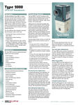
1
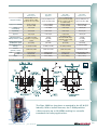
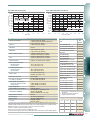
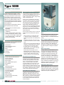
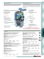
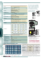
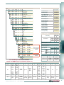
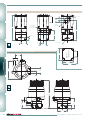
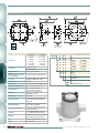
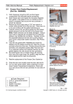
I/P, E/P & P/I
Transducers
Type 1000
Type 1000EX
Type 1000HR
Type 1000 Hazardous Use
Type 1001
Type 1001 Nema 3R
Type 1001 Nema 4X
Type 1500 Zero Based
Type 2000
Type 2000 Hazardous Use
Transducers
Type 1500
Type 5000
www.marshbellofram.com • 800.727.5646
57
Type 1000
I/P & E/P Transducers
Description
The Type 1000 Transducer is an electro-pneumatic device that reduces a supply pressure to a
regulated output pressure directly proportional
to an electrical input signal. The Type 1000
accepts a wide range of supply pressures,
ranging from a minimum of 3 psig (0.2 BAR)
above the maximum output up to 100 PSIG (6.9
BAR). An integral pneumatic volume booster
is included in the design to provide high flow
capacity (up to 12 SCFM/339 SLPM). Model
selections include general purpose, NEMA 4X
Type, extended range, high relief, intrinsically
safe, and explosion proof.
Applications
The Type 1000 Transducer converts an electrical signal to a pneumatic output which can be
used to operate the following:
Transducers
• Valve actuators
• Damper and louver actuators
• Valve positioners
• Controllers
• Relays
• Air cylinders
• Clutches and brakes
Used in:
• Liquid, gas and slurry processing instrumentation
• HVAC systems
• Paper handling controls
• Textile processing systems
• Energy management systems
• Petrochemical processing systems
Standard Features
• Low Cost
• Built-in Volume Booster
• Small Size
• Field Reversible
• Low Air Consumption
• Mounts at Any Angle
• Convenient External Span & Zero Adjusts
(Except for Explosion Proof Models)
• Light Weight
• Wide Supply Pressure Range
• Low Supply Pressure Sensitivity
Principle of Operation
The Type 1000 Transducer is a force balance
device in which a coil is suspended in the
field of a magnet by a flexure. Current flowing
through the coil generates axial movement of
the coil and flexure. The flexure moves against
the end of a nozzle, and creates a back pressure
in the nozzle by restricting air flow through it.
This back pressure acts as a pilot pressure to
an integral booster relay. Consequently, as the
input signal increases (or decreases, for reverse
acting), output pressure increases proportionally. Zero and span are calibrated by turning easily accessible adjusting screws on the front face
of the unit. The zero adjusting screw causes the
nozzle to move relative to the flexure. The span
adjusting screw is a potentiometer that limits
the current through the coil. A thermistor circuit
in series with the coil provides temperature
compensation.
Transducers
Split Ranging
The 4-20 mA input, 3-15 PSIG output model can
be recalibrated to provide 3-9 PSIG or 9-15 PSIG
output, for split ranging applications.
Mounting
The Type 1000 transducers can be pipe, panel,
or bracket mounted in any position. Positions
other than vertical will require recalibration
of the zero adjustment. For maximum output
pressure stability, the Type 1000 should be
mounted in a vibration-free location or such that
vibration is isolated to the X and Z axis shown
on the dimensional drawings.
Field Reversible
All Type 1000 transducers are calibrated at the
factory for direct acting operation but may be
used in the reverse acting mode by reversing
the polarity of the signal leads and recalibrating. When calibrated for reverse acting applications, the Type 1000 transducers provide a
minimum of their full rated output pressure (i.e.,
15, 27, or 30 PSIG) upon input signal failure.
Type 1000 for Extended Range
Description
The Bellofram Extended Range I/P and E/P
Transducers are based on Bellofram’s proven
Type 1000 transducer line - the best selling
transducers in the business.
The large span adjustment range of this line
allows recalibration to fit applications with
output ranges from approximately 3-35 PSIG
(0.2-2.4 BAR) to 3-145 PSIG (0.2-10 BAR).
58
Type 1000
The units accept supply pressures up to 150
PSIG (10.5 BAR) and provide flow capacity to
24 SCFM (677 SLPM).
The Type 1000 I/P and E/P Transducers are
more cost effective and more accurate than
typical high output systems using transducers
coupled to boosting or multiplying relays.
Type 1000 with High Relief
Description
Expanding upon the proven accuracy, reliability, and rugged construction of the Type 1000
General Purpose, these transducers provide
extra fast “blowdown” for a very rapid release
of downstream pressure. The extra relief feature
makes these units suitable for cylinder return
stroke actuation, air hoists, and similar applications requiring fast exhaust. These units accept
supply pressures to 100 PSIG (6.9 BAR), with
output ranges from 1-17 PSIG (0.07-1.2 BAR) to
6-30 PSIG (0.4-2.1 BAR), and provide exhaust
capacities of 7 SCFM (336 SLPM).
800.727.5646 • www.marshbellofram.com
Type 1000 Transducers
Type 1000
General Purpose
Type 1000
High Relief
Type 1000
Extended Range
Supply Pressure Range
3 PSIG (0.2 BAR) above max.
output to 100 psig (7 BAR)
50 PSIG max. for 1-17 psi models
3 PSIG (0.2 BAR) above max.
output to 100 PSIG (7 BAR)
Supply Pressure Sensitivity
±0.15% of span per
1.5 PSIG (0.1 BAR)
±0.15% of span per
1.5 PSIG (6.1 BAR)
5 PSIG (0.4 BAR) above max.
output to 150 PSIG (10.4 BAR)
(100 PSIG / 7 BAR for 2-60 PSIG /
0.1-4.1 BAR models)
±0.004% of span per
1.0 PSIG (0.07 BAR)
Linearity
(terminal based)
<1.0% of span
<1.0% of span
<2.0% of span
<1.0% of span
Repeatability
<0.5% of span
<0.5% of span
<0.5% of span
<0.5% of span
Hysteresis
<1.0% of span
<1.0% of span
<1.0% of span
<1.0% of span
Minimum Flow Rate at
Midrange 100 PSIG / 7 BAR
12 SCFM (339 SLPM)
(4.5 SCFM for 1-17 psi model)
12 SCFM
(339 SLPM)
Exhaust Capacity @ 5 psig
(0.4 BAR) above setpoint
2 SCFM
(56.5 SLPM)
7 SCFM
(336 SLPM)
24 SCFM (677 SLPM)
150 PSIG (10.4 BAR) Supply
(12 SCFM for 2-60 psi model)
2 SCFM
(56.5 SLPM)
Air Consumption (max) at
Midrange
0.1 SCFM (2.8 SLPM)
0.1 SCFM (2.8 SLPM)
0.07 SCFM (2.0 SLPM)
Port Size
(pneumatic / electric)
inches
Size
mm
1/4 NPT and 1/2 NPT
1/4 NPT and 1/2 NPT
1/4 NPT and 1/2 NPT
1/4 NPT and 1/2 NPT
2-1⁄8 X 2-1⁄8 X 4
54 X 54 X 101
2-1⁄8 X 2-1⁄8 X 4
54 X 54 X 101
2-1⁄8 X 2-1⁄8 X 4
54 X 54 X 101
6-13⁄32 X 5-15⁄16 X 7-9⁄16
163 X 151 X 192
Weight
2.1 lb. / 0.95 Kg
2.1 lb. / 0.95 kg
2.1 lb. / 0.95 kg
5.2 lb. / 2.4 kg
Type 1000
Explosion Proof
3 PSIG (0.2 BAR) above max.
output to 100 PSIG (7 BAR)
±0.15% of span per
1.5 PSIG (0.1 BAR)
12 SCFM
(339 SLPM)
2 SCFM
(56.5 SLPM)
0.1 SCFM (2.8 SLPM)
Transducers
Type 1000 Dimensional Drawing
The Type 1000 has long been a standard in the I/P & E/P
industry. With a built-in booster, the T-1000 provides
a flow capacity up to 12 SCFM, making it a versatile
transducer for many applications.
www.marshbellofram.com • 800.727.5646
59
Type 1000 General Purpose Ordering Information
Output*
Impedance
Input
Part Number
(Nominal)
BAR
PSIG
0.2-0.6
3-9
0.6-1.0
9-15
0.2-1.0
3-15
0.2-1.9
3-27
4-20mA
0.4-2.1
6-30
0.07-1.2
1-17
0.2-1.0
3-15
0.2-1.0
3-15
0.2-1.9
3-27
10-50mA
0.4-2.1
6-30
0.2-1.0
3-15
0.2-1.9
3-27
0-5V
0.4-2.1
6-30
0.2-1.0
3-15
0.2-1.9
3-27
1-9V
0.4-2.1
6-30
NOTE: For NEMA4X, add 004 suffix.
961-072-000
961-073-000
961-070-000
961-074-000
961-075-000
961-116-000
961-089-000
961-076-000
961-077-000
961-078-000
961-079-000
961-080-000
961-081-000
961-085-000
961-086-000
961-087-000
90 Ω
90 Ω
180 Ω
220 Ω
220 Ω
250 Ω
180 Ω
70 Ω
85 Ω
85 Ω
615 Ω
530 Ω
530 Ω
985 Ω
840 Ω
840 Ω
Type 1000 Extended Range Ordering Information
Input
0-60mA
4-20mA
Transducers
0-10V
0-5V
Output
*
Part Number
Impedance
(Nominal)
BAR
PSIG
0.1-8.3
0.2-8.3
0.1-4.1
0.2-8.3
2-120
3-120
2-60
3-120
961-107-000
961-111-000
961-117-000
961-112-000
220 Ω
260 Ω
225 Ω
805 Ω
0.1-4.1
2-60
961-118-000
500 Ω
Type 1000 High Relief Ordering Information
Output*
Impedance
Input
Part Number
(Nominal)
BAR
PSIG
4-20mA
10-50mA
0.2-0.6
0.6-1.0
0.2-1.0
0.2-1.9
0.4-2.1
0.2-1.0
0.07-1.2
0.2-1.0
0.2-1.9
0.4-2.1
3-9
9-15
3-15
3-27
6-30
3-15
1-17
3-15
3-27
6-30
961-130-000
961-131-000
961-132-000
961-133-000
961-134-000
961-135-000
961-136-000
961-137-000
961-138-000
961-139-000
90 Ω
90 Ω
180 Ω
220 Ω
220 Ω
180 Ω
250 Ω
70 Ω
85 Ω
85 Ω
Magnet
Assembly
Coi l
Atmospheric
Pressure
Pilot
Pressure
Exhaus t
Valve
Supply
Pressure
Atmosphere
Supply
Pressure
Regulated
Pressure
Agency Approval Notes
Factory Mutual
T-1000 I/P Transducers
Intrinsically Safe: Class I, Division 1, Groups A, B, C, & D, T6
Non-Incendive: Class I, Division 2 , Groups A, B, C, & D, T6.
T-1000 I/P / E/P Transducer
Explosion Proof: Class I, Division 1, Group D, T6
Dust-Ignition Proof: Classes II & III, Division 1, Groups E, F, & G, T6
Type 4 NEMA 4
Canadian Standards Association
T-1000 I/P Transducers
Hazardous Locations: Class I, Group D; Class II, Groups E, F, & G;
Class III; CSA Enc. 4 NEMA 4:
I/P transducer, supply pressure 100 psig max, input 4-20mA, output 3-15 psig.
Intrinsically Safe and Non-Incendive Systems - For Hazardous
Locations: Class I, Groups A, B, C, & D; Class II, Groups E, F, & G; Class III:
I/P transducer rated input 4-20mA, intrinsically safe when connected through CSA Certified
diode safety barriers in accordance with Bellofram Installation Instruction.
Explosion proof, intrinsically safe, and non-incendive ratings are not affected by recalibrating
for split range or reverse acting applications.
The Bellofram T-1000 Transducers were tested and found to comply with Electromagnetic
Compatibility Directive effective January 1, 1996. The relevant EMC specifications tested
were the following: EN 50081-1 (1992) and EN 50082-1 (1992). A Technical Construction
File, Serial #107 was written and Certificate of Conformity issued by a Competent Body.
Filter Note
Part Number
60
Outlet
Pr essure
Suppl y
Valve
Type 1000 Options and Accessories
Explosion Proof Mounting Kit
Explosion Proof Panel Mounting Kit
DIN Rail Kit
Hirschman Connector Kit (3-prong)
Filter Kit, 60 micron
Output Gauges
Dielectric Strength Testing
NEMA 4X Type Enclosure Option
Fle xure
Circui t
Board
Nozzle
971-079-000
971-078-000
010-115-000
971-126-000
010-139-000
Option “8” ie: last 3 digits become - 008
Option “12” ie: last 3 digits become - 012
Option “4” ie: last 3 digits become - 004
Bellofram specifies the use of instrument quality air
(clean, dry, oil-free) for all transducers. The use of
filters in the supply air system is highly recommended. Contact us for information on our filters
and filter regulators.
* For output pressures less than 3 PSI (0.2 BAR) or
greater than 30 PSI (21 BAR), the Type 1000 transducer
can be coupled to Bellofram Type 75 pneumatic relay.
Consult Applications Engineers for further information.
** NEMA 4 type enclosure option available on all input/
output ranges. This option is separate from explosion
proof, NEMA 4 units.
800.727.5646 • www.marshbellofram.com
Type 1000 Explosion Proof Dimensional Drawing;
Optional Mounting Bracket & Hardware
Optional Mounting Hardware
Order kit #201-971-079-000
Order Kit #201-971-078-000
Transducers
Drawings and dimensions
are for reference only.
Type 1000 Hazardous Location Use Ordering Information
Output*
Agency Approvals
Input
Part Number Impedance
(Nominal)
(See notes)
BAR
PSIG
Type 1000 Explosion Proof
0.2-1.0
3-15
961-098-000
4-20mA
0.2-1.0
3-15
961-098-100
20-100
3-15
961-142-000
1-9v
Type 1000 Intrinsically Safe
0.2-1.0
3-15
961-099-000
0.2-1.9
3-27
961-100-000
0.2-1.0
3-15
961-105-000
0.2-1.9
3-27
961-106-000
4-20mA
0.4-2.1
6-30
961-101-000
1.0-0.2
15-3
961-175-000
1.9-0.2
27-3
961-176-000
2.1-0.4
30-6
961-177-000
180 Ω
180 Ω
985 Ω
Explosion-Proof, Factory Mutual1
CSA Explosion Proof
Explosion Proof Factory Mutual1
180 Ω
220 Ω
180 Ω
220 Ω
220 Ω
180 Ω
220 Ω
220 Ω
Intrinsically Safe, Factory Mutual 3,4
Intrinsically Safe, Factory Mutual 3,4
Intrinsically Safe, CSA5
Intrinsically Safe, CSA5
Intrinsically Safe, Factory Mutual 3,4
Intrinsically Safe, Factory Mutual 3,4
Intrinsically Safe, Factory Mutual 3,4
Intrinsically Safe, Factory Mutual 3,4
*For output pressures less than 3 psi or greater than 30 psi the Type 1000 transducer can be coupled to
Bellofram Type 75 pneumatic relay. Consult application engineers for further information.
www.marshbellofram.com • 800.727.5646
61
Type 1001
I/P & E/P Transducers
Description
The Type 1001 is a patented family of electropneumatic instruments that is used to reduce a
supply pressure to a regulated output pressure
which is directly proportional to a two-wire
current or three-wire voltage input. This design
incorporates closed loop sensing of the output
pressure to achieve excellent accuracy and vibration stability. It also features a unique damping
circuit which can be adjusted to prevent overshoot and actuator “hunting.” Model selection
includes General Purpose (NEMA 1), Rainproof
(NEMA 3R), and Watertight/Corrosion Resistant
(NEMA 4X). NEMA 4X models are also explosionproof, and all models are intrinsically safe.
Transducers
Features
• 0.1% accuracy typical
• Closed loop pressure feedback control
minimizes effects of vibration, temperature,
supply pressure and mounting angle
• Built-in volume booster provides flows up to
12 SCFM
• Easy access zero and span adjustment
• Damping pot prevents over shoot and “hunting”
• Low air consumption
• Mounts at any angle (NEMA 3R limited)
• Compact and lightweight
• Virtually no sensitivity to supply pressure
changes
• Removable orifice (screw) for easy
maintenance
Applications
The Type 1001’s precisely regulated pneumatic
output can be used to operate:
• Valve actuators
• Louver and damper actuators
• Valve positioners
• Relays
• Clutches and brakes
• Controllers
• Air cylinders
Industry Applications Include:
• Liquid and Gas Processing
• Pulp and Paper
• Petrochemical Processing
• HVAC Systems
• Textile Productions
• Energy Management
• Environmental Control
• Medical Equipment
Calibration Adjustments
The Type 1001 contains multi-turn Zero and Span
adjustment potentiometers which are accessible
on NEMA 1 models by sliding the cover window
62
open to its first detent position. Pots are clearly
distinguished by legend on the cover. On NEMA
3R and 4X models, the cover should be removed to
reach the pots (marked Z for zero and S for span).
Adjust the pots clockwise to increase Zero and
Span as required to optimize factory set output
with appropriate input signal and supply pressure
applied.
Damping Adjustment
To eliminate undesirable system oscillation, the
Type 1001 features a unique damping adjustment. The output response is optimized to
varying downstream volumes by adjusting the
feedback time constant of the coil drive amplifier.
This is accomplished on NEMA 1 models by sliding the cover window open to its second detent
position to expose the single-turn Damping Potentiometer (remove the cover on NEMA 3R and 4X
models). To optimize response, turn the pot fully
counterclockwise until system oscillation is just
eliminated. System oscillation may be observed
by monitoring output pressure or by observing
the behavior of directly actuated system components in response to a changing input.
Type 1001
Transducers
Mounting
The Type 1001 transducers are designed to be
position insensitive. They can be panel, valve, or
pipe mounted at any angle (see NEMA 3R limitation) without a need for in place recalibration.
Panel mounting can be either direct or with the
bracket furnished with each unit. Mounting holes
are located on the bottom and side to provide
maximum mounting flexibility. Users may order
the optional DIN Rail Adapter or a bracket suitable for either valve or 2" pipe mounting. Special
pipe clamps may be ordered as a separate kit.
Agency Approval Notes
Factory Mutual
T-1001 I/P and E/P Transducers
Intrinsically Safe:
Class I, Division 1, Groups A, B, C, & D, T6 Ta = 40°C
Non-Incendive: Class I, Division 2, Groups A, B, C, & D, T6
Entity Parameters: VMax = 28 V, IMax = 150 mA, Ci = 0.22 µF, Li = 0.
T-1001 I/P and E/P Transducers Explosion Proof: Class I,
Division 1, Groups B, C, & D, T6
Dust-Ignition Proof: Classes II & III, Division 1, Groups
E, F, & G, T6 Type 4X NEMA 4X
Canadian Standards Association
T-1001 and T-1001XP I/P and E/P Transducers
Hazardous Locations: Class I, Groups B, C, & D; Class
II, Group E, F, & G; Class III; Encl 4 NEMA 4:
I/P or E/P transducer, input 4-20,10-50mA dc, 0-5, 1-5, 1-9 &
1-10V dc; supply voltage 40V dc max; supply current 100mA
max; maximum ambient temp 70˚C.
Output pressure ranges:
Standard: 3-9, 9-15, 3-15, 3-27, 6-30, 1-17 psig.
Extended: 0-15, 0-120 psig.
T-1001 I/P and E/P Transducers
Hazardous Locations:
Class I, Division 2, Groups A, B, C, & D:
I/P transducer, rated input 4-20mA or 10-50mA, 30V dc max.
E/P transducer, rated supply 24V dc, 10mA, rated 0-5, 1-5,1-9
& 1-10V dc. IN COMPLIANCE WITH STD C22.2 No 213.
Intrinsically Safe and Non-Incendive Systems - Hazardous Locations:
Class I, Groups A, B, C, & D:
I/P transducer, rated input 4-20mA or 10-50mA, 30V dc max;
intrinsically safe when connected through CSA Certified zener
barrier devices or converters as per Bellofram Installation
Instruction.
E/P transducer, rated supply 24V dc, 10mA; rated input 0-5,
1-5, 1-9 & 1-10V dc; intrinsically safe when connected through
CSA Certified zener barrier devices as per Bellofram Installation Instructions.
The Bellofram T-1001 Transducers were tested and found to
comply with Electromagnetic Compatibility Directive effective
January 1, 1996. The relevant EMC specifications tested were
the following: EN 50081-1 (1992) and EN 50082-1 (1992).
A Technical Construction File, Serial #107 was written and
Certificate of Conformity issued by a Competent Body.
800.727.5646 • www.marshbellofram.com
Type 1001: Exhaust Capacity
Type 1001: Output Pressure Droop
PSIG BAR
10 0.69
9 0.62
8 0.55
7 0.48
6 0.41
5 0.35
4 0.28
3 0.21
2 0.14
1 0.07
0 0
SCFM 0
LPM 0
OUTPUT PRESSURE
PRESSURE ABOVE SETPOINT
1
28
2
57
3
85
REVERSE FLOW
4
113
5
142
6
170
12
57
Type 1001 Specifications
Accuracy (per ISA 51.1)
Hysteresis
Dead Band
Repeatability
Ambient Temperature Effect
Span
Temperature Effect
Operating Temperature Range
Buna-N elastomers
Viton elastomers
Storage Temperature Range
Buna-N elastomers
Viton elastomers
Vibration Effect
Mounting Position Effect
Loop Load, I/P Transducer
Supply Voltage, E/P Transducer
Intrinsically Safe/Nonincendive
General Purpose
Supply Voltage Effect
Signal Impedance, E/P Transducer
RFI/EMI Effect (NEMA 4X)
Supply Pressure Sensitivity
Air Consumption:
Supply Pressure
Port Sizes
4
113
6
170
8
10
227
283
FORWARD FLOW, SCFM
12
340
14
397
16
453
Type 1001 Accessories
± 0.10% of output span, typical
± 0.25% of output span, maximum (Guaranteed)
0.01% of output span, typical
0.10% of output span, maximum
No effect
0.01% of output span, typical
0.10% of output span, maximum
± 0.004% of nominal span per °F, typical
±0.022% of nominal span per °F, maximum
±0.013% of calibrated span per °F, typical
±0.022% of calibrated span per °F, maximum
0.02%/°F, zero and span effects combined
-20°F to 160°F (-29 to 71°C)
0°F to 160°F (-18 to 71°C)
-40°F to 200°F (-40 to 93°C)
-15°F to 200°F (-26 to 93°C)
Less than 0.5% of span per 1G,
5-2000 Hz, 3G maximum, 3 axes
Not measurable
Less than 10 VDC drop at 20 mA
Less than 12 VDC drop at 50 mA
9 VDC to 28 VDC, less than 20 mA
9 VDC to 40 VDC, less than 20 mA
No effect
6000 Ohm minimum
Less than 0.25% of span change in output
10V/meter, 20-1000 MHz.
(Reference SAMA PML 33.1-1978, 2-abc)
No effect
0.07 SCFM (2 LPM) maximum
100 psig (6.9 BAR) maximum
Pneumatic: 1/4 NPT
Electrical: 1/2 NPT
* For models with zero output capability maximum supply pressure = 40 PSI (2.8 BAR) above maximum output, except for
0-100 PSI and 0-120 PSI models that have a maximum supply pressure of 130 PSI (9 BAR) & 140 psi (9.7 BAR) respectively.
Bellofram specifies the use of instrument quality air (clean, dry, oil free) for all transducers.
Transducers should be used within the following conditions:
Dew Point < 35°F (2°C) (indoor); Oil Content < 1PPM; Particles < 3µm.
The use of filters in the supply air system is highly recommended. Contact us for information on our filters and filter regulators.
www.marshbellofram.com • 800.727.5646
Part
Number
Kits
Std./Nitrile Repair Kit
Std./Fluorocarbon Repair Kit
Extended Range/Nitrile Repair Kit
Extended Range/Fluorocarbon
Repair Kit
Panel Mounting Kit
***
Valve Mounting Kit
2" Pipe Mounting Kit
(Valve Mounting Kit is required)
DIN Rail Adapter
Cover for Locking Device Kit
(for NEMA 4X enclosure only)
Type 1 Orifice with Buna-N O-rings*
971-122-001
971-122-002
971-122-003
971-122-004
010135-000
010134-000
010143-000
010115-000
010136-000
010137-000
010137-002
**
Type 2 Orifice with Buna-N O-rings 010137-001
Type 2 Orifice with Viton O-rings** 010137-003
Filter Kit, 60 microns
010139-000
Type 1 Orifice with Viton O-rings*
Hirschmann® Connector Kit
(Din 43 650-A)
(3 prong plug, O-ring sealed)
Pressure Gauge Kit, 15 PSI
Pressure Gauge Kit, 30 PSI
Pressure Gauge Kit, 60 PSI
Pressure Gauge Kit, 160 PSI
Transducers
PSIG BAR
10 0.69
9 0.62
8 0.55
7 0.48
6 0.41
5 0.35
4 0.28
3 0.21
2 0.14
1 0.07
0 0
SCFM 0
LPM 0
010142-000
010138-000
010138-001
010138-002
010138-003
* Type 1 Kits to be used with Ø based output units and
1-17 PSIG unit.
** Type 2 Kits to be used with all other units.
*** Supplied standard with Nema 4X
Type 1001 Specials Table
Input
Output
Comments Part Number
NEMA 1
962-145-000
4-20 mA 20-100 kPa NEMA 3R
962-146-000
4-20 mA 0-200 kPa
962-148-000
4-20 mA 20-100 kPa
NEMA 1
63
Type 1001 Ordering Information
9 6
0
Enclosures
NEMA 1, General Purpose2
NEMA 3R, Rainproof2
NEMA 4X, Water-tight, Dust-tight, Corrosion Resistant, and Explosion-Proof2
6
7
8
_ _
Calibration
See Input / Output matrix below1
Agency Approvals
Intrinsically Safe (standard)
Factory Mutual and CSA Explosion Proof
0
1
Options
00 None
06 Fluorocarbon Elastomeric Diaphragm
Notes to Nomenclature:
1. Transducer operating in the voltage mode (E/P), can be adjusted with the “span” potentiometer for any input between
0-10 VDC. The input range is limited to a minimum 4VDC difference between 100% and 0% Input voltage.
2. Standard NEMA 1 enclosure is conversion coated only. Standard NEMA 3R and NEMA 4X enclosures are epoxy painted.
Span Potentiometer
Zero Potentiometer
Damping Potentiometer
Terminal Block
Ground Screw
Transducers
1/2 NPT Electrical Port
Coil
Coil Wire Connector
Removable Orifice
1/8 NPT Gauge Port
1/4 NPT Supply Pressure Port
Type 1001 Standard Input/Output Matrix
64
PSIG
0-5
0-15
0-30
0-60
0-100
1-17
3-15
3-27
6-30
3-9
4-20 mA
10-50 mA
0-5 VDC
1-5 VDC
1-9 VDC
1-10 VDC
0-10 VDC
19
11
06
20
08
09
05
02
03
04
00
16
A5
98
89
15
12
87
14
10
9-15
0-2
0-120
01
13
07
90
B1
17
21
26
18
28
29
25
22
35
24
30
31
B2
27
A1
36
A6
38
39
97
32
33
34
50
41
B3
37
A2
46
40
48
49
45
42
43
44
60
51
B4
47
A3
56
B6
58
59
55
52
53
54
88
61
B5
57
A4
66
70
68
69
65
62
63
64
80
99
23
67
800.727.5646 • www.marshbellofram.com
Front View
Side View
Transducers
Side View (Vertical Mount Only) NEMA 3R
Atmosphere
Supply Pressure
Pilot Pressure
Regulated Pressure
Top View
Bottom View
www.marshbellofram.com • 800.727.5646
65
Side Views
Type 1001 EX Wiring Termination
PWB Terminal Block
I/P Transducer
E/P Transducer
Position 3
Position 2
Position 1
Positive (+)
No Connection
Negative (-)
Supply (+)
Common
Signal (+)
Transducers
Bottom View
66
800.727.5646 • www.marshbellofram.com
Type 1500
I/P & E/P Transducers
The T-1500 is a new series of electro-pneumatic
transducers that convert an electrical signal
to a proportional pressure output. It provides
precision electro-pneumatic control to actuators,
valves, positioners, final control elements and
is ideally used for high-flow control devices.
The Type 1500's compact size and accessibility
to ports and adjustments allow the unit to be
installed in space-constrained locations or in a
manifold for multi-device control.
DIN rail and manifold assemblies are available
in kits that provide three, five or ten mounting
points.
An integral pneumatic volume booster is included in the Type 1500 design to provide high
flow capacity. (See specifications for flow data.)
Standard Features
• Small footprint, compact size
• Manifold mounting configurations
• Built-in volume booster
• Electrical Connections: Conduit 1⁄2 NPT or
BSPT, Terminal Block, Hirschmann®
Connectors (DIN 43 650-A)
• Supply and output ports on
front and back of unit
• Low air consumption
• External zero and span adjustments
• Low cost
• Field accessible orifice
• Electrical conduit connection
meets CE requirements
Options Available
• Intrinsically Safe (FM, CSA, ATEX)
• NEMA 4X (FM, CSA) Excludes Terminal Block
Applications
The T-1500 transducer can be used as an
electro-pneumatic control device to operate:
• Valve actuators
• Valve positioners
• HVAC systems
• Material handling systems
• Paper handling controls
• Automation systems
• Liquid and gas processing systems
www.marshbellofram.com • 800.727.5646
Principle of Operation
(See Fig. 2 and 6) The T-1500 Transducer
is a force balance device in which a coil is
suspended in the field of a magnet by a flexure.
Current flowing through the coil generates axial
movement of the coil and flexure. The flexure
moves against the end of a nozzle and creates
a back pressure in the nozzle by restricting air
flow. This back pressure acts as a pilot pressure
to an integral booster relay. Consequently, as
the input signal increases (or decreases for
reverse acting), output pressure increases
proportionally.
Type 1500
In the zero based T-1500, the output of the
transducer section is routed to an integral negative bias booster relay. The bias relay allows the
complete unit to regulate output pressure down
to 0 psig/BAR. The bias relay also amplifies the
output of the transducer which allows the zero
based units to regulate higher output pressures
than the standard T-1500.
Transducers
Zero and Span are calibrated by turning easily
accessible adjusting screws on the front face
of the unit (see Figures 3, 4, 5, 7, 8 and 9).
The zero adjustment causes the nozzle to move
relative to the flexure. The span adjustment is
a potentiometer that limits the flow of current
through the coil. A thermistor circuit in series
with the coil provides temperature compensation.
Transducers
Type 1500 Description
Mounting
The T-1500 can be mounted at any angle
but should be calibrated after mounting. For
maximum output pressure stability, the T-1500
should be mounted vertically in a vibration free
location or such that the vibration is isolated
to the X and Z axis. The T-1500 can be in-line,
panel, pipe, DIN rail or manifold mounted.
Air Connections
Supply
1. Supply Air must be instrument quality air
regulated between 5 PSI above maximum
output pressure up to 120 PSIG / 8.3 BAR
(See table: Supply Pressure Range).
Connect supply to either of two ports marked
“IN” on the base of the transducer. Avoid getting pipe sealant inside the piping or transducer.
2. Instrument-quality air consists of:
a. A dew point less than 35˚F
b. No particles larger than three microns
c. Maximum oil content of 1 ppm
Connect output to either of two ports marked
“OUT” on the base of the transducer. The
second “OUT” port may be used for a pressure
gauge.
Output
3. All unused ports must be plugged.
67
Type 1500 Transducers
Standard Range
Hysteresis
Repeatability
<0.75% of span
<0.5% of span
<0.75% of span
<1.0% of span for fluorocarbon units
6.5 SCFM (Minimum) @ 15.0 PSIG / 1.0 BAR
output pressure, 120 PSIG / 8.3 BAR supply pressure
3 SCFH @ 15 PSI / 1.0 BAR output pressure
>1.0 SCFM @ 5 PSI / 0.4 BAR above set point
Linearity (Independent)
Zero Based
<1.0% of span
<0.5% of span
<1.0% of span
9.0 SCFM (Minimum) @ 15.0 PSIG / 1.0 Bar
output pressure, 150 PSIG / 10.3 BAR supply pressure
18 SCFH @ Maximum output pressure
Maximum Air Consumption
>1.0 SCFM @ 5 PSI / 0.4 BAR above set point
Exhaust Capacity
0-15 units: 25-150 PSIG / 1.7-10.3 BAR
0-30 units: 40-150 PSIG / 2.8-10.3 BAR
5 psi above maximum output up to 120 psig / 8.3 BAR maximum
Supply Pressure Range
0-60 units: 70-150 PSIG / 4.8-10.3 BAR
0-120 units: 125-150 PSIG / 8.6-10.3 BAR
1.3 lbs.
1.63 lbs.
Weight
1/4 NPT, BSPT, BSPP
1/4 NPT, BSPT, BSPP
Port Size
<1.7% of span change in output pressure over
<2.5% of span for a supply pressure change of 15 PSIG / 1.0 BAR
Supply Pressure Sensitivity
full supply pressure range (0-120 units)
-20°F to +150°F
-20°F to +150°F
Temperature Range
4-20 mA DC, 0-5 VDC, 1-5 VDC, 1-9 VDC, 0-10 VDC, 1-10 VDC
4-20 mA DC, 0-5 VDC, 1-5 VDC, 1-9 VDC, 0-10 VDC, 1-10 VDC
Input Signal
3-15, 3-27, 6-30 PSIG
0-15, 0-30, 0-60, 0-120 PSIG
Output Range
0.2-1.0, 0.2-1.9, 0.4-2.1 BAR
0-1.0, 0-2.1, 0-4.1, 0-8.3 BAR
Electrical Connections: Both the I/P & E/P versions are two-wire devices, plus a safety ground. The E/P requires a DC voltage input signal; example: 1 to 9 VDC.
The I/P models require an input current of 4 to 20 mA.
Flow @ Mid Range
Type 1500 Ordering Information
96
Enclosure Rating
0 NEMA 4X (Includes Approvals)
6
9
Indoor Use / General Purpose
“In and Out” Pneumatic Port Connections
Transducers
1/4 NPT
1/4 BSPT
1/4 BSPP
7
8
9
Input (Signal)
4-20 mA DC
0-5 VDC
1-9 VDC
1-10 VDC
0-10 VDC
1-5 VDC
1
2
3
4
5
6
Output (Pressure)
3-15 PSIG / 0.2-1.0 BAR
3-27 PSIG / 0.2-1.9 BAR
6-30 PSIG / 0.4-2.1 BAR
0-15 PSIG / 0-1.0 BAR
0-30 PSIG / 0-2.1 BAR
0-60 PSIG / 0-4.1 BAR
0-120 PSIG / 0-8.3 BAR
0
1
2
3
4
5
6
Electrical Connection
1/2 NPT (1/4 NPT Ports Only)
Terminal Block (Indoor Use / General Purpose Only)
Hirschmann® Connection (DIN 43 650-A)
1/2 BSPT Conduit (1/4 BSPT or BSPP Ports Only)
0
1
2
3
Elastomer
0
1
Nitrile
Fluorocarbon
Agency Approvals and Certifications
0 FM, CSA and ATEX Intrinsically Safe
1 None - General Purpose Only
NOTE: Individual regulators, FRs, filters, and lubricators come complete with bracket.
FRL assemblies come complete with all bracket/connectors.
68
800.727.5646 • www.marshbellofram.com
T-1500 Manifold and Adapter Kit
Principle of Operation
The T-1500 manifold assembly allows multiple
T-1500 Transducers to be mounted in parallel.
This minimizes the number of individual supply
air lines required. Manifolds are available to
hold three, five, or ten units. Each manifold
comes with check valves so that a unit can be
pulled off of the manifold for service or replacement without affecting the whole manifold.
(See Figure 1.)
Type 1500 Dimensions
Number of
Transducers
Length A
Length B
3
7.57"
192.3 mm
173.5 mm
5
10.75"
273.1 mm
254.3 mm
10
6.83"
10.01"
18.70"
17.96"
475.0 mm
456.2 mm
Mounting
Figure 1 - Manifold Front View
T1500
TRANSDUCER
Z
S
2.50"
63.5mm
Air Supply Attachment
The air supply can be attached to either side
of the manifold via a 3/4 NPT connection or
to the back of the manifold via a 3/8 NPT connection. After an air supply port is selected, the
open ports should be plugged using the plugs
provided with the manifold kit and a pneumatic
sealant.
Output Air Attachment
Connect the output ports from each of the
T-1500 Transducers to the bottom or back of
the manifold. After connecting the transducers,
plug the other 1/8 NPT ports using the plugs
provided and a pneumatic sealant.
T-1500 Manifold Adapter Kit
The T-1500 manifold kit includes the adapter
kits required for each transducer.
Electrical Connections
Two brackets supplied with the manifold kit
allow an electrical conduit to be attached to
the manifold. Mounting screws and nuts are
provided, and the brackets have an 11/64"
diameter hole which will fit standard 8-36 UNF
or 8-32 UNC screws (not supplied).
www.marshbellofram.com • 800.727.5646
OUT
CHECK VALVES
IN
“B”
“A”
3.50"
88.9mm
CAPTIVE SCREW
Type 1500 Manifold Ordering Information
Kit
T-1500 Wall Mount Kit, 3 unit
T-1500 Wall Mount Kit, 5 unit
T-1500 Wall Mount Kit, 10 unit
T-1500 Manifold Adapter Kit (Replacement)
DIN Rail Mounting Kit
Pneumatic Repair Kit
(3-15, 3-27 PSIG / 0.2-1.0, 0.2-1.9 BAR)
Pneumatic Repair Kit
(6-30 PSIG / 0.4-2.1 BAR)
Pneumatic Repair Kit, Fluorocarbon
(3-15, 3-27 PSIG / 0.2-1.0, 0.2-1.9 BAR)
Pneumatic Repair Kit, Fluorocarbon
(6-30 psig / 0.4-2.1 BAR)
Pneumatic Repair Kit
(0-120 PSIG / 0-8.3 BAR)
Pneumatic Repair Kit Fluorocarbon,
(0-120 psi / 0-8.3 BAR)
Electronic Repair Kit (4-20 mA)
Electronic Repair Kit (0-5 VDC or 1-5 VDC)
Electronic Repair Kit (1-9, 1-10 VDC, or 0-10 VDC)
2" Pipe Mounting Kit
Filter Kit, 60 Micron
ADAPTER PLATE
Part Number
010-606-000
010-606-001
010-606-002
010-602-000
971-140-000
Transducers
The manifolds may be mounted flush with a
wall or cabinet or may be mounted away from
the wall. Both mounting options are included in
the basic manifold kit. In addition, all fittings
required to mount the full number of units in
each manifold are included in the basic kit. An
additional adapter kit may be purchased which
contains all of the hardware required to manifold mount a single T-1500 Transducer should
the need arise.
971-141-000
971-141-002
971-141-003
971-141-004
971-145-000
971-145-001
971-142-000
971-142-001
971-142-002
971-159-000
010-139-000
69
Type 1500 Extended Range Parts
Number
1
2
3
4
5
6
7
8
9
10
11
12
13
14
15
Figure 2: Type 1500 Extended Range Parts
Description
Circuit Board
Worm Gear
Duckbill Valve (NEMA 4X Only)
Magnet Assembly
Nozzle Assembly
Bonnet Gasket (NEMA 4X Only)
Servo Diaphragm (I/P Section)
Control Diaphragm (I/P Section)
Pintle
Supply Seat
Coil/Flexure Assembly
Servo Diaphragm (Bias Relay)
Control Diaphragm (Bias Relay)
Orifice Screw
Bias Spring
Type 1500 Extended Range Dimensions
Figure 3: Terminal Block
2.87"
62.9mm
1.52"
38.6mm
1.00"
25.4mm
Z
Transducers
ZERO
ADJUSTMENT
ORIFICE
SCREW
5.27"
133.9mm
Figure 4 - Hirschmann® (DIN 43 650-A)
Back Dimensions
10-32 UNF-2B
MOUNTING
HOLES
IN
TERMINAL "1"
Z
OUT
OUT
TERMINAL "2"
SPAN
ADJUSTMENT
S
OUT
2.77"
70.4mm
ZERO
ADJUSTMENT
ORIFICE
SCREW
5.27"
133.9mm
IN
S
OUT
IN
OUT
IN
SAFETY
GROUND
SPAN
ADJUSTMENT
3.51"
89.2mm
IN
2.01"
51.1mm
2.25"
57.2mm
0.52"
13.22mm
OUT
0.77"
19.6mm
IN
2.25"
57.2mm
FIGURE 5: 1/2 NPT / BSPT
3.16"
80.3mm
Z
ZERO
ADJUSTMENT
ORIFICE
SCREW
5.27"
133.9mm
2.25"
57.2mm
70
S
OUT
IN
OUT
IN
SPAN
ADJUSTMENT
Drawings and dimensions are for reference only.
800.727.5646 • www.marshbellofram.com
Figure 6: Type 1500 Standard Range Parts
Type 1500 Standard Range Parts
Number Description
Circuit Board
1
Worm Gear
2
Duckbill Valve (NEMA 4X Only)
3
Magnet Assembly
4
Nozzle Assembly
5
Bonnet Gasket (NEMA 4X Only)
6
Servo Diaphragm (I/P Section)
7
Control Diaphragm (I/P Section)
8
Pintle
9
Supply Seat
10
Coil/Flexure Assembly
11
Drawings and dimensions are for reference only.
Type 1500 Standard Range Dimensions
Back Dimensions
Figure 7: Terminal Block
1.52"
38.6mm
1.00"
25.4mm
2.87"
72.9mm
Y
10-32 UNF-2B
MOUNTING HOLES
X
Z
2.01"
51.1mm
OUT
Z
3.77"
95.8mm
ZERO
ADJUSTMENT
ORIFICE
SCREW
Vibration Axes
IN
SPAN
ADJUSTMENT
S
OUT
IN
0.52"
13.2mm
0.77"
19.6mm
Figure 9: Hirschmann® (DIN 43 650-A)
FIGURE 8: 1/2 NPT / BSPT
2.77"
70.4mm
3.16"
80.3mm
Z
3.77"
95.8mm
ZERO
ADJUSTMENT
ORIFICE
SCREW
OUT
S
Z
SPAN
ADJUSTMENT
3.77"
95.8mm
ZERO
ADJUSTMENT
ORIFICE
SCREW
IN
OUT
S
SPAN
ADJUSTMENT
IN
2.25"
57.2mm
2.25"
57.2mm
Agency Approvals
Transducers
2.25"
57.2mm
- Applies only to units ordered with approvals
Factory Mutual
T-1500 I/P and E/P Transducers
Intrinsically Safe: Class I, Division 1, Groups A, B, C, & D, T4 Ta = 70°C; Entity;
Non-Incendive: Class I, Division 2, Groups A, B, C, & D, T4 Ta = 70°C
Dust-Ignition Proof: Classes II & III, Division 1, Groups E, F, & G, T4 Ta = 70°C
Suitable: Classes II & III, Division 2, Groups F & G, T4 Ta = 70°C Type 4X NEMA 4X
Entity Parameters: VMax = 30 V dc, IMax = 100 mA, Ci = 0 µF, Li = 0 mH.
Canadian Standards Association
T-1500 I/P Transducers Hazardous Locations: Class I, Division 2,
Groups A, B, C, & D; Type 4X NEMA 4X:
I/P transducer, rated VMax = 30V dc, IMax = 100mA. Temp Code T4. Max ambient 70°C.
IN COMPLIANCE WITH STD C22.2 No 213.
Intrinsically Safe, Entity - Hazardous Locations: Class I, Groups A, B, C, & D;
Class II, Group E, F, & G; Class III; Type 4X NEMA 4X:
I/P transducer. Entity Parameters: VMax = 30V dc, IMax = 100mA, Ci = 0, Li = 0. Intrinsically Safe
when connected per Installation Instruction 010632. Temp Code T4. Max ambient 70°C.
www.marshbellofram.com • 800.727.5646
ATEX
Intrinsically safe for II 1 G EEx ia IIB T4 Tamb = -20 to 65˚C
Input Parameters: VMax = 30V, Pi = 1W, Ii = 100 mA, Req = 180 OHMS,
Ci = 0, Li = 24mH
Models are CE marked for use in the European Union, and meet the EMC
heavy machinery directives.
The Bellofram T-1500 Transducers were tested and found to comply with
Electromagnetic Compatibility Directive effective January 1, 1996.
The relevant EMC specifications tested were the following: EN 50081-1
(1992) and EN 50082-1 (1992). A Technical Construction File, Serial #107
was written and Certificate of Conformity issued by a Competent Body
71
Type 2000
I/P & E/P Transducers
Description
The Marsh Bellofram Type 2000 is a robust
electronic instrument that regulates an incoming supply pressure down to a precise output
pressure which is directly proportional to an
electrical control signal. The secret to the Type
2000’s precise, reliable performance under a
variety of demanding environmental conditions
is a patented piezo-ceramic actuator with many
industry-wide firsts.
The Type 2000 has been designed to meet the
electro-pneumatic needs of the world:
• Field-selectable inputs and direct/reverse/
split ranging
• Multiple input/output/mounting
configurations
• Precise, reliable performance under extreme
conditions of temperature, vibration, orientation, supply pressure changes, supply voltage
changes, RFI/EMI, humid / oil-laden media,
and corrosive surroundings
Applications
The Type 2000’s precisely regulated pneumatic
output can be used to operate:
Transducers
• Valve Actuators
• Louver and Damper Actuators
• Valve Positioners
• Relays
• Clutches and Brakes
• Controllers
• Air Cylinders
Industry Applications Include
• Chemical and Petrochemical Industries
• Petroleum Production
• Pipeline Transmission
• Electric Utilities
• Water and Wastewater Systems
• Pulp and Paper
• Textiles
• Semiconductor Industry
• Food and Beverage
• Environmental Control Systems
• Construction Equipment
• Agricultural Equipment
• Machine Tool
• Material Handling
• Automotive Testing and Assembly
• Medical Equipment
72
Principle of Operation
The Type 2000 I/P and E/P transducers utilize
closed-loop pressure feedback-control for precision
pressure output and minimized effects of temperature, supply pressure changes, supply voltage
changes, and mounting angle.
Supply pressure is reduced by the supply valve
to provide an output pressure which is internally
routed to a precision temperature compensated
piezo-resistive pressure sensor. Supply pressure
is also routed to an externally removable orifice
which provides a reduced pilot pressure to a
chamber containing a servo diaphragm and nozzle.
Pilot pressure is controlled by modulating the gap
between the face of a nozzle and an adjacent
piezo-ceramic actuator, which is part of a unique
patented mechanism.
The piezo-ceramic actuator serves as a control link
between electrical input and pressure output as
follows:
• The input current (I/P) or voltage (E/P) signal
is conditioned to provide a normalized control
signal directly proportional to the desired pressure
output.
• Simultaneously the output of the pressure sensor
is amplified and conditioned to produce a feedback
signal.
• The sum of the control signal and the feedback signal produce a command signal which is delivered
as a DC voltage to the piezo-ceramic actuator.
• As voltage increases, the force applied by the
actuator increases, so as to restrict nozzle bleed
and thus increase pilot pressure.
• Increased pilot pressure applied to the servo
diaphragm directly causes opening of the supply
valve and an increase in the output pressure until
the output feedback signal and control signal
combine to produce the correct command signal.
Fine-Tuning Your Application
For optimal performance in your application, the
calibration of the Type 2000 can be fine-tuned
in the field. An easily-removable cover provides
access to the isolated electronics. All potentiometers, connections, jumpers, and switches
are clearly marked on the circuit board or on the
handy chart located on the inside of the cover.
The three elements of calibration (Gain, Zero, and
Span) are described below. Consult the Type 2000
User’s Manual for detailed calibration procedures,
cautions, and instrumentation requirements.
Gain (Damping) Adjustment
The output response of the Type 2000 can be
optimized for varying downstream volumes by
adjusting the system gain of the control circuit.
Adjust the Gain Pot counterclockwise for increased
gain; clockwise for increased oscillation damping.
For maximum allowable gain in your application,
the pot should be turned clockwise until oscillation just disappears.
Type 2000
Transducers
Note
The combined adjustments of Gain, Zero and
Span are all interactive. It may take several
adjustment attempts to accomplish final desired
setting.
Zero and Span Adjustments
The Type 2000 contains multi-turn Coarse-Zero,
Fine-Zero, and Span adjustment potentiometers
which are clockwise positive. Adjustment of
either Zero Pot changes the unit’s minimum output while the Span Pot changes the maximum
output.
Wide Rangeability
The Type 2000 can be field calibrated to pressure ranges other than the standard ones by
combinations of recalibration, pressure range
switching, and split high/low ranging. A unit
should not be switched to a range outside its
pressure sensor family (eg., a 0-15 PSIG can be
switched to a 3-15 PSIG, but not to 0-30 PSIG).
(Caution: Do not exceed the range of the onboard pressure sensor.) For example, the easiest
way to recalibrate a 0-30 PSIG unit to 3-15 psig
would be to change the switch setting to 3-27
PSIG, then switch to split range low.
Field-Selectable Features
Onboard switches allow the user to easily reconfigure the Type 2000 for any of several electrical
inputs, direct/reverse acting, or output split-ranging high/low. Fine tuning of the unit’s calibration
may be necessary after a reconfiguration.
800.727.5646 • www.marshbellofram.com
Direct/Reverse Acting
Split Ranging (High or Low)
Direct Acting transducers regulate to their minimum output when supplied
with minimum input; maximum out with maximum in. Reverse Acting
transducers regulate to their maximum output at minimum input.
The Type 2000 can be configured to regulate either half (top or bottom)
of its normal output range, when supplied with its normal full-ranging
electrical input. For example, a 0-10V 0-30 PSI unit set to split range low
will regulate 0-15 PSI @ 0-10V. It will regulate 15-30 PSI @ 0-10V if set to
split range high.
Electrical Port Options
1) 1/2 NPT Conduit
2) 20mm Conduit
3) Hirschmann® (DIN 43 650-A)
4) Terminal Block
Easy Access Top Cover
1) Isolated electronics
2) Calibration adjustments
3) Configuration switches
4) Switch information on
inside of cover
Easy Access Orifice
Mounting Options
1) In-Line
2) Direct: Holes on left
rear and bottom faces
3) Bracket Mounting options:
Panel, Pipe, Valve, DIN-Rail
Output Port
Same as Input Port
(Not shown; rear face)
Input Port Options
1) 1/4 NPT
2) 1/4 BSPP
3) 1/4 BSPT
Integral Booster
Flows up to 21 scfm for quick
system response
Manifold-Mounting Option
Supply and Output ports on the
bottom face rather than “through
the body”
Gauge Port
1/8 NPT on all models
(Not shown; rear face)
- Applies only to units ordered with approvals
Transducers
Agency Approvals
It is mandatory for the user to install a
suitably rated NRTL Listed or Certified conduit seal
Factory Mutual
E Model with F approval, Explosion Proof/Intrinsically Safe
Not for use with natural gas or other Non-inert Gases
Explosion Proof: Class I, Div 1, Groups A, B, C&D; T6, Ta = 60˚C
Dust-Ignition Proof: Classes II & III, Div 1, Groups E, F&G; T6, Ta = 60˚C
TYPE 4X, IP 66
Intrinsically Safe: Class I, II & III, Div 1, Groups A, B, C, D, E, F & G; T4, Ta = 60˚C;
TYPE 4X, IP 66
Non-Incendive: Class I, Div 2, Groups A, B, C & D; T4, Ta=60˚C
Suitable: Class II, Div 2, Groups F & G; T4, Ta = 60˚C
Suitable: Class III, Div 2; T4, Ta = 60˚C
Type 4X, IP 66
Entity Parameters:
I/P:
VMAX=30V,
IMAX=200 mA,
E/P: VMAX=30V,
IMAX=100 mA,
PMAX=1W,
PMAX=0.75 W,
Ci= 0, Li=0
Ci= 0, Li=0
E Model with G approval, Explosion Proof,
United States and Canada
For use with natural gas or other non-inert gases as a process
medium up to a maximum input pressure of 140 PSI when
installed with suitable NRTL listed, certified or approved conduit
seal installed at the enclosure.
Explosion Proof: Class I, Div 1, Groups A, B, C & D, T6 Ta = 60˚C
Dust-Ignition Proof: Classes II&III, Div 1, Groups E, F & G, T6 Ta = 60˚C
NEMA 4X, IP 66
S Model, Intrinsically Safe
Intrinsically Safe: Class I, II & III, Div 1,
Groups A, B, C, D, E, F & G, T4 Ta = 60˚C;
Non-Incendive: Class I, Div 2, Groups A, B, C & D, T4 Ta=60˚C
Suitable: Class II, Div 2, Groups F & G, T4 Ta=60˚C
Suitable: Class III, Div 2, T4 Ta=60˚C
Type 4X, IP 66
Entity Parameters:
I/P:
VMAX=30V,
IMAX=200 mA,
E/P:
VMAX=30V,
IMAX=100 mA,
PMAX=1W,
PMAX=0.75 W,
www.marshbellofram.com • 800.727.5646
Ci= 0, Li=0
Ci= 0, Li=0
S Model with Terminal Block, Intrinsically Safe
Intrinsically Safe: Class I, Div 1, Groups A, B, C, D; T4, Ta = 60˚C;
Non-Incendive: Class I, Div 2, Groups A, B, C & D; T4, Ta=60˚C
Entity Parameters:
I/P:
VMAX=30V,
IMAX=200 mA,
PMAX=1W,
Ci= 0, Li=0
E/P: VMAX=30V,
IMAX=100 mA,
PMAX=0.75 W,
Ci= 0, Li=0
CANADIAN STANDARD ASSOCIATION
E Model with F approval, Explosion Proof/Intrinsically
Safe, Certified to Two Standards.
Certified to CLASS 2258 04 PROCESS CONTROL EQUIPMENT
Class I, Div 1&2, Groups A, B, C, D; Class II, Div1, Groups E, F and G; Div 2,
Groups F and G; Class III.
Rated: 28Vdc, 8mA, T6; Enclosure TYPE 4X, IP66; Max Ambient Temperature 60˚C.
Entity Parameters:
I/P:
V =30V
IMAX=200mA
Li=0µH MAX
E/P: VMAX=30V
IMAX=100mA
PMAX=1.0W
Ci=0µF
PMAX=0.75W
Ci=0µF
Li=0µH
Certified to CLASS 2258 02 PROCESS CONTROL EQUIPMENT
Class I, Div 1 & 2, Groups A,B,C,D; Class II, Div 1, Groups E, F, G; Div 2, Groups F & G; Class III
Rated: 28Vdc, 8mA, T6; Enclosure TYPE 4X, IP66; Max Ambient Temperature 60˚C.
Entity Parameters:
I/P: VMAX=30V
IMAX=200mA
E/P: VMAX=30V
IMAX=100mA
PMAX=1.0W
PMAX=0.75W
Ci=0µF
Ci=0µF
Li=0µH
Li=0µH
ATEX (European Model)
INTRINSIC SAFETY: II 1 G EEx ia IIC T4 (-20<Ta<+60) EN 50014: 1997 (A2) EN
50020:1994 EN 500284: 1999
The Bellofram T-2000 Transducers were tested and found to comply with Electromagnetic
Compatibility Directive effective January 1, 1996. The relevant EMC specifications tested
were the following: EN 50081-1 (1992) and EN 50082-1 (1992). A Technical Construction File,
Serial #107 was written and Certificate of Conformity issued by a Competent Body.
73
Type 2000 Specifications
0.1% of full-scale output typical (0.25% guaranteed); includes effects of
hysteresis, dead band, and repeatability
Accuracy
Electrical
Inputs
Connections
Power Supply
Direct/Reverse Acting
Switch-Selectable
4-20mA. 0-5, 1-5, 1-9, 1-10, or 0-10VDC
1/2 NPT or 20mm Conduit
DIN Hirschmann (S model only)
External Terminal Block (S model only)
5-28VDC (with voltage inputs only)
Switch-Selectable
The secret to the Type 2000’s
precise, reliable performance
under a variety of demanding
environmental conditions
is a patented piezo-ceramic
actuator with many
industry-wide firsts.
Pneumatic
Exhaust Capacity
0-5, 0-15, 3-15, 1-17, 0-30, 6-30, 3-27, 0-60, 0-100, or 120 PSIG
0-0.1, 0-0.3, 0-1.0, 0.2-1.0, 0.07-1.2, 0-2.1, 0.4-2.1, 0.2-1.9,
0-4.1, 0-6.9, 0-8.3 BAR
1/4" (NPT, BSPT, or BSPP threads)
Bottom-ported for Manifold Mounting
(Explosion proof only) 1/8 - 27 NPT
1/8 NPT
For 0–5 PSIG (0.3 BAR) Through 0–60 PSIG
From 5 PSIG (0.3 BAR) above maximum output to 100 PSIG maximum
For 0-100 PSIG and 0–120 PSIG Ranges
From 5 PSIG (0.3 BAR) above maximum output to 140 PSIG maximum
Switch-Selectable, Full-Range or Split-Range High or Split-Range Low
4 SCFH maximum (1.9 LPM)
Range
Sensor
Flow
PSIG
BAR
PSIG
BAR
SCFM
LPM
0-5
0-0.3
5
0.3
11
312
0-15
0-1.0
15
1.0
15
423
3-15
0.2-1.0
15
1.0
15
423
1-17
0.07-1.2
15
1.0
15
423
0-30
0-2.1
30
2.1
15
423
3-27
0.2-1.9
30
2.1
15
423
6-30
0.4-2.1
30
2.1
15
423
0-60
0-4.1
50
3.5
17
480
(Typical Flow @ 100 PSIG (6.9 BAR) in and maximum out)
0-100
0-6.9
100
6.9
21
595
0-120
0-8.3
100
6.9
21
595
(Typical Flow @ 140 PSIG (9.7 BAR) in and maximum out)
3 SCFM (85 LPM) @ 5 PSIG (0.3 BAR) above setpoint
(0-15 PSIG range unit set at mid range)
Stability
Supply Voltage Effect
Supply Pressure Effect
Vibration Effect
Mounting Position Effect
RFI/EMI
Temperature Effect
Storage Temperature
Approximate Weight
None
None
<1% FS (+/-1G; 5-1000Hz)
None
CE-Compliant
0.02% FS/˚F (-40˚ to 180˚F [-40˚ to 82˚C])
-40˚to 200˚F (-40 to 93˚C)
3.0 lbs, 1.35 kg
Outputs
Ports (Input/Output)
Exhaust
Ports (Gauge)
Supply
Split-Ranging
Consumption
Flow Capacity
Transducers
TYPE 2000: REGULATED PRESSURE VS. FLOW
PSIG BAR
70 4.8
140 psig supply pressure
REGULATED PRESSURE
60 4.1
50 3.4
40 2.8
30 2.1
20 1.4
10 0.7
0 0
SCFM 0
LPM 0
74
2
57
4
6
8
113 170 227
10 12 14 16
18 20 22 24
283 340 397 453 510 566 623 680
High Flow
Med Flow
Low Flow
FORWARD FLOW
Air Quality
Instrument-quality air consists of:
a. A dew point less than 35º F
b. No particles larger than three microns
c. Maximum oil content of 1 ppm
It is mandatory for the user to
install a suitably rated NRTL
Listed or Certified conduit seal
Type 2000 Mounting Options
Mounting Method
In-Line
Direct Mounting
Panel Bracket
Valve Bracket
Pipe Bracket
DIN-Rail Bracket
Manifold Plate
Intrinsically-Safe (S) Model
Yes
Side or Bottom Holes
Supplied
Accessory
Accessory
Accessory
Accessory
Explosion-Proof (E) Model
Yes
Side or Bottom Holes
Accessory
Supplied
Accessory
Accessory
Accessory
Mounting: The Type 2000 can be mounted in-line, or directly to a panel via mounting
holes located in the side and bottom of the unit. In addition, the S model includes a panelmounting bracket; while the E model includes a valve-mounting bracket. Kits are available
for mounting of either model to panel, valve, pipe, or DIN-Rail. A custom plate is available
for mounting of the bottom-ported version to a manifold. (See Accessories)
800.727.5646 • www.marshbellofram.com
Type 2000 Ordering Information
Type 2000 Accessories
2 K
Part Number
Enclosure
Panel Mounting Kit
010-135-000
Valve Mounting Kit
010-134-000
2" Pipe Mounting Kit
(Valve Mounting Kit is required)
010-143-000
DIN Rail Adapter
010-115-000
Pneumatic Ports
Manifold Adapter Kit
NPT
BSPT
BSPP
Manifold Mount3
Filter Kit, 60 microns
971-158-000
010-139-000
Pressure Gauge Kit
15 PSIG (1 BAR)
010-138-000
Pressure Gauge Kit
30 PSIG (2.1 BAR)
010-138-001
Pressure Gauge Kit
60 PSIG (4.1 BAR)
010-138-002
Pressure Gauge Kit
160 PSIG (11 BAR)
010-138-003
Intrinsically Safe
Explosion Proof
Electrical Port1
1/2 NPT Conduit
20mm Conduit ”S” Unit Only
Hirschmann5
Terminal Block2 ”S” Unit Only
N
M
H
T
N
T
P
M
6
Agency Approval
FM/CSA
ATEX ”S” Unit Only
FM Natural Gas Approved
for US and Canada4
F
C
G
Electrical Input
4-20 mA
0-5 V
1-5 V
1-9 V
1-10 V
0-10 V
42
05
15
19
11
01
Type 2000 Notes
1
Enclosure
S
E
Availability
Mode
Direct Acting
Reverse Acting
D
R
N
M
H
T
Electrical Port
Mode
Full Range
Split Range High
Split Range Low
F
H
L
005
015
315
117
030
630
327
060
0-5 PSIG
0-15 PSIG
3-15 PSIG
1-17 PSIG
0-30 PSIG
6-30 PSIG
3-27 PSIG
0-60 PSIG
0-0.3 BAR
0-1.0 BAR
0.2-1.0 BAR
0.07-1.2 BAR
0-2.1 BAR
0.4-2.1 BAR
0.2-1.9 BAR
0-4.1 BAR
100
120
0-100 PSIG
0-6.9 BAR
0-120 PSIG
0-8.3 BAR
Maximum Supply for
these regulators is
100 PSIG
Maximum Supply for
these regulators is
140 PSIG
00 None
It is mandatory for the user to install a
suitably rated NRTL Listed or Certified conduit seal
Type 2000 Wiring Connections and Switch Positions
Switch #
1: PSIG
BAR
2
3
4
ON
Switch #
1: PSIG
OFF
0-60
0-120
NEMA 4X / IP66 not available
Bottom O-Ring Ports
4
NRTL listed or certified conduit seal installed by user
5
Not Agency Approved
F
C
G
6
Agency Approval
FM/CSA ATEX Gas
S Intrinsic
Yes
Yes
No
Safety
Enclosure
E Explosion
Yes
No
Yes
Proof
3
Special
0-0.3
0-1.0
0.2-1.0
0.07-1.2
0-2.1
0.2-1.9
0.4-2.1
0-6.9
Yes
Yes
No
No
2
Pneumatic Output
0-5
0-15
3-15
1-17
0-30
3-27
6-30
0-100
Yes
Yes
Yes
Yes
Terminal Block I/P Transducer E/P Transducer
S
N/C
+ Signal
+
+ Signal
+ Power Supply
-
- Signal
Common
5
6: psig
BAR
7
8
9
0-0.3
0-1.0
0.07-1.2
0-2.1
0-4.1
0-6.9
0-8.3
Reverse
Acting
Full
I/P
1-5 VDC
0-5 VDC
Split Low
Voltage
Input
(E/P)
Split Low
Full
0-5
0-15
1-17
0-30
0-60
0-100
0-120
BAR
2
3
4
5
6: psig
BAR
7
8
9
0-4.1
0-8.3
1-9 VDC
0-10 VDC
4-20 mA
Split High
3-15
3-27
6-30
0.2-1.0
0.2-1.9
0.4-2.1
Direct
Acting
Split Low
Split High
E/P
www.marshbellofram.com • 800.727.5646
Full
Split High
Current
Input (I/P)
Transducers
S
E
75
Type 2000 Dimensions
1/2-14 NPT
.716
2X M3X0.5
X .250 DEEP
2X 8-32 UNC-2B
X .375 DEEP
MOUNTING HOLES
4.780
.360
3.883
OUT
1.893
IN
.570 TYP
.550
1.060
1/4-18 NPT TYP
Marsh
Bellofram
1.100
Type 2000 Explosion Proof Dimensions
2.307
1.37
[34.7]
2.225
Transducers
2.939
3.92
1.10
[99.5]
[27.9]
0.55
[14.0]
6.01
[152.6]
2.06
1.78
OUT
[52.3]
[45.2]
0.68
[17.3]
Drawings and dimensions are for reference only.
2.12
0.57
[14.5]
[53.8]
76
800.727.5646 • www.marshbellofram.com
Type 5000
P/I Transducers
Description
Features
The Type 5000 series is a compact, rugged and
reliable family of two-wire pressure transmitters designed for industrial field service. These
instruments convert a signal pressure input
into a precise 4-20 or 10-50mA output. The
lightweight transmitter housing includes a
1/4 NPT pressure port and a 1/2 NPT conduit
port for field wiring. Connections are easily
accessible simply by removing the top cover.
Zero and span adjustments are available within
the field wiring compartment for fine, on-site
calibration adjustment.
• 0.1% accuracy typical
• Piezo resistive pressure sensor resists vibration
• Mounts at any angle
• Easily accessible zero and span adjustments
• NEMA 4X housing approved for explosion
proof service
Type 5000
The Type 5000 uses a unique, temperature
compensated piezo resistive sensor suitable for
gauge pressure measurement of non-corrosive
liquids and gases. The sensor has excellent
dynamic response and is virtually insensitive
to mounting orientation and ordinary industrial
vibration. Mounting holes on the transmitter
housing are arranged to permit direct pipe (2")
mounting for minimum installed cost.
P/I Transducers
Transducers
Type 5000 Functional Diagram
TYPE 5000: Max Load Resistance VS. Supply Voltage
4–20 mA Output: RI = 50 ohms / volt
10–50 mA Output: RI = 20 ohms / volt
Agency Approval Notes
Factory Mutual
T-5000 P/I Transducers NEMA 4X
Explosion Proof: Class I, Division 1, Groups B, C, & D, T6
Dust-Ignition Proof: Classes II & III, Division 1, Groups E, F, & G, T6,
Type 4X NEMA 4X
LOAD RESISTANCE (RI) OHMS
Canadian Standards Association
T-5000 P/I Transducers
Hazardous Locations:
Class I, Groups B, C & D; Class II, Group E, F & G; Class III; Encl 4 NEMA 4:
P/I transmitter, rated output 4-20mA dc or 10-50mA dc, power supply 30V
dc max.
The Bellofram T-5000 Transducers were tested and found to comply with
Electromagnetic Compatibility Directive effective January 1, 1996. The relevant EMC specifications tested were the following: EN 50081-1 (1992) and
EN 50082-1 (1992). A Technical Construction File, Serial #107 was written
and Certificate of Conformity issued by a Competent Body
SUPPLY VOLTAGE (VS) VOLTS
www.marshbellofram.com • 800.727.5646
77
Type 5000 Dimensions
Type 1500 Specifications
Input signal
Transducers
Output Signal
Output Protections
Accuracy
includes nonlinearity, hysteresis
and non-repeatability
Overpressure
Allowable Loads
Response Time
Temperature Range-Operating
Temperature Effect
RFI Effect
Power Supply
Power Supply Effect
Calibration Adjustments
In-Process Output Monitoring
Connections
Mounting
Finish
Weight
78
0–15 PSIG
0–1.0 BAR
3–15 PSIG
0.2–1.0 BAR
3–27 PSIG
0.2–1.9 BAR
6–30 PSIG
0.4–2.1 BAR
0.2–1.0 BAR
3–15 PSIG
0–100 PSIG
0–6.9 BAR
4–20 mA DC, 2 wire
10–50 mA DC, 2 wire
Reverse polarity protected
± 0.1% span typical; ± 0.25% span max.
45 PSIG (3.1 BAR) without calibration shift
60 PSIG (4.1 BAR) without failure
See Graph
Less than 10 msec for step change to 99% R
Type 5000 Ordering Information
9 6 4
1
Input
0–15 PSIG
3–15 PSIG
3–27 PSIG
6–30 PSIG
0.2–1.0 BAR
0–100 PSIG
0
1
2
3
4
5
(0–1.0 BAR)
(0.2– 1.0 BAR)
(0.2–1.9 BAR)
(0.4–2.1 BAR)
(3–15 PSIG)
(0–6.9 BAR)
Output
4–20 mA
10–50 mA
0
1
Agency approval
X /P FM/CSA
1
Options
000
001
None
Pipe Clamp Mounting Kit
-40˚F to +180˚F (-40˚C to +82˚C)
Zero - Less than ± 0.01% R/˚F
Span - Less than ± 0.01% R/˚F
Less than 1% R at 10V/meter per
SAMA PMC 33.1, 2-abc
12–30 VDC
Less than 0.005% per volt change at the
input terminals within specified power
supply limits
Multi-turn Zero and Span potentiometers
with ± 25% min. adjustment
Via test jacks within enclosure without
disturbing field wiring
1/4 – 18 NPT female pressure input,
1/2 – 14 NPT female electrical output
Suitable bracket or optional 1/4–20 U-bolt
pipe mounting kit (P/N 971-109-000)
Epoxy coated aluminum body and cover
1.7 lbs. (0.8 kg)
800.727.5646 • www.marshbellofram.com