1
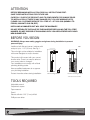
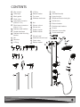
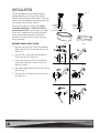
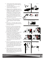
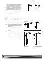
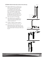
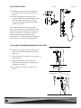
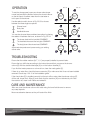
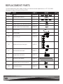
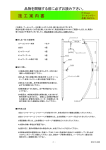
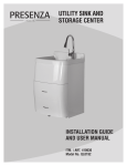
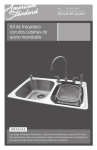
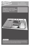
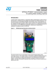
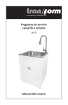
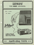
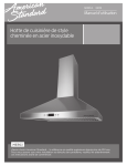
ULTIMATE RAIN
AND MASSAGE
SHOWER SPA
INSTALLATION GUIDE
AND USER MANUAL
Model No.: QB016
ATTENTION
BEFORE BEGINNING INSTALLATION, READ ALL INSTRUCTIONS FIRST.
SAVE THESE INSTRUCTIONS FOR FUTURE USE.
CAREFULLY CHECK THE PRODUCT AND ITS COMPONENTS FOR DAMAGE PRIOR
TO INSTALLATION. IF THERE IS ANY DAMAGE OR IF YOU ARE MISSING PARTS,
PLEASE CALL CUSTOMER SERVICE TOLL FREE AT 1-877-333-0098 (MONDAY TO
FRIDAY, 8:30 AM TO 5:00 PM, EST).
INSTALLING A DAMAGED UNIT WILL VOID THE WARRANTY.
DO NOT RETURN TO THE PLACE OF PURCHASE BEFORE CALLING THE TOLL FREE
NUMBER. DO NOT DISPOSE OF PACKAGING UNTIL YOU ARE SATISFIED WITH YOUR
NEW SHOWER SPA.
BEFORE YOU BEGIN
WARNING: Always wear safety goggles and gloves during installation to prevent
personal injury.
FIG. 1
Installs on both flat and uneven* surfaces with
a step of up to 1 1/2” (38 mm). See Fig. 1.
This unit might not be suitable for installation
with some fiberglass or acrylic showers.
This product will connect with your current
shower valve. There is no need to take out
your current valve or change it.
Your installation must comply with all local
plumbing building codes.
Have a qualified tradesman do or approve
your plumbing installation.
Protect the entire surface during installation.
Flat mounting surface
Uneven mounting surface*
*with tub surround or tiles
TOOLS REQUIRED
Adjustable wrench
Carpenter’s square
Tape measure
Pencil
Electric drill with 0.25" (7 mm) drill bit
Phillips screw driver
CONTENTS
A
Allen wrench
M
L-Fitting
Z
Hose
B
Teflon tape
N
Rubber washer
AA
Handheld bracket
C
Mesh gasket
O
Top cover
BB
Upper body jet
D
Check valve
P
Stainless steel cover
CC
Middle and bottom body jets
E
Q
Nut
R
S
G
Long brass connector
(55mm/2.17in)
Short brass connectors
(28mm/1.1in)
Stainless steel washers
Shower column
Shower arm
T
H
Double sided tape
Rubber washer
U
I
Stainless steel mounting
bracket
Rubber washer
V
Shower head
P
J
Nut
W
Handheld shower head
O
K
Restrictor
X
Check valve
L
L-Fitting
F
Rubber washer
Y
E
A
B
H
I
C
J
D
E
F
M
1
Wall anchors
2
Bottom bracket
3
Stainless steel washers
4
Screws
5
Aluminum cover plate
6
Double sided tape
S
U
N
L
Q
G
V
R
K
W
AA
BB
X
1
5
3
2
4
Y
CC
6
T
Z
INSTALLATION
FIG. 2
This unit is designed to be installed using your
existing plumbing. Your shower valve, diverter
valve or diverter tub spout will be used in its current
position and will operate as it was used before with
your previous shower head. See Fig. 2.
This unit can either be installed with Option
A: Double sided tape or Option B: Bottom
bracket and screws. In both cases, the weight
of the unit is carried by the mounting bracket
[I], the double sided tape [6] or the bottom
bracket [2] to prevent the unit from swinging
during operation.
Existing
shower
valve
Tub spout
SHOWER HEAD INSTALLATION
1. Remove the top cover [O] and the stainless
steel cover [P] f rom the shower column [R].
See Fig. 3.
2. Remove the nut [Q] that is pre-installed in
the shower arm [S]. See Fig. 4.
Diverter
Existing
shower
valve
Diverter
FIG. 3
FIG. 4
P
O
S
R
Q
3. Insert the shower arm [S] into the shower
column [R] and secure it with the nut [Q].
See Fig. 5 and 6.
FIG. 5
FIG. 6
4. Place the rubber washer [N] onto the L-fitting
[M]. See Fig. 7.
S
5. Connect the L-fitting [M] to the shower arm
[S]. See Fig. 8.
S
Q
R
FIG. 7
M
FIG. 8
N
S
M
6.
7.
Check that the rubber washer [U] that is
pre-assembled on the shower head [V] is
not loose. See Fig. 9.
FIG. 9
FIG. 10
U
S
Screw the shower head [V] on to the
shower arm [S]. See Fig. 10.
8. Make sure that your SHOWER VALVE IS
CLOSED AT ALL TIMES FROM NOW UNTIL
TESTING IS REQUIRED. As per Fig. 11
disassemble your existing shower head
(1). Pull away from the wall the cover (2)
that is in the area where the shower arm
(3) meets the wall. Mark clearly on your
existing shower arm, the level at which the
wall meets the shower arm.
9. Remove your existing shower arm (3) from
the wall using a wrench and turning it
counter-clockwise. DO NOT DISCARD
YET.
V
V
FIG. 11
Mark shower
arm here
2 3/16” (55.6 mm)
10. As per Fig. 12, put teflon tape on the end
of the long brass connector [E] that has the
white check valve [D].
11. As per Fig. 13, put your old shower arm
(the one you have just removed) on a flat
surface. Beside it put the longer brass
connector [E] with the teflon tape and
check valve [D] side aligned with the
threaded side of the shower arm.
12. To the end of the long brass connector [E]
(the end that has the hexagonal hole
inside) add, as needed, small (20 mm,
3/4”) brass connectors [F] threading them
in place, until the total length of the brass
connectors assembly is between 5/8” and
1 1/8” (16 mm and 29 mm) longer than the
place where the mark was done on the
shower arm.
E
D
FIG. 13
F
E
Mark on shower arm
This distance should be
between 5/8” and 1 1/8”
F
E
Teflon side
Align here
F
This distance should be F F
between 5/8” and 1 1/8”
13. Using the provided Allen wrench [A], install
the new assembled brass connector as per
Fig. 14, making sure that the end where
you placed the teflon tape (where the check
valve is) goes towards the wall where the
old shower arm was.
14. Clean the wall around the brass connector
assembly thoroughly with a dry cloth. Peel
paper backing from the factory pre-installed
double sided tape [H] on the stainless steel
mounting bracket [I], Fig. 15.
FIG. 12
Teflon tape on this end
This distance should be
between 5/8” and 1 1/8”
F
E
E
F
F
E
F
E
This distance should be F F F
between 5/8” and 1 1/8”
FIG. 14
E
FIG. 15
H
A
Assembled brass
connector
Wall
I
FIG. 16
Place the stainless steel mounting bracket
[I] on the brass connector assembly and
adhere upright to the wall, see Fig. 16.
FIG. 17
I
G
15. As per Fig. 17, secure and tighten the nut
[J] on brass assembly using one or 2 of the
stainless steel washers [G] if required.
J
16. Bracket [I] allows for mounting this unit on
flat walls or on walls that have a shower
surround or tiles with a step of up to
1 1/2” (38 mm).
OPTION A: Double sided tape (for flat walls and walls with surround units or
tiles with a step out of up to 1 1/2”)
17A1. Connect L-fitting [L] to brass connector
assembly using restrictor [K], see Fig. 18.
17A2. With a dry rag, thoroughly clean the wall
between the brass connector and the
shower valve.
Brass Connector
Assembly
FIG. 18
FIG. 19
K L
I
17A3. Peel the paper backing from double
sided tape [6] on back of column, see
Fig. 19.
FIG. 20
17A4. Hang the shower column [R] on the
stainless steel mounting bracket [I]
through holes in column. Position
column vertically level, then apply
pressure to main body to firmly adhere
mounting tape to the wall, see Fig. 20.
With flat wall
With Surround or tile with
a step of up to 1 1/2”
(38mm)
OPTION B: Bottom bracket and screws (for flat walls only)
Fig. 21
17B1. Mark the drill holes Ø 1/4” (0.635 cm) as
shown in Fig. 21. The three holes consist
of two holes drilled side by side, 0.67”
(1.7 cm) apart from the center of each
hole with the center line running between
them. The third hole is drilled on the
center line 0.79” (2 cm) below the first
two holes. The upper two holes should
be drilled below the shower pipe, 22 1/4”
(56.5 cm) from the center of the top two
holes to the center of the inlet pipe.
22 ¼" (56.5 cm)
inlet
0.67" (1.7 cm)
0.79" (2 cm)
17B2. Insert wall anchors [1] in pre-drilled
holes. Secure bottom bracket [2] to the
wall with screws [4] and stainless steel
washers [3], see Fig. 22.
22 ¼" (56.5 cm)
17B3. Connect L-fitting [L] to brass connector
assembly using restrictor [K], see Fig. 23.
17B4. Hang shower column bottom [R] on the
bottom bracket [2] first, then hang the shower
column [R] on stainless steel mounting bracket
[I] through the holes in the shower column, see
Fig. 24.
Fig. 22
inlet
0.67" (1.7 cm)
0.79" (2 cm)
Fig. 23
K
L
I
R
Fig. 24
I
R
2
FINAL INSTALLATION
18. Replace top cover [O] and the stainless
cover [P] on the shower column [R], see
Fig. 25.
19. Attach long flexible shower hose [Z] to
colum body [R] and handheld shower head
[W] with rubber washers [Y],[T]. Check
valve [X] comes pre-installed in handheld
shower, see Fig. 26.
FIG. 25
FIG. 26
P
O
R
W
Y
NOTE: Make sure that none of the hoses
are bent or kinked after final installation. Check
water connections for proper flow; make sure
there are no leaks. Do not forget to use the
rubber washers to prevent leaks on the
connections. If you find that the water pressure
or volume is low, clean the mesh gasket [C].
T
Z
IF YOU HAVE A SHOWER SURROUND OR TILE STEP
FIG. 27
20. Measure the length of the gap between the
top of the shower panel and the surround,
see Fig. 27.
21. Cut both aluminum covers [5] with scissors to
desired length.
22. Take off the paper from the aluminum
plates [5] then stick them on the gap from
the panel to the wall.
23. Stick aluminum covers [5] in place, see
Fig. 28.
5
FIG. 28
5
5
OPERATION
To use the shower panel, open your shower valve (as per
normal use) and flip the diverter valve on the shower valve or
on the tub spout to redirect water from the toe tester or
tub’s spout to the shower.
FIG. 29
1
Selector
switch
Use the selector switch shown in Fig. 29-30 to choose
between the three single use options:
1
Shower head
2
Body Jets
3
Handheld shower
FIG. 30
2
FIG. 31
Selector
switch
FIG. 32
4
Selector
switch
Selector
switch
3
You can also choose three combined use options by placing
the selector in between the icons, as shown in Fig. 32-34:
4
The shower head and the handheld COMBINED
5
The handheld shower and the body jets COMBINED
6
The body jets and the shower head COMBINED
Adjust water temperature and pressure using your existing
shower valve.
FIG. 33
FIG. 34
6
Selector
switch
Selector
switch
5
TROUBLESHOOTING
Ensure that the rubber washers [N, T, U, Y] are properly installed to prevent leaks.
Ensure that you drill holes according to the instructions and that you secure the shower
column [R] with the double-sided tape [6] or on the bottom bracket [2].
If you find that water pressure or volume is low, clean the mesh gasket [C].
If there is no water flow, check the brass connector [E] to make sure that it has not been installed
reversed. Check step 10 & 13 of the installation guide.
If the check valve [D] is installed correctly but there is still no water, take the shower column [R]
off the wall, loosen the L fitting [L] and check that the restrictor [K] is not blocked by dirt. Take
the restrictor off, clean it with water and reinstall it.
CARE AND MAINTENANCE
After use, rinse the shower column with water using the hand held shower to remove
any soap deposits.
Never use abrasive cleaners as they will scratch the finish.
REPLACEMENT PARTS
To order replacement parts, please contact our customer service department at 1-877-333-0098
(Monday to Friday, 8:30 am to 5:00 pm, EST).
Contents
Part #
PART
PART #
3
Screws
QHB100
3
4
Stainless steel washers
QHB101
3
1
Wall anchors
QHB102
3
2
Bottom bracket
QHB103
1
Y
Rubber washer for hand held shower
QHB104
1
U
Rubber washer for shower head
QHB105
1
Z
Shower hose
QHB106
1
V
Shower head
QHB107
1
BB
Upper body jet
QHB108
1
CC
Middle and bottom body jets
QHB110
2
W
Hand held shower head
QHB111
1
E
Longer brass connector
QHB114
1
5
Aluminum cover plates
QHB116
2
I
Stainless steel mounting bracket
QHB115
1
Handheld bracket
QHB112
1
AA
IMAGE
QTY
1-YEAR WARRANTY
This unit is warranted to the original purchaser to be free of defects in material and workmanship
for one (1) year from the date of purchase. Conglom Kitchen & Bath will repair or replace, at its
option, the unit or its equipment in accordance with the following terms and conditions.
WARRANTY LIMITATIONS
Our warranty does not cover defects, damage, or failure caused by the common carrier, installer,
user, or other person, or resulting from, without limitation, any of the following:
• Careless handling (lifting unit by plumbing, abrading finish, etc.).
• Modification of any type for any reason (including modification to meet local codes).
• Improper installation (including installation not in accordance with instructions and specifications
provided with the unit).
• Connections supplied by the installer of the equipment.
• Misuse, incorrect operation, or lack of proper routine maintenance.
• Operation of the unit without specified minimum amount of water or at inappropriate water
temperature
• Use of abrasive or improper cleaners
• Force majeure, such as lighting, floods, earthquakes, etc.
In addition, Conglom Kitchen & Bath WILL NOT BE RESPONSIBLE FOR INCIDENTAL OR
CONSEQUENTIAL DAMAGES or losses arising from any cause (e.g., water damage to carpet,
ceiling, loss of use, etc.) including its own negligence; damages to, respecting, or resulting from
plated parts when chemicals are used in or on the unit; optional equipment not manufactured by
Conglom Kitchen & Bath; or defects that should have been discovered before installation. This
limited warranty does not include labor, transportation, or other costs incurred in the removal
and/or reinstallation of the original unit and/or installation of a replacement unit; any costs relating to
obtaining access for repair; or loss of use, including loss of sales, profit or business advantage of
any kind under any circumstances.
This warranty does not extend to commercial or institutional use or installation.
It is the responsibility of the installer/owner to determine specific local code compliance prior to
installation of the product. Conglom Kitchen & Bath makes no representation or warranty
regarding, and will not be responsible for any code compliance. Conglom Kitchen & Bath does not
warrant connections of water supply fittings and piping, or fill systems. Nor is it responsible for
damage to the shower panel which occurs during any installation procedure.
WARRANTY CLAIM PROCEDURE
If a claimable defect occurs, please fill out a claim form through our website at
www.conglomkb.com or contact our customer service department at 1-877-333-0098
(Monday to Friday, 8:30 am to 5:00 pm, EST).
Before you make your claim call, please make sure you have:
1. The description of the product.
2. Proof of sale.
3. Details regarding the defect.
4. Name and address of the owner and installer.
Claims must be filled out in writing and returned within six (6) months of appearance of defect.
Failure to comply with this stipulation will render the warranty null and void. We reserve the
right to a thirty-day (30) delay following receipt of claim in which to inspect the product. We
assume no responsibility for labor costs or removing/replacing a previously installed product
or transportation or return of a product.
Imported by:
St. Laurent, Quebec, H4S 2C3
1-877-333-0098
www.conglomkb.com
Made in China