1
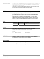
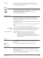
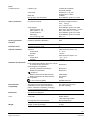
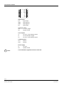
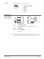
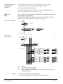
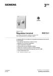
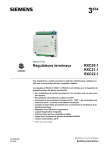
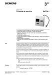
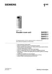
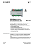
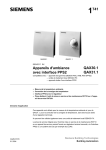
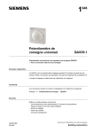
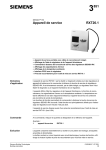
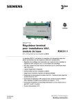
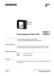
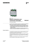
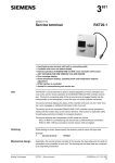
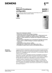
3 830 Desigo™ RXC Room controller RXC10.1 RXC10.5 for chilled ceilings, radiators, and VAV applications with LONMARK®-compatible bus communications The RXC10 room controller is used for temperature control in individual rooms. For chilled ceilings, radiators, and VAV applications PI or PID control (dependent on application) Downloadable application software LONMARK®-compatible bus communications Integrated into the Desigo building automation and control system Control of thermic valve actuators, AC 24 V, PDM 1 Operating voltage AC 24 V 1) PDM = pulse/duration modulated Application The RXC10 room controller is optimized for the control of chilled ceilings, radiator-type heating, and VAV applications at individual room level. The controller application is determined by downloadable application software, also referred to simply as the “application”. The various applications and the associated functions are described in detail in the Desigo RXC applications library (V1: CA2A3810, V2:CA110300). The controllers are delivered pre-loaded with basic application 00010. The basic application, which contains only I/O module functions, is overwritten with the definitive application in the commissioning phase. The RXT10 commissioning and service tool is used for this purpose (see “Commissioning”). CA2N3830en_05 2013-06-16 Building Technologies Use as an I/O module In conjunction with a building automation and control system, the RXC10 controller can also be used as a universal input module, e.g. to register the room temperature from digital signals or a setpoint reset unit. In this case, the controller is loaded with basic application 00010. The inputs can then be interrogated via the building automation and control system. Functions The controller functions are determined by the selected application and its parameters, and by the input/output configuration. For a detailed description of functions, refer to the Desigo RXC applications library. (V1: CA2A3810, V2:CA110300). When Desigo RXC is integrated into a building automation and control system, additional functions become available, such as time scheduling, central control of setpoints etc. (refer to the Desigo INSIGHT documentation for further information). Types Product No. RXC10.5/00010 Stock number S55373-C110 Designation Room controller Ordering When ordering, please specify the quantity, product name, type code and application.The controller is loaded with basic application 00010. Example: 30 Room controllers RXC10.5/00010 Compatibility The RXC10 controller can be used in conjunction with the Siemens field devices. For details, refer to the RX hardware overview, CA2N3804. Mechanical design The RXC10 controller comprises a housing base with connection terminals and a cover incorporating the printed circuit board and the operator controls. The controller also has a tool socket, a service LED and a service pin. 2/12 Siemens Building Technologies RXC10 – Room controller CA2N3830en_05 2013-06-16 00103 A Cover Dial for continuously variable adjustment of the setpoint Housing base with connection terminals Comfort button (OFF / AUTO) 00022 A Socket for RXT10 commissioning and service tool Service terminal RXT20.1 can not be connected (no PPS2 interface). Service pin Service LED (yellow) Terminal cover View from below The connection terminals are located in the housing base. To connect the terminals, the housing cover must first be removed (see diagram below). 00020 00104 A Label (connection terminals) Connection terminals 3/12 Siemens Building Technologies RXC10 – Room controller CA2N3830en_05 2013-06-16 Label (inside housing) Bar code, Code 128 (Identification number of Neuron chip) Identification number of Neuron chip Protection standard Test date, series (Z, A, B, C…) Location Preloaded application (example) Note Definitive application loaded Options for use of the labelling fields “Appl.” and “Loc.”: Hand-written entry of the location and the loaded application ... or Printed adhesive label (printed from the RXT10 commissioning and service tool) Connection terminals The two rows of terminals are slotted into the housing base (see the diagram “Terminal cover”). They can be removed to facilitate connection. Communication The RXC10 controller communicates with other devices via the following interfaces: LONWORKS® bus (terminals CLA and CLB) for communication with: PXR system controller or NIDES.RX interface (to Desigo) Other Desigo RXC devices LONMARK®-compatible 3rd party devices (e.g. presence detector) Tool socket (RJ45) on the controller, for: RXT10 commissioning and service tool (LONWORKS® bus) LONWORKS® bus The following diagram shows the wiring of the LONWORKS® bus and interface to the RXT10 commissioning and service tool. CLA CLB LonWorks® Bus RXC10 LonWorks® 3830 A01 Tool LonWorks® RXT10 Service LED The yellow service LED shows the current operational status of the controller by means of different flashing patterns (see the RXT10 user manual, CM110669). 4/12 Siemens Building Technologies RXC10 – Room controller CA2N3830en_05 2013-06-16 Service pin The service pin is used to identify the controller in the commissioning phase. When the pin is pressed, the controller’s identification number is transmitted to the RXT10 commissioning and service tool. Disposal The devices are classified as waste electronic equipment in terms of the European Directive 2002/96/EC (WEEE) and should not be disposed of as unsorted municipal waste. The relevant national legal rules are to be adhered to. Regarding disposal, use the systems setup for collecting electronic waste. Observe all local and applicable laws. Engineering notes The Desigo RXC installation guide, document CA110334, contains the relevant engineering information for the LONWORKS® bus (topology, bus repeaters, bus termination etc.) and for the selection and dimensions of connecting cables for the supply voltage and field devices. The controller operates with an AC 24 V supply voltage. Connected valves are supplied directly from the controller. This device has no circuit breakers for supply lines to external consumers (field power supply)! Line insulation must always be sufficient for the available rated voltage. Caution AC 24 V triac outputs When forwarding supply voltage (for 24 V low voltage as well) to external consumers, the wiring cross sections must at any rate be adapted to the preswitched overcurrent protection device. Please comply under all circumstances with local regulations. The simultaneous load on outputs Y1 and Y2 must not exceed 9.5 VA. Example: Y1 (heating) 2 thermic valve actuators, type STP72E 6 W Y2 (cooling) 2 thermic valve actuators, type STP72E 6 W The maximum load is 9.5 VA for the heating sequence and 9.5 VA for the cooling sequence. This is acceptable because the two sequences never operate at the same time. Mounting The mounting instructions are printed on the controller packaging, together with a drilling template. STOP Caution! The unit is not protected against accidental connection to AC 230 V. Commissioning The RXC10 controller is commissioned with the RXT10 commissioning and service tool. For this purpose, the RXT10 is connected to the LONWORKS® bus via the tool socket on the controller. The commissioning procedure for the entire Desigo RXC range is described in detail in the RXT10 user manual, document CM110669. 5/12 Siemens Building Technologies RXC10 – Room controller CA2N3830en_05 2013-06-16 Labeling Function test The labeling fields “Appl.” and “Loc.” are used to indicate the application actually loaded and the location of the controller, either in writing or by use of printed adhesive labels (see “Label” under “Mechanical design”). With all applications (including basic application 00010), the inputs can be interrogated and the outputs overridden using the RXT10 commissioning and service tool. Technical data Power supply Caution! Operating data Inputs Signal inputs D1, D2 (for volt-free contacts) Outputs Triac ouptuts Y1, Y2 Control output YC1 Operating voltage Rated voltage Frequency Power consumption Internal fuse External fuse SELV / PELV AC 24 V ± 20% AC 24 V 50/60 Hz Max. 2 VA + external load None Transformer with secondary limitation of max. 10 A or External secondary power fuse with max. T 10 A non-renewable fuse or max. C 13 A circuit breaker is required in all cases Control algorithm Temperature sensor Measuring range Response time Measuring accuracy (25 °C) Measuring accuracy (0 … 30 °C) Setpoint correction Correction range Accuracy over full correction range PI or PID NTC resistance sensor 5 … 40C 8 min 0.25 °C 0.5 °C Quantity Contact voltage Contact current Contact transfer resistance Contact insulation resistance Not suitable for pulse control 2 Approx. DC 30 V (pulsed) Approx. DC 10 mA (pulsed) Max. 100 Min. 50 k Quantity Output voltage Load current per triac Total nominal load (with load at both outputs simultaneously) Internal fuse 2 AC 24 V ON/OFF, PDM or 3-position (depending on application parameters) Max. 0.5 A Max. 9.5 VA (e.g. 2 thermic valves, type STE72 per heating and cooling sequence 2 A (both outputs together) Quantity Nominal voltage range Overrange Resolution Output current Response time 1 DC 0 … 10V 0.5 V 8 bits (50 mV) Max. 1 mA 100 ms max. 12 K (default 3 K) 10% 6/12 Siemens Building Technologies RXC10 – Room controller CA2N3830en_05 2013-06-16 Ports LONWORKS® bus Interface type Transceiver Baud rate Bus topology, bus termination Cable connections Connection terminals LONMARK®-compatible, electrically isolated On RXC10.1: FTT-10A On RXC10.5: FT 5000 78 kBit/s See installation guide, CA110334 Cable lengths Signal inputs D1, D2 Triac outputs Y1, Y2 LONWORKS® bus Cable type Tool connecting cable Stranded or solid conductors 0.25 … 2.5 mm2 or 2 x 1.5 mm2 solid See installation guide, CA110334 Max. 100 m with diameters 0.6 mm Max. 100m where A 1.5 mm2 See installation guide, CA110334 See installation guide, CA110334 Max. 3 m Housing protection standard Protection standard to EN 60529 IP30 Protection class Insulation protection class III Ambient conditions Operation Temperature Humidity Transport Temperature Humidity Class 3K3 to IEC 60721-3-3 5 ... 40 °C < 85 %rh Class 2K3 to IEC 60721-3-2 – 25 ... 65 °C < 95 %rh Standards and directives Product standard Automatic electronic controls for household and similar use Electromagnetic compatibility Immunity (industrial & residential) Emissions (residential) compliance Meets requirements of EMC directive Meets requirements of RoHS directive UL compliance C-Tick conformity (EMC) Environmental compatibility The product environmental declaration CA2E3830 contains data on RoHS compliance, materials composition, packaging, environmental benefit, disposal Dimensions See dimension diagrams Color Front plate Weight EN 60730-1 EN 60730-1 EN 60730-1 2004/108/EC 2011/65/EU UL316 AS/NZS 61000-6-3 ISO 14001 (Environment) ISO 9001 (Quality) Housing base and mounting plate NCS S 0502-G RAL 9003 signal white RAL 7035 light grey Weight excluding packaging 0.16 kg 7/12 Siemens Building Technologies RXC10 – Room controller CA2N3830en_05 2013-06-16 Connection terminals 00109 G D1 G0 GND YC1 Y1 GND D2 G CLA Y2 CLB Signal inputs D1 Signal input GND Signal ground GND Signal ground D2 Signal input Analogue output YC1 0 … 10 V output G0 System neutral Triac outputs Y1 AC 24 V, 0.5 A switching output G AC 24 V actuator supply Y2 AC 24 V, 0.5 A switching output LONWORKS® bus CLA Data A CLB Data B Power supply G AC 24 V G0 System neutral STOP Note! Local installation regulations must be observed. 8/12 Siemens Building Technologies RXC10 – Room controller CA2N3830en_05 2013-06-16 Tool socket Standard RJ45 tool socket for LONWORKS® devices. 1 2 3 4 5 6 7 8 3206Z01 12 345 678 LONWORKS®, Data A (CLA) LONWORKS®, Data B (CLB) Not used Not used Not used Not used Not used Not used Connection of field devices, LONWORKS® bus and supply voltage AC 24 V 0 ... 10 V CLA CLB D1, D2 G G0, GND Y1, Y2 YC1 G D1 G0 GND YC1 GND Y1 D2 G CLA Y2 CLB 3830A02 Connection diagrams LonWorks® Bus LONWORKS® data cable + LONWORKS®data cable – Volt-free contacts (window contact, occupancy detector etc.) AC 24 V phase System neutral AC 24 V triac output 0 … 10 V analogue output Twisted pair Note For information on compatible actuators for the RXC10 controller, refer to the relevant application description. See Applications library (V1: CA2A3810, V2:CA110300). 9/12 Siemens Building Technologies RXC10 – Room controller CA2N3830en_05 2013-06-16 Parallel connection of several thermic actuators Up to 2 thermic actuators can be connected directly to the room controller. In the case of more than 2 actuators a power amplifier is required. The same principle applies to outputs Y2. Note that the simultaneous load on outputs Y1 and Y2 must not exceed 9.5 VA. Power consumption at input X1 of the UA1T: 0.5 VA. STOP Mixed operation: Connecting thermic actuators to the controller as well as to the power amplifier is NOT allowed. Differing voltage of the power supply of the controller and the supply of the power amplifier may cause big differences in the position of the valves. Note! N1 Connection to controller 00105 D G G AC 24 V G0 G0 Y1 Y1 G Connection to power amplifier N1 AC 24 V AC 24 V G G0 G G0 Y1.1 00105 E G G0 Y1 Y1 G N2 1 NS COM 8 2 LS Y1 7 3 COM COM 6 4 X1 Y1 5 1 NS COM 8 2 LS Y1 7 3 COM COM 6 4 X1 Y1 5 N2 N1 N2 Y1 Y1.1 Notes Y1.1 Y1.3 Y1.2 Y1.4 Y1.5 Y1.7 Y1.6 Y1.8 RXC10 UA1T (see data sheet CA2N3591) AC 24 V thermic valve actuator AC 24 V thermic valve actuator (max. 2 STA72E / STP72E actuators per Y1 output on the UA1T) The UA1T requires an AC 24 V supply voltage The UA1T is not suitable for the connection of 3-position actuators. 10/12 Siemens Building Technologies RXC10 – Room controller CA2N3830en_05 2013-06-16 Dimensions 40 All dimensions in mm 126 00023 92 34 4,2 00024 78,5 56 60 Drilling diagram (1:2) 56 60 11/12 Siemens Building Technologies RXC10 – Room controller CA2N3830en_05 2013-06-16 12/12 2009 - 2013 Siemens Switzerland Ltd. Siemens Building Technologies RXC10 – Room controller Subject to change CA2N3830en_05 2013-06-16