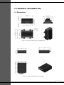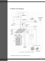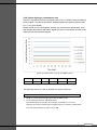
1
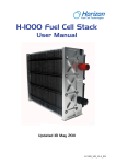
 User
Manual
H-1000XP Fuel Cell System
. Date:2011‐03‐29 Part Number:H‐1000XP Version:20110329 1 Revision History
Release No.
Date
Revised by
Revision Description
Rev. 0
12/13/10
Tony
User’s Manual draft
Rev. 0.9
12/24/10
WRP
1.
2.
3.
4.
5.
Modified PART LIST
Modified GENERAL INFO
Modified SYSTEM SET UP
Modified SOFTWARE
Added MAINTENENCE
Rev. 0.95
01/13/11
WRP
1.
2.
3.
4.
Modified SAFETY
Modified SOFTWARE
Modified MAINTENANCE
Added TROUBLESHOOTING
Rev. 0.96
01/19/11
WRP
1.
Modified Ultra Capacitor Bank
Rev. 0.97
02/10/11
WRP
1.
2.
Added note to Stack Holder
Added note to Hydrogen Sensor
Rev. 0.98
02/25/11
WRP
1.
Modified Software Installation
Rev. 0.99
03/29/11
WRP
1.
2.
Added H2 sensor external power
Added fuse usage to Step 7 & 11
2 OVERVIEW OF THE SYSTEM
Thank you for choosing our fuel cell stack. The Horizon fuel cell stack is an
air-cooled, light weight and compact fuel cell stack.
H-1000XP is specially developed for SHELL Eco-marathon event,(please refer to
www.shell.com/ecomarathon/ for more details), this system has been designed
according to event rules, it only needs a start up battery(12V) to start the system and
will be self-sustainable after that, some of the features may not be necessary for other
applications, please contact HORIZON for more details
Please read all instructions carefully prior to product use and keep this manual for
future reference.
Further copies can be obtained from Horizon Fuel Cell Technologies or by emailing:
[email protected]
Please refer to the Horizon website for latest information: www.horizonfuelcell.com
Actions that will void the fuel cell and controller warranty:
● Do not attempt, under any circumstance, to disassemble or inappropriately tamper
with the fuel cell.
● Operate the fuel cell with a controller not designed and built by Horizon for the
specific fuel cell.
● Operate the fuel cell with valves and blowers that are not provided by Horizon for
the specified fuel cell and controller.
● Disassemble the fuel cell
● Disassemble the controller
● Operating the fuel cell and controller that is no that is not in the setup and/or
specified in the user manual provide for the specific product.
IMPORTANT
In order for the warranty to come into effect the stack must be registered on the
Horizon Warranty Page at: www.horizonfuelcell.com/warranty.htm
Disclaimer
Information contained in this data sheet is considered to be accurate and reliable, to the best of our
knowledge, at time of printing. However, we do not guarantee or warrantee its accuracy, reliability or
completeness. Information may be subjected to revision and edition at our discretion. It is the User’s
obligation to use the product safely and within the scope advised in this publication. Information
relates only to the specific product/material mentioned and may not be applicable where such
product/material is used with any other.
3 Table of Content
1.0
2.0
3.0
4.0
5.0
6.0
7.0
Safety…………………………………………………………6
Part list………………………………………………………12
General information…………………….……….…………18
System set up……………………………………………….27
Software …………………………………………………….41
Maintenance………………………………………….….….46
Troubleshooting ……………………………………….……49
4 Terminology
PEM fuel cell:
A PEM (Proton Exchange Membrane) fuel cell is a device that converts hydrogen
and oxygen into water and electricity.
A fuel cell stack:
It includes a plurality of plate-like fuel cells arranged along an axis generally
parallel to cell thickness with electrically conductive separator plates between
each pair of cells.
Reactants:
Reactant is a material used to start a chemical reaction. In the fuel cell the
reactants are air and hydrogen by which the electricity will be generated.
Humidification:
Humidity what the fuel cells need for running.
Blower:
Supply air to the fuel cells and meanwhile decrease the temperature in the stack.
Purging valve:
The controller will control the purging time for purging the water and air gas
redundant in the fuel cells.
SCU:
Short circuit unit – the short circuit will be controlled for good performance of the
stack.
Dead ended valve:
Purge valve for the controlling of the gas purging.
Mass flow per minute:
The total amount of the hydrogen flow through the fuel cell every minute what the
hydrogen supply can be calculated.
HFCT:
Horizon Fuel Cell Technologies 5 1.0 SAFETY
6 1.0 SAFETY
NOTE: The safety guidelines included here may not cover every
situation. Use common sense.
1.1 General Information
For this unit to generate electrical power, a supply of hydrogen fuel is necessary.
It is important for any operator to be aware of, understand, and follow all local
safety requirements related to the handling of hydrogen and compressed gases.
The fuel cell system has built-in safeguards and is designed to shut down
automatically if any out-of-range operating condition occurs. Possible situations
include low cell voltage, high current, high temperature, or hydrogen leak
detection.
• Do not dismantle the H-1000XP system. Contact HORIZON if you have any
concerns about operation.
1.2 Using Hydrogen
WARNING! FIRE OR EXPLOSION
Keep all sources of ignition away from hydrogen.
This unit uses hydrogen fuel. Hydrogen is a colorless, odorless and flammable
substance. It is highly combustible in the presence of oxygen and burns with a
colorless flame.
Leaking gas may be hot and pose a burn danger. Stop the flow of gas – if you are
not in danger – and use water to cool the area. If fire occurs, do not attempt to
extinguish flames, allow the fire to burn out.
Prevent overexposure to hydrogen. Hydrogen is non-toxic but can act as a simple
asphyxia by displacing the oxygen in the air. There are no warnings before
unconsciousness results. When operating the H-1000XP power module in an
enclosure:
• Ensure ventilation slots are clear and unobstructed at all times during operation
• Operate within the temperatures limits stated on the H-1000XP system
nameplate
• Never operate if an alarm condition exists
1.3 Handling Compressed Gas Cylinders
WARNING!
Do not handle compressed hydrogen gas cylinders without
training or experience.
7 • Use a pressure regulator to control the fuel inlet pressure to the system.
• Do not alter the fitting on a regulator. Ask experienced personnel for help.
• Do not attempt to force gas cylinder threads.
• Never transport a gas cylinder with regulators attached. Ensure cylinder caps
are in place. Always use a cylinder cart with a safety strap or chain.
• Secure a high-pressure cylinder to a bench, post, or fixed object to avoid
accidental contact.
• Avoid unnecessary contact with On/Off valves. They can easily move to “On” by
accident.
1.4 Hydrogen Leakage
Hydrogen is colorless, odorless and tasteless. Hydrogen is non-toxic but can act
as a simple asphyxiated by displacing the oxygen in the air. There are no warning
symptoms before unconsciousness results.
WARNING!
Inhaling hydrogen can lead to unconsciousness and asphyxiation.
Hydrogen molecules are smaller than any other gas, making hydrogen more
difficult to contain. It can diffuse through many materials considered airtight. Fuel
lines, non-welded connections, and non-metal seals such as gaskets, O-rings,
pipe thread compounds and packings present potential leakage or permeation
sites. Furthermore, hydrogen’s small molecule size results in high buoyancy and
diffusivity, so leaked hydrogen will rise and become diluted quickly.
Constant exposure to hydrogen causes hydrogen embrittlement in many
materials. The mechanisms that cause hydrogen embrittlement effects are not
well defined. Factors known to influence the rate and severity of hydrogen
embrittlement include hydrogen concentration, hydrogen pressure, temperature,
hydrogen purity, type of impurity, stress level, stress rate, metal composition,
metal tensile strength, grain size, microstructure and heat treatment history.
Moisture content in the hydrogen gas may lead to metal embrittlement through the
acceleration of the formation of fatigue cracks. Hydrogen embrittlement can lead
to leakage or catastrophic failures in metal and non-metallic components.
As a preventative measure, H-1000XP must be operated in a well-ventilated area
in order to inhibit potential hydrogen accumulation.
WARNING!
Always operate H-1000XP in a well-ventilated area and ensure that
ventilation slots are unobstructed.
8 1.5 Flammability and Volatility
Hydrogen is flammable over concentrations of 4 – 75% by volume in air, and is
explosive over concentrations of 15 – 59%. As a result, even small leaks of
hydrogen have the potential to burn or explode. Leaked hydrogen can
concentrate in an enclosed environment, thereby increasing the risk of
combustion and explosion.
Hydrogen flames are pale blue and are almost invisible in daylight due to the
absence of soot. Due to its high buoyancy and diffusivity, burning hydrogen rises
unlike gasoline, which spreads laterally.
A flammable or explosive hydrogen mixture is easily ignited by a spark or even a
hot surface. The auto-ignition temperature of hydrogen is 500 °C (932 °F). The
energy of a hydrogen gas explosion is 2.4 times that of gasoline or methane for an
equal volume. Hydrogen gas explosions are therefore more destructive and carry
further.
WARNING!
A mixture of hydrogen and air is potentially flammable and
explosive and can be ignited by a spark or a hot surface.
As in the presence of any fuel, all sources of ignition, including smoking, are not
permitted in the vicinity of the system.
WARNING!
Keep all sources of ignition away. Smoking is not permitted in the
vicinity of the H-1000XP
1.6 Oxygen Depletion
Oxygen is a colorless, odorless, non-toxic and tasteless gas. Oxygen is essential
for life in appropriate concentrations.
Ambient air contains up to 21% oxygen. Oxygen levels below 19.5% are
biologically inactive and may act as simple asphyxiates. Effects of oxygen
deficiency may include: rapid breathing, diminished mental alertness, impaired
muscular coordination, faulty judgment, depression of all sensations, emotional
instability, and fatigue. As asphyxiation progresses, nausea, vomiting, prostration,
and loss of consciousness may result, eventually leading to convulsions, coma,
and death. At concentrations below 12%, immediate unconsciousness may occur
with no prior warning symptoms.
9 WARNING!
Lack of oxygen can lead to unconsciousness and asphyxiation.
As a preventative measure, H-1000XP must be operated in a well-ventilated area
in order to compensate for the oxygen used within the fuel cells.
WARNING!
Always operate H-1000XP in a well-ventilated area.
1.8 Electrical Safety
WARNING!
Avoid contact with an exposed fuel cell stack. Electrical shock can
cause personal injury or death.
• Do not touch fuel cell plates or any electrical components at any time. A running
fuel cell stack is a potential electrical hazard that can cause burns or electrical
shock.
• Do not wear conductive metallic items when you are close to an exposed fuel
cell stack.
• Minimize static discharge at all times If possible, ground all equipment to your
common ground.
• Minimize conductivity. Avoid contact with surfaces that are in contact with water
or gases. Do not operate or store in wet or damp conditions.
• Never use damaged extension cords.
H-1000XP generates up to 48 VDC (open circuit voltage). This voltage decreases
as current is drawn from the module. This voltage is exposed at the output power
connections. These low voltages may constitute a shock hazard and can damage
electronic components if shorted. Therefore, do not touch individual fuel cells, cell
voltage monitoring equipment or electrical components.
WARNING!
Do not touch fuel cells, cell voltage monitoring equipment or
electrical components.
Electronic components can also be damaged as the result of static discharge. To
minimize this, ground all equipment in contact with H-1000XP. Never use
damaged extension cords. Minimize conductivity by avoiding surfaces in contact
with water; hands and clothes must be dry. Do not operate or store H-1000XP in
wet or damp conditions.
10 WARNING!
Minimize static discharge. Ground all equipment.
Residual reactants within the H-1000XP can develop a charge in a matter of
minutes when turned off. A reading of zero volts across the entire power module
does not guarantee that all fuel cells are uncharged.
NOTE: The cathode has already been connected to
the stack shell.
The stack cathode should be connected to common ground of
all the equipments.
WARNING!
Always assume that the fuel cell stack is charged.
Jewellery (such as rings, necklaces, bracelets and watches) may concentrate an
electric current when it comes into contact with charged components, or when a
shock passes through the human body. Accordingly, no jewellery should be worn
near H-1000XP.
1.9 High Temperature
The fuel cell stack is designed to operate above 60ºC sometimes, At this
operating temperature, the air exhaust stream temperature can reach 55ºC and
the cooling air stream can reach 17ºC above ambient conditions. These
temperatures are sufficient to cause burns or severe discomfort. Accordingly,
avoid contact with the fuel cell stack, or components that convey process or
cooling air.
WARNING!
Avoid contact with the fuel cell stack or components that convey
process or cooling air. 11 2.0 PART LIST
12 2.0 PART LIST
1. Stack
The H-1000XP fuel cell stack is a cathode-cooled proton
exchange membrane (PEM) fuel cell stack designed to
provide stable electrical power while operating on air and dry
hydrogen. With innovative materials, the H-1000XP achieved
1000W power output with less weight and more compact size
compare to standard H1000. Tube size for hydrogen
connector Φ6
2. Stack holder
It helps to fix the fuel cell stack on the place you want.
There are 4 in the package. As showed on stack picture
above, each side (left or right) can place 2.
NOTE: Please use bolts provided together with
spring washer. Do not over tighten. The use of
wrong screw length will damage the stack.
4. Hydrogen supply valve
Supply valve controls the H2 input. When the controller
turns on, also the H2 supply valve does. When system
turns off, it is in the off position for preventing the leakage.
Please note the label and the direction of the arrow.
Tube size for hydrogen connector Φ6
3. Hydrogen purging valve
Purging valve: the controller will control the purging time
For purging the water and air gas redundant in the fuel
cells.
Please note the label and the direction of the arrow.
Tube size for hydrogen connector Φ6
13 5. SCU switch
It is to turn the SCU on/off. For SCU, Please refer to Terminology. 6. LCD display
It displays the system status, current, voltage, temperature
etc.
Please refer to trouble shooting section for more details
7. Hydrogen sensor
It triggers at 25% of LFL, which is 1% hydrogen
concentration.
NOTE: This sensor has a delayed respond (for
about 15 seconds).
8. Start up battery connector
It is the connector which connect startup battery to the controller 14 9. Ambient temperature sensor
It senses the ambient temperature.
The sensor should be place opposite to the blower side of
the fuel cell stack. As is showed in system set up section.
10. DC/DC converter
The DC/DC will regulate the output voltage for the controller. It can step down the stack voltage (27.5V to 48V) to 12V for the fuel cell controller and other peripheral parts. 11. Ultra capacitor bank
It can supply power output during system short‐circuiting (please refer to Short Circuit Unit for more details), which could enable system continuous operation without external power supply Rated voltage: 50V Capacitance: 1.25F If regenerative braking is required, please put a bigger ultra capacitor bank to store this energy. If a higher capacity ultra capacitor is used, you can replace this set of capacitors. (Please note that the maximum voltage of the fuel cell is 48V, so size your ultra capacitors accordingly). 15 Control signal connector
Power cord connector
System output connector
Ultra capacitor connector
DC/DC connector
Start up battery connector
Emergency stop switch
RS 232 connector
On/OFF switch
Hydrogen sensor connector
Status LED
LCD display socket
12. System controller
It controls the stack and all peripheral parts to perform at its
optimal condition. It has the following features
z Control Stack temperature
z Control Stack purge rate
z Monitoring stack current and voltage
z Monitoring H2 concentration(H2 sensor needed)
z Protect stack from possible failures, like stack low
voltage, over current, over temperature
z Control Hydrogen supply and shut off
z RS232 Communication with computer
16 Controller Signal Connector from Controller box at the wire side:
Wire colors Connector pin #
Peripherals controlled Red Grey Red & Black Black Yellow Blue Red & Black Black Black #1 & #2 #3 & #4 #5 & #6 #7 & #8 #9 & #10 #11 & #12 #13 & #14 #15 #16 Stack Temperature Sensor Ambient Temperature Sensor Blowers (Red #5= +ve, Black #6= ‐ve) Hydrogen Purge Valve (Black #7= +ve, Black #8= ‐ve) Hydrogen Supply Valve (Yellow #9= +ve, Yellow #10= ‐ve)
Short Circuit Switch N/A N/A Blower PWM Table 2.1 Controller Connector 17 3.0 GENERAL
INFORMATION
18 3.0 GENERAL INFORMATION
3.1 Dimensions
3.0 GENERAL
INFORMATION
Figure 3.1.1 Views and dimensions of H‐1000XP stack Figure3.1.2 Views and dimensions of controller 19 3.2 General specification
Physical
Category
Value
Type of fuel cell
PEM
Number of cells
50
Dimensions
264mm x 197mm x 117mm
Mounting
4 x M6
Weight
Performance
Fuel
operation
Monitoring
stack less than 3.6kg
system less than 5.5kg
Peak power
1100W
Rated current
0 - 33.5A @ 30V
DC voltage
25V - 48V
Reactants
Hydrogen and Air
Composition
99.99% dry H2
H2 pressure
7.2 - 9.4 PSI
Hydrogen consumption
@1000W
13.5SLPM
External temperature
5 - 35°C
Max stack temperature
65°C
Humidification
Self-humidified
Cooling
air
Relative humidity
10%-95%RH non-condensing
Start up battery
12V
RS232
System status / Historical data
Chart 3.2 General Specification of H‐1000XP 20 3.3 Electric Circuit Diagram
Figure 3.3 Electric Circuit Diagram for H‐1000XP Please refer to section 2.0 for more details of each part
21 3.4 H-1000XP Performance Specifications
The H-1000XP can deliver up to 33A of current. Its operating voltage ranges from
46V (no load) to 30V (full load). The rated operating point of 33A@30V is
recommended.
NOTE: All the performances are under lab condition.
3.4.1 Nominal Polarization Characteristics
Figure 3.4 below shows the polarization curve for a fully conditioned H-1000XP
system operating at nominal conditions and system-to-system variability bands of
the fuel cell operating at normal room temperature. Nominal operating conditions
are as follows:
• Steady-state operation( constant voltage mode)
• Stack oxidant supply (18-24°C, 25-35% RH, low levels of common urban
pollutants such as nitrogen oxides and sculpture oxides).
• Anode dead-ended with adequate purge controlled by HORIZON controller
• 0.5 bar hydrogen inlet pressure
Figure 3.4.1 Polarization curve for H‐1000XP 22 3.4.2 Stack degradation rate and lifetime
There are generally two key life-limiting failure modes that will prevent the stack
from performing as required in a given application: voltage loss and fuel leakage.
Voltage loss is seen as a steady degradation in maximum power. Fuel leakage will
lead to both an increase in fuel consumption, and H2 emissions in the coolant air
exhaust stream.
Testing has demonstrated that the H-1000XP stack has a mean lifetime of
approximately 1000 hours and 300 on/off cycles under nominal operating
conditions In general, to maximize stack life, avoid the following conditions:
• Fuel starvation (for example, due to low/high hydrogen pressure, or operating for
significant periods of time below optimal ambient temperature)
• High operating temperatures (operating for significant periods of time above
optimal ambient temperature)
• Contaminants in the coolant/oxidant air
• Contaminants in the fuel
• Open storage. Open storage will result in MEA in the stack got dehydrated, which
is the most common reason that result in system performance low.
3.4.3 Peak power output
The H-1000XP can deliver a peak power output of 1100W* to meet the high power
requirements during vehicle climbing hills. This is realized by connecting an ultra
capacitor in parallel hybrid configuration. Fuel cell also recharges the capacitor
when excess power is available during cruise.
Please refer to section 2.0 for more details of ultra capacitor
23 3.4.4 System hydrogen consumption rate
Figure 3.4.4 presents the fuel consumption rate of the H-1000XP system at different
power outputs. The data is recorded in Nominal operating conditions (please refer
to 3.4.1 for more details)
Please NOTE the fuel consumption will also vary with ambient temperature, since
high ambient temperature will require higher fan power consumption and also it will
affect the fuel cell stack performance,
Figure 3.4.4 polarization curve for H‐1000XP system 106.6W
265.2W
444W
651W
904.2W
1081.9W
1.4L/min
3.1 L/min
5 L/min
7.5 L/min
10.7 L/min
14 L/min
The following formula is used to calculate the system efficiency
Energy content of 1 kg hydrogen
120.1 MJ (LHV) = 33.3 kWh
Ö (1000 / 2) x 22.4 L/mol hydrogen generates 33.3kWh energy Ö 1L/min hydrogen generate 178.361W power Take 265.2W point for example, the hydrogen consumption is 3.1L/min Therefore this amount of hydrogen could generate 3.1 x 178.361 = 553W power Then the system efficiency is 265.2 / 553 = 48% 24 3.4.5 Airflow requirements
Fuel cell system requires airflow for reaction oxidant as well as cooling. Figure 3.4.5
below shows the estimated airflow requirements of the H-1000XP at different power
outputs.
Slight contaminant level in the operating environment has insignificant effect on the
H-1000XP performance over the full product lifetime. Exposure to high level of
contamination in the operating environment will lead to a drop in performance drop,
which may or may not be recoverable. If the operating environment is expected to
be very dusty, filter for the oxidant and cooling air may be required.
Figure 3.4.5 Airflow curve for H‐1000XP system 3.4.6 Ambient temperature
One factor that affects the H-1000XP performance is ambient temperature. Higher
temperature leads to the drying up of the proton exchange membranes inside the
fuel cell stack, reducing proton conductivity and consequently the power output of
the fuel cell.
The H-1000XP can deliver its rated performance when operating at ambient
temperature ranging 0-35°C* and a relative humidity range of 10-90%. At a given
environment temperature, the H-1000XP performance increases with a higher level
of relative humidity.
25 1.
3.5 Control and Communication
Communication channel: RS232 serial byte format, 9600 bps, 8 data bits, no parity, 1 stop
bit; Little-endian format.
Message frequency: 1k Hz.
Reportable parameters:
Name Data Range Resolution Baud rate Fuel Cell Stack Voltage Fuel Cell Stack Current Fuel Cell Power Fuel Cell Stack Temperature Battery Voltage 25‐50V 0‐60A 0‐1500W 0‐70 11‐14V 0.3V 0.3A 1W 0.5C 0.2V 9600 9600 9600 9600 9600 Frequency(Hz)
1k 1k 1k 1k 1k Table 3.5 RS232 data and format 26 4.0 SYSTEM
SET UP
27 4.0 SYSTEM SET UP
To operate H-1000XP, the following items and resource are needed,
● 12VDC Start up power source
● Hydrogen source(operating pressure: 0.5bar / flow rate: 15SL/MIN )
H-1000XP is a self-sustainable system once it is started, to start up the system,
a 12V power source is required, and it could be a battery (current above
4Ampere) or a 12VDC power supply with current above 4Ampere
please follow the steps carefully to set up the system,please DOT NOT feed
the system with hydrogen and DO NOT connect power supply to the controller
before all parts are properly connected.
4.1 Setup gas line to the stack
Since H-1000XP stack has two hydrogen inlet port and two outlet port,
therefore a proper gas line need to be connected to make the system work as
designed, please DO NOT mismatch hydrogen inlet and outlet port, which will
result in stack under performance and possible damage!!! Please refer to the
label on the stack and pay special attention to the arrow on the solenoid valve.
Step 1
Make gas line for hydrogen inlet, connect
two tubes(Φ6 / prefer each tube length
Figure 4.1 less than 50cm) to the three way, as
showed in fig 4.1 and 4.2,
Repeat step 1 to make a gas line for
hydrogen outlet
Figure 4.2 28 Step 2
Please place the stack in vertical like
this. Then connect the gas line finished
in step 1 to stack hydrogen inlet port, as
showed in fig 4.3.
WARNING!
Do not place anything in front of
or back from the stack, which
may block off the air flow. Figure 4.3 Step 3
Connect the gas line finished in step 1 to
stack hydrogen outlet port, as showed in
fig 4.4.
Figure 4.4 Step 4
Connect the hydrogen purge valve to the
hydrogen outlet gas line; please pay
attention to the flow direction on the
valve body, as showed from fig 4.5 to
4.8.
Figure 4.5 29 Figure 4.6 Figure 4.8 Hydrogen supply valve / From hydrogen Purge valve / To atmosphere At the air inlet side,
since the stack will suck
in hydrogen from air
side, which could result
in permanent damage to
the stack!!!
Figure 4.7 Please keep the
hydrogen purge line
away from the stack, it is
recommended that keep
the purge line at the
stack fan side, as the air
will blow purged
hydrogen away. It is
strictly prohibited that
leave the purge line
Connect your hydrogen supply to the hydrogen supply valve, please DO NOT turn
your hydrogen until the system is fully set up. Please make sure hydrogen is
0.5bar/15SLPM at no load and during full load
30 4.2 Setup controller
Step 5
Connect control signal connector to the
stack, as showed in fig 4.9
Figure 4.9 Step 6
Connect power cord connector to the
stack, as showed in fig 4.10
Figure 4.10 31 Step 7
Connect ultra capacitor connector to the
ultra capacitor bank, as showed in fig
4.11
A fuse is to be installed on the positive
side of the capacitor bank (not provided).
This fuse rating will varies from team to
team and must be according the Chapter
1 Shell Eco Marathon Rules.
Figure 4.11 Step 8
Connect DC/DC connector to the DC/DC
convertor, as showed in fig 4.12
Figure 4.12 32 Step 9
Connect hydrogen sensor to the
hydrogen sensor connector, as showed
in fig 4.13
Please note that some application will
not require this component and system
will still work without this part
Figure 4.13 33 Step 10
Connect LCD display to the controller
LCD connector; please note system
could run without this part, as showed in
fig 4.14
Figure 4.14 Connect the hydrogen sensor to
on-board battery to power the safety
circuit, as showed in fig 4.15
Figure 4.15 34 Step 11
Connect the start up battery (not
included in the system); it could be any
DC power source with 12VDC, current
above 4ampere.
First, connect the cable to the start up
battery.
Then plug the cable connector to the
controller, as showed in fig 4.16
Figure 4.16 NOTE: It is NOT suggested to
plug the battery cable to the
controller BEFORE it connects to
the battery, as showed in fig 4.17.
WARNING!
Remind to plug in the correct
polarity. Wrong polarity will fry
the controller.
Figure 4.17 35 Step 12
It is highly recommended to connect
rs232 to your computer to record system
operation data, as showed in fig 4.18
Please refer to the software section for
more details
Figure 4.18 Step 13
Please make sure the emergency stop
switch is at off position, otherwise the
system is unable to start
Figure 4.19 36 Step 13
Figure 4.20 To turn on: Push the button, as showed
in fig 4.20
To turn off: Wheel the button till it is up,
as showed in fig 4.21
Figure 4.21 37 Figure 4.22 Step 14
Connect the load cable to your load, it is
suggested that please do not turn on the
load before system start up.
Figure 4.23 NOTE: The clamp is NOT
suggested to use for connecting。
You may find other tools to make
the connection more reliable.
This way is only for example.
A fuse is to be installed on the positive
side of the fuel cell terminal. This fuse
rating will varies from team to team and
must be according the Chapter 1 Shell
Eco Marathon Rules.
Figure 4.24 38 4.3 Ready to start up
Step 15
Please find the tube to the Hydrogen
supply valve, connect it to the regulator.
Then set the regulator value to operating
pressure: 0.5bar/15SLPM.
Figure 4.25 NOTE: The type of the regulator
used for example may be
different from yours.
WARNING!
Be careful to hold on the
operating pressure. Too high or
too low is harmful to the fuel cell
stack.
Figure 4.26 Step 16
Please place the ambient temperature
sensor opposite to the blower side of the
stack. The place where the air comes in
Figure 4.27 39 Step 17
Check all the connections first, including
the gas and the electricity. Be sure there
is no problem of disconnecting.
Figure 4.28 Now it is ready to start the system by
long press the button (3 seconds)
Come to booting up phase, system
beeps for a short moment, flash the blue
LED, display "Horizon /Fuel Cell" on the
LCD.
Figure 4.29 Come to running phase, the blue LED
will light on, the LCD displays:
E for ambient temperature;
B for battery voltage,
T for stack temperature,
I for stack current,
U for stack voltage.
Figure 4.30 40 Step 17
If the red LED flashing with the beeps,
the system comes to the error protection
status.
For example, the LCD displays
“SYSTEM OFF FOR: FCVOLTAGE
LOW” means the stack open circuit
voltage is too low, and the system will
shut off for protection.
Figure 4.31 For more, please refer to troubleshooting
section.
4.4 System manual shut off
Step 18
Long press the button (3 seconds)
System beeps and LCD displays
“SYSTEM OFF FOR: MANUAL TURN
OFF”
Figure 4.32 41 5.0 SOFTWARE
42 5.0 SOFTWARE
Introduction
ECO-Marathon Serial Port Monitor is software, which is developed to help user to
communicate with ECO-Marathon system, monitor and record various
information, including: Ambient Temperature, Stack Temperature, Stack Voltage,
Stack Current, Stack Power, Battery Voltage and Stack Status.
5.1 Features
1. System Monitoring
a) Ambient Temperature Monitoring
b) Stack Temperature Monitoring
c) Stack Voltage Monitoring
d) Stack Current Monitoring
e) Stack Power Monitoring
2. Real-time Curves
a) Ambient Temperature Curve
b) Stack Temperature Curve
c) Stack Voltage Curve
d) Stack Current Curve
e) Stack Power Curve
f) Battery Voltage Curve
3. History Display
a) Display Result
b) Save to File
5.2 Environment
Hardware Environment
1. Desktop or Laptop with Serial Port
2. Serial Cable(RS232)
Or
1. Desktop or Laptop with USB
2. USB To RS232 Cable with driver
Software Environment
1. Microsoft Windows XP or above (32bit)
5.3 Installation
1.
2.
Put the installation CD into the CD-ROM drive.
Run Setup program.
NOTE: Better to install the program on a root directory. E.g. C:\
43 5.4
Usage
Open program
1. Find “ECO-Marathon Monitor” in “START\All Programs”.
2. Click the icon to open.
Configuration
1. Select I/O Port which is to connect to the ECO-Marathon system.
2. Set Timeout (Default is 100s).
3. Set REC ON/OFF, whether to record data or not.
4. Set recording Period (Default is 1s).
Figure 5.1 Configuration
Run & Stop
1. After the configuration, press the RUN button on
the top left corner to run the program.
Figure 5.2 RUN button
2. Press STOP button on the top right corner to stop
the program.
Figure 5.3 STOP button
Monitor Panel
1. Ambient Temperature, Stack Temperature, Voltage, Current, Power will display as
meter and number on this panel.
Figure 5.4 Monitor panel 44 Curves Panel
1. Ambient Temperature, Stack Temperature, Voltage, Current, Power, Battery Voltage
will display as real-time curves on this panel.
Figure 5.5 Curves panel
History Panel
1. User select the time from the pull down list.
Figure 5.6 Pull down list
2. Press the DISPLAY RESULT button, the history data
will display in the result records table.
Figure 5.7 DISPLAY RESULT button
3. Press SAVE TO FILE button, the results will save in
the data directory as an EXCEL file.
Figure 5.8 SAVE TO FILE button
45 1
2
3
Figure 5.9 History panel
5.5 Error Information
1. Connection Timeout Error
c) Phenomenon
A dialogue window will pop up as follow:
Figure 5.10 Monitor panel
d)
Description
ECO-Marathon Serial Port Monitor lost connection to the system.
46 6.0 MAINTENANCE
47 6.0 MAINTENANCE When finished operating the stack, we highly suggest that inject pure water into
the stack before place it back in the supplied air tight container to keep the stack
from getting too dry.
Injecting water into the stack:
1. Connect a short section of hosing to the gas port marked “H2 Input” and
another one to the”H2 Output” port.
2. Fill a syringe with pure water (distilled) and connect it to the hose attached to
the “H2 Input” port.
3. Inject pure water into the stack until you see water coming out of the hose
connected to the “H2 Output” port. Keep the water inside the stack. Disconnect
the syringe.
4. We strongly recommend you connect a small hose to both “H2 Input” and “H2
Output” ports.
If the stack is un-used for a long period of time (more than 4 weeks):
Rejuvenate by injecting water into the stack before use:
1. Connect a short section of hosing to the gas port marked “H2 Input” and
another one to the”H2 Output” port.
2. Fill a syringe with pure water (distilled) and connect it to the hose attached to
the “H2 Input” port.
3. Inject pure water into the stack until you see water coming out of the hose
connected to the “H2 Output” port. Keep the water inside the stack for about 5
minutes. Now disconnect the syringe, and leave the water in the two hoses.
4. Purged the water out of the stack thoroughly before use. This is done by
connecting the H2 supply to the stack, without a load attached, and purging the
stack thoroughly (i.e. letting hydrogen flow through the stack to remove water and
other contaminants). Make sure the hydrogen supply pressure is not >0.5bar.
WARNING!
1. Please make sure you have purged the water out of the stack thoroughly before
use.
2. Using the fuel cell stack with water inside can irreparably damage it!
WARNING!
Disconnect the hydrogen supply completely if the fuel cell is not in operation for
more than 30 mins. This is to stop hydrogen gas leaking into the fuel cell and
destroying some of the parts.
48 WARNING!
When you turn off the on/off switch connected to the control box at the
temperature of the fuel cell stack higher than 45˚C the stack will not stop working
immediately. Only when the stack temperature goes down below 45˚C, the whole
system will stop operation in order to protect the stack.
So in order to make it work well, the fuel cell stack must be maintained lower than
45˚C before operate the on/off switch.
WARNING!
The stack must be standing on the clear plastic feet.
49 7.0 TROUBLESHOOTING
50 7.0 TROUBLESHOOTING LCD, LED and Beep of the status during procedures #
Procedure
1
Starting up
LCD
LED
Horizon
Green
Long
/Fuel Cell
flashing
beep
Red
Long
flashing
beep
off/FC
Red
Long
Stack voltage
Voltage
flashing
beep
is too low
Red
Long
Hydrogen
flashing
beep
leaks
NONE
Normal
System
2
Starting up
off/Battery
Low
Beep
Status
Normal
System
Reaction
Starting up
Battery
voltage is too
Shut down
low
System
3
Starting up
Shut down
Low
System
4
Starting up
off/H2%
High
5
Running
E:
B:
T:
U:
I:
Green
light on
Shut down
Running
System
6
Running
off/FC
Red
Long
Stack voltage
Voltage
flashing
beep
is too low
Red
Long
Hydrogen
flashing
beep
leaks
Red
Long
Stack current
flashing
beep
is too high
Shut down
Low
System
7
Running
off/H2%
High
System
8
Running
off/Current
High
Shut down
Shut down
Internal load will
9
Running
System
Red
Long
off/T High
flashing
beep
Stack
switch off until
temperature
stack
is too high
temperature is
satisfied
51 Rehydrating the fuel cell because the stack cannot reach the rated power
1. Make sure the purging valve is disconnected from the hydrogen outlet
connector.
2. Add water to fuel cell through the hydrogen inlet connector, and keep filling until
water starts to come out of the hydrogen outlet valve.
3. Immediately use the hydrogen supply valve to connect the hydrogen supply the
hydrogen inlet connector. Pay attention to the hydrogen supply direction.
4. Make sure the hydrogen supply pressure is not >0.5bar.
5. Open the hydrogen supply. Turn on the on/off switch for purging the water out of
the fuel cell.
6. Steps 1-5 should only take 5-10 seconds to do.
7. Setup the fuel cell system again for general operation.
8. With the SCU switch on, start the fuel cell again.
Battery voltage is too low
Please check if start-up battery connector is ok.
Or the battery might not be operating correctly or in the case of a battery may not
have any charge left.
1. Disconnect the external power source.
2. Using a multimeter take a reading of the positive and negative connection
points on the external power connectors to the controller.
3. If the power is <12V then the power is not coming through to be able to power
the controller, blowers and valves.
4. Change or recharge your power supply and check the voltage that it meets the
fuel cell voltage before connecting it up to the controller.
Stack voltage is too low
1. Please check if supply/purge valve is open.
2. Please check if the blowers are running slowly, or not running at all.
Hydrogen leaks
Please check if the gas line has no leakage, including gas tubings and gas
connectors, etc…
If the system shuts down by itself check the following details
1. Make sure you have connected all wires according to the diagram.
3. Make sure you have connected the hydrogen supply with the correct pressure.
4. Make sure the load is below the peak power. Overload can trigger the stack
protection function to avoid the damage to the stack.
5. Check whether the fuel cell temperature is below 68˚C, the system will shut off if
it is above 68˚C.
52 Check the SCU
1. During operation with the SCU on, the voltage of the fuel cell will drop.
2. If the fuel cell voltage is not dropping then contact [email protected]
with the diagnostic “SCU not operational” with the controller number.
53