1
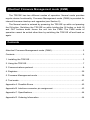
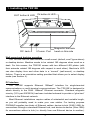
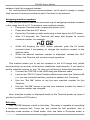
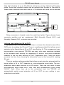
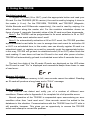
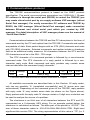
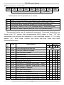
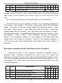
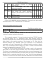
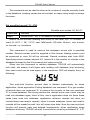
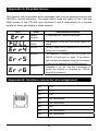
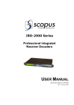
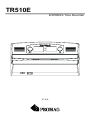
TR510E
EXPRESS Time Recorder
V1.5-0
Attention! Firmware Management mode (FMM)
The TR510E has two different modes of operation. Normal mode provides
regular device functionality. Firmware Management mode (FMM) is provided for
internal firmware checkup and upgrades (see Section 5).
The Normal mode is entered by powering the TR510E up while not pressing
the IN button. Switching the TR510E on while holding the IN button or both IN
and OUT buttons down forces the unit into the FMM. The FMM mode of
operation cannot be exited other than by switching the TR510E off and back on
again.
Contents
Attention! Firmware Management mode (FMM) .................................................. 2
Contents............................................................................................................... 2
1. Installing the TR510E....................................................................................... 3
2. Using the TR510E............................................................................................ 7
3. Communications protocol ................................................................................ 8
4. Registers ........................................................................................................ 25
5. Firmware Management mode ........................................................................ 38
6. Test mode ...................................................................................................... 41
Appendix A. Possible Errors .............................................................................. 43
Appendix B. Interface connector pin assignment............................................... 43
Appendix C. Specifications ................................................................................ 44
Appendix D. Ordering Information...................................................................... 44
1. Installing the TR510E
OUT button & LED
DC Jack
IN button & LED
Comm. Port
Magnetic/ barcode
head on this side
Wall-mount and desktop operation
The TR510E can be used either as a wall-mount (default, see Figure above)
or desktop device. Machine needs to be rotated 180 degrees when used on a
desk. For this reason, the TR510E comes with two different LED plates (with
their artworks rotated 180 degrees with respect to each other). Machine’s LED
can also display time and other data in a “normal” (wall-mount), or desktop
fashion. There is an orientation setting provided that allows you to select display
mode (see Section 4).
PC interface
The TR510E supports Ethernet 10BaseT interface for single-terminal
communications or multi-terminal communications. The TR510E is designed to
attach directly to the RJ45 10BaseT Ethernet connector. Standard magnetic
circuitry (YCL part 20F001N) has been included onboard to provide a “glue-less”
interface to the Ethernet network.
Most Ethernet installations require cables of substantial and variable length,
so you will probably need to make your own cables. For testing purpose
PROMAG supplies two kinds of Ethernet cables: device-to-hub (WAS-1499) for
connections through a standard Ethernet hub, and device-to-device (Was-1498)
for connections without a hub (i.e. directly from one Ethernet device to another).
3
TR510E User’s Manual
Ethernet arrangement is simple: just plug the Ethernet cable (use supplied or
your own cables) into the TR510E’s RJ45 connector and connect the other side
to the Ethernet port of HUB (see the drawing below).
TR510E’s interface connector pin assignment can be found in Appendix B.
Understanding machine numbers
For single-terminal Ethernet communications, you needn’t specify your
TR510E’s machine number let it be the default number (#00) is our suggestion.
For multi-terminal Ethernet communications and for your easy to identify, you
sure have all Terminals on the network have unique machines numbers, even
machine number is not a network address that uniquely identifies the Terminal
on the network. Each TR510E must be assigned a unique IP address. It is a
common convention to write the IP address in a so-called “dot notation”, i.e.
“192.168.100.215”. Consult with your Network Administrator to determine the
suitable IP address for each TR510E you are planning to install on the network.
Note, the matching IP address must also be set in the PC software you are
using to control the TR510E. For your easily setting the IP address and
others setting about network, we supply a set up software called DS
manager (Device Server manager). For detail please see the manual of
“Quick Start Guide”.
Having two different Terminals on the network set up to the same machine
number will result in the inability to communicate with both Terminals.
Machine number can be in the 0 to 255 range (00-FF Hex). 0 is a universal
machine number- any Terminal responds to it regardless of this Terminal’s
actual machine number setting. Machine number of 0 can be used for Ethernet
communications- you only have a single Terminal in this case, so you can
4
TR510E User’s Manual
address it with the universal number.
For multi-terminal Ethernet communications, you’ll need to assign a unique
(and non-zero!) machine number to each Terminal on the network.
Assigning machine numbers
The TR510E offers a fast and convenient way of assigning machine numbers
in the range from 0 to 10. To assign a new machine number:
•
Power the Terminal down (unplug the power cord)
•
Press and hold the OUT button
•
Power the Terminal up while continuing to hold down the OUT button
•
After 2-3 seconds, the Terminal will beep and display its current
machine number, for example:
•
While still keeping the OUT button pressed, push the IN button
(several times if necessary) to change the machine number to the
desired value
•
When the desired machine number is displayed, release the OUT
button- the Terminal will resume normal operation
This method allows you to set the numbers in the 0-10 range only (which
would actually cover most of the actual installation requirements). If you need to
set the machine number to, say, 25, then you will have to follow this procedure:
•
Connect the TR510E to the HUB using the Ethernet cable
•
Launch the TR510 Control Center software and select the Terminal #0
(i.e. use the universal machine number to address the Terminal)
•
Use the “Set M#” button to set the new machine number for this
Terminal
•
Use the “Get M#” button to get the new machine number for check if
machine number has changed.
Note: machine number is displayed briefly at the Terminal power-up (even if
you don’t push the OUT button).
Bell relay
The TR510E features a built-in bell relay. The relay is capable of controlling
a low-power external bell. There are two modes for bell schedule, one is
Everyday mode another is Week mode. Only one table in Everyday mode, a
5
TR510E User’s Manual
daily bell schedule of up to 32 different bell times can be defined in Everyday
mode. Seven bell schedule tables can be defined from Sunday to Saturday in
Week mode, and each table also has up to 32 different bell times can be defined.
N.C.
C
N.O.
Relay connector is located under the metal back plate. Figure above shows
connector position and pin assignment. Both Normally Closed (N.C.) and
Normally Opened (N.O.) contacts are provided.
Locking event selection (IN or OUT)
By default, the TR510E allows the User to choose the desired event (IN or
OUT) prior to reading the ID-card. There is a setting provided that allows event
selection to be fixed either at IN or OUT (see Section 4). This arrangement may
be desirable in case several TR510Es are used, with some machines installed
at the entrance and serving for registering IN events, and some machines
installed at the exit and serving for OUT registration only. Fixing the event
prevents the User from choosing an alternative event at the moment of reading
ID-card.
There is another setting provided that allows event selection automatically to
be set either at IN or OUT depends on a pre-scheduled event table. The prescheduled event table features up to 32 entries. There are two fields of each
pre-scheduled event table entry: ‘time’ field and corresponding event mode
‘IN/OUT’ field. When time up to the scheduled time, the TR510E will
automatically switch event selection at IN or OUT by your setting in prescheduled event table.
6
2. Using the TR510E
Clocking in and out
To register an event (IN or OUT), push the appropriate button and read your
ID-card. For the TR510ER (RFID version), the card is read by bringing it close to
the reader (< 8 cm). For the TR510EM, TR510EB, and TR510EF (Magnetic,
Visible Barcode and IR Barcode respectively), the card is read by swiping it in
either direction along the reader slot. For the machine orientation shown on
figure of page 3, magnetic (barcode) stripe of the ID-card must face downwards.
Note 1: the TR510E can be programmed to fix event selection to IN or OUT
only- in this case event selection won’t work!
Note 2: for automatically activation at IN or OUT event, the TR510E provides
a pre-scheduled event table for user to arrange time and event for activation IN
or OUT in a scheduled time; in this mode, user can directly register ID-card in a
scheduled event, or register an event by manually push the appropriate button;
in this way, TR510E will go back to scheduled event (IN or OUT) when finish the
card reading. If user does not has his ID-card to be read after press a button,
TR510E will automatically go back to scheduled event after 5 seconds time out.
The last four digits of the ID-cards ID-code are displayed on the LED when
the ID-card is read. “Err” is displayed and meanwhile beeps three times in case
of read error:
Memory full status
When the database memory is full, new records cannot be added. Reading
an ID-card will produce a long beep and a “FULL” message:
Error conditions
The TR510E can detect and notify you of a number of different error
conditions. Please refer to Appendix A for complete list of all possible errors.
Normal operation of the TR510E is suspended upon encountering an error
condition other than “card read error”. New records cannot be added to the
database in this situation. Communications with the TR510E from the PC side is
still possible, however. This gives you an opportunity to access the TR510E
online and attempt to correct the problem.
7
3. Communications protocol
The TR510E communications protocol is based on the GNET protocol
specification. The serial communications parameters are 19200-8-N-1. If your
PC software is through the serial port (RS232) to control the TR510E, you
may create virtual serial port by our supply software VSP manager (virtual
Serial Port manager). For easily connection PC software and TR510E by
RS232, the VSP manager (Virtual Serial Port manager) make connection
between Ethernet and virtual serial port which you created by VSP
manager. For detail description of VSP manager please see the manual of
“Quick Start Guide”.
Communications between the TR510E and the PC takes place in the form of
commands sent by the PC and replies from the TR510E. Commands and replies
are packets of data. Each packet begins with an STX (02H) character and ends
with CR (0DH) character. Selected commands and replies include a checksum
field as an additional safety measure. All characters between the STX and the
CR characters must be in the 20H...7FH range.
The STX character of a command packets is followed by a one-character
command code. The STX character of a reply packet is followed by a onecharacter reply code. Both command and reply packets may contain some
relevant data after the command (reply) character:
STX
Cmd/Rpl
02H
code
C1
Data (if any)
C2
CR
Checksum*
0DH
*Checksum field is not included into certain commands and replies
All available commands are described later in this Section. Of reply codes,
only two are possible: ‘A’ (completed successfully) and ‘N’ (some error was
encountered). Depending on the command given to the TR510E, reply packets
with reply code ‘A’ may contain some data (as shown on the Figure above).
Reply packets with the reply code ‘N’ always contain a 2-digit error code that can
be used to analyze the source of a problem.
The checksum is an 8-bit sum of all characters between the STX and CR,
represented as a 2-character HEX string. For an example packet below, the
checksum is calculated as follows. The data part of the packet is “A1XYZ”. The
sum of these character codes is: 41H+31H+58H+59H+5AH=17DH. Eight least
significant bits contain 7DH. The string representation of this value is “7D” (i.e. 2
8
TR510E User’s Manual
ASCII characters- ‘7’ and ‘D’).
STX
A
1
X
Y
Z
7
D
CR
02H
41H
31H
58H
59H
5AH
37H
44H
0DH
Packet portion the checksum is calculated on
Checksum
Table below lists all possible error codes:
04
Illegal (invalid) command (command code or data is wrong)
06
Record number is out of range (requested record doesn’t exist)
07
Command failed (hardware problem or invalid internal data)
08
Log (data) memory is full (this message reply in Extended mode)
09
Access has been denied (terminal is not in Extended mode)
Summarized below are all supported commands. Command characters are
found in the “CC” column, their corresponding ASCII codes- in “Hex”. “CS” lists
commands that require the checksum in the command packet (“C”) or reply
packet (“R”). “Error code” column lists errors that may result from each
command execution:
C.
Hex
Description
44H
Select designated terminal
Note 1
+
+
+
+
C.
‘D’
CS
Errors
C R 4
‘I’
49H
Set new machine number
‘Y’
59H
Get machine number
‘S’
53H
Set date/time
‘T’
54H
Get date/time
Get firmware version
6
7
+
+
‘V’
56H
‘R’
52H
Initialize the terminal
‘C’
43H
Set group-1 registers (see group-1 table)
‘B’
42H
Get group-1 registers (see group-1 table)
+
+
+
+
+
‘N’
4EH
Get number of records
+
‘G’
47H
Get specified record
+
+
‘E’
45H
Initialize the database
‘M’
4DH
Prepare for database recovery
‘P’
50H
Set group-2 registers (see group-2 table)
+
+
‘Q’
51H
Get group-2 registers (see group-2 table)
+
+
+
9
+
+
+
TR510E User’s Manual
‘J’
4AH
Set group-3 registers (see group-3 table)
‘K’
4BH
Get group-3 registers (see group-3 table)
‘Z’
5AH
Perform self-test**
+
+
+
+
+
Note 2
Note 1. D-command never returns error message even if the data supplied in the
command packet is incorrect. Invalid command packet makes it impossible to determine
which terminal is being addressed and, therefore, which one should reply with an error
code.
Note 2. Self-test takes place on the next power-up, not immediately.
The TR510E have 3 group registers. Group-1 is for accessing registers for
“LED mode”, “bell duration”, “32 entries of bell table times field (Everyday
mode)”, “32 entries of bell table enable/disable field (Everyday mode)”, “event
lock mode”, “Relay function”, “event table times field (32 entries)”, “event table
enable/disable field (32 entries)”, and “bell table mode (Everyday or Week)”,
“Daylight Saving Time”, “Enable/Disable Daylight Saving Time function”, “Door
lock duration”, “Prefix to match”, “From Character”, “Number of characters”.
Group-2 is for accessing registers of “7x32 entries for bell table times field
(Week mode, from Sunday to Saturday)”. Group-3 is for accessing registers of
“7x32 entries of bell table enable/disable field (Week mode, from Sunday to
Saturday)”.
Extended command-set (for Real-time access function):
Summarized below are all supported extended commands using in
extended mode. Command characters are found in the “CC” column (all
extended commands are lower case), their corresponding ASCII codes- in “Hex”.
“CS” lists commands that require the checksum in the command packet (“C”) or
reply packet (“R”). “Error code” column lists errors that may result from each
command execution:
C.
Hex
Description
C.
CS
Errors
C R 4
‘i’
69H
Log into Extended mode
‘o’
6FH
Log out from Extended mode
‘s’
73H
Get current login status
‘n’
6EH
Terminal sends captured-data to Host
10
+
7
9
TR510E User’s Manual
‘r’
72H
Host
requires
Terminal
to
resend
+
+
+
captured data
‘a’
61H
Host
acknowledges
that
data
has
+
received successfully
‘d’
64H
Host sends “4 digits” message to display
+
+
‘l’
6CH
Host
+
+
sends
the
“Relay
activation”
duration. (The command ‘l’ is lower case
of ‘L’)
‘p’
70H
Set punch times
‘u’
75H
Get punch times
+
+
+
Follows is the detailed command description. Command and reply packets
are shown without STX, Checksum and CR characters.
Select designated terminal (‘D’, 44H)
Possible error codes: none
Command
DNN
Reply
ANN,TR510E
NN is a machine (terminal) number in Hex form (00H-FFH), 00H is a
“universal” number (see below for details).
‘D’ is a special command. It is used to select a particular TR510E terminal.
All terminals power up in a “deselected” state. Each terminal ignores all
incoming commands until it receives the D-command whose machine number is
either equal to the machine number of this terminal, or 00. After that, the
terminal switches into “selected” state and responds to all subsequent
commands until new D-command with a different machine number is issued.
Thus, the D-command should always be used to initiate communications
between the host and the designated TR510E.
Note: the TR510E never returns any error codes in reply to this command.
This holds true for both “Illegal command” error and “Command failed” error.
The former is not responded to, because when there is some discrepancy in the
format of the D-command issued by the Host (which can only be in the Machine
Number field), no particular terminal can be “sure” that it is being addressed.
Therefore, no terminal on the network assumes responsibility for sending a reply.
11
TR510E User’s Manual
“Command failed” situation can only arise because of incorrect machine number
setting value in the TR510E memory. In this case, the terminal will be unable to
compare its internal machine number with the one supplied in the D-command.
Hence, the Terminal will not be able to make sure that it is being addressed.
Since 00 is a universal machine number, it works with any terminal. Use it
only when you have a single terminal connected to the network. Universal
machine number also comes handy during initial terminal setup (to assign a
unique machine number to the terminal prior to placing it on a multi-terminal
network).
The terminal replies with its actual machine number even if you address it
using 00. The only exception is when the terminal is unable to retrieve its own
machine number due to some internal malfunction. Reply will contain 00 instead
of an actual machine number in this case.
Set new machine number (‘I’, 49H)
Possible error codes: 04, 07
Command
INN
Reply
A
NN- machine number in Hex form (00H-FFH), 00 should never be used on a
multi-terminal network because this is a universal number (see D-command
description for details).
This command is used to assign a new machine number to the terminal.
Machine numbers provide a way to distinguish between the terminals on a multiterminal network. See D-command description for more details.
Get machine number (‘Y’, 59H)
Possible error codes: 07
Command
Y
Reply
ANN
NN- machine number in Hex form (00H-FFH)
This command is used to retrieve the terminal’s machine number. Machine
12
TR510E User’s Manual
numbers provide a way to distinguish between the terminals on a multi-terminal
network. See D-command description for more details.
Set date/time (‘S’, 53H)
Possible error codes: 04, 07
Command
SYYYYMMDDhhmmss
Reply
A
YYYY-year, MM- month, DD-date, hh-hour, mm-minutes, ss- seconds
This command is used to set the TR510E’s internal clock. Date/time
st
supplied must be valid. Incorrect data (like 31 of February) will be rejected
(error 04).
Get date/time (‘T’, 54H)
Possible error codes: 07
Command
T
Reply
AYYYYMMDDhhmmss
YYYY-year, MM- month, DD-date, hh-hour, mm-minutes, ss- seconds
This command is used to get the TR510E’s current date and time.
Get firmware version (‘V’, 56H)
Possible error codes: none
Command
V
Reply
Aversion_string
Version_string length is guaranteed to not exceed 61 character, all character
codes are guaranteed to be in the 20H…7FH range
This command can be used to verify the TR510E’s internal firmware version.
Although version string can be any ASCII string, the following format is adopted:
“VX.X cc…….c”, where “VX.X” is a version number (i.e. “V1.81”) and “cc…c”
13
TR510E User’s Manual
is a comment string. Comment string is separated from the version number by a
single space character. Version number will never have any spaces in it.
Initialize the terminal (‘R’, 52H)
Possible error codes: none
Command
R
Reply
A
This command is used to initialize the TR510E. Initialization takes place on
the next power-up, not immediately. Upon initialization, all setting values are
restored to their factory defaults. TR510E’s internal date and time are also
checked and, if contained garbage, initialized to 1999/01/01 and 00:00:00
respectively. The database data is not be erased, this must be done using the Ecommand.
Note: When first time turn power-up for TR510E after received ‘R’ command,
it will take 25 seconds to restore all factory defaults, in the meanwhile LED will
display “INIT”; please wait for this initialization procedure to complete:
Set group-1 register (‘C’, 43H)
Possible error codes: 04, 07
Command
CRR,reg_data
Reply
A
RR- register number (group 1) in Hex form (00H…FFH); reg_data- the data
for the register to be set
This command is used to set one of the TR510E “group-1 registers”.
Registers are actually functioning parameters (Settings). Complete description
of all available registers can be found in Section 4.
Get group-1 register (‘B’, 42H)
14
TR510E User’s Manual
Possible error codes: 04, 07
Command
BRR
Reply
Areg_datacc
RR- register number (group 1) in Hex form (00H…FFH), reg_data is the data
stored in the register, cc- checksum
This command is used to retrieve the data contained in the designated
“group-1 register”. Registers are actually functioning parameters (settings).
Complete description of all available registers can be found in Section 4.
Set group-2 registers (‘P’, 50H)
Possible error codes: 04, 07
Command
PRR,reg_data
Reply
A
RR- register number (group 2) in Hex form (00…FFH), reg_data is the data
for the register to be set
This command is used to set one of the TR510E “group-2 registers”.
Registers are actually functioning parameters (Settings) with respect to access
bell table ‘time’ field (7x32 entries) from Sunday to Saturday. Complete
description of all available registers can be found in Section 4.
Get group-2 registers (‘Q’, 51H)
Possible error codes: 04, 07
Command
QRR
Reply
Areg_datacc
RR- register number (group 2) in Hex form (00H…FFH), reg_data is the data
stored in the register, cc- checksum
This command is used to retrieve the data contained in the designated
“group-2 registers”. Registers are actually functioning parameters (settings) with
respect to access bell table ‘time’ field (7x32 entries) from Sunday to Saturday.
Complete description of all available registers can be found in Section 4.
15
TR510E User’s Manual
Set group-3 registers (‘J’, 4AH)
Possible error codes: 04, 07
Command
JRR,reg_data
Reply
A
RR- register number (group 3) in Hex form (00…FFH), reg_data is the data
for the register to be set
This command is used to set one of the TR510E “group-3 registers”.
Registers are actually functioning parameters (Settings) with respect to access
bell table ‘enable/disable’ field (7x32 entries) from Sunday to Saturday.
Complete description of all available registers can be found in Section 4.
Get group-3 registers (‘K’, 4BH)
Possible error codes: 04, 07
Command
KRR
Reply
Areg_datacc
RR- register number (group 3) in Hex form (00H…FFH), reg_data is the data
stored in the register, cc- checksum
This command is used to retrieve the data contained in the designated
“group-3 registers”. Registers are actually functioning parameters (settings) with
respect to access bell table ‘enable/disable’ field (7x32 entries) from Sunday to
Saturday. Complete description of all available registers can be found in Section
4.
Get number of records (‘N’, 4EH)
Possible error codes: 07
Command
N
Reply
ANNNNcc
NNNN- number of records in Hex form; cc- checksum
16
TR510E User’s Manual
This command can be used to retrieve the number of records currently found
in the database. Leading zeroes are not omitted, so reply string length is always
the same.
Get specified record (‘G’, 47H)
Possible error codes: 04, 06, 07
Command
GNNNN
Reply
ANNNN,ccc…c,E,YYYY/MM/DD,hh:mm:sscc
NNNN- record number (starting from 0000) in Hex form, ccc…c- ID-code, Eevent (0: OUT, 1: IN), YYYY- year, MM-month, DD-date, hh-hour, mm- minute,
ss- second, cc- checksum
This command is used to retrieve the database record with a specified
number. Record number must be supplied in Hex format, leading zeroes must
be preserved or error 04 will be returned. Record numbers start from 0000.
Specifying record number beyond N-1 (where N is the number of records in the
database returned by the N-command) will cause error 06.
When use this command to retrieve database, TR510E will automatically
lock itself, this means it will reject card reading until database stop retrieving,
then user’s card can be read again; in the meantime, LED will display ‘busy’ as
following:
This auto-lock function prevent data is deleted inadvertently for some
application. Some application Polling database use command ‘N’ to get number
of records then use command ‘G’ to retrieve the records, at last use command
‘E’ to erase database. But during retrieve the records some user card’s may be
read into database again, think of this, user’s application does not know these
cards have read into database, application retrieves records but does not
include these new read-in records, when it erases database, these new read-in
records will be erased as well, this will cause lose data. Now the new auto-lock
function will prevent data was deleted inadvertently; when application stops
database retrieving, TR510E will wait 3 seconds for receiving command ‘E’, if ‘E’
17
TR510E User’s Manual
command has received, TR510E erases database then unlock itself, user’s card
can be read again; or until 3 seconds Time-out TR510E still has not received ‘E’
command, however it will unlock itself but does not erase database.
Returned data string contains the record number, ID-code of the ID-card that
was used to create this record, event code (i.e. which button was pressed), and
the date and time of record creation.
The TR510E verifies all database records before sending them out to the PC.
This is done because the FLASH memory may actually contain a garbage data.
There is a special M-command that lets you initialize the database in such a way
that it appears to be 100% full (you can “recover” entire database memory
contents then). Naturally, some database records may turn out to contain invalid
data.
Database record validity is verified on a field-by-field basis. Should the field
turn out to be invalid, its contents are substituted for a “safe” default data:
•
ID-code. If ID-code turns out to contain illegal characters (i.e. with
codes outside of 20H-7FH range), then these characters are
substituted for “_”. If ID-code length is outside of valid margins* then
entire ID-code is substituted for the following code: “0000000000” (ten
‘0’ characters)
•
nd
Date. If the date is invalid (i.e. December, 32 ) then default date
(1999/01/01) is used
•
Time. If the time is invalid (i.e. 24:00:00) then default time is used
•
Event. if Event code exceeds 1, then this field is substituted for “0”.
*Note: for JIS-II code, the valid length of ID-code is “1<= margin <=69”; for
Track1 code, the valid length of ID-code is “1<= margin <=76”; for Track2 code,
the valid length of ID-code is “1<= margin <=37”.
Initialize the database (‘E’, 45H)
Possible error codes: none
Command
E
Reply
A
Executing this commands initializes the database. This command can be
18
TR510E User’s Manual
used to delete all database data and restore the database functionality in case
of database malfunction.
E-command doesn’t really delete the data itself- just some internal database
housekeeping is initialized. The data can still be (partially) recovered using an
M-command.
Prepare for database recovery (‘M’, 4DH)
Possible error codes: none
Command
M
Reply
A
This command alters the database in such a way that it appears to be 100%
full. The M-command, therefore, can be used for data recovery purposes. For
example, if E-command is executed accidentally while TR510E had some useful
data inside, then M-command can be used to download entire database memory
contents. Naturally, this recovered data may not be consistent. Some records
may contain “garbage” data (more on this in G-command description), newer
records may overlap older ones, etc.
Perform self-test (‘Z’, 5AH)
Possible error codes: none
Command
Z
Reply
This command is never replied to
This command is used to force the TR510E into a special Test mode. Selftest takes place on the next power-up, not immediately. Details of TR510E’s
operation in the Test mode are provided in Section 6. Note, that Test mode
destroys database memory contents in such a way that the data cannot be
recovered even with the M-command.
Note: When turn power-up at first time for TR510E after self-test, it will take
25 seconds to restore all factory defaults, please wait for this initialization
procedure; the LED will display “INIT” while initialization is in progress:
19
TR510E User’s Manual
Extended command-set description:
Log into Extended mode (‘i’, 69H)
Possible error codes: none
Command
i
Reply
A
This command logs the TR510E into Extended mode whatever TR510E is
currently in Extended mode or not. If you want to use other extended commands
TR510E should be logged into Extended mode first. In Extended mode, TR510E
can send the captured data to Host in Real-time.
Log out from Extended mode (‘o’, 6FH)
Possible error codes: none
Command
o
Reply
A
This command logs the TR510E out from Extended mode. When TR510E
has logged out from Extended mode, TR510E cannot use extended commands
anymore except commands ‘i’, ‘o’, and ‘s’.
Get login status (‘s’, 73H)
Possible error codes: none
Command
s
Reply
AMMcc
MM- login status (00: logged out extended-mode, 01: logged in extendedmode), cc-checksum
This command gets the current login status of TR510E. Use this command
to check if TR510E is in Extended mode or not before use other extended
20
TR510E User’s Manual
commands.
Terminal sends captured data to Host (‘n’, 6EH)
Possible error codes: none
Command
nNNNN,ccc…c,E,YYYY/MM/DD,hh:mm:sscc
Reply
A
NNNN- record number in Hex form, ccc…c- ID-code, E- event (0: OUT, 1:
IN), YYYY- year, MM-month, DD-date, hh-hour, mm- minute, ss- second, ccchecksum
This command is used to send the currently captured record to Host. The
returned record number is supplied in Hex format. The TR510E also stores this
captured record into its database memory.
Host should acknowledge that the captured record has received successfully
by command ‘a’ (61H), or requires TR510E to send the captured record again by
command ‘r’ (72H) when data receiving failure.
Returned data string contains the record number, ID-code of the ID-card that
was used to create this record, event code (i.e. which button was pressed), and
the date and time of record creation.
The TR510E verifies the currently captured record before sending it out to
the Host.
Captured record validity is verified on a field-by-field basis. Should the field
turn out to be invalid, its contents are substituted for a “safe” default data:
•
ID-code. If ID-code turns out to contain illegal characters (i.e. with
codes outside of 20H-7FH range), then these characters are
substituted for “_”. If ID-code length is outside of valid margins then
entire ID-code is substituted for the following code: “0000000000” (ten
‘0’ characters)
•
nd
Date. If the date is invalid (i.e. December, 32 ) then default date
(1999/01/01) is used
•
Time. If the time is invalid (i.e. 24:00:00) then default time is used
•
Event. If Event code exceeds 1, then this field is substituted for “0”.
Note: for JIS-II code, the valid length of ID-code is “1<= margin <=69”; for
Track1 code, the valid length of ID-code is “1<= margin <=76”; for Track2 code,
21
TR510E User’s Manual
the valid length of ID-code is “1<= margin <=37”.
Host require sending captured data again (‘r’, 72H)
Possible error codes: 07, 09
Command
r
Reply
nNNNN,ccc…c,E,YYYY/MM/DD,hh:mm:sscc
NNNN- record number in Hex form, ccc…c- ID-code, E- event (0: OUT, 1:
IN), YYYY- year, MM-month, DD-date, hh-hour, mm- minute, ss- second, ccchecksum
If data receiving is failure host can require TR510E to resend currently
captured record by this command. And then TR510E will resend the currently
captured record by ‘n’ (6EH) command again, see ‘n’ (6EH) command
description for details.
Host acknowledges data received successfully (‘a’, 61H)
Possible error codes: 09
Command
a
Reply
However, host must send this command to TR510E to acknowledge the data
has received successfully. After send captured data to host, TR510E will wait
host to send this command for 5 seconds, during this 5 seconds TR510E will
reject any card reading. Therefore, host shall acknowledge this command as
soon as possible.
Host sends “4 digits” message to display (‘d’, 64H)
Possible error codes: 04, 09
Command
dNNNNss
Reply
A
NNNN- 4 digits message (0000-9999) in string type, ss- message display
22
TR510E User’s Manual
duration in seconds (01-99), also string type.
This command is used to display 4 digits message on TR510E’s LED
display for a duration time. The message code and its meaning is defined by
user, only numeric can be defined, do not define alphabet. The code range is
from 0000 to 9999 in string type.
Host sends “relay activation” duration (‘l’, 6CH)
Possible error codes: 04, 07, 09
Command
lNN
Reply
A
NN- relay activation duration in 01-99 (string type) seconds, 00 should never
be used as duration.
This command ‘l’ (lower case ‘L’) is used to assign relay activation duration
in seconds. When relay is used to control Bell, send this command to TR510E
will get error code- “command failed”.
Set punch times (‘p’, 70H)
Possible error codes: 04, 07
Command
pNN
Reply
A
NN- punch times in Hex form (00H-0AH), 00: disable, 01-0A: legal value for
punch times.
For some unknown reason device may be disconnected from network, and
device will lose control by Host. For use device as stand alone work, user can
has his card to be read in several times then device will auto log-out from
Extended mode. The ‘p’ command sets punch times in range 01 to 10 (01-0A in
Hex format), and 00 will disable this auto switching to log-out mode function.
Get punch times (‘u’, 75H)
23
TR510E User’s Manual
Possible error codes: 07
Command
u
Reply
ANN
NN- punch times in Hex form (00H-0AH)
This command is used to retrieve the device’s punch times. Punch times
provide a way to use device as stand alone work when device was lost control
from network. User has his card to be read in this defined “punch times” then
device will be continue used in stand alone work (disconnection from network).
24
4. Registers
The TR510E feature 3 groups of programmable “registers”. Basically,
registers are the TR510E’s functioning parameters (Settings). Group-1 registers
can be written to using the C-command, and read from using the B-command;
Group-2 registers can be written to using the P-command, and read from using
the Q-command; Group-3 registers can be written to using the J-command, and
read from using the K-command (see Section 3 for details).
Table below lists all available group-1 registers:
00H
LED display mode (0: wall-mount, 1:desktop)
01H
Bell duration in seconds (00H-FFH)
02H-21H
Bell table, times (total of 32 registers)
22H-41H
Bell table, enable/disable (total of 32 registers)
42H
Event selection mode, free (IN or OUT), IN only, OUT only,
or Scheduled
43H
Relay function (0: for Alarm, 1: for Door unlock)
44H-63H
Event table, times (total of 32 registers)
64H-83H
Event table, event selection (IN:1, OUT:0)
84H
Bell table mode, Everyday or Week (Everyday:0, Week:1)
85H-86H
Daylight Saving Time (start-time ~ end-time)
87H
Enable or Disable Daylight Saving Time function
88H
Door unlock duration in seconds (00H-FFH)
89H
Prefix to match (0-16 characters)
8AH
From character (extract from a character position in the ID-
8BH
Number of characters (extract a portion of code from ID-
code, this setting is from 1 to 37)
card, this setting is from 1 to 37)
8CH
Allow or disallow record duplication (1:allow, 0:disallow)
Table below lists all available group-2 registers:
00H-1FH
Bell table of Sunday, ‘time’ field (32 registers)
20H-3FH
Bell table of Monday, ‘time’ field (32 registers)
40H-5FH
Bell table of Tuesday, ‘time’ field (32 registers)
25
TR510E User’s Manual
60H-7FH
Bell table of Wednesday, ‘time’ field (32 registers)
80H-9FH
Bell table of Thursday, ‘time’ field (32 registers)
A0H-BFH
Bell table of Friday, ‘time’ field (32 registers)
C0H-DFH
Bell table of Saturday, ‘time’ field (32 registers)
Table below lists all available group-3 registers:
00H-1FH
Bell table of Sunday, ‘enable/disable’ field (32 registers)
20H-3FH
Bell table of Monday, ‘enable/disable’ field (32 registers)
40H-5FH
Bell table of Tuesday, ‘enable/disable’ field (32 registers)
60H-7FH
Bell table of Wednesday, ‘enable/disable’ field (32 registers)
80H-9FH
Bell table of Thursday, ‘enable/disable’ field (32 registers)
A0H-BFH
Bell table of Friday, ‘enable/disable’ field (32 registers)
C0H-DFH
Bell table of Saturday, ‘enable/disable’ field (32 registers)
LED display mode (group-1 register 00H)
Set
Possible error codes: 04, 07
Command
C00,MM
Reply
A
Get
Possible error codes: 04, 07
Command
B00
Reply
AMMcc
MM- display mode (00: wall-mount operation, 01: desktop operation), ccchecksum
This register is used to set the LED display mode. Because TR510E can be
used both as a wall-mount and as a desktop device, the LED data must be
displayed in either orientation. Setting register to 00 (default) adjusts LED
picture for wall-mount operation. Setting the register to 01 rotates the image so
that it appears correctly when operating as a desktop device. Note: the mode
parameter must be supplied as a 2-digit number, i.e. “00” or “01”. Supplying just
one digit will generate error 04.
26
TR510E User’s Manual
Bell duration (group-1 register 01H)
Set
Possible error codes: 04, 07
Command
C01,DD
Reply
A
Get
Possible error codes: 04, 07
Command
B01
Reply
ADDcc
DD- Bell duration in seconds, in Hex format (00H-FFH), cc- checksum
The TR510E features a relay that can be used for external bell control. Bell
schedule can be programmed using bell table registers (02H-21H, 22H-41H).
This register specifies the number of seconds the bell will be activated for each
time it is enabled.
Note: the DD parameter must always be a 2-digit number (i.e. “3A”).
Supplying just one digit will generate error 04.
Bell table (Everyday mode), times (group-1 registers 02H-21H)
Set
Possible error codes:04, 07
Command
CRR,hhmm
Reply
A
Get
Possible error codes: 04, 07
Command
BRR
Reply
Ahhmmcc
RR- register number (group 1) in Hex form (02-21H), hh- hour, mm-minutes,
cc- checksum
The TR510E features a relay that can be used for external bell control.
There are two bell modes are set by group-1 register 84H: Everyday mode and
Week mode, Everyday mode has only one table setting for everyday use, Up to
32 different ring times can be specified in the table which the bell will be
activated. Each bell table entry consists of two fields: ‘time’ field (set through
27
TR510E User’s Manual
these 32 group-1 registers) and a corresponding ‘enable/disable’ field (set
through group-1 registers 22H-41H).
Bell table (Everyday mode), enable/disable (group-1 registers 22H-41H)
Set
Possible error codes:04, 07
Command
CRR,SS
Reply
A
Get
Possible error codes: 04, 07
Command
BRR
Reply
ASScc
RR- register number (group 1) in the Hex form (22H-41H), SS- state (00:
disabled, 01: enabled), cc- checksum
The TR510E features a relay that can be used for external bell control. In
Everyday mode only one bell table can be set for everyday use. Up to 32
different bell times can be specified for which the bell will be activated. Each bell
table entry consists of 2 fields: ‘time’ field (set through group-1 registers 02H21H) and a corresponding ‘enable/disable’ field (set through these group-1
registers).
Example: programming a bell table entry for 12:00:00
First, set the desired time; select a time register that you haven’t used yet
(i.e. 05H). Set the time using the following command: “C05,1200”. Next, enable
this time through a corresponding enable/disable register. The corresponding
enable/disable register for time register 05H is 25H (time registers start from
th
02H, enable/disable registers start from 22H, we use the 4 register of each
group). Enable command looks like this: “C25,01”.
Event selection mode (group-1 register 42H)
Set
Possible error codes: 04, 07
Command
C42,EE
Reply
A
28
TR510E User’s Manual
Get
Possible error codes: 04, 07
Command
B42
Reply
AEEcc
EE- event selection mode (00: free selection by the User, 01: fix to OUT, 02:
fix to IN, 03: scheduled selection), cc- checksum
This setting defines if the TR510E will allow the User to choose the event (IN
or OUT), or event selection will be fixed to IN only or OUT only. Fixing event
may be desirable in case several TR510Es are used, with some machines
installed at the entrance and serving for registering IN events, and some
machines installed at the exit and serving for OUT registration only. TR510E
features scheduled selection mode, which allow user to arrange event activation
in a scheduled time, event schedule table ‘time’ field set by group-1 registers
44H-63H, event schedule table ‘IN/OUT’ field set by group-1 registers 64H-83H.
Relay function (group-1 register 43H)
Set
Possible error codes: 04, 07
Command
C43,LL
Reply
A
Get
Possible error codes: 04, 07
Command
B43
Reply
ALLcc
LL- relay function (00: for Alarm, 01: for Door Lock), cc- checksum
The TR510E features a relay that can be used for external bell or door
activation control. And it also has corresponding duration setting for bell or door
activation individually. See register 01 for bell duration setting; register 88H for
door unlocking duration setting.
Event table, times (group-1 registers 44H-63H)
Set
Possible error codes:04, 07
29
TR510E User’s Manual
Command
CRR,hhmm
Reply
A
Get
Possible error codes: 04, 07
Command
BRR
Reply
Ahhmmcc
RR- register number (group 1) in Hex form (44H-63H), hh- hour, mmminutes, cc- checksum
The TR510E features an event schedule table. Up to 32 different scheduled
times can be specified for which the event selection will be activated. Each
event table entry consists of two fields: ‘time’ field (set through these 32 group-1
registers) and a corresponding event selection ‘IN/OUT’ field (set through group1 registers 64H-83H).
Event table, selection mode- IN/OUT (group-1 registers 64H-83H)
Set
Possible error codes:04, 07
Command
CRR,SS
Reply
A
Get
Possible error codes: 04, 07
Command
BRR
Reply
ASScc
RR- register number (group 1) in the Hex form (64H-83H), SS- state (00:
OUT, 01: IN), cc- checksum
The TR510E features an event selection table. Up to 32 different scheduled
times can be specified for which the event selection will be activated. Each
event table entry consists of 2 fields: ‘time’ field (set through group-1 registers
44H-63H) and a corresponding event selection ‘IN/OUT’ field (set through these
group-1 registers).
Bell table mode (group-1 register 84H)
30
TR510E User’s Manual
Set
Possible error codes: 04, 07
Command
CRR,MM
Reply
A
Get
Possible error codes: 04, 07
Command
BRR
Reply
AMMcc
RR- register number (group 1) in the Hex form 84H, MM- bell table mode (00:
everyday mode, 01: 01week mode), cc-checksum
This group-1 register is used to set the bell table mode. TR510E have two
bell table modes: Everyday mode and Week mode, Everyday mode has only
one bell table which have 32 different bell times can be specified for everyday to
activate the bell. Week mode have 7 tables express from Sunday to Saturday,
each table have 32 different bell times and can be specified for the day of week
to activate the bell.
Daylight saving time (group-1 registers 85H-86H)
Set
Possible error codes:04, 07
Command
CRR,MMDD
Reply
A
Get
Possible error codes: 04, 07
Command
BRR
Reply
AMMDDcc
RR- register number (group-1) in Hex form (85H-86H), MM- month, DD-date,
cc- checksum
The TR510E provides Daylight Saving Time function, the daylight saving
start-time (string type) is set by group-1 register 85H, and the daylight saving
end-time (string type) is set by group-1 register 86H. When time reaches 2:00:00
AM of the start-time, time will change from 2:00:00 AM to 3:00:00 AM. When
time reaches 2:00:00 AM of the end-time, time will change from 2:00:00 AM to
1:00:00 AM. After finishing the start-time and end-time setting, don’t forget to
enable Daylight Saving Time function by setting group-1 register 87H as 01,
31
TR510E User’s Manual
then the function will work immediately. If set the start-time same as end-time,
the Daylight Saving Time function will be automatically disabled by TR510E
itself but content of register 87H will not be changed. If set the date of start-time
behind end-time TR510E will consider the date of start-time as next year date.
Note: February 29 will be denied to set as start-time or end-time by TR510E.
Daylight Saving, enable/disable (group-1 register 87H)
Set
Possible error codes:04, 07
Command
C87,SS
Reply
A
Get
Possible error codes: 04, 07
Command
B87
Reply
ASScc
SS- state (00: disabled, 01: enabled), cc- checksum
The Daylight Savings Enable/Disable register is use to enable or disable
Daylight Saving Time function. The default factory setting is 00 (disabled).
Note: when start-time and end-time were set as same date, TR510E will
automatically disable Daylight Saving Time function.
Door unlock duration (group-1 register 88H)
Set
Possible error codes: 04, 07
Command
C88,DD
Reply
A
Get
Possible error codes: 04, 07
Command
B88
Reply
ADDcc
DD- Door unlock duration in seconds, in Hex format (00H-FFH), ccchecksum
The TR510E features a relay that can be used for external bell or door lock
32
TR510E User’s Manual
activation control. This register specifies the number of seconds for the Door
lock relay activation duration. Please see register 01 for the Bell relay activation
duration.
Prefix to match (group-1 register 89H)
Set
Possible error codes: 04, 07
Command
C89,prefix_string
Reply
A
Get
Possible error codes: 04, 07
Command
B89
Reply
Aprefix_stringcc
prefix_string is the string of prefix to be set (0-16 digits long), cc- checksum
Prefix to match allows you to restrict the User ID-cards accepted by the
TR510E to cards whose leading ID-code characters match those of the prefix
string. This way you can setup the system to accept only certain ID-Cards. You
can even implement a simple access control function (using the TR510E as an
Control Terminal).
The prefix can be from 0 to 16 digits long. Entering a string with 0(none)
character disables prefix checking- any readable User Card will be accepted. If
the Prefix String is set, the TR510E will compare each User Card with this String
and reject the Cards that do not match, for example:
If Prefix to match is set to “123” then the TR510E will accept Cards such as
“1234”, “123679”, “123”. The terminal will reject the Cards with codes like
“14377” and “12”.
Default value for this setting is “” (empty string), i.e. prefix matching is
disabled.
From Character (group-1 register 8AH)
Set
Possible error codes: 04, 07
Command
C8A,NN
Reply
A
33
TR510E User’s Manual
Get
Possible error codes: 04, 07
Command
B8A
Reply
ANNcc
NN- a character position in the ID-Code counting from 1 in Hex form (range:
01H-25H), cc- checksum
From Character, together with Number of characters setting allows you to
extract and store into the database a portion of code from the User UD-Card
instead of the entire ID-Card code. This way you can adjust the format of the
data generated by the TR510E to the requirements of some specific PC
software. You can also use this setting to “hide” a certain portion of the ID-Cards
code. This is useful for simple access control function implementation.
From Character defines a character position in the ID-Code (counting from
1), starting from which the portion of an ID-code will be extracted. The valid
range for this setting is from 1 to 37. The TR510E will reject any User Card with
the ID-code with the number of characters in it smaller than current From
Character value.
Example: Supposing that From Character=3 and Number of characters=2.
Then, ID-code “123456” will be truncated to “34”, ID-code “123” will become “3”,
and ID-code “12” will be rejected.
Default value for this setting is 1.
Number of Characters (group-1 register 8BH)
Set
Possible error codes: 04, 07
Command
C8B,NN
Reply
A
Get
Possible error codes: 04, 07
Command
B8B
Reply
ANNcc
NN- the length of the position of code that will be extracted (in Hex form,
range: 01H-25H), cc- checksum
Number of Characters, together with From Character setting allows you to
34
TR510E User’s Manual
extract and store into the database a portion of code from the User UD-Card
instead of the entire ID-Card code. This way you can adjust the format of the
data generated by the TR510E to the requirements of some specific PC
software. You can also use this Setting to “hide” a certain portion of the ID-Cards
code. This is useful for a simple access control function implementation.
Number of Characters defines the length of the portion of code that will be
extracted from the ID-code starting from the From Character position. The valid
value range for this setting is from 1 to 37. Actual number of extracted
characters can be smaller than that defined by the Number of Characters
Setting. This happens when (From Character + Number of characters – 1) >
length of ID-code. Examples:
If From Character=2 and Number of Characters=3 then ID-code “12345” will
produce “234”, and ID-code “123” will result in “23” only.
Default value for this Setting is 37.
Allow/disallow record duplication (group-1 register 8CH)
Set
Possible error codes: 04, 07
Command
C8C,MM
Reply
A
Get
Possible error codes: 04, 07
Command
B8C
Reply
AMMcc
MM- allow/disallow record duplication (00: disallow, 01: allow), cc-checksum
This group 1 register is used to set “allow” or “disallow” record duplication.
When set in “disallow” mode TR510 will check if ID-code and IN/OUT selection
is same as previous record in one minute, if same, the warning message is
indicated by a long beep and “DUPL” displayed by the LED:
Bell table (Week mode), times (group-2 registers 00H-DFH)
35
TR510E User’s Manual
Set
Possible error codes:04, 07
Command
PRR,hhmm
Reply
A
Get
Possible error codes: 04, 07
Command
QRR
Reply
Ahhmmcc
RR- register number (group 2) in Hex form (00-DFH), hh- hour, mm-minutes,
cc- checksum
The TR510E features a relay that can be used for external bell control. Up to
7x32 different bell times can be specified for one week to activate the bell.
These 7x32 bell times are programmed into 7 tables from Sunday to Saturday,
group-2 registers 00H-1FH program for Sunday table, group-2 registers 20H3FH program for Monday table, group-2 registers 40H-5FH program for Tuesday
table, group-2 registers 60H-7FH program for Wednesday table, group-2
registers 80H-9FH program for Thursday table, group-2 registers A0H-BFH
program for Friday table, and group-2 registers C0H-DFH program for Saturday
table. Each table has 32 bell table entries, each bell table entry consists of 2
fields: ‘time’ field (set through these group-2 registers 00H-DFH) and a
corresponding ‘enable/disable’ field (set through group-3 registers 00H-DFH).
Bell table (Week mode), enable/disable (group-3 registers 00H-DFH)
Set
Possible error codes:04, 07
Command
JRR,SS
Reply
A
Get
Possible error codes: 04, 07
Command
KRR
Reply
ASScc
RR- register number (group 3) in the Hex form (00H-DFH), SS- state (00:
disabled, 01: enabled), cc- checksum
36
TR510E User’s Manual
The TR510E features a relay that can be used for external bell control. Up to
7x32 different bell times can be specified for one week to activate the bell.
These 7x32 bell times are programmed into 7 tables from Sunday to Saturday,
group-3 registers 00H-1FH program for Sunday table, group-3 registers 20H3FH program for Monday table, group-3 registers 40H-5FH program for Tuesday
table, group-3 registers 60H-7FH program for Wednesday table, group-3
registers 80H-9FH program for Thursday table, group-3 registers A0H-BFH
program for Friday table, group-3 registers C0H-DFH program for Saturday table.
Each table has 32 bell table entries, each bell table entry consists of 2 fields:
‘time’ field (set through group-2 registers 00H-DFH) and a corresponding
‘enable/disable’ field (set through these group-3 registers 00H-DFH).
37
TR510E User’s Manual
5. Firmware Management mode
The TR510E also features new Firmware Management mode (FMM). FMM
allows you to quickly upgrade your TR510E’s internal firmware and also check
validity of the currently loaded firmware. Contact your dealer for the most recent
firmware upgrade files.
FMM itself has two sub-modes of operation: FMM/download mode and
FMM/check mode. FMM/download is entered by keeping the IN button pressed
while the TR510E is powering up. FMM/check mode is entered by holding both
IN and OUT buttons pressed while the TR510E is powering up.
Downloading new firmware (FMM/download)
To upgrade the firmware, you will need a new firmware file and a terminal
software for PC capable of transferring files using Xmodem protocol (Checksum
version).
All TR510E firmware files have a fixed size of exactly 64K (65536 bytes).
The list of popular and widely available terminal programs includes
HyperTerminal for Windows, QModem, and Term95. But please know that
these programs communicate with terminal equipment by serial port
(RS232), so you should create a virtual serial port at your PC site by using
our supply software VSP manager; Please see the detail by manual of
“Quick Start Guide”. Procedure below assumes the use of HyperTerminal
which is a part of a standard Windows-95/98/2000 distribution.
To upgrade the TR510E’s internal firmware:
•
Switch the TR510E off
•
Make sure that the TR510E which you want to update new firmware
and the HUB are interconnected with a network cable
•
Launch HyperTerminal and configure it as follows:
o
When Connection Description dialog opens, type any string (1
o
When Connect to dialog opens, select an appropriate COM port
character minimum) and press OK
from the Connect Using drop-down box (for example, “Direct to
COM3”)
o
When COMx Properties dialog appears, set communications
parameters as follows: Bits per second: 19200, Data bits: 8,
38
TR510E User’s Manual
Parity: None, Stop bits: 1, Flow control: None
o
•
The HyperTerminal’s main window will appear
Choose TransferÆSend file from the Main menu- the Send file
dialog will appear
•
In the Send file dialog, select the file you want to download and
•
The Xmodem file send for dialog will be displayed
•
Press and hold the IN button, then power up the TR510E while still
choose Xmodem protocol from the Protocol drop-down box
keeping the IN button pressed. The unit will generate a long beep and
display “FLLD” (FLASH Load):
•
When receiving the file, the TR510E will blink its IN LED (the LED is
on while the TR510E is receiving or expecting to receive a block of
data from the PC; the LED is off while the TR510E is programming the
data received into its internal FLASH memory)
•
Once the downloading is finished, the TR510E will execute one long
beep and display “DONE”:
•
You may start using the newly downloaded firmware after switching
the unit off and back on again.
Note: When turn power-up TR510E at first time after downloaded firmware
it will take 25 seconds to set default values for all internal registers, in the
meanwhile LED will display “INIT”:
A number of errors may occur during the download. Errors are displayed in
the ”ERRx” format, where x is the error number, for example:
In addition, the TR510E generates a beep pattern comprised of a long beep
followed by one or several short beeps. The number of beeps corresponds to
the error number.
All possible download-related error codes are listed in the table below:
39
TR510E User’s Manual
Err1
Communications error (invalid data received from the PC). The
most probable cause of this error is incorrect communications
parameters you’ve set in the HyperTerminal
Err2
The download file is too big (exceeds 64K). All TR510E firmware
files must be exactly 64K in size. Make sure you are trying to
downloading a correct one
Err3
FLASH memory failure. This normally indicates a serious internal
malfunction
The LED display is turned off after displaying the message for some time.
Finally, there is a timeout error that occurs when you start the download but
PC doesn’t send any data (or the TR510E cannot receive the data sent by the
PC). This happens when you either set communications parameters of the
HyperTerminal incorrectly or if you switch the TR510E on (with the IN button
pressed) before starting the XMODEM on the PC side (it should always be the
other way around: start XMODEM first, then switch the TR510E on).
The timeout error is indicated by a long beep and four dashes displayed by
the LED:
Checking existing firmware (FMM/check)
To check if the currently downloaded application firmware is valid:
•
Switch the TR510E off
•
Press and hold both IN and OUT buttons, then switch the TR510E
back on (while keeping both buttons pressed). The unit will generate a
long beep and display “FLCH” (FLASH check):
•
Memory checkup takes about 5 seconds to complete. OUT LED is on
while check is in progress. Upon test completion, the TR510E will
either display “DONE” in case the FLASH memory contains a valid
program, or “Err4” if internal program code is invalid.
40
6. Test mode
The TR510E provides a hardware Test mode that can be initiated by issuing
a Z-command (see Section 3).
Warning! Hardware test destroys the database contents (not just
deletes it logically), so the data cannot be recovered even using the Mcommand! The test mode also sets a so-called Reset flag: the TR510E will
be completely reinitialized on the next power-up after the test.
Once initiated, the Test mode cannot be exited other than by switching the
TR510E off.
The Test mode is comprised of two phases. Phase 1 performs automated
SRAM, RTC (real-time clock) and FLASH memory tests. Phase 2 consists of
manual button and reader tests.
Phase 1 begins immediately upon entering the Test mode. The LED displays
“TEST” at this time:
A number of errors can occur during this portion of the test: All errors are
displayed in the “ERRx” format, where x is the error number, for example:
All possible errors are listed in the table below:
Err1
SRAM test failure
Err2
RTC test failure
Err3
FLASH test failure
Upon successful completion of the automated tests, the TR510E will beep
and display “b1-5” (OUT LED will be switched on):
This means that the manual test phase has commenced. This phase
consists of three steps: OUT button test, IN button test, and reader test. Each
step must be repeated five times.
Press the OUT button and notice that “b1-5” changes to “b1-4”, “b1-3”, etc.
When you press the OUT button for the fifth time, the display will change to
“b2-5” and the IN LED will be switched on. Press the IN button five times to
41
TR510E User’s Manual
finish this test step.
The display reads “rd-5” at the beginning of the reader test. Read any IDcard five times to pass this portion of the test.
When all manual tests are finished, the TR510E will generate a long beep
and display “PASS”:
This indicates that the test sequence has been completed successfully. You
can still continue testing the buttons and the reader at this point. The TR510E
will behave as if in the Normal Mode of operation, but no records will be added
to the database.
42
Appendix A. Possible Errors
This Section lists all possible error messages that may be generated during the
TR510E’s normal operation. The table below does not apply to the Test and
FMM modes of the TR510E (see Sections 5 and 6 respectively for complete
details on errors generated in these modes).
LED
Error
Read
Description/ Remedy
ID-card read error. Read the card again
error
Database
The database is full and new record cannot be
full
added.
Error 4
Incorrect setting value. Reinitialize the TR510E by
Error 5
The database is corrupted. First, try to power the
issuing the R-command
TR510E off and back on again. If this doesn’t
help, initialize the database using the E-command
or recover the database using the M-command
Error 6
Time/date is not set. Use the S-command to
correct the problem or reinitialize the TR510E
using the R-command
Appendix B. Interface connector pin assignment
#1
TX+
#2
TX -
#3
RX+
#4
No connection
#5
No connection
#6
RX-
#7
No connection
#8
No connection
43
TR510E User’s Manual
Appendix C. Specifications
Display:
4 x 7-segment LED
Magnetic card reader:
ISO Track 2, 75 bpi
Barcode reader:
Visible or IR, numerical Code39
RFID card reader:
125KHz, ASK, 64bits, Manchester encoding
RFID reading range, ISO card-sized tag
8 cm
Database capacity
App. 8168 records / 4084 records**
Supported interfaces
10BaseT Ethernet (RJ45)
Communications parameters
19200-8-n-1*
Bell control relay
1A, 12V max
Physical dimensions
170(L) x 99(W) x 48(H) mm
Installation
Wall-mount or desktop
Power supply
DC 9V, 500mA
Operating temperature range
0-55 Co
Operating humidity
5-95%
* for Virtual Serial Port use (see detail by “Quick Start Guide”)
** If ID-code is Track 1 or JIS-II code, database capacity is 4084 records
Appendix D. Ordering Information
TR510EM
EXPRESS Time Recorder with Magnetic Card Reader
TR510ER
EXPRESS Time Recorder with RFID Card Reader
TR510EB
EXPRESS Time Recorder with Barcode Card Reader (visible)
TR510EF
EXPRESS Time Recorder with Barcode Card Reader (infrared)
44