1
ACUIX™
Analog PTZ High Speed Dome
User Guide
Document 800-05662V1 – Rev A – 04/11
Revisions
Rev
Date
Revisions
A
04/11
New document to replace 800-05662. Updated to include firmware V3.7 changes.
ACUIX™ PTZ High Speed Analog Dome Installation and Configuration Guide
Contents
1
Introduction . . . . . . . . . . . . . . . . . . . . . . . . . . . . . . . . . . . . . . . . . . . . . . . 1
About the ACUIX™ High-Speed PTZ Dome . . . . . . . . . . . . . . . . . . . . . . . . . . . . . . . . 1
Setup and Configuration . . . . . . . . . . . . . . . . . . . . . . . . . . . . . . . . . . . . . . . . . . 2
Additional Information . . . . . . . . . . . . . . . . . . . . . . . . . . . . . . . . . . . . . . . . . . . 2
2
Installing the Scan Assembly. . . . . . . . . . . . . . . . . . . . . . . . . . . . . . . . . . . . . . 3
Preparing to Install the Scan Assembly . . . . . . . . . . . . . . . . . . . . . . . . . . . . . . . . . . 3
Installing the Scan Assembly. . . . . . . . . . . . . . . . . . . . . . . . . . . . . . . . . . . . . . . . 8
Installing the Bubble . . . . . . . . . . . . . . . . . . . . . . . . . . . . . . . . . . . . . . . . . . . . 9
3
Preparing to Configure the Dome . . . . . . . . . . . . . . . . . . . . . . . . . . . . . . . . . . 11
Pre-Configuration Checklist . .
Accessing the Main Menu . . .
Navigating OSD Menus . . . .
Sending the Dome to a Preset .
Special Presets . . . . . . . . .
OSD Menu Tree . . . . . . . .
4
.
.
.
.
.
.
.
.
.
.
.
.
.
.
.
.
.
.
.
.
.
.
.
.
.
.
.
.
.
.
.
.
.
.
.
.
.
.
.
.
.
.
.
.
.
.
.
.
.
.
.
.
.
.
.
.
.
.
.
.
.
.
.
.
.
.
.
.
.
.
.
.
.
.
.
.
.
.
.
.
.
.
.
.
.
.
.
.
.
.
.
.
.
.
.
.
.
.
.
.
.
.
.
.
.
.
.
.
.
.
.
.
.
.
.
.
.
.
.
.
.
.
.
.
.
.
.
.
.
.
.
.
.
.
.
.
.
.
.
.
.
.
.
.
.
.
.
.
.
.
.
.
.
.
.
.
.
.
.
.
.
.
.
.
.
.
.
.
.
.
.
.
.
.
.
.
.
.
.
.
.
.
.
.
.
.
.
.
.
.
.
.
.
.
.
.
.
.
.
.
.
.
.
.
.
.
.
.
.
.
.
.
.
.
.
.
. 11
. 12
. 13
. 13
. 14
. 15
Configuring the OSD . . . . . . . . . . . . . . . . . . . . . . . . . . . . . . . . . . . . . . . . . 17
Changing the OSD Language . . . . . . . . . .
Displaying the Dome Address . . . . . . . . . .
Displaying Sectors and Presets . . . . . . . . .
Displaying the Zoom Magnification . . . . . . .
Displaying the Startup Screen . . . . . . . . . .
Displaying Crosshairs . . . . . . . . . . . . . .
Displaying Dome Names . . . . . . . . . . . . .
Displaying the Pan, Tilt, and Zoom Coordinates.
Displaying the Time and Date . . . . . . . . . .
5
.
.
.
.
.
.
.
.
.
.
.
.
.
.
.
.
.
.
.
.
.
.
.
.
.
.
.
.
.
.
.
.
.
.
.
.
.
.
.
.
.
.
.
.
.
.
.
.
.
.
.
.
.
.
.
.
.
.
.
.
.
.
.
.
.
.
.
.
.
.
.
.
.
.
.
.
.
.
.
.
.
.
.
.
.
.
.
.
.
.
.
.
.
.
.
.
.
.
.
.
.
.
.
.
.
.
.
.
.
.
.
.
.
.
.
.
.
.
.
.
.
.
.
.
.
.
.
.
.
.
.
.
.
.
.
.
.
.
.
.
.
.
.
.
.
.
.
.
.
.
.
.
.
.
.
.
.
.
.
.
.
.
.
.
.
.
.
.
.
.
.
.
.
.
.
.
.
.
.
.
.
.
.
.
.
.
.
.
.
.
.
.
.
.
.
.
.
.
.
.
.
.
.
.
.
.
.
.
.
.
.
.
.
.
.
.
.
.
.
.
.
.
.
.
.
.
.
.
.
.
.
.
.
.
.
.
.
.
.
.
.
.
.
.
.
.
.
.
.
.
.
.
.
.
.
.
.
.
. 17
. 18
. 18
. 19
. 19
. 19
. 20
. 20
. 21
Configuring PTZ Control . . . . . . . . . . . . . . . . . . . . . . . . . . . . . . . . . . . . . . . 23
Setting PASS . . . . . . . . . . .
Setting Auto Pivot. . . . . . . . .
Setting the Pan and Tilt Speed . .
Setting Pan Reverse . . . . . . .
Setting Tilt Reverse . . . . . . . .
Setting the Tilt Limit. . . . . . . .
Finding Home on Startup . . . .
Setting the Pan Offset . . . . . .
Setting the Startup State Restore
Setting Auto Focus . . . . . . . .
Setting Timed Auto Focus . . . .
Document 800-05662V1 Rev A
04/11
.
.
.
.
.
.
.
.
.
.
.
.
.
.
.
.
.
.
.
.
.
.
.
.
.
.
.
.
.
.
.
.
.
.
.
.
.
.
.
.
.
.
.
.
.
.
.
.
.
.
.
.
.
.
.
.
.
.
.
.
.
.
.
.
.
.
.
.
.
.
.
.
.
.
.
.
.
.
.
.
.
.
.
.
.
.
.
.
.
.
.
.
.
.
.
.
.
.
.
.
.
.
.
.
.
.
.
.
.
.
.
.
.
.
.
.
.
.
.
.
.
.
.
.
.
.
.
.
.
.
.
.
.
.
.
.
.
.
.
.
.
.
.
.
.
.
.
.
.
.
.
.
.
.
.
.
.
.
.
.
.
.
.
.
.
.
.
.
.
.
.
.
.
.
.
.
.
.
.
.
.
.
.
.
.
.
.
.
.
.
.
.
.
.
.
.
.
.
.
.
.
.
.
.
.
.
.
.
.
.
.
.
.
.
.
.
.
.
.
.
.
.
.
.
.
.
.
.
.
.
.
.
.
.
.
.
.
.
.
.
.
.
.
.
.
.
.
.
.
.
.
.
.
.
.
.
.
.
.
.
.
.
.
.
.
.
.
.
.
.
.
.
.
.
.
.
.
.
.
.
.
.
.
.
.
.
.
.
.
.
.
.
.
.
.
.
.
.
.
.
.
.
.
.
.
.
.
.
.
.
.
.
.
.
.
.
.
.
.
.
.
.
.
.
.
.
.
.
.
.
.
.
.
.
.
.
.
.
.
.
.
.
.
.
.
.
.
.
.
.
.
.
.
.
.
.
.
.
.
.
.
.
.
.
.
.
.
.
.
.
.
.
.
.
.
.
.
.
.
.
.
.
.
.
.
.
.
.
.
.
.
.
.
.
.
.
. 23
. 24
. 24
. 24
. 25
. 25
. 25
. 26
. 27
. 27
. 28
iii
6
Configuring HDXA, HDXJ, and HDXF Camera Settings . . . . . . . . . . . . . . . . . . . . . . . 29
Setting the Zoom . . . . . . . . . . . . . . . . . . .
Setting Exposure . . . . . . . . . . . . . . . . . . .
Setting NightShot (True Day/Night) . . . . . . . . .
Setting White Balance . . . . . . . . . . . . . . . .
Setting E-Flip and Mirror Image . . . . . . . . . . .
Setting the Vertical Phase Edge . . . . . . . . . . .
Setting Wide Dynamic Range . . . . . . . . . . . .
Setting Motion Detection . . . . . . . . . . . . . . .
Setting the Video Gain and Lift (UTP Video Output) .
7
.
.
.
.
.
.
.
.
.
.
.
.
.
.
.
.
.
.
.
.
.
.
.
.
.
.
.
.
.
.
.
.
.
.
.
.
.
.
.
.
.
.
.
.
.
.
.
.
.
.
.
.
.
.
.
.
.
.
.
.
.
.
.
.
.
.
.
.
.
.
.
.
.
.
.
.
.
.
.
.
.
.
.
.
.
.
.
.
.
.
.
.
.
.
.
.
.
.
.
.
.
.
.
.
.
.
.
.
.
.
.
.
.
.
.
.
.
.
.
.
.
.
.
.
.
.
.
.
.
.
.
.
.
.
.
.
.
.
.
.
.
.
.
.
.
.
.
.
.
.
.
.
.
.
.
.
.
.
.
.
.
.
.
.
.
.
.
.
.
.
.
.
.
.
.
.
.
.
.
.
.
.
.
.
.
.
.
.
.
.
.
.
.
.
.
.
.
.
.
.
.
.
.
.
.
.
.
.
.
.
.
.
.
.
.
.
.
. 29
. 31
. 32
. 34
. 35
. 36
. 36
. 37
. 38
.
.
.
.
.
.
.
.
.
.
.
.
.
.
.
.
.
.
.
.
.
.
.
.
.
.
.
.
.
.
.
.
.
.
.
.
.
.
.
.
.
.
.
.
.
.
.
.
.
.
.
.
.
.
.
.
.
.
.
.
.
.
.
.
.
.
.
.
.
.
.
.
.
.
.
.
.
.
.
.
.
.
.
.
.
.
.
.
.
.
.
.
.
.
.
.
.
.
.
.
.
.
.
.
.
.
.
.
.
.
.
.
.
.
.
.
.
.
.
.
.
.
.
.
.
.
.
.
.
.
.
.
.
.
.
.
.
.
.
.
.
.
.
.
.
.
.
.
.
.
.
.
.
.
.
.
.
.
.
.
.
.
.
.
.
.
.
.
.
.
.
.
.
.
.
.
.
.
.
.
.
.
.
.
.
.
.
.
.
.
.
.
.
.
.
.
.
.
.
.
.
.
.
.
.
.
.
.
.
.
.
.
.
.
.
.
.
.
.
.
.
.
.
.
.
.
.
.
.
.
.
.
.
.
.
.
.
.
.
.
.
.
.
.
.
.
.
.
.
.
.
.
.
.
.
.
.
.
.
.
.
.
.
.
.
.
.
.
.
.
.
.
.
.
.
.
.
.
.
.
.
.
.
.
.
.
.
.
.
.
.
.
.
.
.
.
.
.
.
.
.
.
.
.
.
.
.
.
.
.
.
.
.
.
.
.
.
.
.
.
.
.
.
.
.
.
.
.
.
.
.
.
.
.
.
.
.
.
.
.
.
.
.
.
.
.
.
.
.
.
.
.
.
.
.
.
.
.
.
.
.
.
.
.
.
.
.
.
.
.
.
.
.
.
.
.
.
.
.
.
.
.
.
.
.
.
.
.
.
.
.
.
.
.
.
.
.
.
.
.
.
.
.
.
.
.
.
.
.
.
.
.
.
.
.
.
.
.
.
.
.
.
.
.
.
.
.
.
.
.
.
.
.
.
.
.
.
.
.
.
.
.
. 40
. 41
. 43
. 43
. 44
. 44
. 45
. 45
. 45
. 46
. 46
. 46
. 47
. 47
. 48
. 48
. 49
.
.
.
.
.
.
.
.
.
.
.
.
.
.
.
.
.
.
.
.
.
.
.
.
.
.
.
.
.
.
.
.
.
.
.
.
.
.
.
.
.
.
.
.
.
.
.
.
.
.
.
.
.
.
.
.
.
.
.
.
.
.
.
.
.
.
.
.
.
.
.
.
.
.
.
.
.
.
.
.
.
.
.
.
.
.
.
.
.
.
.
.
.
.
.
.
.
.
.
.
.
.
.
.
.
.
.
.
.
.
.
.
.
.
.
.
.
.
.
.
.
.
.
.
.
.
.
.
.
.
.
.
.
.
.
. 51
. 52
. 52
. 53
. 53
Configuring Presets, Tours, Privacy Zones, and Sectors . . . . . . . . . . . . . . . . . . . . . . 55
Configuring Presets . . . . . . . . . . . . . . . .
Configuring Advanced Presets . . . . . . . . . . .
Configuring Preset Tours . . . . . . . . . . . . . .
Configuring Mimic Tours . . . . . . . . . . . . . .
Configuring Default Functions: Presets and Tours
Configuring Timed Functions . . . . . . . . . . .
Configuring Privacy Zones . . . . . . . . . . . . .
Configuring Sectors . . . . . . . . . . . . . . . .
10
.
.
.
.
.
.
.
.
.
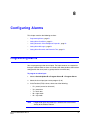
Configuring Alarms . . . . . . . . . . . . . . . . . . . . . . . . . . . . . . . . . . . . . . . . . . 51
Programming Alarms . . . . . . . . . . . . . .
Setting Alarm Conditions . . . . . . . . . . . .
Setting Automatic Acknowledgment Properties
Setting Alarm Messages . . . . . . . . . . . .
Setting Alarm Overwrite and Overwrite Time .
9
.
.
.
.
.
.
.
.
.
Configuring HDXG Camera Settings . . . . . . . . . . . . . . . . . . . . . . . . . . . . . . . . . 39
Setting the Zoom . . . . . . . . . . . . . . . . . . .
Setting Exposure . . . . . . . . . . . . . . . . . . .
Setting the Picture Brightness . . . . . . . . . . . .
Setting the Maximum AGC Level . . . . . . . . . . .
Setting the Chroma Level . . . . . . . . . . . . . .
Setting Backlight Compensation . . . . . . . . . . .
Setting Auto Slow Shutter . . . . . . . . . . . . . .
Setting Wide Dynamic Range . . . . . . . . . . . .
Setting Advanced Wide Dynamic Range. . . . . . .
Setting High Sensitivity Mode . . . . . . . . . . . .
Setting Field Noise Reduction . . . . . . . . . . . .
Setting White Balance . . . . . . . . . . . . . . . .
Setting E-Flip and Mirror Image . . . . . . . . . . .
Setting the Vertical Phase Edge . . . . . . . . . . .
Setting Image Stabilization . . . . . . . . . . . . . .
Setting Motion Detection . . . . . . . . . . . . . . .
Setting the Video Gain and Lift (UTP Video Output) .
8
.
.
.
.
.
.
.
.
.
.
.
.
.
.
.
.
.
.
.
.
.
.
.
.
.
.
.
.
.
.
.
.
.
.
.
.
.
.
.
.
.
.
.
.
.
.
.
.
.
.
.
.
.
.
.
.
.
.
.
.
.
.
.
.
.
.
.
.
.
.
.
.
.
.
.
.
.
.
.
.
.
.
.
.
.
.
.
.
.
.
.
.
.
.
.
.
.
.
.
.
.
.
.
.
.
.
.
.
.
.
.
.
.
.
.
.
.
.
.
.
.
.
.
.
.
.
.
.
.
.
.
.
.
.
.
.
.
.
.
.
.
.
.
.
.
.
.
.
.
.
.
.
.
.
.
.
.
.
.
.
.
.
.
.
.
.
.
.
.
.
.
.
.
.
.
.
.
.
.
.
.
.
.
.
.
.
.
.
.
.
.
.
.
.
.
.
.
.
.
.
.
.
.
.
.
.
.
.
.
.
.
.
.
.
.
.
.
.
.
.
.
.
.
.
.
. 55
. 57
. 59
. 62
. 65
. 66
. 67
. 70
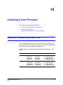
Installing Dome Firmware. . . . . . . . . . . . . . . . . . . . . . . . . . . . . . . . . . . . . . . 73
About the Firmware Downloader Tool . . . . . . . . . . . . . . . . . . . . . . . . . . . . . . . . . . . 73
Before You Begin . . . . . . . . . . . . . . . . . . . . . . . . . . . . . . . . . . . . . . . . . . . . . . 74
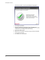
Updating Firmware Using the Downloader . . . . . . . . . . . . . . . . . . . . . . . . . . . . . . . . 74
iv
ACUIX™ PTZ High Speed Analog Dome Installation and Configuration Guide
11
System Administration and Equipment Handling . . . . . . . . . . . . . . . . . . . . . . . . . . 81
Configuring PINs and Passwords . . . . . . . . . . . . . . . . . . . .
Resetting the Dome . . . . . . . . . . . . . . . . . . . . . . . . . . .
Restoring the Default Settings . . . . . . . . . . . . . . . . . . . . . .
Changing the Dome Address, Protocol, Parity, and Baud Rate Settings
Sending Commands to All Domes . . . . . . . . . . . . . . . . . . . .
Maintaining the Dome . . . . . . . . . . . . . . . . . . . . . . . . . .
Appendix A
.
.
.
.
.
.
.
.
.
.
.
.
.
.
.
.
.
.
.
.
.
.
.
.
.
.
.
.
.
.
.
.
.
.
.
.
.
.
.
.
.
.
.
.
.
.
.
.
.
.
.
.
.
.
.
.
.
.
.
.
.
.
.
.
.
.
.
.
.
.
.
.
.
.
.
.
.
.
.
.
.
.
.
.
.
.
.
.
.
.
.
.
.
.
.
.
. 81
. 82
. 83
. 83
. 84
. 85
ACUIX Specifications . . . . . . . . . . . . . . . . . . . . . . . . . . . . . . . . . . 87
Factory Default Settings . . . . . . . . . . . . . . . . . . . . . . . . . . . . . . . . . . . . . . . . . . 87
Camera Specifications . . . . . . . . . . . . . . . . . . . . . . . . . . . . . . . . . . . . . . . . . . . 89
Appendix B
Troubleshooting . . . . . . . . . . . . . . . . . . . . . . . . . . . . . . . . . . . . . 91
General Troubleshooting . . . . . . . . . . . . . . . . . . . . . . . . . . . . . . . . . . . . . . . . . . 91
Troubleshooting Using Diagnostic Options . . . . . . . . . . . . . . . . . . . . . . . . . . . . . . . . 94
Appendix C
Understanding Automatic Exposure and NightShot . . . . . . . . . . . . . . . . . . 97
About the Lens Iris or Aperture and the F-Number . . . . .
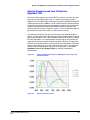
About Video Gain, Shutter Speed, and Spectral Response .
About ACUIX PTZ Dome Manual Exposure Control . . . . .
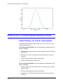
Operating NightShot (TDN) on ACUIX PTZ Camera Blocks .
Document 800-05662V1 Rev A
04/11
.
.
.
.
.
.
.
.
.
.
.
.
.
.
.
.
.
.
.
.
.
.
.
.
.
.
.
.
.
.
.
.
.
.
.
.
.
.
.
.
.
.
.
.
.
.
.
.
.
.
.
.
.
.
.
.
.
.
.
.
.
.
.
.
.
.
.
.
.
.
.
.
.
.
.
.
.
.
.
.
.
.
.
.
.
.
.
.
. 97
. 98
100
101
v
vi
ACUIX™ PTZ High Speed Analog Dome Installation and Configuration Guide
Figures
Figure 2-1
DIP Switch Locations . . . . . . . . . . . . . . . . . . . . . . . . . . . . . . . . . . . . . . 4
Figure 2-2
Switches SW1 to SW4 . . . . . . . . . . . . . . . . . . . . . . . . . . . . . . . . . . . . . . 5
Figure 2-3
ACUIX Scan Assembly. . . . . . . . . . . . . . . . . . . . . . . . . . . . . . . . . . . . . . 8
Figure 2-4
In-Ceiling Housing Bubble Installation . . . . . . . . . . . . . . . . . . . . . . . . . . . . . 9
Figure 2-5
Pendant Housing Bubble Installation . . . . . . . . . . . . . . . . . . . . . . . . . . . . . 10
Figure 2-6
Rugged Housing Bubble Installation . . . . . . . . . . . . . . . . . . . . . . . . . . . . . 10
Figure 3-1
OSD Main Menu . . . . . . . . . . . . . . . . . . . . . . . . . . . . . . . . . . . . . . . . 12
Figure C-1
Video Gain Equation . . . . . . . . . . . . . . . . . . . . . . . . . . . . . . . . . . . . . . 98
Figure C-2
Typical CCD Spectral Response with Magenta, Green, Cyan and Yellow Pixel Filters. . . . 99
Figure C-3
CIE 1931 Luminosity Curve . . . . . . . . . . . . . . . . . . . . . . . . . . . . . . . . . . 99
Figure C-4
ACUIX OSD NightShot Control Options Menu . . . . . . . . . . . . . . . . . . . . . . . 102
Figure C-5
NightShot Operation with ACUIX 18× and 26× TDN Camera Blocks . . . . . . . . . . . 104
Figure C-6
AE Control Menu and Example Settings . . . . . . . . . . . . . . . . . . . . . . . . . . 105
Figure C-7
35× TDN Camera with No Auto IR Cut Filter Operation . . . . . . . . . . . . . . . . . . 106
Figure C-8
35× TDN Camera with Auto IR Cut Filter Operation . . . . . . . . . . . . . . . . . . . . 106
Document 800-05662V1 Rev A
04/11
vii
viii
ACUIX™ PTZ High Speed Analog Dome Installation and Configuration Guide
Tables
Table 2-1
Default DIP Switch Settings. . . . . . . . . . . . . . . . . . . . . . . . . . . . . . . . . . . . 4
Table 2-2
Address Switch Assignments. . . . . . . . . . . . . . . . . . . . . . . . . . . . . . . . . . . 5
Table 2-3
SW5 Protocol Settings . . . . . . . . . . . . . . . . . . . . . . . . . . . . . . . . . . . . . . 6
Table 2-4
Baud Rate and Parity Settings by Protocol. . . . . . . . . . . . . . . . . . . . . . . . . . . . 7
Table 2-5
SW6 Baud Rate and Parity Settings . . . . . . . . . . . . . . . . . . . . . . . . . . . . . . . 7
Table 3-1
Special Presets . . . . . . . . . . . . . . . . . . . . . . . . . . . . . . . . . . . . . . . . . 14
Table 3-2
Menu Tree - 18× Color (HDXA), 18× WDR/TDN (HDXJ), 26× WDR/TDN (HDXF) . . . . . . 15
Table 3-3
Menu Tree - 35× WDR/TDN (HDXG) . . . . . . . . . . . . . . . . . . . . . . . . . . . . . . 16
Table 6-1
Minimum Focus Distances by Camera . . . . . . . . . . . . . . . . . . . . . . . . . . . . . 30
Table 6-2
Recommended Lift and Gain Settings by Cable Length . . . . . . . . . . . . . . . . . . . . 38
Table 7-1
Auto Exposure Control Mode Settings . . . . . . . . . . . . . . . . . . . . . . . . . . . . . 41
Table 7-2
Recommended Lift and Gain Settings by Cable Length . . . . . . . . . . . . . . . . . . . . 50
Table C-1
TDN Video Gain and Shutter Time Values . . . . . . . . . . . . . . . . . . . . . . . . . . 103
Table C-2
Auto Exposure Control Mode Settings . . . . . . . . . . . . . . . . . . . . . . . . . . . . 105
Document 800-05662V1 Rev A
04/11
ix
x
Important Safety Information
Before installing or operating the unit, read and follow all
instructions. After installation, retain the safety and operating
instructions for future reference.
1.
HEED WARNINGS - Adhere to all warnings on the unit and in the operating
instructions.
2.
INSTALLATION
•
•
•
•
Install in accordance with the manufacturer’s instructions.
Installation and servicing should be performed only by qualified and
experienced technicians to conform to all local codes and to maintain your
warranty.
Do not install the unit in an extremely hot or humid location, or in a place
subject to dust or mechanical vibration. The unit is not designed to be
waterproof. Exposure to rain or water may damage the unit.
Any wall or ceiling mounting of the product should follow the manufacturer’s
instructions and use a mounting kit approved or recommended by the
manufacturer.
3.
POWER SOURCES - This product should be operated only from the type of power
source indicated on the marking label. If you are not sure of the type of power
supplied to your facility, consult your product dealer or local power company.
4.
HEAT - Situate away from items that produce heat or are heat sources such as
radiators, heat registers, stoves, or other products (including amplifiers).
5.
WATER AND MOISTURE - Do not use this unit near water or in an unprotected
outdoor installation, or any area classified as a wet location.
6.
MOUNTING SYSTEM - Use only with a mounting system recommended by the
manufacturer, or sold with the product.
7.
ATTACHMENTS - Do not use attachments not recommended by the product
manufacturer as they may result in the risk of fire, electric shock, or injury to
persons.
8.
ACCESSORIES - Only use accessories specified by the manufacturer.
9.
CLEANING - Do not use liquid cleaners or aerosol cleaners. Use a damp cloth for
cleaning.
10. SERVICING - Do not attempt to service this unit yourself as opening or removing
covers may expose you to dangerous voltage or other hazards. Refer all servicing to
qualified service personnel.
11. REPLACEMENT PARTS - When replacement parts are required, be sure the
service technician has used replacement parts specified by the manufacturer or
have the same characteristics as the original part. Unauthorized substitutions may
result in fire, electric shock or other hazards. Using replacement parts or
accessories other than the original manufacturers may invalidate the warranty.
Document 800-05662V1 Rev A
04/11
xi
Warnings and Cautions
RISK OF ELECTRIC SHOCK
DO NOT OPEN
CAUTION: TO REDUCE THE RISK OF ELECTRIC SHOCK,
DO NOT REMOVE COVER (OR BACK).
NO USER SERVICEABLE PARTS INSIDE.
REFER SERVICING TO QUALIFIED SERVICE PERSONNEL.
CAUTION To prevent damage to the static-sensitive receiver and
power supply circuit boards, leave the scan assembly inside the
antistatic bag it was shipped in until the time of installation.
CAUTION To prevent damage to the interface and scan
assembly circuit boards, follow standard industry precautions for
electrostatic discharge sensitive devices.
xii
ACUIX™ PTZ High Speed Analog Dome Installation and Configuration Guide
Regulatory Statements
All ACUIX PTZs meet, as a minimum, Class A emissions standards. For the latest product
information, including information on ACUIX configuration certifications beyond Class A,
visit www.honeywellvideo.com/products/cameras/pt/103879.html.
FCC Compliance Statement
Information to the User: This equipment has been tested and found to comply with the
limits for a Class A digital device, pursuant to Part 15 of the FCC Rules. These limits are
designed to provide reasonable protection against harmful interference when the
equipment is operated in a commercial environment. This equipment generates, uses,
and can radiate radio frequency energy and, if not installed and used in accordance with
the instruction manual, may cause harmful interference to radio communications.
Operation of this equipment in a residential area is likely to cause harmful interference, in
which case the user will be required to correct the interference at his own expense.
Modifications not expressly approved by the party responsible for compliance could void
the user’s authority to operate the equipment under FCC rules.
Canadian Compliance Statement
This Class A digital apparatus complies with Canadian ICES-003.
Cet appareil numérique de la classe B est conforme à la norme NMB-003 du Canada.
Manufacturer’s Declaration of Conformance
North America
The equipment supplied with this guide conforms to UL60065, CAN/CSA C22.2 No.
60065:03.
Europe
The manufacturer declares that the equipment supplied with this guide is compliant with
the essential protection requirements of the EMC directive 2004/108/EC and the General
Product Safety Directive 2001/95/EC, conforming to the requirements of standards EN
55022 for emissions, EN 50130-4 for immunity, and EN 60065 for Electrical Equipment
safety.
Waste Electrical and Electronic Equipment (WEEE)
Correct Disposal of This Product (Applicable in the European Union and other
European countries with separate collection systems)
This product should be disposed of at the end of its useful life as per applicable local
laws, regulations, and procedures.
Document 800-05662V1 Rev A
04/11
xiii
Warranty and Service
Subject to the terms and conditions listed on the Product Warranty Card, during the
warranty period Honeywell will repair or replace, at its sole option, free of charge, any
defective products returned prepaid.
In the event you have a problem with any Honeywell product, please call Customer
Service for assistance or to request a Return Merchandise Authorization (RMA)
number.
Be sure to have the model number, serial number, and the nature of the problem available
for the technical service representative. In the U.S.A. and Canada, call 1.800.796.2288.
Prior authorization must be obtained for all returns, exchanges, or credits. Items shipped
to Honeywell without a clearly identified Return Merchandise Authorization (RMA)
number may be refused.
Note
The manufacturer is not responsible for any damage caused by improper use
of the product or failure to follow instructions for the product.
Users of the product are responsible for checking and complying with all
federal, state, and local laws and statutes concerning the monitoring and
recording of video and audio signals. Honeywell Systems shall not be held
responsible for the use of this product in violation of current laws and statutes.
xiv
About This Document
This document provides detailed instructions for installing, configuring, and
operating the ACUIX™ High-Speed PTZ Dome. These instructions are intended
for system installers, administrators, and operators.
Overview of Contents
This document contains the following chapters and appendixes:
•
Chapter 1, Introduction, introduces dome features, terminology, and the steps required
to set up and configure a complete ACUIX system.
•
Chapter 2, Installing the Scan Assembly, describes how to install the scan assembly and
bubble.
•
Chapter 3, Preparing to Configure the Dome, describes how to access and navigate the
on-screen display menus. It also lists special presets.
•
Chapter 4, Configuring the OSD, describes how to set up the on-screen display.
•
Chapter 5, Configuring PTZ Control, describes how to set up PTZ control.
•
Chapter 6, Configuring HDXA, HDXJ, and HDXF Camera Settings, describes how to set
up the camera and picture quality settings for HDXA, HDXJ, and HDXF cameras.
•
Chapter 7, Configuring HDXG Camera Settings, describes how to set up the camera and
picture quality settings for HDXG cameras.
•
Chapter 8, Configuring Alarms, describes how to program alarm functions.
•
Chapter 9, Configuring Presets, Tours, Privacy Zones, and Sectors, describes how to set
up presets, preset tours, mimic tours, privacy zone masks, and sectors (labels).
•
Chapter 10, Installing Dome Firmware, describes how to install new firmware using the
firmware downloader tool.
•
Chapter 11, System Administration and Equipment Handling, describes how to perform
various dome administrative functions.
•
Appendix A, ACUIX Specifications, lists the specifications of the dome and provides
information about related products.
•
Appendix B, Troubleshooting, provides a guide for resolving technical problems with
the dome.
•
Appendix C, Understanding Automatic Exposure and NightShot, provides an overview of
exposure settings to assist with dome setup.
Document 800-05662V1 Rev A
04/11
xv
Related Documents
The following documents provide information on topics related to this guide:
Document Title
Part Number
ACUIX™ PTZ Dome Quick Installation Guide
800-02219
ACUIX™ Indoor and Outdoor Housings Installation Guide
800-01760
ACUIX™ Series Rugged Housing and Dome Installation Guide
800-02026
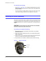
ACUIX™ Terminology
This document uses the following terms to describe the main hardware
components of the ACUIX PTZ dome:
xvi
Dome
The complete installed product including the housing,
mount or adapter, scan assembly, and bubble.
Housing
The in-ceiling, pendant, or rugged outer enclosure that
houses the scan assembly. It contains an interface board
for connecting power, video, control data, and alarm wiring
to the dome. The housing is a component of the dome.
Mount
The hardware used to support the housing. It may be
included with the housing (as with in-ceiling and rugged
housings) or available for purchase separately (as with
indoor or outdoor pendant housings). The mount is a
component of the dome.
Scan
Assembly
A combination of mechanical, electrical, and software
components, including the camera block and firmware. It is
installed inside the housing and enclosed by the bubble.
The scan assembly is a component of the dome.
Camera
The particular model of camera purchased. The camera is
a component of the scan assembly.
Bubble
The optically transparent hemisphere that fits onto the
bottom of the housing, enclosing the scan assembly. It is
available in clear or colored versions. The bubble is a
component of the dome.
ACUIX™ PTZ High Speed Analog Dome Installation and Configuration Guide
Document Conventions
This document uses the following conventions:
Typeface
Meaning
Example
Bold
User input
Type 1234.
OSD menu title/command
Select 2 Control Options 1 PASS.
BOLD CAPS
Key name
Press and hold CTRL.
Italic
Placeholder
Type user name.
Cross-reference
See Chapter 1, Introduction.
Text string displayed on the OSD menu
The message Unauthorized (object)
entered appears.
Typewriter
DANGER Indicates an imminently hazardous situation
which, if not avoided, will result in death or serious injury.
WARNING Indicates a potentially hazardous situation which, if
not avoided, could result in death or serious injury.
CAUTION Indicates a potentially hazardous situation which, if not
avoided, could result in minor or moderate injury.
CAUTION (without safety alert symbol) Indicates a potentially
hazardous situation which, if not avoided, could result in damage to
property.
Note
Document 800-05662V1 Rev A
04/11
Indicates important information that does not involve a significant risk
of personal injury or property damage.
xvii
xviii
1
Introduction
This chapter contains the following sections:
•
About the ACUIX™ High-Speed PTZ Dome, page 1
•
Setup and Configuration, page 2
•
Additional Information, page 2
About the ACUIX™ High-Speed PTZ Dome
The ACUIX High-Speed PTZ Dome is a fully featured pan/tilt/zoom (PTZ)
tracking system designed for detailed surveillance applications.
Dome features include:
•
True Day/Night (TDN), Wide Dynamic Range (WDR), and Electronic Image
Stabilization (EIS) options
•
Indoor and outdoor housing options, available in in-ceiling (indoor),
pendant (indoor/outdoor), and rugged (outdoor) styles. The outdoor
pendant housing features a sunshroud and heater and blower.
•
Ability to update firmware remotely without interrupting camera operation;
multiple domes can be updated simultaneously
•
Secure storage of all camera settings (such as labels, s, tours, and privacy
zones)
•
Active UTP video output
•
Up to 150 user-defined presets
•
Dynamic privacy zones that allow a user to mask up to 32 regions to ensure
absolute privacy for sensitive areas
•
Still Shot™ to freeze a scene and save storage space during tours
•
Password protection to prevent unauthorized users from changing system
settings
•
Multilanguage on-screen display (OSD) configuration menus
Document 800-05662V1 Rev A
04/11
1
Introduction
Setup and Configuration
Setting up a complete ACUIX system typically includes the following steps:
1. Installing the mount, adapter, or bracket to which the housing will be
attached.
2. Connecting the field wiring to the interface board inside the housing.
3. Installing the housing to the mounting surface.
4. Configuring the dome address, protocol, baud rate, and parity settings on
the scan assembly interface board.
5. Installing the scan assembly in the housing.
6. Installing the bubble.
7. Configuring additional dome settings remotely using the OSD menu.
The protocol and address settings of the dome are configured using DIP
switches located on the scan assembly. All other dome settings—such as
presets, preset tours, mimic tours, and privacy zones—are programmed using
OSD menus. A monitor and a controller are required to access the OSD.
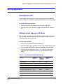
Additional Information
For the latest product information and documentation, visit the ACUIX PTZ dome
web page at www.honeywellvideo.com/products/cameras/pt/103879.html.
The product page contains downloadable PDF versions of data sheets, quick
references, installation and user guides, A&E specifications, product notices,
and other related documents.
2
2
Installing the Scan Assembly
This chapter contains the following sections:
•
Preparing to Install the Scan Assembly, page 3
•
Installing the Scan Assembly, page 8
•
Installing the Bubble, page 9
Preparing to Install the Scan Assembly
The dome housing must be completely installed prior to installing the scan
assembly and bubble. The ACUIX™ Indoor and Outdoor Housings Installation
Guide (800-04558) provides instructions for installing the housing.
Note
The instructions in this chapter assume that the housing has already
been installed, as well as all of the power, video, and telemetry (data)
connections.
Before you install the scan assembly in the housing, you must first set the dome
address, protocol, baud rate, and parity using the DIP switches located on the
circuit board on top of the scan assembly.
CAUTION To prevent damage to the housing and scan assembly
circuit boards, follow standard industry precautions for electrostatic
discharge sensitive devices.
Document 800-05662V1 Rev A
04/11
3
Installing the Scan Assembly
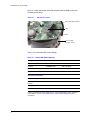
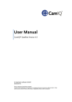
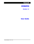
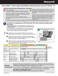
Figure 2-1 shows the location of the DIP switches (SW1 to SW6) on the scan
assembly circuit board.
Figure 2-1
DIP Switch Locations
SW1, SW2, SW3, and SW4
SW5
SW6
Scan assembly
(includes camera)
Table 2-1 lists the default DIP switch settings.
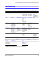
Table 2-1
Default DIP Switch Settings
Setting
Default
Switch
Address
1
SW1, SW2, SW3, and SW4
Protocol
MAXPRO-mode
SW5-1 to SW5-5
Baud rate
9600
SW6-1 to SW6-4
Parity
Even
SW6-5 SW6-6
Restore Factory Defaults
OFF
SW5-7
Overriding the Logical
Address
ON
SW5-8
Debugging/boot control
OFF
SW6-7
Reserved
OFF
SW6-8
Miscellaneous Defaults*
* These are advanced switch settings and it is not recommended to make changes to
these defaults. See the System Administration and Equipment Handling for more
information.
4
ACUIX™ PTZ High Speed Analog Dome Installation and Configuration Guide
Setting the Dome Address (SW1 to SW4)
Each dome requires a unique address. The range of acceptable addresses is
determined by the type of controller you are using. Some controllers allow
addresses between 1 and 128, while others allow addresses between 1 and 256.
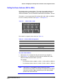
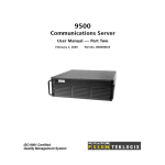
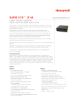
The address is set using the rotary DIP switches SW1, SW2, SW3, and SW4 on
the scan assembly circuit board (see Figure 2-1 and Figure 2-2).
Figure 2-2
Switches SW1 to SW4
Each switch is assigned a place value (see Table 2-2).
Table 2-2
Address Switch Assignments
Address
Value
SW1
Units digit
SW2
Tens digit
SW3
Hundreds digit
SW4
Thousands digit
To set the dome address:
1. Remove the scan assembly from the pink antistatic bag it shipped in.
2. Using Table 2-2 as a reference, turn the arrows on switches SW1, SW2,
SW3 and SW4 to select the address you want.
For example:
•
•
To set the dome address to 0001, set SW1=1, SW2=0, SW3=0, SW4=0.
To set the dome address to 0125, set SW1=5, SW2=2, SW3=1, SW4=0.
Note
If the address is set to 0000, the dome responds to control
commands for any address. For example, if an operator sends control
commands to address 0002, the dome that has the address 0000
performs the same commands.
Document 800-05662V1 Rev A
04/11
5
Installing the Scan Assembly
Setting the Protocol (SW5)
The ACUIX PTZ dome supports the following protocols for communicating with
other devices:
•
•
•
•
•
IntelliBus™
MAXPRO-mode
VCL
Diamond
Pelco P, Pelco D, Pelco P_AD, Pelco D_AD
Select a protocol that is compatible with the controller or other device that you
want to connect to.
The protocol is set using DIP switch SW5 on the circuit board (see Table 2-3).
The factory default is MAXPRO-mode (a mode of using Diamond protocol which
has special presets for functions beyond pan, tilt, zoom, focus, and preset).
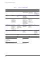
Table 2-3
Protocol Name
SW5 Protocol Settings
Switch Position
1
2
3
4
5
6
7
8
IntelliBus™
OFF
OFF
OFF
OFF
OFF
OFF
OFF
ON
MAXPRO-mode (default)
OFF
ON
OFF
OFF
OFF
OFF
OFF
ON
VCL - RS485
ON
ON
OFF
OFF
OFF
OFF
OFF
ON
VCL UTC
("Up-the-Coax")
OFF
OFF
ON
OFF
OFF
OFF
OFF
ON
Diamond
ON
OFF
OFF
OFF
OFF
OFF
OFF
ON
Pelco P
ON
OFF
ON
OFF
OFF
OFF
OFF
ON
Pelco D
OFF
ON
ON
OFF
OFF
OFF
OFF
ON
Pelco P_AD
ON
OFF
ON
OFF
ON
OFF
OFF
ON
Pelco D_AD
OFF
ON
ON
OFF
ON
OFF
OFF
ON
To set the protocol:
•
Using Table 2-3 as a reference, position the pins on switch SW5 to
correspond to the protocol that you have selected.
Note
6
Normally, pin 8 should be set to the ON position. Setting the switch to
OFF allows the address, protocol, baud rate, and parity settings to be
changed from the OSD, which is not recommended for most
installations.
ACUIX™ PTZ High Speed Analog Dome Installation and Configuration Guide
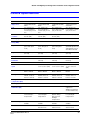
Setting the Baud Rate and Parity (SW6)
The baud rate and parity settings are determined by the protocol that you have
selected. Table 2-4 lists the baud rate and parity settings that correspond to each
protocol.
Table 2-4
Baud Rate and Parity Settings by Protocol
Protocol
Baud Rate and Parity
IntelliBus™
38400 baud, no parity
MAXPRO-mode (default)
9600 baud, even parity
VCL - RS485
9600 baud, no parity
VCL UTC
9600 baud, no parity
Diamond
9600 baud, even parity
Pelco P
4800 baud, no parity
Pelco D
2400 baud, no parity
Pelco P_AD
4800 baud, no parity
Pelco D_AD
2400 baud, no parity
The baud rate and parity are set using DIP switch SW6 (see Table 2-5). The
factory default is 9600 baud, even parity.
Table 2-5
Values
SW6 Baud Rate and Parity Settings
Baud Rate Switch Position
Parity Switch
Position
Other*
1
2
3
4
5
6
7
8
600
OFF
OFF
OFF
OFF
1200
ON
OFF
OFF
OFF
2400
OFF
ON
OFF
OFF
4800
ON
ON
OFF
OFF
9600
OFF
OFF
ON
OFF
19200
ON
OFF
ON
OFF
38400
OFF
ON
ON
OFF
57600
ON
ON
ON
OFF
115200
OFF
OFF
OFF
ON
None
OFF
OFF
OFF
OFF
Even
ON
OFF
OFF
OFF
Odd
OFF
ON
OFF
OFF
* The default position for pins 7 and 8 is OFF (see Table 2-1).
Document 800-05662V1 Rev A
04/11
7
Installing the Scan Assembly
To set the baud rate and parity:
•
Using Table 2-4 and Table 2-5 as a reference, position the pins on switch
SW6 to correspond to the baud rate and parity values of the protocol that
you have selected.
If any of the settings on SW5 or SW6 are invalid, the system reverts to the
factory default settings: MAXPRO-mode at 9600 baud, even parity.
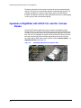
Installing the Scan Assembly
After you have set the dome address, protocol, baud rate, and parity on the scan
assembly circuit board, you can install the scan assembly in the housing. The
installation procedure is the same for all housing styles (in-ceiling, pendant, or
rugged).
CAUTION Do not remove the camera from the scan assembly.
Handle the camera lens with extreme care.
To install the scan assembly in the housing:
1. Remove the plastic lens cap and foam insert from the scan assembly.
Do not touch the lens.
2. Rotate and line up the yellow label on the scan assembly with the yellow
label on the housing.
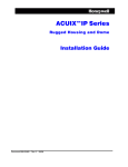
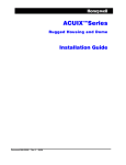
3. Gently push the scan assembly into the housing until the two locking tabs
on the scan assembly snap into the guides on the housing.
4. Ensure that the scan assembly is attached securely inside the housing.
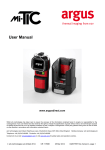
Figure 2-3
ACUIX Scan Assembly
Locking tab
Yellow label
8
ACUIX™ PTZ High Speed Analog Dome Installation and Configuration Guide
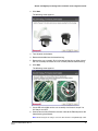
Installing the Bubble
After you have installed the scan assembly in the housing, and the camera lens
cap has been removed, you can install the bubble.
The installation procedure is slightly different for each type of housing.
Attaching the Bubble to an In-Ceiling Housing
To attach the bubble to the housing:
1. Attach the safety cable from the bubble to the bracket inside the housing.
2. Align the three hooks on the bubble with the three mounting posts on the
housing.
3. Turn the bubble clockwise to lock it into the housing.
Figure 2-4
Document 800-05662V1 Rev A
04/11
In-Ceiling Housing Bubble Installation
9
Installing the Scan Assembly
Attaching the Bubble to an Indoor or Outdoor Pendant Housing
To attach the bubble to the housing:
1. Clip the safety cable to the bracket on the housing.
2. Confirm that the o-ring is in place around the bubble and gently push the
bubble against the housing
3. Install the two screws on the housing to secure the bubble in place.
Figure 2-5
Pendant Housing Bubble Installation
Safety cable
Attaching the Bubble to a Rugged Housing
To attach the bubble to the housing:
1. Clip the safety cable to the bracket on the housing.
2. Align the four screw holes on the bubble with the four holes on the housing.
3. Push the bubble against the housing and tighten the four captive security
screws using the supplied 5/32-inch (4 mm) hex key.
Figure 2-6
10
Rugged Housing Bubble Installation
3
Preparing to Configure the Dome
This chapter contains the following sections:
•
Pre-Configuration Checklist, page 11
•
Accessing the Main Menu, page 12
•
Navigating OSD Menus, page 13
•
Sending the Dome to a Preset, page 13
•
Special Presets, page 14
•
OSD Menu Tree, page 15
Pre-Configuration Checklist
After you have installed the PTZ dome, you are ready to begin configuring the
dome settings from the OSD menu. To do this, you will need a keyboard
controller and a monitor.
The ACUIX High-Speed PTZ Dome is compatible with all Honeywell controllers,
including the UltraKey Touch, UltraKey Lite, UltraKey Plus, HJZTP, HKJMMTP,
and HEGS5300. It is also compatible with third-party controllers using Pelco P or
Pelco D control protocols.
Before you begin configuring the dome, do the following:
1. Make sure the dome is assigned to the controller you are using. The dome
address (for example, CAM 001) should appear on the controller LCD
display.
2. Turn on the dome.
3. Confirm that video is displaying on the monitor. A startup screen should
appear showing the protocol, baud rate, parity, data bits, camera type, and
firmware version of the dome.
4. If the dome does not "find home" automatically, enter a control command
(such as moving the joystick left or right). The message Finding Home...
appears, followed by Home Found.
Document 800-05662V1 Rev A
04/11
11
Preparing to Configure the Dome
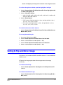
Accessing the Main Menu
To begin configuring the dome settings, call up the main menu on your monitor
screen using special preset 90.
Note
Because the ACUIX High-Speed PTZ Dome is designed to work with
a wide variety of devices and protocols, all possible ways to perform a
task are not given here. The instructions in this guide are intended to
supplement the instructions provided in your controller’s user guide.
To access the main menu:
•
Enter preset 90 on your controller.
On the UltraKey Touch controller, press View, type 90, and then press Enter.
On the HJZTP controller, type 90, and then press Preset.
The main menu (Figure 3-1) appears.
Figure 3-1
OSD Main Menu
---ACUIX Dome
---Camera............35x WDR&FNR
----------------------------1 Language............English
2 Display Options
3 Control Options
4 Diagnostic Options
5 Camera Options
6 Function Programming
7 Enhanced Settings
IRIS CLOSE to Exit
12
ACUIX™ PTZ High Speed Analog Dome Installation and Configuration Guide
Navigating OSD Menus
You can navigate through the menu options displayed on the monitor using the
following controller commands:
•
To navigate vertically through the menu options, move the controller joystick
up or down.
•
To select a menu option, or to toggle between settings, press Iris Open (Iris+).
•
To exit a menu and return to the previous screen, press Iris Close (Iris −).
Sending the Dome to a Preset
A preset is a memorized dome function that can be recalled manually by the
operator.
•
To go to a preset using the UltraKey Touch controller, press View, type preset
number, and then press Enter.
•
To go to a preset using the HJZTP controller, type preset number, and then
press Preset.
Document 800-05662V1 Rev A
04/11
13
Preparing to Configure the Dome
Special Presets
Special presets 72 to 99 are reserved for controlling and programming the dome.
Table 3-1
Preset
Function
Protocol
72
Recover encrypted user login
Diamond, IntelliBus™, MAXPRO-mode,
VCL, VCL UTC, Pelco P, Pelco D, AD
73
Enable broadcast command receive mode
74
Disable broadcast command receive mode
Diamond, MAXPRO-mode, VCL,
VCL UTC, Pelco P, Pelco D, AD
75
Administrator/password/PIN settings:
• User login PIN
• Change PIN
• System info
• Change address, protocol
Diamond, IntelliBus™, MAXPRO-mode,
VCL, VCL UTC, Pelco P, Pelco D, AD
76
Run mimic tour 1–16
77
Program mimic tour
78
Run preset tour 1–16
79
User default setting preset
All
80, 81, 82
Run mimic tours 1, 2, and 3
83, 84, 85
Program mimic tours 1, 2, and 3
MAXPRO-mode, VCL, VCL UTC,
Pelco P, Pelco D, AD, Pelco P_AD,
Pelco D_AD
86
End mimic tour programming mode
MAXPRO-mode, VCL, VCL UTC, Pelco P,
Pelco D, AD
87, 88, 89
Start/run preset tours 1, 2 and 3
MAXPRO-mode, VCL, VCL UTC,
Pelco P, Pelco D, AD, Pelco P_AD,
Pelco D_AD
90
Setup menu (OSD)
MAXPRO-mode, VCL, VCL UTC, Pelco P,
Pelco D, AD
91
Reserved
92
Toggle auto exposure on or off
93
Toggle backlight compensation on or off
94
Toggle between day mode and night modea
95
Toggle between freezing and unfreezing the current scenea
96
Run flashback function (toggle between two saved positions)
97
Advanced preset
a
MAXPRO-mode, VCL, VCL UTC,
Pelco P, Pelco D, AD
MAXPRO-mode, VCL, VCL UTC, Pelco P,
Pelco D, AD
All
98
Camera reset
Diamond, IntelliBus, MAXPRO-mode,
VCL, VCL UTC, Pelco P, Pelco D, AD
99
Toggle between day mode and night modea
Diamond, IntelliBus
a
14
Special Presets
Camera model dependent
ACUIX™ PTZ High Speed Analog Dome Installation and Configuration Guide
OSD Menu Tree
Table 3-2
Menu Tree - 18× Color (HDXA), 18× WDR/TDN (HDXJ), 26× WDR/TDN (HDXF)
1. Language
English (default), Français (French), Deutsch (German), Italiano (Italian), Español (Spanish), Polski (Polish), Nederlands (Dutch), Čeština (Czech)
2. Display Options
3. Control Options
4. Diagnostic Options
5. Camera Options
6. Function Programming
7. Enhanced Features
1. Camera Msg
1. PASS
1. Coordinates
1. Zoom and Focus
(1) Max Digital Zoom Mag
(2) Manual Zoom Speed
(3) Min Focus Length(cm)
1. PTZ Mimic Tour Menua
(1) Run a Mimic Tour
(2) Program a Mimic Tour
(3) Delete a Mimic Tour
1. Video Gain/PWM
Settings
(1) Video Gain (UTP)
(2) Lift PWM Level 0-100
(3) Gain PWM Level 0-100
(4) Char White Level 0-100
2. Sectors
2. Auto-Pivot
2. Total Run Time (PTZ,
IR&Fo)
2. Exposure Control
(1) NA
(2) Exposure Level
(3) NA
(4) NA
(5) NA
(6) NA
(7) Auto Slow Shutter
(8) Backlight Comp
2. Program a Preset
Tourb
2. NA
3. Program Alarms
3. Clear The Memory
3. NightShot Control c
(1) NightShot Mode
(2) NightShot
(3) Activate
(4) Deactivate
3. Privacy Zone Options
(1) Change PrivZone
Priority
(2) Enable/Disable
PrivacyZone
(3) Privacy Zone Color
(4) Delete Privacy Zone
3. NA
3. Preset Names
(1) Program Alarms
(2) Set Alarm Condition
(3) Enable Auto Ack
(4) Enter Alarm Message
(5) Alarm Overwrite
(6) Overwrite Time (sec)
4. Digital Zoom Mag
4. Set Pan and Tilt
Options
(1) Manual Speed deg/s
(2) Pan Reverse
(3) Tilt Reverse
(4) −5 deg Tilt Limit
(5) Find Home on Startup
(6) Pan Offset
(7) Startup State Restore
4. Operational
Diagnostics
(1) Display Error Logs
(2) Clear Error Logs
(3) Run Diagnostics ( Find
Home, Check Supply
Voltage)
4. White Balance
(1) High Light WB Mode
(2) Low Light WB Mode
(3) Enter High Lght 28dB
(4) Enter Low Lght 28dB
(5) Manual White Balance
(6) Red Gain
(7) Blue Gain
4. List PS/PT/Sectors
(1) Presets
(2) Preset Tours
(3) Sectors
4. NA
5. Start-up Screen Msg
5. Set Default Function
5. NA
5. Video Optionsc
(1) Still Preset
(2) E-Flip
(3) Mirror Image
5. Program Sectorb
5. Time & Date Settings
(1) Display Time
(2) Display Date
(3) Time Format
(4) Change Time
(5) Change Date
6. Change Camera Name
Loc.
6. Auto Focus
6. Restore Default
Settings
6. Vert Phase Edge
6. Program Privacy Zoneb
6. Display Supply
Voltages
7. Change Sector Name
Loc.
7. Preset Tour Auto Foc
7. Scan and Camera
Reset
7. Vert Phase 0–359.9
7. Delete PS/PT/MT/
Sectorsb
7. Timed Functions
8. Crosshairs
8. Preset Auto Focus
8. NA
9. Dome Name Settings
(1) Set Dome Name
(2) Display Dome Name
(3) Change Dome Name
Location
9. Timed Auto Focus (sec)
9. WDR & Motion
Detectionc
(1) Wide Dynamic Range
(2) Motion Detection
a
Diamond/IntelliBus™ protocol only
MAXPRO-mode/VCL/VCL UTC/Pelco P/Pelco D/AD/Pelco P_AD/Pelco D_AD protocol only
c Not available with 18× Color (HDXA) cameras
b
Document 800-05662V1 Rev A
04/11
15
Preparing to Configure the Dome
Table 3-3
Menu Tree - 35× WDR/TDN (HDXG)
1. Language
English (default), Français (French), Deutsch (German), Italiano (Italian), Español (Spanish), Polski (Polish), Nederlands (Dutch), Čeština (Czech)
2. Display Options
3. Control Options
4. Diagnostic Options
5. Camera Options
1. Camera Msg
1. PASS
1. Coordinates
1. Zoom and Focus
(1) Max Digital Zoom Mag
(2) Min Focus Length(cm)
6. Function Programming
7. Enhanced Features
1. PTZ Mimic Tour Menua
1. Video Gain/PWM
Settings
(1) Video Gain (UTP)
(2) Lift PWM Level 0-100
(3) Gain PWM Level 0-100
(4) Char White Level 0-100
(1) Run a Mimic Tour
(2) Program a Mimic Tour
(3) Delete a Mimic Tour
2. Sectors
2. Auto-Pivot
2. Total Run Time (PTZ,
IR&Fo)
2. Exposure Control
(1) Auto AE Mode
(2) Manual AE Mode
(3) Full Manual Settings
(4) Slow AE Response
2. Program a Preset Tourb 2. Display Temperature
3. Preset Names
3. Program Alarms
(1) Program Alarms
(2) Set Alarm Condition
(3) Enable Auto Ack
(4) Enter Alarm Message
(5) Alarm Overwrite
(6) Overwrite Time (sec)
3. Clear The Memory
3. Video Setup
(1) Exposure Level
(2) Max AGC Level 0-255
(3) Chroma Level 0-255
(4) Backlight Comp
(5) Auto SlowShutter Lim
(6) Wide Dynamic Range
(7) Advanced WDR
(8) High Sensitivity Mode
(9) Field Noise Reduction
3. Privacy Zone Options
(1) Change PrivZone
Priority
(2) Enable/Disable
PrivacyZone
(3) Privacy Zone Color
(4) Delete Privacy Zones
3. Temp. format
4. Digital Zoom Mag
4. Set Pan and Tilt
Options
(1) Manual Speed deg/s
(2) Pan Reverse
(3) Tilt Reverse
(4) −5 deg Tilt Limit
(5) Find Home on Startup
(6) Pan Offset
(7) Startup State Restore
4. Operational
Diagnostics
(1) Display Error Logs
(2) Clear Error Logs
(3) Run Diagnostics ( Find
Home, Check Supply
Voltage)
4. White Balance
(1) Manual White Balance
(2) Red Gain 0-511
(3) Blue Gain 0-511
4. List PS/PT/Sectors
(1) Presets
(2) Preset Tours
(3) Sectors
(4) Preset Types
4. NA
5. Start-up Screen Msg
5. Set Default Function
5. NA
5. Video Options
(1) Still Preset
(2) E-Flip
(3) Mirror Image
5. Program Sectorb
5. Time & Date Settings
(1) Display Time
(2) Display Date
(3) Time Format
(4) Change Time
(5) Change Date
6. Change Camera Name
Loc.
6. Auto Focus
6. Restore Default
Settings
6. Vert Phase Edge
6. Program Privacy Zoneb
6. Display Supply
Voltages
7. Change Sector Name
Loc.
7. Preset Tour Auto Foc
7. Scan and Camera
Reset
7. Vert Phase 0–359.9
7. Delete PS/PT/MT/
Sectorsb
7. Timed Functions
8. Crosshairs
8. Preset Auto Focus
8. Image Stabilization
9. Dome Name Settings
(1) Set Dome Name
(2) Display Dome Name
(3) Change Dome Name
Location
9. Timed Auto Focus (sec)
9. Motion Detection
a
b
Diamond/IntelliBus™ protocol only
MAXPRO-mode/VCL/VCL UTC/Pelco P/Pelco D/AD/Pelco P_AD/Pelco D_AD protocol only
16
4
Configuring the OSD
This chapter contains the following sections:
•
Changing the OSD Language, page 17
•
Displaying the Dome Address, page 18
•
Displaying Sectors and Presets, page 18
•
Displaying the Zoom Magnification, page 19
•
Displaying the Startup Screen, page 19
•
Displaying Crosshairs, page 19
•
Displaying Dome Names, page 20
•
Displaying the Pan, Tilt, and Zoom Coordinates, page 20
•
Displaying the Time and Date, page 21
Changing the OSD Language
By default, the on-screen display (OSD) menus are in English.
To change the OSD language:
1. Select 1 Language.
2. Press Iris Open to navigate to the desired language: Français (French),
Deutsch (German), Italiano (Italian), Español (Spanish), Polski (Polish),
Nederlands (Dutch), or Čeština (Czech).
Document 800-05662V1 Rev A
04/11
17
Configuring the OSD
Displaying the Dome Address
Each dome on your network is assigned a unique identifier (for example, CAM 001).
This is the dome address. You can show the dome address on the screen.
To show/hide the dome address:
•
Select 2 Display Options 1 Camera Msg ON or OFF (default)
To change the location of the dome address on the screen:
1. Select 2 Display Options 6 Change Camera Name Loc.
2. Position the dome address on the screen by moving the controller joystick
up or down.
Displaying Sectors and Presets
After you have programmed sectors and presets (see Configuring Presets,
Tours, Privacy Zones, and Sectors on page 55), you can show the current sector
and/or preset on the screen.
To show/hide the sector name:
•
Select 2 Display Options 2 Sectors ON or OFF (default)
Note
If the dome has overlapping sectors displaying at the same time, the
two sector names alternate on the screen at 1.5 second intervals.
To change the location of the sector name on the screen:
1. Select 2 Display Options 7 Change Sector Name Loc.
2. Position the sector name on the screen by moving the controller joystick up
or down.
To show/hide the preset name:
•
18
Select 2 Display Options 3 Preset Names ON or OFF (default)
ACUIX™ PTZ High Speed Analog Dome Installation and Configuration Guide
Displaying the Zoom Magnification
You can show the camera’s zoom magnification level on the screen.
To show/hide the zoom magnification:
•
Select 2 Display Options 4 Digital Zoom Mag ON or OFF (default).
Displaying the Startup Screen
A startup screen appears when you first power up the dome, displaying the
protocol, baud rate, parity, data bits, camera type, and firmware version of the
dome. You can turn off the startup screen so that it does not appear the next time
you power up the dome.
To show/hide the startup screen message:
•
Select 2 Display Options 5 Start-up Screen Msg ON (default) or
OFF.
Displaying Crosshairs
You can show crosshairs on the screen to aid in positioning the camera. This is
helpful for setting up privacy zones and sectors.
To show/hide crosshairs:
•
Document 800-05662V1 Rev A
04/11
Select 2 Display Options 8 Crosshairs ON or OFF (default).
19
Configuring the OSD
Displaying Dome Names
You can create a dome name and manage its on-screen display settings.
To create a dome name:
1. Select 2 Display Options 9 Dome Name Settings 1 Set Dome
Name.
2. Enter a name for the dome (up to 24 alphanumeric characters) using the
controller joystick.
To show/hide a dome name:
•
Select 2 Display Options 9 Dome Name Settings 2 Display Dome
Name ON or OFF (default).
To change the location of the dome name on the screen:
1. Select 2 Display Options 9 Dome Name Settings 3 Change Dome
Name Location.
2. Position the dome name on the screen by moving the controller joystick up
or down.
Displaying the Pan, Tilt, and Zoom Coordinates
You can show the dome’s pan (azimuth), tilt (elevation/declination), and zoom
coordinates on the screen.
To show/hide the pan and tilt coordinates:
•
20
Select 4 Diagnostic Options 1 Coordinates ON or OFF (default).
ACUIX™ PTZ High Speed Analog Dome Installation and Configuration Guide
Displaying the Time and Date
You can show the current time and date on the screen. The time is displayed at
the lower left center of the screen, the date at the lower right center of the screen.
To show/hide the current time:
•
Select 7 Enhanced Settings 5 Time & Date Settings 1 Display Time
ON or OFF (default).
To change the time setting:
1.
Select 7 Enhanced Settings 5 Time & Date Settings 4 Change Time.
2.
Enter the new time in HH:MM:SS (hours:minutes:seconds) format using the
controller joystick.
3.
Press Iris Open to accept the new time, or press Iris Close to cancel.
To change the time format:
•
Select 7 Enhanced Settings 5 Time & Date Settings 3 Time Format
24 Hours (default) or 12 Hours.
To show/hide the current date:
•
Select 7 Enhanced Settings 5 Time & Date Settings 2 Display Date
ON or OFF (default).
To change the date:
1.
Select 7 Enhanced Settings 5 Time & Date Settings 5 Change Date.
2. Enter the new date in YYYY-MM-DD (year-month-day) format using the
controller joystick.
3. Press Iris Open to accept the new time, or press Iris Close to cancel.
Document 800-05662V1 Rev A
04/11
21
Configuring the OSD
22
5
Configuring PTZ Control
This chapter contains the following sections:
•
Setting PASS, page 23
•
Setting Auto Pivot, page 24
•
Setting the Pan and Tilt Speed, page 24
•
Setting Pan Reverse, page 24
•
Setting Tilt Reverse, page 25
•
Setting the Tilt Limit, page 25
•
Finding Home on Startup, page 25
•
Setting the Pan Offset, page 26
•
Setting the Startup State Restore, page 27
•
Setting Auto Focus, page 27
•
Setting Timed Auto Focus, page 28
Setting PASS
PASS adjusts the pan and tilt speed in proportion to the amount of zoom so that
the image on the monitor appears to be moving at the same speed when
zooming in and out. When PASS is enabled, the pan and tilt speed is slowed at
telephoto zoom settings, making it easier to position the camera.
To enable/disable PASS:
•
Document 800-05662V1 Rev A
04/11
Select 3 Control Options 1 PASS ON (default) or OFF.
23
Configuring PTZ Control
Setting Auto Pivot
Auto pivot lets you track subjects passing under the dome in a single continuous
shot. When auto pivot is enabled and the controller joystick is held in the down
position, the camera automatically turns 180 degrees when it reaches its lower
limit and continues tracking up the other side.
To enable/disable auto pivot:
•
Select 3 Control Options 2 Auto-Pivot ON or OFF (default).
Setting the Pan and Tilt Speed
You can manually set the maximum pan and tilt speed settings of the camera.
The following maximum pan speeds are available:
•
120 degrees per second
•
240 degrees per second
•
480 degrees per second
The maximum tilt speed is determined by the maximum pan speed, being half of
the maximum pan speed: 60, 120, or 240 degrees per second.
To manually set the maximum pan and tilt speed:
•
Select 3 Control Options 4 Set Pan and Tilt Options 1 Manual
Speed deg/s 120, 240, or 480 (default).
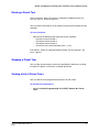
Setting Pan Reverse
You can reverse the pan so that a left pan command from the controller will
cause the camera to pan right and a right pan command will cause the camera
to pan left.
To enable/disable pan reverse:
•
24
Select 3 Control Options 4 Set Pan and Tilt Options 2 Pan Reverse
ON or OFF (default).
ACUIX™ PTZ High Speed Analog Dome Installation and Configuration Guide
Setting Tilt Reverse
You can reverse the tilt so that a tilt up command from the controller will cause
the camera to tilt down and a tilt down command will cause the camera to tilt up.
To enable/disable tilt reverse:
•
Select 3 Control Options 4 Set Pan and Tilt Options 3 Tilt Reverse
ON or OFF (default).
Setting the Tilt Limit
You can allow the camera to tilt five degrees above the horizontal using the −5
degree tilt limit feature.
To enable/disable −5 degree tilt limit:
•
Select 3 Control Options 4 Set Pan and Tilt Options 4 −5 deg Tilt
Limit ON or OFF (default).
Finding Home on Startup
By default, the dome automatically "finds home" on startup. You can disable this
setting if you want the dome to wait for a control input from the operator before
going to its "home" (index) position. To disable this setting, the Startup State
Restore must be set to OFF.
Note
Document 800-05662V1 Rev A
04/11
When a privacy zone is enabled, no video is displayed during the
finding home process. Privacy zones are not recognized until the
dome reaches home. After home is found, video is displayed on the
monitor unless a privacy zone overlaps with this home setting.
25
Configuring PTZ Control
To enable/disable finding home on startup:
1. If necessary, disable Startup State Restore (see Setting the Startup State
Restore on page 27).
2. Select 3 Control Options 4 Set Pan and Tilt Options 5 Find Home
on Startup ON (default) or OFF.
3. If ON is selected, the following message appears:
Extreme Caution: This will cause the scan to move immediately
on startup. Are you sure that you want to do this? Y/N.
Select Y (yes) to continue, or select N (no) to cancel.
Setting the Pan Offset
The pan offset feature is useful when a new scan assembly is installed and the
programming from the existing ACUIX is transferred to the new ACUIX using the
upload/download feature.
The alignment of the new ACUIX may not be exactly the same as the old ACUIX,
causing the programmed positions of the presets to be off. Preset 0 is used to
define the location of the pan setting. To set the pan offset, you must know the
original positioning of preset 0.
To set the pan offset:
1. Select 3 Control Options 4 Set Pan and Tilt Options 6 Pan Offset
1 Pan Offset ON.
2. Exit the OSD menus until you have manual control of the dome.
3. Enter preset 0 on your controller. If the dome does not go to the previously
known position for preset 0, the pan offset function cannot be used.
4. Using the controller, position the dome where preset 0 should be.
5. Select 3 Control Options 4 Set Pan and Tilt Options 6 Pan Offset
2 Set Pan Offset.
6. Test the setting. Using the controller, reposition the dome and then enter
preset 0. The dome should return to the programmed position.
26
ACUIX™ PTZ High Speed Analog Dome Installation and Configuration Guide
Setting the Startup State Restore
By default, the dome automatically "finds home" on startup. When this function
is enabled, the dome will find home on startup and then revert to the position it
was at prior to the last shutdown, as well as the function it was executing prior to
the last shutdown.
To enable/disable startup state restore:
1. Select 3 Control Options 4 Set Pan and Tilt Options 7 Startup State
Restore ON (default) or OFF.
2. If ON is selected, the following message appears:
Extreme Caution: This will move the dome to previous shutdown
position on startup. Are you sure that you want to do this? Y/N.
Select Y (yes) to continue, or select N (no) to cancel.
Setting Auto Focus
Auto focus causes the lens to remain in focus when using zoom and/or pan and
tilt functions. The following auto focus settings are available:
•
Z: The camera focuses automatically when the zoom setting changes.
•
PTZ: The camera focuses automatically when using PTZ functions.
•
OFF: The focus is operated manually using the controller.
To set auto focus:
•
Select 3 Control Options 6 Auto Focus Z (default), PTZ, or OFF.
To set preset and preset tour auto focus, see Setting Preset Auto Focus on page
56 and Setting Preset Tour Auto Focus on page 60.
Document 800-05662V1 Rev A
04/11
27
Configuring PTZ Control
Setting Timed Auto Focus
You can set the camera to focus automatically at regular intervals of either 20,
30, 60, 120, 300, or 600 seconds.
To set timed auto focus:
•
28
Select 3 Control Options 9 Timed Auto Focus (sec) OFF (default),
20, 30, 60, 120, 300, or 600.
6
Configuring HDXA, HDXJ, and HDXF
Camera Settings
This chapter contains the following sections:
•
Setting the Zoom, page 29
•
Setting Exposure, page 31
•
Setting NightShot (True Day/Night), page 32
•
Setting White Balance, page 34
•
Setting E-Flip and Mirror Image, page 35
•
Setting the Vertical Phase Edge, page 36
•
Setting Wide Dynamic Range, page 36
•
Setting Motion Detection, page 37
•
Setting the Video Gain and Lift (UTP Video Output), page 38
Setting the Zoom
Setting the Maximum Digital Zoom
Digital zoom enlarges an image by expanding it both vertically and horizontally,
resulting in an overall reduction in resolution. You can limit the amount of digital
zoom available to the camera.
To set the maximum digital zoom:
•
Document 800-05662V1 Rev A
04/11
Select 5 Camera Options 1 Zoom and Focus 1 Max Digital Zoom
Mag 1× (default), 12×, 4×, or 2×.
29
Configuring HDXA, HDXJ, and HDXF Camera Settings
Setting the Zoom Speed
You can set the speed at which the camera goes from full wide zoom to
telephoto zoom. There are eight levels of zoom speed available.
To set the zoom speed:
1. Select 5 Camera Options 1 Zoom and Focus 2 Manual Zoom
Speed.
2. Select a value between 0 and 8 to set the zoom speed:
•
6 (default)
•
0 (slowest)
•
7 (fastest)
•
8 (zoom speed proportional to amount of joystick deflection)
Setting the Minimum Focus Distance
You can define the minimum focus distance to prevent the camera from focusing
on dirt or rain drops on the surface of the bubble. The minimum focus distance
is independent of the digital zoom.
To set the minimum focus distance:
1. Select 5 Camera Options 1 Zoom and Focus 3 Min Focus
Length(cm).
2. Select the minimum focus distance you want to use (see Table 6-1).
Table 6-1
30
Minimum Focus Distances by Camera
Wide End
Tele End
HDXA - 18× Color
29 cm
80 cm (default)
HDXJ - 18× WDR/TDN
29 cm
80 cm (default)
HDXF - 26× WDR/TDN
32 cm
150 cm (default)
ACUIX™ PTZ High Speed Analog Dome Installation and Configuration Guide
Setting Exposure
Auto Exposure
You can toggle auto exposure on or off using special preset 92 when the dome
is configured for MAXPRO-mode/VCL/VCL UTC/Pelco P/Pelco D protocol.
To enable/disable auto exposure:
1. Exit the OSD menus until you have manual control of the dome.
2. Enter preset 92 on your controller to toggle auto exposure on (default) or
off.
3. Enter preset 90 on your controller to return to the OSD main menu.
Manual Exposure Control
You can manually control the exposure by selecting a value between 0 and 14,
where 0 is for dark applications and 14 is for bright applications.
To learn more about manual exposure control, see About ACUIX PTZ Dome
Manual Exposure Control on page 100.
To set the exposure:
1. Select 5 Camera Options 2 Exposure Control 2 Exposure Level.
2. Select a value between 0 and 14 (default = 7).
Auto Slow Shutter
You can set the camera to automatically slow the shutter time when low light is
detected. However, slow shutter times beyond 1/60 s (1/50 s) can cause motion
blurring at low light levels.
To enable/disable auto slow shutter:
•
Select 5 Camera Options 2 Exposure Control 7 Auto Slow Shutter
ON or OFF (default).
Note
Document 800-05662V1 Rev A
04/11
Wide dynamic range mode is disabled when the auto slow shutter
limit is reached. It cannot be enabled while auto slow shutter is on.
31
Configuring HDXA, HDXJ, and HDXF Camera Settings
Backlight Compensation
Backlight compensation (BLC) corrects for strong background lighting by
enhancing subjects in the foreground, providing detail that would normally be
silhouetted.
You can turn backlight compensation on or off by using special preset 93 when
the dome is configured for MAXPRO-mode/VCL/VCL UTC/Pelco P/Pelco D
protocol.
Note
In most applications, wide dynamic range may be a better option than
backlight compensation.
To enable/disable backlight compensation:
1. Ensure that auto exposure is on (preset 92).
2. Do one of the following:
•
Enter preset 93 on your controller.
•
Select 5 Camera Options 2 Exposure Control 8 Backlight
Compensation ON or OFF (default).
Setting NightShot (True Day/Night)
This feature is only available with HDXJ and HDXF cameras. It is not available with
HDXA cameras.
When NightShot, or True Day/Night (TDN), is enabled, all available visible and IR
light is allowed to reach the image sensor and be recorded, producing a black
and white picture at the lowest possible light level.
You can configure the specific values at which the camera switches from day
mode (color, insensitive to IR) to night mode (black and white, sensitive to IR)
and from night mode to day mode. These are the activate and deactivate points.
The full list of values from highest light level to lowest light level is shown in
Table C-1 on page 103.
The deactivate point must always be at a higher light level (lower video gain and
lower shutter time) than the activate point. To ensure the highest quality picture,
the deactivate point should be set to 0 dB and 1/60 s, with the activate point set
far enough below it that the camera does not oscillate between day and night
modes. If the camera continually switches between day mode and night mode,
move the deactivate and activate points farther apart.
32
ACUIX™ PTZ High Speed Analog Dome Installation and Configuration Guide
To set the NightShot mode (manual or automatic):
1. Ensure that auto exposure is on (preset 92).
2. Select 5 Camera Options 3 NightShot Control 1 NightShot Mode
MAN (default) or AUTO.
To enable/disable NightShot:
1. Set NightShot mode to manual.
2. Select 5 Camera Options 3 NightShot Control 2 NightShot ON
or OFF (default).
Note
Wide dynamic range mode is disabled when the camera enters
NightShot mode. It cannot be enabled while NightShot is on.
To set the NightShot activate point:
1. Set the NightShot mode to automatic.
2. Select 5 Camera Options 3 NightShot Control 3 Activate.
3. Select the desired activate setting by moving the controller joystick up or
down to navigate through the available video gain and shutter speed
values.
Video Gain Settings
•
0 dB, 2 dB, 4 dB, 6 dB, 8 dB, 10 dB, 12 dB, 14 dB, 16 dB, 18 dB,
20 dB (default), 22 dB, 24 dB, 26 dB, or 28 dB
Shutter Speed Settings
Document 800-05662V1 Rev A
04/11
•
NTSC = 1/4 s, 1/8 s, 1/15 s, 1/30 s, or 1/60 s (default)
•
PAL = 1/3 s, 1/6 s, 1/12 s, 1/25 s, or 1/50 s (default)
33
Configuring HDXA, HDXJ, and HDXF Camera Settings
To set the NightShot deactivate point:
1. If necessary, set the NightShot mode to automatic.
2. Select 5 Camera Options 3 NightShot Control 4 Deactivate.
3. Select the desired deactivate setting by moving the controller joystick up or
down to navigate through the available video gain and shutter speed
values.
Video Gain Settings
•
0 dB (default), 2 dB, 4 dB, 6 dB, 8 dB, 10 dB, 12 dB, 14 dB, 16 dB, 18 dB,
20 dB, 22 dB, 24 dB, 26 dB, or 28 dB
Shutter Speed Settings
•
NTSC = 1/4 s, 1/8 s, 1/15 s, 1/30 s, or 1/60 s (default)
•
PAL = 1/3 s, 1/6 s, 1/12 s, 1/25 s, or 1/50 s (default)
Setting White Balance
The high light level mode cannot be set lower than the low light level mode.
Conversely, the low light level mode cannot be set higher than the high light level
mode.
To set the white balance for high light or low light:
1. Select 5 Camera Options 4 White Balance 1 High Light WB Mode or
2 Low Light WB Mode
2. Select one of the following:
34
•
AUTO (default): Auto White Balance mode automatically adjusts the
white balance using color information from the entire screen. It
compensates for color temperature changes from 3200 K to 7500 K.
Use this setting to control the white balance for a particular shooting
environment.
•
ATW: Auto Tracing White Balance mode automatically adjusts the
white balance every time a change is detected in lighting conditions. It
compensates for color temperature changes from 2000 K to 10000 K.
Use this setting to control the white balance when lighting conditions
are variable.
•
Indoor: If the lighting condition is limited to fluorescent light, you can
select the preset 3200 K base mode for more precise white balance
adjustment.
•
Outdoor: If the lighting condition is limited to daylight, you can select
the preset 5800 K base mode for more precise white balance
adjustment.
ACUIX™ PTZ High Speed Analog Dome Installation and Configuration Guide
To set the video gain and shutter speed for high light or low light:
1. Select 5 Camera Options 4 White Balance 3 Enter High Light 28 dB
or 4 Enter Low Light 28 dB.
2. Select a Video Gain Setting:
•
0 dB, 2 dB, 4 dB, 6 dB, 8 dB, 10 dB, 12 dB, 14 dB, 16 dB, 18 dB, 20 dB,
22 dB, 24 dB, 26 dB, or 28 dB
3. Select a Shutter Speed:
•
NTSC cameras (high light default is 1/60 s; low light default is 1/30 s):
1/4 s, 1/8 s, 1/15 s, 1/30 s, or 1/60 s
•
PAL cameras (high light default is 1/50 s; low light default is 1/25 s):
1/3 s, 1/6 s, 1/12 s, 1/25 s, or 1/50 s
To enable/disable manual white balance:
•
Select 5 Camera Options 4 White Balance 5 Manual White Balance
ON or OFF (default).
To set red gain and blue gain:
1. Set manual white balance to ON.
2. Select 5 Camera Options 4 White Balance 6 Red Gain.
3. Select a value between 0 and 255 (default = 200).
4. Select 5 Camera Options 4 White Balance 7 Blue Gain.
5. Select a value between 0 and 255 (default = 200).
Setting E-Flip and Mirror Image
This feature is only available with HDXJ and HDXF cameras. It is not available with
HDXA cameras.
E-Flip turns the image upside down. Mirror Image reverses the image
horizontally.
To enable/disable E-Flip:
•
Select 5 Camera Options 5 Video Options 2 E-Flip ON or OFF
(default).
To enable/disable Mirror Image:
•
Select 5 Camera Options 5 Video Options 3 Mirror Image ON or
OFF (default)
Document 800-05662V1 Rev A
04/11
35
Configuring HDXA, HDXJ, and HDXF Camera Settings
Setting the Vertical Phase Edge
Vertical Phase Edge, or line lock, lets you synchronize all analog cameras
connected to the same power line. This prevents the picture on the monitor from
rolling vertically when switching from one camera to another.
Line lock can also help an analog VCR to remain in sync when switching
between properly adjusted, line-locked cameras. Line lock is generally of no
benefit with digital (LCD or flat screen) monitors and DVRs.
Note
You need an AC power supply to use this feature.
To enable/disable vertical phase edge:
•
Select 5 Camera Options 6 Vert Phase Edge Enabled or Disabled
(default).
To set the vertical phase edge:
1. Enable vertical phase edge.
2. Select 5 Camera Options 7 Vert Phase 0–359.9.
3. Select a value between 0 (default) and 359.9. The value expresses, in
degrees, the adjustment required overcome the difference between
connected AC supply phases.
Setting Wide Dynamic Range
This feature is only available with HDXJ and HDXF cameras. It is not available with
HDXA cameras.
Wide dynamic range technology provides clear, balanced images in a variety of
lighting conditions, such as entrances with varying levels of indoor/outdoor
illumination and situations where backlighting makes it difficult to see a
foreground subject clearly. Wide dynamic range improves detail in
underexposed (dark) and overexposed (light) areas but can lead to unnatural
looking video.
36
ACUIX™ PTZ High Speed Analog Dome Installation and Configuration Guide
Note
WDR is disabled when the auto slow shutter limit is reached or when
the camera enters NightShot mode. It cannot be enabled while auto
slow shutter and/or NightShot are on.
To enable/disable wide dynamic range:
•
Select 5 Camera Options 9 WDR & Motion Detection 1 Wide
Dynamic Range ON or OFF (default).
Setting Motion Detection
This feature is only available with HDXJ and HDXF cameras. It is not available with
HDXA cameras.
When motion detection is enabled, any detected motion causes the message
Motion Detected to be displayed on the monitor. The message remains on the
screen until the dome receives a pan, tilt, or zoom command.
Motion detection is automatically disabled as soon as motion is detected to
avoid multiple triggers from the same event. It is turned on again after a one
minute delay.
Pan, tilt, or zoom changes will disable motion detection.
Note
If the dome is configured for IntelliBus protocol, for each motion
detect event an IntelliBus motion detect message is sent to the
IntelliBus master.
To enable/disable motion detection:
•
Select 5 Camera Options 9 WDR & Motion Detection 2 Motion
Detection ON or OFF (default).
If ON is selected, the message Motion Detection Enabled appears.
Document 800-05662V1 Rev A
04/11
37
Configuring HDXA, HDXJ, and HDXF Camera Settings
Setting the Video Gain and Lift (UTP Video Output)
You can adjust the video gain and lift settings when running video signals over
unshielded twisted pair (UTP) wiring.
The lift setting boosts the high frequency in the video to compensate for high
frequency losses over long cable distances. The greater the UTP wiring
distance, the higher the setting.
To enable/disable video gain:
•
Select 7 Enhanced Features 1 Video Gain (UTP) ON or OFF
(default).
To adjust the video lift and gain pulse width modulation (PWM) levels:
1. Enable video gain.
2. Select 7 Enhanced Features 2 Lift PWM Level 0–100 or 3 Gain PWM
Level 0–100
3. Select a value between 0 and 100. Use Table 6-2 as a reference.
Table 6-2
Recommended Lift and Gain Settings by Cable Length
Cable Length
Lift Setting
Gain Setting
1200+ ft (365+ m)
100
55
900 ft (275 m)
80
42
600 ft (183 m)
40
35
300 ft (91 m)
25
25
To lighten or darken the characters on the monitor screen:
1. Select 7 Enhanced Features 4 Char White Level 0–100.
2. Select a value between 0 and 100 where:
•
0 = darkest
•
100 = brightest
•
50 = default
CAUTION Selecting values greater than 50 can cause the
phosphor in some monitors to burn the character images into the
monitor.
38
7
Configuring HDXG Camera Settings
This chapter contains the following sections:
•
Setting the Zoom, page 40
•
Setting Exposure, page 41
•
Setting the Picture Brightness, page 43
•
Setting the Maximum AGC Level, page 43
•
Setting the Chroma Level, page 44
•
Setting Backlight Compensation, page 44
•
Setting Auto Slow Shutter, page 45
•
Setting Wide Dynamic Range, page 45
•
Setting Advanced Wide Dynamic Range, page 45
•
Setting High Sensitivity Mode, page 46
•
Setting Field Noise Reduction, page 46
•
Setting White Balance, page 46
•
Setting E-Flip and Mirror Image, page 47
•
Setting the Vertical Phase Edge, page 47
•
Setting Image Stabilization, page 48
•
Setting Motion Detection, page 48
•
Setting the Video Gain and Lift (UTP Video Output), page 49
Document 800-05662V1 Rev A
04/11
39
Configuring HDXG Camera Settings
Setting the Zoom
Setting the Maximum Digital Zoom
The 35× optical zoom (HDXG) camera offers up to 12× digital zoom for a
maximum zoom factor of 420×. Digital zoom enlarges an image by expanding it
both vertically and horizontally, resulting in an overall reduction in resolution.
You can limit the amount of digital zoom available to the camera.
To set the maximum digital zoom:
•
Select 5 Camera Options 1 Zoom and Focus 1 Max Digital
Zoom Mag 1× (default), 12×, 4×, or 2×.
Note
If image stabilization is enabled, the digital zoom is restricted to 2×.
Setting the Minimum Focus Distance
You can define the minimum focus distance to prevent the camera from focusing
on dirt or rain drops on the surface of the bubble. The minimum focus distance
is independent of the digital zoom.
To set the minimum focus distance:
•
40
Select 5 Camera Options 1 Zoom and Focus 3 Min Focus
Length(cm) 30 or 150 (default).
ACUIX™ PTZ High Speed Analog Dome Installation and Configuration Guide
Setting Exposure
Auto Exposure (AE)
You can toggle auto exposure on or off by using special preset 92 when the
dome is configured for MAXPRO-mode/VCL/VCL UTC/Pelco P/Pelco D protocol.
To enable/disable auto exposure:
1. Exit the OSD menus until you have manual control of the dome.
2. Enter preset 92 on your controller to toggle auto exposure on (default) or
off.
Setting the Auto Exposure (AE) Mode
You can set the auto exposure to Auto AE mode or to Manual AE mode. You can
also slow the AE response speed to minimize exposure changes caused by
momentary bright spots in the image.
To set the Auto AE mode:
1. Ensure that auto exposure is enabled (preset 92).
2. Enter preset 90 on your controller to return to bring up the OSD main menu.
3. Select 5 Camera Options 2 Exposure Control 1 Auto AE Mode.
4. Select the desired setting using Table 7-1 as a reference. The features
associated with each exposure mode are displayed below the menu
options.
Table 7-1
Auto Exposure Control Mode Settings
Setting
NightShot
Control
Auto
NightShot
Sensitivity
Digital Slow
Shutter
Auto AE Mode
MAN
NA
OFF
Auto AER1 Mode
AUTO
HIGH
OFF
Auto AER2 Mode
AUTO
MID
OFF
Auto AE+ Mode
MAN
NA
AUTO
Auto AER+1 Mode (default)
AUTO
HIGH
AUTO
Auto AER+2 Mode
AUTO
MID
AUTO
Auto AER+3 Mode
AUTO
LOW
AUTO
Document 800-05662V1 Rev A
04/11
41
Configuring HDXG Camera Settings
To set the Manual AE mode:
1. Disable auto exposure (preset 92):
a. Exit the OSD menus until you have manual control of the dome.
b. Enter preset 92 on your controller to toggle auto exposure off.
2. Enter preset 90 on your controller to access the OSD main menu.
3. Select 5 Camera Options 2 Exposure Control 2 Manual AE Mode.
4. Select one of the following options:
•
Iris (default): Provides manual iris control while the camera controls the
gain and shutter automatically.
•
Gain: Provides manual gain control while the camera controls the iris
and shutter automatically.
•
Full: Provides access to shutter speed, AGC level settings, and to
manual iris control.
•
Shutter: Provides manual shutter control while the camera controls the
iris and gain automatically.
5. If Full is selected, do the following:
a. Select 5 Camera Options 2 Exposure Control 3 Full Manual
Settings.
Select the desired Shutter Speed:
•
•
NTSC = 1/60 (default), 1/120, 1/180, 1/250, 1/500, 1/1000, 1/2000, 1/4000,
1/10000, 1/30000
PAL = 1/50 (default), 1/100, 1/150, 1/250, 1/500, 1/1000, 1/2000, 1/4000,
1/10000, 1/30000
b. Select the desired AGC Level. Choose a value between 0 (default) and
30 dB.
c.
Manually control the iris using Iris Open and Iris Close on your
controller.
To slow the AE response speed:
1. Select 5 Camera Options 2 Exposure Control 4 Slow AE
Response.
2. Select a value between 1 (default) and 254 times.
42
ACUIX™ PTZ High Speed Analog Dome Installation and Configuration Guide
Setting the Picture Brightness
You can adjust the brightness of the image.
To set the picture brightness:
1. Select 5 Camera Options 3 Video Setup 1 Exposure Level.
2. Select a value between 0 and 255 where:
•
0 = darkest
•
255 = brightest
•
70 = default
Note
Setting the exposure level to a value other than 70 may upset auto
white balance (AWB) operation and auto exposure (AE) operation.
Setting the Maximum AGC Level
Automatic gain control (AGC) adjusts the video signal strength to compensate
for changes in light levels.
To set the maximum AGC level:
1. Select 5 Camera Options 3 Video Setup 2 Max AGC Level 0–255.
2. Select a value between 0 and 255 where:
•
•
•
Document 800-05662V1 Rev A
04/11
0 = picture is dim, with no noise
255 = picture is bright, with noise
216 = default
43
Configuring HDXG Camera Settings
Setting the Chroma Level
The chroma level controls the color saturation of the image.
To set the chroma level:
1. Select 5 Camera Options 3 Video Setup 3 Chroma Level 0–255.
2. Select a value between 0 and 255 where:
•
•
•
Note
0 = picture has no color
255 = picture color is saturated
127 = default
Setting the chroma level to a value other than 127 may upset auto
white balance (AWB) operation.
Setting Backlight Compensation
Backlight compensation (BLC) corrects for strong background lighting by
enhancing subjects in the foreground, providing detail that would normally be
silhouetted.
You can turn backlight compensation on or off by using special preset 93 when
the dome is configured for MAXPRO-mode/VCL/VCL UTC/Pelco P/Pelco D
protocol.
Note
In most applications, wide dynamic range may be a better option than
backlight compensation.
To enable/disable backlight compensation:
1. Ensure that auto exposure is enabled (preset 92).
2. Enter preset 93 on your controller or go to the OSD main menu (preset 90)
and select 5 Camera Options 3 Video Setup 4 Backlight Comp
ON or OFF (default).
44
ACUIX™ PTZ High Speed Analog Dome Installation and Configuration Guide
Setting Auto Slow Shutter
Auto slow shutter permits the capture of bright, clear images in low light
conditions by increasing exposure times. However, slow shutter limit times
beyond 1/60 s can cause motion blurring at low light levels.
To set the auto slow shutter limit:
1. Select 5 Camera Options 3 Video Setup 5 Auto Slow Shutter Lim.
2. Select one of the following:
•
•
NTSC = 1/4 (default), 1/2, 1/60, 1/30, 1/15, 1/8
PAL = 1/3 (default), 1/1.5, 1/50, 1/25, 1/12
Setting Wide Dynamic Range
Wide dynamic range (WDR) technology provides clear, balanced images in a
variety of lighting conditions, such as entrances with varying levels of
indoor/outdoor illumination and situations where backlighting makes it difficult
to see a foreground subject clearly. Wide dynamic range improves detail in
underexposed (dark) and overexposed (light) areas but can lead to unnatural
looking video.
To enable/disable wide dynamic range:
•
Select 5 Camera Options 3 Video Setup 6 Wide Dynamic Range
ON or OFF (default).
Setting Advanced Wide Dynamic Range
Advanced wide dynamic range operation is similar to wide dynamic range
operation but with 10 dB more range.
To enable/disable advanced wide dynamic range:
•
Select 5 Camera Options 3 Video Setup 7 Advanced WDR ON or
OFF (default).
Document 800-05662V1 Rev A
04/11
45
Configuring HDXG Camera Settings
Setting High Sensitivity Mode
High sensitivity mode provides higher sensitivity at the expense of less clearly
defined lines and countours of objects in motion. Enabling high sensitivity mode
selects interlaced scanning, while disabling high sensitivity mode selects
progressive scanning.
To enable/disable high sensitivity mode:
•
Select 5 Camera Options 3 Video Setup 8 High Sensitivity Mode
ON or OFF (default).
Setting Field Noise Reduction
Field noise reduction (FNR) technology minimizes random noise and
after-images generated by moving subjects, producing clear, sharp images and
improving motion detection performance. Field noise reduction can also reduce
the bandwith and storage volume required if the video is digitized and
compressed. Auto and manual field noise reduction modes are available.
To set the field noise reduction mode:
•
Select 5 Camera Options 3 Video Setup 9 Field Noise Reduction
1 FNR Mode Auto (default) or Manual.
•
If Auto is selected, you can adjust the level of noise reduction by
selecting 5 Camera Options 3 Video Setup 9 Field Noise
Reduction 2 Auto FNR Slight (default), Weak, Medium, or
Strong.
•
If Manual is selected, you can adjust the level of noise reduction by
selecting 5 Camera Options 3 Video Setup 9 Field Noise
Reduction Manual FNR (O–16), and then selecting a value between
0 (weak) and 16 (strong).
Setting White Balance
If manual white balance is enabled, the red and blue gain settings can be
changed. If manual white balance is disabled, the red and blue gain settings can
be changed but the settings do not take affect until the manual white balance is
enabled again.
46
ACUIX™ PTZ High Speed Analog Dome Installation and Configuration Guide
To enable/disable manual white balance:
•
Select 5 Camera Options 4 White Balance 1 Manual White Balance
ON or OFF (default).
To set red gain and blue gain:
1. Enable manual white balance.
2. Select 5 Camera Options 4 White Balance 2 Red Gain 0–511 or
3 Blue Gain 0–511.
3. Select a value between 0 and 511 (default = 128).
Setting E-Flip and Mirror Image
E-Flip turns the image upside down. Mirror Image reverses the image
horizontally.
To enable/disable E-Flip:
•
Select 5 Camera Options 5 Video Options 2 E-Flip ON or OFF
(default).
To enable/disable Mirror Image:
•
Select 5 Camera Options 5 Video Options 3 Mirror Image ON or
OFF (default)
Setting the Vertical Phase Edge
Vertical Phase Edge, or line lock, lets you synchronize all analog cameras
connected to the same power line. This prevents the picture on the monitor from
rolling vertically when switching from one camera to another.
Line lock can also help an analog VCR to remain in sync when switching
between properly adjusted, line-locked cameras. Line lock is generally of no
benefit with digital (LCD or flat screen) monitors and DVRs.
Note
Document 800-05662V1 Rev A
04/11
You need an AC power supply to use this feature.
47
Configuring HDXG Camera Settings
To enable/disable vertical phase edge:
•
Select 5 Camera Options 6 Vert Phase Edge Enabled or Disabled
(default).
To set the vertical phase edge:
1. Enable vertical phase edge.
2. Select 5 Camera Options 7 Vert Phase 0–359.9.
3. Select a value between 0 (default) and 359.9. The value expresses, in
degrees, the adjustment required overcome the difference between
connected AC supply phases.
Setting Image Stabilization
Electronic image stabilization (EIS) compensates for camera vibration,
minimizing image blur.
To enable/disable image stabilization:
•
Select 5 Camera Options 3 Video Setup 8 Image Stabilization
5 Hz, 10 Hz, or OFF (default).
Note
If image stabilization is enabled, the digital zoom is restricted to 2×.
Setting Motion Detection
When motion detection is enabled, any detected motion causes the message
Motion Detected to be displayed on the monitor. The message remains on the
screen until the dome receives a pan, tilt, or zoom command.
Motion detection is automatically disabled as soon as motion is detected to
avoid multiple triggers from the same event. It is turned on again after a one
minute delay.
Pan, tilt, or zoom changes will disable motion detection.
48
ACUIX™ PTZ High Speed Analog Dome Installation and Configuration Guide
Note
If the dome is configured for IntelliBus protocol, for each motion
detect event an IntelliBus motion detect message is sent to the
IntelliBus master.
To enable/disable motion detection:
1. Select 5 Camera Options 9 Motion Detection.
The following message appears:
This will Disable Image Stabilization. Are you sure that you
want to do this? Y/N
2. Select Y (yes) to continue, or select N (no) to cancel.
If Y is selected, the message Motion Detection Enabled appears.
Setting the Video Gain and Lift (UTP Video Output)
You can adjust the video gain and lift settings when running video signals over
unshielded twisted pair (UTP) wiring.
The lift setting boosts the high frequency in the video to compensate for high
frequency losses over long cable distances. The greater the UTP wiring
distance, the higher the setting.
To enable/disable video gain:
•
Select 7 Enhanced Features 1 Video Gain (UTP) ON or OFF
(default).
To adjust the video lift and gain pulse width modulation (PWM) levels:
1. Enable video gain.
2. Select 7 Enhanced Features 2 Lift PWM Level 0–100 or 3 Gain PWM
Level 0–100.
3. Select a value between 0 and 100. Use Table 7-2 as a reference.
Document 800-05662V1 Rev A
04/11
49
Configuring HDXG Camera Settings
Table 7-2
Recommended Lift and Gain Settings by Cable Length
Cable Length
Lift Setting
Gain Setting
1200+ ft (365+ m)
100
55
900 ft (275 m)
80
42
600 ft (183 m)
40
35
300 ft (91 m)
25
25
To lighten or darken the characters on the monitor screen:
1. Select 7 Enhanced Features 4 Char White Level 0–100.
2. Select a value between 0 and 100 where:
•
•
•
0 = darkest
100 = brightest
50 = default
CAUTION Selecting values greater than 50 can cause the
phosphor in some monitors to burn the character images into the
monitor.
50
8
Configuring Alarms
This chapter contains the following sections:
•
Programming Alarms, page 51
•
Setting Alarm Conditions, page 52
•
Setting Automatic Acknowledgment Properties, page 52
•
Setting Alarm Messages, page 53
•
Setting Alarm Overwrite and Overwrite Time, page 53
Programming Alarms
You can program up to four alarm inputs. The input contacts are sampled 16
times per second. When an alarm is activated, the dome performs the function
configured for the alarm (such as go to preset or run mimic tour).
To program an alarm input:
1. Select 3 Control Options 3 Program Alarms 1 Program Alarms.
2. Select the alarm input you want to program (1–4).
3. In the Function (FUN) column, select one of the following:
•
•
•
•
•
Note
Document 800-05662V1 Rev A
04/11
P = preset (normal or advanced)
V = preset tour
T = mimic tour
N = night mode
D = day mode
If night mode (N) or day mode (D) is selected, the cursor moves
directly to the Enabled column.
51
Configuring Alarms
4. In the Number (NUM) column, enter the number of the preset (P), preset
tour (V) or mimic tour (T) that you want to call up when the alarm input is
activated. If the number is not valid, an error message is displayed.
5. In the Enabled (ENA) column, select Y (yes) to confirm the alarm setting, or
select N (no) to cancel the alarm setting.
Setting Alarm Conditions
After you have programmed an alarm input, you need to specify whether the
alarm condition is open or closed—that is, whether the alarm is triggered by a
normally closed (NC) contact opening or by a normally open (NO) contact
closing.
To set an alarm condition as open or closed:
1. Select 3 Control Options 3 Program Alarms 2 Set Alarm Condition.
2. In the Alarm # column, select the alarm input you want to set (1–4).
3. In the Condition column, select OPEN to activate the alarm when the
contact opens, or select CLOSE to activate the alarm when the contact
closes.
Setting Automatic Acknowledgment Properties
The alarm remains active until it is acknowledged. You can set the alarm to be
acknowledged manually or automatically. When auto acknowledgment is
enabled, the alarm is acknowledged after a set number of seconds.
Example: Alarm 1is programmed to run preset tour 3 and is set to Auto Ack
enabled at 30 seconds. When the alarm is activated, preset tour 3 will run for 30
seconds. At the end of 30 seconds, the alarm is acknowledged and preset tour 3
stops running.
To enable/disable auto acknowledgment:
1. Select 3 Control Options 3 Program Alarms 3 Enable Auto Ack.
2. In the Alarm # column, select the alarm input you want to set (1–4).
3. In the Auto Ack column, select Enabled or Disabled.
4. If auto acknowledgment is enabled, in the Time (Sec) column, select a
value between 1 and 59.
52
ACUIX™ PTZ High Speed Analog Dome Installation and Configuration Guide
Setting Alarm Messages
You can define the text you want to appear on the monitor screen when an alarm
is activated. The message remains on the screen as long as the alarm is active.
After the alarm is acknowledged, the message is cleared.
To set an alarm message:
1. In the Alarm # column, select the alarm input you want to set.
2. In the Name column, enter the text you want to appear on the screen when
the alarm is activated (for example, "Front Door") using the controller
joystick. You can enter up to 24 alphanumeric characters.
Setting Alarm Overwrite and Overwrite Time
When alarm overwrite is enabled, alarms are acknowledged at the end of the
overwrite time if other triggered alarms are detected. Alarms detected after the
first alarm are processed in numerical order.
Example: Alarm 1 is programmed to execute preset tour 3, with auto ack enabled
after 30 seconds and alarm overwrite enabled after 10 seconds. When alarm 1
is triggered, it runs preset tour 3 for a minimum of 30 seconds unless other
triggered alarms are detected. If other alarms are detected, alarm 1 is
acknowledged after preset tour 3 has run for a minimum of 10 seconds and the
next alarm is processed. If other alarms are detected and alarm overwrite and
auto ack are both disabled, the dome waits for manual acknowledgment of
alarm 1 and no other triggered alarms are processed.
To enable/disable alarm overwrite:
1. Select 3 Control Options 3 Program Alarms 5 Alarm Overwrite
ON or OFF (default).
2. If alarm overwrite is enabled, select 3 Control Options 3 Program
Alarms 6 Overwrite Time, and enter the minimum number of seconds
that you want the alarm to be active for before it is acknowledged and the
next triggered alarm is processed.
Note
Document 800-05662V1 Rev A
04/11
If the dome is configured for IntelliBus protocol, an IntelliBus alarm
status message is automatically sent to the IntelliBus whenever a
change in alarm status is detected.
53
Configuring Alarms
54
9
Configuring Presets, Tours, Privacy
Zones, and Sectors
This chapter contains the following sections:
•
Configuring Presets, page 55
•
Configuring Advanced Presets, page 57
•
Configuring Preset Tours, page 59
•
Configuring Mimic Tours, page 62
•
Configuring Default Functions: Presets and Tours, page 65
•
Configuring Privacy Zones, page 67
•
Configuring Sectors, page 70
Configuring Presets
A preset is a memorized dome function that can be recalled manually by the
operator, recalled automatically by a programmed alarm, or set as a default
function when the dome has been idle for a specified length of time.
The dome supports up to 150 user-definable presets when using Diamond or
IntelliBus™ protocol; 132 when using MAXPRO-mode; or 99 when using VCL
protocol.
Document 800-05662V1 Rev A
04/11
55
Configuring Presets, Tours, Privacy Zones, and Sectors
Setting Preset Auto Focus
You can turn auto focus on or off for presets.
To enable/disable preset auto focus:
•
Select 3 Control Options 8 Preset Auto Focus ON or OFF (default).
Note
Preset tour auto focus is turned on automatically when preset auto
focus is turned on. Preset tour auto focus cannot be turned off while
preset auto focus is on.
Viewing a List of Presets
You can view a list of all of the presets programmed for the dome.
You can organize the list of presets by name or by type (normal or advanced).
To list presets by name:
•
Select 6 Function Programming 4 List PS/PT/Sectors 1 Presets.
To list presets by type:
•
Select 6 Function Programming 4 List PS/PT/Sectors 4 Preset
Type.
Deleting a Preset
You can delete a preset that you have programmed.
Using MAXPRO-mode/VCL/VCL UTP/Pelco P/Pelco D protocol:
1. Select 6 Function Programming 7 Delete PS/PT/MT/ Sectors.
2. Locate and select the preset you want to delete. If the deletion is
successful, the message Delete Success appears.
Using Diamond/IntelliBus protocol:
•
56
Go to the Program menu and delete the preset.
ACUIX™ PTZ High Speed Analog Dome Installation and Configuration Guide
Configuring Advanced Presets
An advanced preset is a preset that can have multiple control and display
settings associated with it. An advanced preset can be part of a preset tour and
can be mapped to alarm and default functions. It can be defined with PTZ
coordinates or without PTZ coordinates. It can also be defined as local or global.
If the advanced preset is defined with PTZ, when recalled it goes to the PTZ
location mapped to it and enables the advanced preset parameters. If defined
without PTZ, it enables the advanced preset parameters without changing the
position of the camera.
If the advanced preset is defined as local, moving out of the preset returns the
camera to its original OSD menu settings. If it is defined as global, the settings
mapped to the advanced preset are copied to the OSD menu and remain in
effect even after the advanced preset is no longer active.
Note
The dome may take up to six seconds to go to an advanced preset
depending on the number of parameters configured for that preset.
Defining an Advanced Preset
To define a preset as an advanced preset:
1. Enter preset 97 on your controller.
2. Enter the number of the preset you want to define as an advanced preset.
3. Press Focus Near to enable the advanced preset parameters (features).
4. Press Focus Far to set the advanced preset as Local or Global:
•
Local: The advanced preset parameters only apply to the preset itself.
The settings remain in effect until the dome is controlled either
manually or automatically.
•
Global: The advanced preset parameters are copied to the OSD menu
settings and applied globally. The settings remain in effect even after
the advanced preset is no longer active.
5. Press Iris Open.
The following message appears:
Want to configure PTZ? Y/N
6. Select Y (yes) to define (or redefine) PTZ coordinates for the preset, or
select N (no) to continue to the Advanced Preset Parameters menu without
defining PTZ settings.
Document 800-05662V1 Rev A
04/11
57
Configuring Presets, Tours, Privacy Zones, and Sectors
7. If yes is selected, do one of the following:
•
•
Press Focus Near to go to PTZ mode.
Press Focus Far to go to the OSD menu.
Programming an Advanced Preset
After you have defined an advanced preset and configured PTZ settings (if
required), you can program the parameters of the preset. By default, all of the
parameters are set to NA (not applicable). When a parameter is set to NA, the
global OSD menu setting is used.
Note
The list of advanced preset parameters is camera model dependent.
To program the parameters of an advanced preset:
•
From the Advanced Preset Parameters menu, select the parameters you
want to program and set them to ON or OFF or Enable or Disable, or enter
a numerical value.
Defining Preset 79 as the User Default Setting Preset
You can define special preset 79 as the user default setting preset by creating
an advanced preset with default global settings. You can change these settings
by using preset 97 (see Defining an Advanced Preset above).
Preset 79:
•
will be an advanced preset with default global settings that cannot be
deleted or changed to local settings.
•
will not have any PTZ coordinates associated with it.
•
can be restored only by clearing the memory or restoring the factory default
settings. The restore default setting has no effect on it.
Viewing a List of Advanced Presets
See Viewing a List of Presets on page 56.
Deleting an Advanced Preset
See Deleting a Preset on page 56.
58
ACUIX™ PTZ High Speed Analog Dome Installation and Configuration Guide
Configuring Preset Tours
A preset tour is a memorized series of presets that can be recalled manually by
the operator, recalled automatically by a programmed alarm, or set as a default
function when the dome has been idle for a specified length of time.
During a preset tour, the dome moves from preset to preset at a specified
velocity (from 1 to 480 degrees per second), remaining at each preset for a
specified dwell time (from 1 to 99 seconds).
Preset tours are useful for looking at specific locations like doors and windows
or to scan each location for a few seconds. You can run a preset tour once or
continuously. If an operator runs a tour continuously, the dome goes from the
last preset to the first preset. The preset tour repeats continuously until you
manually control the dome (pan, tilt, zoom, focus, or iris) or send a preset, preset
tour, mimic tour, or find home command.
CAUTION Avoid continuous preset tour operation for
extended periods of time (more than eight hours) as this will
increase lens wear and maintenance expenses.
Note
Document 800-05662V1 Rev A
04/11
If you are using a True Day/Night (TDN) camera, the focus changes
when the IR cut filter is removed. Therefore, a preset programmed in
day mode may be out of focus in NightShot mode. To avoid this
issue, program separate day presets and night presets.
59
Configuring Presets, Tours, Privacy Zones, and Sectors
Programming a Preset Tour
These instructions apply only to domes configured for MAXPRO-mode, VCL,
VCL UTC, Pelco P, or Pelco D protocol.
You can program up to 16 preset tours of up to 64 presets each.
To program a preset tour:
1. Select 6 Function Programming 2 Program a Preset Tour.
2. The Number (NUM) column shows the order in which the presets will be
processed.
3. In the Preset column, enter the number of the preset you want to use.
4. In the Velocity column, select a value (in degrees) between 1 and 480
(default = 480 degrees per second).
5. In the Dwell column, select a value (in seconds) between 1 and 99.
Note
Press Focus Near to insert a new line above the current line.
Press Focus Far to delete the current line.
Setting Preset Tour Auto Focus
You can turn auto focus on or off for preset tours. When auto focus is disabled,
the camera lens does not attempt to focus while moving between presets.
To enable/disable preset tour auto focus:
•
Select 3 Control Options 7 Preset Tour Auto Focus ON or OFF
(default).
Note
60
Preset tour auto focus is turned on automatically when preset auto
focus is turned on. Preset tour auto focus cannot be turned off while
preset auto focus is on.
ACUIX™ PTZ High Speed Analog Dome Installation and Configuration Guide
Running a Preset Tour
These instructions apply only to domes configured for MAXPRO-mode, VCL,
VCL UTC, Pelco P, or Pelco D protocol.
You can select a preset tour to run by entering a special preset shortcut on your
controller.
To run a preset tour:
•
Enter one of the following special presets on your controller:
•
•
•
•
Preset 87 to run preset tour 1
Preset 88 to run preset tour 2
Preset 89 to run preset tour 3
Preset 78 to run a preset tour other than 1, 2, or 3
If the dome is sent to an unprogrammed preset tour, the message DOES NOT
EXIST appears.
Stopping a Preset Tour
You can stop any preset tour by manually controlling the dome or by sending
the dome to a preset, a mimic tour, or another preset tour.
Viewing a List of Preset Tours
You can view the list of programmed preset tours on the screen.
To view the list of preset tours:
•
Document 800-05662V1 Rev A
04/11
Select 6 Function Programming 4 List PS/PT/Sectors 2 Preset
Tours.
61
Configuring Presets, Tours, Privacy Zones, and Sectors
Deleting a Preset Tour
You can delete a preset tour that you have programmed.
Using MAXPRO-mode/VCL/VCL UTC/Pelco P/Pelco D protocol:
1. Select 6 Function Programming 7 Delete PS/PT/MT/Sectors.
2. Locate and select the preset tour you want to delete. If the deletion is
successful, the message Delete Success appears.
Using Diamond/IntelliBus protocol:
•
Go to the Program menu and delete the preset tour.
Enabling or Disabling Still Preset
You can enable still preset so that a freeze-frame of the last preset is displayed
on the monitor screen while the dome moves to the next preset. The effect is
similar to a video switcher switching between cameras. An asterisk is displayed
on the screen when the dome is moving between presets.
You can temporarily disable the still preset function by manually controlling the
dome. The still preset function is disabled until the dome is sent to another
preset.
To enable/disable still preset:
•
Select 5 Camera Options 5 Still Preset ON or OFF (default).
Configuring Mimic Tours
A mimic tour is a memorized series of pan, tilt, zoom and focus commands that
can be recalled manually by the operator or automatically by a programmed
alarm. A mimic tour is useful when you want to scan a particular area on a regular
basis.
CAUTION Avoid continuous mimic tour operation for
extended periods of time (more than eight hours) as this will
increase lens wear and maintenance expenses.
62
ACUIX™ PTZ High Speed Analog Dome Installation and Configuration Guide
Programming a Mimic Tour
You can program up to 16 mimic tours at up to 120 seconds each.
Using MAXPRO-mode/VCL/VCL UTC/ Pelco P/Pelco D protocol:
1. Enter one of the following special presets on your controller:
•
•
•
•
Preset 77 to create a mimic tour number between 1 and 16
Preset 83 to create mimic tour 1
Preset 84 to create mimic tour 2
Preset 85 to create mimic tour 3
2. During the 120 second countdown, pan and tilt the dome and adjust the
lens zoom setting as required.
3. To end the programming mode, wait for the countdown to reach 0 or enter
preset 86.
Using Diamond/IntelliBus protocol:
1. Select 6 Function Programming 1 PTZ Mimic Tour Menu 2 Program
a Tour.
2. Enter the number of the mimic tour you want to program.
3. During the 120 second countdown, pan and tilt the dome and adjust the
lens zoom setting as required.
4. To end the programming mode, wait for the countdown to reach 0 or press
ESC (or your controller’s equivalent).
Running a Mimic Tour
Using MAXPRO-mode/VCL/VCL UTC/Pelco P/Pelco D protocol:
•
Enter one of the following special presets on your controller:
•
•
•
•
Document 800-05662V1 Rev A
04/11
Preset 76 to run a mimic tour number between 1 and 16
Preset 80 to run mimic tour 1
Preset 81 to run mimic tour 2
Preset 82 to run mimic tour 3
63
Configuring Presets, Tours, Privacy Zones, and Sectors
Note
If you are using a Pelco controller, mimic tours 1, 2, and 3 are
mapped to patterns 0, 1, and 2 respectively.
Using Diamond/IntelliBus protocol:
1. Select Preset 6 Function Programming 1 PTZ Mimic Tour Menu
1 Run a Tour.
2. Enter the number of the mimic tour you want to run.
Stopping a Mimic Tour
You can stop any mimic tour by manually controlling the dome or by sending the
dome to a preset, preset tour, or other mimic tour.
Deleting a Mimic Tour
Using MAXPRO-mode/VCL/VCL UTC/Pelco P/Pelco D protocol:
1. Select 6 Function Programming 7 Delete PS/PT/MT/ Sectors.
2. Press Focus Near to scroll to Delete Mimic Tour #.
3. Enter the number of the mimic tour you want to delete. If the deletion is
successful, the message Delete Success appears.
Using Diamond/IntelliBus protocol:
1. Select Preset 6 Function Programming 1 PTZ Mimic Tour Menu
3 Delete Mimic Tour.
2. Enter the number of the mimic tour you want to delete. If the deletion is
successful, the message Delete Success appears.
64
ACUIX™ PTZ High Speed Analog Dome Installation and Configuration Guide
Configuring Default Functions: Presets and Tours
You can set the dome to go to a preset or run a preset tour or mimic tour after
being idle for a specified length of time.
To program a default function:
1. Select 3 Control Options 5 Set Default Function.
2. In the Function (FUN) column, select one of the following:
•
•
•
P = preset (normal or advanced)
V = preset tour
T = mimic tour
The dome performs the selected function after being idle for the specified
delay time. The function type (and name, if applicable) is displayed on the
screen (for example, a preset might appear as PS = Entrance Door).
3. In the Number (NUM) column, enter the number of the preset, preset tour,
or mimic tour that you want to set as the default function. If the number is
not valid, an error message appears.
4. In the Delay (DLY) column, enter the time (in minutes and seconds) that
dome must be idle before it performs the default function. The maximum
delay time is 99 minutes and 59 seconds.
5. In the Enabled (ENA) column, select Y (yes) to enable the default function,
or select N (no) to disable the default function.
Note
Document 800-05662V1 Rev A
04/11
If alarms are present, the dome processes these before performing
the default function. If motion detection is enabled, then the default
function is automatically disabled.
65
Configuring Presets, Tours, Privacy Zones, and Sectors
Configuring Timed Functions
Timed functions allow you to set the dome to perform a preset, preset tour, or
mimic tour at the same time every day for a specified duration. The time
reference is taken from the dome’s Real Time Clock (RTC), which must be set in
the Enhanced Settings menu (see Displaying the Time and Date on page 21).
Note
No two timed functions can have the same start time.
To program a timed function:
1. Select 7 Enhanced Settings 7 Timed Functions.
2. In the Function (FUN) column, select one of the following:
•
•
•
P = preset (normal or advanced)
V = preset tour
T = mimic tour
3. In the Number (NUM) column, enter the number of the preset, preset tour,
or mimic tour that you want to set as a timed function. If the number is not
valid, an error message appears.
4. In the Time (TIME) column, enter the time (in 24-hour format) when you
want the dome to begin performing the function. The function will execute
at the same time every day as long as it is enabled.
5. In the Duration (DUR) column, enter how long you want the dome to
perform the function (in hours and minutes). If the duration is set to 0, the
function will execute until the dome is manually controlled or another timed
function is called. At the conclusion of the timed function, the dome
resumes whatever operation it was performing when the timed function was
initiated.
6. In the Enabled (ENA) column, select Y (yes) to enable the timed function, or
select N (no) to disable the timed function.
66
ACUIX™ PTZ High Speed Analog Dome Installation and Configuration Guide
Configuring Privacy Zones
Privacy zones allow you to prevent the viewing of sensitive areas (such as ATM
screens). A mask is superimposed over the area on the monitor screen where a
privacy zone is indicated, which moves with the dome’s pan and tilt functions
and automatically resizes relative to the lens zoom setting.
Note
When a privacy zone is enabled, no video is displayed during the
finding home process. Privacy zones are not recognized until the
dome reaches home. After home is found, video is displayed on the
monitor unless a privacy zone overlaps with this home setting.
Programming a Privacy Zone
These instructions apply only to domes configured for MAXPRO-mode, VCL,
VCL UTC, Pelco P, or Pelco D protocol.
You can program up to 32 privacy zones.
To program a privacy zone:
1. Position the dome so that the area to be covered by the privacy zone is
displayed on the screen.
2. Select 6 Function Programming 6 Program Privacy Zone.
3. Enter the 4-digit user login PIN or password (default = 1000).
4. Select a number between 1 and 32 to assign to the privacy zone. Privacy
zones are assigned priority in the order programmed. To change the
priority of a privacy zone, see Changing Privacy Zone Priority below.
5. Press Focus Far to switch to PTZ control and adjust the coordinates of the
privacy zone as required using the joystick, moving it up or to the right to
create the mask.
Note: The tilt cannot be greater than 70° and the zoom cannot be more than 1×.
6. Press Focus Near to switch to the OSD menu, and then press Iris Open to
save the coordinates.
7. Program another privacy zone or exit.
Document 800-05662V1 Rev A
04/11
67
Configuring Presets, Tours, Privacy Zones, and Sectors
Changing Privacy Zone Priority
When a privacy zone is enabled, it is assigned the highest unused priority
available. If you want, you can change the priority sequence.
To change privacy zone priority:
1. Select 6 Function Programming 3 Privacy Zone Options 1 Change
Priv Zone Priority.
2. In the Zone ID column, select the number of the privacy zone you want to
edit.
3. In the From field, enter the current priority number (for example, 4).
4. In the To field, enter the new priority number (for example, 1).
Changing the Color of a Privacy Zone Mask
You can set the color of a privacy zone mask to black or white, or you can blur
the area.
To change the color of the privacy zone mask:
•
Select 6 Function Programming 3 Privacy Zone Options 3 Privacy
Zone Color Black (default), Blur, or White.
Enabling or Disabling a Privacy Zone
When a privacy zone is enabled, it is assigned the highest unused priority
available. When a privacy zone is disabled, the programming is saved but the
defined area is no longer masked.
To enable/disable a privacy zone:
1. Select 6 Function Programming 3 Privacy Zone Options
2 Enable/Disable PrivacyZone.
2. Locate and select the privacy zone you want to enable or disable.
3. In the Enabled column, select Y (yes) to enable the privacy zone, or select
N (no) to disable the privacy zone.
68
ACUIX™ PTZ High Speed Analog Dome Installation and Configuration Guide
Deleting a Privacy Zone
You can delete a privacy zone that you have programmed.
To delete a privacy zone:
1. Select 6 Function Programming 3 Privacy Zone Options 4 Delete
PrivacyZones.
2. Locate and select the privacy zone you want to delete. If the deletion is
successful, the message Delete Success appears.
Setting the Security Level of a Privacy Zone
You can set the security level of a privacy zone to high or low.
To set the security level of a privacy zone:
1. Enter preset 75 on the controller.
2. Enter the 4-digit PIN (the default PIN is 1000).
3. Select 4 PrivZone Security Level High (default) or Low.
Document 800-05662V1 Rev A
04/11
•
If the security level is set to High, you cannot program the privacy zone
at a zoom level of more than 10×. The mask is increased in size after
programming and is temporarily increased in size when zooming in or
out to prevent any portion of the privacy zone from being viewed.
•
If the security level is set to Low, you can program the privacy zone at
any zoom level. The mask is increased in size after programming (but
less than when the security level is set to High) and is not temporarily
increased in size when zooming in or out.
69
Configuring Presets, Tours, Privacy Zones, and Sectors
Configuring Sectors
Sectors are labeled areas that are monitored by the dome. For example, you can
set the dome to display the label "Exit Door" on the monitor screen whenever the
dome is positioned to monitor an exit door.
Programming a Sector
These instructions apply only to domes configured for MAXPRO-mode, VCL,
VCL UTC, Pelco P, or Pelco D protocol.
You can program up to 16 sectors. If you program overlapping sectors, the
sector names will alternate on the screen at 1.5 second intervals.
To program a sector:
1. Select 2 Display Options 2 Sectors ON to enable sector titles to
display on the monitor screen.
2. Select 6 Function Programming 5 Program Sector.
3. Enter a sector number to program, and then press Iris Open.
4. Enter a sector name (up to 24 alphanumeric characters), and then press Iris
Open. The message Go to lower left corner and press Iris Open
when done appears.
5. Press Focus Far to switch to PTZ control to locate the lower left corner of
the sector.
6. Press Focus Near to switch to the OSD menu, and then press Iris Open.
The message Go to upper right corner and press Iris Open when
done appears.
7. Press Focus Far to switch to PTZ control to locate the upper right corner of
the sector.
8. Press Focus Near to switch to the OSD menu, and then press Iris Open to
save the sector.
9. Program another sector or exit.
70
ACUIX™ PTZ High Speed Analog Dome Installation and Configuration Guide
Viewing a List of Sectors
You can view the list of programmed sectors on the screen.
To view a list of sectors:
•
Select 6 Function Programming 4 List PS/PT/Sectors 3 Sectors.
Deleting a Sector
You can delete a sector that you have programmed.
Using MAXPRO-mode/VCL/VCL UTC/Pelco P/Pelco D protocol:
1. Select 6 Function Programming 7 Delete PS/PT/MT/ Sectors.
2. Locate and select the sector you want to delete. If the deletion is
successful, the message Delete Success appears.
Using Diamond/IntelliBus protocol:
•
Document 800-05662V1 Rev A
04/11
Go to the Program menu and delete the sector.
71
Configuring Presets, Tours, Privacy Zones, and Sectors
72
10
Installing Dome Firmware
This chapter contains the following sections:
•
About the Firmware Downloader Tool, page 73
•
Before You Begin, page 74
•
Updating Firmware Using the Downloader, page 74
About the Firmware Downloader Tool
You can update your dome’s firmware using the ACUIX™ Analog Firmware
Downloader tool. The instructions in this section are intended to supplement the
on-screen instructions provided with the Downloader.
The Downloader is designed to update both NetCore and NetCore 2 circuit
boards:
Board Type
Scan Assembly (NTSC/PAL)
Camera Type
NetCore
HDCAN0000
HDCJN0000
HDCFN0000
HDCGN0000
HDCAP0000
HDCJP0000
HDCFP0000
HDCGP0000
18× Color (HDXA)
18× WDR/TDN (HDXJ)
26× WDR/TDN (HDXF)
35× WDR/FNR (HDXG)
NetCore 2
HDCAN0000V2
HDCJN0000V2
HDCFN0000V2
HDCGN0000V2
HDCAP0000V2
HDCJP0000V2
HDCFP0000V2
HDCGP0000V2
18× Color (HDXA)
18× WDR/TDN (HDXJ)
26× WDR/TDN (HDXF)
35× WDR/FNR (HDXG)
Document 800-05662V1 Rev A
04/11
73
Installing Dome Firmware
Before You Begin
To update the firmware of your ACUIX Analog High-Speed PTZ Dome, you will
need the following:
•
a computer running Windows XP Professional, Windows Server 2003, Windows
Vista (32 or 64 bit), or Windows 7 (32 or 64 bit)
•
an Ethernet crossover cable
•
ACUIX Analog Firmware Downloader (version 1.3) installed on your computer*
•
the firmware combo file (for example, ACUIX_ScanFW_v3.7_v10.4.acu) saved to
your desktop*
* The firmware downloader wizard and firmware file are available for download from
www.honeywellvideo.com
You may also need a No. 1 Phillips screwdriver (for use with pendant-type
housings) or a 5/32-inch tamper-proof Allen key (for use with rugged-type
housings).
Updating Firmware Using the Downloader
Configure the Dome for a Network Connection
1. Open the Downloader.
The following screen appears:
74
ACUIX™ PTZ High Speed Analog Dome Installation and Configuration Guide
2. Click Next.
The following screen appears:
3. Turn off power to the dome.
4. Remove the bubble from the dome housing.
5. Remove the scan assembly. Push in the two locking tabs on either side of
the scan assembly to release the scan assembly from the dome housing.
6. Click Next.
The following screen appears:
7. Locate DIP switch SW6 on the scan assembly circuit board. Set pin 7 to
ON. Set pin 8 to OFF.
8. Connect one end of an Ethernet crossover cable to the Ethernet port on the
dome housing circuit board.
Note: Ensure that you are using a crossover cable and not a straight-through cable.
Document 800-05662V1 Rev A
04/11
75
Installing Dome Firmware
9. Click Next.
The following screen appears:
Configure the Network Connection
1. Connect the other end of the crossover cable to the Ethernet port on your
computer.
2. Replace the scan assembly inside the dome housing.
3. Click Next.
The following screen appears:
76
ACUIX™ PTZ High Speed Analog Dome Installation and Configuration Guide
4. On your desktop, click Start, click Control Panel, and then double-click
Network Connections.
5. Double-click the connection you want to configure, and then click
Properties. The Local Area Connection Properties dialog box appears.
6. On the General tab, under This connection uses the following items,
click Internet Protocol (TCP/IP), and then click Properties. The Internet
Protocol (TCP/IP) Properties dialog box appears.
7. Click Use the following IP address, and in IP address, type
‘199.63.24.62’. Press the TAB key to populate Subnet mask automatically
(‘255.255.255.0’), and then click OK.
8. Turn on power to the dome, and then click Next.
The following message appears:
Download the New Firmware
If the connection is successful, the following screen appears:
1. Click the
button to navigate to the ACUIX firmware combo file (*.acu)
saved on your computer. The Dome Application and FPGA Bit File boxes
should display the new version numbers under New Version.
2. Select the check boxes under Update, and then click Next to update the
firmware.
Document 800-05662V1 Rev A
04/11
77
Installing Dome Firmware
If the firmware update is successful, the following message appears:
3. Turn off power to the dome.
4. Remove the bubble from the dome housing and remove the scan
assembly. Push in the two locking tabs on either side of the scan assembly
to release the scan assembly from the dome housing.
5. Set DIP switch SW6-7 to OFF.
6. Replace the scan assembly in the dome housing and reattach the bubble.
7. Turn on power to the dome.
8. Click Finish to exit the Downloader.
78
ACUIX™ PTZ High Speed Analog Dome Installation and Configuration Guide
Troubleshooting
If the connection is unsuccessful, the following error message appears:
Follow the on-screen instructions, and then click Retry to attempt the
connection again. You may need to reset the power to the dome several
times before a connection is established.
If you exit the Downloader and want to go straight to the "Connecting..."
state again, click Skip Intro on the welcome page.
You will be prompted to make sure that the dome and network settings are
configured correctly and that power to the dome is turned on.
Click OK to continue.
Document 800-05662V1 Rev A
04/11
79
Installing Dome Firmware
80
11
System Administration and Equipment
Handling
This chapter contains the following sections:
•
Configuring PINs and Passwords, page 81
•
Resetting the Dome, page 82
•
Restoring the Default Settings, page 83
•
Changing the Dome Address, Protocol, Parity, and Baud Rate Settings, page 83
•
Sending Commands to All Domes, page 84
•
Maintaining the Dome, page 85
Configuring PINs and Passwords
To enable/disable the user login PIN:
1. Enter preset 75 on your controller.
2. Enter the 4-digit PIN. The default PIN is 1000.
3. Select 1 User Login PIN Enabled or Disabled (default).
To change the user login PIN:
1. Enter preset 75 on your controller.
2. Enter the 4-digit PIN. The default PIN is 1000.
3. Select 2 Change PIN.
4. Enter a new 4-digit PIN.
5. Re-enter the PIN to verify. If both PINs match, the message PIN changed is
displayed and the Password Settings menu opens.
Document 800-05662V1 Rev A
04/11
81
System Administration and Equipment Handling
To recover a lost user login PIN:
1. Enter preset 72 on your controller.
2. Write down the numbers that appear on the screen.
3. Contact Honeywell Technical Support to recover the PIN.
To change the privacy zone password (Diamond or IntelliBus™ protocol only):
1. Enter preset 75 on your controller.
2. Enter the current password.
3. Select 3 Reset Privacyzone Password. The password is reset to the
factory default password, which is blank. To enter a blank password, press
Enter at the password prompt.
Resetting the Dome
Resetting the dome is the same as turning the dome off and then back on again.
It restarts the dome, preserving all of the dome setup information.
Note
After you select this menu option, there is no warning before the reset
begins.
To reset the dome:
•
Select 4 Diagnostics Options 7 Scan and Dome Reset.
To reset the camera lens only:
•
82
Enter preset 98 on your controller.
ACUIX™ PTZ High Speed Analog Dome Installation and Configuration Guide
Restoring the Default Settings
There are two ways to restore the default settings of the dome:
•
You can restore all of the default settings except for the programmed
functions (presets, preset tours, mimic tours, privacy zones, sectors, default
functions, timed functions) by using the OSD menus.
•
You can restore all of the default settings including the programmed
functions (presets, preset tours, mimic tours, privacy zones, and sectors)
by resetting DIP switch SW5-7 on the scan assembly circuit board.
To restore the default settings using the OSD:
1. Select 4 Diagnostic Options 6 Restore Default Settings.
The following message appears:
Caution: This will restore all user defined settings to their
default values. Are you sure that you want to do this? Y/N
2. Select: Y (yes) to continue, or select N (no) to cancel.
To restore the default settings using scan assembly DIP switches:
1. Locate DIP switch SW5-7 on the scan assembly circuit board (see
Figure 2-1 on page 4).
2. Move the switch to ON to restore the factory default settings. This will delete
all user-programmed functions, including presets, preset tours, mimic
tours, privacy zones, and sectors.
3. After the factory default settings have been restored, move the switch back
to OFF to prevent unwanted deletion of user-programmed configurations.
Changing the Dome Address, Protocol, Parity, and
Baud Rate Settings
If DIP switch SW5-8 on the scan assembly circuit board (see Figure 2-1 on
page 4) is set to OFF, you can change the dome address, protocol, parity and
baud rate settings from the OSD menu. However, this is not recommended for
most installations since changing these settings can cause a loss of
communication between the controller and the dome.
Document 800-05662V1 Rev A
04/11
83
System Administration and Equipment Handling
To change the dome address, protocol, parity or baud rate using the OSD:
1. Enter preset 75 on your controller.
2. Select one of the following:
•
•
•
•
1 Change Dome (Camera) address
2 Change Protocol
3 Change Baud Rate
4 Change Parity
3. Do one of the following:
•
•
•
•
Enter a numerical dome address.
Select a protocol: Diamond, MAXPRO-mode, VCL-485, VCL UTC,
Pelco P, Pelco D, IntelliBus.
Select a baud rate: 600, 1200, 2400, 4800, 9600, 19200, 38400,
57600, or 115200.
Select a parity: Even, Odd, or None.
Sending Commands to All Domes
Broadcast command receive mode cannot be used with domes configured for
IntelliBus™ protocol.
You can enable or disable the broadcast command receive mode using special
presets 73 and 74. When broadcast command mode is enabled, all domes
receive the commands sent from the controller to any dome address. Only use
the broadcast command mode to change common settings, such as to
standardize the OSD language on all the monitors in the system.
To enable the broadcast command receive mode:
1. Enter preset 73 on your controller. The message BROADCAST RX MODE ON is
displayed on the screen for a few seconds. Also, the letter B is displayed
after the dome address.
2. Complete the required commands to all the enabled domes.
3. When the command is complete for all the domes, it is recommended that
you disable the feature across the network for these same domes.
To disable the broadcast command receive mode:
•
84
Enter preset 74 on your controller. The message BROADCAST RX MODE OFF
is displayed on the screen for a few seconds. The letter B is no longer
displayed after the dome address.
ACUIX™ PTZ High Speed Analog Dome Installation and Configuration Guide
Maintaining the Dome
Following a preventive maintenance schedule allows minor faults to be detected
and corrected before they become serious and cause equipment failure.
Regular maintenance also helps to extend the life of the equipment.
You should do the following at regular intervals:
•
Verify that all mounting hardware is secure.
•
Inspect all connecting cables for deterioration or other damage.
•
Wipe the housing with a clean, damp cloth.
•
Clean the dome.
Cleaning the Dome
It is extremely important to treat the surface of all domes with the same care as
you would a fine camera lens.
•
Always handle the bubble from the outer surface. Both the inside and
outside can be irreparably damaged if dropped or scratched.
•
To prevent scratching, carefully remove particles by hand (such as sand or
grit) prior to wiping or cleaning with a soft cloth.
•
Use a damp cloth to wash the outside of the bubble.
•
Remove dust from the camera lens. Brush with an oil-free soft brush or a
blower-brush (for photography use).
•
Remove water or oil from the camera lens. Wipe and dry the lens surface
with a clean, soft cloth. Prepare a washed-out cotton cloth or lens cleaning
paper with alcohol or lens cleaning liquid. Clean by moving spirally from the
lens center towards its rim. Repeat until completely clean.
Document 800-05662V1 Rev A
04/11
85
System Administration and Equipment Handling
86
A
A
A
ACUIX Specifications
This appendix contains the following sections:
•
Factory Default Settings, page 87
•
Camera Specifications, page 89
Factory Default Settings
Address
1
Protocol
MAXPRO-mode
Baud rate
9600
Parity
Even
RS485 termination
Not terminated
Video selection
OFF
-5 degree tilt limit
OFF
Auto focus mode
Z
Auto pivot
OFF
Backlight compensation (BLC)
OFF
Camera message
OFF
Digital zoom mag
OFF
Display coordinates
OFF
Display crosshairs
OFF
Display date
OFF
Display dome name
OFF
Display preset name
OFF
Display sector name
OFF
Display temperature
OFF
Display temperature in Fahrenheit or Celsius
FAHRENHEIT
Display time
OFF
Document 800-05662V1 Rev A
04/11
87
ACUIX Specifications
Display time format
24 hour
Exposure level
HDXA/HDXJ/HDXF: 7
HDXG: 70
Find mechanical home on startup
ON
Gain, red or blue
HDXA/HDXJ/HDXF: 200
HDXG: 128
Shutter speed for high light 28 db
HDXA/HDXJ/HDXF: 1/60 s (NTSC); 1/50 s (PAL)
HDXG: Not available
Shutter speed for low light 28 db
HDXA/HDXJ/HDXF: 1/30 s (NTSC); 1/25 s (PAL)
HDXG: Not available
HDXG Cameras Only
Manual AE mode: Iris
Exposure level: 91
Max AGC level: 216
Chroma level: 127
Auto slow shutter limit: 1/4 (NTSC); 1/3 (PAL)
Wide dynamic range (WDR): OFF
Advanced WDR: OFF
High sensitivity mode: OFF
Field noise reduction mode: AUTO
Image stabilization: OFF
High or low light WB mode
HDXA/HDXJ/HDXF: Auto
HDXG: Not available
Language (OSD only)
English
Manual pan and tilt speed
480 degrees per second
Manual white balance
OFF
Manual zoom speed
HDXA/HDXJ/HDXF: 6
HDXG: Not available
Max digital zoom magnification level
1×
HDXG: 2× when in EIS mode
Minimum focus length (cm)
HDXA/HDXJ: 80
HDXF/HDXG: 150
Motion detection
OFF
NightShot control
HDXJ/HDXF/HDXG: Manual
HDXA: Not available
Pan offset
OFF
Pan reverse
OFF
PASS
ON
Password
Blank line, press enter
PIN (user login)
1000
Preset auto focus
OFF
Preset tour auto focus
OFF
Startup screen msg
ON
Startup state restore
ON
Still preset
OFF
Tilt reverse
OFF
Timed auto focus
OFF
Vertical phase edge
Disabled
88
ACUIX™ PTZ High Speed Analog Dome Installation and Configuration Guide
Camera Specifications
18× Color
18× WDR/TDN
26× WDR/TDN
35× WDR/FNR/EIS
Image sensor
1/4-type EXview HAD
CCD™
1/4-type EXview HAD
CCD™
1/4-type EX-view HAD
CCD™
1/4-type Progressive
Scan CCD
Lens
18× optical zoom,
F=4.1 mm (wide) to
73.8 mm (tele), F1.4 to
F3.0
18× optical zoom,
F=4.1 mm (wide) to
73.8 mm (tele), F1.4 to
F3.0
26× optical zoom,
F=3.5 (wide) to 91 mm
(tele), F1.6 to F3.8
35× optical zoom,
F=3.4 (wide) to 119 mm
(tele), F1.4 to F4.2
Horizontal
resolution
470 TVL (NTSC)
460 TVL (PAL)
530 TVL (NTSC)
530 TVL (PAL)
530 TVL (NTSC)
530 TVL (PAL)
> 520 TVL (540 typical)
True Day/Night
No
Yes
Yes
Yes
Wide Dynamic
Range (WDR)
No
128×
128×
128×
Digital zoom
12×
(216× with optical
zoom)
12×
(216× with optical
zoom)
12×
(312× with optical
zoom)
12×
(420X with optical zoom)
*Max. digital zoom is 2×
when EIS is activated.
Angle of view
48.0° (wide end) to 2.8°
(tele end)
48.0° (wide end) to 2.8°
(tele end)
54.2° (wide end) to 2.2°
(tele end)
58.2° (wide end) to 1.8°
(tele end)
Sync system
Internal/External
Internal/External
Internal/External
Internal/External
Minimum
illumination
0.7 lx
0.7 lx, 0.01 lx (IR cut filter
removed)
1.0 lx, 0.01 lx (IR cut filter
removed)
1.0 lx, 0.01 lx (IR cut filter
removed)
S/N ratio
> 50 dB
> 50 dB
> 50 dB
> 50 dB
Electronic shutter
speed
1/1 to 1/10,000 s
1/4 to 1/10,000 s (NTSC)
1/3 to 1/10,000 s (PAL)
1/4 to 1/10,000 s (NTSC)
1/3 to 1/10,000 s (PAL)
1/1 to 1/30,000 s (NTSC)
1/0.75 to 1/30,000 s
(PAL)
White balance (WB)
Auto, ATW, Indoor,
Outdoor, Manual
Auto, ATW, Indoor,
Outdoor, Manual
Auto, ATW, Indoor,
Outdoor, Manual
Auto, Indoor, Outdoor,
Manual
Color gain
Auto/Manual. When in
manual, can be set
between 0 and 255
Auto/Manual. When in
manual, can be set
between 0 and 255
Auto/Manual. When in
manual, can be set
between 0 and 255
Auto/Manual. When in
manual, can be set
between 0 and 511
Backlight
compensation (BLC)
On/Off/Auto
On/Off/Auto
On/Off/Auto
On/Off/Auto
Focusing system
Auto/Manual
Auto/Manual
Auto/Manual
Auto/Manual
Electronic Image
Stabilization (EIS)
No
No
No
Yes, up to 12 dB
suppression
(Digital zoom limited to
2× when in EIS mode)
AE control
Auto, Manual, Exposure
Level, Backlight
Compensation
Auto, Manual, Exposure
Level, Backlight
Compensation
Auto, Manual, Wide
Dynamic Range,
Exposure Level,
Backlight
Compensation
Auto, Manual, Exposure
Level, Backlight
Compensation
Color encoding
NTSC or PAL models
available
NTSC or PAL models
available
NTSC or PAL models
available
NTSC or PAL models
available
Motion detection
No
Four default motion
detection zones
Four default motion
detection zones
Four default motion
detection zones
Document 800-05662V1 Rev A
04/11
89
ACUIX Specifications
90
B
Troubleshooting
This appendix contains the following sections:
•
General Troubleshooting, page 91
•
Troubleshooting Using Diagnostic Options, page 94
General Troubleshooting
If you experience any of the following issues, use this troubleshooting guide to
resolve the problem. If the problem persists, call Technical Support at
1-800-323-4576 (ext. 2) or e-mail [email protected].
Note
Any equipment returned to Honeywell Systems Group for warranty or
service repair must have a Return Material Authorization (RMA)
number. The RMA number must be clearly marked on all return
packages and internal paperwork.
No picture appears.
•
Ensure that the lens cap has been removed.
•
Check the video connections to the monitor or CCTV system and to the
dome. Are the cables connected securely?
•
Check the power supply voltage. Is it within the operating specifications for
your camera model?
•
Connect a video monitor directly to the dome video output cable to
eliminate video problems that could be caused by other equipment such as
video switches.
Document 800-05662V1 Rev A
04/11
91
Troubleshooting
The picture is blurry.
•
Check the video ground connections.
•
Check for ground loops.
•
Check camera focus.
The dome cannot find home or cannot go to a preset.
•
Ensure that no wires are interfering with the pan and tilt movements of the
scan assembly.
•
Ensure that the pan and tilt belts are properly seated on their respective
sprockets and are not loose.
The pan and tilt movements are jerky.
•
Ensure that no wires are interfering with the pan and tilt movements of the
scan assembly.
•
Ensure that both control data lines are connected.
•
Ensure that the wiring to the motor is intact.
The picture appears to zoom for no reason.
•
On cameras equipped with electronic image stabilization (EIS), when EIS is
enabled, the image on the monitor appears zoomed in. When a pan or tilt
command is received, EIS is disabled while the dome moves to its new
position. After the dome stops, EIS is re-enabled after a five second delay.
The lens is out of optical focus.
•
Ensure that the lens cap has been removed.
•
Send the dome to preset 98. This resets the camera lens.
•
Clean the lens and dome, if needed (see Cleaning the Dome on page 85).
Take care when cleaning the lens and dome that you do not scratch the
optical surfaces.
The picture is inverted or of poor quality (UTP video only).
92
•
Swap the video+ and video− wires of the UTP cabling at either the dome
terminations or the monitor terminations.
•
Adjust the video lift and gain settings using the OSD. The lift setting boosts
the high frequency in the video to compensate for signal loss over the
length of the cable. The gain setting amplifies the video to compensate for
the resistance of the cable.
ACUIX™ PTZ High Speed Analog Dome Installation and Configuration Guide
There is a picture, but no control of the dome.
1. Ensure that DIP switches SW5 and SW6 on the scan assembly circuit board
are set for the correct protocol, baud rate, and parity. The dome must be set
the same as the control equipment.
2. Ensure that the controller is set to the correct dome address.
3. Power down all system components for 15 seconds and then re-apply
power to reset the dome. Manually control the dome and verify that the
dome finds home.
4. Ensure that:
•
•
•
the data wiring is connected at the terminal strip in the housing.
any bare wires are not touching each other.
the wire insulation is stripped back far enough for a good connection.
5. If none of the above works, try switching scan assemblies. If there are
multiple domes in the system, replace the scan assembly with a scan
assembly from another housing. Set the address of the replacement scan
assembly to the same address as the original scan assembly. Call up the
dome at the controller. If control returns, then the original scan assembly is
fault.
CAUTION If a camera model is physically changed in a dome,
the configurations stored in the camera memory revert to the
default settings. In order to load the previous configurations to the
new dome requires two domes with the exact same camera model.
Document 800-05662V1 Rev A
04/11
93
Troubleshooting
Troubleshooting Using Diagnostic Options
You can troubleshoot problems using the dome’s on-screen display menus.
Displaying Voltages
You can view the actual voltages measured at the dome versus the supply
voltages. The 15 V supply is used to operate the camera. The 3.3 V supply is
used to operate the printed circuit boards in the scan assembly and housing.
To display voltages:
•
Select 7 Enhanced Features 6 Display Supply Voltages.
Displaying the Total Run Time Counter
You can view the total run time for pan, tilt, zoom, auto iris, manual iris, auto
focus, manual focus, and PreShot focus.
To display the total run time counter:
•
Select 4 Diagnostic Options 2 Total Run Time (PTZ, Ir&Fo).
Clearing the Memory
You can delete all of the alarms, presets, preset tours, and sectors stored in the
dome’s memory.
Clearing the memory does not affect the OSD language or privacy zones.
To clear the memory:
1. Select 4 Diagnostic Options 3 Clear the Memory.
2. Select Y (yes) to continue, or select N (no) to cancel.
If Y is selected, the following message appears:
EXTREME CAUTION: This will delete all of the Alarms, Presets,
Preset Tours and Sectors that are stored in memory. Are you
sure you want to do this? Y/N
Select Y (yes) to continue, or select N (no) to cancel.
94
ACUIX™ PTZ High Speed Analog Dome Installation and Configuration Guide
Displaying Error Logs
You can view a count of errors and other anomalous events (resets, timeouts,
overruns, and mismatches) logged by the dome.
To display the error logs:
•
Select 4 Diagnostic Options 4 Operational Diagnostics 1 Display
Error Logs.
Clearing Error Logs
You can reset all counts in the error log table to zero.
To clear the error logs:
•
Select 4 Diagnostic Options 4 Operational Diagnostics 2 Clear
Error Logs.
Running Diagnostics
You can find out if the dome can "find home" or whether there is a pan or tilt
homing error. You can also find out if the power being supplied to the dome is
adequate.
To find home:
•
Select 4 Diagnostic Options 4 Operational Diagnostics 3 Run
Diagnostics 1 Find Home.
The dome will begin "finding home." Once the "home" (index) position is
found, the message "Home Found . . ." appears.
To check the supply voltage:
•
Select 4 Diagnostic Options 4 Operational Diagnostics 3 Run
Diagnostics 2 Check Supply Voltage.
The status of each power supply (3.3 V for the printed circuit boards, 15 V
for the camera) will show as PASS or FAIL.
Displaying Firmware Details
You can view the details of the firmware currently installed on the dome.
To display the firmware information:
1. Enter preset 75 on your controller.
2. Enter the password (default = 1000).
3. In the Administrator Setup menu, select 5 Firmware Info.
Document 800-05662V1 Rev A
04/11
95
Troubleshooting
96
C
Understanding Automatic Exposure and
NightShot
This appendix contains the following sections:
•
About the Lens Iris or Aperture and the F-Number, page 97
•
About Video Gain, Shutter Speed, and Spectral Response, page 98
•
About ACUIX PTZ Dome Manual Exposure Control, page 100
•
Operating NightShot (TDN) on ACUIX PTZ Camera Blocks, page 101
This appendix provides additional information about automatic exposure (AE) to
assist you in configuring the ACUIX High Speed PTZ dome to meet your specific
requirements.
About the Lens Iris or Aperture and the F-Number
The lens iris, or aperture, determines how much light is transmitted through the
lens to the sensor. This is measured as an f-number, which is the focal length of
the lens divided by the equivalent diameter of the front lens element. Therefore,
a large f-number transmits less light to the sensor. The standard f-numbers are
integer powers of the square root of 2 (for example, 1, 1.4, 2, 2.8, 4, 5.6, 8, 11,
16, 22, 32, 45, 64, 90, 128, and so on). Each successive f-number transmits one
half the amount of light as the previous f-number.
The f-number is the first factor changed in an auto exposure system. That is to
say, the other factors are not changed until the lens aperture reaches its open or
closed limit. The lens aperture also controls the depth of field of the lens. The
depth of field is a measure of the distance that an image is in focus to an
acceptable degree. The larger the f-number (a smaller aperture) the greater the
depth of field.
Document 800-05662V1 Rev A
04/11
97
Understanding Automatic Exposure and NightShot
About Video Gain, Shutter Speed, and Spectral Response
The terms auto iris, manual iris, and iris control are used to describe the general
concept of exposure control. Exposure control includes both auto exposure (AE)
and manual exposure control. Most modern camera blocks use video gain,
shutter speed and spectral response controls, in addition to iris control, to
accomplish exposure control.
Video Gain
Video gain is the amount that a video signal is amplified and is measured in
decibels (dB). The video gain number usually specified is the amount of
adjustable gain being used. The normal gain measurement is 0 dB. The equation
in Figure C-1 is used to determine the video gain value, where:
•
Vi is the video voltage input to the amplifier
•
Vo is the video voltage output of the amplifier
•
GdB is logarithmic video gain in dB
Figure C-1
Video Gain Equation
GdB =20 log
Vo
Vi
The video gain increases after the lens aperture reaches its maximum size (the
smallest f-number) in order to maintain a video output level with a decreasing
light level. Every 6 dB of gain change represents a doubling (or halving) of the
output video level in relation to the input video level. Increasing video gain
increases video noise.
Shutter Speed
The shutter speed (or shutter time) is a measure of the time that the video sensor
integrates light. The normal shutter speed is 1/60 s for NTSC cameras and 1/50 s
for PAL cameras. The shutter time decreases after the lens aperture reaches its
minimum size (the largest f-number) in order to maintain a video output level with
an increasing light level. If the slow shutter function is enabled, the shutter time
increases after the lens aperture reaches its maximum size (the smallest
f-number) and the video gain reaches its maximum value in order to maintain a
video output level with a decreasing light level.
When shutter times are less than the normal shutter time, this decreases the
blurring or smearing of moving objects. Conversely, when shutter times are
greater than the normal shutter time, this increases the blurring or smearing of
the image of moving objects.
98
ACUIX™ PTZ High Speed Analog Dome Installation and Configuration Guide
Spectral Response and How it Relates to
NightShot/TDN
The silicon video image sensors used in CCTV cameras are sensitive to visible
light and near infrared (IR) light. Figure C-2 shows that the typical spectral
response of a CCD video image sensor extends from blue at 400 nm through red
at 700 nm to the near IR at 1000 nm. The IR cut filter limits the spectral response
of the CCD to the visible light range from 400 nm to 700 nm and gives the CCD
response the approximate shape of the photoptic spectral response of the
human eye to well-lit scenes as shown in Figure C-3. This enables the camera to
produce pictures with natural colors as seen by the human eye.
The apparent sensitivity of the CCD can be increased by allowing IR light to
reach it, assuming that there is IR light coming from the scene. However, this IR
light distorts the colors in the scene. Therefore, when the IR cut filter is removed
the color information is also removed from the video signal, thus producing a
monochrome or black and white video image, often referred to as night mode.
Likewise, when the IR cut filter is in place and the color information is allowed to
remain in the video signal it is usually referred to as day mode. The automatic
control of the transition between day mode and night mode is called auto
NightShot or auto True Day/Night (TDN) by most CCTV equipment
manufacturers.
Figure C-2
Typical CCD Spectral Response with Magenta, Green, Cyan and
Yellow Pixel Filters
Figure C-3
CIE 1931 Luminosity Curve
Document 800-05662V1 Rev A
04/11
99
Understanding Automatic Exposure and NightShot
About ACUIX PTZ Dome Manual Exposure Control
ACUIX PTZ Dome: 18× and 26× Camera Blocks
The manual exposure control for the ACUIX 18× and 26× cameras is a true
manual exposure control.
For decreasing light conditions the manual exposure control operates in the
following sequence:
1. Increase shutter time until it reaches 1/60 s for NTSC cameras OR 1/50 s for
PAL cameras.
2. Open the lens iris until it reaches the maximum aperture size (minimum
f-number).
3. Increase video gain until it reaches maximum gain.
4. Increase shutter time until it reaches 1.0 s.
For increasing light conditions the manual exposure control operates in the
following sequence:
1. Decrease shutter time until it reaches 1/60 s for NTSC cameras OR 1/50 s
for PAL cameras.
1. Decrease video gain until it reaches minimum gain.
2. Close the lens iris until it reaches the minimum aperture size (maximum
f-number).
100
ACUIX™ PTZ High Speed Analog Dome Installation and Configuration Guide
3. Decrease shutter time until it reaches the minimum shutter time.
ACUIX PTZ Dome: 35× Camera Blocks
It is not recommended you operate the 35× camera block in full manual mode.
For this reason, the ACUIX has four manual exposure modes available with the
35× camera block:
Shutter Priority
In this mode the shutter time is manually controlled but the video gain and lens
iris remain in auto mode. This mode controls the amount of blur due to the
motion of moving objects.
Iris Priority
In this mode the lens iris is manually controlled but the shutter time and video
gain remain in auto mode. This mode controls the focus depth of field—wider
apertures (smaller f-numbers) result in a narrower depth of field.
Gain Priority
In this mode the video gain is manually controlled but the shutter time and lens
iris remain in auto mode. This mode controls the amount of video noise in the
picture—a higher gain results in higher video noise.
Full Manual
This mode operates the same as the manual exposure mode of the 18× and
26× cameras as described above.
Operating NightShot (TDN) on ACUIX PTZ Camera
Blocks
Note
Document 800-05662V1 Rev A
04/11
The light level values below are only approximate numbers. The
actual values in a specific application depend on the spectrum of the
light reflected from or emitted by the scene. Light measurements in
lux do not include the infrared (IR) content of the light.
101
Understanding Automatic Exposure and NightShot
The figures described in this section are based on typical incandescent light
sources. The values vary considerably with the use of other light sources. For
example, the light from a mercury vapor lamp contains very little IR light;
therefore, the apparent sensitivity of the night mode with mercury vapor lighting
is not as great as with incandescent lighting.
Operation of NightShot with ACUIX 18× and 26× Camera
Blocks
The ACUIX PTZ dome application firmware controls the NightShot (TDN)
function of the 18× and 26× camera blocks that are part of your ACUIX scan
assembly. The firmware controls this by monitoring the video gain and shutter
time. You can also configure the specific values at which the camera switches
from day mode to night mode and from night mode to day mode using the
on-screen display (OSD) menus [from the OSD, select 5 Camera Options > 3
NightShot Control]. See Figure C-4.
Figure C-4
102
ACUIX OSD NightShot Control Options Menu
ACUIX™ PTZ High Speed Analog Dome Installation and Configuration Guide
Table C-1
Video Gain
(dB)
TDN Video Gain and Shutter Time Values
Shutter Time
(s)
0
2
4
6
Increasing
Light Level
8
10
12
14
1/60 (1/50)
16
18
20
22
24
26
28
28
1/30 (1/25)
28
1/15 (1/12)
28
1/8 (1/6)
28
1/4 (1/3)
Setting the Activation and Deactivation Levels
The NightShot (TDN) activate and deactivate points are identified by their video
gain and shutter time values. The full list of values from highest light level to
lowest are shown in Table C-1.
The deactivate point must always be at a higher light level (lower gain and lower
shutter time) than the activate point. If the ACUIX continually switches
between day mode and night mode try moving the deactivate and activate
points farther apart.
To ensure the highest quality of picture (lowest video noise) the deactivate point
should be set to 0 dB and 1/60 s, with the activate point set far enough below
that to ensure that the ACUIX does not oscillate between day and night modes
at any point in the light level range found in the application. With this setting the
ACUIX switches to night mode with a black and white picture at the highest
possible light level.
Document 800-05662V1 Rev A
04/11
103
Understanding Automatic Exposure and NightShot
If color information needs to be retained at lower light levels even with an
increase in video noise, these settings can be moved to lower light levels (higher
gain and longer shutter times).
Figure C-5 shows the approximate light level ranges for the points where the
video gain and shutter times are changing due to light level changes in both the
day mode (IR cut filter in) and in the night mode (IR cut filter out). The differences
in the light levels between the day and night modes are due to the increased
video sensor sensitivity to IR light in the night mode.
The exposure mode is toggled between auto and manual using preset 92 if the
ACUIX is configured for MAXPRO-mode, Diamond protocol, VCL protocol, VCL
UTC protocol, Pelco P protocol, or Pelco D protocol. If the camera is in manual
exposure control mode preset 94 toggles between day and night NightShot
(TDN) modes.
Figure C-5
NightShot Operation with ACUIX 18× and 26× TDN Camera Blocks
Iris open
Max Gain
Decreasing
Depth of Field
Iris Closed
Increasing
Video Noise
Min Gain
Iris
Gain
Shutter = 1/60 s or 1/50 s
TDN mode change region
Decreasing
Motion Blur
AER 2
Shutter
Increasing
Light Level
AE
AER 1
Min Shutter
Time
30 lx
4.0 lx
400 lx
150 lx
Operation of NightShot with ACUIX 35× Camera Blocks
The ACUIX firmware does not directly control the NightShot (TDN) function of the
35× camera. You can configure the seven automatic exposure modes (see
Table C-2 and Figure C-6) using the OSD menus [from the OSD, select 5
Camera Options > 2 Exposure Control].
104
ACUIX™ PTZ High Speed Analog Dome Installation and Configuration Guide
Figure C-6
AE Control Menu and Example Settings
PROGRAM AE CONTROL MENU
Auto Exp OFF for Manual AE
1 Auto AE Mode............AE
2 NA
3 NA
AE Exp. Mode Features
NightShot Control........MAN
Auto NS Sensitivity.......NA
Digital Slow Shutter.....OFF
Note the following about using NightShot with a 35× camera block.
•
AER+1 mode is optimized for signal-to-noise (S/N) ratio priority.
•
AER+3 mode is optimized for color priority.
•
AER+2 mode is balanced between S/N ratio and color priorities.
•
To see a depiction of the approximate light levels where the camera
switches from day mode (IR cut filter in) to night mode (IR cut filter out) and
then from night mode to day mode, see
•
Figure C-7 for when the digital slow shutter function is inactive.
•
Figure C-8 for when the digital slow shutter function is active.
•
The conditions for the change from day to night mode must be
continuously present for more than 5.0 s for the switch to take place.
•
The conditions for the change from night to day mode must be
continuously present for more than 8.0 s for the switch to take place.
The exposure mode is toggled between auto and manual using preset 92 if the
ACUIX is configured for MAXPRO-mode, Diamond protocol, VCL protocol, VCL
UTC protocol, Pelco P protocol, or Pelco D protocol. If the camera is in manual
exposure control mode preset 94 toggles between day and night NightShot
(TDN) modes.
Table C-2
Auto Exposure Control Mode Settings
Setting
NightShot
Control
Auto
NightShot
Sensitivity
Digital Slow
Shutter
Auto AE Mode
MAN
NA
OFF
Auto AER1 Mode
AUTO
HIGH
OFF
Auto AER2 Mode
AUTO
MID
OFF
Auto AE+ Mode
MAN
NA
AUTO
Auto AER+1 Mode
AUTO
HIGH
AUTO
Auto AER+2 Mode
AUTO
MID
AUTO
Auto AER+3 Mode
AUTO
LOW
AUTO
Document 800-05662V1 Rev A
04/11
105
Figure C-7
35× TDN Camera with No Auto IR Cut Filter Operation
Iris open
Max Gain
Decreasing
Depth of Field
Iris Closed
Increasing
Video Noise
Iris
Min Gain
Gain
Shutter = 1/60 s or 1/50 s
TDN mode change region
Decreasing
Motion Blur
Min Shutter
Time
Shutter
Increasing
Light Level
AE
30 lx
AER 1
400 lx
4.0 lx
AER 2
Figure C-8
150 lx
35× TDN Camera with Auto IR Cut Filter Operation
Iris open
Max Gain
Min Shutter
Time
Iris Closed
Decreasing
Depth of Field
Increasing
Video Noise
Min Gain
Gain
Shutter = 1/60 s or 1/50 s
Increasing
Motion Blur
TDN mode change region
Decreasing
Motion Blur
Min Shutter
Time
Shutter
Increasing Light Level
AE+
30 lx
AER+1
AER+2
Iris
1.0 lx
AER+3
35 lx
10 lx
0.1 lx
200 lx
Honeywell Systems (Head Office)
2700 Blankenbaker Pkwy, Suite 150
Louisville, KY 40299, USA
www.honeywellvideo.com
+1.800.796.2288
Honeywell Security Northern Europe
Ampèrestraat 41
1446 TR Purmerend, The Netherlands
www.honeywell.com/security/nl
+31.299.410.200
Honeywell Security Europe/South Africa
Aston Fields Road, Whitehouse Industrial Estate
Runcorn, Cheshire, WA7 3DL, UK
www.honeywell.com/security/uk
+44.01928.754028
Honeywell Security Deutschland
Johannes-Mauthe-Straße 14
D-72458 Albstadt, Germany
www.honeywell.com/security/de
+49 74 31 / 8 01-1870
Honeywell Systems Caribbean/Latin America
9315 NW 112th Ave.
Miami, FL 33178, USA
www.honeywellvideo.com
+1.305.805.8188
Honeywell Systems Pacific
Level 3, 2 Richardson Place
North Ryde, NSW 2113, Australia
www.honeywellsecurity.com.au
+61.2.9353.7000
Honeywell Systems Asia
35F Tower A, City Center, 100 Zun Yi Road
Shanghai 200051, China
www.asia.security.honeywell.com
+86 21.5257.4568
Honeywell Security Middle East/N. Africa
Post Office Box 18530
LOB Building 08, Office 199
Jebel Ali, Dubai, United Arab Emirates
www.honeywell.com/security/me
+971.04.881.5506
Honeywell Security France
Immeuble Lavoisier
Parc de Haute Technologie
3-7 rue Georges Besse
92160 Antony, France
www.honeywell.com/security/fr
+33.(0).1.40.96.20.50
Honeywell Security Italia SpA
Via della Resistenza 53/59
20090 Buccinasco
Milan, Italy
www.honeywell.com/security/it
+39.02.4888.051
Honeywell Security España
Avenida de Italia, no 7, 2a planta
C.T.C Coslada
28821 Coslada
Madrid, Spain
www.honeywell.com/security/es
+34.902.667.800
www.honeywellvideo.com
+1.800.796.CCTV (North America only)
[email protected]
Document 800-05662V1 – Rev A – 04/11
© 2011 Honeywell International Inc. All rights reserved. No part of this publication may be reproduced by any means without written
permission from Honeywell. The information in this publication is believed to be accurate in all respects. However, Honeywell cannot
assume responsibility for any consequences resulting from the use thereof. The information contained herein is subject to change
without notice. Revisions or new editions to this publication may be issued to incorporate such changes.