1
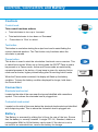
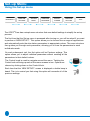
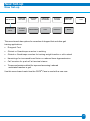
OML
Odstock Medical Ltd
Leading Rehabilitation
Through Technology
CLINICIAN’S INSTRUCTION MANUAL
Odstock® Dropped Foot Stimulator
®
Model ODFS - Pace V1.0
Software V1.2
SAFETY NOTICE:
The output of this device has
a physiological effect. Read
the instructions and
precautions before use. The
device should only be supplied
and set up by a trained clinician.
...a confident choiceTM
OML
Leading Rehabilitation
Through Technology
Salisbury
NHS Foundation Trust
Contents
2
Key features
Introduction
Important information
ODFS® Pace kit contents
3
4
6
10
Controls, Connectors and Battery
Operating Guide
Set-up menu
Finetune settings
Options menu
Activity logger
Language
Parameter View mode
Sleep mode, auto turn off and Set-up time-out
Clinical applications - Dropped Foot
Finetune - Dropped Foot
Options menu - Dropped foot
Electrode Positions - Dropped foot
The Correct Movement - Dropped Foot
Electrode Care
Footswitch
Exercise stimulation
Patient selection
Clinical Procedure - Dropped Foot
ODFS® Pace in physiotherapy gait training
New Set-up - Gluteal/Quads
New Set-up - Hamstrings
New Set-up - Calf
New Set-up - Triceps
Maintenance, servicing and fault finding
Specifications
Default Settings
References
Clinic Forms
11
12
15
18
20
22
23
24
25
26
30
34
36
40
40
42
43
46
48
49
50
52
54
55
56
57
58
60
61
Indicator light
Control knob
On / Off & level
Display
Pause button
Electrodes
plastic pin
Test button
Footswitch
metal pin
pp3
9V
Battery
Compartment
3
Key Features
Introduction
The Odstock® Dropped Foot Stimulator Pace (ODFS® Pace) is a single channel, footswitch
controlled stimulator designed to correct dropped foot in upper motor neurone conditions.
These conditions include stroke, multiple sclerosis, incomplete spinal cord injury (T12 and
above), head injury, cerebral palsy, Parkinson’s disease and hereditary spastic pararparesis.
Skin surface electrodes are placed, typically over the common peroneal nerve as it passes
over the head of the fibula and over the motor point of tibialis anterior. Stimulation produces
dorsiflexion and eversion of the foot and in certain electrode configurations produces a
withdrawal reflex, adding knee flexion and hip flexion. Electrical stimulation feels like “pins
and needles” and most people quickly become used to the sensation.
The ODFS® Pace has a comprehensive set of stimulation parameters that allow it to be
applied across a broad set of clinical presentations. While the clinician can choose any
combination of parameters, easy to use default settings can be used for most applications,
requiring only a little fine tuning for each device user.
The ODFS® Pace is also designed for more general rehabilitation use. An exercise mode
provides cyclic stimulation for muscle conditioning prior to walking or strengthening other
muscle groups. Stimulation programmes are also provided for early gait re-training of other
muscle actions such as hip extension, knee flexion and extension and push-off in terminal
stance.
The ODFS® Pace has a facility for data logging, enabling patient progress and compliance
to be monitored.
4
FES for Dropped Foot
By provision of dorsiflexion and eversion, the foot clears the ground in the swing phase of gait
more easily. This increases safety and speed and also reduces the effort of gait, reducing
compensatory mechanisms such as hip hitching and circumduction. Reduction in effort can
lead to a reduction of associated reactions and result in a general lowering of spastic tone.
Safety in weight bearing is also improved because initial floor contact is made with the heel
and then loading is along the mid line of the foot, correcting the tendency to weight bear on
the lateral border.
Contraction of the tibialis anterior muscle and the hamstrings via the withdrawal reflex may, by
reciprocal inhibition, reduce antagonist activity in the calf and quadriceps muscle groups
leading to a more normal modulation of tone. Repeated use of the stimulator may, by long
term potentiation of the required pattern of synapse activity in the spinal cord and brain, lead
to the pattern of more “normal” movement being relearned.
However, a more immediate benefit from the orthotic use of the device is that walking is
easier and safer and therefore confidence is increased, leading to an extension of mobility
range and an overall improvement in quality of life.
5
Important Information
CONTRAINDICATIONS
The ODFS® Pace should not be used on patients who have a cardiac pacemaker, implanted
defibrillator, or other electronic implanted device unless investigations demonstrate that
there is no interaction between the devices.
WARNINGS
Neck Stimulation
Stimulation should not be applied over the neck, because severe spasm of the muscles may
occur and the contractions may be strong enough to close the airway or cause difficulty in
breathing. Stimulation over the neck could also have adverse effects on heart rhythm or blood
pressure.
Open or Infected Wounds
Stimulation should not be applied over open wounds or over swollen, infected, or inflamed
areas or skin eruptions, e.g. phlebitis, thrombophlebitis, varicose veins. Stimulation should
only be applied to normal intact, clean skin.
Cancer
Stimulation should not be applied over, or in proximity to, cancerous tumours.
Electronic Monitoring Equipment
Stimulation should not be applied in the presence of electronic monitoring equipment, such as
cardiac monitors and ECG alarms. Monitoring equipment may not operate properly when the
electrical stimulation device is in use.
Transcerebral Stimulation
The effects of stimulation of the brain are unknown. Therefore, stimulation should not be
applied across the head and electrodes should not be placed on opposite sides of the head.
Sleeping
Stimulation should not be applied when sleeping.
Chest Stimulation
Stimulation should not be applied across the chest because the introduction of electrical
current into the chest may cause rhythm disturbances to the patient’s heart, which could be
fatal.
6
PRECAUTIONS
Handling Electrodes
Do not handle electrodes while the stimulation is on. Always make sure that the ODFS®
Pace is Paused before adjusting the electrodes.
Electrodes/Leads
Use this device only with the leads, electrodes, and accessories recommended by the
manufacturer. Replace leads if they become stiff or damaged in any way.
Skin Irritation
Some people may experience skin irritation due to electrical stimulation or the electrodes. The
irritation can usually be reduced by using an alternative type of electrode, different device
settings or a new electrode position. A slight reddening of the skin under the electrode is
normal and this should clear within 1 hour of stopping stimulation. If stimulation causes longterm marking of the skin, discontinue use and seek medical advice.
Skin Care
Do not shave the skin under the electrodes. If long hairs require removal, cut the hairs using
scissors. If skin moisturisers are required, use overnight and remove residual using warm
water with a mild soap before applying electrodes in the morning.
Spasticity
If stimulation causes increased spasticity (involuntary, exaggerated muscle stiffness and
spasm), discontinue use and consult your clinician.
Machinery Operation and Driving
Stimulation should not be used when driving, operating machinery, or during any activity in
which electrical stimulation could distract or put the user at risk of injury.
Bathing/Showering
Stimulation should not be applied in the bath or shower.
Shortwave Therapy
Do not use the stimulator within three metres of physiotherapy short wave therapy equipment.
Epilepsy
Patients with suspected or diagnosed epilepsy should follow precautions recommended by
their physicians. The ODFS® Pace should not be used by people who have poorly controlled
8
7
epilepsy.
Autonomic Dysreflexia
ODFS® Pace users who have high level spinal cord injuries (T6 and above), may experience
symptoms of autonomic dysreflexia (increased blood pressure or sweating in response to
stimulation). If affected, discontinue use and consult your physician.
Cardiac
Patients with suspected or diagnosed heart disease should follow the exercise precautions
recommended by their physicians.
Haemorrhage
Electrical stimulation should not be carried out in areas of the body affected by recent injury,
fracture or surgery.
Pregnancy
The safety of using electrical stimulation during pregnancy has not been established.
Children
The ODFS® Pace is not a toy! Only use as instructed by the clinician.
Latex Allergies
Caution: The Tubigrip® elastic stocking contains natural rubber latex which may cause allergic
reactions. This item is provided as an accessory to the ODFS® Pace device. Do not use if
sensitive to products that contain latex.
Long-term Effects
The long-term effects of electrical stimulation are unknown. Odstock devices have been
successfully used by individuals for excess of 14 years.
ADVERSE REACTIONS
The ODFS® Pace user should report any undesirable outcomes, malfunctioning of the device,
mistakes in using the device, or injury from the use of this device to the Clinician who
provided it to them.
The Clinician is responsible for reporting all adverse events to Odstock Medical Ltd. or their
local representative.
Attention: Device has physiological effect.
Internally powered device with applied parts of insulation type BF.
Read instructions before use
This product should not be disposed of with other houshold waste. Your
ODFS® Pace should be returned to Odstock Medical Limited for recycling.
The CE mark indicates that the ODFS® Pace complies with European Union
Medical Device Directive.
IP30 Protected against solid foreign objects of diameter 2.5mm and greater.
Odstock Medical Limited
The National Clinical FES Centre
Salisbury District Hospital,
Salisbury, Wiltshire SP2 8BJ
United Kingdom
Tel: +44 (0) 1722 429065
Fax: +44 (0) 1722 425263
www.odstockmedical.com
[email protected]
9
ODFS® Pace Kit Contents
Description
®
Part No.
Qty
®
ODFS IV
1
Electrode lead 1m*
EL-shroud 100
1
PALS neurostimulation
Platinum Blue electrodes
5cm x 5cm**
901 220
1
PP3 Battery
MN1604
1
Pair shoe insoles*
IS G10
1
Footswitch lead 1.2m*
FSL 120
1
Footswitches
FSR
2
ODFS Pace stimulator
Carry case
1
Tubigrip sleeve size G*
1
Clinicians manual
1
User manual
1
Clinicians quick start guide
1
User quick start guide
1
Kit bag
1
* Other sizes available on request
** Other electrode types and sizes available on request
10
Controls, Connectors and Battery
Controls
Control knob
This control has three actions;
•
Twist clockwise to turn up or ‘Increase’
•
Twist anticlockwise to turn down or ‘Decrease’
•
Press down to ‘Click’ or select
Test button
This button is used when testing the output level and to assist finding the
correct electrode position. The Test button only functions when the
stimulator is paused.
Pause button
This button is used to start the stimulation functional use or exercise. This
is called Active mode. When not in Active mode the ODFS® Pace is said to
be paused or in Pause mode. Active and Pause mode are switched by
repeated presses of the button. A long beep is given for entering Active
mode and a shorter, higher pitched beep given for exciting Active mode.
When the Pause mode is entered, the display will flash up the battery
condition. To keep the battery condition displayed for longer, hold down
the Pause button.
Connectors
Electrode lead socket
Located on the side of the case near the top and identified with a waveform
symbol. This is where the electrode lead is plugged into.
Footswitch lead socket
Located on the side of the case below the electrode lead socket and identified
with footprint symbol. This is where the footswitch lead is plugged into.
Battery
The Battery is accessed by sliding the lid from the rear of the box. Ensure
that the battery is correctly inserted. A single PP3 9V, Standard, alkaline or
rechargeable NiMH or NiCad battery can be used. If the device is not to
be used for an extended time, remove the battery for storage.
pp3
9V
11
Operating Guide
Turning the stimulator on
Press the Control knob and hold it down until the display comes on and
the indicator light flashes.
If the stimulator has been set to use beeps, a series of three short
beeps will accompany the light flash.
During the start up process the battery condition will be briefly
‘displayed as ‘GOOD’, ‘OK’, ‘POOR’ or ‘REPLACE BATTERY’
If the battery condition is ‘OK’ or ‘POOR’, the ODFS® Pace can still be
used but it may be necessary to increase the output level.
If ‘REPLACE BATTERY’ is displayed, the indicator light flashes and a
siren beep heard. The ODFS® Pace can still be used but the battery
should be replaced as soon as possible.
Operating Modes
After the battery condition is displayed, the Operating mode will be
shown on the top of the screen and the output level setting on the
lower part.
The 3 operating modes are:-
TEST
The stimulator will go to this mode when the footswitch is unplugged
and the clinician has not enabled the Exercise mode.
EXERCISE
The stimulator will go to this mode when the footswitch is unplugged
and if the clinician has enabled the Exercise mode.
WALK
The stimulator will go to this mode whenever the footswitch is plugged in.
When the stimulator is turned on it will start up with the output paused.
This is shown on the display by [P] once the output is set more than 1%.
12
Adjusting the Output Level (Pulse Width)
The output of the ODFS® Pace is adjusted by first clicking (press and
release) and then turning the Control knob. This sets the stimulation
pulse width. If the control lock has been deselected in the options menu
(page 21), the output can be adjusted without first clicking the control
knob. The control lock is not used in Exercise or SETUP modes.
As the knob is twisted the output level is displayed as a number from 1
to 100%.
If the stimulator has been set to use beeps, an audible click will
accompany each adjustment increment. The pitch of the click will go
up and down as the output is turned up and down.
It is good practice to only adjust the output while there is a stimulation
output. This enables an instant feedback of the effect of the change.
Using the Test button
While the stimulator is paused, the output can be tested by pressing
the Test button. There is no need to click the Control knob before
adjusting when the test button is used.
The indicator light will flash and if the stimulator has been set to use
beeps, a chirp will accompany the light flash.
While there is an output from the device the level indicator (pulse
width) appears as a row of blocks on the lower line
The level displayed follows the output as it ramps up and down.
The light flashes in sequence with the stimulation.
The stimulation will time-out and stop or can be stopped at any time by
pressing the Test button again or pressing the Pause button.
Please note. In Test, Walk and Exercise mode, a stimulus is produced
when the Test button is pressed down. In Set-up mode, the Test button
follows the setting of the footswitch. This means if the device is set to
heel rise, a stimulus is produced when the button is pressed and then
released. In Heel Strike mode, a stimulus is produced when the button
is pressed. Any set parameters (ramps, extensions, frequency etc) will
also be shown.
13
Using the Pause button
When the stimulator is set for Walk or Exercise the Pause button is
used to start and stop the operation of device.
Press the Pause button to start operation
The indicator light will flash and if the stimulator has been set to use
beeps, a long beep will accompany the light flash.
The level indicator will be shown on the display.
If the footswitch is plugged in the screen will display ‘WALK’ and the
ODFS® Pace will respond to the footswitch.
If the footswitch is not plugged in and the exercise function has
previously been turned on, the screen will display ‘EXERCISE’ and
stimulation will immediately begin.
If the footswitch is plugged in while the exercise sequence is running
the ODFS® Pace will enter Walk mode and will be paused. Press the
Pause button to start walking.
If the exercise function has not been turned on and there is no
footswitch plugged in, pressing Pause will cause a long bleep followed
by two short and lower pitch bleeps. The display will flash ‘NO FOOT
SWITCH!’
To stop operation, press the Pause button again. A shorter higher pitch
beep is heard.
14
Turning the Stimulator Off
The stimulator can only be turned off when the output has been paused.
This is to prevent the device being accidently turned off while walking.
Check to see if the ‘[P]’ symbol is displayed, if not pause the stimulator.
Rotate the Control knob anti-clockwise until the output on the display
reads 1% and the 1/0 appears. If the BEEPS ON+ option is set (Options
page 20) a beep is heard when 1% is reached.
Then press and hold down the Control knob to turn the device off.
If the stimulator has been set to use beeps the light flashes will be
accompanied by two long beeps.
When the ODFS® Pace is turned off, the pulse width setting is reduced
to 1%. The user must reset the level to begin use of the device again.
The purpose of this feature is to ensure that ODFS® Pace users who
turn the device up throughout the day as their muscles become tired do
not receive an unexpectedly high level of stimulation when they turn the
device on the next day. The ODFS® Pace should therefore not be
turned off using the Control knob throughout the day but put into Sleep
mode using the Pause button.
Accessing the Set-up menu
When the stimulator has been turned on and is paused the Set-up
menu can be used.
All of the parameters necessary for setting up the stimulator are
contained within the Set-up menu. To prevent these settings
from being inadvertently adjusted, the Set-up menu is under
normal circumstances not accessible by the patient.
+
To access this menu:1. Click and hold down the Control knob.
2. While continuing to hold down the Control knob
press the together the Test and Pause buttons.
3. Release the Test and Pause buttons.
NEW
SETUP?
4. Release the Control knob and the first screen of the Set-up
menu will be displayed.
15
Set-up Menu
Using the Set-up menu
NEW SETUP?
FINETUNE
SETTINGS
OPTIONS
MENU
EXERCISE
PROGRAMS
ACTIVITY
LOGGER
LANGUAGE
OPTIONS
...EXIT
The ODFS® Pace has a simple menu structure that uses default settings to simplify the set-up
process.
The first time that the Set-up menu is accessed after turning on, you will be asked if you want
to perform a ‘NEW SETUP?’. This option allows you to choose from a range of applications
and automatically sets the stimulation parameters to appropriate values. The menu structure
then guides you through each parameter, allowing you to tune the parameters to each
individuals needs.
On each subsequent visit, the first option will be Finetune settings. This
option allows you to adjust individual parameters without resetting all the
parameters to their default values.
The Control knob is used to navigate around the menu. Twisting the
Control knob will bring up each of the menu screens in turn. Options are
chosen by clicking down on the Control Knob.
Each time that the ‘NEW SETUP?’ screen is displayed a double beep is
heard. This is to remind you that using this option will overwrite all of the
previous settings.
16
New Set-up
New Set-up
NEW SETUP?
DROPPED
FOOT
FINETUNE
SETTINGS
OPTIONS
MENU
EXERCISE
PROGRAMS
ACTIVITY
LOGGER
LANGUAGE
OPTIONS
GLUTEAL/
QUADS
HAMSTRINGS
CALF
TRICEPTS
...BACK
...EXIT
This menu branch has options for correction of dropped foot and other gait
training applications.
•
Dropped Foot
•
Gluteal or Quadriceps muscles in walking
•
Gluteal or Quadriceps muscles for training weight transfer or sit-to-stand
•
Hamstrings for increased knee flexion or reduced knee hyperextension
•
Calf muscles for push-off at terminal stance
•
Triceps and posterior deltoid for improved arm swing / reduced
associated reaction in gait.
Use this menu branch each time the ODFS® Pace is used with a new user.
17
Finetune Settings
Using Finetune Settings
NEW SETUP?
FINETUNE
SETTINGS
OPTIONS
MENU
EXERCISE
PROGRAMS
ACTIVITY
LOGGER
LANGUAGE
OPTIONS
...EXIT
PULSE WIDTH
OUTPUT
CURRENT
RISING RAMP
EXTENSION
TIME
FALLING
RAMP
1 - 100%
10 - 100mA
0 - 2s
0 - 2s
0 - 2s
Once you have chosen the application you need from ‘NEW SETUP?’ screen, the next
menu item to appear on the screen is ‘CURRENT’. Current is the first parameter on the
Finetune menu. This parameter sets the contraction strength and it needs to be set for each
individual ODFS® Pace user (see page 27)
The Finetune menu allows adjustment of all the parameters that make up the
applications used in the New Set-up menu.
Each item of the Finetune menu will be described in the Clinical Application section of this
manual (page 27-33)
18
TIME OUT
PERIOD
0 - 6s
STARTING
DELAY
0 - 2s
OUTPUT
WAVEFORM
ASSYMETRICAL
SYMETRICAL
OUTPUT
FREQUENCY
EXIT
20 - 60Hz
19
Options menu
NEW SETUP?
FINETUNE
SETTINGS
OUTPUT
SOUNDER
NO SOUNDER
BEEPS OFF
BEEPS
SETUP ONLY
BEEPS ON
OPTIONS
MENU
EXERCISE
PROGRAMS
FOOT
SWITCH
ACTIVITY
LOGGER
BEEPS ON+
...EXIT
CONTROL
LOCK
...EXIT
LOCK OFF
LOCK 1s
LOCK 3s
ADAPTIVE
TIMING
FIXED TIMING
TIMING MODE
ALWAYS ON
LANGUAGE
OPTIONS
HEEL RISE
NO TIME OUT
HEEL STRIKE
Options Menu
This menu allows adjustment of less frequently changed settings. The currently set option is
indicated by a black square. When an option is selected by clicking the Control knob, the
Options menu is exited and the ODFS® Pace returns to the main Set-up menu.
Output Sounder
This is the audible feedback that accompanies the stimulation. This is used to check the
timing of the stimulation while watching the ODFS® Pace user walk. There are three options:
•
•
‘NO SOUNDER’ - the sounder will be turned off in all modes.
‘SETUP ONLY’ - The sounder will work while adjustments are being made in ‘SETUP ONLY’.
•
‘ALWAYS ON’ - the sounder will work at all times.
The Default is ‘SETUP ONLY’.
Beeps
This option allows you to turn on or turn off the beeps.
There are three options:
·
·
·
‘BEEPS OFF’
‘BEEPS ON’
‘BEEPS ON+’
20
BEEPS
The ‘BEEPS ON+’ adds a high tone beep when he 50% level is reached and a low double
beep when 1% is reached. This informs the users who may not be able to watch the display,
when the output is at the normal operation level (50%) and when they can click the Control
knob to switch the device off (1%).
The Default is ‘BEEPS ON’.
Footswitch
This option allows you to choose if stimulation is triggered when weight is
placed on (heel strike) or taken off (heel rise) the footswitch. For a full
description and clinical application of this parameter please see page 33.
Timing Mode
This option sets the timing action of the foot switch.
•
In ‘ADAPTIVE TIMING’ stimulation is started and stopped by the
footswitch up to a maximum time set by the ‘TIME OUT PERIOD’
(Finetune menu).
•
In the ‘FIXED TIMING’ mode stimulation starts with a footswitch but
continues for as long as the time set by the ‘TIME OUT PERIOD’
(Finetune menu).
In ‘NO TIME OUT’ (NTO) stimulation is started and stopped by the
footswitch but there is no maximum time.
•
FOOT
SWITCH
TIMING
MODE
For a full description and clinical application of this parameter please see
page 35.
Control Lock
CONTROL
LOCK
The control lock is intended to stop accidental adjustment of the output in
User Mode. There are three options:
·
·
·
‘LOCK OFF’ - The pulse width can be turned up and down without
clicking the Control knob. Choose this option if the user finds clicking
before adjusting difficult.
‘LOCK 1s’ - The Control knob must be clicked before adjusting.
The adjustment must start within one second of the click.
‘LOCK 3s’ - The Control knob must be clicked before adjusting.
The adjustment must start within three seconds of the click.
The Default setting is ‘LOCK 3s’.
Exit
Use this option to save settings and leave the menu.
21
Activity Logger
PRESS TO
NEW SETUP?
STEPS
FINETUNE
SETTINGS
NO. WALKS
OPTIONS
MENU
WALK h:m
EXERCISE
PROGRAMS
LANGUAGE
OPTIONS
ACTIVITY
LOGGER
NO. EXE
EXE. H:M
...EXIT
RESET
CONFIRM
Using the Activity Logger
After opening the Set-up menu navigate to the Activity logger screen and click the Control knob.
Use the Control knob to navigate around the sub menu and read off the stored log data.
‘STEPS’
Records the total number of footsteps (affected side only) since the logger
was last reset.
‘No. WALKS’
Records the number of times that stimulation was started for walking since
the logger was last reset.
‘WALK h:m’
Records the total time in hours and minutes that the stimulator has spent
stimulating in walk mode (i.e. swing time only) since the logger was last
reset.
‘No. EXE’
STEPS
14404
No. WALK
42
WALK h:m
3:18
Records the total time in hours and minutes that the stimulator has been
used for exercise since the logger was last reset.
‘EXE. h:m’
No.EXE.
3
Records the total time in hours and minutes that the stimulator has been
used for exercise since the logger was last reset.
‘RESET?’
EXE.h:m
1:20
Clears the logger and resets all values to zero. Confirmation is required
before this can happen.
Note: If you access the ‘PRESS TO CONFIRM’ screen unintentionally then
you can escape without resetting the logger, by twisting the Control knob.
RESET?
PRESS TO
CONFIRM
22
Language
NEW SETUP?
FINETUNE
SETTINGS
OPTIONS
MENU
EXERCISE
PROGRAMS
ACTIVITY
LOGGER
ENGLISH
LANGUAGE
OPTIONS
...EXIT
OTHER
Using Language Options
After opening the Set-up menu navigate to the Language options screen and click the Control
knob.
Scroll through the language options using the Control knob and click on your chosen option.
23
Parameter View mode
This facility allows all the parameter and activity logger values to be viewed
without going into Set-up mode. This is used to copy down the device
settings at the end of a clinic session for record keeping. See Clinical
Settings Form at the end of this manual. It is not possible to adjust
parameters in this mode.
+
With the device turned off, press and hold down the Test button and then
press and hold down the Control knob. The display will now show the first
screen, which is the basic walking set-up. This uses the codes listed below.
DF - Dropped foot
GQ- Gluteal / Quadriceps
H - Hamstring
C - Calf
T - Triceps
KF - Knee flexion
HE - Hyper extension
HS - Heel strike
HR- Heel rise
NTO - No Time-Out
Navigate by twisting the Control knob to go backwards or forward. Press
Pause to exit Parameter view mode, or press and hold the Control knob to
turn off.
24
SET UP
DF HR
Sleep Mode
Sleep
If the ODFS® Pace is left paused for longer than 10 minutes it will
automatically go into a power saving sleep state.
As the ODFS® Pace enters sleep it will flash the indicator light. The light will
then flash every 5 seconds to show that it is asleep.
5s
The ODFS® Pace can be woken from sleep by clicking the Control knob, or
pressing the Pause button.
If the ODFS® Pace is woken by clicking the Control knob it will awake
paused.
If the ODFS® Pace is woken by pressing the Pause button it will enter its
Active mode and stimulation will be enabled. If a footswitch is plugged in the
stimulator will be ready to walk.
Auto turn off
After remaining in Sleep mode for 4 hours the stimulator will turn off
automatically.
Note. The pulse width is reduced to 1% when the device turns off and will
need to be reset by the user before walking.
Set-up time-out
If the ODFS® Pace is left in the Set-up menu (but not in Active mode) for
longer than 10 minutes without any adjustments being made, it will
automatically exit Set-up mode and return to the User mode (paused).
If, while in Set-up, the ODFS® Pace is left in Active mode (i.e. the user is
walking with the ODFS® Pace) for more than 10 minutes, the next time that
the Pause button is pressed to stop walking, the ODFS® Pace will exit Set-up
and go to the User mode.
25
Clinical Applications - Dropped foot
Turn the device on by pressing the Control knob down for 1 second
Put the device into Set-up mode by again pressing and holding down
the Control knob and then pressing the Test and Pause buttons together,
then letting all three buttons go.
Tip: This is sometimes easier to do if the output is set higher than 1%,
stopping the ODFS® Pace being accidently turned off.
A double beep is heard and the screen display will read ‘NEW SETUP?’.
If you wish to set the device up for a new user or a new application with
the same user, choose this option by pressing the Control knob. This
will reset all the parameters to default values including setting the
current to its minimum.
If you wish to make adjustments to an existing set-up, rotate the Control
knob clockwise one step to the Finetune screen. This option allows
adjustment of individual parameters without resetting all of them.
Select ‘NEW SETUP?’. The next screen allows you to chose a
treatment type. Choose ‘DROPPED FOOT’ by clicking the Control
knob.
The next screen lets you choose how the ODFS® Pace is controlled by
its footswitch. For dropped foot the most common way is to use’ HEEL
RISE’. In this mode the footswitch is placed under the heel on the
affected side. Stimulation will start when weight is taken from the foot
switch. Select this option.
26
+
NEW
SETUP?
FINETUNE
DROPPED
FOOT
HEEL
RISE
Dropped foot - Setting the current
The menu screen will briefly display ‘CURRENT TEST’ and then go to
current setting screen.
The display shows the output current already set. The minimum current
setting is 10mA (milliamps).
CURRENT
TEST
10.0mA
The current is set with a pulse width of 180μs (micro seconds), which is
half the pulse width range (50%). This is to allow the ODFS® Pace user
to increase the contraction strength by increasing the pulse width,
compensating for day to day variations in muscle fatigue, electrode
position and battery condition or changes in muscle tone.
While the patient is sitting with their leg in a relaxed, near extended
position, place the electrodes as shown below.
27
Dropped foot - Setting the current
To test the current output, press and release the Test button. The LED
will flicker to indicate an output and an audio signal is given. A bar
graph will appear on the bottom line of the display and indicates the
pulse width of the stimulation. The bar graph will change, indicating the
rising and falling ramps.
While stimulating, increase the current by rotating the Control knob
clockwise. Observe the effect on the patient. You will need to
repeatedly press and release the Test button to find the correct setting.
The current can only be increased while stimulating, but can be reduced
between test stimulations.
The correct movement is dorsiflexion with a small amount of eversion. If
the correct movement is not produced, refer to the section on electrode
positions (pages 36-39)
Once a good movement is produced, connect the footswitch to try
walking. Press the Pause button to enter Active mode. A long beep is
heard. The patient can then walk with the device.
It is often the case that the level of stimulation needs adjusting when the
ODFS® Pace user is walking. This can be because the level of calf tone
is different when upright or you may have wrongly estimated the amount
of dorsiflexion required for walking. Unlike when using the Test button,
the current can be increased between steps.
If the ODFS® Pace user is walking well, then you have completed the
set-up procedure! The Set-up mode can be exited and the ODFS® Pace
issued.
28
Exiting Set-up and Pulse Width
adjustment
Exiting Set-up mode
Press the Pause button to leave Active mode
Press the Control knob to go out of the current setting screen.
Rotate the Control knob until the Exit screen is reached.
...EXIT
Press the Control knob again to exit the Set-up mode.
Changing the Pulse Width setting in Finetune
It is normal to leave the pulse width set to its default of 50% (180µs).
However sometimes it is useful to set a different pulse width:
•
If a strong contraction is produced at 10mA, reduce the pulse width
•
If an insufficient contraction is produced at 100mA, increase the
pulse width
•
Sometimes a larger or smaller pulse width may be more comfortable
PULSE
WIDTH
50%
If the pulse width is increased, reduce the current before testing.
NB. When testing the output while in ‘PULSE WIDTH” it is the current
that is adjusted while stimulating.
PULSE
WIDTH (!)
Pulse width out of range warning
If you enter FINETUNE with a pulse width setting Outside the normal
operating range (45-55%) the PULSE WIDTH (!) warning is given. If the
pulse width is at the intended setting, ignore this warning by rotating the
Control knob to access the rest of the FINETUNE menu. If the pulse
width is correct, click the Control knob to enter the pulse width setting
screen. Set the pulse width to 50% or other intended level.
(!) 1%
29
Finetune - Dropped foot
Rising Ramp
While the default setting will be suitable for many people, often some
adjustments are required to achieve the best result.
Press the Pause button to exit Active mode and press the Control knob
to leave the current setting screen.
The next screen you come to is ‘RISING RAMP’. This parameter allows
you to choose how fast the stimulation rises to its maximum pulse width
once a stimulation output starts. There are 3 reasons why you might
adjust this parameter.
•
In people who have spasticity in their calf muscles, a rapid rise in
pulse width will cause a rapid stretch of the calf that may result in a
stretch reflex. This reflex will oppose dorsiflexion and may appear as
a general stiffening of the calf or clonus spasm. A longer ramp
helps to prevent this happening.
•
Some people find a rapid rise of pulse width uncomfortable. A longer
ramp may be more acceptable.
•
If dorsiflexion occurs too soon, it is difficult for the patient to use their
calf muscles to push forward at terminal stance. A longer ramp
may allow this to happen.
However, in all cases it is important that the stimulation ramps fast
enough to cause dorsiflexion when the foot is lifted. For this reason,
faster walkers will require shorter ramps.
Click to select. The rising edge ramp can be adjusted from 0 to 2000ms.
Turn the Control knob clockwise to increase the ramp time. The default
for dropped foot is 200ms
30
RISING
RAMP
200ms
Finetune - Dropped foot
Extension
Extension allows you to add a period of stimulation after weight is returned
to the heel switch (or taken off it in Heel Rise mode). This enables an
eccentric contraction in the anterior tibialis, lowering the foot to the ground.
If the extension is too short, the ankle will lack control at the weight
acceptance phase of gait. An audible slap may be heard as the foot
strikes the ground
EXTENSION
TIME
Extension can also be used to provide eversion for ankle stability in initial
weight bearing when there is excessive inversion.
Do not use excessively long extensions as this reduces the period between
muscle contractions increasing muscle fatigue
Use the sounder to set the Extension so that the stimulation ends at the
point the foot is flat on the ground. Extension can be adjusted from 0 to
2000ms. The default for dropped foot is 200ms
200ms
Falling Ramp
The Falling Ramp is the length of time the pulse width takes to reach zero
after the Extension has ended. It can be used with the Extension to control
the movement of the foot after heel strike and increase comfort. It can be
adjusted between 0 and 2000ms. The default for dropped foot is 150ms.
FALLING
RAMP
150ms
Envelope
Pulse width
Rising
Ramp
Heel Rise
Extension
Time out period
Falling
Ramp
Heel Strike
31
Finetune - Dropped foot
Time-Out Period
The Time-Out Period is the maximum time that stimulation can last for from
a single footswitch or test switch trigger. It should be set just a little bit
longer than the longest stride time taken by the user. Ensure this is long
enough for activities such as stair climbing. For comfort, do not set the
Time-Out Period too long as this means the user will get a long stimulation
when they take weight off the switch when sitting down. The Time-Out
Period can be adjusted between 300ms and 6000ms (6 seconds)
TIME OUT
PERIOD
2500ms
Starting Delay
The Starting Delay allows the stimulation to begin a little time after the
footswitch change. This allows a muscle contraction at a time other than
when weight is placed on or removed from the footswitch. This parameter
is not normally used in Dropped Foot Correction. The delay can be
adjusted between 0 and 2000ms. Leave at 0ms for dropped foot.
STARTING
DELAY
00ms
Output Waveform
The ODFS® Pace has a choice of 2 waveforms, Asymmetrical biphasic ’ASYM’ and
Symmetrical biphasic ‘SYM’. The set waveform is marked with a black square.
When the Asymmetrical biphasic waveform is used, the strongest stimulation effect is under
the Active electrode (black electrode plug). This can be useful in creating stimulation effects.
For example, placing the Active electrode over the common peroneal nerve and Indifferent
electrode over the anterior tibialis will generally produce dorsiflexion with eversion. Swapping
the electrodes around will give more dorsiflexion and less eversion. (See pages 37 and 38)
In Symmetrical biphasic, the polarity of every other pulse is reversed. This means both
electrodes have equal stimulation effect. For some people this will produce a better balance
of eversion and inversion. Some people find this waveform more comfortable.
SYM.
ASYM.
32
SYM.
ASYM.
Output Waveform - Skin Irritation
In the case of people who have sensitive skin, Symmetrical biphasic is less
likely to produce a skin irritation in reaction to the electrodes.
If a skin irritation occurs after using Asymmetrical biphasic, allow the skin
to heal, and then change to Symmetrical biphasic to prevent
reoccurrence.
Frequency
Frequency is the number of pulses per second measured in Hertz (Hz).
The standard frequency for dropped foot stimulation is 40Hz.
A lower frequency can be used to reduce fatigue in the stimulated muscles.
Increasing the frequency will tend to produce a brisker reaction and may
produce a greater withdrawal reflex (a reflex consisting of hip, knee and
ankle flexion).
OUTPUT
WAVEFORM
SYM.
ASYM.
OUTPUT
FREQ.
40Hz
Increasing the frequency has been particularly useful for some people who
have MS who do not get a good response at 40Hz. However, using higher frequencies can
increase muscle fatigue. Frequency is adjustable from 20 to 60Hz in 5Hz steps.
Testing and Walking in FINETUNE
The ODFS® Pace parameters can be tested and the output current adjusted at any point in
the Finetune menu. Only the Current can be adjusted while testing or walking.
If you have a parameter selected, the screen will change to ‘CURRENT’
when either Pause or Test buttons are pressed.
If the ODFS® Pace is in the upper part of the Finetune menu (i.e. not
adjusting a parameter) then:
• If the test button is pressed, an output will be given and the screen
will have the test symbol [.]
• If the Pause button is pressed, the foot switch can be used. The
screen will display [ > ].
33
Options Menu - Footswitch
Footswitch
The Footswitch menu allows you to choose if the stimulator is triggered
on heel rise (when weight is taken off the switch) or heel strike (when
weight is put back on the switch).
For dropped foot correction, heel rise is more commonly used. The
switch is placed under the heel of the affected side. This means all the
equipment is on the same side of the body. This is considered more
convenient by most people.
However, if foot contact is unreliable on the affected side, it can be more
effective to place the footswitch under the heel on the opposite side.
This can give a more reliable trigger but now the stimulation needs to
begin when weight is put on to the switch so the heel strike setting is
used. Some faster walkers also prefer this mode.
OPTIONS
MENU
FOOT
SWITCH
HEEL
RISE
HEEL
STRIKE
In Heel Rise mode users should take their first step each time with their
non-affected leg.
If this mode is chosen from the Option menu, all other parameters will be left unchanged.
When the ‘HEEL RISE’ / ‘HEEL STRIKE’ option is chosen in the ‘NEW SETUP?’ menu, all
parameters are set to defaults.
34
Options Menu - Timing Mode
Timing Mode
The ODFS® Pace has three timing modes.
Adaptive Timing: In this mode stimulation is started by a footswitch
change (e.g. heel rise or heel strike) and ended by a footswitch change
(e.g. heel strike or heel rise). If the second footswitch change does not
occur before the set Time-Out Period, stimulation will end automatically.
This Timing mode adapts well to walking speed changes and is used in
most default settings including dropped foot.
Fixed Time: In this mode stimulation starts on a footswitch change (e.g.
heel rise or heel strike) but is ended after a fixed time set by the TimeOut Period. This mode is used when foot contact is inconsistent and
gives unreliable triggering. It can be useful if the ODFS® Pace user is
hesitant in taking steps, taking weight on and off the footswitch as
multiple attempts are made.
OPTIONS
MENU
TIMING
MODE
ADAPTIVE
TIMING
FIXED
TIMING
Carefully adjust the Time-Out Period by listening to the sounder and
watching the response to stimulation. Stimulation should end at the point
the foot returns to being flat on the ground after heel strike.
No Time-Out: This mode is similar to Adaptive Timing except there is no
maximum time for stimulation output. The output simply follows the
footswitch. An Extension is still added to the end of the stimulation
output. This mode is not normally used in dropped foot correction but
used for stimulating anti gravity muscles such as Quadriceps or Gluteus
Maximus.
NO TIME
OUT
35
Electrode Positions - Dropped foot
Dorsiflexion is produced by stimulation of the common peroneal nerve and / or its branches.
By choosing the position of the electrodes it is possible to tailor the response to suit each
individual. Generally, the common peroneal is stimulated where it is most superficial, either
where it passes the head of fibula or in the popliteal fossa. Electrodes can also be placed
over the point where the nerves enter the muscles, typically over the motor point of tibialis
anterior.
Electrodes and Waveform
The following descriptions of electrode placements assume 50 x 50 mm PALS® electrodes.
An Asymmetrical waveform is assumed unless otherwise stated.
36
Electrode Positions Dropped foot
Electrode Position 1 (standard)
The Active electrode (black electrode plug) is
placed with its top edge on the head of fibula.
Imagine the electrode divided into quarters. The top
front quarter is on the head of fibula, the bottom front
corner is below the head, the top back quarter is
behind the head and the bottom back quarter is
below and behind the head. The Indifferent electrode
is placed over the Anterior Tibialis. Avoid placing the
Indifferent electrode over the Tibia bone as this will
cause the stimulation to sting.
If there is too much eversion produced, move the Active
electrode forwards. If too much inversion is
produced, move the Active electrode backwards and
upwards.
This is the most commonly used position and is
usually the easiest for the patient to use
independently.
Electrode Position 2 (reversed polarity)
If too much eversion is produced by the standard
electrode postion, reverse the polarity of the electrodes,
placing the Active electrode (black electrode plug) on
the motor point of Anterior Tibialis and Indifferent
electrode (red electrode plug) on the head of fibula. It
is common with this electrode position to require a
slightly higher stimulation intensity. The electrode on
the head of fibula can be adjusted in the same way as
position 1 to modify the response.
If this position produces too much inversion, change the
Output Waveform to Symmetrical biphasic. This will
give an equal stimulation effect on both electrodes,
producing more eversion than Position 2 and less
than the standard position.
37
Electrode Positions - Dropped foot
Electrode position 3 (Popliteal fossa)
If a stronger response is required, place one of the electrodes on the lateral border of the
Popliteal Fossa. Place the outer edge of the electrode along the biceps femoris tendon. Do
not place the electrode too medially as this may recruit the Tibial Nerve, causing calf activity.
This position can increase knee flexion by recruiting the withdrawal reflex. This reflex
consists of hip, knee and ankle flexion together with ankle eversion and hip external
rotation.
The strongest effect is with the Active electrode in the Popliteal Fossa. If this produces too
much eversion, place the Indifferent electrode on the Popliteal Fossa. Alternatively, a
withdrawal reflex with a stronger element of dorsiflexion and less eversion can be achieved by
placing one electrode on the motor point of Anterior Tibialis and the other in the Popliteal
Fossa.
With all these positions, change the waveform to Symmetrical biphasic to modify the
38
Electrode Positions - Dropped foot
response further.
Position 4 (motor point stimulation)
If the other three positions all produce too much eversion, stimulate the motor point of Anterior
Tibialis directly by placing the Active electrode on the motor point and the Indifferent electrode
more distally. This position generally requires greater stimulation intensity so can be less
comfortable than stimulation of the common peroneal nerve. If too much inversion is
produced, move either or both electrodes laterally towards the peroneus longus and brevis.
Occasionally, ODFS® Pace users may experience toe clawing (flexion) while walking.
Greater toe extension may be achieved in positions 1 and 4 by placing the Indifferent
electrode more distally, over the toe extensor motor points.
39
The correct movement - Dropped foot
The aim is to produce as natural movement as possible. Stimulation produces dorsiflexion
and eversion as the foot leaves the ground, leaving sufficient time for push off using voluntary
calf activity if it is present. The foot clears the ground with sufficient clearance to prevent the
toe from catching the ground. Stimulation enables heel strike, and maintains control of the
ankle as the foot is lowered to the ground, preventing foot slap. Because heel strike occurs
with a degree of eversion, weight is borne through the mid line of the foot, stabilising the ankle
through stance phase.
Electrode Care
Odstock Medical recommend the use of PALS® Platinum Blue 50mm x 50mm #901220 self
adhesive electrodes or equivalent for dropped foot correction. These electrodes have proved
to be the most reliable in clinical practice, are the easiest to use and the least likely to cause
skin irritation. An alternative electrode type is the PALS® Plus range, available in a variety of
sizes suitable for other applications as well as dropped foot. ODFS® Pace users with smaller
legs will require smaller electrodes.
Whichever type of electrodes are used, it is very important that both the skin and electrodes
are kept clean. This will help prevent a skin reaction developing. If skin is very dry, or if
moisturiser has been used, wash the skin with warm water and dry it before placing the
electrodes on the skin. If moisturisers are required, use water based products such as E45
cream and apply at night before going to bed. Do not place electrodes over broken skin or a
rash of any kind. Do not shave the skin as this will cause many tiny abrasions. If long hairs
prevent reliable skin adhesion, trim the hairs with scissors. All electrodes are for single
40
patient use. An elastic cuff (Tubigrip®) can be used to hold the electrodes in place.
Electrode Care
1. Connect the electrodes to the leads by sliding the pin into the connector on the electrodes
leads. Ensure that the pin is inserted fully and that no metal is visible.
2. Peel the electrode away from the plastic backing by lifting at the electrodes edge. Do
not pull the electrodes lead.
3. Place the electrodes on the skin as described in the electrode placement section. Care
should be taken when putting on clothing over the electrodes and wires.
4. After use, ensure that the ODFS® Pace is turned off before removing the electrodes.
Peel the electrode away from the skin by lifting it at the edge. Do not pull the lead. Return the
electrodes to the plastic backing and remove the electrode lead by pulling the plug from the
lead connector. Do not pull on the electrode lead. Store the electrodes in the packaging
provided. Alternatively leave the leads connected and store the leads with the electrodes.
5. After repeated use the electrodes lose their stickiness. To make them sticky again,
dampen the surface of the electrodes with water by running two fingers under a tap then
wiping across the electrode a couple of times and then leave for a few minutes to dry. This
rehydrates the electrode and also removes any debris from the surface. If this is not successful,
replace the electrodes. Electrodes should last about four weeks. Replacing electrodes regularly
helps to prevent skin irritation.
When the electrodes positions have been found, it is very important to teach the ODFS® Pace
user how to find the positions for themselves. Key to this is
teaching how to find the head of the fibula bone. One technique is to teach the ODFS® Pace user to
place a finger on the lateral malleolus at the ankle then move the finger up the
outside of the leg until the next bony prominence is found, which
will be the head of fibula. Make sure there is no confusion with
lateral condyle on the tibia bone.
It is often useful to draw on the back of the electrode that is on
the head of the fibula, the outline of the head. This enables the
electrode to be easily lined up with the anatomical landmark.
Providing a photograph of the electrode positions is also
beneficial. Also mark in the user instruction manual and quick
start guide the position of the electrodes. Finally, some ODFS®
Pace users choose to draw around the electrodes with a skin
marker. Use colour coding to identify the polarity of the
electrodes.
41
Footswitch
The footswitch is fixed on the underside of a cork insole. Remove the wax-paper backing
from the adhesive tape on the black side of footswitch and place on the insole. The lead
passes forward in the shoe and exits under the medial arch of the foot. If stimulation is
required slightly later in the gait cycle, place the footswitch further forward on the insole.
Avoid placing the switch further forward than the metatarsal heads to maintain reliable
triggering.
If the user tends to weight bear on either the lateral or medial side of the foot, move the switch
to that side of the insole to improve reliability.
Placing the footswitch on an insole enables the switch to be easily moved from shoe to shoe.
It is also possible to stick the switch to the sole of the foot, running the cable under socks,
stockings or tights.
42
Exercise stimulation
At the initial assessment the ODFS® Pace is tried and in most cases an improvement in gait is
immediately apparent. In some cases a period of electrical stimulation training is useful
before using the ODFS® Pace for walking. This is done using the ODFS® Pace Exercise
mode This may be indicated for the following reasons:
•
To strengthen muscles. Regular exercise with electrical stimulation will increase muscle
bulk leading to increased strength and fatigue resistance. Electrical stimulation
exercises can be used for many of the affected muscles.
•
To reduce spasticity and increase ankle range of movement. Regular stretching of the calf
muscles using common peroneal stimulation may lengthen the muscle and tendons. It is
thought the Common Peroneal Nerve stimulation will also, via reciprocal inhibition, reduce
calf over activity and if repeated may lead to extended periods of reduced calf tone.
•
To accustom the patient to the sensation of electrical stimulation. If a candidate for the
ODFS® Pace is sensitive to the sensation of the stimulation, tolerance to the sensation
can be built up over time by exercising each day, gradually increasing the level of
stimulation day by day till a sufficient contraction is produced.
•
To reduce oedema. In some cases, excessive oedema may reduce the range of ankle
mobility. Daily exercise stimulation may, by the venous pump action of the calf
compartment, reduce fluid pooling in the foot and lower leg.
•
To allow the user to become accustomed to placing the electrodes.
Commonly, exercise is started with relatively short periods, for example twice a day for 10
minutes and gradually increased over a period of several weeks as strength and fatigue
resistance improves to up to two periods of 30 minutes.
43
Exercise Stimulation
Stimulation intensity (pulse width) in the exercise mode
NEW SETUP?
FINETUNE
SETTINGS
OPTIONS
MENU
EXERCISE
PROGRAMS
ACTIVITY
LOGGER
LANGUAGE
OPTIONS
...EXIT
ENABLE
EXERCISE
EXERCISE
DURATION
ON
PERIOD
OFF
PERIOD
RAMP
DURATION
EXIT
EXERCISE
ON
EXERCISE
OFF
5-100 min NO LIMIT
1-10
seconds
1-10
seconds
1-10
seconds
REPEATS FOR EXERCISE DURATION
RAMP
ON PERIOD
RAMP
OFF
PERIOD
RAMP
ON PERIOD
RAMP
Using the Exercise mode
After opening the Set-up menu navigate to the Exercise screen and click the Control knob.
Navigate through each of the menu options clicking on them to change or check the settings.
Note. Exercise mode uses the same stimulation parameters (current, frequency and
waveform) that are set in the current Finetune / New Set-up menus.
Once exercise is enabled, the user selects exercise mode by unplugging the
footswitch jack plug from the ODFS Pace. The screen will change from
‘WALK’ to ‘EXERCISE’. Press the Pause button to start and stop exercise.
44
Enable Exercise
Use this option to enable the exercise programme. If the Exercise mode is not required by
the user, it is good practice to disable the Exercise mode. This will prevent device users from
using the Exercise mode to walk. (Disabled is the default option).
Exercise Duration
You can choose the maximum time for exercise in a range 5 to 100 minutes in 5 minute
steps. If the exercise duration is increased past 100 minutes, the screen changes to
indicating
that there is no limit to the exercise duration.
Once the user has completed the full exercise duration, the exercise can not be restarted
again unless the ODFS Pace is turned off then on again.
On Period
The stimulation can be set to remain on for a period from 1 to10 seconds between ramping
up and ramping down.
Off Period
The stimulation can be set to stay off for a period from 1 to 10 seconds between ramping
down and ramping up again. The Off Period allows time for blood circulation to return to the
muscle, replenishing oxygen and removing metabolic waste. If the Off Period is too short,
muscle fatigue may result. The Off Period is normally not set shorter than the on period.
Ramp Duration
For the exercise mode the rising ramp and the falling ramp share the same timing. The ramp
duration can be set from 1 to 10 seconds. If the person has spasticity, choose a ramp of 2
seconds or more to avoid eliciting a stretch reflex. If the person experiences clonus in response
to stimulation, lengthen the ramp until the clonus is eliminated. People who find stimulation
uncomfortable will find longer ramps more comfortable.
Testing in Exercise
The set exercise parameters can be tested while in the upper part of the
exercise menu (EXERCISE DURATION, ON PERIOD, OFF PERIOD,
RAMP DURATION). Disconnect the foot switch jack plug and press the
Pause button to begin the exercise sequence. The pulse width can be adjusted while testing.
Exit
Use this option to save settings and leave the menu.
45
Patient selection - Dropped foot
Use of ODFS® Pace as an Orthosis
Cause and Functional Deficit
•
Neurological deficit due to an upper motor neurone lesion. An upper motor neurone lesion
is defined as one that occurs in the brain or spinal cord at or above the level of T12. This
is often but not exclusively associated with spasticity.
•
Upper motor neurone lesions resulting in dropped foot occur in conditions such as stroke,
multiple sclerosis, incomplete spinal cord injury at T12 or above, cerebral palsy, familial /
hereditary spastic paraparesis, head injury and Parkinson’s disease.
Nature of Functional Deficit:
•
Dropped foot is defined as a deficit of dorsiflexion and / or eversion of the ankle. While
this will be frequently associated with lack of heel strike, FES can be successfully used to
correct inversion at first contact to significantly improve the stability of the ankle in the
stance phase, improving the safety of gait.
Functional Ability
•
Able to passively achieve a neutral angle of the ankle. A resistance due to spasticity of
the calf muscles can be overcome but fixed contracture preventing plantagrade is a
contraindication.
•
Able to obtain standing from sitting unaided. Use of aids such as sticks, frame or crutches
is acceptable.
•
Able to walk a minimum distance of about 10m. Use of aids such as ankle foot orthosis
(AFO), sticks, frame or crutches is acceptable.
•
A reasonable exercise tolerance is required for treatment sessions. However, FES often
reduces the effort of walking therefore poor exercise tolerance is only an exclusion
criteria in extreme cases.
•
There is no maximum walking distance limit. FES devices have been successfully used in
cases where a dropped foot only becomes a significant problem when the device user is
tired or when the deficit is relatively mild.
Factors affecting stimulation
•
People with oedma or large amounts of subcutaneous tissue have an increased distance
between the electrode and the nerve requiring higher stimulation intensity in order to
achieve a muscle contraction. This may be uncomfortable.
•
Poor skin condition can make stimulation difficult as this may affect electrical conduction
and skin tolerance to the electrodes.
46
Motivation, understanding and independence
•
Able to understand the aims of the treatment and be motivated to comply with treatment
protocols. Where appropriate, carer support can assist in using the equipment.
•
Where patients live alone and do not have carer assistance, they must be able to place
electrodes and operate the equipment independently. If family or carer support is
present, less independence is required.
Use of ODFS® Pace in gait training
The ODFS® Pace can be used in early gait re-education. The selection requirements are as
above but a general lower level of mobility and independence is acceptable if more clinical
support is available.
47
Clinical Procedure - Dropped foot
Patients are first assessed against the selection criteria listed above and contraindication
list at the front of this manual. The device is then tried. If an improvement in gait is
achieved then treatment can commence.
Once a good set-up has been achieved, the ODFS® Pace user is taught how to use the
device and shown how to place the electrodes. It is often useful to also teach family
members or care givers so assistance can be offered by them at home. Proper training in the
use of the device is key to its successful use. The ODFS® Pace user is then seen in clinic
again the next day and their ability to use the device is checked. Any additional instruction
required is given and outcome measures taken. Record walking speed and Physiological
Cost Index (PCI) using the clinic form at the back of this manual. The stimulator settings are
also recorded on this form from the Parameter View mode.
The ODFS® Pace user is followed up at 6 weeks, after a further 3 months, a further 6 months
and then yearly or 6 monthly for as long as the device is used.
The ODFS® Pace users should be encouraged to contact the clinic if they experience any
problems with the device or its use. Prompt response to problems will ensure the best
outcome from the treatment.
48
ODFS® Pace in physiotherapy gait training
The ODFS® Pace can be used in gait re-education using the methods for dropped foot
correction described so far. However, there are additional techniques that can be
used.
It can be useful to use Common Peroneal Nerve stimulation to practice stepping, prior to
progressing to walking. The device can be controlled using the footswitch or by the therapist
using the test switch.
The individual components of gait can be broken down and practiced, using the ODFS®
Pace to provide assistance where required.
The ODFS® Pace can be used as an “extra pair of hands”, controlling the movement of the
foot while leaving the therapist free to facilitate other movements. The device can be used
in this way for treadmill training.
Other muscles can also be stimulated in gait training, using the footswitch to facilitate muscle
contractions at the correct time in the gait cycle. The following pages have some suggested
applications.
Remember that the sensory effect of stimulation can be a useful tool to inform the ODFS®
Pace user when to produce a voluntary contraction. Also the sounder function can be used to
give audio biofeedback, further enforcing the learning effect.
In many of these applications it may be necessary to use a second ODFS® Pace to
control the dropped foot or some alternative means. Odstock Medical also produce a 2
channel device, the O2CHSII for these applications.
49
New Set-up - Gluteal/Quads
EXERCISE
PROGRAMS
NEW SETUP?
FINETUNE
SETTINGS
OPTIONS
MENU
GLUTEAL/
QUADS
LANGUA
GE
OPTIONS
HAMSTRINGS
...EXIT
ACTIVITY
LOGGER
CALF
DROPPED
FOOT
TRICEPS
...BAC
K
WEIGHT
TRANSFER
WALKING
This application is for training of the muscles used in standing. It can also be used to retrain
gait following hip and knee surgery. The footswitch is placed under the heel on the affected
side. There are two variations:
•
Weight Transfer. This mode is used for practising taking weight on the affected side in
hemiplegia. With the patient standing, the therapist instructs the patient to bring weight
onto the hemiplegic side. Stimulation is used for either quadriceps or gluteal muscles to
facilitate weight bearing. A long rising edge ramp is used to produce a comfortable
smooth start to the muscle contraction. Stimulation stays on for as long as weight is
maintained on the footswitch.
•
Walking. This application stimulates the same muscles but parameters are set
appropriately for walking with the ODFS ®Pace. A faster rising edge ramp is used with
adaptive timing so stimulation ends after a Time-Out Period. If appropriate, a second
ODFS® Pace can be used for dropped foot correction. Therapists may choose to change
the Timing mode to No Time-Out to maintain hip or knee extension in standing when
walking stops.
Stimulation envelope for Weight transfer application
50
Stimulation envelope for Glutes or quads in walking
There are several options for electrode placement for the gluteal muscles. Most commonly
used is a position combining gluteus maximus for hip extension with gluteus medius for lateral stability.
With an Asymmetrical waveform the Active electrode is placed over the muscle the therapist wants to
have the greatest effect. A Symmetrical biphasic waveform is used for a balanced effect.
For quadriceps stimulation, place one electrode
over the vastus lateralis and one over the
vastus medialis. Generally the Active
electrode is on the lateralis to give strongest
knee extension but can be placed on medialis
if this is the weaker muscle. Avoid rectus
femoris if hip flexion is to be minimised.
To practice sit to stand, place the footswitch
under the metatarsal heads.
In both muscle groups sometimes low level
sensory stimulation can be sufficient to
facilitate the movement. For either muscle
group use 70mm or larger electrodes.
51
New Set-up - Hamstrings
FINETUNE
SETTINGS
OPTIONS
MENU
EXERCISE
PROGRAMS
ACTIVITY
LOGGER
...EXIT
CALF
TRICEPS
...BACK
NEW SETUP?
LANGUAGE
OPTIONS
DROPPED
FOOT
GLUTEAL/
QUADS
HAMSTRINGS
KNEE
FLEXION
HYPEREXTEND
This application is used to control knee flexion by stimulation of the hamstrings. Two options
are available:
•
Knee flexion. This option is used to improve knee flexion in the swing phase. The
footswitch is placed under the metatarsal heads on the affected side. The delay function
is used to start stimulation after flat foot so that hamstrings begin to contract just past mid
stance. The aim is to cause relaxation of the quadriceps muscles, allowing the knee to
relax. Use the sounder to adjust the delay to the correct amount. Stimulation continues
until mid swing. Adjust the Extension time so that stimulation ends at the point the
affected leg passes the non affected leg.
•
Hyperextension: In this application a burst of hamstring activity is given just before heel
52
strike. With the footswitch placed under the heel on the affected side, the Starting delay is
used to delay stimulation triggered by heel rise. Use the sounder to correctly adjust the
Starting delay. The length of stimulation is adjusted using the Time-Out Period.
The Active electrode is placed on the middle of the hamstrings
while the Indifferent electrode is placed distally. Do not place
the Indifferent electrode too close to the Popliteal Fossa as this
may recruit the popliteal nerve. Use 70mm diameter PALS
Plus (#879300) or larger electrodes
Note. Knee hyperextension is often related to hip retraction in
the stance phase. Knee hyperextension may be more
effectively addressed by training gluteus maximus activity.
Stimulation envelope for hamstrings used to increase knee flexion at
terminal stance and early swing
Stimulation envelope for hamstrings used to inhibit
knee hyperextension
53
New Set-up - Calf
NEW SETUP?
DROPPED
FOOT
FINETUNE
SETTINGS
GLUTEAL/
QUADS
OPTIONS
MENU
HAMSTRINGS
EXERCISE
PROGRAMS
CALF
ACTIVITY
LOGGER
TRICEPS
This application is used to train calf activity for push-off in
terminal stance. Gastrocnemius can also be used to encourage
knee flexion at terminal stance.
A footswitch is placed under the metatarsal heads. Stimulation
starts after a small delay after heel strike and continues until the
metatarsal heads leave the ground. Use the sounder to
correctly adjust the Starting Delay time so that calf stimulation
occurs just past mid stance.
For soleus place the Active electrode in mid calf region with the
Indifferent electrode placed distally. For gastrocnemius place an
electrode on each head of the muscle. Use a Symmetrical
biphasic waveform (default in this program) to get equal
stimulation effect on each head.
Stimulation envelope for gastrocnemius or soleus to train push off at terminal stance
54
LANGUAGE
OPTIONS
...BACK
...EXIT
New Set-up - Triceps
NEW SETUP?
DROPPED
FOOT
FINETUNE
SETTINGS
GLUTEAL/
QUADS
OPTIONS
MENU
HAMSTRINGS
EXERCISE
PROGRAMS
ACTIVITY
CALF
LANGUAGE
OPTIONS
TRICEPS
LOGGER
...BACK
This application is intended to train arm swing in patients
who experience a lot of associated reaction in the upper
limb while walking. The triceps and posterior deltoid muscles
are stimulated to coincide with the swing phase of gait. The
footswitch is placed under the heel on the affected side and
stimulation begins at heel rise, ending at heel strike.
Stimulation extends the elbow and shoulder.
Place one electrode over mid triceps and the other over
the posterior deltoid. In this program a Symmetrical biphasic
wave form is set, giving an equal stimulation of both
muscles. Alternatively, an Asymmetrical biphasic waveform
can be chosen and the Active electrode placed on
whichever muscle requires the strongest response.
...EXIT
Stimulation envelope for triceps and posterior deltoid to promote arm swing in gait
55
Maintenance and servicing
The ODFS® Pace does not require any regular servicing or calibration. If it becomes faulty,
please return to the manufacturer for repair.
The electrode and footswitch leads should be periodically checked. If they become stiff or the
insulation cracks, they must be replaced.
Remove the battery if the device is not used for an extended period of time.
If cleaning is required use mild soap or antibacterial solution on a cloth. Do not immerse or
use strong solvents.
Fault finding
To help you understand some of the problems that might occur, here is a list of likely faults
with some solutions.
1. No response to the footswitch but response to Test button.
The stimulator may be paused.
Faulty footswitch.
Faulty footswitch lead.
Press pause
Replace footswitch
Replace footswitch lead
2. No stimulation but LED flickers.
Faulty lead.
Faulty stimulator.
Replace lead
Return to supplier
Faulty electrodes.
Replace electrodes
3. Incorrect movement produced by the stimulation.
Incorrect electrode placement.
Poor electrode contact.
Refer to electrode placement instructions.
Dampen the electrode and skin with water.
Muscle fatigue.
Rest.
4. The correct movement produced but the amplitude control is required at a higher level.
Failing battery.
Poor electrode contact.
Poor electrode condition,
Muscle fatigue.
56
Replace battery
Dampen the electrode and skin with water.
Replace electrodes
Rest.
Specifications
Output amplitude:
10 to 100mA + / - 10% into a 1k ohm load.
Approximate increments of 4%
Frequency:
20 to 60 Hz. +/- 10% in 5 Hz steps
Pulse width:
0 - 360 μs +/- 10%. In 3.6 μs steps
Output times:
0.3 to 6 seconds. +/- 10%. In 50 ms steps
Delay:
0 to 2 seconds. +/- 10%. In 50 ms steps
Ramping times:
0 to 2 seconds. +/- 10%. In 50 ms steps
Extension times:
0 to 2 seconds +/- 10%. In 50 ms steps
Output waveform:
Symmetrical or Asymmetrical biphasic passive charge
balanced.
Exercise duration:
5 to 100 minutes + / - 10% in 5 minute steps or no limit
Exercise on period:
1 to 10 seconds + / - 10% in 1 second steps
Exercise off period:
1 to 10 seconds + / - 10% in 1 second steps
Exercise ramp time:
1 to 10 seconds + / - 10% in 1 second steps
Battery:
PP3, 9v.
Battery life:
3 to 6 weeks of average use for an alkaline battery. 4 to 8
days for a rechargeable battery.
Size:
72 x 62 x 26 mm
Weight:
112gm including battery
Operating temperature:
5-27°C
Operating relative humidity:
35-50%
Storage temperature:
0-40°C
Storage relative humidity:
35-50%
57
Default Settings
Dropped Foot Heel Rise
Parameter
Parameter
Default
Setting
Units/
Position
Current
10
mA
R.Ramp
200
ms
Extn.
200
ms
F.Ramp
150
ms
Time out
2500
ms
00
ms
Delay
Waveform
Freq.
ASYM
Default
Setting
Units/
Position
Current
10
mA
R.Ramp
200
ms
Extn.
200
ms
F.Ramp
150
ms
Time out
2500
ms
00
ms
Delay
Waveform
Freq.
40
Hz
Foot switch
Heel Rise
Heel
Timing
Adaptive
ASYM
40
Hz
Foot switch
Heel Stike
Heel
Timing
Adaptive
Glutes / Quads Walking
Glutes / Quads Weight Transfer
Parameter
Parameter
Default
Setting
Units/
Position
Current
10
mA
R.Ramp
500
ms
Extn.
00
ms
F.Ramp
500
ms
Time out
NTO
ms
00
ms
Delay
Waveform
Freq.
Foot switch
Timing
ASYM
Hz
Heel Strike
Heel/ Met Head
Dropped Foot Heel Strike
58
Units/
Position
Current
10
mA
R.Ramp
200
ms
Extn.
00
ms
F.Ramp
300
ms
Time out
2500
ms
00
ms
Delay
Waveform
Freq.
40
NTO
Default
Setting
ASYM
40
Hz
Foot switch
Heel Stike
Heel
Timing
Adaptive
Hamstring Knee flex
Parameter
Parameter
Default
Setting
Units/
Position
Current
10
mA
R.Ramp
200
ms
Extn.
300
ms
F.Ramp
150
ms
Time out
2500
ms
Delay
350
ms
Waveform
Freq.
ASYM
Default
Setting
Units/
Position
Current
10
mA
R.Ramp
200
ms
Extn.
200
ms
F.Ramp
200
ms
Time out
700
ms
Delay
700
ms
Waveform
Freq.
40
Hz
Foot switch
Heel Stike
Met Head
Timing
Adaptive
ASYM
40
Hz
Foot switch
Heel Rise
Heel
Timing
Adaptive
Triceps
Calf
Parameter
Parameter
Default
Setting
Units/
Position
Current
10
mA
R.Ramp
200
ms
Extn.
00
ms
F.Ramp
100
ms
Time out
2500
ms
Delay
200
ms
Waveform
SYM
Freq.
Foot switch
Timing
Default
Setting
Units/
Position
Current
10
mA
R.Ramp
300
ms
Extn.
00
ms
F.Ramp
200
ms
Time out
2500
ms
00
ms
Delay
Waveform
Freq.
40
Hz
Heel Strike
Met Head
SYM
40
Hz
Foot switch
Heel Rise
Heel
Timing
Adaptive
Adaptive
Hamstring Knee hyperextensions
59
References
1. Burridge JH, Taylor PN, Hagan SA, Wood DE, Swain ID. The effect of common peroneal
nerve stimulation on quadriceps spasticity in hemiplegia. Physiotherapy, 83(2): 82-89,
1997.
2. Burridge J, Taylor P, Hagan S, Wood D, Swain I. (1997) The effects of common peroneal
nerve stimulation on the effort and speed of walking: A randomised controlled clinical trial
with chronic hemiplegic patients. Clin Rehabil 11. 201-210.
3. Taylor PN, Burridge JH, Wood DE, Norton J, Dunkerley A, Singleton C, Swain ID. Clinical
use of the Odstock Drop Foot Stimulator - its effect on the speed and effort of walking.
Archives of Physical Medicine and Rehabilitation, 80: 1577-1583, 1999.
4. Taylor PN. The use of electrical stimulation for correction of dropped foot in subjects with
upper motor neuron lesions. Advances in Clinical Neuroscience and Rehabilitation, 2(1):
16-18, 2002.
5. Swain ID, Taylor PN. The clinical use of functional electrical stimulation in neurological
rehabilitation. In: Horizons in Medicine 16 – Updates on major clinical advances. Ed.
Franklyn J. Pub. Royal College of Physicians, ISBN 1-86016-233-9, London, pp. 315-322,
2004.
6. Taylor PN, Burridge JH, Wood DE, Norton J, Dunkerley A, Singleton, C, Swain ID. Patient
perceptions of the Odstock Drop Foot Stimulator. Clinical Rehabilitation, 13: 333-340,
1999.
7. Intercollegiate working party for stroke, (2000) National clinical guidelines for stroke
London, Royal College of Physicians ISBN 1860 161 200
8. LA Benton, LL Baker, BR Bowman, RL Waters. Functional Electrical Stimulation - A
Practical Clinical Guide. From Rancho Los Amigos Rehabilitation Engineering Centre,
Rancho Los Amigos Hospital, Downey, California, USA. Available from Nidd Valley
Medical.
Patents: GB2369019, US6,507,757B1
Clinic forms
60
Two assessment forms are supplied at the end of this instruction manual. The first form is
used to record the way the ODFS® Pace has been setup and any changes to the treatment
plan. Use the Parameter table to record all the device parameters. This table lists the
parameters in the same order they will appear on the screen.
The second form is used to record progress with the ODFS® Pace. Walking speed is
measured over 10m. Allow 1m at either end of the course to allow for acceleration and
deceleration. Four measurements are made, 3 without the ODFS® pace and one with it. The
first and second measurements are used to show the difference made by the device and the
4th is used to see if there is any immediate training benefit. The time to complete each 10m
length is converted to walking speed by dividing by the distance (10m). As walking speed is a
good indicator of the quality of gait, this is used as the main indicator of progress with the
ODFS® Pace
The same form can be used for recording Physiological cost index (PCI). PCI is an indicator
of the amount of effort exerted while walking and is calculated by recording heart rate using a
Polar Heart rate monitor (Bodycare Products Ltd, 57 Fieldgate Lane, Kenilworth,
Warwickshire, CV8 1BT.)
PCI = HR – RHR
Speed x 60
Where HR is the heart rate after walking, RHR is the resting heart rate while sitting at rest for
at least 3 minutes and speed is in metres per second. PCI can be recorded at the same time
as recording walking speed. For more information on recording PCI and walking speed
please see reference 3.
Please photocopy these forms as required.
61
ODFS® Pace v1.2 set-up
Patient Name
Date
DOB/PID
Clinician Sign
Phone Number
Print name
Designation
Parameter
Serial Number
Setting
Pulse width
Walking Set up
Current
mA
R.Ramp
ms
Ext
ms
F.Ramp
ms
Time out
ms
Delay
ms
Waveform
ASYM / SYM
Hz (frequency)
Sounder
Hz
SETUP / OFF / ALWAYS
Beeps
OFF / ON / ON+
Timing
ADAPTIVE / FIXED / NTO
LOCK
OFF / 1s / 3s
Exe. (Exercise
ON / OFF Time/ No limit
enabled)
Exercise Set up
R ........ ON ......... OFF .........
Steps
No.Walks
Walk Time
No. Exe
Exe. Time
Log reset
Software version
62
Yes/No
Comments
%
ODFS® Pace v1.2 setup
Patient Name
Date
DOB/PID
Clinician Sign
(attach label if available)
Print name
Designation
Resting
Heart Rate
Time for 10m
Heart rate
Increase in
heart rate
Walking Speed
PCI
NS1
NS2
S1
NS3
% Change
NS-S
% Change
NS-S
Exercise
Comments
63
Odstock Medical Limited
The National Clinical FES Centre
Salisbury District Hospital,
Salisbury, Wiltshire SP2 8BJ
United Kingdom
Tel: +44 (0) 1722 429065
Fax: +44 (0) 1722 425263
www.odstockmedical.com
[email protected]
Romania
www.electrostim.ro
Iasi, tel.0729-951563
Registered Company No. 5532620
© Copyright Odstock Medical Limited 2008
Clinician Manual QF018/ODFS Pace V1.2
OML
Leading Rehabilitation
Through Technology
0086
Salisbury
NHS Foundation Trust