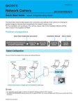
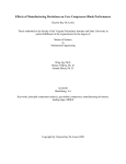
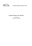
1
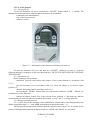
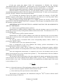
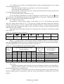
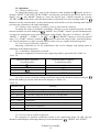
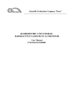
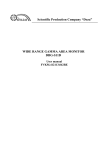
Scientific Production Company “Doza” DOSE-RATE METER/RADIOMETER MKS-15D “Snegir” User manual FVKM.412152.005RE Cont ent 1 Description and operation of the product ..……………………….…..……… 1.1 Product functionality ……………………………………….………….… 1.2 Technical characteristics .………………………………….…….….……. 1.3 Design and operation ………………….…………………………………. 1.4 Marking and sealing ……………………………………………….….…. 1.5 Packing .……………………………………………………………….…. 2 Intended use ……………………………………………………………..…… 2.1 Operational limitations .………………………………………………….. 2.2 Preparation of the product for use ..………………………….……..….… 2.3 Use of a product .....…………………………………………………….… 2.4 Adjustment ……………………………………………..………………… 3 Maintenance ……………………………………………………….………… 3.1 General notes ……………………………………………………….……. 3.2 Safety precautions ……………………………………...…………….…... 3.3 Maintenance routine ..……………………………..…………………...… 4 Calibration routine …………………………………………………………… 4.1 General requirements …………………………………...………….…..… 4.2 Preliminary arrangements ……………………………………………...… 4.3 Safety precautions ……………………………………………………..…. 4.4 Conditions ……………………………………………………………..…. 4.5 Procedure …………………………………….………………………..…. 5 Routine repairs ……………………………………….………………….…… 6 Storage ……………………………………………….…………………….… 7 Transportation ………………………………………..……………………… 8 Disposal ……………………………………...………….…………………… FVKM.412152.005RE 2 3 3 3 5 7 7 7 7 7 8 12 13 13 13 13 14 14 14 15 15 15 17 17 17 17 This User Manual contains information on design, principle of operation, characteristics of the product and instructions essential for correct and safe use of this product (intended use, maintenance, servicing, storage and transportation), as well as information regarding the utilization of the product. 1 DESCRIPTION AND OPERATION OF THE PRODUCT 1.1 Product functionality Dose-rate meter/radiometer MKS-15D “Snegir” (hereinafter - dosimeter) is intended for measurement of ambient equivalent dose * 10 (hereinafter - AED) and ambient equivalent dose rate * 10 (hereinafter - AEDR) of photon radiation and beta particle flux density. as well as for estimation of count rate at the combined measurement of gamma- and beta-radiation (hereinafter γ + β). The dosimeter is used for radiation survey at industrial enterprises; in ecological studies; checking of radioactive contamination of bank notes in banks; radiation measurements in housing premises, buildings and structures, and adjacent territories, household appliances, clothes, garments, soil surface of the homestead lands, vehicles. The dosimeter provides threshold excess alarm signals. 1.2 Technical characteristics 1.2.1 Energy range of measured gamma radiation …………………………… 0.05 to 3.0 MeV. 1.2.2 Measurement range: - AEDR of gamma radiation …………………………………………... 1·10-7 to 2·10-3 Sv·h-1 ; - AED of gamma radiation ……………………….………….……………….. 1·10-6 to 10 Sv. Note - At AED level less than 1·10-6 Sv the dosimeter serves as indicator and its measurement error is not normalized. 1.2.3 Limits of the permissible basic relative measurement error: - AEDR of gamma radiation ..………..………….…..…..….………………… (15+2/ Н ) %, where Н is a dimensionless unit, numerically equal to measured values of measured AEDR in μSv·h-1. - AED of gamma radiation ..………..……………..….…….………………….……… ±15 %. 1.2.4 Energy dependence relative to 0.662 MeV ……………..….……………………… 25 %. 1.2.5 Anisotropy of dosimeter for incident radiation in the solid angle ±60° relative to principal measurement direction (perpendicular to the upper rear part of the dosimeter): - for radionuclides 137Cs and 60Co ..…………………………………………………… 25 %; - for radionuclide 241Am …..…………………………….…..………………………… 60 %. 1.2.6 Energy range of measured beta radiation ………………………………… 0.1 to 3.0 MeV. 1.2.7 Measurement range of beta radiation flux density …..……………… 10 to 105 cm-2·min-1. 1.2.8 Limits of the permissible basic relative measurement error of beta radiation flux density …………………………………………………………………………………… ±(20 +200/P), where P is a dimensionless unit, numerically equal to measured values of measured beta radiation flux density in cm-2·min-1. 1.2.9 Warm-up time of the dosimeter …………………………………………….……… 1 min. 1.2.10 Continuous operation of the dosimeter when powered by two AA size alkaline batteries provided the illumination of the display is switched off and the level of background radiation is normal (at 20°C) .…………………….............................……………….…………………………… 400 hours. 1.2.11 Instability of readings within 6 hours of continuous operation ………….…….… ±10 %. 1.2.12 Dosimeter is powered by two AA size alkaline batteries. 1.2.13 Dosimeter is resistant to change in power supply voltage …..……...… from 1.8 to 4.0 V. FVKM.412152.005RE 3 1.2.14 Measured values of AEDR and AED of gamma radiation, beta radiation flux densities and count rate at the combined measurement (γ + β) are by turn displayed on the digital LCD display (hereinafter – display) with indication of signs of information compliance. Measurement units, in which the values are displayed: - AEDR of photon radiation ………………………………………………….….….… Sv×h-1 ; - AED of photon radiation ………………………………………………………………… Sv; - beta radiation flux density ………………………………………………..…….. cm-2×min-1 ; - count rate in the joint measurements (γ + β) radiation……..…………………….………. s-1. 1.2.15 Dosimeter beeps when gamma ray or beta particle hits the detector and when the given control threshold is reached. 1.2.16 Dosimeter is resistant to short-term, with duration 5 minutes, overloads of measured radiation with AEDR of gamma radiation up to 0.02 Sv·h-1. After exposure to overload the dosimeter maintains operability and basic relative measurement error within the limits stated in 1.2.3, 1.2.8. 1.2.17 Operating conditions: - operating temperature range …………….…….……………………… minus 20 to + 50 C; - maximum value of relative humidity ………….……….…….….…………. 90 % at +35 C; - atmospheric pressure ……………………………….………………….… 84.0 to 106.7 kPa; - content of the corrosive agents in the ambient air corresponds to the values in the Table 1.1. Table 1.1 Type of atmosphere Designation Designation I Relatively clean II Industrial Content of the corrosive agents Sulfur dioxide gas not more than 20 mg/(m2·day) (not more than 0.025 mg/m3); chlorides not more than 0.3 mg/(m2·day) Sulfur dioxide gas not more than 20 to 250 mg/(m2 ·day) (not more than 0.025 to 0.31 mg/m3); chlorides not more than 0.3 mg/(m2·day) 1.2.18 Limits of complementary measurement error for all the physical quantities to be measured due to deviation of temperature from normal value, per each 10 % .....…….…..……... ±5 %. 1.2.19 Limits of additional measurement error for all measured physical quantities at humidity of ambient air of 95% and at temperature of 35 С ……….….….……………………………… ±10 %. 1.2.20 Dosimeter is resistant to shocks after a free fall from a height of less than 750 mm. 1.2.21 Degree of protection provided by dosimeter’s casings against ingress of solid items and water ……………………..…………..……………………..………....……..………………... IP52. 1.2.22 Dosimeter is stable against electromagnetic interference of 2 grade according to IEC 61000-4-2-95, IEC 61000-4-3:2006, IEC 1000-4-8-93, IEC 1000-4-9-93. 1.2.23 Dosimeter is a fire-safe product with fire probability of fire not more than 10-6 year-1. 1.2.24 Dosimeter withstands the exposure of decontamination solutions: 1) trisodium phosphate or sodium hexametaphosphate (any synthetic detergent) – 10 - 20 g/l water solution; 2) 5 % citric acid solution in rectified alcohol. 1.2.25 Weight of the dosimeter, including batteries ……………………..….…………. 0.35 kg. 1.2.26 Overall dimensions of the dosimeter ……………………..….………… 1247235 mm. 1.2.27 Mean time to failure …………….……….………….…..….…. not less than 6000 hours. 1.2.28 Mean life time …………………..….….…………..…….….…..…. not less than 6 years. FVKM.412152.005RE 4 1.3 Design and operation 1.3.1 All the units of the dosimeter are installed in a compact plastic house. The at the top of the upper lid there is the display, to the left and to the right of the display the following control buttons are located, the shutter control lever and the battery compartment are situated lower. At the bottom of the cover there is a detector window which is closed by a shutter for beta radiation shielding during the photon and background AEDR radiation (hereinafter – background); the shutter is driven by a lever. The power switch is located in the upper part of the dosimeter’s side surface. 1.3.1.1 Control buttons of the dosimeter are as follows: (illumination) – press the button to turn on the illumination for 15 seconds, press the button at the illumination on to turn it off; - “MODE” – allows selecting windows of the display and switches the dosimeter from mode when automatic restart is enabled (symbol “->!->” on the display) into a mode when automatic restart is disabled (symbol “∞” on the display) and backwards when the button is pressed within more than 5 seconds; - “START” – resets the current value of the measured value and starts the new measurement cycle; (audible signal) – turns on or turns off beep accompanying the detected radiation. 1.3.1.2 The following modes of operation are available: with restart enabled (symbol “->!->” on the display or with restart disabled – infinite acquisition (symbol “∞” on the display). 1.3.1.3 The measurement results of different operation modes are shown on the display in the form of display windows for presentation of information: - current AEDR value in Sv/h-1, estimated error, in per cent (thereinafter – AEDR window); - current AED value accumulated since turn-on of the dosimeter or since the last restart of the current mode (thereinafter – DOSE window); - the value of beta radiation flux density in сm-2×min-1 at a continuous background account (thereinafter - β [сm-2×min-1] window); - the average count rate for gamma- and beta-radiation, in s-1 (thereafter - γ + β) window). The display windows have the following structure: - upper part: current operation mode - with autorestart (“->!->”symbol) or infinite acquisition (“∞” symbol); measured radiation: gamma (γ) or beta (β); confidence probability ( ), ( ) or ( ); presence or absence of sound, residual capacity of batteries; - middle part: the measured value with indication of dimension and the estimated error of the value (if provided); - bottom part: information about the current process of the background value measurement (the outside left symbol): 1) countdown timer (8 - 6 - 4 - 2) – period of dosimeter testing and background estimation; 2) hourglass symbol – background measurement; 3) “F” character – the background is measured and the dosimeter is ready for beta radiation flux density measurement; 4) if the control threshold is not set or not provided for the current mode, the set value of control threshold is indicated as «-------» symbol. 1.3.1.4 To choose the corresponding display window, press briefly the “MODE” button. Depending on the shutter position the display windows indicated in Table 1.1 are available. FVKM.412152.005RE 5 Table 1.1 - Display windows Button Shutter position Shutter is closed – measurement of Shutter is opened – measurement of beta background/AEDR/AED radiation flux density “AEDR” window “MODE” “START” “DOSE” window “β [сm-2×min-1]” window Turns the illumination on for 15 seconds. Pressing the button at the illumination on turns it off Switches between “AEDR” and “AED” Short pressing means nothing. display windows. When the button is When the button is press and held for more pressed for more than 5 seconds, the than 5 seconds, the dosimeter switches from dosimeter switches from autorestart mode autorestart mode “ -›!-› ” to infinite “ -›!-› ” to infinite acquisition mode “ ∞ ” acquisition mode “ ∞ ” and backwards and backwards Resets AEDR Resets accumulated Resets current value of the beta particles current value and AED, starts a new flux density and starts a new measurement starts a new measurement cycle cycle measurement cycle Turns on/off the beeps accompanying pulses detecting and buttons pressing Note - If the shutter is opened before the background measurement is terminated, the measurement of average count rate for beta and gamma radiation (γ + β) is started. 1.3.2 The detector converts gamma and beta radiation into a sequence of voltage pulses, the quantity of which is proportional to the intensity of radiation detected. Detector of ionizing gamma and beta radiation is the GM counter of Beta 2 type. Circuit of anode voltage generation, digital processing, control and indication performs the following functions: - scaling and linearization of detector counting response; - measurement of AEDR of gamma radiation and surface flux density of beta radiation by means of measurement of the average rate of pulses coming from the detector output; - measurement AED of gamma radiation by means of measurement of total amount of pulses at the detector output; - measurement AED accumulation time and real-time; - generation and stabilization of the detector anode voltage; - control of operation modes of the dosimeter; - display of measurement results at the indicator. Data processing and control circuit is made on the basis of the microprocessor and used for control of operation modes of the dosimeter, mathematical processing of pulse sequences from the detector, for control of indicator and audible signals. Anode voltage generator is used for generation of the anode voltage of + 400 V, required for the detector operation. For power supply of the processing and control circuit two AA-size batteries with total nominal voltage of 3.0 V are used. 1.3.3 To reduce the dosimeter response time to the AEDR changes, autorestart mode is used. When an arithmetic mean value of samples from last measurements deviates from the general arithmetic mean by an amount that exceeds the error of the general arithmetic mean by predetermined value, the start of new measurement is initiated. FVKM.412152.005RE 6 Thus, when the symbol “->!->” is indicated on the display, the automatic restart of AEDR measurement and beta radiation flux is enabled. It is performed both when the acquired count rate measurement value exceeds the predetermined limits and when the “START” button is pressed. Restart is accompanied by an audible signal. In case of automatic restart the signal is generated regardless of the audible signal blocked/permitted. In the infinite acquisition mode (“∞” symbol on the display) restart can be performed only by pressing the “START” button. In this case audible signal is not generated. 1.3.4 Statistical uncertainty of the indicated results is calculated on the basis of the established confidence probability. Conventional symbols of the confidence probability (reliability) displayed at the indicator are as follows: - completely shaded diamond ( ) corresponds 95 %; - unpainted diamond ( )corresponds 80 %; - dotted diamond ( ) corresponds 60 %. 1.4 Marking and sealing 1.4.1 The following information is presented at the dosimeter’s case: - trademark and/or name of the manufacturer; - reference designation of the dosimeter; - works number of a dosimeter according to the manufacturer's system of numeration; - degree of ingress protection provided by casings. 1.4.2 The dosimeter is sealed in accordance with the design documentation. 1.5 Packing 1.5.1 The dosimeter is packed into a carton which ensures protection against ingress of atmospheric precipitations and aerosols, splashes of water, dust, sand, solar ultra-violet radiation and also limits the ingress of water vapour and gases. 2 INTENDED USE 2.1 Operational limitations 2.1 Dosimeter retains operability under conditions stated in section 1.2. ATTENTION! UNDER TEMPERATURES BELOW 0 ºC THE DISPLAY RESPONSE IS SLOW! THIS IS NOT AN EVIDENCE OF THE DOSIMETER’S MALFUNCTION! 2.2 It is forbidden to use of the dosimeter at electrical substations of medium (6 - 35 kV) and high (above 35 kV). 2.3 When working in a dust environment, or during precipitation place the dosimeter in a plastic bag. 2.2 Preparation of the product for use 2.2.1 Unpack the dosimeter, perform external examination to determine the absence of mechanical damages. 2.2.2 Open the lid of the battery compartment and make sure that two batteries are in place, contacts are reliable and no salt is present on the elements as a result of a long-term storage of the dosimeter. If salt is present extract batteries out of the battery compartment and replace them. Install batteries in place according to polarity and close the lid of the battery compartment. FVKM.412152.005RE 7 2.3 Use of the product 2.3.1 Turning on/off To turn the dosimeter on, press and hold the “ON/OFF” button within 2 - 3 seconds. The information mentioned below indicates that the dosimeter is switched on: - trademark of the manufacturer; - type of the batteries used; - software version. Figure 2.1 – Information on the dosimeter indicator at its turn-on To turn the dosimeter off, press and hold the “ON/OFF” switch for at least 6 s until the following message is displayed on the recording indicator: “DEVICE IS SWITCHED OFF. RELEASE THE BUTTON”. 2.3.2 Operability test Before starting to use dosimeter: - familiarize yourself with location and purpose of the control buttons in accordance with 1.3.1.1; - turn the dosimeter on in accordance with 2.3.1 when the shutter is in extreme upper position “β”; - measure the background in accordance with 2.3.3; - by pressing the “MODE” button make sure that display windows “AEDR”, “DOSE” are switched over on the indicator; - transfer the shutter control lever to the extreme lower position “γ” and make sure that the measurement has started and the beta radiation flux density “β [сm-2×min-1]” is being indicated. 2.3.3 Background measurement 2.3.3.1 After turn-on the dosimeter starts simultaneous measurement of the background in the infinite acquisition mode “ ∞ ” and AEDR measurement in autorestart mode “ -›!-› ”. The background measurement continues until the statistical uncertainty 10 % is reached. In the process of background measurement display windows “AEDR” and “DOSE” are accessible. FVKM.412152.005RE 8 If the user opens the shutter before the measurement is finished, the messages “BACKGROUND IS NOT DEFINED”, “measurement of β will be possible not earlier than in (time before the measurement is finished) seconds” and the count rate measurement (γ + β) will start. When the background measurement is finished, ass the display windows are available. When the shutter is opened by means of a lever the display window “β [cm2×min]” is activated automatically and measurement of the beta radiation flux density starts. To start a new measurement, press the “START” button or close and open the shutter. 2.3.3.2 If during the dosimeter turn-on the shutter is opened, the message “CLOSE THE SHIELD” appears on the display. After that the dosimeter will switch over to the sleep mode. When the shutter is closed, the dosimeter starts background measurement. When the shutter is being closed and it is in a middle position, the message “MOVE THE SHUTTER TO THE EXTREME POSITION” is displayed. This message is warning and doesn’t affect the dosimeter operation modes. ATTENTION! WITH THE SHUTTER IN A MIDDLE POSITION THE MEASUREMENTS ARE NOT PERFORMED. 2.3.4 Measurement of AEDR of photon radiation Measurement of AEDR of photon radiation starts when the dosimeter turns on at the shutter closed and is carried out only in the gamma radiation measurement mode. The dimension is Sv×h-1 or its submultiple units. 2.3.5 Measurement of AED of photon radiation Measurement of AED of photon radiation starts when the dosimeter turns on at the shutter closed and is carried out only in the gamma radiation measurement mode. The dimension is Sv or its submultiple units. To view the values of measured AED, select corresponding display window “DOSE” by pressing the “MODE” button. 2.3.6 Measurement of the beta radiation flux density Prior to measurement of the beta radiation flux density perform measurement of the background gamma radiation according to 2.3.4. The most accurate results will be obtained if during the background gamma radiation measurement the dosimeter is located parallel to the surface to be measured and at a minimum distance from it. After the background measurement is completed, don’t move the dosimeter and open the shutter by moving the lever to the extreme lower position “γ”. The measurement of the beta radiation flux density will start automatically. The measured value on the display of the beta radiation flux density and statistical uncertainty of the measured value will be indicated in the display window “[cm-2×min-1 ]”. The dimension of the measured value is cm-2×min-1. Each detected particle is accompanied by an audible signal, if the sound is on according to 2.3.6. F n n 0 , (2.1) where n is the total count rate of beta and gamma radiation at the shutter opened; n 0 is the count rate of gamma radiation with the shutter closed; is the sensitivity of the open detector to beta radiation. The dosimeter was calibrated by the manufacturer using the beta spectrum energy of 2284 keV). FVKM.412152.005RE 9 90 Sr(90Y) source with the cutoff When beta radiation flux density from other nuclides is measured, the correction factor for dependence of the detector sensitivity on the beta radiation energy is required. Correction factors for dependence of the detector sensitivity on the beta radiation energy for some beta radionuclides are presented in the Table 2.1. Table 2.1 Niclide Correction factor 90 Sr(90Y) 1,0 204 Tl 1,7 60 Co 2,8 14 C 11,0 2.3.7 Count rate alteration at the combined (γ + radiation measurement To measure the average beta and gamma radiation count rate, move the shutter control lever to the extreme lower position until the background measurement is finished, - that is, until “F” character appears in the outside left corner of the indicator. The message “BACKGROUND IS NOT DEFINED” appears on the indicator; the background measurement is not stopped. After that the average count rate value (exclusive of factors), in s-1, and the “MONITORING” message are displayed on the indicator. In the headline of the window the “γ+” symbol is indicated. The measurement is resumed when the shutter is closed. 2.3.8 Control threshold setting 2.3.8.1 Control threshold may be set only for AEDR photon radiation measurement and beta flux density measurement modes. The control threshold is controlled: 1) at the shutter closed (the extreme upper position of the lever – “”) – for the AEDR photon radiation measurement mode; 2) at the shutter opened (the extreme lower position of the lever – “γ”) – for the beta flux density measurement mode. 2.3.8.2 Values of the set control threshold during the measurement: - photon measurement AEDR: from 0,01 μSv·h-1 to 9,99 Sv·h-1 ; - beta radiation flux density: 1,0 to 9,99·106· cm-2·min-1 ; - the threshold values on default: switched off. 2.3.8.3 To set the control threshold values: 1) press the “START” button at the dosimeter switched off and hold it to turn on the dosimeter: on the upper part of the indicator the message “SELECT POSITION” appears; release the button; 2) use the and “MODE” buttons to set the required position: - AERD photon radiation threshold – Lγ, - beta flux density threshold - L; 3) press the “START” button: on the upper part of the indicator the “EDITION” message appears; release the button; 4) set the required value using the and “MODE” buttons; 5) confirm the set value pressing the “START” button or cancel it pressing the button; at that the dosimeter switches over to the position selection mode; 6) to exit the mode, press the button and turn off the dosimeter pressing the on/off button. 2.3.9 Turning audible signal on/off 2.3.9.1 When the dosimeter is turned on, sound is turned on automatically; it is indicated as the symbol at the top of the display window. To turn the sound off, press the button. The symbol of crossed speaker will show that the sound is turned off. To turn the sound on, press the button again. FVKM.412152.005RE 10 2.3.9.2 When the value of the set control threshold is reached, sound signal turns on. It is turned off in the following cases: - if the value measured within 8 seconds doesn’t exceed the set threshold; - at the shutter being opened/closed; - for 20 seconds - if any button is pressed; at that the button function is being operated; after 20 seconds the sound signal will resume. 2.3.10 Turning the display illumination on/off To turn the display illumination on without changing the operation mode, press the button for a short time. The illumination will turned off automatically in 15 seconds. If within this period the button is pressed again, the illumination will turn off. 2.3.11 Battery replacement The dosimeter’s power supply voltage is in the range 4 to 1.8 V. The dosimeter can operate when the voltage drops down to 0.9 V, but take into account that during startup the dosimeter consumes current of up to 50 mA, and thus fully discharged batteries can not provide the required starting voltage. The foregoing also applies to the case when one battery is deeply discharged and the other battery is fully operable. In the upper part of the display window the residual capacity of batteries is indicated according to the Table 2.2. Table 2.2 – Residual capacity of batteries Symbol Capacity of batteries (%) More than 90 % 90÷70 % 70÷50 % 50÷30 % 30÷10 % Less than 10 % When symbol appears on the display, batteries should be replaced. To replace batteries, open the battery compartment and insert two alkaline batteries of AA-size in accordance with polarity. The following batteries can be used in the dosimeter (see Table 2.3). Table 2.3 – Types of batteries be used for power supply Typical Typical residual capacity voltage capacity (Ah) Type of specific attribute (for two batteries) battery Rload=10 for GP batteries 90 % 70 % 50 % 30 % 10 % Ohm NiCd 2.68 2.60 2.54 2.48 2.30 1.3 ÷ 2.7 Marking NiMh 2.60 2.52 2.48 2.44 2.30 1.8 ÷ 2.4 Marking ZnCl 2.74 2.40 2.20 2.00 1.90 0.5 ÷ 0.8 Green case Alkaline 2.88 2.70 2.58 2.40 2.20 2.5 ÷ 3.0 Marking, golden case CZn 2.64 2.24 2.14 2.02 1.90 0.3 ÷ 0.6 Grey case Please note: - potential and residual capacity depend on the type of batteries and their correct installation; - indicated residual capacity is for reference only, the dosimeter does not take any action if the potential drops below acceptable limit; - residual capacity is calculated on the basis of measured potential of two tandem batteries, and thus readings may not correspond to reality due to the deep discharge or malfunction of one of the batteries. FVKM.412152.005RE 11 2.4 Adjustment 2.4.1 Change of battery type To change the battery type, turn on the dosimeter while holding the button pressed; a message “SELECT THE TYPE OF BATTERY” and currently used battery type will be shown on the display. Use and “MODE” buttons to select the desired type; confirm selection by pressing “START” button in this mode; after that the dosimeter will switch over to the working mode. Use button to exit the selection mode. At that, the dosimeter will switch over to the working mode and the previous type of batteries will remain unchanged. 2.4.2 Change of the confidence probability value (predetermined reliability) To change the value of confidence probability, switch over to the engineering mode. For that, turn the dosimeter on while holding the , “MODE” and “START” buttons pressed simultaneously. A request for entering the access code will appear on the display. The code is as follows: “START"-> “MODE”-> “MODE”-> “START”-> “START”. Use and “MODE” buttons to select the required value. Use “START” button to confirm or button for cancel the entered value, turn the dosimeter off. Turn the dosimeter on, make sure that required value is set (see symbol in the message line). 2.4.3 Correction of adjusting coefficients Adjusting coefficients are set by manufacturer and can be changed only during repair or calibration in the engineering mode. 2.4.3.1 Alternative assignment of controls Alternative assignment of controls in the engineering mode is presented in the Table 2.4. Table 2.4 Function (name) of buttons in working mode Function (name) of buttons in engineering mode “↑” “↓” “ESC” “ENTER” “MODE” “START” 2.4.3.2 For review of current working coefficients turn on the dosimeter while pressing the button and, holding it pressed, read data on the display (see Table 2.5). Table 2.5 Indicated data Meaning ALKALINE Kv 104 Battery type used for calculation of residual capacity ADC correction coefficient Kf Kx Km K1 К2 К3 Correction coefficient for the detector’s background Conversion coefficient “Dead time” Transition coefficient to beta radiation flux density Conversion coefficient 2 Conversion coefficient 3 0.00e+00 2.20e-07 2.20e-05 1.45e+01 0.00e+00 0.00e+00 2.4.3.3 Correction of workout coefficients For correction of workout coefficients switch to the engineering mode; for that, turn the dosimeter on holding the following buttons pressed simultaneously: , “MODE” and “START”. FVKM.412152.005RE 12 1) For correction of coefficients: - enter the access code – – – “MODE” – ; - “SELECT POSITION” – select required position using “↓” and “↑” buttons; - “EDITION” – switch over to the edit mode by pressing the “ENTER” button; - enter required coefficient value using “↓”, “↑” buttons; - confirm the newly set value by pressing “ENTER” button or cancel it by “ESC” button; turn the dosimeter off; - turn the dosimeter on by pressing button, make sure that all data are set correctly. 2) For correction of the ADC correction coefficient: - enter the access code – – “START” – “MODE” – “MODE”; - using “↓”, “↑” buttons enter the coefficient value for which the voltage indicated on the display corresponds to the voltage measured at the terminals of the power connector; - confirm the newly set value by pressing “ENTER” button or cancel it by “ESC” button; turn the dosimeter off; - turn the dosimeter on by pressing button, make sure that data are set correctly. 3) Setting of default coefficients: - enter the access code “MODE” – “MODE” – “START” – – ; - after entering the access code the dosimeter will write to the EEPROM universal default set of coefficients presented in Table 2.5. 3 MAINTENANCE 3.1 General notes Maintenance is performed with the purpose of ensuring reliable, long-term operation of dosimeters. No special qualification or workplace arrangement is required. 3.2 Safety precautions 3.2.1 Before beginning to work with dosimeter familiarize yourself with this User Manual. 3.2.2 During all operations with dosimeter follow occupational and radiation safety requirements of current safety instructions in the company (enterprise). 3.2.3 Intended use of the dosimeter does not present danger for the user and environment. 3.2.4 The dosimeter does not contain external parts, on which dangerous voltage could be present. To protect the user from accidental touching of the conductive parts the dosimeter is equipped with protective case. ATTENTION! DO NOT OPEN OR RECHARGE GALVANIC BATTERIES! 3.3 Maintenance routine 3.3.1 Maintenance is divided into routine and periodic. 3.3.2 Routine maintenance 3.3.2.1 Routine maintenance is carried out during regular operation; it includes inspections of a dosimeter for timely detection and elimination of factors which can compromise their operability and removing batteries before long-term storage. 3.3.2.2 The following main types and periodicity of routine maintenance are recommended: - visual inspection ………………………………………….………....…….. every month; - cleaning of external surfaces (decontamination) .……………….…..…..… every month. 3.3.2.3 Cleaning of external surfaces of a dosimeter is performed in accordance with work schedule at the company (facility) with solutions indicated in 1.2.25. After washing surfaces using clothes moisten with distilled water dry them with filter paper. FVKM.412152.005RE 13 Dry cleaning can be performed with any periodicity. 3.3.2.2 Remove the batteries each time before long-term storage of the dosimeter. To do this proceed as follows: - turn the dosimeter off; - remove the lid of the battery compartment; - take the batteries out of the battery compartment; - review the battery compartment, check condition of terminals, clean contamination in the battery compartment and remove oxide from terminals; - make sure there is no moist, no spots of salts on the surface of batteries and no damage of insulation either; - install the lid of the battery compartment. 3.3.3 Periodic maintenance Periodic maintenance consists of calibration of dosimeter. 4 CALIBRATION ROUTINE 4.1 General reguirements 4.1.1 Calibration of a dosimeter is performed in accordance with the IEC 61453:2007. 4.2 Preliminary arrangements 4.2.1 Operations performed during calibration are listed in Table 4.1. Table 4.1 – List of calibration operations Operation Section External examination Testing Determination of basic relative measurement error of AEDR of photon radiation Determination of basic relative measurement error of AED of photon radiation Determination of basic relative measurement error of beta radiation flux density 4.5.1 4.5.2 4.5.3 4.5.4 4.5.5 4.2.2 Primary and auxiliary tools and equipment necessary for calibration are presented in the Table 4.2. Table 4.2 – Primary and auxiliary tools and equipment for calibration Section 4.5.3, 4.5.4 4.5.5 4.5.4 4.5.3, 4.5.4, 4.5.5 4.5.3, 4.5.4, 4.5.5 4.5.3, 4.5.4, 4.5.5 Name and type (designation) of primary or auxiliary calibration tool, document that regulates technical requirements and/or metrological and main technical characteristics of the calibration tool Calibration installation UPGD-2M-D, UPGD or equivalent, range of reproduced AEDR – from 5·10-7 to 5·10-2 Sv·h-1. Set of sources 4SO, range of reproduced beta radiation flux density from 10 to 104 cm-2·min-1 Stopwatch with measurement range 1 to 3600 seconds Thermometer with measurement range 0 to 30 °C and scale interval 0.1 °C Psychrometer with measurement range 20 to 90 %, error ±6 % Barometer with measurement range 60 to 120 kPa and scale interval 1 kPa N o t e - It is allowed to use other tools and equipment with similar characteristics ensuring determination of metrological characteristics of dosimeters with required precision. FVKM.412152.005RE 14 4.3 Safety precautions It is necessary to follow safety requirements described in section 3.2 and in documentation accompanying calibration tools and equipment. 4.4 Conditions The following normal operating conditions shall be met during calibration: - air temperature ………………………………………..…….…………………. +(20 ±5) °C; - relative air humidity ……….………………………….......……..……...… from 30 to 80 %; - atmospheric pressure ………………………………….……………….… 86.0 to 106.7 kPa; - natural radiation background ………………..……….………… not more than 0.25 μSv·h-1. 4.5 Procedure 4.5.1 External examination Items to be checked during external examination: - proper completeness; - availability of operational documentation; - absence of defects which could affect the dosimeter’s operation. 4.5.2 Testing Testing of the dosimeter is carried out in accordance with 2.3.2. The dosimeter is operable, if the measured background value is indicated on the corresponding indicator windows. 4.5.3 Determination of basic relative measurement error of AEDR of photon radiation Determine the basic relative measurement error of AEDR of photon radiation at values of gamma radiation of 10 and 1500 μSv·h-1 in the autorestart mode (“->!->” symbol on the display). Perform the calibration as follows: 1) Place the dosimeter on calibration installation with rear panel towards the source; the center of dosimeter’s sensitive area (upper rear part of the dosimeter at depth 10 mm) shall be located at the central axis of the gamma radiation beam at a distance from the source corresponding to reference AEDR value; 2) turn the dosimeter on according to 2.3.1; 3) expose dosimeter to radiation and take readings in the display window “AEDR” when the statistical error of less than 5 %; 4) perform at least three measurements for each test point; * , μSv·h-1 by the 5) for each test point calculate the arithmetic mean of the measurements H срj following formula 3 Н * meanj Н i * i 1 3 (4.1) 6) for each test point calculate the basic relative error j in per cent by the following formula 2 *mean H *oi H j j 1,1 100 2CAL , * H oi (4.2) * is the value of AEDR, reproduced by the calibration installation, μSv·h-1 ; where H оi CAL is the uncertainty of the calibration installation (from the calibration certificate), in per cent. The results of calibration are considered satisfactory if the basic relative measurement error for all test points does not exceed the corresponding limits stated in the section 1.2.3. FVKM.412152.005RE 15 4.5.4 Determination of basic relative measurement error of AED of photon radiation Determination of the basic relative measurement error of AED shall be performed with one value of AED equal to 100 μSv. Perform calibration as follows: 1) Place the dosimeter on calibration installation with rear panel towards the source; the center of dosimeter’s sensitive area (upper rear part of the dosimeter at depth 10 mm) shall be located at the central axis of the gamma radiation beam at a distance from the source for which the AEDR value is within the measurement range stated in 1.2.2; 2) turn the dosimeter according to 2.3.1; 3) start exposing the dosimeter to radiation and turn on the stopwatch simultaneously; 4) stop exposure at the AED value of 100 μSv and take readings from the display window “AEDR” when the statistical uncertainty is less than 5 %. 5) perform no less than three measurements for this test point; calculate the arithmetic mean of the measured values; 6) calculate the basic relative error in per cent by the following formula 2 * t Н *mean H 2 o 1,1 100 CAL * t H o (4.3) where H*ср is the arithmetic mean of three AED measurements in the test point, μSv; * t is the reference value of AED, μSv; H o t is the duration of exposure, hours. The results of calibration are considered satisfactory if the relative measurement error of AED of photon radiation does not exceed the limits stated in the section 1.2.3. 4.5.5 Determination of basic relative measurement error of beta radiation flux density Determine the basic relative measurement error of beta radiation flux density at values of flux density 400 and 1000 cm-2 ·min-1 . Perform calibration as follows: 1) turn the dosimeter on according to 2.3.1; 2) perform the background measurement with the detector window closed by the shutter; 3) open the shutter pushing the control lever to the lower extreme position “γ”; 4) place the dosimeter with an open detector window above the surface of the source for 2 mm so that all the work surface of the detector is located over the active surface of the source; 5) take readings from the display window “β [cm-2 ×min-1]” on the indicator; 6) perform at least five measurements of beta radiation flux density for each test point, calculate the arithmetic mean value for each test point; 7) for each test point calculate the basic relative error of beta radiation flux density in per cent by the following formula i Pi Pref 100 , Pref (4.3) where Pi is the arithmetic mean value of beta radiation flux density,·cm-2·min-1 ; Pref is the value of beta radiation flux density reproduced by the reference source, cm-2·min-1. The result of calibration is considered satisfactory if none of the calculated relative measurement error of beta radiation flux density exceeds the limit stated in the section 1.2.8. FVKM.412152.005RE 16 5 ROUTINE REPAIRS 5.1 Possible problems and their solutions are shown in the Table 5.1. Table 5.1 - Possible problems and their solutions Problem Possible cause Dosimeter won’t turned on Batteries are discharged No contact between batteries and terminals of the battery compartment Failure of one of batteries Solution Replace batteries Restore contact between batteries and terminals Replace a faulty battery 5.2 In case you can not solve the problem listed in the Table 5.1 or when a more complex problem occur, send the dosimeter for repair to corresponding repair service or to the manufacturer. 6 STORAGE 6.1 Prior to putting into operation dosimeter shall be stored in a heated warehouse with natural ventilation: - in manufacturer’s package – at ambient temperatures from +5 to +40 C and relative humidity up to 80 % at +25C; - unpacked – at ambient temperatures from +10 to +35 C and relative humidity up to 80 % at +25 C. 6.2 The storage location should be free of dust, chemical vapours, aggressive gases and other substances that may cause corrosion. The storage location shall exclude exposure of dosimeters to the direct rays of sunlight. 7 TRANSPORTATION 7.1 Dosimeters in the original manufacturer’s package can be transported by all means of transport at any distance: - transportation by railway shall be carried out in clean boxcars; - when transported by air the boxes with dosimeters shall be placed in air-tight heated compartment; - when transported by water and sea transport the boxes with dosimeters shall be placed in the hold. 7.2 Arrangement and fastening of the boxes on transport means shall provide their steady position en route, absence of displacement and striking each other. 7.3 The requirements of the inscriptions on the transport packing shall be observed during loading and unloading. 7.4 Transportation conditions are as follows: - temperature …………………………………………………..….. from minus 25 to +50 °C; - humidity …………………………………….………………....…..… up to 95 % at +35 °C; - impacts with peak shock acceleration 98 m·s-2, duration of impact 16 ms, number of shocks from each direction not less than 1000. 8 DISPOSAL 8.1 No special requirements for disposal of the dosimeter are made. FVKM.412152.005RE 17