1
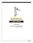
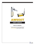
AW900i
User’s Manual
Point-to-point
Industrial-grade, ultra-long-range 900 MHz
non-line-of-sight wireless Ethernet systems
AW900i
User’s Manual
Non-line-of-sight :: 900 MHz
AW900i Kit
Thank you for your purchase of the AW900i
point-to-point wireless Ethernet bridge.
Long-range 900 MHz wireless indoor Ethernet
bridge. Kit includes:
n
— (2) AW900i indoor radios
n
— (2) 110 VAC to 6 VDC power adapters
n
— (2) AW2 2.5 dBi omni-directional antennae
If you have any questions when configuring
your AvaLAN system, please send an e-mail
to [email protected].
For a live technician, please call technical
support at (650) 384-0000.
Or upgrade to AW5H-900, AW5P-900, AW6, AW10, AW11, or AW15
— all FCC approved
For advanced installation information,
please visit www.avalanwireless.com.
Operational summary
The AW900i replaces costly wiring with a wireless Ethernet bridge that can enable remote Wi-Fi access points, Ethernet pan/tilt/zoom
security cameras, VoIP phones, or Internet kiosks. AvaLAN’s product offers the ideal combination of price, range, data rate, security,
interference avoidance, quality-of-service, and ease-of-use.
The AW900i is the best solution when:
— a Broadband Ethernet drop will cost too much or is impractical to install
— guaranteed DSL-rate throughput is required (kiosks/Wi-Fi access points/PTZ cameras)
n
— guaranteed latency for voice or video is required (PTZ cameras/VoIP)
n
— Wi-Fi is too slow due to saturation or 2.4 GHz interference (airport/mall/PTZ cameras)
n
— an indoor long-range broadband backhaul is required
n
n
Features include:
— does not interfere with Wi-Fi networks
— Highest Quality of Service (QoS) available — synchronous point-to-point protocol enables extremely low data latency and
— jitter (surveillance video and VoIP)
n
— 128 bit encrypted payload protection provides secure data delivery
n
— simple plug and play — pre-configured as matched pairs with no user programming required
n
— operates in the 902-928 MHz band and does not require an FCC license to operate or install
n
— VLAN extensions supported
n
n
Technical support :: (650) 384.0000
PAGE 2
www.avalanwireless.com
User’s Manual
AW900i
Quick setup
1)
2)
3)
4)
Attach an AW2 antenna to each radio.
Plug in the AW900i using the power adapter.
Connect an Ethernet cable from each AW900i to a network device.
Send Ethernet traffic. For troubleshooting, see Page 4.
System diagram
Each AW900i radio automatically selects the best radio channel, encrypts the Ethernet traffic, and transports the data wirelessly to its
mate. Any Ethernet device can be connected to the AW900i. The AW900i functions in place of an Ethernet cable and provides a transparent wireless point-to-point Ethernet cable replacement. Crossover cables are not necessary as the AW900i automatically senses the
device (client or switch).
Power adapter
110 VAC
AW900i
Ethernet
RJ45/10BaseT
900 MHz
digital
Ethernet
bridge
Power adapter
110 VAC
Ethernet
RJ45/10BaseT
AW900i
www.avalanwireless.com
PAGE 3
Technical support :: (650) 384.0000
AW900i
User’s Manual
LED display
Troubleshooting
See the online installation tutorial and FAQ at www.avalanwireless.com.
No Power LED
Check the power connections.
No Radio Link LED
The radio is looking for its matched partner. If both units are powered up and the Power LEDs are active, they may be too far away
to create the radio connection. Try other locations that may have a less obstructed path or try to reorient the antennae. Yagi type
antennae get their best range when they are oriented to point directly at each other with the antenna elements oriented in the
same place (eg. vertically or horizontally).
Radio LINK LED is on but Link Quality Indicator is low
The units may be too far away to create a good radio connection. Try other locations that may have a less obstructed path, or try to
reorient the antennae.
No Ethernet LINK LED
Check your network connections.
Installing multiple systems in close proximity
See the online installation tutorial and FAQ at www.avalanwireless.com
Still not working?
Temporarily use an Ethernet cable to see if the network is working over a wired connection. If an Ethernet cable does not work
then the problem is with the network.
Technical support :: (650) 384.0000
PAGE 4
www.avalanwireless.com
User’s Manual
AW900i
Advanced settings
Automatic frequency selection mode (DIP switches — all OFF for automatic mode)
The AW900i is designed to automatically select and continuously optimize the performance of its radio channel. The radio channel
is monitored to ensure it is providing low error rates necessary for successful radio transmission. In the event that the error rate
rises, the AW900i will autonomously change to a new channel. There are 12 non-overlapping channels.
Manual frequency selection mode
To restrict the operation of the AW900i to a subset of the 902-928 band, the user may activate a manual selection mode that allows
the radio to automatically choose the best channel within a grouped subset of the 12 available channels. This is enabled by the 8
position DIP switch on the master unit. These settings allow the AW900i to operate on the optimal channel in one of three subsets,
LOW 4, MID 4, or HIGH 4. The DIP switch settings are:
Or, the user may wish to select a specific channel. This can be done by setting DIP switches 5-8 as shown in the table below (turn
DIP 2 Off / 3 Off).
Site survey mode (DIP switch 4 — default is OFF for normal operation)
In this mode, the AW900i can perform a site survey. With this mode activated, the radios send and receive at 100 percent capacity
by transceiving self-generated simulated data. The installer can monitor the Link Quality display to assess channel quality while
optimizing antennae orientation. The installer can manually select each channel to evaluate performance and identify the best
channels for operation. By identifying channels with poor performance it is possible to identify possible interferers and use “manual
frequency selection mode” to avoid portions of the band or select a fixed operating frequency.
Note: Ethernet traffic does not get transported while the radios are in this mode.
www.avalanwireless.com
PAGE 5
Technical support :: (650) 384.0000
AW900i
User’s Manual
Technical specifications
CHARACTERISTIC
SPECIFICATION / DESCRIPTION
RF transmission rate
Ethernet throughput
Output power
Receive sensitivity
Latency
Voltage
Current consumption
Radio channels
Automatic frequency select
Manual frequency mode
Status LEDs
Error correction technique
Adjacent-band rejection
Temperature range
Power over Ethernet
Size
1.536 Mb/s
935 Kb/s
+21 dBm (4 Watts EIRP used with 15 dBi antenna)
-100 dBm at 10e-4 BER (-112 dBm with 15 dBi antennae)
< 1 ms — assuming a dedicated wireless link to client device
5-9 VDC
RX 260 mA TX 350 mA
12 non-overlapping
Yes — radio channel automatically selected and adaptively optimized
Yes
Power, RF Link, Ethernet Link, Traffic, RF RX, RF TX, 4/Channel, and 6/Link Quality
Sub-block error detection and retransmission
> 60 dB — SAW receiver filter attenuates cellular and pager interference
-40o C to 70o C
Compatible with common 5V splitters (Linksys WAPPOE)
150 x 85 x 35 mm
Sample application
HOTEL LAYOUT USING THE AVALAN WIRELESS BRIDGE
CAT5 Ethernet cable
Wi-Fi Channel 1
Wi-Fi Channel 6
Wi-Fi Channel 11
AP
[
AW
AP
Wi-Fi Access Point
AW
AvaLAN Wireless Ethernet Bridge
Front office
with 768 Kb/s
T1 service
AW
AP
[
AW
AP
Hotel rooms
AW
Technical support :: (650) 384.0000
AW
AP AW
[
[
T1
PAGE 6
www.avalanwireless.com
User’s Manual
AW900i
Warranty
This product is warranted to the original purchaser for normal use for a period of 180 days from the date of purchase. If a defect
covered under this warranty occurs, AvaLAN will repair or replace the defective part, at its option, at no cost. This warranty does not
cover defects resulting from misuse or modification of the product.
Range
www.avalanwireless.com
PAGE 7
Technical support :: (650) 384.0000
[email protected]
Technical support :: (650) 384.0000
For advanced installation information visit
www.avalanwireless.com
©2004 — 2007 AvaLAN Wireless Systems Incorporated. All rights reserved. AvaLAN Wireless and the AvaLAN Wireless logo are registered trademarks of AvaLAN Wireless Systems
Incorporated. All other trademarks are property of their respective owners. AvaLAN Wireless makes no representations or warranties with respect to the accuracy, utility, or
completeness of the contents of this publication and reserves the right to make changes to specifications and product descriptions at any time without notice. No license, express
or implied, by estoppel or otherwise, to any patents or other intellectual property rights is granted by this document. Particular uses or applications may invalidate some of the
specifications and/or product descriptions contained herein. The customer is urged to perform its own engineering review before deciding on a particular application. AvaLAN
Wireless products are not designed for use in medical, life saving, or life sustaining applications. 07.07.2007