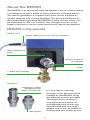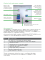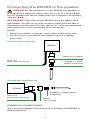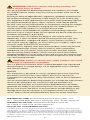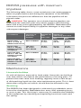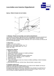
1
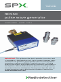
Q ui c k S ta r t U se r G ui d e RD550 pulse wave generator 90/ UG101I NT/01 I SSU E 1 12/2014 Important: This guide provides basic operation instructions and is intended as a field reference only. It also contains important safety information and guidelines and should be read in its entirety before attempting to operate the RD550. Detailed instructions, including product specification and troubleshooting information are available in the Operators’ Manual. Radiodetection products, including manuals, are under continuous development. To ensure you have the most up to date information, please download the Operators’ Manual from www.radiodetection.com. About the RD550 The RD550 is an electronic valve designed to assist in the locating of underground pipes made of many materials including plastic. The device generates a compression wave inside the pipe by quickly opening and closing the pipe. The pressure differences that result when operating the RD550 create sounds which can be measured on the soil surface. The strongest noises at the highest frequency can be measured directly above the pipeline. RD550 components Valve unit Power cable (connects to control unit battery) Valve maintenance point Piston connection (2 supplied) Outlet 1" Geka claw coupling Pistons Long piston, creates stronger pressure waves, use with care It is possible to vary the strength of the pressure wave created by the RD550 using the different pistons provided. The larger piston creates a stronger pressure wave. As stronger pressure waves put the pipe infrastructure under greater stress we recommend starting with the shorter piston. Short piston 2 Control unit and power supply 12V LED lights when automotive power source is in use Battery LED flashes when charging, remains lit when charged Mode switch toggles between quick and slow settings for pulse waves ON / OFF switch Valve unit power connection point Battery charger socket Mode LED flashes fast or slow to indicate setting Accessory kit The RD550 is supplied with a 1" Geka claw coupling which has a 1" BSP (British Standard Pipe) female thread. For regions where NPT (National Pipe Thread) is common, a 1" BSPP to 1" FNPT adaptor is supplied in the box. An accessory kit (part number 10/RD550NPTFITTINGS) is also supplied in some geographical regions. It contains: Qt y Des cr i pti o n 12½" FNST to 1" male NPT, fire hydrant adapter 1¾" Garden Hose Thread (GHT) to 1" NPT swivel adapter 11" female 45° elbow 11" female NPT to 1¼" male NPT adapter 11" male NPT to ¾" female NPT adapter 11" NPT lever ball valve 24" long nipple, fitting 1" male NPT 1 Roll of ½" thread seal tape 1 4 foot length of ½" ID hose These components allow the user to configure the pipe connections illustrated in the diagrams on page 5 of this user guide. 3 Connecting the RD550 to the pipeline WARNING: The mechanics of the RD550 are capable of withstanding a maximum water pressure of up to 116 psi/8 bar. Do not operate the device under pressure conditions exceeding 116 psi/ 8 bar. Important: The outlet on the RD550 unit must always face downwards. For the unit to work correctly water must be able to flow freely from the outlet. For this reason, it is also recommended that a drain line is only connected when necessary. Note: • Do not use elbows or bends, unless absolutely necessary. • Do not use hose or flexible line (apart from the supplied drain line). Preferred positioning RD550 GEKA claw coupling Drain Line (Only when necessary) 1" BSPP x 1" FNPT adaptor (if required) Acceptable positioning RD550 Drain Line (Only when necessary) 1" BSPP x 1" FNPT adaptor (if required) GEKA claw coupling Example connections The following examples illustrate how to connect the RD550 to different devices: 4 Water meter connection Existing water meter GEKA claw coupling RD550 1 2 3 2 4 6 5 Fire hydrant connection GEKA Fitting RD550 1 2 3 7 6 Fire Hydrant Hose bib Sprinkler/hose bib connection GEKA coupling 10 RD550 9 1 2 8 5 6 Note: This positioning may result in reduced performance as it uses a 45° elbow (item 8). Although, not recommended, it is necessary to keep the RD550 in one of the acceptable positions. 1 1" BSP x 1" NPT adapter (use only if required) 2 4" long nipple, fitting 1" male 3 1" lever ball valve, fitting female 4 1" female to 1¼" male adapter 5 ½" ID hose, 4' Long fit (drain line, use only if required) 6 ½" thread seal tape 7 2½" fire hydrant to 1" male adapter 8 1" female 45° Elbow 9 ¾" to 1" adapter 10 ¾" swivel adapter (May require Garden Hose Thread in some regions) 5 WARNING: Failure to comply with safety warnings can cause serious injury or death You are responsible for determining whether the conditions are suitable for using this device. Always carry out a risk assessment of the site to be inspected. Ensure you follow all applicable laws, regulations, guidelines and policies for the location, excavation, inspection or fault analysis of a sub-surface utility. This equipment is NOT approved for use in areas where potentially explosive (or otherwise hazardous) gases, vapors, liquids or solids may be present. Do NOT carry out any measurements on components carrying live voltages. The power supply is intended for charging the unit’s battery indoors. It should not be used outdoors or in the presence of water. The mechanics of the RD550 are capable of withstanding a maximum pressure of up to 116 psi/ 8 bar. Do not operate the device under pressure conditions exceeding 116 psi/ 8 bar. This product does not indicate the depth of sub-surface utilities. Additionally, it does not detect buried electrical power lines, gas lines or other hazardous underground objects. If you intend to uncover a sub-surface utility by digging, you must follow your company, region and country’s codes of practice for excavation. It is important to regularly clean and sanitise products which may become contaminated through contact with foul water or other contaminants Headphone use: you need to remain alert to traffic and other hazards that are normally heard outdoors. Always turn the volume down before plugging headphones into an audio source and use only the minimum level necessary to take your measurements. Excessive exposure to loud sounds can cause hearing damage. CAUTION: Failure to comply with safety cautions can result in damage to equipment or property This is a precision instrument which could be damaged if left unprotected during transport or storage. Always use an appropriate case to transport and store this device. NOTES This equipment is designed for use by competent personnel, following procedures and instructions described in the full user manual. For comprehensive warning and safety information, refer to the full operators’ manual. You are responsible for determining whether you consider the measurement results to be valid and for any conclusions that are reached or any measures that are taken as a result thereof. Radiodetection can neither guarantee the validity of any measuring results nor can we accept liability for any such results. We are on no account able to accept liability for any damage which may be caused as a consequence of the use of these results. Please see the Standard Warranty Terms for further information. Radiodetection (USA) 28 Tower Road, Raymond, Maine 04071, USA Tel: +1 (207) 655 8525 Toll Free: +1 (877) 247 3797 [email protected] Radiodetection Ltd. (UK) Western Drive, Bristol BS14 0AF, UK Tel: +44 (0) 117 976 7776 [email protected] www.spx.com www.radiodetection.com © 2014 Radiodetection Ltd. All rights reserved. Radiodetection is a subsidiary of SPX Corporation. SPX, the green “>” and “X” are trademarks of SPX Corporation, Inc. Radiodetection is a trademark of Radiodetection Ltd. Due to a policy of continued development, we reserve the right to alter or amend any published specification without notice. This document may not be copied, reproduced, transmitted, modified or used, in whole or in part, without the prior written consent of Radiodetection Ltd. 90/UG101INT/01 6 Charging the RD550 WARNING: The external power supply should not be used in the presence of water. It is intended for charging the battery indoors prior to work in the field. To charge the battery, connect the battery charger to the U ext connector on the control unit. The BAT LED will flash while the battery is charging and will remain lit when fully charged. To charge the battery in the field a 12V vehicle cable is provided. This also connects using the U ext connector. Note: If the internal battery is totally discharged the mains charger will detect an overload condition and it will shut down. (This can happen if the unit is put into prolonged storage without first being fully charged). To reset the unit to normal operation, prime the battery for a few seconds only by using the vehicle charging cable (or any external power source that can deliver 10 Amps at 12 Volts DC). As soon as the BAT LED starts to flash the mains charger can be used as normal. Operating the RD550 The RD550 is used in conjunction with a ground microphone, such as the RD547. Please refer to the documentation provided with the RD547 or your preferred ground microphone for information about capturing and interpreting measurements. Before starting WARNING: The mechanics of the RD550 are capable of withstanding a maximum pressure of up to 116 psi/ 8 bar. Do not operate the device under pressure conditions exceeding 116 psi/ 8 bar. Note: Before each use check the GEKA coupling for any damage prior to assembly. If required, remove the GEKA fitting, and replace with fittings that have the correct thread. If the RD550 is connected through a standpipe, please use only standpipes without valves. If working on a water mains supply with multiple subscribers, be sure to notify them before work commences. The water pressure impulses may dislodge sediment in the pipe. 7 Operation 1. Connect the RD550 to the water supply. Ensure the safeguard on the GEKA coupling is firmly tightened when it is connected to the pipeline. 2. Connect the power cable from the valve unit to the power connection point on the control unit. 3. Make sure the case containing the control unit and battery is positioned where it cannot be flooded. It is advisable to keep the lid partially closed during operation. 4. Select the required piston and screw it into position. It is recommended that you start with the shorter piston and change to the longer one only if necessary. 5. Expose the RD550 to the water pressure. Open valve on water fitting, (hydrant, meter or bib) then open lever ball valve, if fitted. Ensure the ball valve is fully open and water comes out of the RD550 outlet. If necessary, attach the supplied drain hose to remove excess water. 6. Switch on the RD550 using the on/off switch on the control unit. 7. Use the mode switch on the control unit to set the speed of the compression wave. Slow is every 3 seconds; fast is every second. Adjust the modes to help distinguish between background noise and noise impulses. 8. Use a ground microphone, such as the RD547, to locate the pipe. The best results are achieved by evaluating the maximum noise level and the highest noise frequency, respectively. 9. Locate the position of the pipe several paces away from the RD550. Use the listening device to detect the pulse wave. Trace the pipe away from the RD550 at intervals of two paces. 10.Make several measurements at each stop to verify the position of the peak response. If there is difficulty determining a peak, locate each side away from the path of the pipe to a point where no response is found. It is probable that the position of the pipe is in the center of the response band. After use Before repacking the RD550 in its case after measurements have been taken, make sure that the device is completely emptied in order to prevent water from flooding, polluting or damaging the case. 8 RD550 pressures with maximum impulses The following table shows some actual pressure measurements taken on pipes before and during the operation of the RD550. It illustrates the pressure differences that the pipeline will be placed under. CAUTION: The operator must check that the pipeline can withstand the maximum pressure values listed in the following table with every pulse generated by the RD550. Radiodetection cannot assume responsibility for pipeline damages or any other subsequent damages. Installation Location of RD550 off, RD550 on, pressure rest operating pressure monitorpressure Min.Max. Plastic pipe Next to RD550 NPS 1½ / DN 40 RD550 inside house 54 psi 3.7 bar 3 psi 0.2 bar 78 psi 5.4 bar Plastic pipe NPS 4 / DN100 RD550 mounted on Hydrant 64 psi 4.4 bar 57 psi 3.9 bar 73 psi 5.0 bar Cast iron pipe Next to RD550 NPS 5 / DN 125 RD550 mounted on hydrant 54 psi 3.7 bar 12 psi 0.8 bar 87 psi 6.0 bar Cast iron pipe NPS 5 / DN 125 RD550 mounted on hydrant 54 psi 3.7 bar 44 psi 3.0 bar 65 psi 4.5 bar 180 feet / 55 meters from RD550 180 feet / 55 meters from RD550 Maintenance Limescale buildup As with all devices exposed to hard water, limescale can build up over time which can reduce the performance of moving parts. To prevent the main valve from freezing, regularly insert a few drops of dishwashing liquid into the valve maintenance point. This is best done after using the unit which should then be allowed to dry. Servicing The RD550 has been designed to withstand considerable stress. It must be checked by Radiodetection every 300 operating hours or once a year. This servicing is necessary to maintain the reliability of the equipment by checking and replacing functional seals and the spring. 9 Diagnostics and troubleshooting The RD550 has an acoustic alarm and three LEDs that indicate the status of the device. Acoustic alarm The signals are as follows: • 1 signal – device ready for operation. • 2 signals – poor battery connection, check the connections. • 4 signals – low battery or poor battery performance, check the battery. • 5 signals – poor water run-off from the outlet and drain hose or internal malfunction, check the outlet and drain hose. LEDs Du r ing char ging BAT LED flashes Charging in progress BAT LED on Battery is fully charged BAT LED flickers External voltage excessive/poor, exceeding time limit Check power supply Du r ing Measu r e m ent BAT LED on Measurement in progress BAT LED flashes Battery is out of power Charge battery 12V LED flashes Poor or excessive external voltage Check power supply 3 LEDs flash Issue with mains DC lead Use alternative power supply 10