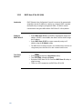
1
Agilent
Pulse Function Arbitrary
Noise Generator
81150A and 81160A
User’s Guide
Notices
© Agilent Technologies, Inc. 2011
No part of this manual may be reproduced in any
form or by any means (including electronic
storage and retrieval or translation into a foreign
language) without prior agreement and written
consent from Agilent Technologies, Inc. as
governed by United States and international
copyright laws.
Manual Part Number
81160-91020
Edition
First edition, March 2011
Printed in Germany
Agilent Technologies, Deutschland GmbH
Herrenberger Str. 130
71034 Böblingen, Germany
For Assistance and Support
Warranty
The material contained in this document is
provided “as is,” and is subject to being
changed, without notice, in future editions.
Further, to the maximum extent permitted by
applicable law, Agilent disclaims all warranties,
either express or implied, with regard to this
manual and any information contained herein,
including but not limited to the implied
warranties of merchantability and fitness for a
particular purpose. Agilent shall not be liable for
errors or for incidental or consequential
damages in connection with the furnishing, use,
or performance of this document or of any
information contained herein. Should Agilent and
the user have a separate written agreement with
warranty terms covering the material in this
document that conflict with these terms, the
warranty terms in the separate agreement shall
control.
Technology Licenses
The hardware and/or software described in this
document are furnished under a license and may
be used or copied only in accordance with the
terms of such license.
Restricted Rights Legend
If software is for use in the performance of a U.S.
Government prime contract or subcontract,
Software is delivered and licensed as
“Commercial computer software” as defined in
DFAR 252.227-7014 (June 1995), or as a
“commercial item” as defined in FAR 2.101(a) or
as “Restricted computer software” as defined in
FAR 52.227-19 (June 1987) or any equivalent
agency regulation or contract clause. Use,
duplication or disclosure of Software is subject to
Agilent Technologies‟ standard commercial
license terms, and non-DOD Departments and
Agencies of the U.S. Government will receive no
greater than Restricted Rights as defined in FAR
52.227-19(c)(1-2) (June 1987). U.S. Government
users will receive no greater than Limited Rights
as defined in FAR 52.227-14 (June 1987) or DFAR
252.227-7015 (b)(2) (November 1995), as
applicable in any technical data.
Safety Notices
CAUTION
A CAUTION notice denotes a hazard. It
calls attention to an operating
procedure, practice, or the like that, if
not correctly performed or adhered to,
could result in damage to the product
or loss of important data. Do not
proceed beyond a CAUTION notice until
the indicated conditions are fully
understood and met.
WARNING
A WARNING notice denotes a hazard.
It calls attention to an operating
procedure, practice, or the like that, if
not correctly performed or adhered to,
could result in personal injury or
death. Do not proceed beyond a
WARNING notice until the indicated
conditions are fully understood and
met.
The following general safety precautions
must be observed during all phases of
operation of this instrument. Failure to
comply with these precautions or with
specific warnings elsewhere in this manual
violates safety standards of design,
manufacture, and intended use of the
instrument.
Agilent Technologies Inc. assumes no
liability for the customer's failure to comply
with these requirements.
Before operation, review the instrument and
manual for safety markings and instructions.
You must follow these to ensure safe
operation and to maintain the instrument in
safe condition.
This product is a Safety Class 1 instrument
(provided with a protective earth terminal).
The protective features of this product may
be impaired if it is used in a manner not
specified in the operation instructions.
All Light Emitting Diodes (LEDs) used in this
product are Class 1 LEDs as per IEC 60825-1.
This instrument is intended for indoor use in
an installation category II, pollution degree 2
environment. It is designed to operate at a
maximum relative humidity of 95% and at
altitudes of up to 2000 meters.
Refer to the specifications tables for the ac
mains voltage requirements and ambient
operating temperature range.
Verify that all safety precautions are taken.
The power cable inlet of the instrument
serves as a device to disconnect from the
mains in case of hazard. The instrument
must be positioned so that the operator can
easily access the power cable inlet. When
the instrument is rack mounted the rack
must be provided with an easily accessible
mains switch.
To minimize shock hazard, the instrument
chassis and cover must be connected to an
electrical protective earth ground. The
instrument must be connected to the ac
power mains through a grounded power
cable, with the ground wire firmly connected
to an electrical ground (safety ground) at the
power outlet. Any interruption of the
protective (grounding) conductor or
disconnection of the protective earth
terminal will cause a potential shock hazard
that could result in personal injury.
Do not operate the instrument in the
presence of flammable gases or fumes.
Operating personnel must not remove
instrument covers. Component replacement
and internal adjustments must be made only
by qualified personnel.
Instruments that appear damaged or
defective should be made inoperative and
secured against unintended operation until
they can be repaired by qualified service
personnel.
Indicates warning or caution. If you see this
symbol on a product, you must refer to the
manuals for specific Warning or Caution
information to avoid personal injury or damage to
the product.
Notice for European Community: This product
complies with the relevant European legal
Directives: EMC Directive 89/336/EEC and Low
Voltage Directive 73/23/EEC.
Safety requirements for electrical equipment for
measurement, control, and laboratory use
CAN/CSA C22.2 No. 1010.1 (1993) UL 3101, 3111
(First Editions). This equipment has also been
evaluated to IEC 61010 edition 1 including
amendments 1 and 2.
Conformity Mark of the Australian ACA for EMC
compliance.
General Recycling Mark for plastic parts used in
the product.
This product complies with the WEEE
Directive (2002/96/EC) marketing
requirements. The affixed label indicates
that you must not discard this
electrical/electronic product in domestic
household waste.
Product category: With reference to the
equipment types in the WEEE Directive
Annexure I, this product is classed as a
“Monitoring and Control
instrumentation” product.
Do not dispose in domestic household
waste.
To return unwanted products, contact
your local Agilent office, or see
www.agilent.com/environment/product/
for more information.
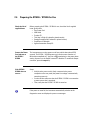
4
Contents
Contents ................................................................................................................................................................ 6
1
Introduction .......................................................................................................................................... 13
2
Front-Panel Menu Operation ............................................................................................................. 17
2.1
The Front Panel............................................................................................................................ 19
2.2
Help is Available .......................................................................................................................... 24
2.3
The Front-Panel Display at a Glance ........................................................................................ 25
2.3.1 Menu Mode ..................................................................................................................... 25
2.3.2 Graph Mode ..................................................................................................................... 26
2.4
The Front-Panel Number Entry ................................................................................................. 27
2.5
The Rear Panel ............................................................................................................................. 28
2.6
Preparing the 81150A / 81160A for Use ................................................................................. 30
2.7
Using the Built-in Help System ................................................................................................. 31
2.8
Selecting the Mode of Operation.............................................................................................. 32
2.9
Selecting Trigger Mode and Source ......................................................................................... 33
2.10
Selecting the Waveform ............................................................................................................. 37
2.11
Selecting the Advanced Mode .................................................................................................. 40
2.11.1 Modulation .................................................................................................................... 40
2.11.2 Burst ............................................................................................................................... 41
2.11.3 Sweep ............................................................................................................................. 42
2.12
Setting the Output Frequency ................................................................................................... 43
2.13
Setting the Output Amplitude ................................................................................................... 45
2.13.1 Converting the amplitude from one unit to another ............................................... 47
6
2.14
Selecting Delay ............................................................................................................................ 48
2.15
Selecting DC Volts....................................................................................................................... 50
2.16
Setting a DC Offset Voltage ....................................................................................................... 51
2.17
Setting the Duty Cycle of a Square Wave ............................................................................... 53
2.18
Setting the High-Level and Low-Level Values........................................................................ 54
2.19
Configuring a Pulse Waveform ................................................................................................. 55
2.20
Setting up a Pattern .................................................................................................................... 57
Contents
2.21
Viewing a Waveform Graph ....................................................................................................... 59
2.22
Outputting a Stored Arbitrary Waveform ................................................................................ 60
2.23
Selecting the Output Termination ............................................................................................ 62
2.24
Outputting a Modulated Waveform.......................................................................................... 64
2.25
Outputting an FSK Waveform .................................................................................................... 67
2.26
Outputting a PWM Waveform................................................................................................... 70
2.27
Outputting a Frequency Sweep ................................................................................................. 72
2.28
Outputting a Burst Waveform ................................................................................................... 75
2.29
Triggering a Sweep or Burst...................................................................................................... 78
2.30
Storing the Instrument State ..................................................................................................... 79
2.31
Configuring the Remote Interface ............................................................................................ 82
2.31.1 GPIB Configuration ...................................................................................................... 82
2.31.2 USB Configuration ........................................................................................................ 83
2.31.3 LAN Configuration........................................................................................................ 84
2.32
3
Resetting the 81150A / 81160A ............................................................................................... 89
Features and Functions ...................................................................................................................... 91
3.1
Trigger Mode ................................................................................................................................ 93
3.1.1 Arming Source ................................................................................................................ 95
3.1.2 Arming Slope ................................................................................................................... 97
3.1.3 Internal Trigger Period/Frequency .............................................................................. 98
3.2
Output Configuration ................................................................................................................ 100
3.2.1
3.2.2
3.2.3
3.2.4
3.2.5
3.2.6
3.2.7
3.2.8
3.2.9
3.2.10
3.2.11
3.2.12
3.2.13
81150A and 81160A User’s Guide
Output Function ............................................................................................................ 100
Output Frequency ......................................................................................................... 102
Output Amplitude ......................................................................................................... 105
DC Offset Voltage ......................................................................................................... 108
Output Units .................................................................................................................. 110
Load Impedance............................................................................................................ 111
Output Source Impedance .......................................................................................... 112
Voltage Autoranging .................................................................................................... 113
Amplifier Type Selection ............................................................................................. 114
Digital Channel Addition ........................................................................................... 115
Voltage Limits ............................................................................................................. 116
Duty Cycle (Square Waves) ...................................................................................... 117
Symmetry (Ramp Waves).......................................................................................... 119
7
3.2.14
3.2.15
3.2.16
3.2.17
3.2.18
3.2.19
3.3
Output Control............................................................................................................. 120
Parameter Coupling.................................................................................................... 121
Polarity ......................................................................................................................... 125
Strobe Output .............................................................................................................. 126
Trigger Output ............................................................................................................. 127
Sync Output ................................................................................................................. 128
Input Configuration ................................................................................................................... 130
3.3.1 External In Parameters ................................................................................................ 131
3.3.2 Modulation In Parameters .......................................................................................... 135
3.3.3 Reference Clock ............................................................................................................ 140
3.4
Pulse Waveforms ...................................................................................................................... 142
3.4.1 Pulse Period................................................................................................................... 143
3.4.2 Pulse Width ................................................................................................................... 144
3.4.3 Leading Edge/Trailing Edge ....................................................................................... 146
3.5
Pattern Capabilities ................................................................................................................... 149
3.5.1
3.5.2
3.5.3
3.5.4
3.5.5
3.5.6
3.5.7
3.5.8
Pattern Mode ................................................................................................................ 150
Pattern Source .............................................................................................................. 151
Configuring the External Pattern Source .................................................................. 153
Selecting a Pattern ....................................................................................................... 160
Creating, Editing and Storing a Pattern .................................................................... 162
Bitshape Selection ....................................................................................................... 169
Creating, Editing and Storing a Bitshape ................................................................. 171
Triggered and Gated Patterns .................................................................................... 177
3.6
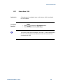
Noise............................................................................................................................................ 179
3.7
Amplitude Modulation (AM).................................................................................................... 181
3.7.1
3.7.2
3.7.3
3.7.4
3.7.5
3.7.6
3.7.7
3.7.8
3.8
Selecting AM Modulation ........................................................................................... 182
Carrier Waveform Shape ............................................................................................. 183
Carrier Frequency.......................................................................................................... 184
Modulating Waveform Shape..................................................................................... 185
Modulating Waveform Frequency ............................................................................. 186
Modulating Depth ......................................................................................................... 187
DSSC (Double Sideband Suppressed Carrier Mode) .............................................. 189
Modulating Source ....................................................................................................... 191
Frequency Modulation (FM) .................................................................................................... 192
3.8.1 Selecting FM Modulation ............................................................................................ 193
3.8.2 Carrier Waveform Shape ............................................................................................. 194
8
Contents
3.8.3
3.8.4
3.8.5
3.8.6
3.8.7
3.9
Phase Modulation (PM) ........................................................................................................... 200
3.9.1
3.9.2
3.9.3
3.9.4
3.9.5
3.9.6
3.9.7
3.10
Selecting FSK Modulation......................................................................................... 209
Carrier Waveform Shape ........................................................................................... 210
FSK Carrier Frequency ............................................................................................... 211
FSK “Hop” Frequency ................................................................................................ 212
FSK Rate ....................................................................................................................... 213
FSK Source .................................................................................................................. 214
Pulse Width Modulation (PWM) ............................................................................................ 215
3.11.1
3.11.2
3.11.3
3.11.4
3.11.5
3.11.6
3.11.7
3.11.8
3.12
Selecting PM Modulation ........................................................................................... 201
Carrier Waveform Shape ............................................................................................. 202
Carrier Frequency.......................................................................................................... 203
Modulating Waveform Shape..................................................................................... 204
Modulating Waveform Frequency ............................................................................. 205
Phase Deviation ............................................................................................................ 206
Modulating Source ....................................................................................................... 207
Frequency-Shift Keying (FSK) Modulation ............................................................................ 208
3.10.1
3.10.2
3.10.3
3.10.4
3.10.5
3.10.6
3.11
Carrier Frequency.......................................................................................................... 195
Modulating Waveform Shape..................................................................................... 196
Modulating Waveform Frequency ............................................................................. 197
Peak Frequency Deviation ........................................................................................... 198
Modulating Source ....................................................................................................... 199
Selecting PWM Modulation ..................................................................................... 216
Pulse Waveform ......................................................................................................... 217
Pulse Period ................................................................................................................ 218
Modulating Waveform Shape .................................................................................. 219
Modulating Waveform Frequency ........................................................................... 220
Width Deviation .......................................................................................................... 221
Duty Cycle Deviation .................................................................................................. 222
Modulating Source ..................................................................................................... 225
Frequency Sweep ...................................................................................................................... 226
3.12.1
3.12.2
3.12.3
3.12.4
3.12.5
3.12.6
3.12.7
81150A and 81160A User’s Guide
Selecting a Sweep ...................................................................................................... 228
Start Frequency and Stop Frequency ...................................................................... 229
Center Frequency and Frequency Span .................................................................. 230
Idle Frequency ............................................................................................................. 232
Sweep Type ................................................................................................................. 233
Sweep Time ................................................................................................................. 235
Marker Frequency ...................................................................................................... 236
9
3.12.8 Triggered/Gated Sweep ............................................................................................ 237
3.13
Burst Mode ................................................................................................................................. 239
3.13.1
3.13.2
3.13.3
3.13.4
3.13.5
3.13.6
3.14
Selecting a Burst ........................................................................................................ 240
Continuous Burst Mode ............................................................................................ 241
Triggered Burst Mode................................................................................................ 242
Gated Burst Mode ...................................................................................................... 243
Burst Count ................................................................................................................. 244
Burst Phase ................................................................................................................. 245
Arbitrary Waveforms ................................................................................................................. 246
3.14.1 Creating and Storing an Arbitrary Waveform ........................................................ 247
3.14.2 Managing Stored Waveforms .................................................................................. 254
3.14.3 Additional Information on Arbitrary Waveforms ................................................... 257
3.15
System-Related Operations ..................................................................................................... 258
3.15.1
3.15.2
3.15.3
3.15.4
3.15.5
3.15.6
3.15.7
3.15.8
3.15.9
3.15.10
3.16
Remote Interface Configuration .............................................................................................. 274
3.16.1
3.16.2
3.16.3
3.16.4
3.16.5
3.16.6
3.16.7
3.16.8
3.16.9
3.16.10
10
Instrument State Storage .......................................................................................... 259
Export/Import State ................................................................................................... 262
Error Conditions .......................................................................................................... 264
Beeper Control ............................................................................................................ 266
Display Brightness ..................................................................................................... 267
Display Control ............................................................................................................ 268
Time .............................................................................................................................. 270
Date............................................................................................................................... 271
Firmware Revision Query .......................................................................................... 272
SCPI Language Version Query ............................................................................... 273
GPIB Address .............................................................................................................. 275
DHCP/Auto-IP On/Off (LAN) ................................................................................... 276
IP Address (LAN)........................................................................................................ 277
Subnet Mask (LAN) ................................................................................................... 278
Default Gateway (LAN) ............................................................................................. 279
Host Name................................................................................................................... 280
Domain Name (LAN).................................................................................................. 281
DNS Server (LAN) ...................................................................................................... 282
WINS Server (LAN) .................................................................................................... 283
Current Configuration (LAN) .................................................................................. 285
3.17
Software Update ........................................................................................................................ 287
3.18
Installing Licenses..................................................................................................................... 289
Contents
4
3.19
Diagnostics/Calibration Overview .......................................................................................... 291
3.20
Security ....................................................................................................................................... 294
3.21
Factory Default Settings ........................................................................................................... 295
Remote Programming Reference .................................................................................................... 301
4.1
Agilent 81150A / 81160A Remote Control............................................................................ 301
4.1.1 Programming Recommendations............................................................................... 302
4.2
81150A / 81160A SCPI Command Summary ........................................................................ 304
4.3
Common Command Summary ................................................................................................. 317
4.4
81150A / 81160A SCPI Instrument Command List Format ................................................ 319
4.5
81150A / 81160A SCPI Instrument Elements Name .......................................................... 320
4.5.1
4.5.2
4.5.3
4.5.4
4.5.5
4.5.6
4.5.7
4.5.8
4.5.9
4.5.10
4.5.11
4.5.12
4.5.13
4.5.14
4.5.15
4.5.16
APPLy Commands ........................................................................................................ 321
Arbitrary Waveform Commands................................................................................. 331
Burst Commands .......................................................................................................... 354
Level Commands........................................................................................................... 363
Modulation Commands ............................................................................................... 373
Channel Command ....................................................................................................... 416
Output Commands........................................................................................................ 418
Output Function Commands ....................................................................................... 433
Reference Clock Commands ....................................................................................... 467
Non-Volatile Storage Commands ............................................................................ 470
Status Reporting Commands .................................................................................... 484
Sweep Commands...................................................................................................... 490
System-Related Commands...................................................................................... 501
Display Commands..................................................................................................... 522
Triggering Commands................................................................................................ 526
Pattern Related Commands ...................................................................................... 538
4.6
Common Command List ........................................................................................................... 575
4.7
Status Model .............................................................................................................................. 578
4.7.1
4.7.2
4.7.3
4.7.4
4.8
Status register structure ............................................................................................. 580
Status Byte Register .................................................................................................... 581
STATus Commands ...................................................................................................... 582
STATus Questionable Data Register command subsystem .................................. 582
Programming Basics ................................................................................................................. 585
4.8.1 Before you begin........................................................................................................... 585
4.8.2 Application Programs .................................................................................................. 589
81150A and 81160A User’s Guide
11
5
Error Messages ................................................................................................................................. 597
6
Application Programs ....................................................................................................................... 599
7
Tutorial ................................................................................................................................................ 601
7.1
Direct Digital Synthesis ............................................................................................................ 602
7.2
Creating Arbitrary Waveforms................................................................................................. 606
7.3
Pulse Waveform Generation.................................................................................................... 609
7.4
Pattern Generation .................................................................................................................... 611
7.4.1
7.4.2
7.4.3
7.4.4
7.4.5
7.5
Multi-Level Pattern Definitions .................................................................................. 612
Pattern Types and Sequencing Capabilities ............................................................ 614
Trigger Modes ............................................................................................................... 615
Defining the Shape of a Bit......................................................................................... 616
External Patterns .......................................................................................................... 620
Noise Generation ....................................................................................................................... 622
7.5.1 Limitations of User-defined Noise Distributions ..................................................... 624
A
7.6
Trigger Modes ............................................................................................................................ 626
7.7
External In to Trigger Out Timing ........................................................................................... 629
7.8
Signal Imperfections ................................................................................................................. 631
7.9
Output Amplitude Control ........................................................................................................ 633
7.10
Attributes of AC Signals ........................................................................................................... 636
7.11
Modulation.................................................................................................................................. 639
7.12
Frequency Sweep ...................................................................................................................... 646
7.13
Burst ............................................................................................................................................ 649
7.14
Channel Addition ....................................................................................................................... 651
7.15
Coupling between Channels .................................................................................................... 653
Appendix ............................................................................................................................................. 655
A.1
Coupled Parameters when channel coupling is on ............................................................. 655
A.2
Pulse Parameter Definitions .................................................................................................... 658
A.3
Agilent 81150A / 81160A in comparison with other Agilent instruments ...................... 665
A.3.1 Agilent 81110A/81104A/81101A instrument family ............................................. 665
A.3.2 Agilent 33220A ............................................................................................................. 667
A.4
12
Preparing a USB Flash Drive using Windows Vista® .......................................................... 670
1
Agilent
Technologies’
81150A / 81160A
Pulse Function
Arbitrary Noise
Generator
Features and
Benefits
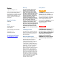
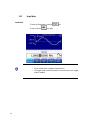
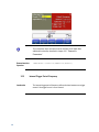
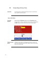
The Agilent Technologies 81150A and 81160A is a Pulse Pattern and
Function Arbitrary Noise Generator with built-in arbitrary waveform and
pulse capabilities
Its combination of bench-top and system features makes this Pulse Function
Arbitrary Noise Generator a versatile solution for your testing requirements
now and in the future.
Benchtop Testing
81150A and 81160A User’s Guide
Introduction
81150A: 1 Hz-120 MHz pulse generation with variable rise/fall time
81150A: 1 Hz-240 MHz sine waveform outputs
81160A: 1 Hz-330 MHz pulse generation with variable rise/fall time
81160A: 1 Hz-500 MHz sine waveform outputs
Pulse, sine, square, ramp, noise and arbitrary waveforms
FM, AM, PM, FSK, PWM modulation capability
One or two channels
81150A: 14-bit, 2GSa/s, 512 KSa deep arbitrary waveform memory
per channel
81160A: 14-bit, 2.5GSa/s, up to 256 KSa deep arbitrary waveform
memory per channel
USB, GPIB and LAN connectivity.
Glitch free change of timing parameters delay, frequency, transition
time, width, duty cycle
LXI class C compliant
The 81150A / 81160A features a graphic display showing all pulse
parameters at a glance. The cursor keys and the modify knob allow fast and
simple operation.
The user interface is designed to minimize the time invested in getting
familiar with the instrument. After familiarization, the instrument supports
quick setups of signals. This leaves you free to concentrate on the
measurement task and testing of the DUT.
13
What’s inside this
Manual
This manual provides detailed information about the following:
Front-Panel Menu Operation
Features and Functions
Remote Programming Reference
Error Messages
Application Programs
Tutorial
Purpose of this
Manual
The purpose of this manual is to enable you to install, initialize, and start the
81150A / 81160A and to understand the front-panel menu features of the
81150A / 81160A.
Who should read
this Manual
This manual is intended for testers and Engineers who will be using the
81150A / 81160A to test other devices.
How this document
is organized
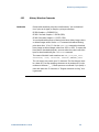
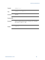
This section provides information on the chapters, and their content.
Navigating this manual
14
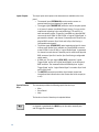
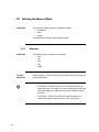
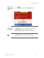
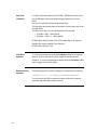
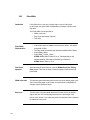
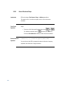
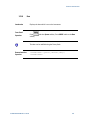
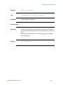
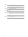
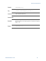
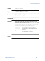
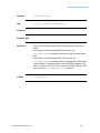
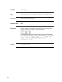
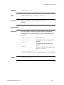
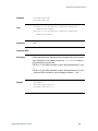
Topic
What information does it contain?
Introduction
Introduces the 81150A / 81160A, defines the purpose and
intended audience of this manual; explains how information is
organized in this manual.
Front-Panel Menu Operation
Introduces you to the Front-Panel Menu and describes some of
the menu features of the 81150A / 81160A Pulse Pattern and
Function Arbitrary Noise Generator.
Features and Functions
Gives a detailed description of the 81150A / 81160A‟s
capabilities and operation. You will find this section useful when
you are operating the 81150A / 81160A from the front panel or
over the remote interface.
Introduction
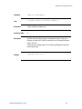
Topic
What information does it contain?
Remote Programming Reference Contains reference information to help you program the 81150A
/ 81160A over the remote interface.
Error Messages
Describes the error reporting model that is used by the 81150A /
81160A.
Application Programs
Describes the various types of programming examples available
for the 81150A / 81160A and where to find them.
Tutorial
Gives an overview of the internal operations of the 81150A /
81160A.
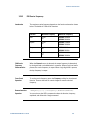
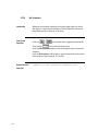
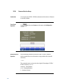
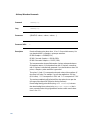
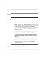
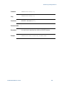
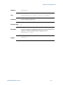
The following table lists the terms and conventions used in this manual:
Terms and
conventions used in
this manual
Conventions
The icon...
Indicates…
A note or important information.
A tip
A caution or warning
Acronyms used in
this manual
Notes within a table
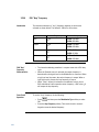
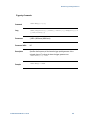
The following table lists the acronyms and abbreviations used in this manual:
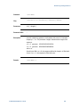
Acronyms used in this Document
Acronym
Explanation
DHCP
Dynamic Host Configuration Protocol
DNS
Domain Name Service
DUT
Device Under Test
81150A and 81160A User’s Guide
15
References
16
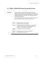
The Getting Started Guide along with this manual forms a part of the 81150A
and 81160A product documentation suite.
2
Introduction
81150A and 81160A User’s Guide
Front-Panel Menu Operation
This section introduces the front-panel menu and describes the menu
features of the 81150A / 81160A Pulse Pattern and Function Arbitrary Noise
Generator.
17
What’s inside this
Chapter
18
The following topics are discussed in this section:
The Front Panel
Help is Available
The Front-Panel Display at a Glance
Menu Mode
Graph Mode
The Front-Panel Number Entry
The Rear Panel
Preparing the 81150A / 81160A for Use
Using the Built-in Help System
Selecting the Mode of Operation
Selecting Trigger Mode
Selecting the Waveform
Selecting the Advanced Mode
Setting the Output Frequency
Setting the Output Amplitude
Selecting Delay
Selecting DC Volts
Setting a DC Offset Voltage
Setting the Duty Cycle of a Square Wave
Setting the High-Level and Low-Level Values
Configuring a Pulse Waveform
Setting up a Pattern
Viewing a Waveform Graph
Outputting a Stored Arbitrary Waveform
Selecting the Output Termination
Outputting a Modulated Waveform
Outputting an FSK Waveform
Outputting a PWM Waveform
Outputting a Frequency Sweep
Outputting a Burst Waveform
Triggering a Sweep or Burst
Storing the Instrument State
Configuring the Remote Interface
Resetting the 81150A / 81160A
Front-Panel Menu Operation
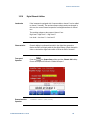
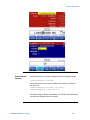
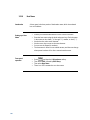
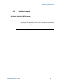
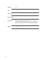
2.1
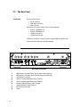
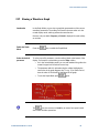
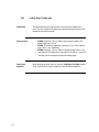
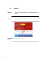
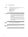
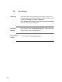
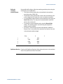
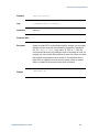
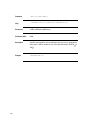
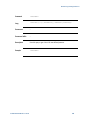
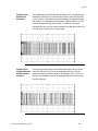
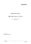
The Front Panel
Introduction
The instrument is mainly operated from the front panel, when used for
benchtop testing.
This section explains the Keys, Functions, Inputs/Outputs and Controls,
seen on the Front Panel of the 81150A / 81160A.
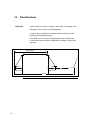
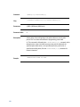
Channel 1 Selection
USB Host
Navigation
Keys
Channel Coupling
Rotary Knob Trigger
Cursor Keys Modes
Waveform Advanced
Type
Modes
Special
Function Keys
Channel 2 Selection
81150A
120 MHz
Pu lse Fu n ction Arbitrary Gen erator
7
Ch 1
8
5
4
Coupling
Cont
Pulse
Square
Mod
Store/
Recall
6
Trig
Sine
Ramp
Sweep
Utility
Gated
Noise
Arb
Burst
Help
Man
9
1
2
3
0
.
+/-
Ch 2
Graph
External In
L ocal
Trigger Out 2
Strobe Out 2
Out 2
Trigger Out 1
Out 2
Strobe Out 1
Out 1
Out 1
max. ±15V
Cancel
Power Switch
Menu Softkeys
Cancel
Numeric Keypad
Inputs / Outputs
Graph / Local
Front Panel of the 81150A
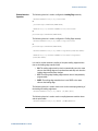
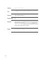
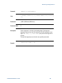
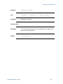
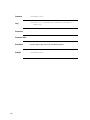
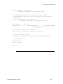
Channel 1 Selection
USB Host
Navigation
Keys
Channel Coupling
Rotary Knob
Cursor Keys
Trigger
Modes
Waveform Advanced
Special
Type
Modes
Function Keys
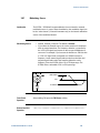
Channel 2 Selection
Ch1
Coupli ng
7
4
8
5
Cont
Pulse
Square
Mod
Store/
Recall
6
Trig
Sine
Ramp
Sweep
Utility
Gated
Noise
Arb
Burst
Help
Man
9
1
2
3
0
.
+/-
Ch2
Gr aph
Ext er nal
L ocal
m
a x .
I n
Out 2
Out 2
Sy nc
Ou t
A
Sy nc
Ou t
B
Out 1
Out 1
±1 0 V
Ca n c e l
Graph / Local
Power Switch
Menu Softkeys
Cancel
Numeric Keypad
Inputs / Outputs
Front Panel of the 81160A
81150A and 81160A User’s Guide
19
Power Switch
The front panel switch is used to switch on and off the instrument.
When the front panel switch is off, the instrument is in standby mode. The
instrument is disconnected from the AC line power only by disconnecting
the power cord.
USB
The Front Panel contains a USB host connector. It is intended to connect
USB drives to store instrument states and waveforms on an external
memory.
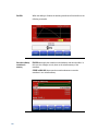
Menu Softkeys
The five keys below the main display screen are called softkeys (softwarecontrolled keys). The current function of each softkey is indicated in the
corresponding box on the display.
Some softkeys hold additional symbols to indicate that they provide
extended functionality.
Yellow Triangles:
These are visible on the five softkeys on the
Front Panel. The yellow triangles indicate that there are more choices
further, and keep pressing to view the available options.
White Rectangles:
Indicate that by pressing them, you can
enter into another screen.
The following examples explain the above-mentioned points:
Pressing this softkey will toggle between
Frequency and Period representation.
Pressing this softkey will open the output
configuration screen.
More Key
20
Pressing the MORE key switches to the next layer of softkeys on the current
screen.
Front-Panel Menu Operation
Pressing the Cancel key cancels the selection/input and helps you exit out
of a screen. But the functionality of exiting out of a screen is limited to a
few screens, like selecting an Arbitrary waveform.
The 81150A / 81160A consists of two channels and operates in two
different modes of operation:
Coupling off: The two channels operate entirely independent. Frequency
generation for both channels is based on same clock reference.
Coupling on: The frequency, trigger mode, waveform type and advanced
mode are identical for both channels. The delay between the channels is
specified.
A modulation input (for AM, FM, PM, FSK, PWM) for each channel is
provided on the back-panel. In the two channel version each channel can
modulate the other channel.
Refer to the Appendix for a list of all coupled parameters.
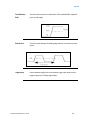
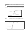
Press the Graph key to view a graphical representation of the waveform.
Press it again to exit from that mode.
Not every screen has a graphical representation, e.g. like the Trigger Mode
Screen.
Numeric Keypad,
Cursor Keys,
Rotary Knob
81150A and 81160A User’s Guide
These keys are used to select and modify parameters when operating the
instrument.
Use the numeric keypad to enter numbers and the menu softkeys to select
units.
Use the Rotary knob and cursor keys to modify the displayed number.
21
Inputs/Outputs
The major inputs and outputs of the instrument are available at the front
panel:
The external input (EXTERNAL IN) can be used to connect an
external arming source (triggered or gated modes).
The trigger signal (TRIGGER OUT) marks the start of the pulse period
or of parts of a pattern (see Mode/Trigger Screen.). You can set the
output levels according to the used technology (TTL and ECL) or
enter test-specific values. Trigger Out is available as a physical BNC
connector at the 81150A. For the 81160A, a „Logical Trigger Signal‟ is
generated for channel 1 and channel 2 internally and is routed to the
physical BNC connector Sync Out A and/or Sync Out B using a
configurable switch matrix.
The strobe signal (STROBE OUT) marks beginning and end of a burst
in Burst mode. Strobe Out is available as a physical BNC connector
at the 81150A. For the 81160A, a „Logical Strobe Signal‟ is generated
for channel one and channel 2 internally and is routed to the physical
BNC connector Sync Out A and/or Sync Out B using a configurable
switch matrix.
81160A only: The sync signal (SYNC OUT) outputs the „Logical
Trigger Signal‟ and/or the „Logical Strobe Signal‟ at the front panel
BNC connector. The instrument offers full flexibility how „Logical
Trigger Signal‟ and/or „Logical Strobe Signal‟ is routed to Sync Out A
and/or Sync Out B.
The OUTPUT connectors provide the signal output (normal and
inverted) and the indicators show the current state of the output (on
or off).
Special Function
Keys
The instrument provides the following special function keys:
Man
Store/Recall
Help
The function of each of these keys is explained below.
In triggered or gated mode, the MAN key can be used to manually arm
and/or trigger the instrument.
22
Front-Panel Menu Operation
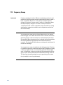
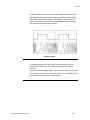
Trigger Modes
The trigger modes are explained below in subsequent sections:
Continuous
External Triggered
External Gated
Internal Triggered
Manual
See Selecting Trigger Mode section for more details.
Waveform Types
The standard waveforms include: Pulse, Sine, Noise, Square, Ramp and
Arbitrary.
The predefined arbitrary waveforms include: Exponential rise, exponential
fall, sin(x)/x, cardiac, gaussian, haversine, negative ramp, and DC.
Advanced modes of
Operation
There are three advanced modes of operation available:
Modulation: Selects the modulation type from AM, FM, PM, FSK,
PWM.
Sweep: For frequency sweeps.
Burst: Repeats selected waveform n times.
The following sections provide more details on the modulation types.
The Store/Recall key can be used to store to/recall from 1 to 4 individual
settings in the instrument memory. In the internal memory location 0 there
is a default setting stored.
The Utility key enables you to enable/disable DC mode, change the Output
Setup, and also contains information about the I/O Interfaces and the
system settings of the 81150A / 81160A.
The Help key provides access to the instrument‟s integrated help or in
warning or error state, access to Warning/Error Report screen.
81150A and 81160A User’s Guide
23
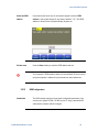
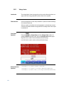
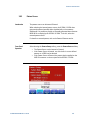
2.2
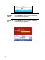
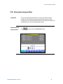
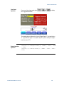
Help is Available
Introduction
Whenever you are in doubt or the instrument signals warnings or errors,
press the Help key.
Pressing the Help key opens the „Main Help Page‟.
This main help page is the table of contents of the integrated help system
which lists all the help topics. You can obtain information by selecting the
corresponding link and then by pressing the Follow Link softkey.
24
Warnings and
Errors
If there are warnings or errors pending (indicated by a flushing W or E on
the screen), pressing the Help key displays a list of the current messages.
Using the Error Queue and Warning softkeys, you can toggle between both
lists. For more information on warnings and errors, see Warnings and Errors.
Exit Help
To exit Help, press the Help key again, or press any other parameter screen
key, e.g. Pulse, Sine, etc.
Front-Panel Menu Operation
2.3
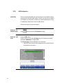
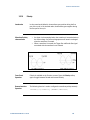
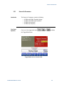
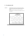
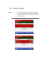
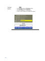
The Front-Panel Display at a Glance
Introduction
2.3.1
This section explains the Menu and the Graph mode as seen on the Front
Panel of the 81150A / 81160A.
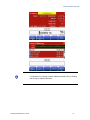
Menu Mode
Introduction
This section explains the Menu as seen on the Front Panel of the 81150A /
81160A.
Channel Information
Channel 1 Information
(Channel addition)
Channel 2 Information
(Frequency Coupling)
Trigger Information for
Channel 1 and 2
Numeric Readout
Units
Softkey Labels
81150A and 81160A User’s Guide
25
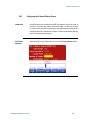
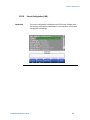
2.3.2
Introduction
Graph Mode
To enter the Graph mode, press the
To exit, press the
26
key.
key again.
Not all screens have a graphical representation.
The trigger mode screen will always be in textual mode, even if graph
mode is enabled.
Front-Panel Menu Operation
2.4
The Front-Panel Number Entry
Entering/modifying
numbers
You can enter numbers or modify the displayed number from the front-panel
using one of the following two methods:
Rotary Knob + Arrow Keys
Numeric keypad + softkeys
For selecting units
Use the numeric keypad and menu softkeys to select the units.
81150A and 81160A User’s Guide
The left/right arrows below the Rotary Knob are used to move left
and right to select the digit to be modified on a given screen.
When setting the cursor to the „exponent field‟ the exponent can be
changed via the Rotary Knob (only if the resulting number does fall
within the allowed range)
The cursor position is remembered when the cursor is placed on the
leftmost digit and the value is decreased from 1 to 0. In this case the
cursor changes it‟s color to green for some seconds and the cursor
position will be set back to the previous one when incrementing the
value again. For example, select the frequency to be edited and set
the cursor to the leftmost digit and then decrement the value by
turning the Rotary Knob counter clockwise. The cursor will move one
digit to the right when the digit would go from 1 to 0 and changes it‟s
color to green. When incrementing while the cursor is green, it will
jump back to the initial digit when crossing the 0 to 1 border.
The left arrow key can be used to delete the digit left to the input
cursor when entering values with the numeric keypad.
27
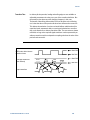
2.5
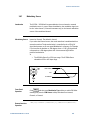
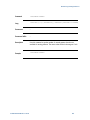
The Rear Panel
Introduction
The rear panel contains:
GP-IB connector
USB device connector
LAN connector
These three are used for remote control of the instrument.
Channel 1 Modulation In
Channel 2 Modulation In
10 MHz Clock Ref-In
10 MHz Clock Ref-Out
A USB Host Connector is used to connect external USB storage device for
storing instrument settings or software updates.
1
2
3
4
5
6
7
8
Rear panel of the 81150A
1
2
3
4
5
6
7
8
9
28
USB Interface Connector (Host type for external mass memory)
USB Interface Connector (device type for remote programming)
LAN Interface Connector
Channel 1 External Modulation Input Terminal
Channel 2 External Modulation Input Terminal
External 10 MHz Reference Input Terminal
10 MHz Reference output Terminal
GPIB Interface Connector
Power
9
Front-Panel Menu Operation
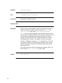
1
1 0 M
Hz
2
4
3
5
R e f 1 0OM uHt z
Re f M
I n o d u l a t i oMn o Id nu l 1a t i o n I n
m a x . 5 V
m a x . 5 V
m a x .
1 Vp p
r m s
r m s
±1 0 V
4 2 pV k
1 0 pV k
2
6
7
L AN
8
9
2 0 0 - VA
2 4C 0 5 0 - 6 0 H z
1 8 0 W
m a x .
1 0 0 - VA
1 2C7 5 0 - 4 0 0 H z
1 8 0 W
m a x .
G PI B
1 0 pVk
Rear panel of the 81160A
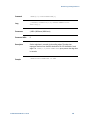
1
2
3
4
5
6
7
8
9
10 MHz Reference Output Terminal
External 10 MHz Reference Input Terminal
Channel 1 External Modulation Input Terminal
Channel 2 External Modulation Input Terminal
USB Interface Connector (Host type for external mass memory)
USB Interface Connector (device type for remote programming)
LAN Interface Connector
GPIB Interface Connector
Power
81150A and 81160A User’s Guide
29
2.6
Preparing the 81150A / 81160A for Use
Check the List of
supplied items
Before preparing the 81150A / 81160A for use, check the list of supplied
items, given below:
One Power Cord
USB Cable
Product CD
This User‟s Guide (if ordered in printed version)
Getting Started Guide (if ordered in printed version)
Certificate of Calibration
Agilent Automation Ready CD
Connect the Power
Cord and turn on
the 81150A /
81160A
The instrument runs a short power-on self test, which takes about 45-50
seconds. The 81150A / 81160A powers up in the sine wave function at 1
MHz with an amplitude of 1 Vpp (into a 50 termination) or the power-down
setting. At power-on, the Output connector is disabled. To enable the Output
connector, press the output key.
If the 81150A /
81160A does not
turn on….
Steps:
Verify that the power cord is firmly connected to the power
receptacle on the rear panel (the power-line voltage is automatically
sensed at power-on).
You should also make sure that the 81150A / 81160A is connected to
a power source that is energized.
Then, verify that the 81150A / 81160A is turned on.
If the power-on tests fail, the instrument automatically switches to the
diagnostics screen and displays the power on messages.
30
Front-Panel Menu Operation
2.7
Using the Built-in Help System
Introduction
The built-in help system is designed to provide context-sensitive assistance
on any front-panel key or menu softkey. A list of help topics is also available
to assist you with several front-panel operations.
To view the help
information for a
function key
Steps:
Press and hold down the key. If the message contains more
information than will fit on the display, press the up/down keys or
turn the knob to view the remaining information.
Press the Help key to exit Help.
To view the list of
topics
Steps:
Press the Help key to view the list of available help topics.
To scroll through the list, press the up/down arrow keys or rotate the
knob. Select any topic using the Previous Link and Next Link keys,
and press Follow link to obtain details on the selected topic.
Press the Help key to exit Help.
To view the help
information for
displayed
messages
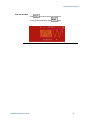
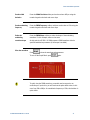
Whenever a limit is exceeded or any other invalid configuration is found, the
81150A / 81160A will display a message. For example, if you enter a value
that exceeds the frequency limit for the selected function, a message will be
displayed. The built-in help system shows all active messages.
Steps:
Press the Help key. Upon doing this, you will see an error or warning
is active (red or yellow text scrolling on the display and a red E or
orange W indicator blinking in the input line). The instrument will
automatically switch to the error or warning screen.
Press the Help key to exit Help.
81150A and 81160A User’s Guide
31
2.8
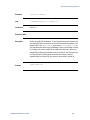
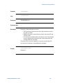
Selecting the Mode of Operation
Introduction
The Mode of operation consists of the following four components:
Coupling between Ch1 & Ch2
Trigger Mode
Waveform Type
Advanced Modes
These are further explained below:
Coupling between
Ch1 & Ch2
There are two output channels available for the Agilent 81150A / 81160A.
The 2 channel version operates in two different modes of operation:
Coupling off: The two channels operate entirely independent. Frequency
generation for both channels is based on the same clock reference.
Coupling on: The frequency, trigger mode, waveform type and advanced
mode are identical for both channels. The delay between the channels is
specified.
Refer to the Appendix for a list of all coupled parameters.
The Trigger Mode, Waveform Type and the Advanced Modes are explained
in the following sections.
32
Front-Panel Menu Operation
2.9
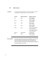
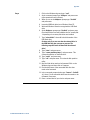
Selecting Trigger Mode and Source
Introduction
The source of a trigger event can be Internal, External, or Manual. The
default is External.
The following trigger modes are explained below:
Continuous
External Triggered
External Gated
Internal Triggered
Manual
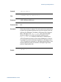
The following table explains the functionality of the 81150A / 81160A.
81150A and 81160A User’s Guide
33
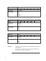
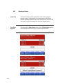
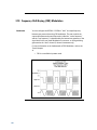
Trigger Mode
Continuous
Function
Pulse
Arming Source
Not Applicable
Advanced Mode
None
Burst
Sweep
Modulation
Trigger Mode
Triggered
Function
Pulse
Arming Source
MAN Key
External-In
Internal
Advanced Mode
None
Burst
Sweep
Trigger Mode
Gated
Function
Pulse
Arming Source
MAN Key
External-In
Advanced Mode
None
Burst
Sweep
Continuous
34
Square
Square
Square
Sine
Ramp
Noise
Arb
Sine
Ramp
Noise
Arb
Sine
Ramp
Noise
Arb
DC
Continuous starts the next waveform cycle immediately after the previous
one has finished.
This is used for a continuous waveform, burst, sweep or modulation. The
external input is not used in continuous mode.
Front-Panel Menu Operation
External Triggered
Triggered generates exactly one „signal‟ when the trigger condition is met
In the external trigger mode, the 81150A / 81160A will accept a hardware
trigger applied to the front-panel External In connector. The 81150A /
81160A initiates one sweep or outputs one burst each time External In
receives a pulse with the specified edge.
To select the external source, follow these steps:
Press the
key on the front panel.
Press Source softkey to select External In as the source. Upon
pressing the Source softkey while the highlight is on the trigger
source, the instrument allows you to choose one of the available
trigger sources. The value can also be changed by turning the Rotary
Knob.
To specify whether the 81150A / 81160A triggers on the rising or falling
edge, follow these steps:
Press the
key on the front panel.
Select the desired edge by pressing the Ext-In Sense softkey.
Change the value either by pressing the softkey or by turning the
knob.
External Gated
Gated starts the generation of „signals‟ as long as the gate is active.
The active level (high or low) at External In enables waveforms, bursts or
sweeps. The last waveform, burst or sweep is always completed.
Internal Triggered
In internal triggered mode, the instrument triggers a single waveform cycle,
sweep or burst at an adjustable trigger rate.
E.g. generate a pulse every 250ms
This mode is enabled by pressing the
key on the front panel and
then setting source to Internal. As soon as Source is set to Internal, the
trigger frequency/period can be adjusted by navigating to Int Freq or Int.
Period (depends on which of the two is currently active). Switching between
Int Freq and Int Period is done by navigating to the internal trigger
frequency/period and then pressing the corresponding softkey.
81150A and 81160A User’s Guide
35
Manual
In the manual trigger mode, you can manually trigger the 81150A / 81160A
by pressing the front panel
key. The 81150A / 81160A initiates one
waveform cycle, sweep or outputs one burst for each time you press or
release the key. The
key is illuminated while the 81150A / 81160A is
waiting for a manual trigger.
Front Panel
Operation
36
To set the Trigger Mode, do the following:
Press the corresponding key on the Front-Panel.
For selecting the arming source, press the Front panel key for the
desired trigger mode, press the Source softkey or navigate to Source
using the navigation keys.
Then change the selection.
Front-Panel Menu Operation
2.10 Selecting the Waveform
Introduction
The 81150A / 81160A can output six standard waveforms including:
Pulse
Sine
Square
Ramp
Noise
Arbitrary
You can also select one of the seven built-in arbitrary waveforms or create
your own custom waveforms.
You can internally modulate any of the standard waveforms (except pulse
and noise and DC) and also arbitrary waveforms using AM, FM, PM or FSK.
Pulse Waveform
Characteristics
A pulse is defined by the following parameters:
Amplitude/Offset or High-Level/Low-Level
Period or Frequency (not applicable for triggered pulses)
Width in seconds or Duty Cycle or Trailing delay in seconds
Delay in seconds
Delay as percentage of the period (not applicable for triggered
pulses)
Delay as phase in degree (not applicable for triggered pulses)
Leading edge transition time in seconds
Leading edge transition time in percent of width
Trailing edge transition time in seconds
Trailing edge transition time in percent of width
Polarity
Source Impedance
Load Impedance
81150A and 81160A User’s Guide
37
Pattern
Characteristics
Patterns are defined by the following parameters:
Internal or external pattern source
PRBS patterns and user defined patterns
NRZ formatting and Arbitrary Bit Waveform
Pattern Mode - On/Off
Patterns are also characterized by 2, 3 or 4 different levels per bit
Adjustable loop offset, allowing emulation of initialization preamble
and looped test pattern
External pattern source allows re-timing and re-shaping of externally
provided data stream
Sine Wave
Characteristics
A sine wave is defined by the following parameters:
Amplitude/Offset or High/Low Level
Period or Frequency
Delay in seconds
Delay in percent of period
Delay as phase in degree
Polarity
Source Impedance
Load Impedance
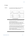
Square Wave
Characteristics
A square wave is defined by the following parameters:
Amplitude/Offset or High-Level/Low-Level
Period or Frequency
Duty Cycle
Delay in seconds
Delay as percentage of the period
Delay as phase in degree
Polarity
Source Impedance
Load Impedance
The instrument will always generate the fastest possible transition times
when generating square waves.
38
Front-Panel Menu Operation
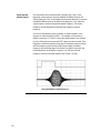
Ramp Wave
Characteristics
A ramp is defined by the following parameters:
Amplitude/Offset or High/Low Level
Period or Frequency
Delay in seconds
Delay in percent of period
Delay as phase in degree
Symmetry point in percent of period.
Polarity
Source Impedance
Load Impedance
Noise Wave
Characteristics
Noise is defined by the following parameters:
Amplitude/Offset or High/Low Level
Probability Density Function (PDF)
Source Impedance
Load Impedance
Arbitrary Wave
Characteristics
Arbitrary waveforms are defined by the following parameters:
Amplitude/Offset or High/Low Level
Period or Frequency
Delay in seconds
Delay in percent of period
Delay as phase in degree
Source Impedance
Load Impedance
81150A: Arbitrary waveforms can have up to 512k samples. The local
waveform editor allows to create and edit waveforms with up to 16k
samples.
81160A: Arbitrary waveforms can have up to 256k samples (1 channel) /
128k samples (2 channels). The local waveform editor allows to create and
edit waveforms with up to 16k samples.
81150A and 81160A User’s Guide
39
2.11 Selecting the Advanced Mode
Introduction
2.11.1
There are three advanced modes of operation available:
Modulation
Burst
Sweep
These advanced modes are further explained below.
Modulation
Introduction
The following types of modulation are available:
AM
FM
PM
FSK
PWM
To select
Modulation
Refer to Chapter 3, Features and Functions to understand how to select any
of these modulations.
40
The 81150A / 81160A will allow only one modulation mode to be
enabled at a time. For example, you cannot enable AM and FM at the
same time. When you enable AM, the previous modulation mode is
turned off.
The 81150A / 81160A will not allow any advanced mode to be
enabled with another advanced mode on the same channel.
Front-Panel Menu Operation
2.11.2
Burst
Introduction
You can configure the 81150A / 81160A to output a waveform with a
specified number of pulses/waveform cycles, called a burst. You can output
the burst at a rate determined by the internal rate generator or the signal
level on the Front Panel External In connector.
A burst can be initiated either by:
An Internal Immediate event, which triggers a continuous burst.
A trigger source, which triggers a triggered burst.
An active gate, which enables a gated burst.
Select the function
and amplitude for
the burst
For burst waveforms, you can select sine, square, ramp, pulse, or arbitrary
waveforms.
Burst mode cannot be used when using DC or noise.
Select the burst
mode
81150A and 81160A User’s Guide
Press
and specify the #Cycles and the Start Phase softkeys
to set the desired values.
The Start Phase defines the phase at which signal generation starts.
The allowed range is -360 to +360 . It is only applicable to Sine and
Arb waveforms.
Refer to Outputting a Burst Waveform for details.
41
2.11.3
Sweep
Introduction
To select a Sweep
In the frequency sweep mode, the 81150A / 81160A “steps” from the start
frequency to the stop frequency at a sweep rate which you specify.
The 81150A / 81160A can produce a frequency sweep for sine, square,
ramp, or arbitrary waveforms (pulse, noise, and dc are not allowed).
Press
to output a sweep using the present settings for frequency,
output amplitude, and offset. Enable sweep before setting up any of the
other sweep parameters.
The 81150A / 81160A will not allow the sweep mode to be enabled at the
same time when burst or any modulation mode is enabled. When you enable
sweep, the burst or modulation mode is turned off.
42
Front-Panel Menu Operation
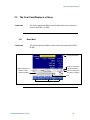
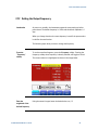
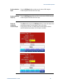
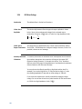
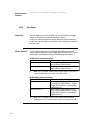
2.12 Setting the Output Frequency
Introduction
At power-on, normally, the instrument outputs the same setting as before
power-down. The default frequency is 1 MHz and the default amplitude is 1
Vpp.
When you change functions, the same frequency is used if the present value
is valid for the new function.
The following steps show you how to change the frequency.
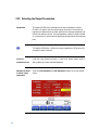
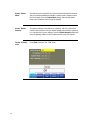
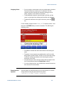
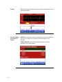
Press the
“Frequency”
softkey
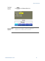
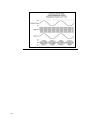
To set the waveform frequency, press the Frequency softkey. Pressing the
frequency softkey when Frequency is already selected, will toggle to Period.
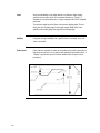
The current selection is highlighted as shown in the image below.
Enter the
magnitude of the
desired frequency
Using the numeric keypad, enter the desired value, say 1.2
81150A and 81160A User’s Guide
43
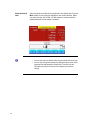
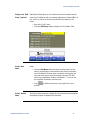
Select the desired
units
Select and press the softkey that corresponds to the desired units. Press the
More softkey to view more units available for the current selection. When
you select the units, the 81150A / 81160A outputs a waveform with the
displayed frequency (if the output is enabled).
44
You can also enter the desired value using the knob and cursor keys.
You can also change the exponent by setting the input cursor to the
exponent field and turning the Rotary Knob. To do this, use the
left/right key to place the cursor on the exponent you wish to
change.
Front-Panel Menu Operation
2.13 Setting the Output Amplitude
Introduction
At power-on, normally, the instrument outputs the same setting as before
power-down.
When you change functions, the same amplitude is used if the present value
is valid for the new function.
The following steps show you how to change the amplitude:
Press the “Ampl”
softkey
81150A and 81160A User’s Guide
To set the amplitude using a high level and low level, press the Ampl
softkey.
This will offer the level representations and units that can be chosen
for the output levels.
Choose the appropriate option from the given choices.
Press More to go to the units screen. Choose from the given units, by
pressing that unit itself.
45
46
Enter the
magnitude of the
desired amplitude
Using the numeric keypad, enter the desired value.
Select the desired
units
Select and press the softkey that corresponds to the desired units. When
you select the units, the 81150A / 81160A outputs a waveform with the
displayed amplitude (if the output is enabled). For this example, press mVrms.
Front-Panel Menu Operation
2.13.1
Converting the amplitude from one unit to another
Introduction
You can easily convert the displayed amplitude from one unit to another.
For example, the following steps show you how to convert the amplitude
from Vrms to Vpp.
Enter the numeric
entry mode
To switch between different representations, press the amplitude, offset,
high level, low level softkey and then choose the different representation.
You can choose between High/Low, Ampl/Offs.
Select the new
units
Steps:
Press Ampl softkey and then press the MORE softkey.
This brings you to another menu layer where you can choose
between Vpp/Vdc, Vrms/Vdc, dBm/Vdc that will be used when
Ampl/Offs is selected. The same softkey menu provides easy
application of TTL and ECL level settings.
81150A and 81160A User’s Guide
47
2.14 Selecting Delay
48
Introduction
The time between the start of a period until the start of the waveform is
called the delay. The start of a period is defined when the delay is set to 0ns.
It can be measured between the Trigger Out and Out Connector.
Delay Format
Delay has the following format:
Abs. Delay
% of Period
Phase
To select Delay
Steps:
Press the Delay softkey.
This will show the available choices for the delay format.
Front-Panel Menu Operation
Abs. Delay
Defines the time between the start of a period until the start of the
waveform in units of seconds.
% of Per
Defines the time between the start of a period till the start of the waveform
as a percentage of the period.
Phase
Defines the time between the start of a period till the start of the waveform
in degrees (1/360 of the period).
Selecting any of the delay formats will take you back to the main screen.
81150A and 81160A User’s Guide
49
2.15 Selecting DC Volts
Introduction
You can select the "DC Volts" feature from the “Utility” menu, and then set
a constant dc voltage as an "Offset" value. As an example, let us set "DC
Volts" = -1.5 Vdc.
To select DC Volts
Steps:
50
Press
and then press the DC Mode softkey.
Press the DC softkey to toggle between DC mode off and on. When
DC mode is being turned off, then the instrument will switch back to
the parameter screen of the waveform being generated.
Front-Panel Menu Operation
2.16 Setting a DC Offset Voltage
Introduction
At power-on, normally, the instrument outputs the same setting as before
power-down.
The following steps show you how to change the offset.
Press the “Offset”
softkey
Steps:
Press the Offset softkey to select the DC offset voltage. Enter the
desired voltage level as an “Offset” (as shown in the image below)
When you change functions, the same offset is used if the present value is
valid for the new function.
Enter the
magnitude of the
desired offset
81150A and 81160A User’s Guide
Using the numeric keypad, enter the value “-1.5” (as shown in the image
below).
51
Select the desired
units
52
Select and press the softkey that corresponds to the desired units. You can
choose from mVdc or Vdc. When you select the units, the 81150A / 81160A
outputs the waveform with the displayed offset (if the output is enabled).
For this example, press Vdc.
Front-Panel Menu Operation
2.17 Setting the Duty Cycle of a Square Wave
Introduction
At power-on, normally, the instrument outputs the same setting as before
power-down.
The duty cycle is limited by the minimum pulse width of Wmin.
This means the duty cycle can get as low as (100% * Wmin/period) and as
high as (100% * (1 –Wmin/period))
81150A: Where Wmin is either 4.1ns or 10ns depending on the selected
amplifier (See section Amplifier Type Selection).
81160A: Where Wmin is 1.5ns.
The following steps show you how to change the duty cycle to 30%.
Select the square
wave function
Press the
key and then set the desired output frequency to any value
up to 120 MHz for the 81150A (330 MHz for the 81160A).
Press the “Duty
Cycle” softkey
The duty cycle represents the amount of time per cycle that the square
wave is at a high level.
Enter the desired
duty cycle
Using the numeric keypad or the knob, select a duty cycle value of “30”. The
81150A / 81160A adjusts the duty cycle immediately and outputs a square
wave with the specified value (if the output is enabled).
81150A and 81160A User’s Guide
53
2.18 Setting the High-Level and Low-Level Values
Introduction
You can specify a signal by setting its amplitude and dc offset values.
Another way to set the limits of a signal is to specify its high-level
(maximum) and low-level (minimum) values. This is typically convenient for
digital applications.
In the following example, let us set the high-level to 1.0 V and the low-level
to 0.0 V.
To Set the HighLevel and LowLevel Values
Steps:
Press the Ampl softkey to select Ampl.
Press the softkey again to toggle to show the different
representations of the output voltages.
Press the High Low softkey to select High level and Low level
Both the Ampl and Offset softkeys toggle together, to High and Low,
respectively.
Set the High Level value using the numeric keypad or the knob.
Press the Low Level softkey and set the value using the numeric
keypad or the knob.
These settings (high-level = "1.0 V" and low-level = "0.0 V") are equivalent
to setting an amplitude of "1.0 Vpp" and an offset of "500 mVdc".
54
Front-Panel Menu Operation
2.19 Configuring a Pulse Waveform
Introduction
Select the pulse
function
Set the pulse
period
81150A and 81160A User’s Guide
You can configure the 81150A / 81160A to output a pulse waveform with
variable pulse width and edge time.
The following steps show you how to configure a 500 ms pulse waveform
with a pulse width of 10 ms and edge times of 50 ns.
Pulses do not have period/frequency when being triggered and burst is off.
In all other cases, a pulse does have a period/frequency like other
waveforms.
Press the
key to select the pulse function and output a pulse
waveform with the default parameters. This is only true if the instrument is
currently using the default setting.
Press the Frequency softkey to toggle to Period. Set the Pulse period to 500
ms.
55
56
Set the pulse width
Press the Width softkey and then set the pulse width to 10 ms. The pulse
width represents the start of leading edge to start of trailing edge.
Set the edge time
for both edges
Press the Lead Edge and Trail Edge softkeys and then set the edge time for
both the rising and falling edges to 50 ns. The edge time represents the time
from the 10% threshold to the 90% threshold of each edge.
Front-Panel Menu Operation
2.20 Setting up a Pattern
Introduction
Press the “Pattern
Setup” key
The pattern functionality can be accessed on the local user interface
through the Pattern Setup key on the pulse screen.
Press the
key to select the Pulse function.
Press the Pattern Setup softkey shown in the image below.
81150A and 81160A User’s Guide
This will show the Pattern Setup screen as shown in the following
image.
57
Pattern Mode
58
Press the Select Pattern softkey to select from the available built-in
PRBS patterns or user defined patterns.
Use the Rotary Knob or up/down Arrow keys to select.
Front-Panel Menu Operation
2.21 Viewing a Waveform Graph
Introduction
Enable the Graph
Mode
Select the desired
parameter
In the Graph Mode, you can view a graphical representation of the current
waveform parameters. The softkeys are listed in the same order as in the
normal display mode, and they perform the same function.
However, only one label, Frequency or Period is displayed for each softkey
at one time.
Press the
key to enable the Graph Mode.
To select a specific parameter, note the softkey labels at the bottom of the
display. For example, to select delay, press the Delay softkey.
As in the normal display mode, you can edit numbers using either the
numeric keypad or the knob and cursor keys.
The parameter which is selected using the softkey highlights the
same value in the graph diagram also. For e.g., if you select Period,
then the value of Period will be highlighted in the graph.
To exit the Graph Mode, press
again.
The
key also serves as a Local key to restore front-panel control
after remote interface operations.
81150A and 81160A User’s Guide
59
2.22 Outputting a Stored Arbitrary Waveform
Introduction
Select the arbitrary
waveform function
Select the active
waveform
There are seven built-in arbitrary waveforms stored in the non-volatile
memory.
The following steps show you how to output the built-in “exponential fall”
waveform from the front panel.
When you press the
key to select the arbitrary waveform function,
the 81150A / 81160A displays the currently used waveform in the textual
screens indicating which waveform is currently selected (the default is
“exponential rise”).
Steps:
Press the MORE softkey twice.
This brings you to a screen which has Select Waveform softkey on
it.
Press the Select Waveform softkey and select from the given
options. Choose the desired waveform and press select. Confirm your
choice by pressing Yes.
The 81150A / 81160A has a graphical browser to select the waveform to be
used. This waveform can either be a predefined one, or a user defined one
(from VOLATILE memory or a stored waveform from NON-VOLATILE
memory). It is also possible to import a waveform from a USB stick into
VOLATILE memory.
60
Front-Panel Menu Operation
For information on creating a custom arbitrary waveform, refer to Creating
and Storing an Arbitrary Waveform.
81150A and 81160A User’s Guide
61
2.23 Selecting the Output Termination
Introduction
The Agilent 81150A has a selectable series output impedance of either
50 ohms or 5 ohms to the front-panel output connector. If the actual load
impedance is different than the value specified, the displayed amplitude and
offset levels will be incorrect. The load impedance setting is simply provided
as a convenience to ensure that the displayed voltage matches the expected
load.
The Agilent 81160A has a fixed series output impedance of 50 ohms to the
front-panel output connector.
62
Press any
waveform screen
Press any of the waveform screens, i.e. Pulse, Sine, Square, Ramp, Noise or
Arb to adjust the output and load impedance.
Navigate the menu
to set the output
termination
Press the Load Impedance and Out Impedance softkeys to set the desired
values.
Front-Panel Menu Operation
Select the output
amplifier type and
ranging
Select Amplifier
Type and Range
Press the
key and then select the Output Setup softkey.
For Amplifier Type, choose from max Amplitude or max Bandwidth.
For Amplifier Range, choose from Hold, Auto or Auto Once.
Refer to the Amplifier Type Selection section for more information.
The Amplifier Type selection is available for the 81150A, only.
81150A and 81160A User’s Guide
63
2.24 Outputting a Modulated Waveform
Introduction
Select the function,
frequency, and
amplitude of the
carrier
Select AM
64
A modulated waveform consists of a carrier and a modulating waveform. In
AM (amplitude modulation), the amplitude of the carrier is varied by the
amplitude of the modulating waveform.
For this example, you will output an AM waveform with 80% modulation
depth. The carrier will be a 5 kHz sine wave and the modulating waveform
will be a 200 Hz sine wave.
Press
and then press the Frequency, Ampl, and Offset softkeys to
configure the carrier waveform. For this example, select a 5 kHz sine wave
with an amplitude of 5 Vpp.
Press
and then select “AM” using the Type softkey. Notice that a
status message “AM by Sine” is shown in the status line. The status line is
located between the parameters section of the screen and the input field.
Front-Panel Menu Operation
Set the modulation
depth
Press the AM Depth softkey and then set the value to 80% using the
numeric keypad or the knob and cursor keys.
Set the modulating
frequency
Press the AM Frequency softkey and then set the value to 200 Hz using the
numeric keypad or the knob and cursor keys.
Select the
modulating
waveform shape
Press More and then press the AM Shape softkey to select the shape of the
modulating waveform. For this example, select a sine wave.
At this point, the 81150A / 81160A outputs an AM waveform with the
specified modulation parameters (if the output is enabled).
81150A and 81160A User’s Guide
65
View the waveform
Press
to view the waveform parameters.
To turn off the Graph Mode, press
66
again.
Front-Panel Menu Operation
2.25 Outputting an FSK Waveform
Introduction
Select the function,
frequency, and
amplitude of the
carrier
Select FSK
81150A and 81160A User’s Guide
You can configure the 81150A / 81160A to “shift” its output frequency
between two preset values using FSK modulation. The rate at which the
output shifts between the two frequencies (called the “carrier frequency”
and the “hop frequency”) is determined by the internal rate generator or the
signal level on the rear-panel Modulation In connector. (There is one
Modulation In connector for each channel.)
For this example, you will set the “carrier” frequency to 3 kHz and the “hop”
frequency to 500 Hz, with an FSK rate of 100 Hz.
Press
and then press the Frequency, Ampl, and Offset softkeys to
configure the carrier waveform.
For this example, select a 3 kHz sine wave with an amplitude of 5 Vpp.
Press
and then select FSK using the Modulation Type softkey.
Notice that a status message FSK, Internal is shown in the status line. This
message is applicable for all waveforms.
67
68
Set the “hop”
frequency
Press the Hop Freq softkey and then set the value to 500 Hz using the
numeric keypad or the knob and arrow keys.
Set the FSK “shift”
rate
Press the FSK Rate softkey and then set the value to 100 Hz using the
numeric keypad or the knob and arrow keys.
At this point, the 81150A / 81160A outputs an FSK waveform (if the output
is enabled).
Front-Panel Menu Operation
View the waveform
Press
to view the waveform parameters.
To turn off the Graph Mode, press
81150A and 81160A User’s Guide
again.
69
2.26 Outputting a PWM Waveform
Introduction
You can configure the 81150A / 81160A to output a pulse width modulated
(PWM) waveform. The Agilent 81150A / 81160A provides PWM for pulse
carrier waveforms, and PWM is the only type of modulation supported for
pulse waveforms. In PWM, the pulse width or duty cycle of the carrier
waveform is varied according to the modulating waveform. You can specify
either a pulse width and width deviation, or a pulse duty cycle and duty
cycle deviation, the deviation to be controlled by the modulating waveform.
For this example, you will specify a pulse width and pulse width deviation
for a 1 kHz pulse waveform with a 100 Hz sine wave modulating waveform.
Select the carrier
waveform
parameters
Press
and then press the Frequency, Delay, Ampl, Offset, Width,
and Lead Edge and Trail Edge softkeys to configure the carrier waveform.
For this example, select a 1 kHz pulse waveform with an amplitude of 1 Vpp,
a 0 V offset, a pulse width of 500 s, and a lead edge of 70 ns and trail edge
of 20 ns.
Select PWM
70
Press
(PWM is the only modulation type for Pulse).
Notice that a status message "PWM by Sine" is shown in the status line.
Front-Panel Menu Operation
Set the width
deviation
Press the Width Deviation softkey and set the value to 400 µs using the
numeric keypad or the knob and cursor keys.
Set the modulating
frequency
Press the PWM Frequency softkey and then set the value to 5 Hz using the
numeric keypad or the knob and cursor keys.
Select the
modulating
waveform shape
Press the PWM Shape softkey to select the shape of the modulating
waveform. For this example, select a sine wave.
At this point, the 81150A / 81160A outputs a PWM waveform with the
specified modulation parameters (if the output is enabled).
View the waveform
Press
to view the waveform and parameters.
To turn off the Graph Mode, press
again.
To really view the PWM waveform, you would need to output it to an
oscilloscope. If you do this, you will see how the pulse width varies, in this
case, from 100 to 900 µs. At a modulation frequency of 5 Hz, the deviation is
quite visible.
81150A and 81160A User’s Guide
71
2.27 Outputting a Frequency Sweep
Introduction
In the frequency sweep mode, the 81150A / 81160A “steps” from the start
frequency to the stop frequency at a sweep rate which you specify. You can
sweep up or down in frequency, and with either linear or logarithmic
spacing.
For this example, you will output a swept sine wave from 50 Hz to 5 kHz.
You will not change the other parameters from their default settings:
internal sweep trigger, linear spacing, and 1 second sweep time.
Select the function
and amplitude for
the sweep
Select the sweep
mode
72
For sweeps, you can select sine, square, ramp, or arbitrary waveforms
(pulse, noise, and dc are not allowed). For this example, select a sine wave
with an amplitude of 5 Vpp.
Press
and then verify that the linear sweep mode is currently
selected. Notice that a status message “Linear Sweep” is shown in the
status line.
Front-Panel Menu Operation
Set the start
frequency
Press the Start Frequency softkey and then set the value to 50 Hz using the
numeric keypad or the knob and cursor keys.
Set the stop
frequency
Press the Stop Frequency softkey and then set the value to 5 kHz using the
numeric keypad or the knob and cursor keys.
At this point, the 81150A / 81160A outputs a continuous sweep from 50 Hz
to 5 kHz (if the output is enabled).
81150A and 81160A User’s Guide
73
If desired, you can set the frequency boundaries of the sweep using a center
frequency and frequency span. These parameters are similar to the start
frequency and stop frequency and are included to give you added flexibility.
To achieve the same results, set the center frequency to 2.525 kHz and the
frequency span to 4.950 kHz.
View the waveform
Press
to view the waveform parameters.
To turn off the Graph Mode, press
74
again.
You can generate a single frequency sweep by pressing the
key, but only if triggered mode is active.
The 81150A / 81160A can also have gated sweeps. In this case it will
start a new sweep as long as the gate is active. If the gate is getting
inactive while a sweep is generated, this sweep will be finished. For
more information, see “Triggering a Sweep or Burst”.
Front-Panel Menu Operation
2.28 Outputting a Burst Waveform
Introduction
Select the burst
mode
Set the burst count
81150A and 81160A User’s Guide
You can configure the 81150A / 81160A to output a waveform with a
specified number of cycles, called a burst. You can output the burst at a rate
determined by the internal rate generator or the signal level on the Front
Panel External In.
For this example, you will output a three-cycle sine wave with a 20 ms burst
period. You will not change the other parameters from their default settings:
internal burst source and 0 degree starting phase.
Press
to enable or disable burst mode. Notice that a status message
Burst is shown in the status line.
Press the #Cycles softkey and then set the count to “3” using the numeric
keypad or knob.
75
76
Start Phase
Defines the start phase of the waveform that is bursted. The start phase is
only available for sinewave, and arb waveforms. Noise and DC do not have a
period and thus no phase information. Square, ramp and pulse is generated
in a way that does not allow the use of a start phase.
The Start Phase can vary between -360 to 360 .
Set the
period/frequency
Steps:
Set the period/frequency of the sinewave to 2 ms.
Enable triggered mode.
Select Internal trigger source.
Set the internal frequency to 50 Hz or the internal period to 20 ms.
Front-Panel Menu Operation
View the waveform
Press to view the waveform parameters.
To turn off the Graph Mode, press
again.
You can generate a single burst (with the specified count) by pressing the
key. For more information, see “Triggering a Sweep or Burst”.
You can also use an external gate signal to either turn the burst signal “on”
or “off” based on the external signal applied to the Front panel External In
connector. For more information, see Burst Mode.
81150A and 81160A User’s Guide
77
2.29 Triggering a Sweep or Burst
78
Introduction
There are 3 different trigger/gate sources:
External (this is default)
Internal (this is the programmable timebase)
Manual (this is the key on the front panel or the *TRG command on
the remote interface).
You can issue triggers from the front panel for sweeps and bursts using a
manual trigger or an internal trigger.
Internal or
“automatic
triggering”
Internal or “automatic” triggering is enabled with the default settings of the
81150A / 81160A. In this mode, the 81150A / 81160A outputs continuously
when the sweep or burst mode is selected.
When using the “automatic” triggering, the „Cont‟ key is illuminated on the
Front Panel.
Gated Sweep or
Burst
Bursts or sweeps are enabled by (Gated by) an active level at the selected
arming source:
External Input (External Signal) gated while high or low or both.
Man key on Front Panel, gated while pressed or released or both.
Triggered Sweep or
Burst
A burst or a sweep is triggered by an active edge at the selected arming
source.
Internal, select the triggering period.
External Input (External Signal) triggered by rising or falling or both
edges.
Man key on Front Panel, triggered by press or release or both.
Front-Panel Menu Operation
2.30 Storing the Instrument State
Introduction
Select the desired
storage location
81150A and 81160A User’s Guide
You can store the instrument state in one of four non-volatile storage
locations. A fifth storage location automatically holds the power-down
configuration of the instrument. When power is restored, the instrument can
automatically return to its state before power-down.
Press
and then select the Store State softkey.
79
Select a custom
name for the
selected location
If desired, you can assign a custom name to each of the four locations.
The name can contain up to 12 characters. The first character must
be a letter but the remaining characters can be letters, numbers, or
the underscore character (“_”), and “.”.
To add additional characters, keep pressing the right-cursor key
unless it reaches the place where you want to insert a character.
Then, turn the knob to obtain the desired character.
To delete all characters to the right of the cursor position, press
Store the
instrument state
.
To use numbers and “.” in the name, you can enter them directly
from the numeric keypad.
Press the STORE STATE softkey. The softkeys for each of these states, i.e.,
state 1 to 4 has two meanings:
Select the state to store to.
When being selected, the text on the softkey changes to „STORE
STATE x‟, where x is 1, 2, 3 or 4. Pressing this softkey actually
performs the „store operation‟. This will be confirmed with a scrolling
text in the status line (Stored instrument state to location x).
The instrument stores the selected function, frequency, amplitude, dc offset,
duty cycle, symmetry, as well as any modulation parameters in use. The
instrument does not store volatile waveforms created in the arbitrary
waveform function.
80
Front-Panel Menu Operation
If you delete an arbitrary waveform from non-volatile memory after storing
the instrument state, the waveform data is lost and the instrument will not
output the waveform when the state is recalled. The built-in “exponential
rise” waveform is output in place of the deleted waveform.
When power is turned off, the instrument automatically stores its powerdown state. You can configure the instrument to automatically recall the
power-down state when power is restored.
81150A and 81160A User’s Guide
81
2.31 Configuring the Remote Interface
Introduction
This section gives information on configuring the 81150A / 81160A for
remote interface communication. For information on the SCPI commands
available to program the 81150A / 81160A over the remote interface, refer to
chapter 4.
The Agilent 81150A / 81160A supports remote interface communication
using a choice of three interfaces: GPIB, USB, and LAN, explained below. All
three interfaces are "live" at power up. The instructions that follow explain
how to configure your remote interface from the instrument front panel.
The CD-ROM provided with your instrument contains connectivity software
to enable communications over these interfaces. Refer to the instructions
provided on the CD-ROM to install this software on your PC.
2.31.1
Introduction
GPIB Configuration
Each device on the GPIB interface must have a unique address. The address
is stored in the non-volatile memory and does not change when power has
been off or after a remote interface reset.
Follow these steps to set the GPIB address:
Select the “I/O”
menu
82
Press
and then press the I/O Interfaces softkey.
Front-Panel Menu Operation
Select the GPIB
address
Use the knob and cursor keys or the numeric keypad to select a GPIB
address in the range 0 through 31 (the factory default is “10”). The GPIB
address is shown on the front-panel display at power-on.
Exit the menu
Press the Enter softkey to enter the GPIB address and exit.
Your computer‟s GPIB interface card has its own address. Be sure to avoid
using the computer‟s address for any instrument on the interface bus.
2.31.2
USB Configuration
Introduction
81150A and 81160A User’s Guide
The USB interface requires no front panel configuration parameters. Just
connect your Agilent 81150A / 81160A to your PC using a standard USB
cable and the interface will self configure.
83
2.31.3
Introduction
LAN Configuration
There are several parameters that you may need to set to establish network
communication using the LAN interface. Primarily, you will need to establish
an IP address. You may need to contact your network administrator for help
in establishing communication with the LAN interface.
Follow these steps to set the LAN address:
Select the “I/O”
Interfaces menu
Select the “LAN”
menu
84
Press
and then press the I/O Interfaces softkey.
Press the LAN softkey.
From this menu, you can select IP Setup to set an IP address and related
parameters, DNS Setup to configure DNS.
The Current Config is always displayed on the LAN screen.
LAN RESET does reset the LAN configuration back to DHCP/Auto-IP
and enables the web server.
Front-Panel Menu Operation
Establish an “IP
Setup”
To use the Agilent 81150A / 81160A on the network, you must first
establish an IP setup, including an IP address, and possibly a subnet mask
and gateway address. Press the IP Setup softkey. By default, DHCP/Auto-IP
(Dynamic Host Configuration Protocol) is set to On.
With DHCP/AutoIP On, IP address
will automatically
be set
With DHCP/Auto-IP On, an IP address will automatically be set by
DHCP/Auto-IP when you connect the Agilent 81150A / 81160A to the
network, provided the DHCP server is found and is able to do so. DHCP also
automatically deals with the subnet mask and gateway address, if required.
This is typically the easiest way to establish LAN communication for your
instrument. All you need to do is leave DHCP/Auto-IP On.
However, if you cannot establish communication by means of DHCP/AutoIP, you will need to manually set an IP address, and a subnet mask and
gateway address if they are in use.
To establish an IP setup, follow these steps:
Set the “IP
Address”
Press the softkey to select DHCP/Auto-IP Off. The manual selection
softkeys appear and the current IP address is displayed.
Contact your network administrator for the IP address to use. All IP
addresses take the form "nnn.nnn.nnn.nnn" where each "nnn" is a byte
value in the range 000 through 255. You can enter a new IP address using
the numeric keypad (not the knob). Just type in the numbers and the period
delimiters using the keypad. Use the left cursor key as a backspace key.
81150A and 81160A User’s Guide
85
86
Set the “Subnet
Mask”
The subnet mask is required if your network has been divided into subnets.
Ask your network administrator whether a subnet mask is needed, and for
the correct mask. Press the Subnet Mask softkey and enter the subnet
mask in the IP address format (using the keypad).
Set the “Default
Gateway”
The gateway address is the address of a gateway, which is a device that
connects two networks. Ask your network administrator whether a gateway
is in use and for the correct address. Press the Default Gateway softkey and
enter the gateway address in the IP address format (using the keypad).
Exit the “IP Setup”
menu
Press Back to return to the "LAN" menu.
Front-Panel Menu Operation
Configure the “DNS DNS (Domain Name Service) is an Internet service that translates domain
Setup” (optional)
names into IP addresses. Ask your network administrator whether DNS is in
use, and if it is, ask for the host name and DNS server address to use.
Steps:
Start at the “LAN” menu.
Press the DNS Setup softkey to display the “Host Name” field.
Set the “Host
Name”
Steps:
Press the Host Name softkey and enter the host name. The host
name is the host portion of the domain name, which is translated
into an IP address. The host name is entered as a string using the
knob and cursor keys to select and change characters. The host
name may include letters, numbers, and dashes (“-”). You can use
the keypad for the numeric characters only.
Set the “Domain
Name”
81150A and 81160A User’s Guide
Press
position.
to delete all characters to the right of the cursor
The Domain Name cannot be changed. But, the name that was detected by
the Operating System is displayed for information.
87
Set the “DNS
Server” address
Press the DNS Server softkey and enter the address of the DNS server
(there are two DNS Server addresses) in the IP address format (using the
keypad).
Set the “WINS
Server” address
Press the WINS Server softkey and enter the address of the WINS server
(there are two WINS Server addresses) in the IP address format (using the
keypad).
Exit the “DNS
Setup” menu
Press the Back softkey to return to the previous screen. This will bring you
back to the LAN menu.
Exit the menu
88
Press the
key to directly enter from the LAN menu. Else, keep
pressing the Back key unless you reach the required screen.
Front-Panel Menu Operation
2.32 Resetting the 81150A / 81160A
Introduction
To reset the instrument to its factory default state, press
and then
select the Set to Defaults softkey. Press YES to confirm the operation.
The Set to Defaults functionality will program the instrument‟s default
setting. This is related to the electrical signals that are generated at the
instruments output connectors.
The Set to Defaults does not affect system settings like GPIB address, LAN
configuration, and Display brightness. In short everything that has nothing to
do with the BNC connectors.
There is another mechanism that will reset everything. This is called
SECURE ALL and can be found under Utility/System/Security.
SECURE ALL does a full format of every NON-VOLATILE storage in the
instrument:
Set the instrument‟s default setting (just like „Set to Defaults‟)
It erases all settings and waveforms that are stored on the
instruments internal memory
It resets all system settings like LAN, GPIB address.
SECURE ALL brings the instrument back to the „delivery state‟, and takes
some time (several minutes) in doing this.
For a complete listing of the instrument‟s power-on ans reset conditions,
see “Factory Default Settings”.
81150A and 81160A User’s Guide
89
90
3
Features and Functions
Introduction
This section makes it easy to look up all the details about a particular
feature of the 81150A / 81160A. Whether you are operating the 81150A /
81160A from the front panel or over the remote interface, this chapter will
be useful.
What’s inside this
Chapter
This section contains the following sections:
Trigger Mode
Output Configuration
Input Configuration
Pulse Waveforms
Pattern Capabilities
Noise
Amplitude Modulation (AM)
Frequency Modulation (FM)
Phase Modulation (PM)
Frequency-Shift Keying (FSK) Modulation
Pulse Width Modulation (PWM)
Frequency Sweep
Burst Mode
Arbitrary Waveforms
Creating and Storing an Arbitrary Waveform
Managing Stored Waveforms
Additional Information on Arbitrary Waveforms
System-Related Operations
Remote Interface Configuration
Software Update
Installing Licenses
Diagnostics/Calibration Overview
Security
Factory Default Settings
81150A and 81160A User’s Guide
91
Some knowledge of the front-panel menus will be helpful before you read
this section. If you have not already read chapter 2, “Front-Panel Menu
Operation,” starting on page 13, you may want to read it now. Chapter 4,
“Remote Programming Reference,” starting on page 289, lists the syntax for
the SCPI commands available to program the 81150A / 81160A.
Conventions used
for SCPI command
syntax
Throughout this manual, the following conventions are used for SCPI
command syntax for remote interface programming:
92
Square brackets ( [ ] ) indicate optional keywords or parameters.
Braces ( { } ) enclose parameters within a command string.
Triangle brackets ( < > ) enclose parameters for which you must
substitute a value.
A vertical bar ( | ) separates multiple parameter choices.
Features and Functions
3.1
Trigger Mode
Introduction
The Agilent 81150A / 81160A allows you to control the signal generation in
several ways. One of the most important ways is selecting a trigger mode.
Triggering means start of the signal generation and it does not take place
until all ARM conditions are met.
There are three different trigger modes available:
Continuous
Triggered
Gated
These are explained in the following sections.
Continuous Trigger
Mode
In this mode, the instrument continuously generates the output signal. The
next waveform cycle, burst or sweep starts immediately after the previous
one is finished. There is not gap or distance between two consecutive
„cycles‟.
In this mode, no arming/triggering is used.
Triggered
In this mode, the instrument generates exactly one waveform cycle, burst or
sweep on the active edge of the trigger signal. If a seconds trigger event
occurs before the current cycle (waveform, burst or sweep) is finished, then
the trigger event will be ignored.
The Triggered mode cannot be used with modulation.
The cycle to be triggered must have a „duration‟ (the waveform must have a
dedicated beginning and end, which is not true for DC).
Noise has a special characteristic. Although it does not have a duration, it is
still allowed to be triggered.
81150A and 81160A User’s Guide
93
Gated
Front Panel
Operation
Remote Interface
Operation
The gated mode is very closely related to the Triggered mode. The
instrument continuously generates the selected waveform, sweep, or burst
while the selected gate is still active.
If the gate is getting inactive, the current cycle will be finished.
If the gate is getting active again while the previous cycle is being finished,
then there will be no discontinuity at the outputs.
Press the
,
, or the
key to select the desired trigger
mode. Pressing the illuminated key on the Front Panel will show the Trigger
Mode screen.
To select continuous mode:
:ARM:SOURce {IMMediate}
To select triggered mode:
:ARM:SOURce {INTernal2|EXTernal|MANual}
:ARM:SOURce {EDGE}
To select gated mode:
:ARM:SOURce {EXTernal|MANual}
:ARM:SENSe {LEVel}
94
Features and Functions
3.1.1
Arming Source
Introduction
The following sources are available:
External In
Internal
Man
External In
This input allows to define the decision in a 10 V for 81150A ( 5 V for
81160A) voltage window. The input signal is referenced to chassis ground.
81150A: The input impedance may be set to either 50 or 10 k .
81160A: The input impedance may be set to either 50 or 1 k .
Internal
Each channel of the Agilent 81150A / 81160A contains it‟s own internal
trigger event generator. The frequency of the trigger event may be adjusted
as required for the specific application.
The Internal trigger generator cannot be used to generate the gate signal.
Man
The Man key on the front panel may be used to generate the trigger event or
gate signal manually. When receiving the *TRG command, the instrument
will emulate a press and release event of the Man key.
81150A and 81160A User’s Guide
95
Front Panel
Operation
Press the
or
key on the front panel to reach the Trigger
Mode screen.
Choose the appropriate Source as shown below.
The screenshots above are taken from the 81150A. The 81160A offers
additional functionality described in chapter 3.3.1 “External In
Parameters”.
96
Features and Functions
Remote Interface
Operation
:ARM:SOURce {INTernal2|EXTernal|MANual}
Selecting the source of the arming signal is related to setting the triggering
mode of the instrument. See section 3.1 for more details.
3.1.2
Arming Slope
Introduction
Trigger events can be generated on the rising edge, the falling edge, or on
both edges of the selected arming signal.
Front Panel
Operation
On the Trigger Mode screen, press the Trig’d by or Gated by softkey. You
can also use the navigation keys to select the Trig’d by or Gated by key.
Choose the appropriate option from the given options as shown below.
81150A and 81160A User’s Guide
97
The screenshots above are taken from the 81150A. The 81160A offers
additional functionality described in chapter 3.3.1 “External In
Parameters”.
Remote Interface
Operation
3.1.3
Introduction
98
:ARM:SLOPe {POSitive|NEGative|EITher}
Internal Trigger Period/Frequency
The internal trigger period/frequency defines the time between two trigger
events if the trigger source is set to Internal.
Features and Functions
Characteristics
Trigger Frequency 81150A: 1 Hz to 120 MHz (default 100 kHz)
Trigger Frequency 81160A: 1 Hz to 330 MHz (default 100 kHz)
Trigger Period 81150A: 8.3333 ns to 1000000s (default 10 s)
Trigger Period 81160A: 3.03 ns to 1000000s (default 10 s)
The trigger period setting is used only when Internal triggering is
enabled. The trigger period is ignored when manual or external
triggering is enabled (or when the gated mode is selected).
It is not possible to specify a trigger period which is too short for the
81150A / 81160A to output with the specified burst count and
frequency (see below).
Trigger Period > Burst Count x Waveform Period
It is not possible to specify a trigger period which is too short for the
81150A / 81160A to output with the specified sweep time.
Trigger Period > Sweep Time
Front Panel
Operation
To set the trigger period, press the Internal Period or Internal Frequency
softkey and then use the knob or numeric keypad to enter the period.
Remote Interface
Operation
:ARM:FREQuency[1|2] {<frequency>|MINimum|MAXimum}
:ARM:PERiod[1|2] {<seconds>|MINimum|MAXimum}
81150A and 81160A User’s Guide
99
3.2
Output Configuration
Introduction
3.2.1
Introduction
100
This section contains information to help you configure the 81150A /
81160A for outputting waveforms. You may never have to change some of
the parameters discussed here, but they are provided to give you the
flexibility you might need.
Output Function
The 81150A / 81160A can output five standard waveforms (sine, square,
ramp, pulse, and noise), plus dc. You can also select one of six built-in
arbitrary waveforms or create your own custom waveforms. You can
internally modulate sine, square, ramp, and arbitrary waveforms using AM,
FM, PM, or FSK. You can also modulate pulse using PWM. Linear or
logarithmic frequency sweeping is available for sine, square, ramp, and
arbitrary waveforms. You can generate a burst waveform using any of the
standard or arbitrary waveforms (but not dc and noise). The default function
is sine wave.
Features and Functions
Table Description
The table below shows which output functions are allowed with modulation,
sweep, and burst. Each “•” indicates a valid combination.
If you change to a function that is not allowed with modulation, sweep, or
burst, then the modulation or mode is turned off.
Sine
Square
Ramp
AM, FM, PM
Carrier
•
•
•
FSK Carrier
•
•
•
PWM Carrier
Pattern
Noise
DC
•
Arb
•
•
•
Sweep Mode
•
•
•
Burst Mode
•
•
•
Front Panel
Operation
Pulse
•
•
•
•
Press
to output the arbitrary waveform currently selected. To view
the other arbitrary waveform choices, press the Select Waveform softkey.
To select dc volts from the front panel, press
and then select the DC
Mode and then the DC softkey to enable/disable DC. Press the Offset
softkey to enter the desired offset voltage level.
Remote Interface
Operation
The following function is used to configure the output remotely:
:FUNCtion[1|2]
{SINusoid|SQUare|RAMP|PULSe|NOISe|
DC|USER}
You can also use the APPLy command to select the function, frequency,
amplitude, and offset with a single command.
81150A and 81160A User’s Guide
101
3.2.2
Introduction
Burst Limitations
102
Output Frequency
The output frequency range depends on the function selected, as shown in
the table below. The default frequency is 1 MHz for all functions.
Function
Minimum Frequency
Maximum Frequency
Sine
1 Hz
81150A: 240 MHz
81160A: 500 MHz
Square
1 Hz
81150A: 120 MHz
81160A: 330 MHz
Ramp
1 Hz
81150A: 5 MHz
81160A: 20 MHz
Pulse
1 Hz
81150A: 120 MHz
81160A: 330 MHz
Pattern
1 Hz
81150A: 120 MHz (10 MHz
for external patterns)
81160A: 660 MHz (10 MHz
for external patterns)
Noise, DC
Not Applicable
Not Applicable
Arbs
1 Hz
81150A: 120 MHz
81160A: 330 MHz
The maximum frequency when doing burst is 120 MHz for the 81150A (330
MHz for the 81160A). This frequency limit applies additionally to the
functions max frequency limit. Practically, this is only relevant for sine
waves, since all other waveforms have a maximum frequency of 120 MHz for
the 81150A (330 MHz for the 81160A).
Features and Functions
Trigger Limitations
81150A and 81160A User’s Guide
When using triggered mode, the maximum frequency of the waveform is
limited to 120 MHz for the 81150A (330 MHz for the 81160A).
The trigger events may not occur faster than the duration of the waveform
being triggered. This limits the maximum trigger rate to 120 MHz for the
81150A (330 MHz for the 81160A).
103
Duty Cycle
Limitations
For square and pulse waveforms, the 81150A / 81160A may not be able to
use the full range of duty cycle values at higher frequencies as shown
below:
Duty cycle is limited by minimum width specification.
The high phase and the low phase of the square, or pulse wave may not be
less than Wmin.
The limits for the duty cycle are calculated from this restriction:
DcycMin = 100% * Wmin/period
DcycMax = 100% * (1 – Wmin/period)
81150A: Where Wmin is either 4.1ns or 10ns depending on the selected
amplifier (See section Amplifier Type Selection).
81160A: Where Wmin is 1.5ns.
Front Panel
Operation
To set the output frequency, press the Frequency softkey for the selected
function. Then use the knob or numeric keypad to enter the desired
frequency. To set the waveform period instead, press the Frequency softkey
again to toggle to the Period softkey.
Remote Interface
Operation
The following function is used to configure the output frequency remotely:
:FREQuency[1|2] {<frequency>|MINimum|MAXimum}
You can also use the APPLy command to select the function, frequency,
amplitude, and offset with a single command.
104
Features and Functions
3.2.3
Output Amplitude
Introduction
The default amplitude is 1 Vpp (into 50 ohms) for all functions.
Offset Voltage
Limitations
The relationship between output amplitude and offset voltage is shown
below. Vmax is the maximum peak voltage for the selected output
termination (5 volts for a 50 load or 10 volts for a high-impedance load).
Vpp = Vmax – Vmin
Or
Vpp = 2 * |Vmax – Voffset|
Limits due to
Output Termination
If you change the output termination setting, the values do not get adjusted
and an error message indicates potential problems with level settings.
But, if the new termination does result in voltages that can be done with the
81150A / 81160A, then the values that are displayed on the front panel will
be applied at the output.
The 81150A / 81160A tries to keep the programmed levels when the
termination changes. If this is not possible, then an error message is
displayed.
The load impedance can be set to values 0.3
„high impedance‟ setting.
Do’s and Dont’s
81150A and 81160A User’s Guide
to 1 M . There is no dedicated
You can set the output amplitude in Vpp, Vrms, or dBm. For more
information, see “Output Units”.
105
Arbitrary Waveform For arbitrary waveforms, the maximum amplitude will be limited if the
Limitations
waveform data points do not span the full range of the output DAC (Digitalto-Analog Converter). For example, the built-in “Sinc” waveform does not
use the full range of values between ±1 and therefore its maximum
amplitude is limited to 6.087 Vpp (into 50 ohms) for 81150A.
While changing amplitude, you may notice a momentary disruption in
the output waveform at certain voltages due to switching of the
output attenuators. The amplitude is controlled, however, so the
output voltage will never exceed the current setting while switching
ranges. To prevent this disruption in the output, you can disable the
voltage autoranging feature as described in the Voltage Autoranging
section.
You can also set the amplitude (with an associated offset voltage) by
specifying a high level and low level. For example, if you set the high
level to +2 volts and the low level to -3 volts, the resulting amplitude
is 5 Vpp (with an offset voltage of -500 mV).
For dc volts, the output level is actually controlled by setting the
offset voltage. You can set the dc level to any value between ±5 Vdc
into 50 ohms or ±10 Vdc into a high impedance circuit. See “DC
Offset Voltage” on the following page for more information.
The available Range for 81150A is:
±5V into 50 ( 10V into 1 M ) for the max. bandwidth amplifier.
±10V into 50 ( 20V into 1 M ) for the max. amplitude amplifier
The available Range for 81160A is:
±5V into 50 ( 10V into 1 M )
Front Panel
Operation
106
To set the output amplitude, press the Ampl softkey for the selected
function. Then use the knob or numeric keypad to enter the desired
amplitude. To set the amplitude using a high level and low level,
press the Ampl softkey again to toggle to the High and Low softkeys.
To select dc volts, press
and then select the DC Mode
softkey. Press the Offset softkey to set the desired offset voltage
level.
Features and Functions
Remote Interface
Operation
The following function is used to configure the output amplitude remotely:
:VOLTage[1|2] {<NR3>|MINimum|MAXimum}
Or, you can set the amplitude by specifying a high level and low level using
the following commands.
:VOLTage[1|2]:HIGH {<volts>|MINimum|MAXimum}
:VOLTage[1|2]:LOW {<volts>|MINimum|MAXimum}
You can also use the APPLy command to select the function, frequency,
amplitude, and offset with a single command.
81150A and 81160A User’s Guide
107
3.2.4
DC Offset Voltage
Introduction
The default offset is 0 volts for all functions.
Limits due to
Amplitude
The relationship between offset voltage and output amplitude is shown
below. Vmax is the maximum peak voltage for the selected output
termination (5 volts for a 50 load or 10 volts for a high-impedance load).
VOffset
Limits due to
Output Termination
Vmax
V pp
2
The offset limits are determined by the current output termination setting.
The 81150A / 81160A keeps the configured voltages. However, if this is not
possible, it shows an error message.
Arbitrary Waveform For arbitrary waveforms, the maximum offset and amplitude will be limited if
Limitations
the waveform data points do not span the full range of the output DAC
(Digital-to-Analog Converter). For example, the built-in “Sinc” waveform
does not use the full range of values between ±1 and therefore its maximum
offset is limited to 4.95 volts (into 50 ohms).
You can also set the offset by specifying a high level and low level. For
example, if you set the high level to +2 volts and the low level to -3 volts,
the resulting amplitude is 5 Vpp (with an offset voltage of -500 mV).
For dc volts, the output level is actually controlled by setting the offset
voltage. You can set the dc level to any value between ±5 Vdc into 50 ohms
or ±10 Vdc into high impedance circuit (1 M ).
108
Features and Functions
Front-Panel
Operation
Remote Interface
Operation
To set the dc offset, press the Offset softkey for the selected
function. Then use the knob or numeric keypad to enter the desired
offset. To set the offset using a high level and low level, press the
Offset softkey again to toggle to the High and Low softkeys.
To select dc volts, press
and then select the DC On softkey.
Press the Offset softkey to set the desired offset voltage level.
The following function is used to configure the DC Offset Voltage remotely:
:VOLTage[1|2]:OFFSet{<volts>|MINimum|MAXimum}
Or, you can set the offset by specifying a high level and low level using the
following commands.
:VOLTage[1|2]:HIGH {<volts>|MINimum|MAXimum}
:VOLTage[1|2]:LOW {<volts>|MINimum|MAXimum}
You can also use the APPLy command to select the function, frequency,
amplitude, and offset with a single command.
81150A and 81160A User’s Guide
109
3.2.5
Output Units
Introduction
Applies to output amplitude only. At power-on, the units for output
amplitude are volts peak-to-peak.
Output Units
Vpp, Vrms, or dBm. The default is Vpp.
The unit setting is stored in volatile memory. The units are set to
“Vpp”when power has been off or after a remote interface reset (provided
the Power On state is set to “default”).
Characteristics
The 81150A / 81160A uses the current units selection for both front panel
and remote interface operations. For example, if you select “VRMS” from
the remote interface, the units are displayed as “VRMS” on the front panel.
Front-Panel
Operation
Use the numeric keypad to enter the desired magnitude and then press the
appropriate softkey to select the units. You can also convert from one unit to
another from the front panel.
Press the Ampl Softkey. Then select the desired unit as described in section
2.13.1.
Remote Interface
Operation
The following function is used to configure the output amplitude remotely:
:VOLTage[1|2] {VPP|VRMS|DBM}
110
Features and Functions
3.2.6
Load Impedance
Introduction
Load Impedance
Characteristics
Applies to output amplitude and offset voltage only. The Agilent 81150A has a
selectable series output impedance of 50 or 5 to the front-panel Output
connector. The Agilent 81160A has a fix series output impedance of 50 . If
the actual load impedance is different than the value specified, the displayed
amplitude and offset levels will be incorrect.
0.3 to 10M . The default is 50 .
The load impedance is stored in volatile memory; the load impedance
is set to 50 (default value), when power has been off or after a
remote interface reset (assuming the Power On is set to “default”)
If you specify a 50 termination but are actually terminating into an
open circuit, the actual output will be twice the value specified. For
example, if you set the offset to 100 mVdc (and specify a 50 load)
but are terminating the output into an open circuit, the actual offset
will be 200 mVdc.
Front-Panel
Operation
Load impedance is available on the function screens.
Remote Interface
Operation
The following function is used to configure the Load Impedance remotely:
:OUTPut[1|2]:IMPedance:EXTernal{<ohms>|MINimum|
MAXimum}
81150A and 81160A User’s Guide
111
3.2.7
Output Source Impedance
Introduction
81150A: An impedance of 50
,5
is selectable.
81160A: The output source impedance is 50
fix.
Source Impedance
Characteristics
The source impedance is stored in volatile memory; it is set to 50 (default
value), when power has been off or after a remote interface reset (assuming
Power On is set to “default”).
Front Panel
Operation
Output Impedance can be found on the Pulse, Sine, Square, Ramp, Arb,
Noise, DC screens.
Remote Interface
Operation
The following function is used to configure the output source impedance
remotely (81150A, only):
:OUTput[1|2]:IMPedance {<ohms>|MINimum|MAXimum}
112
Features and Functions
3.2.8
Voltage Autoranging
Introduction
Autoranging is enabled by default and the 81150A / 81160A automatically
selects the optimal settings for the output amplifier and attenuators. With
autoranging disabled, the 81150A / 81160A uses the current amplifier and
attenuator settings.
Voltage
Autoranging
characteristics
You can disable autoranging to eliminate momentary disruptions caused by
switching of the attenuators while changing amplitude. However, turning
autoranging off has side effects:
The amplitude and offset accuracy and resolution (as well as
waveform fidelity) may be adversely affected when reducing the
amplitude below a range change that would occur with autoranging
on.
You may not be able to achieve the minimum amplitude that is
available with autoranging on.
Front-Panel
Operation
Remote Interface
Operation
Press
and select the Output Setup softkey. Then press the Amplifier
Range softkey again to toggle between the “Auto”, “Hold” and “Auto Once”
selections.
The following function is used to configure the voltage autoranging
remotely:
:VOLTage[1|2]:RANGe:AUTO {ON|OFF|ONCE}
The APPLy command overrides the voltage autorange setting and
automatically enables autoranging.
81150A and 81160A User’s Guide
113
3.2.9
Amplifier Type Selection
The Amplifier Type Selection applies to the 81150A only. The 81160A has
one type of amplifier. See the data sheet for the output amplifier
specifications of the 81160A.
Introduction
There are two different amplifiers available for each channel inside the
81150A. One amplifier is optimized for high bandwidth, but provides a
smaller output voltage window. The second one is optimized for high output
voltage, but has a lower bandwidth.
Max. Bandwidth
Max. Amplitude
Max. Frequency
240 MHz
50 MHz
Max. Amplitude
(50 into 50 )
5 Vpp (if frequency
is 120 MHz)
10 Vpp
3 Vpp (if frequency
is 120 MHz)
5V
10 V
Min. Transition Time
2.5 ns
7.5 ns
Min. Width
4.1 ns
10 ns
Voltage Window
(50 into 50 )
The amplifier selection applies additional limitations to available voltage
range, frequency, transition time, and width/duty cycle.
Front Panel
Operation
Remote Interface
Operation
114
Press the
key and then select the Output Setup softkey.
Press the Amplifier Type and use the knob or the softkey to set the desired
value.
:OUTPut[1|2]:ROUTe {HIVoltage|HIBandwith}
Features and Functions
3.2.10
Digital Channel Addition
Introduction
If the instrument is equipped with 2 output modules, channel 2 can be added
to channel 1 internally. The maximum output voltage remains unchanged. In
this case, the second channel outputs the unchanged waveform of channel
two.
The resulting voltages at the output of channel 1 are:
High Level = High Level 1 + High Level 2
Low Level = Low Level 1 + Low Level 2
Characteristics
Channel addition is performed internally in the digital data generation
(before the DAC) and simply adds the two digital values of both channels in
order to calculate the digital value which is fed to the DAC of channel 1.
Front panel
Operation
Remote Interface
Operation
81150A and 81160A User’s Guide
Press the
key, Output Setup softkey and then Channel Add softkey.
Choose from Separate Channels or Added at Output 1.
:CHANnel:MATH {OFF|PLUS}
115
3.2.11
Introduction
The voltage limits, limits the range that can be set by software but does not
apply some kind of programmable hardware limits in the amplifier.
Charactersitics
Use the voltage limits for the level parameters to prevent accidental damage
of the device under test.
After you switch on the limits, the level parameters on the function screens
cannot be adjusted outside the range specified as voltage limits if the output
is switched on.
Front Panel
Operation
Remote Interface
Operation
116
Voltage Limits
Press the
key, Output Setup and then Voltage Limits softkey. To
enable/disable the Voltage Limits, press the Voltage Limits softkey again.
High Volt Limit is used to set the maximum allowed voltage.
Low Volt Limit is used to set the minimum allowed voltage.
:VOLTage[1|2]:LIMit:STATe {OFF|ON}
:VOLTage[1|2]:LIMit{<voltage>}MINimum|MAXimum}
:VOLTage[1|2]LIMit:LOW {<voltage>|MINimum|MAXimum}
Features and Functions
3.2.12
Duty Cycle (Square Waves)
Introduction
The duty cycle of a square wave represents the amount of time per cycle
that the square wave is at a high level (assuming that the waveform is not
inverted).
(See Pulse Waveforms for information about duty cycle for pulse
waveforms).
Duty Cycle
Characteristics
81150A and 81160A User’s Guide
The duty cycle is limited by the minimum pulse width of Wmin. This
means the duty cycle can get as low as (100% * Wmin/period) and
as high as (100% * (1–Wmin/period))
81150A: Where Wmin is either 4.1ns or 10ns depending on the
selected amplifier (See section Amplifier Type Selection).
81160A: Where Wmin is 1.5 ns.
The duty cycle is stored in volatile memory; the duty cycle is set to
50% (the default) when power has been off or after a remote
interface reset (assuming the Power On state is set to “default”)
The duty cycle setting is remembered when you change from square
wave to another function. When you return to the square function, the
previous duty cycle is used.
In square mode the leading and trailing edge are both at the minimum
setting (fastest possible transition time).
117
The duty cycle setting does not apply to a square waveform used as the
modulating waveform for AM, FM, PM or PWM. A 50% duty cycle is always
used for a modulating square waveform. The duty cycle setting applies only
to a square waveform carrier.
Front-Panel
Operation
After selecting the square wave function, press the Duty Cycle softkey.
Then use the knob or numeric keypad to enter the desired duty cycle.
Remote Interface
Operation
The following function is used to configure the duty cycle remotely:
:FUNCtion[1|2]:SQUare:DCYCl{<percentage>|
MINimum|MAXimum}
The APPLy command automatically sets the duty cycle to 50%.
118
Features and Functions
3.2.13
Symmetry (Ramp Waves)
Introduction
Symmetry
Characteristics
Applies to ramp waves only.
Symmetry represents the amount of time per cycle that the ramp wave is
rising (assuming that the waveform is not inverted).
The symmetry is stored in volatile memory; the symmetry is set to
100% (the default) when power has been off or after a remote
interface reset (assuming the Power On state is set to “default”).
The symmetry setting is remembered when you change from ramp
wave to another function. When you return to the ramp function, the
previous symmetry is used.
If you select a ramp waveform as the modulating waveform for AM,
FM, PM, or PWM, the symmetry setting does not apply.
Front-Panel
Operation
After selecting the ramp function, press the Symmetry softkey. Then use the
knob or numeric keypad to enter the desired symmetry.
Remote Interface
Operation
The following function is used to configure the symmetry remotely:
:FUNCtion[1|2]:RAMP:SYMMetry{<percentage>|
MINimum|MAXimum}
The APPLy command automatically sets the symmetry to 100%.
81150A and 81160A User’s Guide
119
3.2.14
Output Control
Introduction
You can disable or enable the front-panel Output connector. By default, the
output is disabled at power on to protect other equipment. When enabled,
the Output key is illuminated.
Output Control
characteristics
If an excessive external voltage is applied to the front-panel Output
connector, an error message will be displayed and the output will be
disabled. To re-enable the output, remove the overload from the Output
connector and press both the Output keys (for normal and inverted output)
for the respective channel to enable the output.
Front-Panel
Operation
Press both, the normal and the inverted Output keys to enable or disable the
output.
Remote Interface
Operation
The following function is used to configure the output control remotely:
:OUTput[1|2] {0|1|OFF|ON}
:OUTPut[1|2]:COMPlement {0|1|OFF|ON}
The APPLy command overrides the current setting and automatically
enables the Output connector.
In case of an overload condition, both outputs of the channel (Normal and
Inverted) will be turned off.
120
Features and Functions
3.2.15
Parameter Coupling
Introduction
81150A and 81160A User’s Guide
The 2 channels of the Agilent 81150A / 81160A can work as 2 completely
independent instruments that use some shared resources like External-In,
Man key and Clock Reference.
For applications that require some locking of the two channels, the 81150A
/ 81160A provides two means of synchronization.
Frequency Coupling: The frequency of channel 2 is automatically set
to an adjustable ratio of channel 1.
Channel Coupling: The frequency and phase of channel 1 and 2 are
locked. The 81150A / 81160A works as a 2 channel instrument with
only one timing system for both channels.
121
Frequency Coupling
Introduction
Characteristics
For a 2 channel instrument, the frequency of the 2 channels can be coupled
to keep a user defined frequency ratio. This can be used to automatically
adjust the frequency of channel 2 whenever the frequency of channel 1
changes.
Enables or disables frequency coupling mode on channel 2. If
frequency coupling mode is enabled, the frequency on channel 2 will
be calculated as followed:
f2=FreqMult * f1 / FreqDiv
Front Panel
Operation
122
It is no longer possible to enter the frequency on channel 2 directly if
frequency divider mode is enabled.
The frequency coupling settings will be ignored if sweep is enabled.
The frequency multiplier and divider settings do not apply to the FSK
Hop Frequency.
The phase relation between channel 1 and channel 2 is not specified
even if the frequency of channel 1 is identical to the frequency of
channel 2.
This can be found on the Pulse, Sine, Square, Ramp, and Arb screens.
The Frequency Multiplier and Frequency Divider will be enabled only when
the Frequency Coupling State is enabled.
Features and Functions
Remote Interface
Operation
The following function is used to configure Frequency Coupling remotely:
:TRACk:FREQuency {ON|OFF}
The following functions are used to configure the frequency of channel 1
and channel 2.
:TRACk:FREQuency:DIVider {<divider>}
:TRACk:FREQuency {<multiplier>}
The allowed range for divider and multiplier are 1-255. But are limited by the
currently active frequency limits of channel 2.
81150A and 81160A User’s Guide
123
Channel Coupling
Introduction
The Agilent 81150A / 81160A allows to use the two channels completely
independent, or in a frequency and phase locked mode.
Characteristics
In the Channel Coupling mode, the frequency and phase of both the
channels are locked. Locking the output frequency and phase of both
channels does have a noticeable effect on most of the major modes of
operation.
Therefore, as a result of coupling, the output function, and all other
parameters like, burst, sweep, and modulation are also kept identical on
both channels.
Refer to the Appendix for complete list of coupled parameters and Tutorial
for more details.
Front Panel
Operation
Press the
and
key to select the channel that defines the
setting that will be used when enabling channel coupling.
Then press the
Remote Interface
Operation
124
key to enable channel coupling.
The following function is used to configure Channel Coupling remotely:
:TRACk:CHANnel[1|2] {ON|OFF}
Features and Functions
3.2.16
Polarity
Introduction
Waveform Polarity
characteristics
In the normal mode (default), the waveform goes positive during the first
part of the cycle. In the inverted mode, the waveform goes negative during
the first part of the cycle.
As shown in the examples below, the waveform is inverted relative to
the offset voltage. Any offset voltage present will remain unchanged
when the waveform is inverted.
When a waveform is inverted, the Trigger Out and Strobe Out signal
associated with the waveform is not inverted.
Front-Panel
Operation
Polarity is available on the Function screens. Press the Polarity softkey
again to toggle between Normal and Inverted Polarity.
Remote Interface
Operation
The following function is used to configure the waveform polarity remotely:
81150A and 81160A User’s Guide
:OUTPut[1|2]:POLarity {NORMal|INVerted}
125
3.2.17
Strobe Output
Introduction
81150A: One strobe output for each channel is provided on the front-panel.
The strobe output signal provides different meanings depending on the
mode of operation.
81160A: The „Logical Strobe Signal‟ is an internally generated signal that
can be routed to the BNC connector of Sync Out A or Sync Out B. For the
two channel instrument, the „Logical Strobe Signal‟ is generated for both,
channel 1 and channel 2. See chapter 3.2.19 „Sync Output‟ for more
details.
Mode of Operation
Front Panel
Operation
If no advanced mode is selected, the strobe output is a constant "Low
Level".
If Burst mode is enabled, the strobe output provides a signal
indicating the duration of a burst. The Strobe Out signal marks the
start and the end of each burst of waveforms generated. The rising
edge of the Strobe Out signal is synchronized to the start of the first
waveform period in a burst. The falling edge is synchronized to the
start of the last waveform period in the burst.
In sweep mode, the strobe output is a square waveform with 50%
duty cycle. The strobe signal goes high at the beginning of the
sweep.
In sweep mode with frequency marker ON, the Strobe Out Singal goes
high at the beginning of the sweep and goes low at the marker
frequency.
If modulation is enabled (AM, FM, FSK, PM, PWM), the Strobe Out
Singal is the analog modulation waveform.
The Strobe Out Level can be selected on the Trigger/Mode screen. To
display the Trigger/Mode screen press either the
.,
, or
key (depending on the trigger mode being used).
Then, press the Strobe Out softkey to choose from TTL/ECL/ 2V at Strobe
Out.
126
Features and Functions
Remote Interface
Operation
3.2.18
:OUTPut[1|2]:STRobe:VOLTage {TTL|ECL|SYM4vpp}
Trigger Output
Introduction
81150A: One trigger output for each channel is provided on the front-panel.
81160A: The „Logical Trigger Signal‟ is an internally generated signal that
can be routed to the BNC connector of Sync Out A or Sync Out B. For the
two channel instrument, the „Logical Trigger Signal‟ is generated for both,
channel 1 and channel 2. See chapter 3.2.19 „Sync Output‟ for more
details.
Mode of Operation
If modulation is enabled (AM, FM, PM, PWM), the Trigger Output has the
frequency of the unmodulated carrier waveform with 50% duty cycle. For
FSK modulation the Trigger Output outputs the same frequency as the data
output – it alternates between the two frequencies.
If noise is selected the Trigger Output is constant Low if the trigger mode is
continuous or gated. If the trigger mode is triggered, then Trigger-Out will
generate a 4.16 ns for 81150A (1.5 ns for 81160A) pulse when the noise
generation is being reset to the start of the noise sequence.
For all other modes of operation the trigger signal (Trigger Out) marks the
start of each waveform period.
Front Panel
Operation
The Trigger Out Level can e selected on the Trigger/Mode screen.
To display the Trigger/Mode screen press either the
.,
, or
key (depending on the trigger mode being used).
Then, press the Trigger Out softkey to choose from TTL/ECL at Trigger Out.
81150A and 81160A User’s Guide
127
Remote Interface
Operation
3.2.19
:OUTPut[1|2]:TRIGger:VOLTage {TTL|ECL}
Sync Output
Introduction
The Sync Outputs exist on the 81160A, only. The 81150A has one Trigger
Output per channel and one Strobe Outputs per channel.
For the one channel instrument as well as the two channel instrument of
81160A two high speed Sync Out A and Sync Out B outputs are provided at
the front panel.
Mode of Operation
The Sync Output signals can be configured very flexible by an internal
switch matrix to output the „Logical Trigger Signal‟ functionality or „Logical
Strobe Signal‟ functionality according to the following switch matrix:
81160A-001 (1 channel instrument)
Output at BNC Connector
Internal Logical Signal
Sync Out A source:
None, Logical Trigger Signal Channel 1,
Logical Strobe Signal Channel 1
Sync Out B source:
None, Logical Trigger Signal Channel 1,
Logical Strobe Signal Channel 1
⇛
Note: It is e.g. possible, that the Logical Trigger Signal 1 functionality is
routed simultaneously to Sync Out A and Sync Out B.
81160A-002 (2 channel instrument)
Output at BNC Connector
Internal Logical Signal
Sync Out A source:
None, Logical Trigger Signal Channel 1,
Logical Strobe Signal Channel 1, Logical
Trigger Signal Channel 2, Logical Strobe
Signal Channel 2
Sync Out B source:
None, Logical Trigger Signal Channel 1,
Logical Strobe Signal Channel 1, Logical
Trigger Signal Channel 2, Logical Strobe
Signal Channel 2
⇛
128
Note: It is e.g. possible, that the Logical Trigger Signal Channel 1
functionality is routed simultaneously to Sync Out A and Sync Out B.
Features and Functions
Front Panel
Operation
Press one of the trigger mode keys (
the Trigger Mode Screen.
.,
, or
) to display
The settings above indicate that „Logical Trigger Signal 1‟ is routed to Sync
A. „Logical Strobe Signal 1‟ is routed to Sync B. Sync A and Sync B output
levels are set to TTL.
Remote Interface
Operation
81150A and 81160A User’s Guide
:OUTput[1|2]:TRIGger:ROUTe[?] {NONE | SYNA | SYNB
| SYAB}
:OUTput[1|2]:STRobe:ROUTe[?] {NONE | SYNA | SYNB |
SYAB}
129
3.3
Input Configuration
Introduction
130
This section contains information on the following parameters:
External In Parameters
Threshold Voltage
Input Impedance
Modulation In Parameters
Input Voltage Range
Input Impedance
FSK Threshold Voltage
Reference Clock
Features and Functions
3.3.1
External In Parameters
Introduction
Front Panel
Operation
The External In Parameters contain the following:
81150A and 81160A: Threshold Voltage
81150A and 81160A: Input Impedance
81160A only: Hysteresis
81160A only: Frequency
Press one of the trigger mode keys (
the Trigger Mode Screen.
.,
, or
) to display
Trigger Mode Screen of the 81150A
81150A and 81160A User’s Guide
131
Trigger Mode Screen of the 81160A
Threshold Voltage
Introduction
132
The External In Threshold Voltage defines the threshold voltage that is used
to detect signals at the External In Connector. The Threshold can be set to
any voltage in the range of 10 V to +10 V for the 81150A ( 5 V to +5 V for
the 81160A).
Features and Functions
Front Panel
Operation
Press the External In Threshold softkey to select from the pre-defined
threshold settings (TTL or ECL). Use the numeric keypad or the rotary knob
to select any other threshold voltage.
Remote Interface
Operation
:ARM:LEVel <threshold voltage>
Input Impedance
Introduction
81150A: The Input Impedance of the External In connector can be set to
50 or 10 k .
81160A: The Input Impedance of the External In connector can be set to
50 or 1 k .
Front Panel
Operation
Press the External In Impedance softkey to select the Input Impedance.
Remote Interface
Operation
:ARM:IMPedance <input impedance>
The value will be rounded to the allowed settings.
Hysteresis
Introduction
81160A only: The Hysteresis of the External In connector can be set to High
or Low. Select „High‟ for Input signals that have slow transition times and
that may be noisy. Select „Low‟ for input signals with fast transitions.
Front Panel
Operation
Press the Hysteresis softkey to select the Hysteresis.
81150A and 81160A User’s Guide
133
Remote Interface
Operation
:ARM[:SEQuence][:STARt][:LAYer]:HYSTeresis [LOW |
HIGH]
Frequency
134
Introduction
81160A only: The frequency applied to External In is measured.
Remote Interface
Operation
:ARM[:SEQuence][:STARt][:LAYer]:EFREquency?/qonly/
[ NR3]
Features and Functions
3.3.2
Modulation In Parameters
Introduction
The Modulation In Parameters are all located on the MOD IN screen. To
show the MOD-IN screen, press the MOD-IN softkey on any of the
modulation screens.
Modulation-In
Parameters
The Modulation-In connector has the following parameters:
81150A only: Input Voltage Range
81150A and 81160A: Input Impedance
81150A and 81160A: FSK Threshold Voltage
These are explained below.
Input Voltage Range
Introduction
81150A only: When selecting external modulation source, the Input Voltage
Range defines the full scale of the modulation signal. It can be selected
between 2.5V and 5V.
81160A: The input voltage range is 2.5V fix.
81150A and 81160A User’s Guide
135
Front Panel
Operation
Remote Interface
Operation
136
Press the MOD-IN softkey to go to the Modulation In screen.
Press the Input Range softkey.
:AM[1|2]:EXTernal:RANGe {<volts>|MINimum|MAXimum}
:FM[1|2]:EXTernal:RANGe {<volts>|MINimum|MAXimum}
:PM[1|2]:EXTernal:RANGe {<volts>|MINimum|MAXimum}
:PWM[1|2]:EXTernal:RANGe {<volts>|MINimum|MAXimum}
:FSK[1|2]:EXTernal:RANGe {<volts>|MINimum|MAXimum}
Features and Functions
Input Impedance
Introduction
When selecting external modulation source, impedance of the ModulationIn connector can be selected between 50 and 10 k .
Front Panel
Operation
Press the MOD-IN softkey to go to the Modulation In screen.
Press the Impedance softkey.
Remote Interface
Operation
:FSKey[1|2]:EXTernal:IMPedance{<ohms>|MINimum|
MAXimum}
:AM[1|2]:EXTernal:IMPedance{<ohms>|MINimum|
MAXimum}
:FM[1|2]:EXTernal:IMPedance{<ohms>|MINimum|
MAXimum}
:PM[1|2]:EXTernal:IMPedance{<ohms>|MINimum|
MAXimum}
:PWM[1|2]:EXTernal:IMPedance{<ohms>|MINimum|
MAXimum}
:FSK[1|2]:EXTernal:IMPedance{<ohms>|MINimum|
MAXimum}
81150A and 81160A User’s Guide
137
FSK Threshold Voltage
138
Introduction
The Modulation-In Threshold defines the signal level at which the FSK will
shift to the hop frequency.
If the signal levels are less than the Modulation-In Threshold, then
the output signal will have the Carrier Frequency
If the signal levels are more than the Modulation-In Threshold, then
the output signal will have the Hop Frequency
The allowed range is 5V for the 81150A ( 2.5V for the 81160A); and
is limited by Modulation-In Input Range.
Front Panel
Operation
After selecting the modulation function, press the Modulation Type softkey
to select FSK.
Then, press the MOD-IN softkey.
Press Threshold softkey. Select from TTL, ECL or Variable.
Features and Functions
Remote Interface
Operation
81150A and 81160A User’s Guide
:FSKey[1|2]:EXTernal:LEVel{<volts>|MINimum|
MAXimum}
139
3.3.3
Introduction
Reference Clock
The Reference Clock defines the time base from which all other timing
parameters are derived. There are two modes available:
Manual mode – In this mode, you can select the Reference Clock
yourself.
Automatic Mode – In this mode, the instrument will select the
External Clock Reference whenever it detects one.
The source for the Reference Clock can be
Internal – Selects the Internal 10 MHz clock.
Ext 10 MHz Ref In – Selects the 10 MHz Ref In at the Rear Panel.
Characteristics
140
The 10 MHz Ref Out connector at the rear Panel provides the
reference clock signal that is currently selected.
The PLL state indicates whether the internal PLL is locked or
unlocked. This is also reflected in the Questionable Data Register.
Refer to the Remote Interface Reference for more information.
Features and Functions
Front Panel
Operation
Press
Remote Interface
Operation
:ROSCillator:SOURce {INTernal|EXTernal}
:ROSCillator:SOURce:AUTO {ON|OFF}
81150A and 81160A User’s Guide
, and then Reference Clock softkey.
141
3.4
Pulse Waveforms
Introduction
A pulse waveform consists of a period, a pulse width, a rising edge, and a
falling edge. This is shown in the following figure.
In pulse mode, it is possible to adjust the transition times of the pulse
(leading and trailing edge settings).
Pulse Width refers to the start of leading edge to start of trailing edge.
In this format, the pulse-width is independent of changes in pulse period
and delay.
Pulse Width
90%
90%
10%
10%
Rise Time
Fall Time
Period
142
Features and Functions
3.4.1
Pulse Period
Introduction
Pulse Period
Characteristics
The pulse period defines the time between two consecutive pulses from the
start of the leading edge to the start of the next leading edge.
It can be set as either period or frequency.
The pulse period will be ignored for triggered pulses.
81150A: Pulse period limits: 8.33 ns to 1000000 s.
81160A: Pulse period limits: 3.03 ns to 1000000 s.
Pulse frequency limits: 1 Hz to 120 MHz for 81150A. 1 Hz to
330 MHz for 81160A
The default value is 1 s/1MHz.
The specified period must be greater than the sum of the pulse width
and the edge time as shown below.
Period Pulse Width + (1.6x Edge Time)
Front-Panel
Operation
After selecting the pulse function, press the Frequency softkey again to
toggle to the Period softkey. Then use the knob or numeric keypad to enter
the desired pulse period.
Remote Interface
Operation
The following function is used to configure the Pulse Period remotely:
81150A and 81160A User’s Guide
:PULSe:PERiod[1|2] {<seconds>|MINimum|MAXimum}
:PULSe:FREQuency[1|2]{<frequency>|MINimum|
MAXimum}
143
3.4.2
Pulse Width
Introduction
Pulse Width refers to the start of leading edge to start of trailing edge.
In this format, the pulse-width is independent of changes in pulse period
and delay.
The Pulse Width can be specified as:
Width in seconds
Duty Cycle (percentage of period)
Trail Delay
Pulse Width
Characteristics
144
Pulse width: Wmin to 950000s (see restrictions below). The default
pulse width is 50ns.
The Pulse width is limited by the minimum possible width of Wmin.
Pulse Width Wmin
Pulse Width Period Wmin
81150A: Where Wmin is either 4.1ns or 10ns depending on the
selected amplifier (See section Amplifier Type Selection).
81160A: Where Wmin is 1.5 ns.
Front-Panel
Operation
After selecting the pulse function, press the Width/Duty Cycle/Trailing
Delay softkey. Then use the knob or numeric keypad to enter the desired
pulse width.
Width in Seconds
The absolute pulse width measured from the start of the leading edge to the
start of the trailing edge. In this format, the pulse width is independent of
changes in pulse period and delay.
Duty Cycle
The duty cycle is the pulse width measured from the start of the leading
edge to the start of the trailing edge expressed as a percentage of the
period. In this format, if you adjust the period, the absolute width is adjusted
to maintain the duty cycle.
Features and Functions
Trail Delay
The trailing delay is the absolute delay from the start of the pulse period to
the start of the trailing edge. In this format the trailing edge remains fixed
relative to the start of the pulse period if you adjust the pulse-delay (leadingedge delay) or the pulse period.
Remote Interface
Operation
The following function is used to configure the Pulse Width remotely:
81150A and 81160A User’s Guide
:PULSe:WIDTh[1|2] {<seconds>|MINimum|MAXimum}
:PULSe:DCYCle[1|2] {<percent>|MINimum|MAXimum}
:PULSe:TDELay[1|2] {<seconds>|MINimum|MAXimum}
:PULSe:HOLD[1|2] {WIDTh|DCYCle|TDELay}
:FUNCtion[1|2]:PULSe:WIDTh{<seconds>|MINimum|
MAXimum}
:FUNCtion[1|2]:PULSe:DCYCle{<percent>|MINimum|
MAXimum}
:FUNCtion[1|2]:PULSe:TDELay{<seconds>|MINimum|
MAXimum}
:FUNCtion[1|2]:PULSe:HOLD {WIDTh|DCYCle|TDELay}
145
3.4.3
Introduction
Characteristics
Leading Edge/Trailing Edge
The edge time sets each edge transition time (rising and falling) of the
pulse. For each transition, the edge time represents the time from the 10%
threshold to the 90% threshold.
Front-Panel
Operation
146
81150A: Edge time: 2.5 ns to 1000 s (see restrictions below). The
default edge time is 2.5 ns.
81150A: The minimum edge time is limited to 7.5 ns. If the amplifier
type is set to “max. Amplitude.”
81160A: Edge time: 1.0 ns to 1000 s. The default edge time is 1.0 ns.
Lead Edge and Trail Edge may be specified in seconds or % of period.
Trail Edge can be configured to follow the leading edge.
After selecting the pulse function, press the Lead Edge/Trail Edge softkeys.
Then use the knob or numeric keypad to enter the desired edge time.
Features and Functions
Remote Interface
Operation
The following function is used to configure the Leading Edge remotely:
:PULSe:TRANsition[1|2]{<seconds
or
percentage>|MINimum|MAXimum}
:FUNCtion[1|2]:PULSe:TRANsition{<secondso
or
percentage>|MINimum|MAXimum}
The following function is used to configure the Trailing Edge remotely:
:PULSe:TRANsition[1|2]:TRAiling{<seconds
or
percentage>|MINimum|MAXimum}
:PULSe:TRANsition[1|2]:TRAiling:AUTO{OFF|ON|ONCE}
:FUNCtion[1|2]:PULSe:TRANsition:TRAiling:AUTO
{OFF|ON|ONCE}
It is used to set the automatic coupling of the pulse-trailing-edge transition
time to the leading-edge transition time.
ON: The trailing-edge transition time is automatically set to the same
value as the leading edge and is updated automatically each time the
leading-edge transition time changes.
OFF: The trailing-edge/leading-edge transition time is independently
programmable.
ONCE: The trailing-edge transition time is set ONCE to the same
value as the leading edge.
The following function is used to set the unit for the remote programming of
the leading and trailing edge times.
:PULSe:TRANsition[1|2]:UNIT {S|SEC|PCT}
The following function is used to set the coupling between transition times
and the pulse width.
:PULSe:TRANsition[1|2]:HOLD {TIME|WRATio}
81150A and 81160A User’s Guide
147
148
Pattern cabability is an extension of Pulse functiontionality.
The standard pulse parameters (frequency, period, leading edge,
amplitude, offset, high level, low level, load impedance, output
impedance and polarity) with the exception of width and trailing edge
are valid for pattern mode also. This is further explained in the
following sections.
Features and Functions
3.5
Pattern Capabilities
Introduction
A Pattern is a digital data stream that is stored in volatile or non-volatile
memory, generated algorithmically or provided by an external data source for
re-timing and re-shaping.
Multi-level patterns, using 2, 3 or 4 different levels, allowing support
for serial protocols that require electrical idle signaling in the data
streams.
81150A: Up to 16 Mbit long memory 2- level based patterns. Up to 8
Msymbols long memory based 3- and 4-level patterns.
81160A, 1 channel: Up to 4 Mbit long memory 2- level based patterns.
Up to 2 Msymbols long memory based 3- and 4-level patterns.
81160A, 2 channels: Up to 2 Mbit long memory 2- level based
patterns. Up to 1 Msymbols long memory based 3- and 4-level
patterns.
Support for algorithmic PRBS patterns
Support of one adjustable loop, allowing easy integration of
initialization sequences into the data stream before the actual test
pattern.
In triggered and gated mode, the pattern can be either controlled on a
per block or per bit basis.
NRZ formatting or arbitrary bit shapes.
User definable bit shapes allow emulation of real world signal shapes
that include over- and undershoot, ringing or distorted level
transitions.
Front Panel
Operation
After selecting the pulse function, press the Pattern Setup softkey. This will
show the Pattern Setup screen. Then, press the desirable softkey to change
the parameters.
81150A and 81160A User’s Guide
149
3.5.1
150
Pattern Mode
Introduction
This parameter enables the pattern mode. The Pattern Mode can be set to
On/Off.
Front Panel
Operation
After selecting the Pattern Setup softkey, press the Pattern Mode softkey to
enable or disable pattern mode.
Remote Interface
Operation
:DIGital[1|2]{ON|OFF}
Features and Functions
3.5.2
Pattern Source
Introduction
The pattern source can be Internal/External.
When selecting the internal pattern source, the 81150A / 81160A does
generate the pattern internally either algorithmically or from memory.
Additionally it is possible to provide an externally generated data stream at
MOD-IN for re-shaping by the 81150A / 81160A. To do this, select the
external pattern source.
For details on external pattern, refer to the External Patterns section.
Front Panel
Operation
After selecting the Pattern Setup softkey, press the Pattern Source softkey.
The Pattern Source can be Internal or External.
If the Pattern Source is Internal, one of the built-in or user-defined
patterns or a PRBS can be selected.
If the Pattern Source is External, the pattern data is supplied on the
MOD-IN connector on the rear-panel of the 81150A / 81160A.
81150A and 81160A User’s Guide
151
Remote Interface
Operation
152
:DIGital[1|2]:SOURce {INTernal|EXTernal}
Features and Functions
3.5.3
Configuring the External Pattern Source
Introduction
External patterns are provided at the MOD-IN connector of the rear panel. In
external or „pass-through‟ pattern mode, the 81150A / 81160A can be used
to re-time and re-shape and externally provide data stream according to the
configured data rate, output levels, number of levels and formatting settings
like any internal generated pattern.
Front Panel
Operation
After selecting External Pattern Source, press the Ext. Input Setup softkey.
81150A and 81160A User’s Guide
153
Input Voltage Range
Introduction
Front Panel
Operation
Remote Interface
Operation
When selecting external pattern source, the Input Voltage Range defines the
full scale of the pattern signal. It can be selected between ±2.5V and ±5V
for the 81150A (is fix ±2.5V for the 81160A).
On the pattern mode screen press the Ext. Input Setup softkey.
81150A only: Press the Input Range softkey.
:DIGital[1|2]:SOURce:EXTernal:RANGe
{<volts>|MINimum|MAXimum}
Input Impedance
Introduction
Front Panel
Operation
Remote Interface
Operation
154
When selecting external pattern source, the impedance of the Modulation-In
connector can be selected between 50 and 10 k
On the pattern mode screen press the Ext. Input Setup softkey.
Press the Impedance softkey.
:DIGital[1|2]:SOURce:EXTernal:IMPedance
{<volts>|MINimum|MAXimum}
Features and Functions
Sample Mode
Introduction
81150A and 81160A User’s Guide
The sample mode defines how the 81150A / 81160A is sampling the
externally provided data stream. In fixed sampling mode there is a fix
relation between the sampling time and the rising edge of the TRIGGER-OUT
signal. In automatic sampling mode, the 81150A / 81160A is searching for
an initial transition and then samples at the configured data rate. Transition
search is being restarted after a certain time of inactivity at the input.
155
Considerations for
Sampling Mode
and Frequency
156
In external (or pass-through) pattern mode, the following considerations
with respect to sampling mode and frequency should be taken into account:
If you can control the data rate of your external data pattern source,
use the 81150A / 81160A “Trigger Out” signal to drive the clock
input of your external pattern source. Set the 81150A / 81160A
frequency to the desired data rate and use “Fixed” sampling mode.
This gives you the greatest flexibility in creating ideal and distorted
signals. You can use NRZ with adjustable transition times or arbitrary
bitshapes and add AM or PM modulation to create jitter and noise on
the output signal.
If your external pattern source delivers a continuously running clock
signal together with the data signal and you want the 81150A /
81160A to follow exactly that external clock, then consider using
“Triggered” mode (with the external clock signal connected to
“External-In”) and “Fixed” sampling. If you use arbitrary bitshapes,
the 81150A / 81160A frequency setting determines the duration of a
bitshape. The bit rate is determined by the external clock. Modulation
is not available in this case.
If you cannot control the data rate of your external pattern source
and your pattern source does not deliver a continuously running
clock signal, set the 81150A / 81160A to “Continuous” Mode with
“Automatic” sampling. Set the 81150A / 81160A frequency
approximately to the data rate of your external pattern source. In
order for the 81150A / 81160A to correctly pass that pattern through,
it is necessary that the data pattern occasionally contains sequences
of 8 or more identical bits (or 8 or more unit intervals of electrical idle
in case of 3-level patterns). This allows the 81150A / 81160A to
adjust its sampling point. Sequences of identical bits might be
stretched or shortened depending on the relationship of pattern
frequency and 81150A / 81160A frequency, but bit sequences in
between idles are passed through correctly. This mode is intended
for packet-oriented serial data transmissions such as FlexRay or
CAN. You can use NRZ or arbitrary bitshapes as well as AM or PM
modulation in this case, but you have to be aware that there is no
fixed delay through the 81150A / 81160A in “Automatic” sampling
mode.
Depending on your application, you can choose the 81150A / 81160A
frequency to be significantly higher (e.g. 10 times) the data rate of
your external pattern signal. In this case, you have a sampling
uncertainty (e.g. 1/10 of a unit interval), but you have a reduced
delay and you can still adjust amplitude/offset of the re-generated
signal. Transition time adjustment or arbitrary bitshapes are limited
to one period of the 81150A / 81160A frequency (e.g. 1/10 of a unit
interval).
Features and Functions
Front Panel
Operation
Remote Interface
Operation
On the pattern mode screen press the Ext. Input Setup softkey.
Press the Sample Mode softkey.
:DIGital[1|2]:SOURce:EXTernal:SAMPling
{AUTO|FIXed}
Number of Levels
Introduction
Front Panel
Operation
Remote Interface
Operation
81150A and 81160A User’s Guide
Defines the number of levels that have to be detected in the provided
external pattern signal. Allowed values are 2 and 3 levels.
On the pattern mode screen press the Ext. Input Setup softkey.
Press the Number of Levels softkey.
Enter the number of levels using the numerical keypad, or turn the rotary
knob to select the desired number of levels.
:DIGital[1|2]:NLEVels{<number
of levels>|MINimum|MAXimum}
157
Lower Threshold Voltage
Introduction
The lower threshold voltage defines the voltage level at which a sample is
considered being a logical „0‟. If the voltage at MOD-IN is less or equal to
the lower threshold voltage, then the external provided bit is considered
being „0‟. This is true for 2-level and 3-level signals. In case of 2 level
signals, a voltage level above the lower threshold is considered being a
logical „1‟.
Sampling Points
1 / Frequency
Input Signal
Lower Threshold
0
1
1
1
1
0
0
0
0
1
Derived Logical Levels
Leading Edge (on Pulse Screen)
NRZ
Output
Signal
High Level
Low Level
User defined Bitshape
Output Signal
(Example only)
Front Panel
Operation
Remote Interface
Operation
158
On the pattern mode screen press the Ext. Input Setup softkey.
Press the Number of Levels softkey.
Enter the number of levels using the numerical keypad, or turn the rotary
knob to select the desired number of levels.
:DIGital[1|2]:SOURce:EXTernal:THReshold
{<volts>|MINimum|MAXimum}
Features and Functions
Upper Threshold Voltage
Introduction
The upper threshold voltage defines the voltage level at which a sample is
considered being a logical „1‟. If the voltage at MOD-IN is above the upper
threshold voltage, then the external provided bit is considered being „1‟. If
the voltage is above the lower threshold, but less than or equal to the upper
threshold, then the bit is considered being an idle symbol (will result in the
programmed offset voltage at the output).The upper threshold is only used
for 3-level signals.
Sampling Points
1 / Frequency
Input Signal
Upper Threshold
Lower Threshold
-
1
1
1
1
-
0
0
-
1
Derived Logical Levels
Leading Edge (on Pulse Screen)
NRZ
Output
Signal
High Level
Low Level
User defined Bitshape
Output Signal
(Example only)
Front Panel
Operation
Remote Interface
Operation
81150A and 81160A User’s Guide
On the pattern mode screen press the Ext. Input Setup softkey.
Press the Upper Threshold softkey.
Enter the threshold voltage using the numerical keypad, or turn the
rotary knob to adjust the upper threshold voltage.
:DIGital[1|2]:SOURce:EXTernal:THReshold:UPPer
{<volts>|MINimum|MAXimum}
159
3.5.4
160
Selecting a Pattern
Introduction
The Pattern Selection screen works similar to the arbitrary waveform
selection screen – except that the choices are limited to user-defined
patterns and PRBS sequences. The preview consists of the first bits of the
data block. The preview usually doesn‟t show the complete pattern.
Front Panel
Operation
After selecting the Pattern Setup softkey, press the Select Pattern softkey.
Use the Rotary Knob or Arrow Keys to select the desired Pattern.
Features and Functions
Select Highlighted
Pattern
Click Yes to confirm and No to reject the selected pattern.
Remote Interface
Operation
:DIGital[1|2]:SELect <name>
Or
:MMEMory:LOAD:PATTern VOLATILE, “<filename>”
81150A and 81160A User’s Guide
161
3.5.5
Creating, Editing and Storing a Pattern
Introduction
This section gives an example which shows you how to create, edit and
store a pattern from the front panel.
Create a New Pattern
162
Front Panel
Operation
After selecting the Edit Pattern softkey, press the Create New softkey.
Use this screen to modify the attributes of the new pattern and finally press
the EDIT softkey to reach the Pattern Editor screen as shown below:
Configure the new
pattern
Configure the new pattern by providing all the information shown in the
above screen. When done press the EDIT softkey to open the new created
pattern in the pattern editor.
Features and Functions
Remote Interface
Operation
:DIG:NLEV 2
:DIG:FORM PACKED,1
:DIG:DATA #2161001101001001001
Number of Bits
Defines the initial number of bits in the pattern. For most efficient and
easiest editing, the desired pattern length should be chosen on this screen.
In case of setting up too less or too many bits here, this can be changed by
inserting or removing bits in the process of editing the pattern later on.
Number of Levels
Defines the number of different levels or bit values in the pattern. This can
be set to 2, 3 or 4.
Default value
Defines the default bit value that is used to fill the pattern during creation.
Depending on the number of levels, the possible values are 0 and 1 for 2
level patterns. 0, 1 and idle for 3-level patterns. And, 0, 1, 2, 3 for 4-level
patterns.
Auto Update
On: Changes of the pattern will be applied immediately to the output. The
editor is slower.
Off: The pattern will be applied to output when editing is finished. The editor
is faster due to missing hardware update.
Edit a Stored Pattern
Front Panel
Operation
81150A and 81160A User’s Guide
After selecting the Edit Pattern softkey, press the Edit Stored softkey to Edit
or Delete a stored pattern. This is shown in the following image.
Press the EDIT softkey to edit the selected pattern in the Pattern Editor,
which is described below.
163
Edit VOLATILE
164
Front Panel
Operation
After selecting the Edit Pattern softkey, press the Edit VOLATILE softkey to
edit a pattern from the VOLATILE memory of the instrument. See the
description of the pattern editor below.
Pattern Edit
On the Pattern Edit screen, Bits can be inserted and deleted, the pattern can
be edited, the loop offset can be modified and the pattern can be stored to
the non-volatile memory.
Features and Functions
Bit#
Selects a bit by its position in the pattern. The Bit# is automatically
incrementing when changing the value of a bit.
Bit Value
Press the Bit Value softkey to select the value of the selected bit.
Depending on the number of levels in the pattern, the Bit Value can either
be set to 0/1, 0/1/idle, or 0/1/2/3. For easy editing, the different bit values
can be entered using the numerical keypad. Press 0, 1, 2, 3 for the
corresponding bit value. Press the decimal point key to enter a idle or „-„ bit.
Loop Offset
The Loop Offset defines the bit position at which the pattern will be
continued when the end of the pattern has been reached. The Loop Offset is
set to 0 by default, Setting the Loop Offset to values greater than 0, allows
the definition of an initialization or preamble pattern in front of the test
pattern that will be looped during the pattern generation.
Hw Upd On/Off
Press the Hw Update On/Off softkey to select whether changes in the
pattern shall be immediately programmed into the hardware, or if the
hardware update shall be suppressed until editing of the pattern is finished.
Especially when editing longer patterns, the process of editing will be faster
when the pattern download is being suppressed.
STORE in NON-VOL
Press the STORE in NON-VOL softkey to leave the editor, apply the edited
pattern to the hardware and store the pattern in non-volatile memory. The
81150A / 81160A provides 4 non-volatile memory locations for patterns.
Additionally it is possible to store the pattern to a external USB memory
device. See the description of the pattern browser below.
End Edit
Press the END Edit softkey to leave the editor and apply the edited pattern
to the hardware. The pattern will be kept in VOLATILE memory when leaving
the editor.
81150A and 81160A User’s Guide
165
Store a Pattern to Non-Volatile Memory
Front Panel
Operation
166
After pressing the STORE in NON-VOL softkey in the pattern editor, the
pattern browser opens. This allows storing the pattern to one of the 4 builtin memory locations for patterns, or to an external USB memory device.
Features and Functions
Assigning a Name
You can assign a custom name to the non-volatile memory locations.
The custom name can contain up to 12 characters. The first
character must be a letter but the remaining characters can be
letters, numbers, or the underscore character (“ _ ”).
To add additional characters, press the right-cursor key until the
cursor is to the right of the existing name and then turn the knob.
To delete all characters to the right of the cursor, press the
key.
For this example, assign the name “RAMP_AGT” to memory location 1 and
then press the STORE softkey to store the waveform. This will bring the
following screen.
Remote Interface
Operation
81150A and 81160A User’s Guide
Press Yes to overwrite the new Pattern Name on the existing old
name.
The pattern is now stored in non-volatile memory and is currently
being output from the 81150A / 81160A. You can select the storage
location by scrolling up and down in the list using the up/down
arrow keys or the knob.
The name that you used to store the pattern will now appear in the
list of stored patterns (under the Pattern Name softkey).
If you just change the name, you will effectively overwrite whatever has
been stored in this location before.
Store the pattern in VOLATILE memory in one of the internal, non-volatile
storage locations using the given name for the pattern.
:DIGital[1|2]:COPY <name>[,VOLATILE]
167
Delete a Stored Pattern
168
Front Panel
Operation
After selecting the Edit Pattern softkey, press the Delete Stored softkey to
delete a pattern. Press DELETE to delete a stored user defined pattern as
shown in the following image.
Remote Interface
Operation
Delete a pattern from the internal non-volatile storage locations
:DIGital[1|2]:DELete <name>
Features and Functions
3.5.6
Bitshape Selection
Introduction
If the bit shape parameter on the pattern setup screen is set to Arbitrary, it
is possible to select a predefined or use a userdefined waveform that
defines the shape of a bit. The screens operate similar to the standard Arb
mode.
For details on arbitrary bit shapes, refer to section Defining the Shape of a
Bit.
Front Panel
Operation
After selecting the Pattern Setup softkey on the Pulse screen, press MORE
1 of 2 and then press the Bit Shape softkey to choose from Arbitrary or NRZ.
Remote Interface
Operation
:DIGital[1|2]:SIGNal:FORMat {NRZ|USER}
Select Bit
Waveform
After selecting the Bit Shape softkey, press the Select Bit Waveform
softkey. This brings you to the following screen.
81150A and 81160A User’s Guide
169
Edit Bit Waveform
Press the Edit Bit Waveform softkey to go back to the Creating, Editing and
Storing a Bitshape screen as explained in section 3.5.7.
:DIGital[1|2]:SIGNal:FORMat {NRZ|USER}
Remote Interface
Operation
Select a bit shape that is stored in internal non-volatile memory
:DIGital[1|2]:TRANsition:SELect <name>
Load a bit shape from external USB memory to VOLATILE memory
:MMEMory:LOAD:TRANsition VOLATILE, “<filename>”
Define the bit shape programmatically
:DIGital[1|2]:TRANsition <value>,<value>,…
:DIGital[1|2]:TRANsition:DAC <blockdata>
170
Features and Functions
3.5.7
Creating, Editing and Storing a Bitshape
Introduction
This section gives an example which shows you how to create, edit and
store an arbitrary bit waveform from the front panel.
Front Panel
Operation
After selecting the Pattern Setup softkey, press MORE, and then press the
Edit Bit Waveform softkey.
Create New Bitshape
Front Panel
Operation
After selecting Edit Bit Waveform softkey, press the Create New softkey.
This screen is shown in the following image.
To Edit Stored, Edit VOLATILE and Delete Stored bit waveforms, refer to
section Creating, Editing and Storing a Pattern.
Configure the new
waveform
Configure the new waveform by providing all the information shown in the
following screen.
81150A and 81160A User’s Guide
171
Set the initial
number of
waveform points
You can create an arbitrary bit waveform with up to 64 points per bit.
Depending on the number of levels of the pattern being used, there are 4, 9
or 16 different bit shapes to be defined in one bit shape waveform. Keep in
mind that the waveform is not being played back in sequential order, but
instead the samples of one bit are insequence while the bit definition being
used depends on the current and previous bit value in the pattern.
The waveform editor initially builds a waveform with two points. For ease of
editing this value should be set to the desired number of points per bit when
creating the bit shape waveform. Press the Initial #Points softkey to specify
the initial number of waveform points (you can add or remove points later if
necessary).
For this example, set the initial number of points to “2”.
Select the
interpolation
method
Press the Interpolation softkey to enable or disable linear interpolation
between waveform points. With interpolation enabled (default), the
waveform editor makes a straight-line connection between points. With
interpolation disabled, the waveform editor maintains a constant voltage
level between points and creates a “step-like” waveform.
For this example, turn on linear interpolation.
Remote Interface Operation :DIG:TRAN:INT {ON|OFF|0|1}
For bitshapes, interpolation can be enabled from front panel as well as
through SCPI.
172
Features and Functions
Auto Update
On: Changes of the waveform will be applied immediately to the output. The
editor is slower.
Off: The waveform will be applied to output when editing is finished. The
editor is faster due to missing hardware update.
EDIT
Start the point-bypoint editing
process
Press the EDIT softkey to accept the initial waveform settings and begin
point-by-point editing.
The editor is separating the waveform into sections. Each of the sections is
separated by a vertical dashed line and corresponds to one of the bit shapes
that have to be defined. In the upper left corner, the editor is displaying
which bit value transition in the pattern will result in the sub waveform
currently being edited.
Depending on the number of levels, the maximum number of samples in the
waveform varies. With a maximum of 64 samples being used for one bit.
Define the first
waveform point
Press Y softkey to set the voltage level for Point #1 (this point is fixed at
address 0). By default, all points are set to 0.
For this example, set the value of Point # 1 to -8191.
81150A and 81160A User’s Guide
173
Define the next
waveform point
Press the Point # softkey and then turn the knob to move to Point #2, or
press the Next Point softkey.
Press the X softkey to set the address for the current point (this softkey is
not available for Point #1). Press the Y softkey to set the DAC value for the
current point.
For this example, Y to -8191. Then press the Next Point softkey to proceed
to the next point in the waveform.
Define the
remaining
waveform points
174
Using the X and Y softkeys, define the remaining waveform points using the
values shown in the table below.
The X value of the last point that can be defined in each bit transition
must be less than (64 ×bit# -1). With bit# being the zero based index
of the transition that contains the current point.
The X value cannot be changed for the first point of each transition
definition. These points are marked by the vertical dashed white
lines.
To insert additional points after the current waveform point, press the
Insert Point softkey. The new point is inserted with the same DAC
value as the current point.
To remove the current waveform point, press the Remove Point
softkey. The remaining points are joined using the interpolation
method currently selected.
If Point #1 is removed, then Point #2 will be placed to address 0.
Remove Point is not possible if the waveform has 2 points, since this
is the minimum waveform length.
Features and Functions
Point
X
0†
Y
Transition
-8191
0»0
32
64†
-8191
96
128†
-+8191
160
192†
0
224
256†
-8191
288
320†
+8191
352
384†
0
416
448†
-8191
+8191
17
480
512†
18
544
0
1
2
3
4
5
6
7
8
9
10
11
12
13
14
15
16
† These
-8191
-8191
+8191
+8191
+8191
0
0
0
0»1
0» 1»0
1 »1
1 »- »0
- »1
- »-
X positions cannot be changed, since the point is the first point in the transition.
Interpol On/Off
Press the Interpolation softkey to enable or disable linear interpolation
between waveform points. With interpolation enabled (default), the
waveform editor makes a straight-line connection between points. With
interpolation disabled, the waveform editor maintains a constant voltage
level between points and creates a “step-like” waveform.
Remote Interface
Operation
:DIG:TRAN:INT {ON|OFF|0|1}
Hw Upd On/Off
Press the Hw Update On/Off softkey to select whether changes in the bit
shape waveform shall be immediately programmed into the hardware, or if
the hardware update shall be suppressed until editing of the waveform is
finished.
81150A and 81160A User’s Guide
175
176
End Edit
When the editing is finished, the resulting waveform will look similar to the
following screenshot.
Store the arbitrary
bit waveform in
memory
END Edit does apply the waveform to the hardware and exits the editor. In
this case, the changes are only done on the volatile memory of the
waveform.
STORE in NON-VOL does open the waveform browser to store the
waveform in non-volatile memory.
Features and Functions
3.5.8
Triggered and Gated Patterns
Introduction
In contrast to other functions like pulse, sinewave or square, triggering or
gating patterns does not always refer to exactly one unit interval, or one
burst of the selected function.
In pattern mode, it is possible to select whether a trigger event will cause
the generation of the complete pattern, or just a single bit.
The behavior in gated mode is similar as it allows to either generate
complete pattern cycles, or „blocks‟ as long as the gate signal is active, with
a started block being completed. Or to gate the pattern on a per bit basis,
with the bit being completed when the gate signal is getting inactive.
Front Panel
Operation
81150A and 81160A User’s Guide
The Pattern Trig. Mode is only available when pattern mode is
enabled.
The meaning of the burst length is different for Bit and Block Pattern
Trigger Mode. If the Pattern Trigger Mode is set to Bit, the burst
length defines the number of bits that shall be generated for the
burst. In Block mode the burst length defines the number of complete
pattern repetitions that build up the burst.
Press the Trig or Gated key on the front panel to enable triggered or
gated mode and to switch to the trigger mode screen.
In the trigger mode screen press the Pattern Trig.Mode Softkey to
select between Bit and Block mode.
177
Remote Interface
Operation
178
:DIGital[1|2]:TRIGger {BIT|BLOCk}
Features and Functions
3.6
Noise
Introduction
Noise is specified by the following parameters:
Amplitude/Offset or High/Low Level
Probability Density Function (PDF)
Characteristics
The probability of seeing a specific output level can be defined by the PDF.
Gaussian distribution with a crest factor of 3.1
Gaussian distribution with a crest factor of 4.8
Gaussian distribution with a crest factor of 6.0
Gaussian distribution with a crest factor of 7.0
User defined distribution by the ARB waveform. In this case the waveform
defines how often a level will occur relative to all the others. The more often
a specific level appears in the waveform memory, the higher the probability
to see it in the generated noise signal.
Restrictions
Noise does not have the following parameters
Period
Frequency
Therefore, it has the following restrictions:
No modulation at all
No frequency sweep
No burst
81150A and 81160A User’s Guide
179
Front Panel
Operation
180
Press the
screen.
key to enable Noise. This brings you to the following
Front Panel
Operation
Press the PDF softkey and choose from the available noise characteristic
options, as shown below.
Remote Interface
Operation
:FUNCtion[1|2]:NOISe:PDFunction{PDF1|PDF2|PDF3|
PDF4|USER}
Features and Functions
3.7
Amplitude Modulation (AM)
Introduction
A modulated waveform consists of:
Carrier Waveform Shape
Modulating Waveform Shape
In AM, the amplitude of the carrier is varied by the instantaneous voltage of
the modulating waveform. The 81150A / 81160A will accept an internal or
external modulation source.
For more information on the fundamentals of Amplitude Modulation, refer to
the Tutorial chapter.
AM Characteristics
The 81150A / 81160A will allow only one modulation mode to be
enabled at a time. For example, you cannot enable AM and FM at the
same time. When you enable AM, the previous modulation mode is
turned off.
The 81150A / 81160A will not allow AM to be enabled at the same
time that sweep or burst is enabled. When you enable AM, the
sweep or burst mode is turned off.
Front-Panel
Operation
You must enable AM before setting up any of the other modulation
Remote Interface
Operation
To avoid multiple waveform changes, enable AM after you have set up the
other modulation parameters.
parameters. Press
and then select “AM” using the Modulation Type
softkey. The AM waveform is output using the present settings for the
carrier frequency, modulating frequency, output amplitude, and offset
voltage.
:AM[1|2]:STATe {ON|OFF}
81150A and 81160A User’s Guide
181
3.7.1
Selecting AM Modulation
Front-Panel
Operation
The 81150A / 81160A will allow only one modulation mode to be enabled at
a time. For example, you cannot enable AM and FM at the same time. When
you enable AM, the previous modulation mode is turned off.
AM is enabled by default.
Remote Interface
Operation
To avoid multiple waveform changes, enable AM after you have set up the
other modulation parameters.
:AM[1|2]:STATe {ON|OFF}
182
Features and Functions
3.7.2
Carrier Waveform Shape
Introduction
AM carrier shape: Sine, Square, Ramp, or Arbitrary waveform.
The default is Sine. You cannot use pulse, noise, or dc as the carrier
waveform.
Front-Panel
Operation
Press any of the front-panel function keys except
Remote Interface
Operation
:FUNCtion[1|2]{SINusoid|SQUare|RAMP|USER}
81150A and 81160A User’s Guide
or
. For
arbitrary waveforms, press
and then choose the Select Waveform
softkey to select the active waveform.
You can also use the APPLy command to select the function, frequency,
amplitude, and offset with a single command.
183
3.7.3
Introduction
184
Carrier Frequency
The maximum carrier frequency depends on the function selected as shown
below. The default is 1 MHz for all functions.
Function
Minimum Frequency
Maximum Frequency
Sine
1 Hz
81150A: 240 MHz
81160A: 500 MHz
Square
1 Hz
81150A: 120 MHz
81160A: 330 MHz
Ramp
1 Hz
81150A: 5 MHz
81160A: 20 MHz
Arbs
1 Hz
81150A: 120 MHz
81160A: 330 MHz
Pattern
1 Hz
81150A: 120 MHz
81160A-330: 330 MHz
81160A-660: 660 MHz
81150A and 81160A: 10
MHz for external patterns
Front-Panel
Operation
To set the carrier frequency, press the Frequency softkey for the selected
function. Then use the knob or numeric keypad to enter the desired
frequency.
Remote Interface
Operation
:FREQuency[1|2] {<frequency>|MINimum|MAXimum}
You can also use the APPLy command to select the function, frequency,
amplitude, and offset with a single command.
Features and Functions
3.7.4
Modulating Waveform Shape
Introduction
Characteristics
The 81150A / 81160A will accept modulation from an internal or external
modulation source. In case of internal modulation, the modulation signal can
be the „other channel‟ (2 channel instrument only) or the internal modulation
source of the modulated channel.
Modulating waveform shape (internal source): Sine, Square, Ramp,
Negative Ramp, Triangle, Noise, or Arb waveform. The default is
Sine.
Square has 50% duty cycle
Ramp has 100% symmetry
Triangle has 50% symmetry
Negative ramp has 0% symmetry
You can use noise as the modulating waveshape, but you cannot use
noise, pulse, or dc as the carrier waveform.
If you select an arbitrary waveform as the modulating waveshape, the
waveform is automatically limited to 16K points. Extra waveform
points are removed using decimation.
Front-Panel
Operation
After enabling AM, press the Shape softkey.
Remote Interface
Operation
:AM[1|2]:INTernal:FUNCtion{SINusoid|SQUare|
RAMP|NRAMp|TRIangle|NOISe|USER}
81150A and 81160A User’s Guide
185
3.7.5
186
Modulating Waveform Frequency
Introduction
The 81150A / 81160A will accept modulation from an internal or external
modulation source. In case of internal modulation, the modulation signal can
be the „other channel‟ (2 channel instrument only) or the internal modulation
source of the modulated channel.
Modulating frequency (internal source):
81150A: 1 mHz to 10 MHz.
81160A: 1 mHz to 50 MHz.
The default is 100 Hz.
Front-Panel
Operation
After enabling AM, press the AM Frequency softkey.
Remote Interface
Operation
:AM[1|2]:INTernal:FREQuency{<frequency>|MINimum|
MAXimum}
Features and Functions
3.7.6
Modulating Depth
Introduction
The modulation depth is expressed as a percentage and represents the
extent of the amplitude variation. At 0% depth, the output amplitude is half
of the selected value. At 100% depth, the output amplitude equals the
selected value.
Modulation depth: 0% to 120%. The default is 100%.
Even at greater than 100% depth, the 81150A / 81160A will not
exceed the specified amplifier‟s output voltage window or specified
output amplitude.
The modulation depth setting is only used when DSSC is disabled.
Modulating Depth
Characteristics
If you select the External modulating source, the carrier waveform is
modulated with an external waveform. The modulation depth is controlled by
the ±2.5V/±5V signal level present on the rear-panel Modulation In
connector. For example, if you have set the modulation depth to 100%, then
when the modulating signal is at +2.5V/+5V, the output will be at the
maximum amplitude. When the modulating signal is at -2.5V/-5V, then the
output will be at the minimum amplitude.
The 81160A offers a fix ±2.5V input range. The 81150A offers a
selectable ±2.5V or ±5V input range.
Front-Panel
Operation
After enabling AM, press the AM Depth softkey. Then use the knob or
numeric keypad to enter the depth.
Remote Interface
Operation
:AM[1|2]:DEPTh{<depth
in percent>|MINimum|MAXimum}
81150A and 81160A User’s Guide
187
188
Features and Functions
3.7.7
DSSC (Double Sideband Suppressed Carrier Mode)
Introduction
If DSSC is enabled, then the carrier will no longer be present in the
modulated signal.
Characteristics
DSSC is only available if modulation is enabled, modulation type is AM.
AM can be performed with or without carrier suppression.
DSSC = OFF
u (t )
1
ModulationDepth
1
u mod (t ) u carrier (t )
2
100%
DSSC = ON
u (t )
u mod (t ) u carrier (t )
Front Panel
Operation
After enabling AM, press the DSSC softkey to enable or disable DSSC.
Remote Interface
Operation
:AM[1|2]:DSSC {<Boolean>|ON|OFF}
81150A and 81160A User’s Guide
189
190
Features and Functions
3.7.8
Modulating Source
Introduction
The 81150A / 81160A will accept modulation from an internal or external
modulation source. In case of internal modulation, the modulation signal can
be the „other channel‟ (2 channel instrument only) or the internal modulation
source of the modulated channel.
Modulating Source
If you select the External source, the carrier waveform is modulated with an
external waveform. The modulation depth is controlled by the ±2.5V/±5V
signal level present on the rear-panel Modulation In connector. For example,
if you have set the modulation depth to 100%, then when the modulating
signal is at +2.5V/+5V, the output will be at the maximum amplitude. When
the modulating signal is at -2.5/-5V, then the output will be at the minimum
amplitude.
The 81160A offers a fix ±2.5V input range. The 81150A offers a
selectable ±2.5V or ±5V input range.
+2.5 V/+5 V
0V
-2.5 V/-5 V
Front-Panel
Operation
After enabling AM, press the Source softkey.
Remote Interface
Operation
:AM[1|2]:SOURce {INTernal[1]|INTernal2|EXTernal}
81150A and 81160A User’s Guide
191
3.8
Frequency Modulation (FM)
Introduction
A modulated waveform consists of:
A Carrier Waveform Shape
A Modulating Waveform
In FM, the frequency of the carrier is varied by the instantaneous voltage of
the modulating waveform.
For more information on the fundamentals of Frequency Modulation, refer to
the Tutorial chapter.
FM Characteristics
192
The 81150A / 81160A will allow only one modulation mode to be
enabled at a time. For example, you cannot enable FM and AM at the
same time. When you enable FM, the previous modulation mode is
turned off.
The 81150A / 81160A will not allow FM to be enabled at the same
time that sweep or burst is enabled. When you enable FM, the sweep
or burst mode is turned off.
Features and Functions
3.8.1
Selecting FM Modulation
Front-Panel
Operation
You must enable FM before setting up any of the other modulation
parameters. Press and then select “FM” using the Modulation Type softkey.
The FM waveform is output using the present settings for the carrier
frequency, modulating frequency, output amplitude, and offset voltage.
Remote Interface
Operation
To avoid multiple waveform changes, enable FM after you have set up the
other modulation parameters.
:FM[1|2]:STATe {ON|OFF}
81150A and 81160A User’s Guide
193
3.8.2
Carrier Waveform Shape
Introduction
FM carrier shape: Sine, Square, Ramp, or Arbitrary waveform.
The default is Sine. You cannot use pulse, noise, or dc as the carrier
waveform.
Front-Panel
Operation
Steps:
Press any of the front-panel function keys except
or
For arbitrary waveforms, press
and then choose the Select
Waveform softkey to select the active waveform.
Remote Interface
Operation
194
:FUNCtion[1|2]{SINusoid|SQUare|RAMP|USER}
You can also use the APPLy command to select the function, frequency,
amplitude, and offset with a single command.
.
Features and Functions
3.8.3
Carrier Frequency
Introduction
Carrier Frequency
Characteristics
The maximum carrier frequency depends on the function selected as shown
below. The default is 1 MHz for all functions.
Function
Minimum Frequency
Maximum Frequency
Sine
1 Hz
81150A: 240 MHz
81160A: 500 MHz
Square
1 Hz
81150A: 120 MHz
81160A: 330 MHz
Ramp
1 Hz
81150A: 5 MHz
81160A: 20 MHz
Arbs
1 Hz
81150A: 120 MHz
81160A: 330 MHz
Pattern
1 Hz
81150A: 120 MHz
81160A-330: 330 MHz
81160A-660: 660 MHz
81150A and 81160A: 10
MHz for external patterns
Front-Panel
Operation
81150A and 81160A User’s Guide
The carrier frequency must always be greater than or equal to the
frequency deviation. If you attempt to set the deviation to a value
greater than the carrier frequency (with FM enabled), the 81150A /
81160A will automatically adjust the deviation to the maximum value
allowed with the present carrier frequency.
The sum of the carrier frequency and deviation must be less than or
equal to the maximum frequency for the selected function plus 100
kHz. If you attempt to set the deviation to a value that is not valid, the
81150A / 81160A will automatically adjust it to the maximum value
allowed with the present carrier frequency.
To set the carrier frequency, press the Frequency softkey for the selected
function. Then use the knob or numeric keypad to enter the desired
frequency.
195
Remote Interface
Operation
3.8.4
Introduction
Characteristics
:FREQuency[1|2] {<frequency>|MINimum|MAXimum}
You can also use the APPLy command to select the function, frequency,
amplitude, and offset with a single command.
Modulating Waveform Shape
The 81150A / 81160A will accept modulation from an internal or external
modulation source. In case of internal modulation, the modulation signal can
be the „other channel‟ (2 channel instrument only) or the internal modulation
source of the modulated channel.
Modulating waveform shape (internal source): Sine, Square, Ramp,
Negative Ramp, Triangle, Noise, or Arb waveform. The default is
Sine.
Square has 50% duty cycle
Ramp has 100% symmetry
Triangle has 50% symmetry
Negative ramp has 0% symmetry
You can use noise as the modulating waveshape, but you cannot use
noise, pulse, or dc as the carrier waveform.
If you select an arbitrary waveform as the modulating waveshape, the
waveform is automatically limited to 16K points. Extra waveform
points are removed using decimation.
196
Front-Panel
Operation
After enabling FM, press the FM Shape softkey.
Remote Interface
Operation
:FM[1|2]:INTernal:FUNCtion{SINusoid|SQUare|RAMP|
NRAMp|TRIangle|NOISe|USER}
Features and Functions
3.8.5
Modulating Waveform Frequency
Introduction
The 81150A / 81160A will accept modulation from an internal or external
modulation source. In case of internal modulation, the modulation signal can
be the „other channel‟ (2 channel instrument only) or the internal modulation
source of the modulated channel.
Modulating frequency (internal source):
81150A: 1 mHz to 10 MHz
81160A: 1 mHz to 50 MHz
The default is 10 Hz.
Front-Panel
Operation
After enabling FM, press the FM Frequency softkey.
Remote Interface
Operation
:FM[1|2]:INTernal:FREQuency{<frequency>|MINimum|
MAXimum}
81150A and 81160A User’s Guide
197
3.8.6
Introduction
Characteristics
Peak Frequency Deviation
The peak frequency deviation represents the variation in frequency of the
modulating waveform from the carrier frequency.
Peak frequency deviation Range:
81150A: 1 Hz to 120 MHz
81160A: 1 Hz to 250 MHz
The default is 100 Hz.
198
The carrier frequency must always be greater than or equal to the
deviation. If you attempt to set the deviation to a value greater than
the carrier frequency (with FM enabled), the 81150A / 81160A will
limit the deviation to the maximum value allowed with the present
carrier frequency.
The sum of the carrier frequency and deviation must be less than or
equal to the maximum frequency for the selected function plus 100
kHz. If you attempt to set the deviation to a value that is not valid, the
81150A / 81160A will limit it to the maximum value allowed with the
present carrier frequency.
Front-Panel
Operation
After enabling FM, press the Frequency Deviation softkey. Then use the
knob or numeric keypad to enter the desired deviation.
Remote Interface
Operation
:FM[1|2]:DEViation{<peak
deviation in Hz>|MINimum|MAXimum}
Features and Functions
3.8.7
Modulating Source
Introduction
Modulating Source
The 81150A / 81160A will accept modulation from an internal or external
modulation source. In case of internal modulation, the modulation signal can
be the „other channel‟ (2 channel instrument only) or the internal modulation
source of the modulated channel.
Internal, External or Channel. The default is Internal.
If you select the External source, the carrier waveform is modulated
with an external waveform. The frequency deviation is controlled by
the ±2.5V/±5V signal level present on the rear-panel Modulation In
connector. For example, if you have set the deviation to 100 kHz, then
a +2.5V/+5V signal level corresponds to a 100 kHz increase in
frequency. Lower external signal levels produce less deviation and
negative signal levels reduce the frequency below the carrier
frequency. Note: the 81160A offers a fix ±2.5V input range. The
81150A offers a selectable ±2.5V or ±5V input range.
+2.5 V/+5 V
0V
-2.5 V/-5 V
Front-Panel
Operation
After enabling FM, press the FM Source softkey.
Remote Interface
Operation
:FM[1|2]:SOURce {INTernal[1]|INTernal2|EXTernal}
81150A and 81160A User’s Guide
199
3.9
Phase Modulation (PM)
Introduction
200
A modulated waveform consists of a carrier waveform and a modulating
waveform. PM is very similar to FM, but in PM the phase of the modulated
waveform is varied by the instantaneous voltage of the modulating
waveform.
For more information on the fundamentals of Phase Modulation, refer to the
Tutorial chapter.
Features and Functions
3.9.1
Selecting PM Modulation
Introduction
The 81150A / 81160A will allow only one modulation mode to be enabled at
a time. For example, you cannot enable PM and AM at the same time. When
you enable PM, the previous modulation mode is turned off.
The 81150A / 81160A will not allow PM to be enabled at the same time that
sweep or burst is enabled. When you enable PM, the sweep or burst mode
is turned off.
Front-Panel
Operation
You must enable PM before setting up any of the other modulation
Remote Interface
Operation
To avoid multiple waveform changes, enable PM after you have set up the
other modulation parameters.
:PM[1|2]:STATe {OFF|ON}
81150A and 81160A User’s Guide
parameters. Press
and then select “PM” using the Modulation Type
softkey. The PM waveform is output using the present settings for the
carrier frequency, modulating frequency, output amplitude, and offset
voltage.
201
3.9.2
PM carrier shape
Front-Panel
Operation
Carrier Waveform Shape
Sine, Square, Ramp, or Arbitrary waveform.
The default is Sine. You cannot use pulse, noise, or dc as the carrier
waveform.
Press any of the front-panel function keys except
or
. For
arbitrary waveforms, press
and then press More key. Press the
Select Waveform softkey to select the active waveform.
Remote Interface
Operation
202
:FUNCtion[1|2]{SINusoid|SQUare|RAMP|USER}
You can also use the APPLy command to select the function, frequency,
amplitude, and offset with a single command.
Features and Functions
3.9.3
Carrier Frequency
Introduction
The maximum carrier frequency depends on the function selected as shown
below. The default is 1 MHz for all functions.
Function
Minimum Frequency
Maximum Frequency
Sine
1 Hz
81150A: 240 MHz
81160A: 500 MHz
Square
1 Hz
81150A: 120 MHz
81160A: 330 MHz
Ramp
1 Hz
81150A: 5 MHz
81160A: 20 MHz
Arbs
1 Hz
81150A: 120 MHz
81160A: 330 MHz
Pattern
1 Hz
81150A: 120 MHz
81160A-330: 330 MHz
81160A-660: 660 MHz
81150A and 81160A: 10
MHz for external patterns
Front-Panel
Operation
To set the carrier frequency, press the Frequency softkey for the selected
function. Then use the knob or numeric keypad to enter the desired
frequency.
Remote Interface
Operation
:FREQuency[1|2] {<frequency>|MINimum|MAXimum}
81150A and 81160A User’s Guide
You can also use the APPLy command to select the function, frequency,
amplitude, and offset with a single command.
203
3.9.4
Introduction
Characteristics
Modulating Waveform Shape
The 81150A / 81160A will accept modulation from an internal or external
modulation source. In case of internal modulation, the modulation signal can
be the „other channel‟ (2 channel instrument only) or the internal modulation
source of the modulated channel.
Modulating waveform shape (internal source): Sine, Square, Ramp,
Negative Ramp, Triangle, Noise, or Arb waveform. The default is
Sine.
Square has 50% duty cycle
Ramp has 100% symmetry
Triangle has 50% symmetry
Negative ramp has 0% symmetry
You can use noise as the modulating waveshape, but you cannot use
noise, pulse, or dc as the carrier waveform.
If you select an arbitrary waveform as the modulating waveshape, the
waveform is automatically limited to 16K points. Extra waveform
points are removed using decimation.
204
Front-Panel
Operation
After enabling PM, press the PM Shape softkey and select the desired
shape.
Remote Interface
Operation
:PM[1|2]:INTernal:FUNCtion{SINusoid|SQUare|RAMP|
NRAMp|TRIangle|NOISe|USER}
Features and Functions
3.9.5
Modulating Waveform Frequency
Introduction
The 81150A / 81160A will accept modulation from an internal or external
modulation source. In case of internal modulation, the modulation signal can
be the „other channel‟ (2 channel instrument only) or the internal modulation
source of the modulated channel.
Modulating frequency (internal source):
81150A: 1 mHz to 10 MHz
81160A: 1 mHz to 50 MHz
The default is 10 Hz.
Front-Panel
Operation
After enabling PM, press the PM Frequency softkey. Then use the knob or
numeric keypad to enter the desired PM Frequency.
Remote Interface
Operation
:PM[1|2]:INTernal:FREQuency{<frequency>|MINimum|
MAXimum}
81150A and 81160A User’s Guide
205
3.9.6
206
Phase Deviation
Introduction
The phase deviation setting represents the peak variation in phase of the
modulated waveform from the carrier waveform. The phase deviation can be
set from 0 to 360 degrees. The default is 180 degrees.
Since a 360 degree phase deviation is equivalent to 0 degrees, the maximum
effective deviation setting is 180 degrees.
Front Panel
Operation
After enabling PM, press the Phase Deviation softkey. Then use the knob or
numeric keypad to enter the desired deviation.
Remote Interface
Operation
:PM[1|2]:DEViation{<deviation
in degrees>|MINimum|MAXimum}
Features and Functions
3.9.7
Modulating Source
Introduction
The 81150A / 81160A will accept modulation from an internal or external
modulation source. In case of internal modulation, the modulation signal can
be the „other channel‟ (2 channel instrument only) or the internal modulation
source of the modulated channel.
Modulating Source
Internal or External. The default is Internal.
If you select the External source, the carrier waveform is modulated with an
external waveform. The phase deviation is controlled by the ±2.5V/ 5V
signal level present on the rear-panel Modulation In connector. For example,
if you have set the deviation to 180 degrees, then a +2.5V/ 5V signal level
corresponds to a 180 degree phase shift. Lower external signal levels
produce less deviation.
The 81160A offers a fix ±2.5V input range. The 81150A offers a
selectable ±2.5V or ±5V input range.
+2.5 V/+5 V
0V
-2.5 V/-5 V
Front Panel
Operation
Remote Interface
Operation
81150A and 81160A User’s Guide
Press
and then press Modulation Type softkey to enable PM. After
enabling PM, press the PM Source softkey and select from Internal,
Channel, or External.
:PM[1|2]:SOURce {INTernal[1]|INTernal2|EXTernal}
207
3.10 Frequency-Shift Keying (FSK) Modulation
Introduction
208
You can configure the 81150A / 81160A to “shift” its output frequency
between two preset values using FSK modulation. The rate at which the
output shifts between the two frequencies (called the “carrier frequency”
and the “hop frequency”) is determined by the internal rate generator or the
signal level on the rear panel Modulation-In connector, or the signal being
generated on the „other‟ channel (2 channel instrument only).
For more information on the fundamentals of FSK Modulation, refer to the
Tutorial chapter.
FSK is not available in pattern mode.
Features and Functions
3.10.1
Selecting FSK Modulation
Introduction
The 81150A / 81160A will allow only one modulation mode to be enabled at
a time. For example, you cannot enable FSK and AM at the same time.
When you enable FSK, the previous modulation mode is turned off.
The 81150A / 81160A will not allow FSK to be enabled at the same time that
sweep or burst is enabled. When you enable FSK, the sweep or burst mode
is turned off.
Front-Panel
Operation
You must enable FSK before setting up any of the other modulation
Remote Interface
Operation
To avoid multiple waveform changes, enable FSK after you have set up the
other modulation parameters.
:FSKey[1|2]:STATe {ON|OFF}
81150A and 81160A User’s Guide
parameters. Press
and then press the Modulation Type softkey to
select FSK. The FSK waveform is output using the present settings for the
carrier frequency, output amplitude, and offset voltage.
209
3.10.2
Carrier Waveform Shape
Introduction
FSK carrier shape: Sine, Square, Ramp, or Arbitrary waveform.
The default is Sine. You cannot use pulse, noise, or dc as the carrier
waveform.
Front-Panel
Operation
Steps:
Press any of the front-panel function keys except
or
For arbitrary waveforms, press
and then press More key.
Press the Select Waveform softkey to select the active waveform.
Remote Interface
Operation
210
:FUNCtion[1|2] {SINusoid|SQUare|RAMP|USER}
You can also use the APPLy command to select the function, frequency,
amplitude, and offset with a single command.
.
Features and Functions
3.10.3
FSK Carrier Frequency
Introduction
The maximum carrier frequency depends on the function selected as shown
below. The default is 1 MHz for all functions.
Function
Minimum Frequency
Maximum Frequency
Sine
1 Hz
81150A: 240 MHz
81160A: 500 MHz
Square
1 Hz
81150A: 120 MHz
81160A: 330 MHz
Ramp
1 Hz
81150A: 5 MHz
81160A: 20 MHz
Arbs
1 Hz
81150A: 120 MHz
81160A: 330 MHz
FSK Carrier
Frequency
Characteristics
When the External source is selected, the output frequency is determined
by the signal level on the Modulation In connector. When a logic low level is
present, the carrier frequency is output. When a logic high level is present,
the hop frequency is output.
Front-Panel
Operation
To set the carrier frequency, press the Frequency softkey for the selected
function. Then use the knob or numeric keypad to enter the desired
frequency.
Remote Interface
Operation
:FREQuency[1|2] {<frequency>|MINimum|MAXimum}
81150A and 81160A User’s Guide
You can also use the APPLy command to select the function, frequency,
amplitude, and offset with a single command.
211
3.10.4
Introduction
FSK “Hop”
Frequency
Characteristics
FSK “Hop” Frequency
The maximum alternate (or “hop”) frequency depends on the function
selected as shown below. The default is 100 Hz for all functions.
Function
Minimum Frequency
Maximum Frequency
Sine
1 Hz
81150A: 240 MHz
81160A: 500 MHz
Square
1 Hz
81150A: 120 MHz
81160A: 330 MHz
Ramp
1 Hz
81150A: 5 MHz
81160A: 20 MHz
Arbs
1 Hz
81150A: 120 MHz
81160A: 330 MHz
Front-Panel
Operation
To set the “hop” frequency, do the following:
212
The internal modulating waveform is a square wave with a 50% duty
cycle.
When the External source is selected, the output frequency is
determined by the signal level on the Modulation In connector. When
a logic low level is present, the carrier frequency is output. When a
logic high level is present, the hop frequency is output.
When “other” channel is selected as a modulation source, then a
DAC value below 0 will output the carrier frequency, a DAC value 0
will output the hop frequency.
Press
and then press the Modulation Type softkey to select
FSK.
Press the Hop Frequency softkey. Then use the knob or numeric
keypad to enter the desired frequency.
Features and Functions
Remote Interface
Operation
3.10.5
:FSKey[1|2]:FREQuency{<frequency>|MINimum|
MAXimum}
You can also use the APPLy command to select the function, frequency,
amplitude, and offset with a single command.
FSK Rate
Introduction
FSK “Hop”
Frequency
Characteristics
The FSK rate is the rate at which the output frequency “shifts” between the
carrier frequency and the hop frequency when you select the internal FSK
source.
Front-Panel
Operation
To set the FSK rate, do the following:
Remote Interface
Operation
81150A and 81160A User’s Guide
FSK rate (internal source):
81150A: 1 mHz to 10 MHz.
81160A: 1 mHz to 50 MHz.
The default is 10 Hz.
The FSK rate is ignored when the external FSK source or other
channel source is selected.
Press
and then press the Modulation Type softkey to select
FSK.
Press the FSK Rate softkey. Then use the knob or numeric keypad to
enter the desired frequency.
:FSKey[1|2]:INTernal:RATE
MAXimum}
{<rate
in
Hz>|MINimum|
213
3.10.6
Introduction
FSK Source
214
FSK source can be Internal, External, or other channel. The default is
Internal.
When the Internal source is selected, the rate at which the output
frequency “shifts” between the carrier frequency and hop frequency
is determined by the FSK rate specified.
When the External source is selected, the output frequency is
determined by the signal level on the Modulation In connector. When
a logic low level is present, the carrier frequency is output. When a
logic high level is present, the hop frequency is output.
The maximum external FSK rate is 10 MHz.
When “other” channel is selected, then a DAC value below 0 will
output the carrier frequency, a DAC value 0 will output the hop
frequency.
Front-Panel
Operation
After enabling FSK, press the FSK Source softkey and select from Internal,
Channel, or External.
Remote Interface
Operation
:FSKey[1|2]:SOURce{INTernal[1]|INTernal2|
EXTernal}
Features and Functions
3.11 Pulse Width Modulation (PWM)
Introduction
In Pulse Width Modulation (PWM), the width of a pulse waveform is varied
by the instantaneous voltage of the modulating waveform. The width of the
pulse can be expressed either as a pulse width (expressed in time units, like
the period) or a duty cycle (expressed as a percentage of the period).
The 81150A / 81160A will accept modulation from an internal or external
modulation source. In case of internal modulation, the modulation signal can
be the „other channel‟ (2 channel instrument only) or the internal modulation
source of the modulated channel.
For more information on the fundamentals of Pulse Width Modulation, refer
the Tutorial chapter.
PWM is not available in pattern mode.
81150A and 81160A User’s Guide
215
3.11.1
Introduction
Selecting PWM Modulation
The 81150A / 81160A only allows PWM to be selected for a pulse
waveform, and PWM is the only modulation type supported for pulse.
The 81150A / 81160A will not allow PWM to be enabled at the same time
that sweep or burst is enabled.
Front-Panel
Operation
You must enable PWM before setting up any of the other modulation
parameters.
Press
to select pulse, and then press
to turn on modulation.
PWM is selected as the only modulation type supported for pulse. The PWM
waveform is output using the present settings for the pulse frequency,
modulating frequency, output amplitude, offset voltage, pulse width, and
edge times.
Remote Interface
Operation
To avoid multiple waveform changes, enable PWM after you have set up the
other modulation parameters.
:PWM[1|2]:STATe {ON|OFF}
216
Features and Functions
3.11.2
Pulse Waveform
Introduction
Pulse is the only waveform shape supported for PWM.
Front-Panel
Operation
Press
Remote Interface
Operation
81150A and 81160A User’s Guide
to select pulse.
:FUNCtion {PULSe}
You can also use the APPLy command to select the function, frequency,
amplitude, and offset with a single command.
217
3.11.3
Introduction
Pulse Period
81150A: The range for the pulse period is 8.33 ns to 1000000s. The default is
1 s. Pulse frequency limits: 1 Hz to 120 MHz.
81160A: The range for the pulse period is 3.03 ns to 1000000s. The default is
1 s. Pulse frequency limits: 1 Hz to 330 MHz.
218
Front-Panel
Operation
After selecting the pulse function, press the Frequency softkey again to
toggle to the Period softkey. Then use the knob or numeric keypad to enter
the desired pulse period.
Remote Interface
Operation
:PULSe:PERiod {<seconds>|MINimum|MAXimum}
Features and Functions
3.11.4
Modulating Waveform Shape
Introduction
Characteristics
The 81150A / 81160A will accept modulation from an internal or external
modulation source. In case of internal modulation, the modulation signal can
be the „other channel‟ (2 channel instrument only) or the internal modulation
source of the modulated channel.
Modulating waveform shape (internal source): Sine, Square, Ramp,
Negative Ramp, Triangle, Noise, or Arb waveform. The default is
Sine.
Square has 50% duty cycle
Ramp has 100% symmetry
Triangle has 50% symmetry
Negative ramp has 0% symmetry
If you select an arbitrary waveform as the modulating waveshape, the
waveform is automatically limited to 16K points. Extra waveform
points are removed using decimation.
Front-Panel
Operation
After enabling PWM, press the press More key. Then, press the PM Shape
softkey and select the desired shape.
Remote Interface
Operation
:PWM[1|2]:INTernal:FUNCtion {SINusoid|SQUare|RAMP|
NRAMp|TRIangle|NOISe|USER}
81150A and 81160A User’s Guide
219
3.11.5
220
Modulating Waveform Frequency
Introduction
The 81150A / 81160A will accept modulation from an internal or external
modulation source. In case of internal modulation, the modulation signal can
be the „other channel‟ (2 channel instrument only) or the internal modulation
source of the modulated channel.
Modulating frequency (internal source):
81150A: 1mHz to 10 MHz
81160A: 1mHz to 50 MHz
The default is 10 Hz.
Front-Panel
Operation
After enabling PWM, press the PWM Frequency softkey. Then use the knob
or numeric keypad to enter the desired PWM Frequency.
Remote Interface
Operation
:PWM[1|2]:INTernal:FREQuency {<frequency>|MINimum|
MAXimum }
Features and Functions
3.11.6
Width Deviation
Introduction
Characteristics
The width deviation represents the variation in width (in seconds) in the
modulated waveform from the width of the original pulse waveform.
Width deviation: 0 s to 1000 s (see below). The default is 500ps.
The width deviation cannot exceed the current pulse width.
The width deviation is also limited by the minimum pulse width
(Wmin):
Width Deviation ≤ Pulse Width Wmin
and
Width Deviation ≤ Period - Pulse Width Wmin
81150A: Where Wmin is either 4.1 ns or 10 ns depending on the
selected amplifier (See section Amplifier Type Selection).
81160A: Where Wmin is 1.5 ns.
The width deviation is limited by the current edge time setting.
Width Dev ≤ Pulse Width (0.8 Lead Edge Time+0.8 Trail Edge Time)
and
Width Dev ≤ Period Pulse Width (0.8 Lead Edge Time+0.8 Trail
Edge Time)
Front-Panel
Operation
After enabling PWM, press the Width Deviation softkey. Then use the knob
or numeric keypad to enter the desired deviation.
Remote Interface
Operation
:PWM[1|2]:DEViation{<deviation
in seconds>|
MINimum|MAXimum}
The pulse width and width deviation, and the pulse duty cycle and duty cycle
deviation are coupled in the front panel interface. If you select Width for the
pulse waveform and enable PWM, the Width Deviation softkey is available.
On the other hand, if you select Dty Cyc for the pulse waveform and enable
PWM, the Dty Cyc Deviation softkey is available.
81150A and 81160A User’s Guide
221
3.11.7
Introduction
Characteristics
Duty Cycle Deviation
The duty cycle deviation represents the variation in duty cycle of the
modulated waveform from the duty cycle of the pulse waveform. The duty
cycle deviation is expressed as a percentage of the period.
222
Duty cycle deviation: 0 to 100% (see below). The default is 50m%.
The duty cycle deviation cannot exceed the current pulse duty cycle.
The duty cycle deviation is also limited by the minimum pulse width
(Wmin):
Duty Cycle Deviation Duty Cycle 100 x Wmin ÷ Period
and
Duty Cycle Deviation 100 Duty Cycle 100 x Wmin ÷ Period
81150A: Where Wmin is either 4.1 ns or 10 ns depending on the
selected amplifier (See section Amplifier Type Selection).
81160A: Where Wmin is 1.5 ns.
The duty cycle deviation is also limited by the current edge time
setting.
Duty Cycle Dev ≤ Duty Cycle - (80 x (Lead Edge Time + Trail Edge
Time))÷Period
and
Duty Cycle Dev ≤ 100 - Duty Cycle - (80 x (Lead Edge Time + Trail Edge
Time)) ÷Period
Features and Functions
Front-Panel
Operation
81150A and 81160A User’s Guide
After enabling PWM, press the Dty Cyc Deviation softkey. Then use the
knob or numeric keypad to enter the desired deviation.
Go to the Pulse Screen, press the Width softkey and switch to Duty
Cycle.
Press the Modulation Key. Instead of “Width Deviation” the softkey
will be labeled “Dty Cyc Deviation” and the value to be entered will
be in % instead of seconds.
The width representation can be changed directly on the PWM screen
by pressing the Width Deviation or Dty Cyc Deviation softkey. (shown in
the figure below)
223
Remote Interface
Operation
:PWM[1|2]:DEViation:DCYCle{<deviation
in percent>|MINimum|MAXimum}
The pulse width and width deviation, and the pulse duty cycle and duty cycle
deviation are coupled in the front panel interface. If you select Width for the
pulse waveform and enable PWM, the Width Deviation softkey is available.
On the other hand, if you select Duty Cycle for the pulse waveform and
enable PWM, the Dty Cyc Deviation softkey is available.
224
Features and Functions
3.11.8
Modulating Source
Introduction
The 81150A / 81160A will accept modulation from an internal or external
modulation source. In case of internal modulation, the modulation signal can
be the „other channel‟ (2 channel instrument only) or the internal modulation
source of the modulated channel.
Modulating Source
Internal, External or other channel. The default is Internal.
If you select the External source, the pulse waveform is modulated
with an external waveform. The width deviation or duty cycle
deviation is controlled by the ±2.5V/ 5V signal level present on the
rear-panel Modulation In connector. For example, if you have set the
duty cycle to 10% and the duty cycle deviation to 5%, then, when the
modulating signal is at +2.5 V/+5 V, the output will be at the
maximum duty cycle (15%). When the modulating signal is at
-2.5 V/-5 V, the output will be at the minimum duty cycle (5%).
The 81160A offers a fix ±2.5V input range. The 81150A offers a
selectable ±2.5V or ±5V input range.
+2.5 V/+5 V
0V
-2.5 V/-5 V
Front-Panel
Operation
After enabling PWM, press the PWM source softkey and select from
Internal, Channel, or External.
Remote Interface
Operation
:PWM[1|2]:SOURce {INTernal[1]|INTernal2|EXTernal}
81150A and 81160A User’s Guide
225
3.12 Frequency Sweep
Introduction
226
In the frequency sweep mode, the 81150A / 81160A “steps” from the start
frequency to the stop frequency at a sweep rate which you specify. You can
sweep up or down in frequency, and with either linear or logarithmic
spacing. You can also configure the 81150A / 81160A to output a single
sweep (one pass from start frequency to stop frequency) by applying an
external or manual trigger. The 81150A / 81160A can produce a frequency
sweep for sine, square, ramp, or arbitrary waveforms (pulse, noise, and dc
are not allowed).
For more information on the fundamentals of a sweep, refer to the Tutorial
chapter.
Features and Functions
81150A and 81160A User’s Guide
227
3.12.1
228
Selecting a Sweep
Introduction
The 81150A / 81160A will not allow the sweep mode to be enabled at the
same time that burst or any modulation mode is enabled.
When you enable sweep, the burst or modulation mode is turned off.
Front-Panel
Operation
You must enable sweep before setting up any of the other sweep
Remote Interface
Operation
To avoid multiple waveform changes, enable the sweep mode after you have
set up the other modulation parameters.
:SWEep[1|2]:STATe {ON|OFF}
parameters. Press
to output a sweep using the present settings for
frequency, output amplitude, and offset.
Features and Functions
3.12.2
Start Frequency and Stop Frequency
Introduction
Characteristics
The start frequency and stop frequency set the upper and lower frequency
bounds for the sweep. The 81150A / 81160A begins at the start frequency,
sweeps to the stop frequency, and then resets back to the start frequency
Start and Stop frequencies:
81150A: 1 µHz to 240 MHz.
81160A: 1 µHz to 500 MHz.
The sweep is phase continuous over the full frequency range. The
default start frequency is 100 Hz. The default stop frequency is 1 kHz.
To sweep up in frequency, set the start frequency < stop frequency.
To sweep down in frequency, set the start frequency > stop
frequency.
For sweeps with Marker Off, the Strobe Out signal is a square
waveform with a 50% duty cycle. The Strobe Out signal is a “high” at
the beginning of the sweep and goes “low” at the midpoint of the
sweep. The frequency of the Strobe Out waveform is equal to the
specified sweep time. The signal is output from the front-panel
Strobe Out connector.
For sweeps with Marker On, the Strobe Out signal is a “high” at the
beginning of the sweep and goes “low” at the marker frequency. The
signal is output from the front-panel Strobe Out connector.
Voltage level at Strobe Out can be configured at TTL, ECL or 2V
levels.
Start and Stop Frequency are limited by the output function and
amplifier type.
Front-Panel
Operation
After enabling sweeps, press the Start Frequency or Stop Frequency
softkey. Then use the knob or numeric keypad to enter the desired
frequency.
Remote Interface
Operation
:FREQuency[1|2]:STARt{<frequency>|MINimum|
MAXimum}
:FREQuency[1|2]:STOP {<frequency>|MINimum|MAXimum}
81150A and 81160A User’s Guide
229
3.12.3
Introduction
Characteristics
Center Frequency and Frequency Span
If desired, you can set the frequency boundaries of the sweep using a center
frequency and frequency span. These parameters are similar to the start
frequency and stop frequency (see the previous page) and are included to
give you added flexibility.
230
81150A: Center frequency: 1 µHz to 240 MHz. The default is 550 Hz.
81160A: Center frequency: 1 µHz to 500 MHz. The default is 550 Hz.
81150A: Frequency span: 0 Hz to 240 MHz. The default is 900 Hz.
81160A: Frequency span: 0 Hz to 500 MHz. The default is 900 Hz.
To sweep up in frequency, set a positive frequency span.
To sweep down in frequency, set a negative frequency span.
For sweeps with Marker Off, the Strobe Out signal is a square
waveform with a 50% duty cycle. The Strobe Out signal is a TTL
“high” at the beginning of the sweep and goes “low” at the midpoint
of the sweep. The frequency of the Strobe Out waveform is equal to
the specified sweep time. The signal is output from the front-panel
Strobe Out connector.
For sweeps with Marker On, the Strobe Out signal is a TTL “high” at
the beginning of the sweep and goes “low” at the marker frequency.
The signal is output from the front-panel Strobe Out connector.
Voltage level at Strobe Out can be configured at TTL, ECL or 2V levels.
Start and Stop Frequency are limited by the output function and amplifier
type.
Center Frequency and Frequency Span are limited by the output function
and amplifier range.
Features and Functions
Front-Panel
Operation
Remote Interface
Operation
81150A and 81160A User’s Guide
After enabling
, press the Start Frequency or Stop Frequency softkey
again to toggle to the Center Freq or Freq Span softkey. Then use the knob
or numeric keypad to enter the desired values.
:FREQuency[1|2]:CENTer{<frequency>|MINimum|
MAXimum}
:FREQuency[1|2]:SPAN {<frequency>|MINimum|MAXimum}
231
3.12.4
Introduction
Front-Panel
Operation
Idle Frequency
Whenever the istrument is waiting for an active trigger edge or an active
gate signal, it outputs the idle frequency. The idle frequency can be set to
Start Frequency, Stop Frequency or DC (0 Hz).
Press the
or
key to enable either Triggered or Gated mode.
Then press the
key to reach the sweep screen.
Press the Idle Frequency softkey or use the navigation keys to select Idle
frequency.
Press the Idle Frequency softkey again or use the rotary knob to select from
Start Frequency, Stop Frequency, or 0 Hz (DC).
Remote Interface
Operation
232
:SWEep[1|2]:IDLE {SFRequency|EFRequency|DC}
Features and Functions
3.12.5
Sweep Type
Introduction
Front-Panel
Operation
Remote Interface
Operation
81150A and 81160A User’s Guide
You can sweep with either linear or logarithmic spacing. The default is
Linear.
For a linear sweep, the 81150A / 81160A varies the output frequency in a
linear fashion during the sweep.
For a logarithmic sweep, the 81150A / 81160A varies the output frequency in
a logarithmic fashion.
After enabling
, press the Sweep Type softkey again to toggle
between the Linear or Logarithmic mode.
:SWEep[1|2]:SPACing {LINear|LOGarithmic}
233
234
Features and Functions
3.12.6
Sweep Time
Introduction
The sweep time specifies the number of seconds required to sweep from the
start frequency to the stop frequency. The number of discrete frequency
points in the sweep is automatically calculated by the 81150A / 81160A and
is based on the sweep time you select.
Sweep time:
81150A: 100 s to 500 seconds.
81160A: 50 s to 500 seconds.
The default is 1 second.
Front-Panel
Operation
Remote Interface
Operation
81150A and 81160A User’s Guide
After enabling
, press the Sweep Time softkey. Then use the knob or
numeric keypad to enter the desired sweep time.
:SWEep[1|2]:TIME {<seconds>|MINimum|MAXimum}
235
3.12.7
Introduction
Characteristics
Marker Frequency
If desired, you can set the frequency at which the signal on the front panel
Strobe Out connector goes to a logic low during the sweep. The Strobe Out
signal always goes from low to high at the beginning of the sweep.
Front-Panel
Operation
Remote Interface
Operation
Marker frequency:
81150A: 1 µHz to 240 MHz.
81160A: 1 µHz to 500 MHz.
The default is 500 Hz.
When the sweep mode is enabled, the marker frequency must be
between the specified start frequency and stop frequency. If you
attempt to set the marker frequency to a frequency not in this range,
the 81150A / 81160A will automatically set the marker frequency
equal to the start frequency or stop frequency (whichever is closer).
After enabling
, press the Frequency Marker softkey. Press the
Frequency Marker softkey again to enable/disable the Frequency Marker.
Alternatively, you can also use the rotary knob to switch it On and Off.
Press the Marker Frequency softkey or use the navigation keys to select
the Marker Frequency. Then use the knob or numeric keypad to enter the
desired value.
Use the following command to set the Marker Frequency:
:MARKer[1|2]:FREQuency{<frequency>|MINimum|
MAXimum}
Use the following command to turn the Frequency Marker on and off:
:MARKer[1|2][:STATe] {OFF|ON}
236
Features and Functions
3.12.8
Triggered/Gated Sweep
Introduction
Characteristics
In the triggered mode, the 81150A / 81160A outputs a single sweep when a
trigger signal is received. After one sweep from the start frequency to the
stop frequency, the 81150A / 81160A waits for the next trigger while
outputting the idle frequency.
In gated Sweep mode, the 81150A / 81160A outputs sweep as long as the
gate signal is active. If the gate signal changes to inactive, the sweep will be
finished. While waiting for an active gate signal, the 81150A / 81160A will
output the idle frequency.
Available sources for Trigger are: Internal, External, and Manual.
Available sources for Gated are: External and Manual.
When the Internal (immediate or Internal 1) source is selected, the
81150A / 81160A outputs a continuous sweep at a rate determined
by the sweep time specified.
When the External source is selected, the 81150A / 81160A will
accept a hardware trigger applied to the Front-panel External In
connector.
The 81150A / 81160A initiates one sweep each time External In
receives a pulse with the specified polarity.
The trigger period must be greater than or equal to the specified
sweep time plus 1 ms.
When the Manual source is selected, the 81150A / 81160A outputs
one sweep each time the front-panel
Front-Panel
Operation
Press the
key is pressed.
key to enable triggered operation, the
key for
gated operation, and the
key for continuous operation.
Configure Trigger Source, Frequency, and active edge/level on the
Mode/Trigger Screen as required.
81150A and 81160A User’s Guide
237
Remote Interface
Operation
Use the following command to specify whether the 81150A / 81160A
triggers on the rising or falling edge of the signal on the External In
connector.
:ARM:SOURce{IMMediate|INTernal[1]|INTernal[2]|
EXTernal|MANual}
:ARM:FREQuency[1|2] {<frequency>|MAXimum|MINimum}
:ARM:SENSe[1|2]{EDGE|LEVel}
:ARM:PERiod[1|2] {<seconds>|MAXimum|MINimum}
:ARM:SLOPe {POSitive|NEGative|EITHer}
For more information, refer to the Triggering Commands section.
238
Features and Functions
3.13 Burst Mode
Introduction
You can configure the 81150A / 81160A to output a waveform with a
specified number of cycles, called a burst. The 81150A / 81160A can
produce a burst using sine, square, ramp, pulse, or arbitrary waveforms
(noise and dc is not allowed).
For more information on the fundamentals of the burst mode, refer to the
Tutorial chapter.
81150A and 81160A User’s Guide
239
3.13.1
Selecting a Burst
Introduction
The 81150A / 81160A will not allow the burst to be enabled at the same
time that sweep or any modulation mode is enabled.
When you enable burst, the sweep or modulation mode is turned off.
Front-Panel
Operation
You must enable burst before setting up any of the other burst parameters.
Remote Interface
Operation
To avoid multiple waveform changes, enable the burst mode after you have
set up the other parameters.
:BURSt[1|2]:STATe {OFF|ON}
:TRIGger[1|2]:COUNt {<#cycles>}
Press
to output a burst using the present settings for frequency,
output amplitude, and offset.
Burst is enabled if the number of cycles to generate bursts is 2 or greater
than 2.
240
Features and Functions
3.13.2
Continuous Burst Mode
Introduction
Characteristics
The following figure shows typical timings for trigger mode Continuous and
Burst enabled.
81150A and 81160A User’s Guide
A burst of waveform cycles is repeated continuously.
You can select the number of cycles per burst in the range of 2 to
1,000, 000.
Trigger Out marks each cycle.
Strobe Out rises at the start of the first cycle in a burst and falls at
the start of the last cycle.
241
3.13.3
242
Triggered Burst Mode
Introduction
The following figures show typical timings for trigger mode Triggered and
Burst enabled.
Characteristics
A burst of waveform cycles is triggered by an active edge at the selected
arming source.
Man key on front panel, triggered by press or release or both.
External In (External signal) triggered by rising or falling or both
edges.
Internal (Internally triggered bursts), select the triggering period.
You can select the number of cycles per burst in the range of 2 to 1,000, 000.
Trigger Out marks each cycle.
Strobe Out rises at the start of the first cycle in a burst and falls at the start
of the last cycle.
Features and Functions
3.13.4
Gated Burst Mode
Introduction
The following figures show typical timings for trigger mode Gated and Burst
enabled.
Characteristics
Bursts of waveform cycles are enabled by (Gated by) an active level at the
selected arming source:
Man key on front panel, gated while pressed or released or both.
External Input (External signal) gated while high or low or both.
You can select the number of cycles per burst in the range 2 to 1,000, 000.
Trigger Out marks each cycle.
Strobe Out rises at the start of the first cycle in a burst and falls at the start
of the last cycle.
81150A and 81160A User’s Guide
243
3.13.5
Introduction
Characteristics
Burst Count
The burst count defines the number of cycles to be output per burst.
244
Burst count: 2 to 1,000, 000 cycles, in 1 cycle increments. The default
is 2 cycles.
When the Internal trigger source is selected, the specified number of
cycles is output continuously at a rate determined by the Internal
trigger/frequency setting. The Internal trigger frequency defines the
interval between bursts.
When the Internal trigger source is selected, the burst count must be
less than the product of the Internal trigger frequency and the
waveform frequency as shown below.
Burst Count ≤ Internal trigger period x Output frequency
Front Panel
Operation
To set the burst count, press the #Cycles softkey and then use the knob or
numeric keypad to enter the count.
Remote Interface
Operation
:BURSt[1|2]:NCYCles {<#cycles>|MINimum|MAXimum}
:TRIGger[1|2]:COUNt {<#cycles>|MINimum|MAXimum}
Features and Functions
3.13.6
Burst Phase
Introduction
Characteristics
The burst phase defines the starting phase of the burst.
Burst phase: -360 degrees to +360 degrees. The default is 0 degrees.
From the remote interface, you can set the starting phase in degrees
or radians using the UNIT:ANGL command.
From the front panel, the starting phase is always displayed in
degrees (radians are not available). If you set the starting phase in
radians from the remote interface and then return to front-panel
operation, you will see that the 81150A / 81160A converts the phase
to degrees.
For sine, and arb waveforms, 0 degrees is the point at which the
waveform crosses zero volts (or the dc offset value) in a positive
going direction. For arbitrary waveforms, 0 degrees is the first
waveform point downloaded to memory. The burst phase has no
effect on pulse, ramp, square, or noise waveforms.
The burst phase is also used in the gated burst mode. When the gate
signal goes inactive, the current waveform cycle is completed and
then the 81150A / 81160A stops. The output will remain at the
voltage level corresponding to the starting burst phase.
Front Panel
Operation
To set the burst phase, press the Start Phase softkey and then use the knob
or numeric keypad to enter the desired phase in degrees.
Remote interface
Operation
:BURSt[1|2]:PHASe {<angle>|MINimum|MAXimum}
81150A and 81160A User’s Guide
245
3.14 Arbitrary Waveforms
Introduction
There are seven built-in arbitrary waveforms stored in non-volatile memory.
You can also store up to four user-defined waveforms in non-volatile
memory in addition to one in volatile memory.
81150A: Each waveform can contain between 2 and 524288 data points.
81160A 1 channel: Each waveform can contain between 2 and 262144 data
points.
81150A 2 channels: Each waveform can contain between 2 and 131072 data
points.
You can create an arbitrary waveform from the front panel as described in
the following section, or you can use the Agilent BenchLink Waveform
Builder software provided on the CD-ROM included with the Agilent 81150A
or 81160A. The Agilent BenckLink Wabeform Builder software allows you to
create arbitrary waveforms using a graphical user interface on your PC, and
then download them into the Agilent 81150A / 81160A. You can also
capture waveforms from your Agilent oscilloscope and import them into
BenchLink.
Refer to the Tutorial chapter for more information on the internal operation
of downloading and outputting an arbitrary waveform.
246
Features and Functions
3.14.1
Creating and Storing an Arbitrary Waveform
Introduction
Select the arbitrary
waveform function
Start the arbitrary
waveform editor
81150A and 81160A User’s Guide
This section gives an example which shows you how to create and store an
arbitrary waveform from the front panel. To download an arbitrary waveform
from the remote interface, see “Arbitrary Waveform Commands”. For this
example, you will create and store the ramp waveform shown below using
four waveform points.
Press
to select the arbitrary function.
Press the Edit Waveform softkey and then the Create New softkey to create
a new waveform (the previous waveform in volatile memory will be overwritten).
247
Configure the new
waveform
248
Configure the new waveform by providing all the information shown in the
following screen.
Features and Functions
Set the initial
number of
waveform points
You can create an arbitrary waveform with up to 16384 (16K) points.
The waveform editor initially builds a waveform with two points and
automatically connects the last point of the waveform to the voltage level of
the first point to create a continuous waveform. Press the Initial #Points
softkey to specify the initial number of waveform points (you can add or
remove points later if necessary).
For this example, set the initial number of points to “4”.
Select the
interpolation
method
Press the Interpolation softkey to enable or disable linear interpolation
between waveform points (this feature is available from the front panel
only). With interpolation enabled (default), the waveform editor makes a
straight-line connection between points. With interpolation disabled, the
waveform editor maintains a constant voltage level between points and
creates a “step-like” waveform.
For this example, turn on linear interpolation.
Auto Update
On: Changes of the waveform will be applied immediately to the output. The
editor is slower.
Off: The waveform will be applied to output when editing is finished. The
editor is faster due to missing hardware update.
Start the point-bypoint editing
process
Press the Edit softkey to accept the initial waveform settings and begin
point-by-point editing.
81150A and 81160A User’s Guide
249
Define the first
waveform point
Press Y softkey to set the voltage level for Point #1 (this point is fixed at
address 0). By default, all points are set to 0.
For this example, set the value of Point # 1 to -8191.
Define the next
waveform point
Press the Point # softkey and then turn the knob to move to Point #2, or
press the Next Point softkey.
Press the X softkey to set the address for the current point (this softkey is
not available for Point #1). Press the Y softkey to set the DAC value for the
current point.
For this example, set X to 3279 and Y to 8191.
250
Features and Functions
Define the
remaining
waveform points
Using the X and Y softkeys, define the remaining waveform points using the
values shown in the table below.
The X value of the last point that can be defined in the waveform
must be less than 16384 (16K).
The waveform editor automatically connects the last waveform point
to the voltage level of first point to create a continuous waveform.
To insert additional points after the current waveform point, press the
Insert Point softkey. The new point is inserted with the same DAC
value as the current point.
To remove the current waveform point, press the Remove Point
softkey. The remaining points are joined using the interpolation
method currently selected.
If Point #1 is removed, then Point #2 will be placed to address 0.
Remove Point is not possible if the waveform has 2 points, since this
is the minimum waveform length.
Point
X
Y
1
0
-8191
2
3279
8191
3
6554
4096
4
11469
-8191
Equidistant Spacing Pressing the [Equidistant Spacing] softkey adjusts all points in the waveform
editor at an equal distance from one-another.
81150A and 81160A User’s Guide
251
252
End Edit
When the editing is finished, the resulting waveform will look similar to the
following screenshot.
Store the arbitrary
waveform in
memory
END Edit does apply the waveform to the hardware and exits the editor. In
this case, the changes are only done on the volatile memory of the
waveform.
STORE in NON-VOL does open the waveform browser to store the
waveform in non-volatile memory.
Features and Functions
Assigning a Name
You can assign a custom name to the four non-volatile memory locations.
The custom name can contain up to 12 characters. The first character must
be a letter but the remaining characters can be letters, numbers, or the
underscore character (“ _ ”).
To add additional characters, press the right-cursor key until the cursor is to
the right of the existing name and then turn the knob.
To delete all characters to the right of the cursor, press the
key.
For this example, assign the name “RAMP_NEW” to memory location 1 and
then press the STORE softkey to store the waveform.
The waveform is now stored in non-volatile memory and is currently being
output from the 81150A / 81160A. The name that you used to store the
waveform should now appear in the list of stored waveforms (under the
Select Waveform softkey).
81150A and 81160A User’s Guide
253
3.14.2
Introduction
254
Managing Stored Waveforms
There are four built-in storage locations for arbitrary waveforms.
You can store arbitrary waveforms on a USB mass memory device.
You can load arbitrary waveforms from the USB mass memory device
into the volatile memory.
Features and Functions
Memory Int USB
This softkey toggles between the Internal storage locations and the USB
mass memory.
Change Directory
This softkey is only available when you are working with USB memory.
Press the Change Directory softkey to navigate to the selected directory.
Waveform Name
This softkey is only available when storing a waveform.
You can assign a custom name to the four non-volatile memory locations.
The custom name can contain up to 12 characters. The first character must
be a letter but the remaining characters can be letters, numbers, or the
underscore character (“ _ ”).
To add additional characters, press the right-cursor key until the cursor is to
the right of the existing name and then turn the knob.
To delete all characters to the right of the cursor, press the
key.
DELETE
This softkey deletes the currently highlighted waveform.
You cannot delete the built-in waveforms and the waveform in the Volatile
memory.
EDIT
This softkey is only available when selecting stored waveforms for editing.
Pressing this softkey loads the selected wavform into volatile memory and
opens the waveform editor to edit the volatile memory.
Only waveforms of upto 16K points can be created/edited using the Front
Panel interface. Larger waveforms must be edited using an external
application, such as Agilent BenchLink Waveform Builder, and then
downloaded into the 81150A / 81160A.
81150A and 81160A User’s Guide
255
256
LOAD
This softkey is only available when selecting a waveform from USB memory.
This softkey loads the currently highlighted waveform from the USB memory
into the volatile memory.
If the size of this waveform is bigger than the maximum size of the
destination memory, the waveform will be adjusted to fit into the destination
memory.
SELECT
This softkey selects the currently highlighted waveform.
STORE
This softkey stores the content of the volatile memory to one of the four
user-defined waveform storage locations or to the USB memory.
Features and Functions
3.14.3
Additional Information on Arbitrary Waveforms
Introduction
The currently selected waveform is displayed on the Arb screen.
In addition to creating a new arbitrary waveform from the front panel, you
can also edit any existing user-defined waveforms. You can edit waveforms
that were created either from the front panel or from the remote interface.
However, you cannot edit any of the seven built-in arbitrary waveforms. And
only waveforms with a maximum number of 16384 points.
Press the Edit Waveform softkey to edit any of the arbitrary
waveforms stored in non-volatile memory or the waveform currently
stored in volatile memory. While editing an existing waveform, please
note the following interactions.
If you select an arbitrary waveform as the modulating waveshape for
AM, FM, PM, or PWM, the waveform is automatically limited to 16K
points. Extra waveform points are removed using decimation.
81150A and 81160A User’s Guide
257
3.15 System-Related Operations
Introduction
258
This section gives information on topics such as instrument state storage,
power-down recall, error conditions, self test, and front-panel display
control. This information is not directly related to waveform generation but
is an important part of operating the 81150A / 81160A.
Features and Functions
3.15.1
Instrument State Storage
Introduction
Characteristics
The 81150A / 81160A has five storage locations in non-volatile memory to
store instrument states. The locations are numbered 0 through 4.
Storage location “0” holds the instruments default state. It is not possible to
store an instrument state to location “0”.
You can also assign a user-defined name to each of the locations (1 through
4) for use from the front panel.
81150A and 81160A User’s Guide
You can store the instrument state in location “1” to “4”. However,
you can only recall a state from a location that contains a previouslystored state.
From the remote interface only, you can recall location “0”. This is
equivalent to using the SCPI command *RST.
The state storage feature “remembers” the selected function (including
the name of the arbitrary waveforms), frequency, amplitude, dc offset,
duty cycle, symmetry, as well as any modulation parameters in use.
When shipped from the factory, storage locations “1” through “4” are
empty (location “0” contains the default state).
When power is turned off, the 81150A / 81160A automatically stores its
state in a non-volatile memory (battery backed up). You can configure
the 81150A / 81160A to automatically recall the power-down state or
the default state when power is restored. When shipped from the
factory, the 81150A / 81160A is configured to automatically recall the
power-down state at power-on. However, when recalling the powerdown state, the outputs will always be forced to the off state.
You can assign a custom name from ”1” to “4”to storage locations
(however, you cannot name location “0”). You can name a location from
the front panel or over the remote interface, but you can only recall a
state by name from the front panel. From the remote interface, you can
only recall a stored state using a number (0 through 4).
259
Characteristics
Front Panel
Operation
The name can contain up to 12 characters. The first character must
be a letter (A-Z), but the remaining characters can be letters,
numbers (0-9), or the underscore character (“ _ ”). Blank spaces are
not allowed. An error will be generated if you specify a name with
more than 12 characters.
The 81150A / 81160A will not prevent you from assigning the same
custom name to different storage locations. For example, you can
assign the same name to locations “1” and “2”.
If you delete an arbitrary waveform from non-volatile memory after
storing the instrument state, the waveform data is lost and the
81150A / 81160A will not output the waveform when the state is
recalled. The built-in “exponential rise” waveform is output in place
of the deleted waveform.
An instrument reset does not affect the configurations stored in
memory. Once a state is stored, it remains until it is overwritten or
specifically deleted.
Press
and then select the Store State or Recall State softkey. To
delete a stored state, select the Delete State softkey (also removes the
custom name for this memory location).
Recall and Delete keys are both disabled if nothing is stored ( and thus
nothing to Recall/Delete exists).
To configure the 81150A / 81160A to recall the factory default state at
power-on, press
and then select the Power-ON State softkey. To
configure the 81150A / 81160A to recall the power-down state when power
is restored, press the Power-ON State softkey and select Last Setting.
You can assign a custom name to each of the four storage locations.
The custom name can contain up to 12 characters. The first
character must be a letter but the remaining characters can be
letters, numbers, or the underscore character (“ _ ”).
To add additional characters, press the right-cursor key until the
cursor is to the right of the existing name and then turn the knob.
260
To delete all characters to the right of the cursor, press the
key.
Features and Functions
Remote Interface
Operation
*SAV {1|2|3|4}
*RCL {0|1|2|3|4} States 1, 2, 3, and 4 are user-defined states.
To assign a custom name to a stored state to be recalled from the front
panel, send the following command. From the remote interface, you can only
recall a stored state using a number (0 through 4).
MEMory:STATe:NAME {1|2|3|4}, name
MEM:STATE:NAME 1,TEST_WFORM_1
To configure the 81150A / 81160A to automatically recall the power-down
state when power is restored, send the following command:
MEMory:STATe:RECall:AUTO ON
81150A and 81160A User’s Guide
261
3.15.2
Introduction
Front Panel
Operation
262
Export/Import State
The 81150A / 81160A can store instrument states on a USB memory device,
usually this is a USB stick, but could also be a hard drive.
Press the
key and then the More softkey. You will then see two
softkeys labeled Export State and Import State. This is available on the
second level of the softkey menu (More 2).
These are the ones to be used when storing to/recalling from USB memory
devices.
Features and Functions
Press
Export/Import
softkey
Press the Export State/Import State softkey to store to recall from
USB memory devices.
Choose from DELETE/STORE/RECALL and press the corresponding
softkey.
Press the File Name softkey to define/set file name. This name will
be used for storing the instrument state using the STORE softkey.
The waveform editor is also able to store to a USB memory device. In this
case you need to select Store in NON-VOL and on the waveform browser
you have to press the leftmost softkey (Memory Int/USB). This softkey
toggles between the internal waveform storage locations and the content of
the USB memory device.
The same key is to be used when selecting a waveform that is stored on an
USB memory device.
81150A and 81160A User’s Guide
263
3.15.3
Introduction
Characteristics
Error Conditions
A record of up to 30 command syntax or hardware errors can be stored in
the 81150A / 81160A‟s error queue.
Front-Panel
Operation
264
Errors are retrieved in first-in-first-out (FIFO) order. The first error
returned is the first error that was stored. Errors are cleared as you
read them. The 81150A / 81160A beeps once each time an error is
generated (unless you have disabled the beeper).
If more than 30 errors have occurred, the last error stored in the
queue (the most recent error) is replaced with “Queue overflow”. No
additional errors are stored until you remove errors from the queue. If
no errors have occurred when you read the error queue, the 81150A /
81160A responds with “No error”.
The error queue is cleared by the *CLS (clear status) command or
when the power is cycled. The errors are also cleared when you read
the error queue. The error queue is not cleared by an instrument
reset (*RST command).
Press
and then the Error Queue softkey to view all errors of the local
interface. It is not possible to read the errors of the remote programming
interfaces from the GUI.
The list of all active warnings is available with the Warnings softkey (same
for local and remote).
Warnings are system-wide conditions that apply to the local and remote
Interface at the same time.
Features and Functions
Remote Interface
Operation
SYSTem:ERRor?
Reads one error from the error queue Errors have the following format (the
error string may contain up to 255 characters).
-113,"Undefined header"
:SYSTem:WARNing:BUFFer?
Returns the number of active warnings.
:SYSTem:WARNing:STRing?
Returns all active warning messages.
81150A and 81160A User’s Guide
265
3.15.4
Introduction
Characteristics
Beeper Control
Normally, the 81150A / 81160A will emit a tone when an error is generated
from the front-panel or over the remote interface. You may want to disable
the front-panel beeper for certain applications.
Front-Panel
Operation
Remote Interface
Operation
The beeper state is stored in non-volatile memory and does not
change when power has been off or after a remote interface reset.
When shipped from the factory, the beeper is enabled.
Turning off the beeper does not disable the key click generated when
you press a front-panel key or turn the knob.
Press
and then press the System softkey. Use the knob to
enable/disable the beeper.
SYSTem:BEEPer
Issue a single beep immediately
SYSTem:BEEPer:STATe {OFF|ON}
Disable/enable beeper.
266
Features and Functions
3.15.5
Display Brightness
Introduction
To optimize the readability of the front-panel display, you can adjust the
brightness setting. This feature is available from the front panel only.
Characteristics
Display brightness: 0 to 7. The default is 0.
The brightness setting is stored in non-volatile memory and does not change
when power has been off or after a remote interface reset.
Front-Panel
Operation
81150A and 81160A User’s Guide
Press
and then select the Display Brightness softkey from the
“System” menu.
267
3.15.6
Introduction
Characteristics
Display Control
For security reasons, or to speed up the rate at which the 81150A / 81160A
can execute commands from the remote interface, you may want to turn off
the front-panel display. From the remote interface, you can also display a 12character message on the front panel.
268
The display can be disabled from the front-panel. Press
, then
System, and then the Display Off softkey. Pressing any key or turning
the Rotary Knob will turn the display on.
When disabled, the front-panel display is blanked.
Sending a message to the front-panel display from the remote
interface overrides the display state. This means that you can display
a message even if the display is currently disabled.
The display is automatically enabled when power is cycled.
You can display a text message on the front panel by sending a
command from the remote interface. You can use upper- or lowercase letters (A-Z), numbers (0-9), and any other character on a
standard computer keyboard. Depending on the number of characters
that you specify, the 81150A / 81160A will choose one of two font
sizes to display the message. You can display approximately 12
characters in a large font and approximately 40 characters in a small
font.
When the display is blanked, then all the LEDs at the front-panel keys
are also turned off (except the power key).
Features and Functions
Remote Interface
Operation
The following command turns off the front-panel display:
DISP OFF
The following command displays a message on the front panel and turns on
the display if currently disabled:
DISP:TEXT 'Test in Progress…‟
To clear the message displayed on the front panel (without changing the
display state), send the following command:
DISP:TEXT:CLEAR
81150A and 81160A User’s Guide
269
3.15.7
Introduction
Front Panel
Operation
Remote Interface
Operation
Time
Displays the time which is set on the instrument.
Press
softkey
and then System softkey. Press MORE and then the Time
:SYSTem:TIME {<hours>,<minutes>,<seconds>}
:SYSTem:TIME?
The time can be modified using the Rotary Knob.
270
Features and Functions
3.15.8
Date
Introduction
Front Panel
Operation
Displays the date which is set on the instrument.
Press
softkey
and then System softkey. Press MORE and then the Date
The date can be modified using the Rotary Knob.
Remote Interface
Operation
81150A and 81160A User’s Guide
:SYSTem:DATE {<years>,<month>,<day>}
:SYSTem:DATE?
271
3.15.9
Introduction
Front-Panel
Operation
Remote Interface
Operation
Firmware Revision Query
You can query the 81150A / 81160A to determine which revision of firmware
is currently installed.
Press
softkey.
and then press System, and then press the Configuration
Use the following command to read the 81150A / 81160A‟s firmware
revision numbers (be sure to dimension a string variable with at least 80
characters).
*IDN?
This command returns a string in the form: Agilent Technologies, 81150A /
81160A, sssssssss, x.x.x.x.-h
sssssssss – Serial Number
x.x.x.x – Software Revision
h – Hardware Revision
272
Features and Functions
3.15.10
SCPI Language Version Query
Introduction
The 81150A / 81160A complies with the rules and conventions of the
present version of SCPI (Standard Commands for Programmable
Instruments). You can determine the SCPI version with which the
instrument is in compliance by sending a query from the remote interface.
You cannot query the SCPI version from the front panel.
Remote Interface
Operation
SYSTem:VERSion?
81150A and 81160A User’s Guide
Returns a string in the form “YYYY.V”, where “YYYY” represents the year of
the version, and “V” represents a version number for that year (e.g., 1999.0).
273
3.16 Remote Interface Configuration
Introduction
This section gives information on configuring the 81150A / 81160A for
remote interface communication. For information on configuring the
instrument from the front panel, see “Configuring the Remote Interface”
section. For information on the SCPI commands available to program the
81150A / 81160A over the remote interface, see chapter 4.
The Agilent 81150A / 81160A supports remote interface communication
using a choice of three interfaces: GPIB, USB, and LAN. All three interfaces
are "live" at power up. This section describes some interface configuration
parameters that you may need to set on your 81150A / 81160A.
The CD-ROM provided with your instrument contains connectivity software
to enable communications over these interfaces. Refer to the instructions
provided on the CD-ROM to install this software on your PC.
GPIB Interface. You need to set only the GPIB address for the 81150A
/ 81160A and connect it to your PC using a GPIB cable.
USB Interface. There is nothing to configure on your 81150A /
81160A. Just connect the 81150A / 81160A to the PC with a USB
cable.
LAN Interface. By default, DHCP is On, which may enable network
communication over the LAN interface. You may need to set several
configuration parameters as described in the LAN configuration
sections that follow.
For detailed background information, refer to the Agilent Technologies
USB/LAN/GPIB Connectivity Guide, which you can download from the
Agilent web site at the following URL:
www.agilent.com/find/connectivity
274
Features and Functions
3.16.1
GPIB Address
Introduction
Each device on the GPIB (IEEE-488) interface must have a unique address.
You can set the 81150A / 81160A‟s address to any value between 0 and 30.
The address is set to “10” when the 81150A / 81160A is shipped from the
factory.
Characteristics
The address is stored in non-volatile memory and does not change when
power has been off or after a remote interface reset.
Your computer‟s GPIB interface card has its own address. Be sure to avoid
using the computer‟s address for any instrument on the interface bus.
Front-Panel
Operation
81150A and 81160A User’s Guide
Press
and then select the GPIB Address softkey from the I/O
Interfaces menu.
There is no SCPI command to set the GPIB address.
275
3.16.2
Introduction
Setting up
DHCP/Auto-IP
DHCP/Auto-IP On/Off (LAN)
DHCP (Dynamic Host Configuration Protocol) is a protocol for automatically
assigning a dynamic IP address to a device on a network. DHCP is typically
the easiest way to configure your Agilent 81150A / 81160A for remote
communication using the LAN interface. DHCP/Auto-IP is On by default.
Front Panel
Operation
276
Select DHCP/Auto-IP On to use DHCP to automatically assign an IP
address. If DHCP is not available, then Auto IP will be used to assign
the IP address.
Select DHCP/Auto-IP Off if you want to manually assign an IP
address using the IP Address softkey.
The DHCP/Auto-IP setting is stored in non-volatile memory and does not
change when power has been off or after a remote interface reset.
Press
and then the I/O Interfaces softkey.
Then select LAN, followed by IP Setup.
By default, DHCP/Auto-IP is On. Press the DHCP/Auto-IP softkey to
toggle its state.
There is no SCPI command to set DHCP/Auto-IP On/Off.
Features and Functions
3.16.3
IP Address (LAN)
Introduction
Setting up an IP
Address
An IP address is actually a four-byte integer expressed in the notation
"nnn.nnn.nnn.nnn" where "nnn" in each case is a byte value from 000 to
255.
You can enter an IP address for Agilent 81150A / 81160A.
Front Panel
Operation
81150A and 81160A User’s Guide
You need not set an IP address if DHCP is in use.
Contact your network administrator for a valid IP address to use for
your 81150A / 81160A.
Enter the IP address using the numeric keypad (not the knob).
The IP address is stored in non-volatile memory and does not change
when power has been off or after a remote interface reset.
Press
and then the I/O Interfaces softkey.
Then select LAN, followed by IP Setup.
By default, DHCP is On. Select DHCP Off if necessary. The IP
Address field appears.
There is no SCPI command to set an IP address.
277
3.16.4
Subnet Mask (LAN)
Introduction
Setting up a Subnet
Mask
Subnetting allows the network administrator to divide a network into smaller
networks to simplify administration and to minimize network traffic. The
subnet mask indicates the portion of the host address to be used to indicate
the subnet.
Front Panel
Operation
278
You need not set a subnet mask if DHCP is in use.
Contact your network administrator to find out whether subnetting is
being used, and for the correct subnet mask.
Enter the subnet mask using the numeric keypad (not the knob).
The subnet mask is stored in non-volatile memory and does not
change when power has been off or after a remote interface reset.
Press
and then the I/O Interfaces softkey.
Then select LAN, followed by IP Setup.
By default, DHCP is On. Select DHCP Off if necessary. Then select
Subnet Mask.
There is no SCPI command to set a subnet mask.
Features and Functions
3.16.5
Default Gateway (LAN)
Introduction
Setting up a default
Gateway
A gateway is a network device that provides a connection between
networks. The default gateway setting is the IP address of such a device.
Front panel
operation
81150A and 81160A User’s Guide
You need not set a gateway address if DHCP is in use.
Contact your network administrator to find out whether a gateway is
being used, and for the address.
Enter the gateway address using the numeric keypad (not the knob).
The gateway address is stored in non-volatile memory and does not
change when power has been off or after a remote interface reset.
Press
and then the I/O Interfaces softkey.
Then select LAN, followed by IP Setup.
By default, DHCP is On. Select DHCP Off if necessary. Then select
Default Gateway.
There is no SCPI command to set a gateway address.
279
3.16.6
Introduction
Setting up a Host
Name
Host Name
A host name is the host portion of the domain name, which is translated
into an IP address.
Front panel
operation
280
Contact your network administrator for the correct host name.
Enter the host name using the knob and cursor keys. Each character
in the name can be a letter ("a" through "z"), number, or dash ("-").
Use the knob to select each character.
Use the cursor key to move to the next character.
You can use the keypad for numbers.
The host name is stored in non-volatile memory and does not change
when power has been off or after a remote interface reset.
Press
and then the I/O Interfaces softkey.
Then select LAN, followed by DNS Setup.
Then select Host Name.
There is no SCPI command to set a host name.
Features and Functions
3.16.7
Domain Name (LAN)
Introduction
Front Panel
Operation
A domain name is a registered name on the Internet, which is translated
into an IP address.
Press
and then the I/O Interfaces softkey.
Then select LAN, followed by DNS Setup.
The Domain name cannot be changed. The 81150A / 81160A simply displays
the name of the domain that was determined when the instrument was
connected to the LAN.
81150A and 81160A User’s Guide
281
3.16.8
Introduction
Setting up a DNS
Server address
Front Panel
Operation
282
DNS Server (LAN)
DNS (Domain Name Service) is an Internet service that translates Domain
names into IP addresses. The DNS server address is the IP address of a
server that performs this service.
Contact your network administrator to find out whether DNS is being
used, and for the correct DNS server address.
Enter the address using the numeric keypad (not the knob).
The DNS server address is stored in non-volatile memory and does
not change when power has been off or after a remote interface
reset.
Press
and then the I/O Interfaces softkey.
Then select LAN, followed by DNS Setup.
Then select DNS Server 1 or DNS Server 2.
There is no SCPI command to set a DNS server address.
Features and Functions
3.16.9
WINS Server (LAN)
Introduction
Setting up a WNS
Server address
WINS (Windows Internet Naming Service) is an Internet service that
translates Host names to IP addresses. The WNS server address is the IP
address of a server that performs this service.
Set the “WINS
Server” address
81150A and 81160A User’s Guide
Contact your network administrator to find out whether WINS is
being used, and for the correct WINS server address.
Enter the address using the numeric keypad (not the knob).
The WINS server address is stored in non-volatile memory and does
not change when power has been off or after a remote interface
reset.
Press the WINS Server softkey and enter the address of the WINS server
(there are two DNS Server addresses) in the IP address format (using the
keypad). Set the WINS Server 1 and WINS Server also.
283
Front Panel
Operation
284
Press
and then the I/O Interfaces softkey.
Then select LAN, followed by DNS Setup.
Then select WINS Server 1 or WINS Server 2.
There is no SCPI command to set a WINS server address.
Features and Functions
3.16.10
Current Configuration (LAN)
Introduction
81150A and 81160A User’s Guide
The current configuration is displayed on the LAN screen. Changes to the
LAN settings will be applied immediately. It is not required to re-boot after
changing the LAN settings.
285
Try the Agilent 81150A / 81160A Web Interface!
The Agilent 81150A / 81160A provides a web interface resident in the
instrument.
You can use this interface over the LAN to view and modify the instrument‟s
I/O configuration. Also, a remote front panel interface is provided, which
allows you to control the instrument over the network.
To access and use the web interface:
1. Establish LAN interface connectivity from your PC to the 81150A /
81160A.
2. Open your PC‟s web browser.
3. To launch the web interface enter the IP address of the instrument, or its
fully qualified host name, in the browser address field.
4. Follow the directions in the web interface‟s online help.
For further information, see the Agilent Technologies USB/LAN/GPIB
Connectivity Guide, which you can download from the Agilent web site at
the following URL:
www.agilent.com/find/connectivity
286
Features and Functions
3.17 Software Update
Introduction
The Software Update screen gives you prompt information about the 81150A
/ 81160A.
The software update package contains two firmware images. Both will be
extracted to the USB memory device during the update process. In case of a
power-loss during the update, the instrument will load the recovery image
from the USB memory device if the regular firmware image is corrupt.
This recovery image will continue the update process in case of a
completely or partially erased or incomplete (not yet updated completely)
firmware image.
To ensure that this recovery mechanism is working, the USB memory device
may not be unplugged until the instrument has booted into the upgraded
firmware.
Requirements
USB Memory device with at least 100 MB of free space.
The USB memory device must be formatted as a hard-drive with a
primary partition. The partition has to be formatted using the FAT or
FAT32 file system.
Do not use USB memory devices that contain extended partition. The
instrument will not be able to recover from a failed update from such
memory devices.
USB memory devices that are formatted as a super floppy are not
supported and hence will not be recognized by the instrument.
81150A and 81160A User’s Guide
287
Front Panel
Operation
288
Press
and then the System softkey. Then press the
Configuration softkey to reach the Software Update screen.
Press the Software Update softkey for instructions on how to update
the instrument with the latest software. This is shown below in the
second screen.
Features and Functions
3.18 Installing Licenses
Introduction
Some of the features of the 81150A / 81160A are enabled by additional
software licenses.
Installed licenses are being displayed on the system configuration screen.
Additional licenses can be installed by entering the license code that is
provided by Agilent Technologies when ordering a specific license.
Licenses are not transferable from one instrument to another one.
For pattern Generation of 81150A / 81160A, a software license is available.
Front Panel
Operation
81150A and 81160A User’s Guide
Press
and then the System softkey. Then press the
Configuration softkey to reach the Software License screen.
Press the Software License softkey for entering the license code.
Enter the license code using the numerical keypad and confirm the
input by pressing the Enter softkey.
289
290
Features and Functions
3.19 Diagnostics/Calibration Overview
Introduction
Self-Calibration
includes
81150A and 81160A User’s Guide
The 81150A / 81160A provides a self-calibration functionality.
The diagnostics screen allows to review the power-on messages, to execute
the instruments self-test (standard + extended) and to perform the selfcalibration.
All cables need to be disconnected before executing the extended self-test
or self-calibration.
Levels at normal and inverted outputs
81150A only: Levels at Trigger-Out
81150A only: Levels at Strobe-Out
81160A only: Levels at Sync-Out
Sensitivity of External-In
Input voltage window and OV level at Modulation-In
291
Front Panel
Operation
292
Press
and then the System softkey and then press the Diagnostics
softkey. The Diagnostics screen contains the following:
Power On Messages
Selftest
Extended Selftest
Calibration
Power-On Results
Press the Power-On Messages softkey to review the result of the power-on
test.
Performing Selftest
Press the Selftest softkey to execute the standalone selftest.
Remove all cables from the instrument before starting the extended selftest.
Performing
Extended Selftest
Press the Extended Selftest softkey to reach this screen. Press Yes to start
Extended Selftest and No to exit.
Remove all cables from the instrument before starting the extended selftest.
Features and Functions
Performing
Calibration
Press the Calibration softkey to reach this screen. Press Yes to start
calibration and No to exit.
Remove all cables from the instrument before starting the calibration.
Remote Interface
Operation
The following functions are used to execute the selftests:
*TST?
:SYSTem:TEST? {PON|NORM|ALL}
To execute self-calibration, use:
*CAL?
81150A and 81160A User’s Guide
293
3.20 Security
Introduction
Front Panel
Operation
294
The 81150A / 81160A provides security functionality.
Press
and then press the System softkey.
Press the Security softkey.
Secure All
Pressing this key deletes all user data and shuts down the machine.
Web Server
This key helps you to enable/disable the embedded web-server.
Web Password
Defines the password that is required to modify the instrument settings from
within the web Interface.
81150A: The default password is: AGT81150
81160A: The default password is: Agilent
Features and Functions
3.21 Factory Default Settings
Introduction
The table on the following page summarizes the factory default settings for
the Agilent 81150A / 81160A.
The power-on state will be different than that in the table if you have
enabled the power-down recall mode. See “Instrument State
Storage”.
Agilent 81150A / 81160A Factory Default Settings
Output Configuration
Factory Setting
Function
Sine wave
Frequency
1 MHz
Amplitude/Offset
1 Vpp/0.000 Vdc
Output Units
Vpp
Output Impedance
50
Output Termination
50
Polarity
Normal
Autorange
On
Amplifier Type
Max. Bandwidth (81150A only)
Trigger-Out
TTL (81150A only)
Strobe-Out
TTL (81150A only)
Sync-Out A
Sync-Out B
Output State
TTL (81160A only), Logical Trigger Signal 1
TTL (81160A only), Logical Strobe Signal 1
Off
Timing Configuration
Factory Setting
Delay
Os (Pulse, Sine, Square, Ramp, Arb)
Width (Pulse)
50 ns
Lead Edge (Pulse)
81150A: 2.5 ns
81160A: 1.2 ns
Duty Cycle (Square)
50%
81150A and 81160A User’s Guide
(81150A only)
295
296
Trail Edge (Pulse)
81150A: 2.5 ns
81160A: 1.2 ns
Symmetry (Ramp)
100%
Features and Functions
Noise Configuration
Factory Setting
PDF
Gaussian with Crest Factor 3.1
Arb Configuration
Factory Setting
Waveform
Exponential Rise
Pattern Configuration
Factory Setting
Pattern Mode
Off
Pattern Source
Internal
Pattern
PRBS 2^7-1
Bit Shape
NRZ
Bit Waveform
CAP_2
External Patterns
Number of Levels
2
Sample Mode
Fixed
Lower Threshold Voltage
1.0 V
Upper Threshold Voltage
1.6 V
Pattern Trigger Mode
Block
Input Configuration
Factory Setting
External-In
Threshold Voltage
2.5 V
Input Impedance
50
Hysteresis
High (81160A only)
Modulation-In
Input Range
5V
Input Impedance
10 k
Threshold Voltage
2.5 V (external modulated FSK only)
Modulation
Factory Setting
Carrier (AM, FM, PM, FSK)
1 MHz Sine wave
Carrier(PWM)
1 MHz Pulse
Mod. Waveform (AM)
100 Hz Sine wave
Mod. Waveform (FM, PM, PWM) 10 Hz Sine wave
AM Depth
81150A and 81160A User’s Guide
100%
297
298
AM DSSC
Off
FM Deviation
100 Hz
PM Deviation
180 degrees
FSK Hop Frequency
100 Hz
FSK Rate
10 Hz
PWM Width Deviation
500 ps
Modulation State
Off
Sweep
Factory Setting
Start/Stop Frequency
100 Hz/1 kHz
Sweep Time
1 Second
Sweep Mode/Type
Linear
Sweep State/Frequency Marker
Off
Features and Functions
Burst
Factory Setting
Burst Count
2 Cycle
Burst Start Phase
0 degrees
Burst State
Off
Triggering Operations
Factory Setting
Trigger Mode
Continuous
Trigger Source
External-In
Internal Trigger Frequency
100 KHz
Triggered/Gated by
Rising Edge/High Level
System-Related Operations
Factory Setting
*Power-Down Recall
Enabled
Display Mode
On
Error Queue
Errors are cleared
Stored States, Stored Arbs
No Change
Remote Interface Configuration
Factory Setting
*GPIB Address
*10
*DHCP
*On
*IP Address
*0.0.0.0.
*Subnet Mask
*0.0.0.0.
*Default Gateway
*000.000.000.000
*DNS Server
*000.000.000.000
*Host Name
*agtXXXXX (where XXXXX stands for the instrument‟s serial
number)
*Web Server
*Enabled
*Web Server Password
*AGT81150 (81150A only)
*Agilent (81160A only)
Parameters marked with an asterisk are stored in non-volatile memory.
Parameter groups marked with a will be part of the stored instrument state. The content of the
volatile arb memories is not part of a stored instrument state.
81150A and 81160A User’s Guide
299
300
Remote Programming Reference
4
Introduction
4.1
This chapter provides general information on writing SCPI programs for the
81150A / 81160A.
Agilent 81150A / 81160A Remote Control
Introduction
The Agilent 81150A / 81160A has two modes of operation:
Local – The Instrument can be operated using the front panel keys.
Remote – After receiving the first command or query via the GPIB,
USB or LAN, the instrument is put into the remote state and the front
panel is locked. To return to the local operating mode, press the
Local key on the Front Panel.
USB
The USB interface requires no front panel configuration parameters. Just
connect your Agilent 81150A / 81160A to your PC using a standard USB
cable and the interface will self configure.
LAN
There are several parameters that you may need to set to establish network
communication using the LAN interface. Primarily, you will need to establish
an IP address. You may need to contact your network administrator for help
in establishing communication with the LAN interface.
81150A and 81160A User’s Guide
301
4.1.1
Programming Recommendations
Recommendations
for programming
the 81150A /
81160A
This section lists some recommendations for programming the instrument.
Start programming from the default setting. The common command
for setting the default setting is:
*RST
Switch off the automatic update of the display to increase the
programming speed. The device command for switching off the
display is:
:DISPlay OFF
The SCPI standard defines a long and a short form of the commands.
For fast programming speed it is recommended to use the short
forms. The short forms of the commands are represented by upper
case letters. For example the short form of the command to set 100
ns pulse delay is:
:PULS:DEL 100NS
To improve programming speed it is also allowed to skip optional
subsystem command parts. Optional subsystem command parts are
depicted in square brackets, e.g.: Set edge time in seconds by 4 ns
[:SOURce]:PULSe:TRANsition[1|2][:LEADING]
Sufficient to use:
:PULS:TRAN
302
sets the leading edge in seconds output 1
The commands to set the timing and level parameters, 81150A /
81160A is a real 2 channel instrument have to be specified for output
1 and output 2. If there is no output specified the command will set
the default output 1. So, for setting a high level of 3 Volts for output 1
and output 2 the commands are:
:VOLT:HIGH 3V
# sets high level of 3 V at out 1
:VOLT1:HIGH 3V
# sets high level of 3 V at out 1
:VOLT2:HIGH 3V
# sets high level of 3 V at out 2
Remote Programming Reference
Recommendations
for programming
the 81150A /
81160A
It is recommended to test the new setting which will be programmed
on the instrument by setting it up manually. Enable the outputs so
that the instruments error check system is on and possible parameter
conflicts are immediately displayed. When you have found the
correct setting, then use this to create the program. In the program it
is recommended to send the command for enabling outputs (for
example, :OUTPut1 ON) as the last command. With this procedure
it is possible to increase programming speed.
*RST
# set default settings
:DISP OFF
# switch off display update
...
# other commands to set modes
...
# and parameters
:OUTP1 ON
# enable the output 1
Selftest of the instrument can be invoked by the common command.
*TST?
If it is important to know whether the last command is completed
then send the common command.
*OPC?
81150A and 81160A User’s Guide
303
4.2
81150A / 81160A SCPI Command Summary
Apply Commands
Command
:APPLy[1|2]?
Parameter
See Page
323
:DC
[<frequency|DEFault>[,<amplitude>|DEFault>
[,<offset>]]]
324
:NOISe
[<frequency|DEFault>[,<amplitude>
[,<offset>]]]
325
:PULSe
[<frequency>[,<amplitude>[,<offset>]]]
326
:RAMP
[<frequency>[,<amplitude>[,<offset>]]]
327
:SINusoid
[<frequency>[,<amplitude>[,<offset>]]]
328
:SQUare
[<frequency>[,<amplitude>[,<offset>]]]
329
:USER
[<frequency>[,<amplitude>[,<offset>]]]
330
304
Remote Programming Reference
Arbitrary Commands
Command
:DATA[1|2]
Parameter
See Page
VOLATILE, <value>, <value>, …
332
:AVERage?
[<arb name>]
334
:CFACtor?
[<arb name>]
335
:POINts?
[<arb name>]
336
:PTPeak?
[<arb name>]
337
:ATTRibute
338
:CATalog?
:COPY
<destination arb name> [,VOLATILE]
339
:DAC
VOLATILE, <binary block>|<value>, <value>, …
341
:DELete
[<arb name>]
343
344
:ALL
VOLATILE <value>, <value>, …
345
:DAC
VOLATILE,<binary block>|<value>, <value>, …
346
:COPY
<destination arb name> [,VOLATILE]
347
:MODulation
:NVOLatile
:CATalog?
348
:FREE?
349
:QUANtity?
350
:FORMAT
:BORDer[?]
NORMal|SWAPped
351
<arb name>|VOLATILE
352
<arb name>|VOLATILE
353
:FUNCtion[1|2]
:MODulation
:USER[?]
:USER[?]
81150A and 81160A User’s Guide
305
Burst Commands
Command
:BURSt
Parameter
See Page
NORMal|INVerted
355
<NR3>|MINimum|MAXimum
356
:MODE[?]
TRIGered|GATed
357
:NCYCles[?]
<#cycles>|MINimum|MAXimum
358
:PHASe[?]
<angle>,MINimum|MAXimum
359
:STATe[?]
ON|OFF
360
<NR3>|MINimum|MAXimum
361
DEGree|RADian
362
Parameter
See Page
:AMPLitude[?]
<NR3>|MINimum|MAXimum
364
:HIGH[?]
<NR3>|MINimum|MAXimum
365
:LOW[?]
<NR3>|MINimum|MAXimum
366
:UNIT[?]
VPP|VRMS|DBM
367
:HIGH[?]
<NR3>|MINimum|MAXimum
368
:LOW[?]
<NR3>|MINimum|MAXimum
369
:STATe[?]
ON|OFF
370
<NR3>|MINimum|MAXimum
371
ON|OFF|ONCE
372
:GATE
:POLarity[?]
:BURSt[1|2]
:INTernal
:PERiod[?]
:TRIGer[1|2]
:COUNt[?]
:UNIT
:ANGLe[?]
Level Commands
Command
:VOLTage[1|2]
:LIMit
:OFFSet[?]
:RANGe
:AUTO[?]
306
Remote Programming Reference
Amplitude Modulation Commands
Command
:AM[1|2]
Parameter
See Page
:DEPTh[?]
<NR3>|MINimum|MAXimum
374
:DSSCarrier[?]
ON|OFF
375
:IMPedance[?]
<NR3>|MINimum|MAXimum
376
:RANGe[?]
<NR3>|MINimum|MAXimum
377
:FREQuency[?]
<NR3>|MINimum|MAXimum
378
:FUNCtion[?]
SINusoid|SQUare|RAMP|NRAMp|TRIangle|
NOISe|USER
379
:SOURce[?]
INTernal[1]|INTernal2|EXTernal
380
:STATe[?]
ON|OFF
381
:EXTernal
:INTernal
Frequency Modulation Commands
Command
:FM[1|2]
Parameter
See Page
<NR3>|MINimum|MAXimum
383
:IMPedance[?]
<NR3>|MINimum|MAXimum
384
:RANGe[?]
<NR3>|MINimum|MAXimum
385
:FREQuency[?]
<NR3>|MINimum|MAXimum
386
:FUNCtion[?]
SINusoid|SQUare|RAMP|NRAMp|TRIangle|
NOISe|USER
387
:SOURce[?]
INTernal[1]|INTernal2|EXTernal
388
:STATe[?]
ON|OFF
389
:DEViation[?]
:EXTernal
:INTernal
81150A and 81160A User’s Guide
307
Frequency Shift-Keying Modulation Commands
Command
:FSKey[1|2]
Parameter
See Page
:IMPedance[?]
<NR3>|MINimum|MAXimum
391
:LEVel[?]
<NR3>|MINimum|MAXimum
392
:RANGe[?]
<NR3>|MINimum|MAXimum
393
:FREQuency[?]
<NR3>|MINimum|MAXimum
394
<NR3>|MINimum|MAXimum
395
:SOURce[?]
INTernal[1]|INTernal2|EXTernal
396
:STATe[?]
ON|OFF
397
:EXTernal
:INTernal
:RATE[?]
Phase Modulation Commands
Command
:PM[1|2]
Parameter
See Page
<NR3>|MINimum|MAXimum
399
:IMPedance[?]
<NR3>|MINimum|MAXimum
400
:RANGe[?]
<NR3>|MINimum|MAXimum
401
:FREQuency[?]
<NR3>|MINimum|MAXimum
402
:FUNCtion[?]
SINusoid|SQUare|RAMP|NRAMp|TRIangle|
NOISe|USER
403
:SOURce[?]
INTernal[1]|INTernal2|EXTernal
404
:STATe[?]
ON|OFF
405
:DEViation[?]
:EXTernal
:INTernal
308
Remote Programming Reference
Pulse Width Modulation Commands
Command
:PWM[1|2]
Parameter
See Page
:DEViation[?]
<NR3>|MINimum|MAXimum
407
:DCYCle[?]
<NR3>|MINimum|MAXimum
408
:IMPedance[?]
<NR3>|MINimum|MAXimum
410
:RANGe[?]
<NR3>|MINimum|MAXimum
411
:FREQuency[?]
<NR3>|MINimum|MAXimum
412
:FUNCtion[?]
SINusoid|SQUare|RAMP|NRAMp|TRIangle|
NOISe|USER
413
:SOURce[?]
INTernal[1]|INTernal2|EXTernal
414
:STATe[?]
ON|OFF
415
:EXTernal
:INTernal
81150A and 81160A User’s Guide
309
Output Commands
Command
:CHANnel
Parameter
See Page
OFF|PLUS
417
0|1|OFF|ON
419
:COMPlement[?]
0|1|OFF|ON
420
:IMPedance[?]
<NR3>|MINimum|MAXimum
421
<NR3>|MINimum|MAXimum
422
:LOAD[?]
<NR3>|MINimum|MAXimum
422
:POLarity[?]
NORMal|INVerted
423
:ROUTe[?]
HIVoltage|HIBandwidth
424
TTL|ECL|SYM4vpp
425
TTL|ECL
426
:CHANnel[1|2][?]
ON|OFF
429
:FREQuency[?]
ON|OFF
430
:DIVider[?]]
<NR3>|MINimum|MAXimum
431
:MULTiplier[?]
<NR3>|MINimum|MAXimum
432
:MATH[?]
:OUTPut[1|2]
:EXTernal[?]
:STRobe
:VOLTage[?]
:TRIGger
:VOLTage[?]
:TRACk
Output Function Commands
Command
:FREQuency[1|2][?]
Parameter
See Page
<NR3>|MINimum|MAXimum
434
:FUNCtion[1|2][?]
SINusoid|SQUare|RAMP|PULSe|NOISe|
DC|USER
435
USER|PDF1|PDF2|PDF3|PDF4
436
:DCYCle[?]
<NR3>|MINimum|MAXimum
437
:DELay[?]
<NR3>|MINimum|MAXimum
:NOISe
:PDFunction[?]
:PULSe
310
:HOLD[?]
TIME|PRATio
438
:UNIT[?]
S|SEC|PCT|DEG|RAD
439
Remote Programming Reference
Command
:HOLD[?]
Parameter
See Page
WIDTh|DCYCle|TDELay
440
:TDELay[?]
<NR3>|MINimum|MAXimum
442
:TRANsition[?]
<NR3>|MINimum|MAXimum
443
:HOLD[?]
TIME|WRATio
444
:TRAiling[?]
<NR3>|MINimum|MAXimum
445
OFF|ON|ONCE
446
S|SEC|PCT
447
<NR3>|MINimum|MAXimum
448
<NR3>|MINimum|MAXimum
449
<NR3>|MINimum|MAXimum
450
<NR3>|MINimum|MAXimum
451
:DCYCle[1|2][?]
<NR3>|MINimum|MAXimum
452
:DELay[1|2][?]
:AUTO[?]
:UNIT[?]
:WIDTh[?]
:RAMP
:SYMMetry[?]
:SQUare
:DCYCle[?]
:PERiod[1|2][?]
:PULSe
<NR3>|MINimum|MAXimum
453
:HOLD[?]
TIME|PRATio|DEGree
454
:UNIT[?]
S|SEC|PCT|DEG|RAD
455
:FREQuency[1|2][?]
<NR3>|MINimum|MAXimum
456
:HOLD[1|2][?]
WIDTh|DCYCle|TDELay
457
:PERiod[1|2][?]
<NR3>|MINimum|MAXimum
459
:TDELay[1|2][?]
<NR3>|MINimum|MAXimum
460
:TRANsition[1|2][?]
<NR3>|MINimum|MAXimum
461
:HOLD[?]
TIME|WRATio
462
:TRAiling[?]
<NR3>|MINimum|MAXimum
463
OFF|ON|ONCE
464
S|SEC|PCT
465
<NR3>|MINimum|MAXimum
466
:AUTO[?]
:UNIT[?]
:WIDTh[?]
81150A and 81160A User’s Guide
311
Reference Clock Commands
Command
:ROSCillator
:SOURce[?]
:AUTO[?]
Parameter
See Page
INTernal|EXTernal
468
ON|OFF|0|1
469
Non Volatile Storage Commands
Command
:MEMory
Parameter
See Page
471
:NSTates?
:STATE
:DELete
1|2|3|4
472
:NAME[?]
1|2|3|4 [,<name>]
473
OFF|ON
474
1|2|3|4
475
:COPY
“<file name>”[,“?:”],”<copy name>”[,“?:”]
476
:DELete
“<file name>”
477
:STATe
{1|2|3|4},”<file name>”[,”?:”]
478
:DATA[1|2]
VOLATILE,”<file name>”[,”?:”]
479
VOLATILE,”<file name>”[,”?:”]
480
:STATe
{1|2|3|4},”<file name>”[,”?:”]
481
:DATA[1|2]
VOLATILE,”<file name>”[,”?:”]
482
VOLATILE,”<file name>”[,”?:”]
483
:RECall
:AUTO[?]
:VALid?
:MMEMory
:LOAD
:MODulation
:STORe
:MODulation
312
Remote Programming Reference
Status Reporting Commands
Command
:STATus
Parameter
See Page
:PRESet
:QUEStionable
485
:CONDition?
486
<NR1>
487
:NTRansition[?]
<NR1>
488
:PTRansition[?]
<NR1>
489
:ENABle[?]
:EVENt?
Sweep Commands
Command
:FREQuency[1|2]
Parameter
See Page
:CENTer[?]
<NR3>|MINimum|MAXimum
491
:SPAN[?]
<NR3>|MINimum|MAXimum
492
:STARt[?]
<NR3>|MINimum|MAXimum
493
:STOP[?]
<NR3>|MINimum|MAXimum
494
OFF|ON
495
<frequency>|MINimum|MAXimum
496
:IDLE[?]
SFRequency|EFRequency|DC
497
:SPACing[?]
LINear|LOGarithmic
498
:STATe[?]
ON|OFF
499
:TIME[?]
<NR3>|MINimum|MAXimum
500
:MARKer[1|2][?]
:FREQuency[?]
:SWEep[1|2]
81150A and 81160A User’s Guide
313
System Related Commands
Command
:SYSTem
Parameter
502
:BEEPer
:STATe[?]
:DATE[?]
See Page
ON|OFF
503
<years>,<month>,<day>
504
LOCal|REMote|RWLock
505
:COMMunicate
:RLSTate
506
:ERRor?
:HELP
507
:HEADer?
:KLOCk[?]
EXCLude[?]
ON|OFF
509
NONE|LOCAL
510
511
:PRESet
:SECurity[?]
ON|OFF
512
513
:IMMediate
:SET[?]
<block data>
514
:TEST?
PON|NORMal|ALL
515
:TIME[?]
<hours>,<minutes>,<seconds>
516
:VERSion?
517
:WARNing?
518
:BUFFer?
519
:STRing?
520
:CALibration
521
:ALL?
Display Commands
Command
:DISPlay[?]
:TEXT[?]
:CLEar
314
Parameter
See Page
ON|OFF
523
<quoted string>
524
525
Remote Programming Reference
Triggering Commands
Command
:ARM
Parameter
See Page
:FREQuency[1|2][?]
<NR3>|MINimum|MAXimum
527
:IMPedance[?]
<NR3>|MINimum|MAXimum
530
:LEVel[?]
<NR3>|MINimum|MAXimum
531
:PERiod[1|2][?]
<NR3>|MINimum|MAXimum
532
:SENSe[1|2][?]
EDGE|LEVel
533
:SLOPe[?]
POSitive|NEGative|EITHer
534
:SOURce[1|2][?]
IMMediate|INTernal[1]|INTernal[2]
EXTernal|MANual
535
536
:TRIGger
:TRIGger[1|2]
:SOURce[?]
81150A and 81160A User’s Guide
IMMediate|INTernal[1]
537
315
Pattern Related Commands
Command
:DIGital[1|2]
Parameter
See page
{NRZ|USER}
538
[:STATe][?]
{ON|OFF}
539
:PRBS
<n>
540
:PRESet
<n>,<m>
541
:DATA
<block data>
542
:FORMat
PACKed,<nr1>
543
:SELect[?]
<name>
545
:COPY
<name> [,VOLATILE]
546
:DELete
<name>
547
:DELete:ALL
-
548
:CATalog?
-
549
:NVOLatile
-
[:STIMulus]
:SIGNal:FORMat[?]
[:PATTern]
:CATalog?
-
550
:FREE?
-
551
:QUANtity?
-
552
:LENGth?
[<name>]
553
:NLEVels[?]
<n>
554
:LOFFset[?]
<n>
555
:TRANsition
<value>…
556
:DAC
<block data>
558
:INTerpolate
ON|OFF
559
:SELect
<name>
560
:COPY
<name> [,VOLATILE]
561
:DELete
<name>
562
:DELete:ALL
<name>
563
564
:CATalog?
:TRIGger
:MODE
:SOURce
316
BIT|BLOCk
565
INT|EXT
566
Remote Programming Reference
-
:EXTernal
:RANGe
<nr3>
567
:IMPedance
<nr3>
568
:THREshold
-
[:LOWer][?]
<nr3>
569
:UPPer[?]
<nr3>
569
AUTO|FIXEd
570
:PATTern
Filename
571
:TRANsition
Filename
572
:SAMPling
:MMEMory
:LOAD
-
:STORe
:PATTern
Filename
573
:TRANsition
Filename
574
4.3
Common Command Summary
Command
*CAL?
Parameter
Internal self-calibration
Clear the Status Structure
*CLS
*ESE[?]
Description
<NR1>
Standard Event Status Register
*ESR?
Standard Event Status Event Register
*IDN?
Instrument‟s Identification
*LRN?
Complete Instrument Setting
*OPC
Operation Complete
*OPC[?]
Return 1
*OPT?
Installed Options
81150A and 81160A User’s Guide
317
Command
*PSC[?]
Parameter
*RCL
0|1|2|3|4
Power On Status
318
Recall Instrument Setting
Reset
*RST
*SAV
Description
1|2|3|4
Save Instrument Setting
*SRE[?]
Service Request Enable Mask
*STB?
Status Byte
*TRG
Software Trigger
*TST?
Start Instrument‟s Selftests
*WAI
Wait until all pending actions are complete
Remote Programming Reference
4.4
81150A / 81160A SCPI Instrument Command List Format
Introduction
The following reference sections list the instrument commands in
alphabetical order. In addition to a command description, the attributes of
each command are described under the following headings. Not all of these
attributes are applicable to all commands. The commands are conform to
the IEEE 488.2 SCPI standard.
The following table presents some of the most common <suffix names>
elements used while referring to some units in the instrument.
Command
Shows the short form of the command
Long
Shows the long form of the command
Parameter
The type of parameter, if any, accepted by the command. The
minimum and maximum value of numeric parameters can be
accessed by the option MINimum or MAXimum.
Parameter
Suffix
The suffixes that may follow the parameter.
Description A detailed description of what the command does.
Example
81150A and 81160A User’s Guide
Example programming statements
319
4.5
81150A / 81160A SCPI Instrument Elements Name
Introduction
320
The following table presents some of the most common <suffix names>
elements used while referring to some units in the instrument. The following
table gives both, the short name and its expanded name for the most
commonly used units.
Element
Expanded Name
DEG
Degree
HZ
Hertz
OHM
Ohm
PCT
Percent
RAD
Radian
S
Seconds
V
Volt
Remote Programming Reference
4.5.1
APPLy Commands
Introduction
The APPLy command provides the most straightforward method to program
the instrument over the remote interface. You can select the function,
frequency, amplitude, and offset all in one command as shown in the syntax
statement below.
APPLy:<function>[<frequency>[,<amplitude>
[,<offset>]]]
For example, the following command string sent from your computer will
output a 3 V sine wave at 5 kHz with a -2.5 volt offset. APPL:SIN 5 KHZ, 3.0
V, -2.5 V.
Output Frequency
For the frequency parameter of the APPLy command, the output frequency
range depends on the function specified. You can substitute “MINimum”,
“MAXimum” or “DEFault” in place of a specific value for the frequency
parameter. The “DEFault” frequency is 1kHz.
Output Amplitude
For the amplitude parameter of the APPLy command, the output amplitude
range depends on the function specified, the output termination and the
selected amplifier type. “MINimum”, “MAXimum” or “DEFault” can also
be used. The “DEFault” amplitude is 1.0 Vpp (into 50Ohms) for all
functions. The amplitude value will be interpreted as defined by the SCPI
command: VOLT:UNIT VPP|VRMS|DBM.
DC Offset Voltage
“MINimum”, “MAXimum” or “DEFault” can also be used here. The
default offset is 0.0 V for all functions.
APPLy Command Syntax (examples)
APPL:SIN 5.0e3, 3.0 ,0.0
APPL:NOIS def, 5.0, 2.0
APPL:PULS def, def, def is the same as APPL:PULS
APPL:DC def, def, -2.5
81150A and 81160A User’s Guide
321
APPLy command
Operations
The APPLy command performs the following operations:
Sets the trigger source to Immediate (equivalent to sending the ARM:SOUR
IMM command).
322
Turns off any modulation, sweep, or burst mode currently enabled
and places the instrument in the continuous waveform mode.
Turns on the Output connector (OUTP ON command) but does not
change the output termination setting (OUTP:LOAD command).
Overrides the voltage autorange setting and automatically enables
autoranging (VOLT:RANG:AUTO command).
For square waveforms, overrides the current duty cycle setting and
automatically selects 50% (FUNC:SQU:DCYC command).
For ramp waveforms, overrides the current symmetry setting and
automatically selects 100% (FUNC:RAMP:SYMM command).
Remote Programming Reference
APPLy Commands
Command
:APPL[1|2]?
Long
:APPLy[1|2]?
Parameters
Parameter Suffix
Description
Query the instrument‟s current configuration and return a quoted string. The
purpose of this command is to allow you to append this query response to
an APPL: command in your programming application and use the result to
place the instrument in the specified state. The function, frequency,
amplitude, and offset are returned as shown in the sample string below (the
quotation marks are returned as part of the string).
Example
:APPL1?
Response:
"SIN+5.0000000000000E+03,+3.0000000000000E+00,2.5000000000000E+00"
81150A and 81160A User’s Guide
323
Command
:APPL[1|2]:DC
Long
:APPLy[1|2]:DC
Parameters
[<frequency|DEFault>[,<amplitude>|DEFault> [,<offset>]]]
Parameter Suffix
Description
Output a dc voltage with the level specified by the offset parameter. You can
set the dc voltage to any value between ±5 Vdc into 50 ohms or ±10 Vdc
into an open circuit or depending on the selected amplifier type. The dc
voltage is output as soon as the command is executed.
The frequency and amplitude parameters have no effect for this command
but you must specify a value or “DEFault”.
If you specify a frequency and amplitude, they have no effect on the dc
output, but the values are remembered when you change to a different
function.
Example
324
:APPL:DC DEF, DEF, -2.5
Remote Programming Reference
Command
:APPL[1|2]:NOIS
Long
:APPLy[1|2]:NOISe
Parameters
[<frequency|DEFault>[,<amplitude>[,<offset>]]]
Parameter Suffix
Description
Output Gaussian noise with the specified amplitude and dc offset. The
waveform is output as soon as the command is executed. The frequency
parameter has no effect for this command but you must specify a value or
“DEFault”. If you specify a frequency, it has no effect on the noise output,
but the value is remembered when you change to a different function.
Example
:APPL:NOIS DEF, 5.0, 2.0
81150A and 81160A User’s Guide
325
Command
:APPL[1|2]:PULS
Long
:APPLy[1|2]:PULSe
Parameters
[<frequency>[,<amplitude>[,<offset>]]]
Parameter Suffix
326
Description
Output a pulse wave with the specified frequency, amplitude, and dc offset.
The waveform is output as soon as the command is executed. This
command preserves the current pulse width setting (FUNC:PULS:WIDT
command) or pulse duty cycle setting (FUNC:PULS:DCYC command),
depending on which has been selected to “hold” (FUNC:PULS:HOLD
command). The edge time setting (FUNC:PULS:TRAN:LEAD;
FUNC:PULS:TRAN:TRA command) is also preserved.
Example
:APPL:PULS 1MHz, 1.0, 0.1
Remote Programming Reference
Command
:APPL[1|2]:RAMP
Long
:APPLy[1|2]:RAMP
Parameters
[<frequency>[,<amplitude>[,<offset>]]]
Parameter Suffix
Description
Output a ramp wave with the specified frequency, amplitude, and dc offset.
This command overrides the current symmetry setting and automatically
selects 100%. The waveform is output as soon as the command is executed.
Example
:APPL:RAMP 4MHz, 3.42, 0.1
81150A and 81160A User’s Guide
327
Command
:APPL[1|2]:SIN
Long
:APPLy[1|2]:SINusoid
Parameters
[<frequency>[,<amplitude>[,<offset>]]]
Parameter Suffix
328
Description
Output a sine wave with the specified frequency, amplitude, and dc offset.
The waveform is output as soon as the command is executed.
Example
:APPL1:SIN 120MHz, 4.2, 1.7
Remote Programming Reference
Command
:APPL[1|2]:SQU
Long
:APPLy[1|2]:SQUare
Parameters
[<frequency>[,<amplitude>[,<offset>]]]
Parameter Suffix
Description
Output a square wave with the specified frequency, amplitude, and dc offset.
This command overrides the current duty cycle setting and automatically
selects 50%. The waveform is output as soon as the command is executed.
Example
:APPL1:SQU 110e6, 2.4, -1.25
81150A and 81160A User’s Guide
329
Command
:APPL[1|2]:USER
Long
:APPLy[1|2]:USER
Parameters
[<frequency>[,<amplitude>[,<offset>]]]
Parameter Suffix
330
Description
Output the arbitrary waveform currently selected by the FUNC:USER
command. The waveform is output using the specified frequency, amplitude,
and dc offset. The waveform is output as soon as the command is executed.
Example
:APPL1:USER 3MHz, 1.2, -0.1
Remote Programming Reference
4.5.2
Arbitrary Waveform Commands
Introduction
Download the waveform points into volatile memory. You can download
from 1 point (a dc signal) to Samplemax points per waveform.
81150A: Samplemax = 524288 (512 k)
81160A 1 channel: Samplemax = 262144 (256 k)
81160A 2 channels: Samplemax = 131072 (128 k)
You can download the points as floating-point values, binary integer values,
or decimal integer values. Use the DATA command to download floatingpoint values from -1.0 to +1.0. Use the DATA:DAC command to download
binary integer or decimal integer values from -8191 to +8191. To ensure that
binary data is downloaded properly, you must select the order in which the
bytes are downloaded using the FORM:BORD command.
The names of the built-in arb waveforms are: EXP_RISE, EXP_FALL,
HAVERSINE, SINC, GAUSSIAN, CARDIAC, and NEG_RAMP.
The <arb name> may contain up to 12 characters. The first character must
be a letter (A-Z), but the remaining characters can be numbers (0-9) or the
underscore character (“ _ ”). Blank spaces are not allowed. If you specify a
name with more than 12 characters, a “Program mnemonic too long” error
is generated.
81150A and 81160A User’s Guide
331
Arbitrary Waveform Commands
Command
:DATA[1|2]
Long
:DATA[1|2]
Parameters
{VOLATILE, <value>, <value>, <value>, …}
Parameter Suffix
Description
Download floating-point values from -1.0 to +1.0 into volatile memory. You
can download from 1 to Samplemax points per waveform.
81150A: Samplemax = 524288 (512 k)
81160A 1 channel: Samplemax = 262144 (256 k)
81160A 2 channels: Samplemax = 131072 (128 k)
The instrument takes the specified number of points and expands them to
fill waveform memory. If you download less than 16 k points, a waveform
with 16 k points is automatically generated. If you download more than 16 k
points, a Samplemax points waveform is generated.
The values -1.0 and +1.0 correspond to the peak values of the waveform (if
the offset is 0.0 volts). For example, if you set the amplitude to 10.0 Vpp
(0.0 V offset), “+1.0” corresponds to +5.0 V and “-1.0” corresponds to -5.0 V.
The maximum amplitude will be limited if the data points do not span the
full range of the output DAC (Digital-to-Analog Converter).
Downloading floating-point values (using DATA VOLATILE) is slower
than downloading binary values (using DATA:DAC VOLATILE) but is
more convenient when using trigonometric functions which return values
from -1.0 to +1.0.
332
Remote Programming Reference
Description
The DATA command overwrites the previous waveform in volatile memory
(and no error will be generated). Use the DATA:COPY command to copy
the waveform to non-volatile memory.
Up to 4 user-defined waveforms can be stored in non-volatile memory. Use
the DATA:DEL command to delete the waveform in volatile memory or any
of the 4 user-defined waveforms in nonvolatile memory.
Use the DATA:CAT? command to list all waveforms currently stored in
volatile and non-volatile memory (as well as the seven built-in waveforms).
After downloading the waveform data to memory, use the FUNC:USER
command to choose the active waveform and the FUNC USER command
to output it.
The Example below shows how to use the DATA command to download
seven points to volatile memory.
Whenever possible, use the binary waveform data download (refer to
:DATA[1|2]:DAC on page 341) instead of a comma separated specification
of the waveform as the binary download is faster than the comma separated
one.
Example
81150A and 81160A User’s Guide
:DATA VOLATILE, 1, .67, .33, 0, -.33, -.67, -1.
333
Command
:DATA[1|2]:ATTR:AVER?
Long
:DATA[1|2]:ATTRibute:AVERage?
Parameters
[<arb name>]
Parameter Suffix
Description
Query the arithmetic average of all data points for the specified arbitrary
waveform (-1 average +1). The default arb- name is the arbitrary
waveform currently active (selected with FUNC:USER command).
If you query a waveform that is not currently stored in memory, a “Specified
arb waveform does not exist” error is generated.
Example
:DATA[1:ATTR:AVER? EXP_RISE
Response
0.833275
334
Remote Programming Reference
Command
:DATA[1|2]:ATTR:CFAC?
Long
:DATA[1|2]:ATTRibute:CFACtor?
Parameters
[<arb name>]
Parameter Suffix
Description
Query the crest factor of all data points for the specified arbitrary waveform.
Crest factor is the ratio of the peak value to the RMS value of the waveform.
The default arb- name is the arbitrary waveform currently active (selected
with FUNC:USER command).
If you query a waveform that is not currently stored in memory, a “Specified
arb waveform does not exist” error is generated.
Example
:DATA1:ATTR:CFAC? EXP_RISE
Response
1.239349433E+01
81150A and 81160A User’s Guide
335
Command
:DATA[1|2]:ATTR:POIN?
Long
:DATA[1|2]:ATTRibute:POINts?
Parameters
[<arb name>]
Parameter Suffix
Description
Query the number of points in the specified arbitrary waveform. Returns a
value from 1 to Samplemax points.
81150A: Samplemax = 524288 (512 k)
81160A 1 channel: Samplemax = 262144 (256 k)
81160A 2 channels: Samplemax = 131072 (128 k)
The default arb-name is the arbitrary waveform currently active (selected
with FUNC:USER command).
If you query a waveform that is not currently stored in memory, a “Specified
arb waveform does not exist” error is generated.
Example
:DATA:ATTR:POIN? EXP_RISE
Response
1.63840E+04
336
Remote Programming Reference
Command
:DATA[1|2]:ATTR:PTP?
Long
:DATA[1|2]:ATTRibute:PTPeak?
Parameters
[<arb name>]
Parameter Suffix
Description
Query the peak-to-peak value of all data points for the specified arbitrary
waveform. The default arb- name is the arbitrary waveform currently active
(selected with FUNC:USER command). This command returns a value from
“0” to “+1.0”, with “+1.0” indicating full amplitude available.
The maximum amplitude will be limited if the data points do not span the
full range of the output DAC (Digital-to-Analog Converter). For example, the
built-in “Sinc” waveform does not use the full range of binary values
between ±1 and therefore its maximum amplitude is lower (into 50 ohms).
If you query a waveform that is not currently stored in memory, a “Specified
arb waveform does not exist” error is generated.
Example
:DATA:ATTR:PTP? EXP_RISE
Response
1.0000E+00
81150A and 81160A User’s Guide
337
Command
:DATA[1|2]:CAT?
Long
:DATA[1|2]:CATalog?
Parameters
-
Parameter Suffix
Description
List the names of all waveforms currently available for selection. Returns the
names of the seven built-in waveforms (non-volatile memory),
“VOLATILE” if a waveform is currently downloaded to volatile memory,
and all user-defined waveforms downloaded to non-volatile memory.
Use the DATA:DEL command to delete the waveform in volatile memory or
any of the user-defined waveforms in non-volatile memory.
Example
:DATA:CAT?
Response:
"CARDIAC","EXP_FALL","EXP_RISE","GAUSSIAN","HAVERS
INE","SINC","VOLATILE", “TEST1"
338
Remote Programming Reference
Command
:DATA[1|2]:COPY
Long
:DATA[1|2]:COPY
Parameters
{<destination arb name> [,VOLATILE]}
Parameter Suffix
Description
81150A and 81160A User’s Guide
Copy the waveform from volatile memory to the specified name in nonvolatile memory. The source for the copy is always VOLATILE. You cannot
copy from any other source and you cannot copy to VOLATILE. The arb
name may contain up to 12 characters. The first character must be a letter
(A-Z), but the remaining characters can be numbers (0-9) or the underscore
character (“ _ ”). Blank spaces are not allowed. If you specify a name with
more than 12 characters, a “Program mnemonic too long” error is
generated.
The VOLATILE parameter is optional and can be omitted.
The keyword VOLATILE does not have a short form. The following built-in
waveform names are reserved and cannot be used with the DATA:COPY
command: EXP_RISE, EXP_FALL, HAVERSINE, SINC, GAUSSIAN,
CARDIAC and NEG_RAMP. If you specify one of the built-in waveforms, a
“Cannot overwrite a built-in waveform” error is generated.
The instrument does not distinguish between upper- and lower-case letters.
Therefore, ARB_1 and arb_1 are the same name. All characters are
converted to upper case.
339
Description
If you copy to a waveform name that already exists, the previous waveform
is overwritten (and no error will be generated). However, you cannot
overwrite any of the seven built-in waveforms. Up to four user-defined
waveforms can be stored in non-volatile memory. If memory is full and you
try to copy a new waveform to nonvolatile memory, a “Not enough memory”
error is generated. Use the DATA:DEL command to delete the waveform in
volatile memory or any of the four user-defined waveforms in non-volatile
memory.
Use the DATA:CAT? command to list all waveforms currently stored in
volatile and non-volatile memory. The default selection is EXP_RISE.
The Example below shows how to use the DATA:COPY command to copy
the VOLATILE waveform into named storage “ARB_1”.
Example
340
:DATA:COPY ARB_1, VOLATILE
Remote Programming Reference
Command
:DATA[1|2]:DAC
Long
:DATA[1|2]:DAC
Parameters
{VOLATILE, <binary block>|<value>, <value>, <value>, …}
Parameter Suffix
Description
Download binary or decimal integer values from -8191 to +8191 into volatile
memory. You can download from 1 to Samplemax points per waveform in
IEEE-488.2 binary block format or as a list of values.
81150A: Samplemax = 524288 (512 k)
81160A 1 channel: Samplemax = 262144 (256 k)
81160A 2 channels: Samplemax = 131072 (128 k)
The range of values corresponds to the values available using internal 14-bit
DAC (Digital-to-Analog Converter) codes. The instrument takes the specified
number of points and expands them to fill waveform memory. If you
download less than 16,384 (16K) points, a waveform with 16,384 points is
automatically generated. If you download more than 16,384 [16,384] points,
a Samplemax point waveform is generated. The values -8191 and +8191
correspond to the peak values of the waveform (if the offset is 0 volts). For
example, if you set the output amplitude to 10 Vpp, “+8191” corresponds to
+5 V and “-8191” corresponds to -5 V.
The maximum amplitude will be limited if the data points do not span the
full range of the output DAC.
The DATA:DAC command overwrites the previous waveform in volatile
memory (and no error will be generated). Use the DATA:COPY command to
copy the waveform to non-volatile memory.
81150A and 81160A User’s Guide
341
Description
Up to 4 user-defined waveforms can be stored in non-volatile memory. Use
the DATA:DEL command to delete the waveform in volatile memory or any
of the four user-defined waveforms in nonvolatile memory. Use the
DATA:CAT? command to list all waveforms currently stored in volatile and
non-volatile memory (as well as the seven built-in waveforms).
After downloading the waveform data to memory, use the FUNC:USER
command to choose the active waveform and the FUNC USER command
to output it.
Whenever possible, use the binary waveform data download instead of a
comma separated specification of the waveform as the binary download is
faster than the comma separated one.
The Example below shows how to use the DATA:DAC command to
download integer points using the binary block format (see also appendix
“Using the IEEE-488.2 Binary Block Format”) and a second example shows
how to use the DATA:DAC command to download integer points in decimal
format.
Example
342
:DATA:DAC VOLATILE, #1801020304
:DATA:DAC VOLATILE, 8187, 4098, 0, -4096, -8187
Remote Programming Reference
Command
:DATA[1|2]:DEL
Long
:DATA[1|2]:DELete
Parameters
{ <arb name> }
Parameter Suffix
Description
Delete the specified arbitrary waveform from memory. You can delete the
waveform in volatile memory or any of the four user-defined waveforms in
non-volatile memory.
You cannot delete the arbitrary waveform that is currently being output. If
you attempt to delete this waveform, a “Not able to delete the currently
selected active arb waveform” error is generated.
You cannot delete any of the seven built-in arbitrary waveforms. If you
attempt to delete one of these waveforms, a “Not able to delete a built-in
arb waveform” error is generated.
Use the DATA:DEL:ALL command to delete the waveform in volatile
memory and all user-defined non-volatile waveforms all at once.
If one of the waveforms is currently being output, a “Not able to delete the
currently selected active arb waveform” error is generated.
Example
81150A and 81160A User’s Guide
:DATA:DEL ARB_1
343
Command
:DATA[1|2]:DEL:ALL
Long
:DATA[1|2]:DELete:ALL,
Parameters
-
Parameter Suffix
Description
Delete all user-defined arbitrary waveforms from memory. This command
deletes the waveform in volatile memory and all user-defined waveforms in
non-volatile memory. The seven built-in waveforms in non-volatile memory
are not deleted.
The colon before the ALL parameter is required (DATA:DELete:ALL). If
you insert a space instead of a colon, the instrument will attempt to delete
an arbitrary waveform with the name “ALL”. If no such waveform is stored
in memory, a “Specified arb waveform does not exist” error is generated.
Use the DATA:DEL <arb name> command to delete stored waveforms one
at a time.
You cannot delete the arbitrary waveform that is currently being output. If
you attempt to delete this waveform, a “Not able to delete the currently
selected active arb waveform” error is generated.
You cannot delete any of the seven built-in arbitrary waveforms. If you
attempt to delete one of these waveforms, a “Not able to delete a built-in
arb waveform” error is generated.
Example
344
:DATA2:DEL:ALL
Remote Programming Reference
Command
:DATA[1|2]:MOD
Long
:DATA[1|2]:MODulation
Parameters
VOLATILE <value>, <value>, <value>, …}
Parameter Suffix
Description
Addresses the internal 16K (16384) modulation memory. It can be used to
download an arbitrary waveform into the modulation memory which can be
used as modulating waveform for a signal generated by the instrument. It
corresponds to the DATA[1|2] commands which loads the VOLATILE
memory of the instrument. For a more detailed description of the data
format, refer to :DATA VOLATILE SCPI command or Appendix of this
document.
Example
:DATA:MOD VOLATILE, 0.2, 1.0, -1.0, 0.5, -0.75
81150A and 81160A User’s Guide
345
Command
:DATA[1|2]:MOD:DAC
Long
:DATA[1|2]:MODulation:DAC
Parameters
{VOLATILE,<binary block>|<value>, <value>, <value>, …}
Parameter Suffix
346
Description
Addresses the internal 16K (16384) modulation memory. It can be used to
download an arbitrary waveform into the modulation memory which can be
used as modulating waveform for a signal generated by the instrument. It
corresponds to the DATA[1|2] … and DATA[1|2]:DAC …
commands which loads the VOLATILE memory of the instrument. For a more
detailed description of the data format, refer to :DATA:DAC VOLATILE
SCPI command or Appendix of this document.
Example
:DATA:MOD:DAC VOLATILE,#1801020304
:DATA:MOD:DAC VOLATILE,8187, 4098, 0, -4096, -8187
Remote Programming Reference
Command
:DATA[1|2]:MOD:COPY
Long
:DATA[1|2]:MODulation:COPY
Parameters
<destination arb name> [,VOLATILE]
Parameter Suffix
Description
Copies the waveform from VOLATILE memory to the specified name in nonvolatile memory. The source for the copy is always VOLATILE. You cannot
copy from any other source and you cannot copy to VOLATILE. The arb
name may contain up to 12 characters. The first character must be a letter
(A-Z), but the remaining characters can be numbers (0-9) or the underscore
character (“ _ ”). Blank spaces are not allowed. If you specify a name with
more than 12 characters, a “Program mnemonic too long” error is
generated.
Example
:DATA:MOD:COPY ARB_1,VOLATILE
81150A and 81160A User’s Guide
347
Command
:DATA[1|2]:NVOL:CAT?
Long
:DATA[1|2]:NVOLatile:CATalog?
Parameters
-
Parameter Suffix
Description
Lists the names of all user-defined arbitrary waveforms downloaded to nonvolatile memory. Returns the names of up to four waveforms. A series of
quoted strings separated with commas is returned as shown in the example
below. If no user-defined waveforms are currently downloaded, the
command returns a null string ( " " ).
Use the DATA:DEL command to delete any of the user-defined waveforms
in non-volatile memory.
Example
:DATA2:NVOL:CAT?
Response
"TEST1_ARB","TEST2_ARB","TEST3_ARB","TEST4_ARB"
348
Remote Programming Reference
Command
:DATA[1|2]:NVOL:FREE?
Long
:DATA[1|2]:NVOLatile:FREE?
Parameters
-
Parameter Suffix
Description
Query the number of free non-volatile memory slots available to store userdefined waveforms. Returns the number of memory slots available to store
user-defined waveforms. Returns “0” (memory is full), “1”, “2”, “3”,or “4”
Example
:DATA2:NVOL:FREE?
Response
2
81150A and 81160A User’s Guide
349
Command
:DATA[1|2]:NVOL:QUAN?
Long
:DATA[1|2]:NVOLatile:QUANtity?
Parameters
-
Parameter Suffix
Description
Query the number of total non-volatile memory slots available to store userdefined waveforms. Returns “4”.
Example
:DATA2:NVOL:QUAN?
Response
4
350
Remote Programming Reference
Command
:FORM:BORD[?]
Long
:FORMat:BORDer[?]
Parameters
{NORMal|SWAPped}
Parameter Suffix
Description
Used for binary block transfers only. Select the byte order for binary
transfers in the block mode using the DATA:DAC command. The default is
NORM. The :FORM:BORD? query returns “NORM” or “SWAP”. In NORM
byte order (default), the most-significant byte (MSB) of each data point is
assumed first. In SWAP byte order, the least-significant byte (LSB) of each
data point is assumed first. Most computers use the “swapped” byte order.
The instrument represents binary data as signed 16-bit integers, which are
sent as two bytes. Therefore, each waveform data point requires 16 bits,
which must be transferred as two bytes on the instrument‟s interfaces.
Example
:FORM:BOARD NORM
81150A and 81160A User’s Guide
351
Command
:FUNC[1|2]:MOD:USER[?]
Long
:FUNCtion[1|2]:MODulation:USER[?]
Parameters
{<arb name>|VOLATILE}
Parameter Suffix
Description
Select one of the seven built-in arbitrary waveforms, one of four userdefined waveforms, or the waveform currently downloaded to volatile
memory. The :FUNC:USER? query returns either EXP_RISE, EXP_FALL,
HAVERSINE, SINC, CARDIAC, VOLATILE, GAUSSIAN, NEG_RAMP or
the name of any user-defined waveforms in non-volatile memory.
This command does not activate the selected arbitrary waveform. Use the
e.g. FM:INT:FUNC USER command to activate the usage of the
modulation memory (16k).
The names of the seven built-in arbitrary waveforms are: EXP_RISE,
EXP_FALL, HAVERSINE, SINC, GAUSSIAN, CARDIAC and
NEG_RAMP.
To select the waveform currently stored in volatile modulation memory,
specify the VOLATILE parameter. The keyword VOLATILE does not have a
short form.
If you select a waveform name that is not currently downloaded, a
“Specified arb waveform does not exist” error is generated.
The instrument does not distinguish between upper- and lower-case letters.
Therefore, ARB_1 and arb_1 are the same name. All characters are
converted to upper case.
Example
352
:FUNC2:MOD:USER exp_rise
Remote Programming Reference
Command
:FUNC[1|2]:USER[?]
Long
:FUNCtion[1|2]:USER[?]
Parameters
{<arb name>|VOLATILE}
Parameter Suffix
Description
Select one of the seven built-in arbitrary waveforms, one of the four userdefined waveforms, or the waveform currently downloaded to volatile
memory. The :USER? query returns EXP_RISE, EXP_FALL,
HAVERSINE, SINC, CARDIAC, VOLATILE, GAUSSIAN, NEG_RAMP or
the name of any user-defined waveforms in non-volatile memory.
This command does not output the selected arbitrary waveform. Use the
FUNC USER command to output the selected waveform.
The names of the seven built-in arbitrary waveforms are: EXP_RISE,
EXP_FALL, HAVERSINE, SINC, CARDIAC, VOLATILE, GAUSSIAN,
NEG_RAMP.
To select the waveform currently stored in volatile memory, specify the
VOLATILE parameter. The keyword VOLATILE does not have a short form.
If you select a waveform name that is not currently downloaded, a
“Specified arb waveform does not exist” error is generated.
The instrument does not distinguish between upper- and lower-case letters.
Therefore, ARB_1 and arb_1 are the same name. All characters are
converted to upper case.
Use the DATA:CAT? command to list the names of the seven built-in
waveforms (non-volatile).
VOLATILE if a waveform is currently downloaded to volatile memory, and the
names of any user-defined waveforms (non-volatile).
Example
81150A and 81160A User’s Guide
:FUNC1:USER VOLATILE
353
4.5.3
Introduction
354
Burst Commands
A burst is a certain number of cycles generated by the instrument on a
single event. The burst of a cycle can be triggered by an internal or external
trigger signal. When the gated burst mode is selected, the last „Burst‟ of
cycles will always be completed.
Remote Programming Reference
Burst Commands
Command
:BURS:GATE:POL[?]
Long
:BURSt:GATE:POLarity[?]
Parameters
{NORMal|INVerted}
Parameter Suffix
Description
Selects whether the instrument uses true-high or true-low logic levels on
the externally-gated burst. It corresponds with :ARM:SLOP POS|NEG
command. Application recommendation: Use :ARM:SLOP
Example
:BURS:GATE:POL NEG
81150A and 81160A User’s Guide
355
356
Command
:BURS[1|2]:INT:PER[?]
Long
:BURSt[1|2]:INTernal:PERiod[?]
Parameters
{<NR3>|MINimum|MAXimum}
Parameter Suffix
HZ
Description
Set the burst period for internally-triggered bursts. The burst period defines
the time from the start on one burst to the start of the next burst. It
corresponds with the :ARM:PERiod or :ARM:FREQ command.
Example
:BURS:INT:PER 10MHZ
Remote Programming Reference
Command
:BURS[1|2]:MODE[?]
Long
:BURSt[1|2]:MODE[?]
Parameters
{TRIGgered|GATed}
Parameter Suffix
Description
Sets trigger on the edge or gate level at the external input. It corresponds
width the :ARM:SENS EDGE|LEV command. . Application
recommendation: Use :ARM:SENS
Example
:BURS1:MODE TRIG
81150A and 81160A User’s Guide
357
Command
:BURS[1|2]:NCYC[?]
Long
:BURSt[1|2]:NCYCles[?]
Parameters
{<#cycles>|MINimum|MAXimum}
Parameter Suffix
358
Description
:TRIGger[1|2]:COUNt and :BURSt:NCYCles set the number of
triggered periods to be generated per arm event. :TRIGger:COUNt > 1
is the short form of :BURSt:NCYCles and :BURST:STATe. In other
words for example :TRIGger:COUNt 3 set the BURSt:STATe to ON
and :BURTs:NCYCles to 3.
Example
:BURS2:NCYC 200
Remote Programming Reference
Command
:BURS[1|2]:PHAS[?]
Long
:BURSt[1|2]:PHASe[?]
Parameters
{<angle>, MINimum|MAXimum}
Parameter Suffix
Description
The burst phase defines the starting phase of the burst.
Burst phase: -360.0 degrees to +360.0 degrees. The default is 0 degree.
From the remote interface, you can set the starting phase in degrees or
radians using the UNIT:ANGL command.
From the front panel, the starting phase is always displayed in degrees
(radians are not available). If you set the starting phase in radians from the
remote interface and then return to front-panel operation, you will see that
the instrument converts the phase to degrees.
For sine waveform, 0 degrees is the point at which the waveform crosses
zero volts (or the dc offset value) in a positive going direction. For arbitrary
waveforms, 0 degrees is the first waveform point downloaded to memory.
The burst phase has no effect on pulse, noise, square and ramp waveforms.
The burst phase is also used in the gated burst mode. When the gate signal
goes false, the current waveform cycle is completed and then the
instrument stops. The output will remain at the voltage level corresponding
to the starting burst phase.
Example
81150A and 81160A User’s Guide
:BURS:PHAS 211.2
359
Command
:BURS[1|2]:STAT[?]
Long
:BURSt[1|2]:STATe[?]
Parameters
{ON|OFF}
Parameter Suffix
360
Description
:TRIGger[1|2]:COUNt and :BURSt[1|2]:NCYCles set the
number of triggered periods to be generated per arm event.
:TRIGger:COUNt > 1 is the short form of :BURSt:NCYCles and
:BURST:STATe. In other words for example :TRIGger:COUNt 3 set
the BURSt:STATe to ON and :BURTs:NCYCles to 3.
Example
:BURS2:STAT ON
Remote Programming Reference
Command
:TRIG[1|2]:COUN[?]
Long
:TRIGger[1|2]:COUNt[?]
Parameters
{<NR3>|MINimum|MAXimum}
Parameter Suffix
Description
:TRIGger[1|2]:COUNt and :BURSt[1|2]:NCYCles set the
number of triggered periods to be generated per arm event.
:TRIGger:COUNt > 1 is the short form of :BURSt:NCYCles and
:BURST:STATe. In other words for example :TRIGger:COUNt 3 set
the BURSt:STATe to ON and :BURTs:NCYCles to 3.
Example
:TRIG:COUN 17
81150A and 81160A User’s Guide
361
Command
:UNIT[1|2]:ANGL[?]
Long
:UNIT[1|2]:ANGLe[?]
Parameters
{DEGree|RADian}
Parameter Suffix
Description
Select degrees or radians to set the phase offset value (remote interface
only). The default is DEG. The :ANGL? query returns “DEG” or “RAD”.
From the front panel, the phase offset is always displayed in degrees
(radians are not available). If you set the phase offset in radians from the
remote interface and then return to front-panel operation, you will see that
the instrument converts the phase offset to degrees.
Example
362
:UNIT:ANGL RAD
Remote Programming Reference
4.5.4
Level Commands
Introduction
81150A and 81160A User’s Guide
The following SCPI command subsystem specifies all the commands to
change amplitude, offset, high-level and low-level of a sigal to be output.
The Amplitude can be specified as VPP, VRMS, dBm.
363
Level Commands
364
Command
:VOLTage[1|2]
Long
[:SOURCE]:VOLTage[1|2]
[:LEVel][:IMMediate][:AMPLitude]
Parameters
{<NR3>|MINimum|MAXimum}
Parameter Suffix
VPP, VRMS, DBM, V
Description
Set the output amplitude. MIN selects the smallest amplitude MAX selects
the largest amplitude for the selected function. The :VOLT[1|2]:UNIT
command specifies the unit the amplitude will be interpreted (VPP, VRMS or
DBM).
Example
:VOLT2 4.12
Remote Programming Reference
Command
:VOLT[1|2]:HIGH[?]
Long
[:SOURCE]:VOLTage[1|2][:LEVel][:IMMediate]:HIGH[?]
Parameters
{<NR3>|MINimum|MAXimum}
Parameter Suffix
V
Description
Set the high voltage level. MIN selects the most negative voltage level for
the selected function and MAX selects the largest voltage level.
Example
:VOLT2:HIGH 1.33
81150A and 81160A User’s Guide
365
366
Command
:VOLT[1|2]:LOW[?]
Long
[:SOURCE]:VOLTage[1|2] [:LEVel][:IMMediate]:LOW[?]
Parameters
{<NR3>|MINimum|MAXimum}
Parameter Suffix
V
Description
Set the low voltage level. MIN selects the most negative voltage level for
the selected function and MAX selects the largest voltage level.
Example
:VOLT1:LOW -1.2
Remote Programming Reference
Command
:VOLT[1|2]:UNIT[?]
Long
[:SOURCE]:VOLTage[1|2][:LEVel][:IMMediate]:UNIT[?]
Parameters
{VPP|VRMS|DBM}
Parameter Suffix
Description
Selects the unit for output amplitude (does not affect offset voltage or
high/low levels. The default is Vpp. The :VOLT:UNIT? Query returns
“VPP”, “VRMS” or “DBM”.
Example
:VOLT2:UNIT VPP
81150A and 81160A User’s Guide
367
368
Command
:VOLT[1|2]:LIM[?]
Long
[:SOURCE]:VOLTage[1|2]:LIMit[:HIGH][?]
Parameters
{<NR3>|MINimum|MAXimum}
Parameter Suffix
V
Description
It‟s used to set/read the high-level voltage limit. If you switch on voltage
limiting, the high-level voltage cannot be set above the programmed limits.
The voltage is not limited by the output hardware, it‟s a software limit.
The limits relate to the HIGH and LOW parameters of the instrument.
Example
:VOLT:LIM 2.00
Remote Programming Reference
Command
:VOLTage[1|2]:LIM:LOW[?]
Long
[:SOURCE]:VOLTage[1|2]:LIMit:LOW[?]
Parameters
{<NR3>|MINimum|MAXimum}
Parameter Suffix
V
Description
It‟s used to set/read the low-level voltage limit. If you switch on voltage
limiting, the low-level voltage cannot be set below the programmed limit.
The voltage is not limited by the output hardware, it‟s a software limit.
The limits relate to the HIGH and LOW parameters of the instrument.
Example
:VOLT2:LIM:LOW -2.4
81150A and 81160A User’s Guide
369
Command
:VOLT[1|2]:LIM:STAT[?]
Long
[:SOURCE]:VOLTage[1|2]:LIMit:STATe[?]
Parameters
{OFF|ON}
Parameter Suffix
370
Description
This command switches the output limits on or off. When you switch on the
output levels cannot be programmed beyond the programmed limits, until
you switch off the voltage limits. The limits apply whether you program
high/low levels or amplitude/offset levels.
Example
:VOLT2:LIMit:STAT ON
Remote Programming Reference
Command
:VOLT[1|2]:OFFS[?]
Long
[:SOURce]:VOLTage[1|2]
[:LEVel][:IMMediate]:OFFSet[?]
Parameters
{<NR3>|MINimum|MAXimum}
Parameter Suffix
V
Description
Set the output offset. MIN selects the smallest offset MAX selects the
largest possible offset
Example
:VOLT2:OFFS 0.0
81150A and 81160A User’s Guide
371
Command
:VOLT[1|2]:RANG:AUTO[?]
Long
[:SOURCE]:VOLTage[1|2]
[:LEVel][:IMMediate]:RANGe:AUTO
Parameters
{ON|OFF|ONCE}
Parameter Suffix
Description
Disable or enable voltage autoranging for all functions. In the default mode,
autoranging is enabled (“ON”) and the instrument automatically selects the
optimal settings for the output amplifier and attenuators. With autoranging
disabled (“OFF”), the instrument uses the current amplifier and attenuator
settings. The :AUTO? Query returns “0” (OFF) or “1” (ON).
The APPLy command overrides the voltage autorange setting and
automatically enables autoranging (“ON”).
The advantage of disabling autoranging is to eliminate momentary
disruptions caused by switching of the attenuators while changing
amplitude. However, the amplitude and offset accuracy and resolution (as
well as waveform fidelity) may be adversely affected when reducing the
amplitude below the expected range change.
The “ONCE” parameter has the same effect as turning autoranging “ON”,
and then “OFF”. This parameter allows you to make a one-time change to
the amplifier/attenuator setting before returning to the OFF setting.
Example
372
:VOLT:RANG:AUTO ONCE
Remote Programming Reference
4.5.5
Modulation Commands
Amplitude Modulation (AM) Commands
Introduction
81150A and 81160A User’s Guide
A modulated waveform consists of a carrier waveform and a modulating
waveform. In AM, the amplitude of the carrier is varied by the instantaneous
voltage of the modulating waveform. The instrument will accept an internal
or external modulation source.
373
374
Command
:AM[1|2]:DEPT[?]
Long
[:SOURCE]:AM[1|2]:DEPTh[?]
Parameters
{<NR3>|MINimum|MAXimum}
Parameter Suffix
PCT
Description
Set the internal modulation depth (or “percent modulation”) in percent.
Select from 0% to 120%. The default is 100%. MIN = 0%. MAX = 120%. The
:AM[1|2]:DEPT? query returns the modulation depth in percent. Note
that even at greater than 100% depth, the instrument will not exceed
hardware limits on the output (into a 50 load). If you select the External
modulating source (AM:SOUR EXT command), the carrier waveform is
modulated with an external waveform. The modulation depth is controlled by
the ±5V signal level present on the rear-panel Modulation In connector. For
example, if you have set the modulation depth to 100% using the AM:DEPT
command, then when the modulating signal is at +5 volts, the output will be
at the maximum amplitude. When the modulating signal is at -5 volts, then
the output will be at the minimum amplitude.
Example
:AM1:DEPT 10PCT
Remote Programming Reference
Command
:AM[1|2]:DSSC[?]
Long
[:SOURCE]:AM[1|2]:DSSCarrier[?]
Parameters
{ON|OFF}
Parameter Suffix
Description
Double-sideband suppressed carrier (DSSC)
AM can be performed with or without carrier suppression.
DSSC = OFF
u (t )
1
ModulationDepth
1
u mod (t ) u carrier (t )
2
100%
DSSC = ON
u (t )
Example
81150A and 81160A User’s Guide
u mod (t ) u carrier (t )
:AM1:DSSC OFF
375
376
Command
:AM[1|2]:EXT:IMP[?]
Long
[:SOURCE]:AM[1|2]:EXTernal:IMPedance[?]
Parameters
{<NR3>|MINimum|MAXimum}
Parameter Suffix
OHM
Description
Specifies the impedance of the modulation input. If you try to program any
other value, it will be rounded to one of the specified values, 50 or 10k .
Example
:AM1:EXT:IMP 50
Remote Programming Reference
Command
:AM[1|2]:EXT:RANG[?]
Long
[:SOURCE]:AM[1|2]:EXTernal:RANGe[?]
Parameters
{<NR3>|MINimum|MAXimum}
Parameter Suffix
V
Description
Specifies the voltage range of the modulation input. If you try to program
any other value, it will be rounded to one of the specified values, either 2.5V
or 5V.
Setting the input voltage range to 2.5/5 selects 2.5V/ 5V as full range
input voltage range.
Example
:AM1:EXT:RANG 5
81150A and 81160A User’s Guide
377
378
Command
:AM[1|2]:INT:FREQ[?]
Long
[:SOURCE]:AM[1|2]:INTernal:FREQuency[:CW|:FIXed]
[?]
Parameters
{<NR3>|MINimum|MAXimum}
Parameter Suffix
HZ
Description
Set the frequency of the modulating waveform. Used only when the Internal
modulation source is selected (AM[1|2]:SOUR INT command). The
AM[1|2]:FREQ? query returns the internal modulating frequency in
Hertz. It doesn‟t apply if “INT2” is selected.
Example
:AM1:INT:FREQ 8MHZ
Remote Programming Reference
Command
:AM[1|2]:INT:FUNC[?]
Long
[:SOURCE]:AM[1|2]:INTernal:FUNCtion[:SHAPe][?]
Parameters
{SINusoid|SQUare|RAMP|NRAMp|TRIangle|NOISe|USER}
Parameter Suffix
Description
Select the shape of the modulating waveform. Used only when the Internal
modulation source is selected (AM[1|2]:SOUR INT command). You can
use noise as the modulating waveshape, but you cannot use noise, pulse, or
dc as the carrier waveform. The default is SIN. The :AM[1|2]:FUNC?
Query returns “SIN”, “SQU”, “RAMP”, “NRAM”, “TRI”, “NOIS”,
“USER”.
Select “SQU” for a square waveform with a 50% duty cycle.
Select “RAMP” for a ramp waveform with 100% symmetry.
Select “TRI” for a ramp waveform with 50% symmetry.
Select “NRAM” (negative ramp) for a ramp waveform with 0%
symmetry.
If you select an arbitrary waveform as the modulating waveshape (“USER”),
the waveform is automatically limited to 16K (16384) points. Extra waveform
points are removed using decimation.
Example
81150A and 81160A User’s Guide
:AM1:INT:FUNC USER
379
Command
:AM[1|2]:SOUR[?]
Long
[:SOURCE]:AM[1|2]:SOURce[?]
Parameters
{INTernal[1]|INTernal2|EXTernal}
Parameter Suffix
380
Description
Select the source of the modulating signal. The instrument will accept an
internal or external modulation source. The default is INT[1]. The
:AM[1|2]:SOUR? query returns “INT” or “INT2” or “EXT”. INT
selects an internal modulation signal and INT2 selects the other channel of
the instrument (if available) If you select the EXTernal source, the carrier
waveform is modulated with an external waveform. The modulation depth is
controlled by the ±2.5V/±5V signal level present on the rear-panel
Modulation In connector. For example, if you have set the modulation depth
to 100% using the :AM[1|2]:DEPT command, then when the modulating
signal is at +2.5/+5 Volts, the output will be at the maximum amplitude.
When the modulating signal is at -2.5/-5 Volts, then the output will be at the
minimum amplitude.
If you select the other channel as the modulation waveshape (“INT2”) the
SCPI command :AM[1|2]:INT:FREQ doesn‟t apply.
Example
:AM1:SOUR EXT
Remote Programming Reference
Command
:AM[1|2]:STAT[?]
Long
[:SOURCE]:AM[1|2]:STATe[?]
Parameters
{ON|OFF}
Parameter Suffix
Description
Disable or enable AM. To avoid multiple waveform changes, you can enable
AM after you have set up the other modulation parameters. The default is
OFF. The AM[1|2]:STAT? query returns “0” (OFF) or “1” (ON). The
instrument will allow only one modulation mode to be enabled at a time. For
example, you cannot enable AM and FM at the same time. When you enable
AM, the previous modulation mode is turned off. The instrument will not
allow AM to be enabled at the same time that sweep or burst is enabled.
When you enable AM, the sweep or burst mode is turned off.
Example
:AM1:STAT ON
81150A and 81160A User’s Guide
381
Frequency Modulation (FM) Commands
Introduction
382
A modulated waveform consists of a carrier waveform and a modulating
waveform. In FM, the frequency of the carrier is varied by the instantaneous
voltage of the modulating waveform.
Remote Programming Reference
Command
:FM[1|2]:DEV[?]
Long
[:SOURCE]:FM[1|2]:DEViation[?]
Parameters
{<NR3>|MINimum|MAXimum}
Parameter Suffix
HZ
Description
Set the peak frequency deviation in Hertz. This value represents the peak
variation in frequency of the modulated waveform from the carrier
frequency. The :PM[1|2]:DEV? query returns the deviation in Hertz. The
carrier frequency must always be greater than or equal to the deviation.
If you attempt to set the deviation to a value greater than the carrier
frequency (with FM enabled), the instrument will automatically adjust the
deviation to the maximum value allowed with the present carrier frequency.
From the remote interface, a “Data out of range” error will be generated and
the deviation will be adjusted as described.
If you select the External modulating source (FM[1|2]:SOUR EXT
command), the deviation is controlled by the ±2.5V/±5V signal level present
on the rear panel Modulation In connector.
For example, if you have set the frequency deviation to 100 kHz, then a
+2.5V/+5V signal level corresponds to a 100 kHz increase in frequency.
Lower external signal levels produce less deviation and negative signal
levels reduce the frequency below the carrier frequency.
Example
81150A and 81160A User’s Guide
:FM2:DEV 1111HZ
383
384
Command
:FM[1|2]:EXT:IMP[?]
Long
[:SOURCE]:FM[1|2]:EXTernal:IMPedance[?]
Parameters
{<NR3>|MINimum|MAXimum}
Parameter Suffix
OHM
Description
Specifies the impedance of the modulation input. If you try to program any
other value, it will be rounded to one of the specified values, either 50 or
10k .
Example
:FM2:EXT:IMP 50OHM
Remote Programming Reference
Command
:FM[1|2]:EXT:RANG[?]
Long
[:SOURCE]:FM[1|2]:EXTernal:RANGe[?]
Parameters
{<NR3>|MINimum|MAXimum}
Parameter Suffix
Description
Specifies the voltage range of the modulation input. If you try to program
any other value, it will be rounded to one of the specified values, either 2.5V
or 5V.
Setting the input voltage range to 2.5/5 selects 2.5V/ 5V as full range
input voltage range.
Example
:FM2:EXT:RANG 5.0
81150A and 81160A User’s Guide
385
386
Command
:FM[1|2]:INT:FREQ[?]
Long
[:SOURCE]:FM[1|2]:INTernal:FREQuency[:CW|:FIXed]
[?]
Parameters
{<NR3>|MINimum|MAXimum}
Parameter Suffix
HZ
Description
Set the frequency of the modulating waveform. Used only when the Internal
modulation source is selected (FM[1|2]:SOUR INT command). The
:FM[1|2]:INT:FREQ? query returns the internal modulating frequency
in Hertz. It doesn‟t apply if “INT2” is selected.
Example
:FM2:INT:FREQ 20KHZ
Remote Programming Reference
Command
:FM[1|2]:INT:FUNC[?]
Long
[:SOURCE]:FM[1|2]:INTernal:FUNCtion[?]
Parameters
{SINusoid|SQUare|RAMP|NRAMp|TRIangle|NOISe|USER}
Parameter Suffix
Description
Select the shape of the modulating waveform. Used only when the Internal
modulation source is selected (FM[1|2]:SOUR INT command). You can
use noise as the modulating waveshape, but you cannot use noise, pulse, or
dc as the carrier waveform. The default is SIN. The
:FM[1|2]:INT:FUNC? Query returns “SIN”, “SQU”, “RAMP”,
“NRAM”, “TRI”, “NOIS” or “USER”.
Select “SQU” for a square waveform with a 50% duty cycle.
Select “RAMP” for a ramp waveform with 100% symmetry.
Select “TRI” for a ramp waveform with 50% symmetry.
Select “NRAM” (negative ramp) for a ramp waveform with 0%
symmetry.
If you select an arbitrary waveform as the modulating waveshape (“USER”),
the waveform is automatically limited to 16K (16384) points. Extra waveform
points are removed using decimation.
Example
81150A and 81160A User’s Guide
:FM2:INT:FUNC TRI
387
Command
:FM[1|2]:SOUR[?]
Long
[:SOURCE]:FM[1|2]:SOURce[?]
Parameters
{INTernal[1]|INTernal2|EXTernal}
Parameter Suffix
388
Description
Select the source of the modulating signal. The instrument will accept an
INTernal or EXTernal modulation source. The default is INT[1]. The
:FM[1|2]:SOUR? query returns “INT” or “INT2” or “EXT”.
INT[1] selects an internal modulation signal and INT2 selects the other
channel of the instrument (if available). If you select the External source, the
carrier waveform is modulated with an external waveform. The frequency
deviation is controlled by the ±2.5/ 5V signal level present on the rearpanel Modulation In connector. For example, if you have set the deviation to
100 kHz using the FM[1|2]:DEV command, then a +2.5/+5V signal level
corresponds to a 100 kHz increase in frequency. Lower external signal levels
produce less deviation and negative signal levels reduce the frequency
below the carrier frequency.
If you select the other channel as the modulation waveshape (“INT2”) the
SCPI command :FM[1|2]:INT:FREQ doesn‟t apply.
Example
:FM2:SOUR EXT
Remote Programming Reference
Command
:FM[1|2]:STAT[?]
Long
[:SOURCE]:FM[1|2]:STATe[?]
Parameters
{ON|OFF}
Parameter Suffix
Description
Disable or enable FM. To avoid multiple waveform changes, you can enable
FM after you have set up the other modulation parameters. The default is
OFF. The :FM[1|2]:STAT? query returns “0” (OFF) or “1” (ON). The
instrument will allow only one modulation mode to be enabled at a time. For
example, you cannot enable FM and AM at the same time. When you enable
FM, the previous modulation mode is turned off. The instrument will not
allow FM to be enabled at the same time that sweep or burst is enabled.
When you enable FM, the sweep or burst mode is turned off.
Example
:FM2:STAT ON
81150A and 81160A User’s Guide
389
Frequency-Shift Keying Modulation (FSK) Commands
Introduction
390
You can configure the instrument to “shift” its output frequency between
two preset values using FSK modulation. The rate at which the output shifts
between the two frequencies (called the “carrier frequency” and the “hop
frequency”) is determined by the internal rate generator or the signal level
on the rear-panel Modulation - In connector.
Remote Programming Reference
Command
:FSKey[1|2]:EXT:IMP[?]
Long
[:SOURCE]:FSKey[1|2]:EXTernal:IMPedance[?]
Parameters
{<NR3>|MINimum|MAXimum}
Parameter Suffix
OHM
Description
Specifies the impedance of the modulation input. If you try to program any
other value, it will be rounded to one of the specified values, either 50 or
10k .
Example
:FSK1:EXT:IMP 50
81150A and 81160A User’s Guide
391
392
Command
:FSKey[1|2]:EXT:LEV[?]
Long
[:SOURCE]:FSKey[1|2]:EXTernal:LEVel[?]
Parameters
{<NR3>|MINimum|MAXimum}
Parameter Suffix
V
Description
Defines the „decision‟ threshold used to select the „carrier‟ frequency or the
„hop‟ frequency.
Example
:FSK1:EXT:LEV 1.0
Remote Programming Reference
Command
:FSKey[1|2]:EXT:RANG[?]
Long
[:SOURCE]:FSKey[1|2]:EXTernal:RANGe[?]
Parameters
{<NR3>|MINimum|MAXimum}
Parameter Suffix
V
Description
Specifies the voltage range of the modulation input. If you try to program
any other value, it will be rounded to one of the specified values, either 2.5V
or 5V.
Setting the input voltage range to 2.5/5 selects 2.5V/ 5V as full range
input voltage range.
Example
:FSK1:EXT:RANG 5.0
81150A and 81160A User’s Guide
393
394
Command
:FSKey[1|2]:FREQ[?]
Long
[:SOURCE]:FSKey[1|2]:FREQuency[:CW|:FIXed][?]
Parameters
{<NR3>|MINimum|MAXimum}
Parameter Suffix
HZ
Description
Set the FSK alternate (or “hop”) frequency. The :FSK[1|2]:FREQ?
Query returns the “hop” frequency in Hertz.
Example
:FSK1:FREQ 5MHZ
Remote Programming Reference
Command
:FSKey[1|2]:INT:RATE[?]
Long
[:SOURCE]:FSKey[1|2]:INTernal:RATE[?]
Parameters
{<NR3>|MINimum|MAXimum}
Parameter Suffix
HZ
Description
Set the rate at which the output frequency “shifts” between the carrier and
hop frequency. The :FSK[1|2]:RATE? query returns the FSK rate in
Hertz. The FSK rate is only used when the Internal source is selected
(FSK[1|2]:SOUR INT command) and is ignored when the external
source is selected (FSK:SOUR[1|2] EXT command)
Example
:FSK1:INT:RATE 10HZ
81150A and 81160A User’s Guide
395
Command
:FSKey[1|2]:SOURce[?]
Long
[:SOURCE]:FSKey[1|2]:SOURce[?]
Parameters
{INTernal[1]|INTernal2|EXTernal}
Parameter Suffix
396
Description
Select an INTernal or EXTernal FSK source. The default is INT[1]. The
:FSK[1|2]:SOUR? query returns “INT”,“INT2” or “EXT”. When
the INTernal1 source is selected, the rate at which the output frequency
“shifts” between the carrier frequency and hop frequency is determined by
the FSK rate specified (FSK:INT:RATE command). INT2 selects the other
channel of the instrument (if available). When the External source is
selected, the output frequency is determined by the signal level on the rearpanel Modulation-In connector. When a logic low level is present, the carrier
frequency is output. When a logic high level is present, the hop frequency is
output.
If you select the other channel as the modulation waveshape (“INT2”) the
SCPI command FSK[1|2]:INT:RATE doesn‟t apply.
Example
:FSK1:SOUR EXT
Remote Programming Reference
Command
:FSK[1|2]:STAT[?]
Long
[:SOURCE]:FSKey[1|2]:STATe[?]
Parameters
{ON|OFF}
Parameter Suffix
Description
Disable or enable FSK modulation. To avoid multiple waveform changes, you
can enable FSK after you have set up the other modulation parameters. The
default is OFF. The :FSK1:STAT? query returns “0” (OFF) or “1” (ON).
The instrument will allow only one modulation mode to be enabled at a time.
For example, you cannot enable FSK and AM at the same time. When you
enable FSK, the previous modulation mode is turned off. The instrument will
not allow FSK to be enabled at the same time that sweep or burst is
enabled. When you enable FSK, the sweep or burst mode is turned off.
Example
:FSK1:STAT ON
81150A and 81160A User’s Guide
397
Phase Modulation (PM) Commands
Introduction
398
A modulated waveform consists of a carrier waveform and a modulating
waveform. PM is very similar to FM, but in PM the phase of the modulated
waveform is varied by the instantaneous voltage of the modulating
waveform.
Remote Programming Reference
Command
:PM[1|2]:DEV[?]
Long
[:SOURCE]:PM[1|2]:DEViation[?]
Parameters
{<NR3>|MINimum|MAXimum}
Parameter Suffix
DEG
Description
Set the phase deviation in degrees. This value represents the peak variation
in phase of the modulated waveform from the carrier waveform. Select any
value from 0 to 360 degrees. The default is 180 degrees. MIN = 0 degrees.
MAX = 360 degrees. The :PM[1|2]:DEV? query returns the phase
deviation in degrees. If you select the External modulating source
(PM[1|2]:SOUR EXT command), the deviation is controlled by the
±2.5V/±5V signal level present on the rear panel Modulation In connector.
For example, if you have set the frequency deviation to 180 degrees, then a
+2.5V/+5V signal level corresponds to a 180 degree phase deviation. Lower
external signal levels produce less deviation, and negative signal levels
produce a negative phase shift.
Example
:PM:DEV 110
81150A and 81160A User’s Guide
399
400
Command
:PM[1|2]:EXT:IMP[?]
Long
[:SOURCE]:PM[1|2]:EXTernal:IMPedance[?]
Parameters
{<NR3>|MINimum|MAXimum}
Parameter Suffix
OHM
Description
Specifies the impedance of the modulation input. If you try to program any
other value, it will be rounded to one of the specified values, either 50 or
10k .
Example
:PM:EXT:IMP 50
Remote Programming Reference
Command
:PM[1|2]:EXT:RANG[?]
Long
[:SOURCE]:PM[1|2]:EXTernal:RANGe[?]
Parameters
{<NR3>|MINimum|MAXimum}
Parameter Suffix
Description
Specifies the voltage range of the modulation input. If you try to program
any other value, it will be rounded to one of the specified values, either
2.5V or 5V.
Setting the input voltage range to 2.5/5 selects 2.5V/ 5V as full range
input voltage range.
Example
:PM:EXT:RANG 5.0
81150A and 81160A User’s Guide
401
402
Command
:PM[1|2]:INT:FREQ[?]
Long
[:SOURCE]:PM[1|2]:INTernal:FREQuency[:CW|:FIXed]
[?]
Parameters
{<NR3>|MINimum|MAXimum}
Parameter Suffix
HZ
Description
Set the frequency of the modulating waveform. Used only when the Internal
modulation source is selected (PM[1|2]:SOUR INT command). The
:PM[1|2]:INT:FREQ? query returns the internal modulating frequency
in Hertz. It doesn‟t apply if “INT2” is selected.
Example
:PM:INT:FREQ 1.2 MHZ
Remote Programming Reference
Command
:PM[1|2]:INT:FUNC[?]
Long
[:SOURCE]:PM[1|2]:INTernal:FUNCtion[:SHApe][?]
Parameters
{SINusoid|SQUare|RAMP|NRAMp|TRIangle|NOISe|USER}
Parameter Suffix
Description
Select the shape of the modulating waveform. Used only when the Internal
modulation source is selected (PM[1|2]:SOUR INT command). You can
use noise as the modulating waveshape, but you cannot use noise, pulse, or
dc as the carrier waveform. The default is SIN. The
:PM[1|2]:INT:FUNC? Query returns “SIN”, “SQU”, “RAMP”,
“NRAM”, “TRI”, “NOIS” or “USER”.
Select “SQU” for a square waveform with a 50% duty cycle.
Select “RAMP” for a ramp waveform with 100% symmetry
Select “TRI” for a ramp waveform with 50% symmetry.
Select “NRAM” (negative ramp) for a ramp waveform with 0%
symmetry.
If you select an arbitrary waveform as the modulating waveshape (“USER”),
the waveform is automatically limited to 16K (16384) points. Extra waveform
points are removed using decimation.
Example
81150A and 81160A User’s Guide
:PM:INT:FUNC RAMP
403
Command
:PM[1|2]:SOUR[?]
Long
[:SOURCE]:PM[1|2]:SOURce[?]
Parameters
{INTernal[1]|INTernal2|EXTernal}
Parameter Suffix
404
Description
Select the source of the modulating signal. The instrument will accept an
INTernal or EXTernal modulation source. The default is INT[1]. The
:PM[1|2]:SOUR? query returns “INT” or “INT2” or “EXT”.
INT[1] selects an internal modulation signal and INT2 selects the other
channel of the instrument (if available). If you select the External source, the
carrier waveform is modulated with an external waveform. The phase
deviation is controlled by the ±2.5V/±5V signal level present on the rearpanel Modulation In connector. For example, if you have set the phase
deviation to 180 degrees using the PM:DEV command, then a +2.5V/+5V
signal level corresponds to a 180 degree phase deviation. Lower external
signal levels produce less deviation, and negative signal levels produce a
negative phase shift.
If you select the other channel as the modulation waveshape (“INT2”) the
SCPI command :PM[1|2]:INT:FREQ doesn‟t apply.
Example
:PM:SOUR:EXT
Remote Programming Reference
Command
:PM[1|2]:STAT[?]
Long
[:SOURCE]:PM[1|2]:STATe[?]
Parameters
{ON|OFF}
Parameter Suffix
Description
Disable or enable PM. To avoid multiple waveform changes, you can enable
PM after you have set up the other modulation parameters. The default is
OFF. The :PM[1|2]:STAT? query returns “0” (OFF) or “1” (ON). The
instrument will allow only one modulation mode to be enabled at a time. For
example, you cannot enable PM and AM at the same time. When you
enable PM, the previous modulation mode is turned off. The instrument will
not allow PM to be enabled at the same time that sweep or burst is enabled.
When you enable PM, the sweep or burst mode is turned off.
Example
:PM:STAT ON
81150A and 81160A User’s Guide
405
Pulse Width Modulation (PWM) Commands
Introduction
406
In Pulse Width Modulation (PWM), the width of a pulse waveform is varied
by the instantaneous voltage of the modulating waveform. The width of the
pulse can be expressed either as a pulse width (expressed in time units, like
the period) or a duty cycle (expressed as a percentage of the period). The
instrument will accept an internal or external modulation source.
Remote Programming Reference
Command
:PWM[1|2]:DEV[?]
Long
[:SOURCE]:PWM[1|2]:DEViation[?]
Parameters
{<NR3>|MINimum|MAXimum}
Parameter Suffix
S
Description
Set the pulse width deviation in seconds. This value represents the variation
in width (in seconds) from the pulse width of the carrier pulse waveform.
The :PWM[1|2]:DEV? query returns the pulse width deviation in
seconds.
The pulse width deviation cannot exceed the current pulse width.
The pulse width deviation is also limited by the minimum pulse
width.
If you select the External modulating source (PWM[1|2]:SOUR EXT
command), the deviation is controlled by the ±2.5V/±5V signal level present
on the rear-panel Modulation In connector. For example, if you have set the
width deviation to 10 s, then a +2.5V/+5V signal level corresponds to a 10
s deviation. Lower external signal levels produce less deviation, and
negative signal levels produce negative deviation.
The operation of the PWM[1|2]:DEV command is affected by the
FUNC[1|2]:PULS:HOLD The FUNC:PULS:HOLD command
determines whether pulse width (the default) or pulse duty cycle values are
to be held constant as the period is varied. If the width is held, so is the
width deviation. If the duty cycle is held, so is the duty cycle deviation. If
duty cycle and duty cycle deviation are being held, width deviation values
specified with the PWM[1|2]:DEV command are automatically converted
to the equivalent duty cycle deviation in percent.
Example
81150A and 81160A User’s Guide
:PWM:DEV 100ns
407
Command
:PWM[1|2]:DEV:DCYC[?]
Long
[:SOURCE]:PWM[1|2]:DEViation:DCYCle[?]
Parameters
{<NR3>|MINimum|MAXimum}
Parameter Suffix
PCT
Description
Set the duty cycle deviation in percent (percent of period). This value
represents the peak variation in duty cycle from the duty cycle of the
underlying pulse waveform. For example, if duty cycle is 10% and duty cycle
deviation is 5%, the duty cycle of the modulated waveform will vary from 5%
to 15%. The default is 1 percent. MIN is approximately 0%. MAX is
approximately 100% (limited by the period, minimum pulse width, and edge
time). The :PWM[1|2]:DEV:DCYC? query returns the duty cycle
deviation in percent.
The duty cycle deviation cannot exceed the current pulse duty cycle.
The duty cycle deviation is also limited by the minimum pulse width.
If you select the External modulating source (PWM[1|2]:SOUR EXT
command), the deviation is controlled by the ±2.5V/±5V signal level present
on the rear-panel Modulation In connector. For example, if you have set the
duty cycle deviation to 5 percent, a +2.5V/+5V signal level corresponds to a
5 percent deviation, that is an additional 5% of period added to the pulse
duty cycle. Lower external signal levels produce less deviation, and negative
signal levels reduce the duty cycle.
408
Remote Programming Reference
Description
The operation of the PWM[1|2]:DEV:DCYC command is affected by the
FUNC[1|2]:PULS:HOLD command The FUNC:PULS:HOLD command
determines whether pulse width (the default) or pulse duty cycle values are
to be held constant as the period is varied. If the width is held, so is the
width deviation. If the duty cycle is held, so is the duty cycle deviation. If
pulse width and width deviation are being held, duty cycle deviation values
specified with the PWM[1|2]:DEV:DCYC command are automatically
converted to the equivalent width deviation in seconds
Example
:PWM:DEV:DCYC 10.1 PCT
81150A and 81160A User’s Guide
409
410
Command
:PWM[1|2]:EXT:IMP[?]
Long
[:SOURCE]:PWM[1|2]:EXTernal:IMPedance[?]
Parameters
{<NR3>|MINimum|MAXimum}
Parameter Suffix
OHM
Description
Specifies the impedance of the modulation input. If you try to program any
other value, it will be rounded to one of the specified values, either 50 or
10k .
Example
:PWM:EXT:IMP 50 OHM
Remote Programming Reference
Command
:PWM[1|2]:EXT:RANG[?]
Long
[:SOURCE]:PWM[1|2]:EXTernal:RANGe[?]
Parameters
{<NR3>|MINimum|MAXimum}
Parameter Suffix
V
Description
Specifies the input voltage range of the modulation input. If you try to
program any other value, it will be rounded to one of the specified values,
either 2.5V or 5V.
Setting the input voltage range to 2.5/5 selects 2.5V/ 5V as full range
input voltage range.
Example
:PWM:EXT:RANG 10.0V
81150A and 81160A User’s Guide
411
412
Command
:PWM[1|2]:INT:FREQ[?]
Long
[:SOURCE]:PWM[1|2]:INTernal:FREQuency[:CW|:FIXed]
[?]
Parameters
{<NR3>|MINimum|MAXimum}
Parameter Suffix
HZ
Description
Set the frequency of the modulating waveform. Used only when the Internal
modulation source is selected (PWM[1|2]:SOUR INT command). The :
PWM[1|2]:INT:FREQ? query returns the internal modulating frequency
in Hertz. It does not apply if “INT2” is selected.
Example
:PWM:INT:FREQ 5.5 MHZ
Remote Programming Reference
Command
:PWM[1|2]:INT:FUNC[?]
Long
[:SOURCE]:PWM[1|2]:INTernal:FUNCtion[:SHAPe][?]
Parameters
{SINusoid|SQUare|RAMP|NRAMp|TRIangle|NOISe|USER}
Parameter Suffix
Description
Select the shape of the modulating waveform. Used only when the Internal
modulation source is selected (PWM[1|2]:SOUR INT command). (The
carrier must be a pulse waveform for PWM.) The default is SIN. The :
PWM[1|2]:INT:FUNC? query returns “SIN”, “SQU”, “RAMP”,
“NRAM”, “TRI”,“NOIS” or “USER”.
Select “SQU” for a square waveform with a 50% duty cycle.
Select “RAMP” for a ramp waveform with 100% symmetry.
Select “TRI” for a ramp waveform with 50% symmetry.
Select “NRAM” (negative ramp) for a ramp waveform with 0%
symmetry.
If you select an arbitrary waveform as the modulating waveshape (“USER”),
the waveform is automatically limited to 16K (16384) points. Extra waveform
points are removed using decimation.
Example
81150A and 81160A User’s Guide
:PWM:INT:FUNC NOIS
413
Command
:PWM[1|2]:SOUR[?]
Long
[:SOURCE]:PWM[1|2]:SOURce[?]
Parameters
{INTernal[1]|INTernal2|EXTernal}
Parameter Suffix
414
Description
Select the source of the modulating signal. The instrument will accept an
INTernal or EXTernal modulation source. The default is INT[1]. The
:PWM[1|2]:SOUR? query returns “INT” or “INT2 or “EXT”.
INT[1] selects an internal modulation signal and INT2 selects the other
channel of the instrument (if available). If you select the External source, the
carrier waveform is modulated with an external waveform. The pulse width
or pulse duty cycle deviation is controlled by the ±2.5V/±5V signal level
present on the rear panel Modulation In connector. For example, if you have
set the pulse width deviation to 50 µs using the PWM:DEV command, then
a +2.5V/+5V signal level corresponds to a 50 µs width increase. Lower
external signal levels produce less deviation.
If you select the other channel as the modulation waveshape (“INT2”) the
SCPI command :PWM[1|2]:INT:FREQ doesn‟t apply.
Example
:PWM:SOUR EXT
Remote Programming Reference
Command
:PWM[1|2]:STAT[?]
Long
[:SOURCE]:PWM[1|2]:STATe[?]
Parameters
{ON|OFF}
Parameter Suffix
Description
Disable or enable PWM. To avoid multiple waveform changes, you can
enable PWM after you have set up the other modulation parameters. The
default is OFF. The :PWM[1|2]:STAT? query returns “0” (OFF) or “1”
(ON). The instrument will allow only one modulation mode to be enabled at
a time. For example, you cannot enable PWM and AM at the same time.
When you enable PWM, the previous modulation mode is turned off. The
instrument will not allow PWM to be enabled at the same time that sweep
or burst is enabled. When you enable PWM, the sweep or burst mode is
turned off. PWM is allowed only when pulse is the selected function.
Example
:PWM:STAT OFF
81150A and 81160A User’s Guide
415
4.5.6
Introduction
416
Channel Command
The channel command is used to enable or disable channel addition in an
instrument with two channel installed. With the :CHAN:MATH PLUS
command, the signals from both channels are added at Output 1. Output 2
provides its signal further on. This allows you to, for example, generate 3 or
4 level signals, simulate single and repeated glitches, simulate overshoot
and undershoot.
Remote Programming Reference
Channel Commands
Command
:CHAN:MATH[?]
Long
:CHANnel:MATH[?]
Parameters
{OFF|PLUS}
Parameter Suffix
Description
It is used to enable or disable channel addition in an instrument with two
channel installed. The output signal generated by channel 2 will be added to
the signal of channel 1. The corresponding signal will be provided by
channel 1.
Example
:CHAN:MATH PLUS
81150A and 81160A User’s Guide
417
4.5.7
Introduction
418
Output Commands
The SCPI OUTPut subsystem controls the characteristics of the source‟s
outputs.
Remote Programming Reference
Output Commands
Command
:OUT[1|2][?]
Long
:OUTput[1|2][:NORMal][:STATe][?]
Parameters
{0|1|OFF|ON}
Parameter Suffix
Description
Disable or enable the corresponding front-panel Output connector. The
default is “OFF”. When the output is enabled, the corresponding key is
illuminated on the instrument‟s front panel. The OUTP[1|2]? query
returns “0” (OFF) or “1” (ON).
The APPLy command overrides the current OUTP command setting and
automatically enables the Output connector (“ON”).
If an excessive external voltage is applied to the front-panel Output
connector, an error message will be displayed and the output will be
disabled. To re-enable the output, remove the overload from the Output
connector and send the OUTP[1|2] ON command.
Example
OUTP2 ON
81150A and 81160A User’s Guide
419
Command
:OUTP[1|2]:COMP[?]
Long
:OUTPut[1|2]:COMPlement[:STATe][?]
Parameters
{0|1|OFF|ON}
Parameter Suffix
Description
Disable or enable the corresponding front-panel Output (complement)
connector. The default is OFF.
See OUTPut[1|2]:STATe for more information.
Example
420
:OUTP2:COMP ON
Remote Programming Reference
Command
:OUTP[1|2]:IMP[?]
Long
:OUTPut[1|2]:IMPedance[:INTernal][?]
Parameters
{<NR3>|MAXimum|MINimum}
Parameter Suffix
OHM
Description
It‟s used to program the source impedance of the output connector.
There are only two settings available. If you try to program any other
value, it will be rounded to one of the specified values, either 50 or
5 .
Example
:OUTP2:IMP MAX
81150A and 81160A User’s Guide
421
422
Command
:OUTP[1|2]:IMP:EXT[?]
:OUTP[1|2]:LOAD[?]
Long
:OUTPut[1|2]:IMPedance:EXTernal[?]
:OUTPut[1|2]:LOAD[?]
Parameters
{<NR3>|MAXimum|MINimum}
Parameter Suffix
OHM
Description
These two SCPI commands address the same instrument parameter. To be
compatible with other instrument from Agilent, both commands were
implemented. Select the desired output termination (i.e., the impedance of
the load attached to the output of the instrument). The specified value is
used for amplitude, offset, and high/low level settings. You can set the load
to any value from 0.3 to 1M . MIN selects from 0.3 MAX selects 1M .
The default is 50 .
Example
:OUTP1:LOAD 50
Remote Programming Reference
Command
:OUTP[1|2]:POL[?]
Long
:OUTPut[1|2][:NORMal]:POLarity[?]
Parameters
{NORMal|INVerted}
Parameter Suffix
Description
Invert the waveform relative to the offset voltage. In the normal mode
(default), the waveform goes positive during the first part of the cycle. In the
inverted mode, the waveform goes negative during the first part of the cycle.
The :OUP[1|2]:POL? query returns “NORM” or “INV”. The waveform
is inverted relative to the offset voltage. Any offset voltage present will
remain unchanged when the waveform is inverted.
Example
:OUTP2:POL?
Response: INV
81150A and 81160A User’s Guide
423
Command
:OUTP[1|2]:ROUT[?]
Long
:OUTPut[1|2]:ROUTe[:SELect][?]
Parameters
{HIVoltage|HIBandwith}
Parameter Suffix
424
Description
Choose from the two available amplifier types:
First type (HIVoltage) runs 0 MHz – 50 MHz / ±10V
The second type (HIBandwidth) runs 0 MHz– 240 MHz / ±5V.
Example
:OUP2:ROUT HIB
Remote Programming Reference
Command
:OUTP[1|2]:STR:VOLT[?]
Long
:OUTPut[1|2]:STRobe:VOLTage[?]
Parameters
{TTL|ECL|SYM4vpp}
Parameter Suffix
Description
Specifies the output voltage of the strobe output of the selected channel.
Example
:OUP2:STR:VOLT TTL
81150A and 81160A User’s Guide
425
Command
:OUTP[1|2]:TRIG:VOLT[?]
Long
:OUTPut[1|2]:TRIGger:VOLTage[?]
Parameters
{TTL|ECL}
Parameter Suffix
426
Description
Specifies the output voltage of the trigger output of the selected channel.
Example
:OUTP2:TRIG:VOLT ECL
Remote Programming Reference
Command
:OUTPut[1:2]:STRobe:ROUTe[?]
Long
:OUTPut[1:2]:STRobe:ROUTe
Parameters
{ NONE | SYNA | SYNB | SYNAB }
Parameter Suffix
Description
This command is routing the strobe functionality from output N to the given
sync connector.
Example
:OUTPUT1:STROBE:ROUTE SYNB
81150A and 81160A User’s Guide
427
Command
:OUTPut[1:2]:TRIGger:ROUTe[?]
Long
:OUTPut[1:2]:TRIGger:ROUTe
Parameters
{ NONE | SYNA | SYNB | SYNAB }
Parameter Suffix
428
Description
This command is routing the trigger functionality from output N to the given
sync connector.
Example
:OUTPUT1:TRIGGER:ROUTE SYNA
Remote Programming Reference
Command
:TRAC:CHAN[1|2][?]
Long
[:SOURce]:TRACk:CHANnel[1|2][?]
Parameters
{ON|OFF}
Parameter Suffix
Description
:TRAC:CHAN1 ON couples both channels; copies all values from channel
1 to channel 2; switches tracking state ON.
:TRAC:CHAN2 ON couples both channels; copies all values from channel
2 to channel 1; switches tracking state ON.
:TRAC:CHAN[1|2] OFF decouples both channel.
Example
81150A and 81160A User’s Guide
:TRAC:CHAN1 ON
429
Command
:TRAC:FREQ[?]
Long
[:SOURce]:TRACk:FREQuency[:STATe][?]
Parameters
{ON|OFF}
Parameter Suffix
430
Description
Switches frequency coupling on to generate sub-rates of channel one‟s
frequency at the output connector of channel two.
Example
:TRAC:FREQ ON
Remote Programming Reference
Command
:TRAC:FREQ:DIV[?]
Long
[:SOURce]:TRACk:FREQuency:DIVider[?]
Parameters
{<NR3>|MINimum|MAXimum}
Parameter Suffix
Description
Specifies the divider of the „frequency quotient‟ of channel two‟s frequency.
Range 1 – 255
Example
:TRAC:FREQ:DIV 4
81150A and 81160A User’s Guide
431
Command
:TRAC:FREQ:MULT[?]
Long
[:SOURce]:TRACk:FREQuency:MULTiplier[?]
Parameters
{<NR3>|MINimum|MAXimum}
Parameter Suffix
432
Description
Specifies the multiplier of the „frequency quotient‟ of channel two‟s
frequency. Range 1 – 255
Example
:TRAC:FREQ:MULT 8
Remote Programming Reference
4.5.8
Output Function Commands
Introduction
81150A and 81160A User’s Guide
This section describes the low-level commands used to program the
instrument. Although the APPLy commands provide the most
straightforward method to program the instrument, the „low-level‟
commands give you more flexibility to change individual parameters. Based
on the characteristics of the instrument, i.e. combining the two instruments
(pulse generator and function generator) into one, some parameters can be
changed in two different ways. One command set based on the function
generator concept, and the other command set based on the pulse generator
concept to change electrical parameters of signals. To minimize the effort
for test program designer, the instrument accepts both command types for
the same parameters wherever applicable.
433
Output Function Commands
434
Command
:FREQ[1|2][?]
Long
[:SOURce]:FREQuency[1|2][:CW|:FIXed][?]
Parameters
{<NR3>|MINimum|MAXimum}
Parameter Suffix
HZ
Description
Set the output frequency. The :FREQ[1|2]? query returns the frequency
setting in Hertz for the function currently selected. MIN selects the lowest
actual possible frequency allowed for the selected function. MAX selects
the highest actual possible frequency allowed.
Example
:FREQ 1.234MHZ
Remote Programming Reference
Command
:FUNC[1|2][?]
Long
[:SOURce]:FUNCtion[1|2][:SHAPe][?]
Parameters
{SINusoid|SQUare|RAMP|PULSe|NOISe|DC|USER}
Parameter Suffix
Description
Select the output function. The selected waveform is output using the
previously selected frequency, amplitude, and offset voltage settings. The
FUNC[1|2]? query returns “SIN”, “SQU”, “RAMP”, “PULS”,
“NOIS”, “DC”, or “USER” (without “”)
If you select “USER”, the instrument outputs the arbitrary waveform
currently selected by the FUNC[1|2]:USER command.
Example
81150A and 81160A User’s Guide
SINusoid
Output a sine wave
SQUare
Output a square wave
RAMP
Output a ramp wave
PULSe
Output a pulse wave
NOISe
Output Gaussian noise
DC
Output a dc voltage
USER
Output the arbitrary waveform
:FUNC1 SIN
435
Command
:FUNC[1|2]:NOIS:PDF[?]
Long
[:SOURce]:FUNCtion[1|2]:NOISe:PDFunction[?]
Parameters
{USER|PDF1|PDF2|PDF3|PDF4}
Parameter Suffix
Description
Example
436
Selects a Probability Density Function (PDF) that specifies a Gaussian
distribution of amplitude values in the memory.
The following table shows how the above-mentioned parameters match to
the pre-defined crest factors of noise.
Parameter
Indicates a crest factor of...
PDF1
3.1
PDF2
4.8
PDF3
6.0
PDF4
7.0
:FUNC2:NOIS PDF4
Remote Programming Reference
Command
:FUNC[1|2]:PULS:DCYC[?]
Long
[:SOURce]:FUNCtion[1|2]:PULSe:DCYCle[?]
Parameters
{<NR3>|MINimum|MAXimum}
Parameter Suffix
PCT
Description
Set the pulse duty cycle in percent. The pulse duty cycle is defined as: Duty
Cycle = 100 X Pulse Width ÷ Period where the pulse width represents the
time from the start of the rising edge of the pulse to the start of the next
falling edge. The pulse duty cycle range is 0 percent to 100 percent.
However, the pulse duty cycle is limited by the minimum pulse width and
edge time restrictions, which prevent you from setting exactly 0 percent or
100 percent.
This command is affected by the :PULS:HOLD[1|2] command, which
determines the value to be held constant as the period is adjusted: the
specified pulse width value, or the specified pulse duty cycle value, or the
specifies trailing delay. See the :PULS:HOLD[1|2] command for further
information.
Example
81150A and 81160A User’s Guide
:FUNC2:PULS:DCYC 10PCT
437
Command
:FUNC[1|2]:PULS:DEL:HOLD[?]
Long
[:SOURce]:FUNCtion[1|2]:PULSe:DELay:HOLD[?]
Parameters
{TIME|PRATio|DEGree}
Parameter Suffix
Description
Example
438
Set the coupling between the pulse period and the pulse delay.
TIME
The absolute pulse delay is held fixed when the pulse
period is varied.
PRATio
The pulse delay (delay as ratio of period) is held fixed
when the pulse period is varied.
DEGree
Holds the delay in degrees fixed.
:FUNC1:PULS:DEL:HOLD TIME
Remote Programming Reference
Command
:FUNC[1|2]:PULS:DEL:UNIT[?]
Long
[:SOURce]:FUNCtion[1|2]:PULSe:DELay:UNIT[?]
Parameters
{S|SEC|PCT|DEG|RAD}
Parameter Suffix
Description
It is used to set the default unit for the pulse-delay parameter. The default
unit of a parameter is the unit used when the parameter is programmed to a
value without a unit suffix.
Example
:FUNC2:PULS:DEL:UNIT PCT
81150A and 81160A User’s Guide
439
Command
:FUNC[1|2]:PULS:HOLD[?]
Long
[:SOURce]:FUNCtion[1|2]:PULSe:HOLD[?]
Parameters
{WIDTh|DCYCle|TDELay}
Parameter Suffix
Description
440
Set instrument to hold either pulse width or pulse duty cycle or trailing
delay:
WIDTh
The instrument holds the pulse width setting (in seconds)
constant as the period is varied. (Minimum width and edge
time restrictions apply.)
If a command to set a duty cycle value is received, the duty
cycle is converted to the equivalent pulse width in seconds.
If Pulse Width Modulation (PWM) is turned on, the pulse
width is held, and the width deviation also is held, as the
period is varied. Duty cycle deviation commands are
converted to width deviation values.
DCYCle
The instrument holds the pulse duty cycle setting (in
percent) constant as the period is varied. (Minimum width
and edge time restrictions apply.)
If a command to set a pulse width value is received, the
width is converted to the equivalent duty cycle in percent.
If Pulse Width Modulation (PWM) is turned on, the pulse
duty cycle is held, and the duty cycle deviation also is held,
as the period is varied. Width deviation commands are
converted to duty cycle deviation values.
TDEL
The instrument holds the trailing delay setting (in seconds)
constant as the period is varied. (Minimum width and edge
time restrictions apply.)
Remote Programming Reference
The :PULS:HOLD[1|2] command does not limit period settings. The
physical limits of the width are not exceeded.
Example
81150A and 81160A User’s Guide
:FUNC2:PULS:HOLD DCYC
441
Command
:FUNC[1|2]:PULS:TDEL[?]
Long
[:SOURce]:FUNCtion[1|2]:PULSe:TDELay[?]
Parameters
{<NR3>|MINimum|MAXimum}
Parameter Suffix
S
Description
Set the delay of the trailing edge of the pulse relative to start of pulse
period. This is an alternative method of programming pulse width.
This command is affected by the :PULS:HOLD[1|2] command, which
determines the value to be held constant as the period is adjusted: the
specified pulse width value, or the specified pulse duty cycle value, or
specifies the trailing delay. See the :PULS:HOLD[1|2] command for
further information.
Example
442
:FUNC2:PULS:TDEL 50.8NS
Remote Programming Reference
Command
:FUNC[1|2]:PULS:TRAN[?]
Long
[:SOURCE]:FUNCtion[1|2]:PULSe:TRANsition[:Leading]
[?]
Parameters
{<NR3>|MINimum|MAXimum}
Parameter Suffix
S
Description
Set the edge time in seconds for the leading edges. The edge time
represents the time from the 10% threshold to the 90% threshold of each
edge. The :FUNC[1|2]:PULS:TRAN? query returns the edge time in
seconds.
The specified edge time must fit within the specified pulse width.
Example
:FUNC2:PULS:TRAN 6.7NS
81150A and 81160A User’s Guide
443
Command
:FUNC[1|2]:PULS:TRAN:HOLD[?]
Long
[:SOURce]:FUNCtion[1|2]:PULSe:TRANsition:HOLD[?]
Parameters
{TIME|WRATio}
Parameter Suffix
Description
Example
444
It‟s used to set the coupling between transition times and the pulse width.
TIME
The absolute transition times are held when the pulse width
is varied.
WRATio
The ratio of transition time to pulse width is held when the
pulse width is varied.
:FUNC2:PULS:TRAN:HOLD TIME
Remote Programming Reference
Command
:FUNC[1|2]:PULS:TRAN:TRA[?]
Long
[:SOURce]:FUNCtion[1|2]:PULSe:TRANsition:
TRAiling[?]
Parameters
{<NR3>|MINimum|MAXimum}
Parameter Suffix
S
Description
Set the edge time in seconds for the trailing edges. The edge time
represents the time from the 90% threshold to the 10% threshold of each
edge. The :FUNC[1|2]PULS:TRAN:TRA? query returns the edge time
in seconds.
Example
:FUNC2:PULS:TRAN:TRA 12.4NS
81150A and 81160A User’s Guide
445
Command
:FUNC[1|2]:PULS:TRAN:TRA:AUTO[?]
Long
[:SOURCE]:FUNCtion[1|2]:PULSe:TRANsition:TRAiling:
AUTO[?]
Parameters
{OFF|ON|ONCE}
Parameter Suffix
Description
Example
446
It‟s used to set the automatic coupling of the pulse-trailing-edge transition
time to the leading-edge transition time.
ON
The trailing-edge transition time is automatically set to the
same value as the leading edge and is updated automatically
each time the leading-edge transition time changes.
OFF
The trailing-edge/leading-edge transition time is
independently programmable.
ONCE
The trailing-edge transition time is set ONCE to the same
value as the leading edge.
:FUNC2:PULS:TRAN:TRA:AUTO ON
Remote Programming Reference
Command
:FUNC[1|2]:PULS:TRAN:UNIT[?]
Long
[:SOURce]:FUNCtion[1|2]:PULSe:TRANsition:UNIT[?]
Parameters
{S|SEC|PCT}
Parameter Suffix
Description
Use this command to set the default units for the pulse transition-times. The
default unit is used when the parameter is programmed to a value without a
unit suffix.
Example
:FUNC2:PULS:TRAN:UNIT PCT
81150A and 81160A User’s Guide
447
Command
:FUNC[1|2]:PULS:WIDT[?]
Long
[:SOURce]:FUNCtion[1|2]:PULSe:WIDTh[?]
Parameters
{<NR3>|MINimum|MAXimum}
Parameter Suffix
S
Description
Set the pulse width in seconds. The pulse width represents the time from
the start of rising edge of the pulse to the start of the next falling edge. The
:FUNC[1|2]:PULS:WIDT? query returns the pulse width in seconds.
This command is affected by the :FUNC[1|2]:PULS:HOLD
command, which determines the value to be held constant as the period is
adjusted: the specified pulse width value, or the specified pulse duty cycle
value, or the specifies trailing delay. See the :FUNC[1|2]:PULS:HOLD
command for further information.
Example
448
:FUNC2:PULS:WIDT 21.5NS
Remote Programming Reference
Command
:FUNC[1|2]:RAMP:SYMM[?]
Long
[:SOURce]:FUNCtion[1|2]:RAMP:SYMMetry[?]
Parameters
{<NR3>|MINimum|MAXimum}
Parameter Suffix
PCT
Description
Set the symmetry percentage for ramp waves. Symmetry represents the
amount of time per cycle that the ramp wave is rising (assuming that the
waveform polarity is not inverted). You can set the symmetry to any value
from 0% to 100%. The default is 100%. MIN = 0%. MAX = 100%. The
:SYMM? query returns the current symmetry setting in percent.
For ramp waveforms, the APPLy command overrides the current symmetry
setting and automatically selects 100%.
The symmetry setting is remembered when you change from ramp wave to
another function. When you return to the ramp wave function, the previous
symmetry is used. If you select a ramp waveform as the modulating
waveform for AM or FM, the symmetry setting does not apply.
Example
81150A and 81160A User’s Guide
:FUNC2:RAMP:SYMM 23.8PCT
449
450
Command
:FUNC[1|2]:SQU:DCYC[?]
Long
[:SOURce]:FUNCtion[1|2]:SQUare:DCYCle[?]
Parameters
{<NR3>|MINimum|MAXimum}
Parameter Suffix
PCT
Description
Set the duty cycle percentage for square waves. Duty cycle represents the
amount of time per cycle that the square wave is at a high level (assuming
that the waveform polarity is not inverted). The default is 50%. MIN selects
the minimum duty cycle for the selected frequency and MAX selects the
maximum duty cycle. The :FUNC[1|2]:SQU:DCYC? query returns the
current duty cycle setting in percent.
For square waveforms, the APPLy command overrides the current duty cycle
setting and automatically selects 50%.The duty cycle setting is remembered
when you change from square wave to another function. When you return to
the square wave function, the previous duty cycle is used.
If you select a square waveform as the modulating waveform for AM or FM,
the duty cycle setting does not apply. The instrument always uses a square
waveform with a 50% duty cycle.
Example
:FUN2:SQU:DCYC 23.3PCT
Remote Programming Reference
Command
:PER[1|2][?]
Long
[:SOURce]:PERiod[1|2][?]
Parameters
{<NR3>|MINimum|MAXimum}
Parameter Suffix
S
Description
Set the period for pulses. The PER[1|2]? query returns the period of the
pulse waveform in seconds. The specified period must be greater than the
sum of the pulse width and the edge time.
This command affects the period (and frequency) for all waveform functions
(not just pulse). For example, if you select a period using the PER[1|2]
command and then change the function to sine wave, the specified period
will be used for the new function. MIN selects the lowest actual possible
period allowed for the selected function. MAX selects the highest actual
possible period allowed.
Example
PER2 555.5NS
81150A and 81160A User’s Guide
451
Command
:PULS:DCYC[1|2][?]
Long
[:SOURce]:PULSe:DCYCle[1|2][?]
Parameters
{<NR3>|MINimum|MAXimum}
Parameter Suffix
PCT
Description
Set the pulse duty cycle in percent. The pulse duty cycle is defined as: Duty
Cycle = 100 X Pulse Width ÷ Period where the pulse width represents the
time from the start of the rising edge of the pulse to the start of the next
falling edge. The pulse duty cycle range is 0 percent to 100 percent.
However, the pulse duty cycle is limited by minimum pulse width and edge
time restrictions, which prevent you from setting exactly 0 percent or 100
percent.
This command is affected by the :PULS:HOLD[1|2] command, which
determines the value to be held constant as the period is adjusted: the
specified pulse width value, or the specified pulse duty cycle value, or the
specifies trailing delay. See the :PULS:HOLD[1|2] command for further
information.
Example
452
:PULS:DCYC2 12.25
Remote Programming Reference
Command
:PULS:DEL[1|2][?]
Long
[:SOURce]:PULSe:DELay[1|2][?]
Parameters
{<NR3>|MINimum|MAXimum}
Parameter Suffix
S
Description
Set the pulse delay in second. Delay is the time between the start of the
pulse period and the start of the leading edge of the pulse. If you want the
pulse delay to remain constant when the pulse period is varied (see
:PULS:DEL:HOLD[1|2]).
Example
:PULS:DEL2 4.2NS
81150A and 81160A User’s Guide
453
Command
:PULS:DEL[1|2]:HOLD[?]
Long
[:SOURce]:PULSe:DELay[1|2]:HOLD[?]
Parameters
{TIME|PRATio|DEGree}
Parameter Suffix
Description
Example
454
Set the coupling between the pulse period and the pulse delay.
TIME
The absolute pulse delay is held fixed when the pulse
period is varied.
PRATio
The pulse delay (delay as ratio of period) is held fixed
when the pulse period is varied.
DEGree
Holds the delay in degrees fixed.
:PULS:DEL2:HOLD PRAT
Remote Programming Reference
Command
:PULS:DEL[1|2]:UNIT[?]
Long
[:SOURce]:PULSe:DELay[1|2]:UNIT[?]
Parameters
{S|SEC|PCT|DEG|RAD}
Parameter Suffix
Description
It‟s used to set the default unit for the pulse-delay parameter. The default
unit of a parameter is the unit used when the parameter is programmed to a
value without a unit suffix.
Example
:PULS:DEL2:WIDT PCT
81150A and 81160A User’s Guide
455
456
Command
:PULS:FREQ[1|2][?]
Long
[:SOURce]:PULSe:FREQuency[1|2][:CW|:FIXed][?]
Parameters
{<NR3>|MINimum|MAXimum}
Parameter Suffix
HZ
Description
Set the output frequency. The :PULS:FREQ[1|2]? query returns the
frequency setting in hertz for the function currently selected. MIN selects
the lowest actual possible frequency allowed for the selected function. MAX
selects the highest actual possible frequency allowed.
Example
:PULS:FREQ2 222.22KHZ
Remote Programming Reference
Command
:PULSe:HOLD[1|2][?]
Long
[:SOURce]:PULSe:HOLD[1|2][?]
Parameters
{WIDTh|DCYCle|TDELay}
Parameter Suffix
Description
81150A and 81160A User’s Guide
Set instrument to hold either pulse width or pulse duty cycle or trailing
delay:
WIDTh
The instrument holds the pulse width setting (in seconds)
constant as the period is varied. (Minimum width and edge
time restrictions apply.)
If a command to set a duty cycle value is received, the duty
cycle is converted to the equivalent pulse width in seconds.
If Pulse Width Modulation (PWM) is turned on, the pulse
width is held, and the width deviation also is held, as the
period is varied. Duty cycle deviation commands are
converted to width deviation values.
DCYCle
The instrument holds the pulse duty cycle setting (in
percent) constant as the period is varied. (Minimum width
and edge time restrictions apply.)
If a command to set a pulse width value is received, the
width is converted to the equivalent duty cycle in percent.
If Pulse Width Modulation (PWM) is turned on, the pulse
duty cycle is held, and the duty cycle deviation also is held,
as the period is varied. Width deviation commands are
converted to duty cycle deviation values.
TDEL
The instrument holds the trailing delay setting (in seconds)
constant as the period is varied. (Minimum width and edge
time restrictions apply.)
457
The :PULS:HOLD[1|2] command does not limit period settings. The
physical limits of the width are not exceeded.
Example
458
:PULS:HOLD2 TDEL
Remote Programming Reference
Command
:PULS:PER[1|2][?]
Long
[:SOURce]:PULSe:PERiod[1|2][?]
Parameters
{<NR3>|MINimum|MAXimum}
Parameter Suffix
S
Description
Set the period for pulses. The PULS:PER[1|2]? query returns the period
of the pulse waveform in seconds. The specified period must be greater than
the sum of the pulse width and the edge time.
This command affects the period (and frequency) for all waveform functions
(not just pulse). For example, if you select a period using the
PULS:PER[1|2] command and then change the function to sine wave,
the specified period will be used for the new function. MIN selects the
lowest actual possible period allowed for the selected function. MAX selects
the highest actual possible period allowed.
Example
:PULS:PER2 89NS
81150A and 81160A User’s Guide
459
Command
:PULS:TDEL[1|2][?]
Long
[:SOURce]:PULSe:TDELay[1|2][?]
Parameters
{<NR3>|MINimum|MAXimum}
Parameter Suffix
S
Description
Set the delay of the trailing edge of the pulse relative to start of pulse
period. This is an alternative method of programming pulse width.
This command is affected by the :PULS:HOLD[1|2] command, which
determines the value to be held constant as the period is adjusted: the
specified pulse width value, or the specified pulse duty cycle value, or the
specifies trailing delay. See the :PULS:HOLD[1|2] command for further
information.
Example
460
:PULS:TDEL1 6.77NS
Remote Programming Reference
Command
:PULS:TRAN[1|2][?]
Long
[:SOURce]:PULSe:TRANsition[1|2][:Leading][?]
Parameters
{<NR3>|MINimum|MAXimum}
Parameter Suffix
S
Description
Set the edge time in seconds for the leading edges. The edge time
represents the time from the 10% threshold to the 90% threshold of each
edge. The :PULS:TRAN[1|2]? query returns the edge time in seconds.
The specified edge time must fit within the specified pulse width.
Example
81150A and 81160A User’s Guide
:PULS:TRAN2 34.5NS
461
Command
:PULS:TRAN[1|2]:HOLD[?]
Long
[:SOURce]:PULSe:TRANsition[1|2]:HOLD[?]
Parameters
{TIME|WRATio}
Parameter Suffix
Description
Example
462
It‟s used to set the coupling between transition times and the pulse width.
TIME
The absolute transition times are held when the pulse width
is varied.
WRATio
The ratio of transition time to pulse width is held when the
pulse width is varied.
:PULS:TRAN2:HOLD TIME
Remote Programming Reference
Command
:PULS:TRAN[1|2]:TRA[?]
Long
[:SOURce]:PULSe:TRANsition[1|2]:TRAiling[?]
Parameters
{<NR3>|MINimum|MAXimum}
Parameter Suffix
S
Description
Set the edge time in seconds for the trailing edges. The edge time
represents the time from the 90% threshold to the 10% threshold of each
edge. The :PULS:TRAN[1|2]:TRA? query returns the edge time in
seconds.
Example
:PULS:TRAN1:TRA 89.9NS
81150A and 81160A User’s Guide
463
Command
:PULS:TRAN[1|2]:TRA:AUTO[?]
Long
[:SOURce]:PULSe:TRANsition[1|2]:TRAiling:AUTO[?]
Parameters
{OFF|ON|ONCE}
Parameter Suffix
Description
Example
464
It‟s used to set the automatic coupling of the pulse-trailing-edge transition
time to the leading-edge transition time.
ON
The trailing-edge transition time is automatically set to the
same value as the leading edge and is updated automatically
each time the leading-edge transition time changes.
OFF
The trailing-edge/leading-edge transition time is
independently programmable.
ONCE
The trailing-edge transition time is set ONCE to the same
value as the leading edge.
:PULS:TRAN1:TRA:AUTO OFF
Remote Programming Reference
Command
:PULS:TRAN[1|2]:UNIT[?]
Long
[:SOURce]:PULSe:TRANsition[1|2]:UNIT[?]
Parameters
{S|SEC|PCT}
Parameter Suffix
Description
Use this command to set the default units for the pulse transition-times. The
default unit is used when the parameter is programmed to a value without a
unit suffix.
Example
:PULS:TRAN2:UNIT PCT
81150A and 81160A User’s Guide
465
Command
:PULS:WIDT[1|2][?]
Long
[:SOURce]:PULSe:WIDTh[1|2][?]
Parameters
{<NR3>|MINimum|MAXimum}
Parameter Suffix
S
Description
Set the pulse width in seconds. The pulse width represents the time from
the start of rising edge of the pulse to the start of the next falling edge. The
:PULS:WIDT[1|2]? query returns the pulse width in seconds.
This command is affected by the :PULS:HOLD[1|2] command, which
determines the value to be held constant as the period is adjusted: the
specified pulse width value, or the specified pulse duty cycle value, or the
specifies trailing delay. See the :PULS:HOLD[1|2] command for further
information.
Example
466
:PULS:WIDT2 98.7NS
Remote Programming Reference
4.5.9
Reference Clock Commands
Introduction
81150A and 81160A User’s Guide
This section describes the Reference clock related commands.
467
Reference Clock Commands
Command
:ROSC:SOUR[?]
Long
[:SOURce]:ROSCillator:SOURce[?]
Parameters
{INTernal|EXTernal}
Parameter Suffix
468
Description
Select internal or external reference clock. When set to INTernal, the
instrument will use it‟s built-in 10MHz reference. When set to EXTernal,
it will use the signal provided at the 10MHz Ref-In connector. The selection
will be overridden by the automatic reference clock detection if this is
enabled. When :ROSC:SOUR:AUTO is set to ON, then the query will
report the currently used reference clock source.
Example
:ROSC:SOUR EXT
Remote Programming Reference
Command
:ROSC:SOUR:AUTO[?]
Long
[:SOURce]:ROSCillator:SOURce:AUTO[?]
Parameters
{ON|OFF|0|1}
Parameter Suffix
Description
Enable/disable the automatic reference clock selection. When set to ON,
the instrument will switch to external clock reference as soon as it detects a
signal at the 10MHz Ref-In connector. There is no check for validity of the
signal at Ref-In. As a result of this, the instruments PLL may loose lock state
if an invalid reference clock signal is applied to Ref-In.
Example
:ROSC:SOUR:AUTO ON
81150A and 81160A User’s Guide
469
4.5.10
Introduction
470
Non-Volatile Storage Commands
The instrument has five storage locations in non-volatile memory to store
instrument states. The locations are numbered 1 through 4. The instrument
automatically uses location “0” to hold the state of the instrument at power
down. You can also assign a user-defined name to each of the locations
(1 through 4) for use from the front panel. Additional it is possible to store
an instrument state and arbitrary waveform to an USB mass memory
connected with the instrument. The USB connector is located at the frontpanel. To address the USB mass memory, the Mass MEMory command
subsystem can be used.
Remote Programming Reference
Command
:MEM:NST?
Long
:MEMory:NSTates?
Parameters
Parameter Suffix
Description
Query the total number of memory locations available for state storage.
Always returns “4”.
Example
:MEM:NST?
Response: 4
81150A and 81160A User’s Guide
471
Command
:MEM:STAT:DEL
Long
:MEMory:STATe:DELete
Parameters
{1|2|3|4}
Parameter Suffix
Description
Delete the contents of the specified storage location. If you have assigned a
user-defined name to a location (MEM:STAT:NAME command), this
command also removes the name that you assigned and restores the default
name (“STATE_1”, “STATE_2”, etc.).
You cannot recall the instrument state from a storage location that is
empty. An error is generated if you attempt to recall a deleted state.
Example
472
:MEM:STAT:DEL 3
Remote Programming Reference
Command
:MEM:STAT:NAME[?]
Long
:MEMory:STATe:NAME[?]
Parameters
{1|2|3|4}[,<name>]
Parameter Suffix
Description
Assign a custom name to the specified storage location. You can name a
location from the front panel or over the remote interface, but you can only
recall a state by name from the front panel (the *RCL command requires a
numeric parameter).
The :MEM:STAT:NAME? 1 query returns a quoted string containing the
name currently assigned to the specified storage location. If you have not
assigned a user-defined name to the specified location, the default name is
returned (“STATE_1”or “STATE_2” or “STATE_3”, or “STATE_4”).
The name can contain up to 12 characters. The first character must be a
letter (A-Z), but the remaining characters can be letters, numbers (0-9), or
the underscore character (“ _ ”). Blank spaces are not allowed. An error is
generated if you specify a name with more than 12 characters. An example
is shown below. MEM:STATE:NAME 1,TEST_WFORM_1
If you do not specify a name (note that the name parameter is optional), the
default name is assigned to that state. This provides a way to clear a name
(however, the stored state is not deleted).
The instrument will not prevent you from assigning the same name to
different storage locations. For example, you can assign the same name to
locations “1” and “2”.
Example
Renames state 1 to TEST_WFORM1:
:MEM:STAT:NAME 1,TEST_WFORM1
Assigns the default name to state 1 :STATE_1
:MEM:STAT:NAME 1
Returns the name of state 0, here: “STATE_1”
:MEM:STAT:NAME? 1
81150A and 81160A User’s Guide
473
Command
:MEM:STAT:REC:AUTO[?]
Long
:MEMory:STATe:RECall:AUTO[?]
Parameters
{OFF|ON}
Parameter Suffix
Description
Disable or enable the automatic recall of the power-down state, when power
is turned on. Select “ON” (default) to automatically recall the power-down
state when power is turned on. Select “OFF” to issue a reset (*RST
command) when power is turned on.
The :MEM:STAT:REC:AUTO? Query returns “0” (OFF) or “1” (ON).
Example
474
:MEM:STAT:REC:AUTO ON
Remote Programming Reference
Command
:MEM:STAT:VAL?
Long
:MEMory:STATe:VALid?
Parameters
{1|2|3|4}
Parameter Suffix
Description
Query the specified storage location to determine if a valid state is currently
stored in that location. You can use this command before sending the *RCL
command to determine if a state has been previously stored in this location.
Returns “0” if no state has been stored or if it has been deleted. Returns “1”
if a valid state is stored in the specified location.
Example
:MEM:STAT:VAL? 2
Response: 0
81150A and 81160A User’s Guide
475
Command
:MMEM:COPY
Long
:MMEMory:COPY
Parameters
“<file name>”[,“?:”],”<copy name>”[,“?:”]
Parameter Suffix
476
Description
A command to copy an existing file <file name> in the current directory to a
new file <copy name>. If <copy name> is the name of a subdirectory in the
current directory, a copy is made in the subdirectory.
Use “..” as <copy name> to copy a file into the parent directory.
:MMEM:COPY “ISTATE1”, “ISTATE2”
:MMEM:COPY “ISTATE1”, “..”
Example
:MMEM:COPY “STATE_1”, “STATE2”
Remote Programming Reference
Command
:MMEM:DEL
Long
:MMEM:DELete “<file name>”
Parameters
“<file name>”
Parameter Suffix
Description
It‟s used to delete file “<file name>” from the currently selected directory.
Example
:MMEM:DEL “STATE_1”
81150A and 81160A User’s Guide
477
Command
:MMEM:LOAD:STAT
Long
:MMEM:LOAD:STATe
Parameters
{1|2|3|4},“<file name>”[,“?:”]
Parameter Suffix
Description
To load a complete instrument setting (state) from a file “<file name>”
located in the current selected directory on the USB memory stick into nonvolatile memory in the instrument.
Load “FREQ_SWEEP” into storage location 2
:MMEM:LOAD:STAT 2,”FREQ_SWEEP”
Recall storage location <2> as current setting:
*RCL 2
Example
478
:MMEM:LOAD:STAT 1,”TEST_0012”
Remote Programming Reference
Command
:MMEM:LOAD:DATA[1|2]
Long
:MMEM:LOAD:DATA[1|2]
Parameters
VOLATILE,”<file name>”[,”?:”]
Parameter Suffix
Description
It is used to load a waveform from a file into VOLATILE memory.
Example
:MMEM:LOAD:DATA VOLATILE,”SIGNAL.WFM”
81150A and 81160A User’s Guide
479
480
Command
:MMEM:LOAD:DATA[1|2]:MOD
Long
:MMEM:LOAD:DATA[1|2]:MODulation
Parameters
VOLATILE,”<file name>”[,”?:”]
Parameter Suffix
-
Description
It is used to load a waveform from a file into VOLATILE memory.
Example
:MMEM:LOAD:DATA:MOD VOLATILE,”ENVELOPE.WFM”
Remote Programming Reference
Command
:MMEM:STOR:STAT
Long
Parameters
:MMEM:STORe:STATe
{1|2|3|4},”<file name>”[,”?:”]
Parameter Suffix
Description
Use this command to store a complete instrument setting (state) from nonvolatile memory { 1 | 2 | 3 | 4 } location to file “<file name>” in the current
selected directory on the USB memory stick.
Store storage location <1> to file “FREQ_SWEEP”
:MMEM:STOR:STAT 1,”FREQ_SWEEP”
Save current state to storage location 1
*SAV 1
Example
81150A and 81160A User’s Guide
:MMEM:STOR:STAT 4,”TEST_0012”
481
Command
:MMEM:STOR:DATA[1|2]
Long
:MMEM:STORe:DATA[1|2]
Parameters
VOLATILE,”<file name>”[,”?:”]
Parameter Suffix
482
Description
It is used to store a waveform to a file from VOLATILE memory.
Example
:MMEM:STOR:DATA VOLATILE,”SIGNAL.WFM”
Remote Programming Reference
Command
:MMEM:STOR:DATA[1|2]:MOD
Long
:MMEM:STORe:DATA[1|2]:MODulation
Parameters
VOLATILE,”<file name>”[,”?:”]
Parameter Suffix
Description
It is used to store a waveform to a file from VOLATILE memory.
Example
:MMEM:STOR:DATA:MOD VOLATILE,”ENVELOPE.WFM”
81150A and 81160A User’s Guide
483
4.5.11
Introduction
484
Status Reporting Commands
The Questionable Data register group provides information about the quality
or integrity of the instrument. Any or all of these conditions can be reported
to the Questionable Data summary bit through the enable register.
Remote Programming Reference
Status Reporting Commands
Command
:STAT:QUES[?]
Long
:STATus:QUEStionable[:EVENt][?]
Parameters
Parameter Suffix
Description
Reads the event register in the questionable status group. It‟s a read-only
register. Once a bit is set, it remains set until cleared by this command or
*CLS command. A query of the register returns a decimal value which
corresponds to the binary-weighted sum of all bits set in the register.
Example
:STAT:QUES?
Response: 4
81150A and 81160A User’s Guide
485
Command
:STAT:QUES:COND?
Long
:STATus:QUEStionable:CONDition?
Parameters
Parameter Suffix
Description
Reads the condition register in the questionable status group. It‟s a readonly register and bits are not cleared when you read the register. A query of
the register returns a decimal value which corresponds to the binaryweighted sum of all bits set in the register.
Example
:STAT:QUES:COND?
Response: 4
486
Remote Programming Reference
Command
:STAT:QUES:ENAB[?]
Long
:STATus:QUEStionable:ENABle[?]
Parameters
Parameter Suffix
Description
Sets or queries the enable register in the questionable status group. The
selected bits are then reported to the Status Byte. A *CLS will not clear the
enable register but it does clear all bits in the event register. To enable bits
in the enable register, you must write a decimal value which corresponds to
the binary-weighted sum of the bits you wish to enable in the register.
Example
:STAT:QUES:ENAB 32
:STAT:QUES:ENAB #H20
:STAT:QUES:ENAB #B100000
:STAT:QUES:ENAB?
Response: 32
81150A and 81160A User’s Guide
487
Command
:STAT:QUES:NTR[?]
Long
:STATus:QUEStionable:NTRansition[?]
Parameters
Parameter Suffix
Description
Sets or queries the negative-transition register in the questionable status
group. A negative transition filter allows an event to be reported when a
condition changes from true to false. Setting both positive/negative filters
true allows an event to be reported anytime the condition changes. Clearing
both filters disables event reporting. The contents of transition filters are
unchanged by *CLS and *RST.
Example
:STAT:QUES:NTR 4
:STAT:QUES::NTR #H4
:STAT:QUES:NTR #B100
:STAT:QUES:NTR?
Response: 4
488
Remote Programming Reference
Command
:STAT:QUES:PTR[?]
Long
:STATus:QUEStionable:PTRansition[?]
Parameters
Parameter Suffix
Description
Set or queries the positive-transition register in the questionable status
group. A positive transition filter allows an event to be reported when a
condition changes from false to true. Setting both positive/negative filters
true allows an event to be reported anytime the condition changes. Clearing
both filters disables event reporting. The contents of transition filters are
unchanged by *CLS and *RST.
Example
:STAT:QUES:PTR 15
:STAT:QUES::PTR #HF
:STAT:QUES:PTR #Q17
:STAT:QUES:PTR #B1111
:STAT:QUES:PTR?
Response: 15
81150A and 81160A User’s Guide
489
4.5.12
Introduction
490
Sweep Commands
In the frequency sweep mode, the instrument “steps” from the start
frequency to the stop frequency at a sweep rate which you specify. You can
sweep up or down in frequency, and with either linear or logarithmic
spacing. You can also configure the instrument to output a single sweep
(one pass from start frequency to stop frequency) by applying an external or
manual trigger. The instrument can produce a frequency sweep for sine,
square, ramp, or arbitrary waveforms (pulse, noise, and dc are not allowed).
Remote Programming Reference
Sweep Commands
Command
:FREQ[1|2]:CENT[?]
Long
[:SOURce]:FREQuency[1|2] [:CW|:FIXed]:CENTer[?]
Parameters
{<NR3>|MINimum|MAXimum}
Parameter Suffix
HZ
Description
Set the center frequency (used in conjunction with the frequency span).
MIN = 1 Hz, MAX = based on the frequency span and maximum frequency
for the selected function. The :FREQ[1|2]:CENT? query returns the
center frequency in Hertz.
Example
:FREQ2:CENT 5MHZ
81150A and 81160A User’s Guide
491
492
Command
:FREQ[1|2]:SPAN[?]
Long
[:SOURCE]:FREQuency[1|2] [:CW|:FIXed]:SPAN[?]
Parameters
{<NR3>|MINimum|MAXimum}
Parameter Suffix
HZ
Description
Set the frequency span (used in conjunction with the center frequency)
MIN = 0Hz, MAX = based on the center frequency and maximum frequency
for the selected function. The :FREQ[1|2]:SPAN? query returns the
span in Hertz (can be a positive or negative value). Frequency Span (max) =
2 X (Max. Frequency – Center Frequency)
To sweep up in frequency, set a positive frequency span.
To sweep down in frequency, set a negative frequency span.
Example
:FREQ1:SPAN 2.5MHZ
Remote Programming Reference
Command
:FREQ[1|2]:STAR[?]
Long
[:SOURce]:FREQuency[1|2][:CW|:FIXed]:STARt[?]
Parameters
{<NR3>|MINimum|MAXimum}
Parameter Suffix
HZ
Description
Set the start frequency (used in conjunction with the stop frequency. The
:FREQ[1|2]:STAR? query returns the start frequency in Hertz. To
sweep up in frequency, set the start frequency < stop frequency. To sweep
down in frequency, set the start frequency > stop frequency.
Example
:FREQ2:STAR 10.1MHZ
81150A and 81160A User’s Guide
493
494
Command
:FREQ[1|2]:STOP[?]
Long
[:SOURce]:FREQuency[1|2][:CW|:FIXed]:STOP[?]
Parameters
{<NR3>|MINimum|MAXimum}
Parameter Suffix
HZ
Description
Set the stop frequency (used in conjunction with the start frequency). The
:FREQ[1|2]:STOP? query returns the stop frequency in Hertz.
Example
:FREQ2:STOP 15.1MHZ
Remote Programming Reference
Command
:MARK[1|2][?]
Long
:MARKer[1|2][:STATe][?]
Parameters
{OFF|ON}
Parameter Suffix
Description
Disable or enable the frequency marker. The default is OFF. The MARK?
Query returns “0” (OFF) or “1” (ON).
Example
:MARK ON
81150A and 81160A User’s Guide
495
496
Command
:MARK[1|2]:FREQ[?]
Long
:MARKer[1|2]:FREQuency[?]
Parameters
{<frequency>|MINimum|MAXimum}
Parameter Suffix
HZ
Description
Set the marker frequency. This is the frequency at which the signal on the
front-panel Strobe Out connector goes to a logic low during the sweep. The
Strobe signal always goes from low to high at the beginning of the sweep.
Select from 1 µHz to 240 MHz (limited to 5 MHz for ramps and 80 MHz for
arbitrary and square waveforms). The default is 500 Hz. MIN = the start or
stop frequency (whichever is lower). MAX = the start frequency or stop
frequency (whichever is higher). The :MARKer[1|2]:FREQ? query
returns the marker frequency in Hertz.
When sweep is enabled, the marker frequency must be between the
specified start frequency and stop frequency. If you attempt to set the
marker frequency to a frequency not in this range, the instrument will
automatically set the marker frequency equal to the start frequency or stop
frequency (whichever is closer).
Example
:MARK2:FREQ 12.4MHZ
Remote Programming Reference
Command
:SWE[1|2]:IDLE[?]
Long
[:SOURce]:SWEep[1|2]:IDLE[?]
Parameters
{SFRequency|EFRequency|DC}
Parameter Suffix
Description
Example
81150A and 81160A User’s Guide
Specifies the so called sweep „idle‟ frequency while waiting for a new
trigger event to start a new sweep cycle. If the :swe:idle efr is sent
to the instrument the frequency of the output signal will stay on the stop
(end) frequency of the sweep until a new trigger event occurs.
SFRequency
The idle frequency is the Start FRequency
EFRequency
The idle frequency is the End FRequency (stop
frequency)
DC
The „idle frequency‟ is a DC level
:SWE2:IDLE EFR
497
Command
:SWE[1|2]:SPAC[?]
Long
[:SOURce]:SWEep[1|2]:SPACing[?]
Parameters
{LINear|LOGarithmic}
Parameter Suffix
Description
Select linear or logarithmic spacing for the sweep. The default is LINear. The
:SWE[1|2]:SPAC? query returns “LIN” or “LOG”.
Example
498
For a linear sweep, the instrument varies the output frequency in a linear
fashion during the sweep.
For a logarithmic sweep, instrument varies the output frequency in a
logarithmic fashion during the sweep.
:SWE2:SPAC LOG
Remote Programming Reference
Command
:SWE[1|2]:STAT[?]
Long
[:SOURce]:SWEep[1|2]:STATe[?]
Parameters
{ON|OFF}
Parameter Suffix
Description
Disable or enable the sweep mode. To avoid multiple waveform changes,
you can enable the sweep mode after you have set up the other sweep
parameters. The default is OFF. The :SWE[1|2]:STAT? query returns
“0” (OFF) or “1” (ON).
The instrument will not allow the sweep mode to be enabled at the same
time that burst or any modulation mode is enabled. When you enable
sweep, the burst or modulation mode is turned off.
Example
:SWE2:STAT OFF
81150A and 81160A User’s Guide
499
500
Command
:SWE[1|2]:TIME[?]
Long
[:SOURce]:SWEep[1|2]:TIME[?]
Parameters
{<NR3>|MINimum|MAXimum}
Parameter Suffix
S
Description
Set the number of seconds required to sweep from the start frequency to
the stop frequency. The default is 1 second. The :SWE[1|2]:TIME?
query returns the sweep time in seconds.
Example
:SWE2:TIME 3
Remote Programming Reference
4.5.13
System-Related Commands
Introduction
81150A and 81160A User’s Guide
System (Instrument) related commands.
501
System-Related Commands
Command
:SYST:BEEP
Long
:SYSTem:BEEPer
Parameters
Parameter Suffix
502
Description
Issue a single beep immediately.
Example
:SYST:BEEP
Remote Programming Reference
Command
:SYST:BEEP:STAT[?]
Long
:SYSTem:BEEPer:STATe
Parameters
{ON|OFF}
Parameter Suffix
Description
Disable or enable the tone heard when an error is generated from the frontpanel or over the remote interface. The current selection is stored in nonvolatile memory. The :STAT? query returns “0” (OFF) or “1” (ON).
Example
:SYST:BEEP:STAT ON
81150A and 81160A User’s Guide
503
Command
:SYST:DATE[?]
Long
:SYSTem:DATE[?]
Parameters
<years>,<month>,<day>
Parameter Suffix
Description
Queries or sets the date of the internal clock of the instrument.
Example
:SYST:DATE?
Response: 2007, 5, 14
504
Remote Programming Reference
Command
:SYST:COMM:RLST
Long
:SYSTem:COMMunicate:RLSTate
Parameters
{LOCal|REMote|RWLock}
Parameter Suffix
Description
Set the remote/local state of the instrument over the LAN interface from a
Telnet or socket session. Provides control analogous to the IEEE-488.2
commands such as GTL (Go To Local) over the GPIB and USB interfaces.
LOCal - (The default). Sets the instrument state to local. Removes
any annunciator and unlocks the front panel keyboard.
REMote - Sets the instrument state to remote. Displays the remote
annunciator and locks the keyboard (except the <LOCAL> key).
RWLock - Sets the instrument state to remote with lock. Displays the
rwl annunciator and locks the keyboard (including the <LOCAL> key).
Example
:SYST:COMM:RLST LOC
81150A and 81160A User’s Guide
505
Command
:SYST:ERR?
Long
:SYSTem:ERRor[:NEXT]?
Parameters
Parameter Suffix
Description
Read and clear one error from the instrument‟s error queue.
A record of up to 30 command syntax or hardware errors can be stored in
the error queue. Errors are retrieved in first-in-first-out (FIFO) order. The first
error returned is the first error that was stored. Errors are cleared as you
read them.
If more than 30 errors have occurred, the last error stored in the queue (the
most recent error) is replaced with “Queue overflow”. No additional errors
are stored until you remove errors from the queue.
If no errors have occurred when you read the error queue, the instrument
responds with 0,“No error”.
The error queue is cleared by the *CLS command or when the power is
cycled.
The error queue is not cleared by a reset (*RST) command.
The error messages have the following format (the error string may contain
up to 255 characters).
-113,”Undefined header”
Example
:SYST:ERR?
Response:0,“No error”
506
Remote Programming Reference
Command
:SYST:HELP:HEAD?
Long
:SYSTem:HELP:HEADers?
Parameters
Parameter Suffix
Description
81150A and 81160A User’s Guide
The HEADers? query shall return all SCPI commands and queries and IEEE
488.2 common commands and common queries implemented by the
instrument. The response shall be a <DEFINITE LENGTH ARBITRARY BLOCK
RESPONSE DATA> element The full path for every command and query shall
be returned separated by linefeeds. The syntax of the response is defined as:
The <nonzero digit> and sequence of <digit> follow the rules in IEEE 488.2,
Section 8.7.9. An <SCPI header> is defined as: It shall contain all the nodes
from the root. The <SCPI program mnemonic> contains the node in standard
SCPI format. The short form shall use uppercase characters while the
additional characters for the long form shall be in lowercase characters.
Default nodes shall be surrounded by square brackets ([]).
507
Description
For example, an instrument which implemented the required commands
listed in Syntax & Style, Volume 1 section 4.2.1, this query, and the required
IEEE 488.2 common commands and queries might return:
#3425
:SYSTem:ERRor?/qonly/
:SYSTem:HELP:HEADers?/qonly/
:SYSTem:VERSion?/qonly/
:STATus:OPERation[:EVENt]?/qonly/
:STATus:OPERation:CONDition?/qonly/
:STATus:OPERation:ENABle
:STATus:QUEStionable[:EVENt]?/qonly/
:STATus:QUEStionable:CONDition?/qonly/
:STATus:QUEStionable:ENABle
:STATus:PRESet/nquery/
*IDN?/qonly/
*RST/nquery/
*TST?/qonly/
*RST shall have no direct effect on the response to this query.
Example
:SYST:HELP:HEAD?
Response: See Description above.
508
Remote Programming Reference
Command
:SYST:KLOC[?]
Long
:SYSTem:KLOCk[:STATe][?]
Parameters
{ON|OFF}
Parameter Suffix
Description
Set front panel keyboard lock OFF (the default) or ON. With :SYST:KLOC
ON, the front panel keyboard is locked, including the <LOCAL> key unless it
has been excluded. To lock the keyboard without locking the <LOCAL >key,
send SYST:KLOC:EXCL LOC first, before SYST:KLOC ON.
Example
:SYST:KLOC ON
81150A and 81160A User’s Guide
509
Command
:SYST:KLOC:EXCL[?]
Long
:SYSTem:KLOCk:EXCLude[?]
Parameters
{NONE|LOCal}
Parameter Suffix
Description
Setting :SYST:KLOC:EXCL NONE (the default) sets no exclusion, and
SYST:KLOC ON locks the entire keyboard including the <LOCAL> key.
Setting :SYST:KLOC:EXCL excludes the <LOCAL> key, and
SYST:KLOC ON locks the keyboard, except the <LOCAL> key.
Example
510
:SYST:KLOC:EXCL NONE
Remote Programming Reference
Command
:SYST:PRES
Long
:SYSTem:PRESet
Parameters
Parameter Suffix
Description
The PRESet command is an event that configures the SCPI devicedependant status data structure to its preset value, e.g. NTR to 0x00, PTR to
0xFF.
Example
:SYST:PRES
81150A and 81160A User’s Guide
511
Command
:SYST:SEC[?]
Long
:SYSTem:SECurity[:STATe}[?]
Parameters
{ON|OFF}
Parameter Suffix
512
Description
Use this command to switch on system security mode. Switch on system
security if you need to make sure that all instrument settings stored in the
instrument are erased automatically when the instrument is switched off or
when the security mode is switched off.
The instrument‟s settings are erased by overwriting them with the default
setting.
System security mode is not available via the front-panel.
Example
:SYST:SEC ON
Remote Programming Reference
Command
:SYST:SEC:IMM
Long
:SYSTem:SECurity:IMMediate
Parameters
Parameter Suffix
Description
Clears all instrument memory except for the boot parameters and calibration
constants. Initializes all instrument settings to their *RST values. Destroys
all user-defined state information, user-defined arbitrary waveforms, and
user-defined I/O settings such as the IP address. The built-in arbitrary
waveforms are not affected and the VOLATILE waveform persists until the
power is turned off. This command is typically used to clear all memory
before removing the instrument from a secure area. This command is not
recommended for use in routine applications because of the possibility of
unintended loss of data.
Example
:SYST:SEC:IMM
81150A and 81160A User’s Guide
513
Command
:SYST:SET[?]
Long
:SYSTem:SET[?]
Parameters
<block data>
Parameter Suffix
Description
In query form, the command reads a block of data containing the
instrument‟s complete set-up. The set-up information includes all parameter
and mode settings, but does not include the contents of the instrument
setting memories, the status group registers or the
:DISPlay[:WINDow][:STATe]. The data is in a binary format, not
ASCII, and cannot be edited.
In set form, the block data must be a complete instrument set-up read using
the query form of the command.
This command has the same functionality as the *LRN command.
Example
:SYST:SET?
Response #527576...
514
Remote Programming Reference
Command
:SYST:TEST?
Long
:SYSTem:TEST?
Parameters
{PON|NORMal|ALL}
Parameter Suffix
Description
Execute the selftest and report the result.
PON: This does not execute any test, but simply evaluate the result of
the power on selftest,
NORMal: Execute the normal selftest (no need to disconnect DUT) and
report the result.
ALL: Execute the extended selftest and report the result. The instrument
must be completely disconnected from any external setup before the
extended selftest may be started.
The result is 0 if no errors are found and 1 if at least one test failed. The
error queue will contain the corresponding error messages.
Example
:SYST:TEST? PON
Response: 0
81150A and 81160A User’s Guide
515
Command
:SYST:TIME[?]
Long
:SYSTem:TIME[?]
Parameters
<hours>,<minutes>,<seconds>
Parameter Suffix
516
Description
Queries or sets the time of the internal clock of the instrument.
Example
:SYST:TIME 10, 0, 30
Remote Programming Reference
Command
:SYST:VERS?
Long
:SYSTem:VERSion
Parameters
Parameter Suffix
Description
Returns a string in the form “YYYY.V”, where “YYYY” represents the year of
the version, and “V” represents a version number for that year (e.g., 1999.0).
Example
:SYST:VERS?
Response: 1999.0
81150A and 81160A User’s Guide
517
Command
:SYST:WARN?
Long
:SYSTem:WARNing[:COUNt]?
Parameters
Parameter Suffix
Description
Use this command to read the number of warnings, which are currently
active.
The warning status of voltage, time and frequency are also summarized
by bits in the questionable status register.
Example
:SYST:WARN?
Response: 0
518
Remote Programming Reference
Command
:SYST:WARN:BUFF?
Long
:SYSTem:WARNing:BUFFer?
Parameters
Parameter Suffix
Description
Use this command to read the maximum possible number of characters
which could be returned by :SYST:WARN:STR? If all warnings were
active.
Example
:SYST:WARN:BUFF?
Response: 8627
81150A and 81160A User’s Guide
519
Command
:SYST:WARN:STR?
Long
:SYSTem:WARNing:STRing?
Parameters
Parameter Suffix
Description
It is used to read all the currently active warning messages. The warning
messages are concatenated to form a single string with a “;” as separator
between the messages.
Example
:SYST:WARN:STR?
Response: “ “
520
Remote Programming Reference
Command
:CAL?
Long
:CALibration[:ALL]?
Parameters
Parameter Suffix
Description
Disconnect all cables before executing calibration. Self-calibration includes
the following:
Levels at normal and inverted outputs
Levels at Trigger-Out
Levels at Strobe-Out
Sensitivity of External-In
Input voltage window and OV level at Modulation-In
Example
:CAL?
Response: 1
81150A and 81160A User’s Guide
521
4.5.14
Introduction
522
Display Commands
Display related commands.
Remote Programming Reference
Display Commands
Command
:DISP[?]
Long
:DISPlay[:WINDow][:STATe][?]
Parameters
{ON|OFF}
Parameter Suffix
Description
Disable or enable the instrument‟s front-panel display. When it is disabled,
the front-panel display is blanked and the bulb used to backlight the display
is also switched off. The DISP? query returns “0” (OFF) or “1” (ON).
Sending a message to the front-panel display from the remote interface
(DISP:TEXT command) overrides the display state. This means that you
can display a message even if the display is disabled.
The display is automatically enabled when power is cycled, after an
instrument reset (*RST command), or when you return to local (front panel)
operation. Press the key or execute the IEEE-488 GTL (Go To Local)
command from the remote interface to return to the local state.
Example
81150A and 81160A User’s Guide
:DISP ON
523
Command
:DISP:TEXT[?]
Long
:DISPlay[:WINDow]:TEXT[?]
Parameters
{<quoted string>}
Parameter Suffix
Description
Display a text message on the instrument‟s front-panel display. Sending a
text message to the display overrides the display state as set by the DISP
command. The :TEXT? query reads the message sent to the front-panel
display and returns a quoted string.
You can use upper- or lower-case letters (A-Z), numbers (0-9), and any other
character on a standard computer keyboard. Depending on the number of
characters you specify in the string, the instrument will choose one of two
font sizes to display the message. An example is shown below.
DISP:TEXT 'Test in Progress...'
While a message is displayed, information relating to the output waveform,
such as frequency and amplitude, is not sent to the front panel display
Example
524
:DISP:TEXT “TEST 1 is running.”
Remote Programming Reference
Command
:DISP:TEXT:CLE[?]
Long
:DISPlay[:WINDow]:TEXT:CLEar[?]
Parameters
Parameter Suffix
Description
Clear the text message currently shown on the instrument‟s front-panel
display.
If the display is currently enabled (DISP ON command), the
DISP:TEXT:CLEAR command will return the normal front-panel display
mode.
If the display is currently disabled (DISP OFF command), the
DISP:TEXT:CLEAR command will clear the message but the display will
remain disabled. To enable the display, send the DISP ON command, press
the key, or send the GTL (Go To Local) command for GPIB or USB. (For LAN
you can send the SYST:COMM:RLST LOC command.)
Example
:DISP:TEXT:CLE
81150A and 81160A User’s Guide
525
4.5.15
Introduction
Triggering Commands
The trigger subsystem is used to synchronize device action(s) with events or
in other words you program the comprehensive triggering capabilities of the
instrument using the SCPI:ARM and :TRIGger subsystem. Using these
two command subsystems you can program the operating modes of the
instrument. More precise use the :ARM subsystem to the select the overall
triggering mode of the instrument e.g. Continuous, External triggered, Gated,
etc. and the trigger subsystem to select for example the number of pulse
period. The following diagram illustrates the trigger model of 81150A /
81160A.
Yes
Do Modulation
Modulation?
No
No
:ARM:SOURce[1|2] IMM | INT1 |…
Armed?
Yes
Do Sweep
(FStart- > Fstop)
Yes
Sweep?
No
:TRIGger[1|2]:SOURce IMMediate
Always triggered!
Generate period /
increment counter
:TRIGger[1|2]:COUNt
:BURSt[1|2]:NCYCles /
:BURSt[1|2]:STATe ON | OFF
No
Counter ==
NCYCles
Yes
Reset Counter
526
Remote Programming Reference
Triggering Commands
Command
:ARM:FREQ[1|2][?]
Long
:ARM[:SEQuence[1]|[STARt][:LAYer[1]]:FREQuency[1|2
][:CW|:FIXed][?]
Parameters
{<NR3>|MINimum|MAXimum}
Parameter Suffix
HZ
Description
Specifies the frequency of the internal trigger period generator of the
selected channel. To select the internal trigger generator use
:ARM:SOUR[1|2] INT2
Example
:ARM:FREQ2 10MHz
81150A and 81160A User’s Guide
527
528
Command
:ARM:EFREquency?[?]
Long
:ARM[:SEQuence][:STARt][:LAYer]:EFREquency?[?]
Parameters
{<NR3>}
Parameter Suffix
Hz
Description
Read the detected trigger input frequency at the "External In" connector.
Example
:ARM:EFREquency?
Remote Programming Reference
Command
:ARM:HYSTeresis[?]
Long
:ARM[:SEQuence][:STARt][:LAYer]:HYSTeresis [?]
Parameters
{LOW | HIGH}
Parameter Suffix
Description
Set the hysteresis input range for the “External In” connector.
Example
:ARM:HYST LOW
81150A and 81160A User’s Guide
529
530
Command
:ARM:IMP[?]
Long
:ARM[:SEQuence[1]|STARt][:LAYer[1]]:IMPedance[?]
Parameters
{<NR3>|MINimum|MAXimum}
Parameter Suffix
OHM
Description
Use this command to program the input impedance of the external input
(EXT-IN) connector. Two separate values are available:
81150A: 50 or 10 k
81160A: 50 or 1 k
The command accepts numerical values; the sent value will be clipped to
the corresponding value 50 or 10 k for the 81150A (50 or 1 k for the
81160A). To select the external input as trigger source use
:ARM:SOUR[1|2] EXT.
Example
:ARM:IMP 50OHM
Remote Programming Reference
Command
:ARM:LEV[?]
Long
:ARM[:SEQuence[1]|STARt][:LAYer[1]]:LEVel[?]
Parameters
{<NR3>|MINimum|MAXimum}
Parameter Suffix
V
Description
It is used to program the triggering threshold of the external input (EXT-IN)
connector. To select the external input as trigger source use
:ARM:SOUR[1|2] EXT
Example
:ARM:LEV 1V
81150A and 81160A User’s Guide
531
532
Command
:ARM:PER[1|2][?]
Long
:ARM[:SEQuence[1]|STARt][:LAYer[1]]:PERiod[1|2][?]
Parameters
{<NR3>|MINimum|MAXimum}
Parameter Suffix
{S|SEC}
Description
Specifies the period of the internal trigger period generator of the selected
channel. To select the internal trigger generator use:
:ARM:SOUR[1|2] INT2.
Example
:ARM:PER2 10uS
Remote Programming Reference
Command
:ARM:SENS[1|2][?]
Long
:ARM[:SEQuence[1]|STARt][:LAYer[1]]:SENSe[1|2][?]
Parameters
{EDGE|LEVel}
Parameter Suffix
Description
Use this command to select triggered or gated mode by choosing whether
the instrument arms on the edge(s) or level of the trigger signal. To select
the external input as trigger source use :ARM:SOUR[1|2] EXT
Example
:ARM:SENS2 LEV
81150A and 81160A User’s Guide
533
Command
:ARM:SLOP[1|2][?]
Long
:ARM[:SEQuence[1]|STARt][:LAYer[1]]:SLOPe[1|2][?]
Parameters
{POSitive|NEGative|EITHer}
Parameter Suffix
534
Description
Use this command to select the trigger slope for the triggering signal when
triggering on edges. Select EITHer to trigger on both the positive and
negative edge of the triggering signal. To select the external input as trigger
source use :ARM:SOUR[1|2] EXT or gating level.
Example
:ARM:SLOP1 POS
Remote Programming Reference
Command
:ARM:SOUR[1|2][?]
Long
:ARM[:SEQuence[1]|[STARt][:LAYer[1]]:
SOURce[1|2][?]
Parameters
{IMMediate|INTernal[1]|INTernal[2]|EXTernal|BUS|
MANual}
Parameter Suffix
Description
Use this command to select the triggering mode of the instrument by
selecting the source of the arming signal for the specified channel of the
instrument.
IMMediate|INTernal1
Continuous mode
INTernal2
Triggered by the internal trigger period
generator
EXTernal
Triggered or Gated by External Input
(EXT-IN)
MANual
Triggered or Gated by the manual key or
by *TRG|:TRIGger
If the mode IMM of INT1 was sent, the query form returns always IMM.
Example
81150A and 81160A User’s Guide
:ARM:SOUR2 IMM
535
Command
:TRIG
Long
:TRIGger
Parameters
Parameter Suffix
536
Description
Initiates a software trigger. Corresponds to the *TRG. *TRG and :TRIG
are both channel independent or in other words it generates a software
trigger on both channels if both channels are waiting for a trigger event.
Example
:TRIG
Remote Programming Reference
Command
:TRIG[1|2]:SOUR[?]
Long
:TRIGger[1|2][:SEQuence[1]|[STARt]:SOURce[?]
Parameters
{IMMediate|INTernal[1]}
Parameter Suffix
Description
This command was implemented to be compatible with the Agilent Pulse
generator Family trigger model.
Example
:TRIG:SOUR IMM
81150A and 81160A User’s Guide
537
4.5.16
Pattern Related Commands
Command
:DIG:SIGN:FORM
Long
:DIGital[1|2][:STIMulus]:SIGNal:FORMat[?]
Parameters
NRZ|USER
Parameter Suffix
–
Description
This command is used to set the bit shape in pattern mode. Setting the
bitshape to NRZ causes the output signal to be equal to high level for a „1‟
bit and equal to low level for a „0‟ bit and equal to offset for a „-„bit. In NRZ
mode, the transition times can be adjusted using the leading edge parameter
(:PULS:TRAN).
If bitshape is set to USER, the bit transitions can be defined using the
:DIG:TRAN command.
Example
538
:DIG:SIGN:FORM NRZ
Remote Programming Reference
Command
:DIG
Long
:DIGital[1|2][:STIMulus][:PATTern][:STATe][?]
Parameters
ON|OFF|0|1
Parameter Suffix
–
Description
Use this command to enable/disable pattern mode. When pattern mode is
enabled, the function switches to “Pulse”.
Example
:DIG ON
81150A and 81160A User’s Guide
539
540
Command
:DIG:PRBS
Long
:DIGital[1|2][:STIMulus][:PATTern]:PRBS
Parameters
<n>
Parameter Suffix
–
Description
Use this command to generate a PRBS (pseudo random bit sequence). The
parameter <n> defines the polynomial length of the PRBS, i.e. :DIG:PRBS
7 generates a PRBS 27-1. Valid values for <n> are 7, 9, 11, 15, 23 and 31.
The standard polynomial coefficients are used.
Example
:DIG:PRBS 7
Remote Programming Reference
Command
:DIG:PRES
Long
:DIGital[1|2][:STIMulus][:PATTern]:PRESet
Parameters
<n> [, <length>]
Parameter Suffix
–
Description
Use this command to generate a clock pattern with a rate of <instrument
frequency> / <n>. The parameter <length> determines the length of the
sequence.
<n> = 2 generates 010101010101010101010…
<n> = 3 generates 001001001001001000100…
and so on.
Special case: With <n> = 0, the sequence defined by <length> is filled with
zeroes. If <n> = 1, the sequence is filled with ones.
Example
:DIG:PRES 4
81150A and 81160A User’s Guide
541
542
Command
:DIG:DATA
Long
:DIGital[1|2][:STIMulus][:PATTern]:DATA
Parameters
<block data>
Parameter Suffix
–
Description
Use this command to define the contents of the VOLATILE pattern.
Depending on the data format (see :DIG:FORM), each byte contains one,
four or eight bits.
81150A: 2-level patterns can be 2 to 16 Mbit long, 3- and 4-level patterns
can be up to 8 Mbit long.
81160A 1-channel: 2-level patterns can be 2 to 4 Mbit long, 3- and 4-level
patterns can be up to 2 Mbit long.
81160A 2-channels: 2-level patterns can be 2 to 2 Mbit long, 3- and 4-level
patterns can be up to 1 Mbit long.
Example
:DIG:NLEV 2
:DIG:FORM PACKED,1
:DIG:DATA #2161001101001001001
Remote Programming Reference
Command
:DIG:FORM
Long
:DIGital[1|2][:STIMulus][:PATTern]:FORMat[:DATA]
Parameters
PACKed, 1|4|8
Parameter Suffix
–
Description
This command controls the format of data transfer for the :DIG:DATA
command. . In the following description, MLbit stands for a multi-level bit (a
bit value that has either 2, 3 or 4 levels).
The following values are possible:
1 – This is the default format and should be used in most cases.
Data is sent as a string of ASCII 1‟s and 0‟s (or ASCII „0‟, „1‟ and „2‟ for
3-level patterns, or ASCII „0‟,‟1‟,‟2‟ and „3‟ for 4-level patterns).
Only the least significant bit (2-level patterns) or two bits (3- and 4-level
patterns) are used to define a single MLbit.
4 – The data is sent as a string HEX characters. With this format, the
amount
of data to be transmitted is reduced amount, but the binary block data
still contains printable characters (which is needed for some
programming environments). For 2-level patterns, bits 3 through 0
of each symbol are used to define 4 MLbits. For 3- and 4-level patterns,
bits 3&2 and 1&0 are used to define 2 MLbits.
8 – The data is sent as a string of 8-bit ASCII characters. All 8 bits are used.
This format provides maximum packing density, but the binary data
block might contain non-printable characters.
For 2-level patterns, bits 7 through 0 define one MLbit each;
For 3- and 4-level patterns, bits 7&6, 5&4, 3&2 and 1&0 define one
MLbit each.
Data is used from left to right and within one byte from MSB to LSB.
81150A and 81160A User’s Guide
543
Example
544
:DIG:NLEV 2
:DIG:FORM PACKED,1
:DIG:DATA #2161001101001001001
Remote Programming Reference
Command
:DIG:SEL
Long
:DIGital[1|2][:STIMulus][:PATTern]:SELect
Parameters
<name>
Parameter Suffix
–
Description
Use this command to select a named data block. The name can be one of
the built-in pattern names (PRBS_7, PRBS_15, etc.), a user-defined pattern
name that has been stored with :DIG:COPY before or the name VOLATILE
to select the pattern that is currently in volatile memory.
Example
:DIG:SEL MY_PATTERN
81150A and 81160A User’s Guide
545
546
Command
:DIG:COPY
Long
:DIGital[1|2][:STIMulus][:PATTern]:COPY
Parameters
<name> [,VOLATILE]
Parameter Suffix
–
Description
Use this command to store the volatile pattern into non-volatile storage
under a certain name.
Example
:DIG:COPY MY_PATTERN
Remote Programming Reference
Command
:DIG:DEL
Long
:DIGital[1|2][:STIMulus][:PATTern]:DELete
Parameters
<name>
Parameter Suffix
–
Description
Use this command to delete the named pattern from non-volatile storage.
If a pattern is currently in use, it can not be deleted.
Example
:DIG:DEL MY_PATTERN
81150A and 81160A User’s Guide
547
548
Command
:DIG:DEL:ALL
Long
:DIGital[1|2][:STIMulus][:PATTern]:DELete:ALL
Parameters
–
Parameter Suffix
–
Description
Use this command to delete all user-defined patterns from non-volatile
storage.
If a pattern is currently in use, it can not be deleted.
Example
:DIG:DEL:ALL
Remote Programming Reference
Command
:DIG:CAT?
Long
:DIGital[1|2][:STIMulus][:PATTern]:CATalog?
Parameters
–
Parameter Suffix
–
Description
Use this query to get a list of all user defined patterns.
Example
:DIG:CAT?
81150A and 81160A User’s Guide
549
550
Command
:DIG:NVOL:CAT?
Long
:DIGital[1|2][:STIMulus][:PATTern]:NVOLatile
:CATalog?
Parameters
–
Parameter Suffix
–
Description
Use this query to get a list of all non-volatile patterns.
Example
:DIG:NVOL:CAT?
Remote Programming Reference
Command
:DIG:NVOL:FREE?
Long
:DIGital[1|2][:STIMulus][:PATTern]:NVOLatile:FREE?
Parameters
–
Parameter Suffix
–
Description
Use this command to get the number of unused pattern slots that are
available for storing patterns. The return value will be in the range or 0 to 4.
Example
:DIG:NVOL:FREE?
81150A and 81160A User’s Guide
551
552
Command
:DIG:NVOL:QUAN?
Long
:DIGital[1|2][:STIMulus][:PATTern]:NVOLatile
:QUANtity?
Parameters
–
Parameter Suffix
-–
Description
Use this command to get the total number of pattern slots that are available
for storing patterns.
Example
:DIG:NVOL:QUAN?
Remote Programming Reference
Command
:DIG:LENG?
Long
:DIGital[1|2][:STIMulus][:PATTern]:LENGth?
Parameters
[<name>]
Parameter Suffix
–
Description
Use this command to query the length of the currently selected pattern. If
<name> is specified, then the length of the named pattern is returned.
Example
:DIG:LENG?
81150A and 81160A User’s Guide
553
Command
:DIG:NLEV
Long
:DIGital[1|2][:STIMulus][:PATTern]:NLEVels
Parameters
<n>
Parameter Suffix
–
Description
Use this parameter to define the number of levels in a data pattern. For
binary patterns use 2, for three-level data (binary + electrical idle) use 3.
The behavior of this command/query is slightly different in internal and
external pattern mode.
In internal pattern mode (:DIG:SOUR INT), the command form of this
parameter is used to set the number of levels for a pattern or a bitshape that
will be programmed subsequently (using :DIG:DATA or :DIG:TRAN
resp.).
The query form always returns the number of levels of the currently selected
pattern – which is not necessarily identical with the number of levels that
was previously set using the :DIG:NLEV command. (E.g. If this parameter
is set to 3, then a pattern with 2 levels is selected, the query will return 2).
In external pattern mode (:DIG:SOUR EXT), the value of this parameter
is used to distinguish between a binary level or 3 levels of external input
signal. The query returns the previously programmed value. Depending on
the value of this parameter, the external thresholds have to be programmed
accordingly (see :DIG:EXT:THRE)
Example
554
:DIG:NLEV 3
:DIG:DATA #2162222201010102222
Remote Programming Reference
Command
:DIG:LOFF
Long
:DIGital[1|2][:STIMulus][:PATTern]:LOFFset
Parameters
<n>
Parameter Suffix
–
Description
Use this command to define the offset within the data block where the loop
occurs. E.g. If the data pattern is defined as 11101010 and loop offset is
defined as 5 then the following output will be generated:
11101010010010010010010…
The query form always returns the loop offset of the currently selected
pattern – which is not necessarily identical with the loop offset previously
set with the :DIG:LOFF command. This parameter will automatically be
updated when loading a data pattern from non-volatile storage or when
defining a new pattern using the local user interface.
Example
:DIG:LOFF 5
81150A and 81160A User’s Guide
555
Command
:DIG:TRAN
Long
:DIGital[1|2][:STIMulus][:PATTern]:TRANsition
Parameters
<list of values>
Parameter Suffix
Description
Use this command to download user-defined “bitshape waveforms”.
Bitshape waveforms describe the transition between MLbit levels. Each
transition is defined with up to 64 waveform points. Depending on the
current number of levels, a certain minimum and maximum number of
waveform points is required to describe all transitions:
# of
levels
# of
transitions
minimum # of
waveform points
maximum # of
waveform points
2
4 (= 2 * 2)
4
256 (= 4 * 64)
3
9 (= 3 * 3)
9
576 (= 9 * 64)
4
16 (= 4 * 4)
16
1024 (= 16 * 64)
All 4, 9 or 16 transitions are downloaded as a single waveform. The order of
transitions is as follows:
For 2 levels: 00, 01, 10, 11
For 3 levels: 00, 01, 02, 10, 11, 12, 20, 21, 22
For 4 levels: 00, 01, 02, 03, 10, ..., ..., 33
Each waveform point is specified as a floating point value between -1
(minimum DAC value) to +1 (maximum DAC value). The number of
downloaded values must be between the minimum and maximum number of
waveform points and it must be a multiple of the number of transitions. The
downloaded points are evenly distributed across the transitions and DAC
values will be linearly interpolated. E.g. if you download 8 points for a 2-level
bitshape, each transition will be defined by 2 points with linear interpolation
in between.
The number of levels (:DIG:NLEV) must be set before using this
command, because the number of waveform points depends on the number
of levels.
556
Remote Programming Reference
Example
81150A and 81160A User’s Guide
:DIG:NLEV 3
:DIG:TRAN -1,-1,-1,1,-1,0.5,1,-1,1,-1,1,0.5,0.5,
-1,0.5,1,0.5,0.5
557
Command
:DIG:TRAN:DAC
Long
:DIGital[1|2][:STIMulus][:PATTern]:TRANsition:DAC
Parameters
<block data>
Parameter Suffix
-
Description
This command is similar to :DIG:TRAN (see previous section), except that
the values are sent as a binary block and consist of 16-bit integer values
between -8191 (minimum DAC value) and 8191 (maximum DAC value).
Refer to :DIG:TRAN for a detailed explanation.
Example
558
:DIG:NLEV 2
:DIG:TRAN:DAC#3512<...512 bytes of binary data...>
Remote Programming Reference
Command
:DIG:TRAN:INT
Long
:DIGital[1|2][:STIMulus][:PATTern]:TRANsition
:INTerpolate
Parameters
ON|OFF|0|1
Parameter Suffix
-
Description
Use this command to turn interpolation of the bitshape waveform on or off.
When turned off, the output is series of steps from DAC value to DAC value.
When turned on, the output signal is interpolated linearly between adjacent
DAC values.
Interpolation OFF
Example
81150A and 81160A User’s Guide
Interpolation ON
:DIG:TRAN:INT ON
559
560
Command
:DIG:TRAN:SEL
Long
:DIGital[1|2][:STIMulus][:PATTern]:TRANsition
:SELect
Parameters
<name>
Parameter Suffix
-
Description
Use this command to select a named bit transition waveform. The name can
be a user-defined pattern name that has been stored with
:DIG:TRAN:COPY before or the name VOLATILE to select the bit
transition waveform that is currently in volatile memory.
Example
:DIG:TRAN:SEL MY_WAVEFORM
Remote Programming Reference
Command
:DIG:TRAN:COPY
Long
:DIGital[1|2][:STIMulus][:PATTern]:TRANsition:COPY
Parameters
<name> [,VOLATILE]
Parameter Suffix
-
Description
Use this command to store the volatile bit transition waveform into nonvolatile storage under a certain name.
The storage space for bit transition waveforms is shared with waveforms
used for arbitrary waveform mode.
Example
:DIG:TRAN:COPY MY_WAVEFORM
81150A and 81160A User’s Guide
561
562
Command
:DIG:TRAN:DEL
Long
:DIGital[1|2][:STIMulus][:PATTern]:TRANsition
:DELete
Parameters
<name>
Parameter Suffix
-
Description
Use this command to delete a particular bit transition waveform. Built-in
waveforms can not be deleted.
Example
:DIG:TRAN:DEL MY_WAVEFORM
Remote Programming Reference
Command
:DIG:TRAN:DEL:ALL
Long
:DIGital[1|2][:STIMulus][:PATTern]:TRANsition
:DELete:ALL
Parameters
None
Parameter Suffix
Description
Use this command to delete all user-defined bit transition waveforms. Builtin waveforms will not be deleted by this command.
Example
:DIG:TRAN:DEL:ALL
81150A and 81160A User’s Guide
563
564
Command
:DIG:TRAN:CAT?
Long
:DIGital[1|2][:STIMulus][:PATTern]:TRANsition
:CATalog?
Parameters
None
Parameter Suffix
-
Description
Use this query to get a list of all user-defined bit transition waveforms.
Example
:DIG:TRAN:CAT?
Remote Programming Reference
Command
:DIG:TRIG
Long
:DIGital[1|2][:STIMulus][:PATTern]:TRIGger[:MODE]
Parameters
BIT|BLOCk
Parameter Suffix
-
Description
Use this command to select the trigger mode for pattern. If it is set to BIT,
each trigger event causes a single bit to be output. If set to BLOCK, each
trigger event will cause a complete data block to be output.
Example
:DIG:TRIG BLOCk
81150A and 81160A User’s Guide
565
Command
:DIG:SOUR
Long
:DIGital[1|2][:STIMulus][:PATTern]:SOURce
Parameters
INTernal|EXTernal
Parameter Suffix
-
Description
Use this command to select the pattern source. In INTernal mode, one of the
built-in or user-defined patterns or a PRBS can be selected. In EXTernal
mode, pattern data is supplied on the MOD-IN connector on the rear-panel
of the 81150A / 81160A.
See also :DIG:EXT:IMP, :DIG:EXT:RANG, :DIG:EXT:THR,
:DIG:EXT:SAMP.
Example
566
:DIG:SOUR EXT
Remote Programming Reference
Command
:DIG:EXT:RANG
Long
:DIGital[1|2][:STIMulus][:PATTern]:EXTernal:RANGe
Parameters
2.5 or 5
Parameter Suffix
-
Description
Specifies the input voltage range of the external pattern input (i.e. the
modulation input on the rear panel). Setting the input voltage range to 2.5/5
selects ±2.5V/±5V as full range input voltage. Any other value will be
rounded to one of the possible values, either 2.5V or 5V.
Example
:DIG:EXT:RANG 2.5
81150A and 81160A User’s Guide
567
568
Command
:DIG:EXT:IMP
Long
:DIGital[1|2][:STIMulus][:PATTern]:EXTernal
:IMPedance
Parameters
<nr3>
Parameter Suffix
-
Description
Specifies the input impedance for the external pattern input (i.e. the
modulation input on the rear panel). Valid values are 50 Ohm and 10 kOhm.
Any other value will be rounded to one of the two possible values.
Example
:DIG:EXT:IMP 50
Remote Programming Reference
Command
:DIG:EXT:THR:LOW
:DIG:EXT:THR:UPP
Long
:DIGital[1|2][:STIMulus][:PATTern]:EXTernal
:THReshold[:LOWer]
:DIGital[1|2][:STIMulus][:PATTern]:EXTernal
:THReshold:UPPer
Parameters
<nr3>
Parameter Suffix
-
Description
Defines the threshold to distinguish between logical levels on the external
input. Depending on the number of levels (see :DIG:NLEV), a subset of
the thresholds are actually used.
If NLEV == 2, the LOWer threshold is used to distinguish between „0‟ and
„1‟.
If NLEV == 3, the LOWer threshold is used to distinguish between „0‟ and „„, while the UPPer threshold is used to distinguish between „-„ and „1‟.
Example
:DIG:NLEV 3
:DIG:EXT:THR:LOW -0.5
:DIG:EXT:THR:UPP 0.5
81150A and 81160A User’s Guide
569
570
Command
:DIG:EXT:SAMP
Long
:DIGital[1|2][:STIMulus][:PATTern]:EXTernal
:SAMPling
Parameters
AUTomatic|FIXed
Parameter Suffix
-
Description
Selects whether the sampling of the external pattern data that is provided at
MOD-IN, is done in fixed or automatic mode.
Use fixed mode for test setups that allow operation of the external pattern
source by a clock signal that is generated by the 81150A / 81160A, or if the
external pattern source provices a clock signal that can be used to trigger
the 81150A / 81160A via the External-In connector.
Use automatic mode for external pattern sources that do not allow to tightly
couple the timing systems of pattern source and 81150A / 81160A, or that
send patterns in packets with inactivity between the data packets. See
External Patterns for more details on externally provided patterns.
Example
:DIG:EXT:SAMP FIX
Remote Programming Reference
Command
:MMEM:LOAD:PATT
Long
:MMEMory:LOAD:PATTern
Parameters
VOLATILE, “<filename>”
Parameter Suffix
-
Description
Loads a data pattern from external storage.
Example
:MMEM:LOAD:PATT VOLATILE,”mypattern.pat”
81150A and 81160A User’s Guide
571
572
Command
:MMEM:LOAD:TRAN
Long
:MMEMory:LOAD:TRANsition
Parameters
VOLATILE, “<filename>”
Parameter Suffix
-
Description
Loads a bit shape transition waveform from external storage.
Example
:MMEM:LOAD:TRAN VOLATILE,”mybitshape.wfm”
Remote Programming Reference
Command
:MMEM:STOR:PATT
Long
:MMEMory:STORe:PATTern
Parameters
VOLATILE, “<filename>”
Parameter Suffix
-
Description
Stores a data pattern to external storage.
Example
:MMEM:STOR:PATT VOLATILE,”mypattern.pat”
81150A and 81160A User’s Guide
573
574
Command
:MMEM:STOR:TRAN
Long
:MMEMory:STORe:TRANsition
Parameters
VOLATILE, “<filename>”
Parameter Suffix
-
Description
Stores a bit shape transition waveform to external storage.
Example
:MMEM:STOR:TRAN VOLATILE,”mybitshape.wfm”
Remote Programming Reference
4.6
Common Command List
Command
*CAL?
Description
*CLS
Clear the event register in all register groups. This command also clears the
error queue and cancels a *OPC operation.
The Calibration query causes the instrument to perform an internal selfcalibration and generates a response that indicates whether or not the
device completed the self-calibration without error. Additional information
about any calibration errors may be contained in the error queue.
The instrument must be completely disconnected from all external
equipment before executing *CAL?
It doesn‟t clear the enable register.
*ESE[?]
Enable bits in the Standard Event Status Register to be reported in the
Status Byte. The selected bits are summarized in the “Standard Event” bit
(bit 5) of the Status Byte Register. The *ESE? query returns a value which
corresponds to the binary-weighted sum of all bits enabled decimal by the
*ESE command. These bits are not cleared by a *CLS command. Value
Range: 0–255.
*ESR?
Query the Standard Event Status Register. Once a bit is set, it remains set
until cleared by a *CLS (clear status) command or queried by this command.
A query of this register returns a decimal value which corresponds to the
binary-weighted sum of all bits set in the register.
*IDN?
Read the instrument‟s identification string which contains four fields
separated by commas. The first field is the manufacturer‟s name, the second
field is the model number, the third field is the serial number, and the fourth
field is a revision code which contains four numbers separated by dashes
Agilent Technologies, NxxxxA,<serial number>, x.x.x.x-h
x.x.x.x= Firmware revision number
h = Hardware revision number
81150A and 81160A User’s Guide
575
Command
*LRN?
Description
*OPC
Set the “Operation Complete” bit (bit 0) in the Standard Event register after
the previous commands have been completed.
*OPC?
Return “1” to the output buffer after the previous commands have been
completed. Other commands cannot be executed until this command
completes.
*OPT?
Read the installed options. The response consists of any number of fields
separated by commas.
*PSC
|*PSC?
576
Query the instrument and return a binary block of data containing the
current settings (learn string). You can then send the string back to the
instrument to restore this state at a later time. For proper operation, do not
modify the returned string before sending it to the instrument. The returned
string will contain about 32K characters. Use :SYST:SET to send down
the learn string. See :SYST:SET[?]
{0|1} Clear the Standard Event enable register and Status Byte condition register
at power on (*PSC 1). When *PSC 0 is in effect, these two registers are not
cleared at power on. The default is *PSC 1. The *PSC? query returns the
power-on status clear setting. Returns “0” (do not clear at power on) or “1”
(clear at power on).
*RCL
Recall the instrument state stored in the specified non-volatile storage
location. You cannot recall an instrument state from a storage location that
is empty.
*RCL 1 to 4 recalls a stored instrument setting.
*RCL 0 recalls the default setting.
*RST
Reset instrument to its factory default state (refer to “Agilent 81150A /
81160A Factory Default Settings” in section 3.21). This command will abort a
sweep or burst in progress and will re-enable the front-panel display if it
was previously disabled (DISP OFF command).
*SAV
Store (save) the current instrument state in the specified non-volatile
storage location. Any state previously stored in the same location will be
overwritten (and no error will be generated). There are four locations 1, 2, 3,
4) available.
Remote Programming Reference
Command
*SRE[?]
Description
*STB?
Query the summary (status byte condition) register in this register group.
This command is similar to a Serial Poll but it is processed like any other
instrument command. This command returns the same result as a Serial Poll
but the “Master Summary” bit (bit 6) is not cleared by the *STB?
command.
*TRG
Trigger e.g. a sweep, a burst, or a simple pulse from the remote interface
depending on the selected instrument function. It is similar to the :TRIG
command.
*TST?
Performs a complete self-test of the instrument. Returns “+0” (PASS) or
“+1” (FAIL). If the test fails, one or more error messages will be generated
to provide additional information on the failure. Use the SYST:ERR?
command to read the error queue.
*WAI
Wait for all pending operations to complete before executing any additional
commands over the interface.
81150A and 81160A User’s Guide
Enable bits in the Status Byte to generate a Service Request. To enable
specific bits, you must write a decimal value which corresponds to the
binary-weighted sum of the bits in the register. The selected bits are
summarized in the “Master Summary” bit (bit 6) of the Status Byte Register.
If any of the selected bits change from “0” to “1”, a Service Request signal
is generated. The *SRE? query returns a decimal value which corresponds
to the binary-weighted sum of all bits enabled by the *SRE command.
577
4.7
578
Status Model
Introduction
This section describes the structure of the SCPI status system used by the
81150A / 81160A. The status system records various conditions and states
of the instrument in several register groups as shown on the following
pages. Each of the register groups is made up of several low level registers
called Condition registers, Event registers, and Enable registers which
control the action of specific bits within the register group.
These groups are explained below:
What is a Condition
Register?
A condition register continuously monitors the state of the instrument. The
bits in the condition register are updated in real time and the bits are not
latched or buffered. This is a read-only register and bits are not cleared
when you read the register. A query of a condition register returns a decimal
value which corresponds to the binary-weighted sum of all bits set in that
register.
What is an Event
Register?
An event register latches the various events from changes in the condition
register. There is no buffering in this register; while an event bit is set,
subsequent events corresponding to that bit are ignored. This is a read only
register. Once a bit is set, it remains set until cleared by query command
(such as STAT:QUES:EVEN?) or a *CLS (clear status) command. A
query of this register returns a decimal value which corresponds to the
binary-weighted sum of all bits set in that register.
Remote Programming Reference
What is an Enable
Register?
An enable register defines which bits in the event register will be reported
to the Status Byte register group. You can write to or read from an enable
register. A *CLS (clear status) command will not clear the enable register
but it does clear all bits in the event register. A STAT:PRES command
clears all bits in the enable register. To enable bits in the enable register to
be reported to the Status Byte register, you must write a decimal value
which corresponds to the binary weighted sum of the corresponding bits.
What are
Transition Filters?
Transition Filters are used to detect changes of the state in the condition
register and set the corresponding bit in the event register. You can set
transition filter bits to detect positive transitions (PTR), negative transitions
(NTR) or both. Transition filters are read/write registers. They are not
affected by *CLS.
81150A and 81160A User’s Guide
579
4.7.1
Status register structure
Introduction
The 81150A / 81160A has a status reporting system conforming to IEEE
488.2 and SCPI. The figure below shows the status group available in the
instrument.
QUEStionable Status Register
Voltage Warning
Current Warning
Timing Warning
Frequency Warning
PLL Unlocked Warning
Not Used
0
1
2
3
4
5
6
7
8
9
10
11
12
13
14
15
Error Queue
…
…
…
+
…
…
Status Byte Register
OPERation Status Register
0
1
2
3
4
5
6
7
8
9
10
11
12
13
14
15
Not Used
…
…
…
…
MAV
RQS
+
Standard Event Status Register
Operation Complete
Query Error
Device Depending Error
Execution Error
Command Error
Power ON
580
0
1
2
3
4
5
6
7
…
…
…
…
+
0
1
2
3
4
5
6
7
Remote Programming Reference
4.7.2
Status Byte Register
Introduction
The Status Byte summary register reports conditions from the other status
registers. Data that is waiting in the instrument‟s output buffer is
immediately reported on the “Message Available” bit (bit 4) for example.
Clearing an event register from one of the other register groups will clear the
corresponding bits in the Status Byte condition register. Reading all
messages from the output buffer, including any pending queries, will clear
the “Message Available” bit. To set the enable register mask and generate
an SRQ (service request), you must write a decimal value to the register
using the *SRE command.
Bit Definitions – Status Byte Register
Bit Number
Decimal Value
Definition
0
Not used
1
Not Used. Returns “0”
1
Not used
2
Not Used. Returns “0”
2
Error Queue
4
One or more error are stored in the Error Queue
3
Questionable Data 8
One or more bits are set in the Questionable Data
Register (bits must be enabled)
4
Message Available 16
Data is available in the instrument‟s output buffer
5
Standard Event
32
One or more bits are set in the Standard Event
Register
6
Master Summary
64
One or more bits are set in the Status Byte Register
7
Not Used
128
One or more bits set in the Operation Data Register
81150A and 81160A User’s Guide
581
4.7.3
Command
STATus Commands
The PRESet command is an event that configures the SCPI and devicedependant status data structures. The mandatory mechanism is defined in
part by the IEEE 488.2.
:STATus:PRESet
It clears all status group event registers. Presets the status group, enables
PTR and NTR registers as follows:
ENABle = 0x0000, PTR = 0xffff, NTR = 0x0000.
4.7.4
Introduction
STATus Questionable Data Register command subsystem
The Questionable Data register group provides information about the quality
or integrity of the instrument. Any or all of these conditions can be reported
to the Questionable Data summary bit through the enable register.
The 81150A / 81160A has two levels of error reporting mechanism called
“warnings” and “errors”. Checking for warnings and errors is always
enabled by switching on the output(s). A warning is generated when due to
a combination of worst case uncertainties at the current settings of all
relevant parameters, an invalid signal is output. A warning will be reflected
in the QUEStionable data register structure. See the following table for
definitions.
582
Remote Programming Reference
Bit Definitions – Questionable Data Register
Bit Number
Decimal Value
Definition
0
Voltage warning
1
Output signal could be invalid
1
Current warning
2
Output signal could be invalid
2
Time warning
4
Output signal could be invalid
3
Not used
8
Returns “0”
4
Not used
16
Returns “0”
5
Frequency warning
32
Output signal could be invalid
6
Not used
64
Returns “0”
7
Not used
128
Returns “0”
8
Not used
256
Returns “0”
9
PLL unlocked warning
512
PLL is currently unlocked, the output signal is
invalid
10
Not used
1024
Returns “0”
11
Not used
2048
Returns “0”
12
Not used
4096
Returns “0”
13
Not used
8192
Returns “0”
14
Not used
16384
Returns “0”
15
Not used
32768
Returns “0”
81150A and 81160A User’s Guide
583
Commands
accessing the
questionable status
group
The following commands access the questionable status group.
:STATus:QUEStionable[:EVENt]?
Reads the event register in the questionable status group. It‟s a read-only
register. Once a bit is set, it remains set until cleared by this command or
*CLS command. A query of the register returns a decimal value which
corresponds to the binary-weighted sum of all bits set in the register.
:STATus:QUEStionable:CONDition?
Reads the condition register in the questionable status group. It‟s a readonly register and bits are not cleared when you read the register. A query of
the register returns a decimal value which corresponds to the binaryweighted sum of all bits set in the register.
:STATus:QUEStionable:ENABle[?]
Sets or queries the enable register in the questionable status group. The
selected bits are then reported to the Status Byte. A *CLS will not clear the
enable register but it does clear all bits in the event register. To enable bits
in the enable register, you must write a decimal value which corresponds to
the binary-weighted sum of the bits you wish to enable in the register.
:STATus:QUEStionable:NTRansition[?]
Sets or queries the negative-transition register in the questionable status
group. A negative transition filter allows an event to be reported when a
condition changes from true to false. Setting both positive/negative filters
true allows an event to be reported anytime the condition changes. Clearing
both filters disable event reporting. The contents of transition filters are
unchanged by *CLS and *RST.
:STATus:QUEStionable:PTRansition[?]
Set or queries the positive-transition register in the questionable status
group. A positive transition filter allows an event to be reported when a
condition changes from false to true. Setting both positive/negative filters
true allows an event to be reported anytime the condition changes. Clearing
both filters disable event reporting. The contents of transition filters are
unchanged by *CLS and *RST.
584
Remote Programming Reference
4.8
Programming Basics
Introduction
This chapter provides the information you need for programming the 81150A
/ 81160A using the Agilent IO Libraries Suite. Familiarity with the Agilent IO
Libraries Suite is instrumental in understanding the remote programming of
the 81150A / 81160A.
See the user documentation delivered with the Agilent IO Libraries Suite for
information on how to use them.
Depending on the options of your 81150A / 81160A, (e.g. one channel or
two channel instrument) some of the following functions may not be valid.
See the integrated Help or the User's Guide for a more detailed description
of available options.
4.8.1
Before you begin
Introduction
81150A and 81160A User’s Guide
This section provides background information that you need before you start
with remote programming.
585
Connecting to the instrument
Introduction
586
To communicate with the generator from a remote computer, the Agilent IO
Libraries Suite must be installed on this computer.
The following description only provides you with the information you need
for the instrument. For complete instructions on how to establish
connections to the instrument, refer to the user documentation delivered
with the Agilent IO Libraries Suite.
Remote Programming Reference
The instrument supports the following possibilities for remotely connecting:
LAN
The instrument‟s network settings are managed by the internal instrument
software and the connected network environment. You can press the Utility
key at the front panel, select I/O interface -> LAN using the instrument‟s
softkeys to get the network setting. The default setting for DHCP (Dynamic
Host Configuration Protocol) is ON. Contact you network administrator if you
need help in defining your own instrument‟s IP address.
GPIB
To connect to the generator via GPIB you have to have the instrument‟s
GPIB address. To see the address on the display press the Utility key at the
front panel, select I/O Interface using the instrument‟s softkeys. The default
address is 10. When setting the GPIB address, it is recommended that you
do not use the GPIB address 21. This address is reserved for a GPIB
controller.
USB
The generator has a device type USB port on the rear panel for remote
programming. This is the non-flat USB port close to the LAN connector. To
connect to the instrument via USB, you need the instrument‟s USB ID. If the
instrument‟s USB port is connected to a computer via an adequate USB
cable a dialog will pop up automatically. This dialog generated by the Agilent
IO Library Suite shows the USB ID. You can either use the full VISA resource
string or assign an alias. See the Agilent IO Libraries Suite documentation
for details.
81150A and 81160A User’s Guide
587
Instrument Behavior
Introduction
588
The generator behaves as follows when it is turned on:
Instrument Mode
At power on, the generator will return to the same mode as it was powered
down. Normally, once it has booted, the instrument is ready for either front
panel operation of remote operation.
Registers and Filters
At power on, the state of the registers and filters is:
All registers and filters are set to its initial state except the PON bit of the
Standard Event Status Register. The PON (Power ON) event bit indicates
that an off-to-on transition has occurred in the device‟s power supply.
All bits of Positive Transition Filter will be set and all bits of the Negative
Transition Filter will be cleared.
Local Mode
In Local Mode, all the front panel controls are responsive and control the
instrument.
Remote Mode
In Remote Mode, the front panel controls are inoperative and the instrument
is controlled by a remote client. The front panel display reflects the remote
programming commands received.
The instrument automatically enters remote mode when a command has
been received from the remote client. This is indicated by a small icon on
right hand side of the display.
Returning to Local Mode
To return to local mode, press the front panel Graph (Local) key. When you
power-cycle the instrument, it will also start in local mode.
Overheat Protection
The generator protects itself from damage by overheating by shutting down
itself in such cases. If the temperature exceeds a certain threshold the
instrument will immediately shut down itself as mentioned and a self-test
error will be stored in the instrument‟s error queue when the instrument is
switched on again.
Remote Programming Reference
4.8.2
Application Programs
Introduction
This chapter contains several remote interface example programs to help
you develop programs for your own application. Chapter 4 Remote
Programming Reference lists the syntax for the SCPI (Standard Commands
for Programmable Instruments) commands available to program the
generator.
These example programs are included in this chapter to demonstrate
controlling the instrument using SCPI commands. All of these programs are
created by means of Microsoft Visual Studio 2005 and use the Agilent IO
Library Suite features.
Visual Studio 2005 C++/Unmanaged - *IDN
Introduction
81150A and 81160A User’s Guide
This example program queries via the GPIB interface the instrument for an
identification string and prints the result.
You must change the address accordingly. Here 10 is used as the
default address of the instrument.
Your application must link to VISA import libraries. To keep this
example simple, configuring the Visual Studio 2005 is not described.
589
#include <visa.h>
#include "stdafx.h"
int _tmain(int argc, _TCHAR* argv[])
{
ViStatus errorStatus = 0;
ViSession viRm = 0, vi = 0;
char buf [0xffff] = {0};
/* Open session to GPIB device at address 10 */
errorStatus = viOpenDefaultRM(&viRm);
errorStatus = viOpen(viRm, "GPIB0::10::INSTR",
VI_NULL, VI_NULL, &vi);
/* Send an *IDN? string to the device */
viPrintf (vi, "*IDN?\n");
/* Read results */
viScanf (vi, "%t", &buf);
printf ("IDN? response: %s\n", buf);
/* Close session */
viClose (vi);
viClose (viRm);
return 0;
}
Example output of the short C++ / Unmanaged program above:
IDN?
response:
Agilent
Technologies,81150A
81160A,DE1234567,0.22.104.12-0
590
/
Remote Programming Reference
Visual Studio 2005 C++/Unmanaged – Block Transfer
Introduction
81150A and 81160A User’s Guide
Download binary or decimal integer values from 8191 to -8191 into volatile
memory of the instrument. You can download from 1 to Samplemax points per
waveform in IEEE 488.2 binary block format or as a list of values.
81150A: Samplemax = 524288 (512 k)
81160A 1 channel: Samplemax = 262144 (256 k)
81160A 2 channels: Samplemax = 131072 (128 k)
The following small example downloads a created waveform in binary
format and shows the formatting string for the alternative format „list of
values‟ (it is just a comma separated list of integer values).
You have to specify a timeout value using the viSetAttribute function if a
large block of data has to be transferred to the instrument. The transfer of a
data block as a comma separated value list is also time-consuming. E.g.
viSetAttribute (vi, VI_ATTR_TMO_VALUE, VI_TMO_INFINITE);
Do not forget to reset the timeout to the previous setting after the waveform
data transfer has finished.
591
#include <visa.h>
#include "stdafx.h"
int _tmain(int argc, _TCHAR* argv[])
{
ViStatus errorStatus = 0;
ViSession viRm = 0, vi = 0;
/* Open session to GPIB device at address 10 */
errorStatus = viOpenDefaultRM(&viRm);
errorStatus = viOpen(viRm, "GPIB0::10::INSTR",
VI_NULL, 10000, &vi);
double
short
long
char
pi, temp_waveform, n_cycles, damp_factor, data_size;
waveform[16000];
i;
cmd_str[50];
// Setup the waveform
pi = 3.14159;
// The approximate value of PI
n_cycles = 16;
// Toyal number of cycles
damp_factor = -5;
// Damping factor
data_size = 16000;
// Generate the waveform
for (i=1; i <= ((long)data_size); i++)
{
temp_waveform = sin(2*pi*n_cycles*(i)/data_size)*8191;
waveform[i-1] = (short)(temp_waveform *
exp(damp_factor*i/data_size));
}
// Set byte order for binary block data transfer;
// order depends on computer and GPIB card used;
// NORMal = most significant bit (MSB) sent first,
// SWAPped = least significant bit (LSB) sent first
viPrintf(vi, "FORMat:BORDer NORMal\n");
// Setup cmd_str for the viPrintf function to send block data
// cmd_str should look like this:
// "DATA:DAC VOLATILE,%16000hb\n"
592
Remote Programming Reference
sprintf(cmd_str, "%s %%%dhb\n",
"DATA:DAC VOLATILE,", (long)(data_size));
//
//
//
//
//
A comma separated list of values use this format
Setup cmd_str for the viPrintf function to send integer
list data
sprintf(cmd_str, "%s %%,%dhd\n",
"DATA:DAC VOLATILE,", (long)(data_size));
//Set timeout to infinite
errorStatus
=
viSetAttribute(vi,
VI_ATTR_TMO_VALUE,
VI_TMO_INFINITE);
// Write the data to the instrument
errorStatus = viPrintf(vi, cmd_str, waveform);
//restore standard timeout
errorStatus = viSetAttribute(vi, VI_ATTR_TMO_VALUE,2000);
/* Close session */
viClose (vi);
viClose (viRm);
return 0;
}
81150A and 81160A User’s Guide
593
Visual Studio 2005 C++/Unmanaged – Linear Sweep
Introduction
This program creates a linear sweep for a sine wave. It sets the start and
stop frequency, and the sweep time. Here the instrument‟s second channel
parameters are changed and additional the error queue is read out.
#include <visa.h>
#include "stdafx.h"
int _tmain(int argc, _TCHAR* argv[])
{
ViStatus errorStatus = 0;
ViSession viRm = 0, vi = 0;
/* Open session to GPIB device at address 10 */
errorStatus = viOpenDefaultRM(&viRm);
errorStatus = viOpen(viRm, "GPIB0::10::INSTR",
VI_NULL, 10000, &vi);
// Reset the function generator
viPrintf(vi, "*RST?\n");
// Clear error and status register
viPrintf(vi, "*CLS\n");
// Select waveshape
viPrintf(vi, ":FUNCtion2 SINusoid\n");
// Load impedance to 50Ohm
viPrintf(vi, ":OUTput2:LOAD 50\n");
// Amplitude to 1.0 Vpp
viPrintf(vi, ":VOLTage2 1.00\n");
// Set LINEar/LOG spacing
viPrintf(vi, "SWEep2:SPACing LINear\n");
// Sweep time is 1 second
viPrintf(vi, "SWEep2:TIME 1\n");
// Sweep start freq is 123Hz
viPrintf(vi, "FREQuency2:STARt 123\n");
// Sweep stop freq is 20kHz
viPrintf(vi, "FREQuency2:STOP 20e3\n");
594
Remote Programming Reference
// Turn on output (channel 2)
viPrintf(vi, "OUTPut2 on\n");
// Turn sweep on
viPrintf(vi, "SWEep2:STATe ON\n");
ViChar
ViInt32
err_msg[256];
err_num;
// Check for first error
viQueryf(vi, "SYSTem:ERRor?\n", "%d,%t", &err_num, err_msg);
printf("Error Number: %d; Error Message: %s\n", err_num,
err_msg);
/* Close session */
viClose (vi);
viClose (viRm);
return 0;
}
81150A and 81160A User’s Guide
595
The following is a summary of the VISA function calls used in the previous
example programs. For more detailed explanation of VISA functionality, see
Agilent IO Libraries Suite “Programming with VISA”.
596
visa.h
This file is included at the beginning of the
file to provide the function prototypes and
constants defined by VISA.
ViSession
The ViSession is a VISA type data type.
Each program that will establish a
communication channel must be defined as
ViSession.
viOpenDefaultRM
You must first open a session with the default
resource manager.
viOpen
This function establishes a communication
channel with the device specified. This call
must be made for each device you will be
using.
viPrintf,viScanf
These are the VISA formatted “C like” I/O
functions.
viClose
This function must be used to close each
session. All allocated data structures that had
been allocated for the session, will be
deallocated.
viSerAttribute
This function is used to change attributes of
an active ViSession.
5
Error Messages
Introduction
The 81150A / 81160A has two levels of error reporting called “warnings” and
“errors”. Checking for errors and warnings is always enabled, unless you switch
off the output(s).
Warning
A warning is generated when the output signal could be invalid due to a
combination of worst case uncertainties at the current settings of all
relevant parameters.
For example, when adjusting the pulse width, all other timing parameters
and their uncertainties have to be considered in order to check if the width
setting will fits within the pulse period.
The warning limits are therefore not fixed for a particular parameter, but
vary with the settings of the related parameters. It is also possible that the
error and warning limits are the same, that is, a warning does not occur
before the error limit is reached.
If a warning occurs, the settings are still implemented in the hardware
because the worst-case conditions used to evaluate the warning limits are
very unlikely to occur in practice.
A blinking W indicates that one or more warnings have occurred. The first 5
warning messages will be displayed on the screen. These messages will
stay active until the warning condition is changed by changing the settings
of the respective parameter. Press
81150A and 81160A User’s Guide
to view the warning list.
597
Error
An error is generated when an invalid mode is chosen, or the required
parameter settings cannot be implemented in the output hardware. Multiple
errors can occur, but only the first 5 errors detected are displayed.
An error is indicated by a blinking E. These messages will stay active until
the error condition is changed by changing the settings of the respective
parameter.
If the instrument has both, an error and a warning condition together, then
the text indicating the error condition will be shown on the display. If you
press the
key, the description for the errors will be shown first.
However, you can see the description of warnings by pressing the Warning
softkey.
If the output(s) are switched off and you are using the knob to adjust
parameters, it is usually not possible to generate warnings or errors. All
parameters are automatically limited to settings that guarantee specified
operation.
598
6
Introduction
Application Programs
The enclosed CD contains several remote interface example programs to
help you develop programs for your own application. Chapter 4, “Remote
Interface Reference”, lists the syntax for the SCPI (Standard Commands for
Programmable Instruments) commands available to program the function
generator.
Several example programs are given in the CD to demonstrate controlling
the Agilent 81150A / 81160A using SCPI commands. These example
programs are written in Microsoft® Visual BASIC® 6.0 and use the Agilent
VISA-COM objects for example, C sharp or VC++, examples are also
available.
The example programs given in the CD illustrate the use of several drivers
and environments. Also included is the “Agilent BenchLink Waveform
Builder for the 81150A / 81160A Waveform Generator”. For a detailed
description of these programs, refer to the “readme” file in the “Examples”
directory.
If you want to modify the example programs, or write your own programs
and compile them, you will need to install the Agilent E2094 I/O Libraries
software:
If you are using GPIB. The Agilent E2094 I/O Libraries software is
provided with Agilent GPIB I/O products. The software should have
been loaded when you installed your GPIB interface card in your PC.
If you are using USB or LAN. If you don‟t have a copy, you can order
the Agilent E2094 I/O Libraries software on CD-ROM. You must have
version M (order Agilent product number E2094M) or a later version
to support USB and LAN.
81150A and 81160A User’s Guide
599
You can obtain the Agilent I/O Libraries through the Agilent Developer Network. Go to
www.agilent.com/find/adn and purchase an ADN Professional Membership. This gives you the
right to download the latest version of the Agilent I/O Libraries. Look for the Agilent I/O Libraries
link under “Downloads” on the ADN web site.
The programs given in the CD are protected by copyright.
Copyright © 2007 Agilent Technologies, Inc.
You have a royalty-free right to use, modify, reproduce and distribute the Sample Application Files
(and/or any modified version) in any way you find useful, provided that you agree that Agilent has
no warranty, obligations, or liability for any Sample Application Files.
Agilent Technologies provides programming examples for illustration only. All sample programs
assume that you are familiar with the programming language being demonstrated and the tools
used to create and debug procedures. Agilent support engineers can help explain the functionality
of Agilent software components and associated commands, but they will not modify these samples
to provide added functionality or construct procedures to meet your specific needs.
600
7
Introduction
Tutorial
In order to achieve the best performance from the Agilent 81150A / 81160A,
it may be helpful for you to gain a better understanding of the internal
operations of the instrument. This chapter describes basic signal-generation
concepts and gives specific details on the internal operations of the 81150A
/ 81160A. This chapter explains the following:
Direct Digital Synthesis
Creating Arbitrary Waveforms
Pulse Waveform Generation
Pattern Generation
Trigger Modes
External In to Trigger Out Timing
Signal Imperfections
Output Amplitude Control
Attributes of AC Signals
Modulation
Frequency Sweep
Burst
Channel Addition
Coupling between Channels
You can use an arbitrary waveform generator in a variety of applications
where it might be otherwise difficult or impossible to generate complex
output waveforms. With an arbitrary waveform generator, signal
imperfections such as rise time, ringing, glitches, noise, and random timing
variations can be easily simulated in a controlled manner.
Physics, chemistry, biomedicine, electronics, mechanics, and other fields
can benefit from the versatility of an arbitrary waveform generator.
Wherever things vibrate, pump, pulse, bubble, burst, or change with time in
any way, there are possible applications – limited only by your ability to
specify the waveform data.
81150A and 81160A User’s Guide
601
7.1
Direct Digital Synthesis
Introduction
The Agilent 81150A / 81160A uses a signal-generation technique called
Direct Digital Synthesis (DDS) for all waveform functions except noise. As
shown below, a stream of digital data representing the desired waveform is
sequentially read from waveform memory and is applied to the input of a
digital-to-analog converter (DAC). The DAC is clocked at the 81150A /
81160A‟s sampling frequency of 2 GHz for the 81150A (2.5 GHz for the
81160A) and outputs a series of voltage steps approximating the desired
waveform. A low-pass “anti-aliasing” filter then smoothes the voltage steps
to create the final waveform.
Waveform
Memory
2 GHz
Address
Data
Anti-Aliasing
Filter
Waveform
DAC
Direct Digital Synthesis Circuitry
Direct Digital
Synthesis Circuitry
602
The 81150A / 81160A uses two anti-aliasing filters. A linear-phase filter is
used for all waveform functions.
For standard waveforms, and arbitrary waveforms that are defined with
fewer than 16,384 (16K) points, the 81150A / 81160A uses waveform
memory that is 16K words deep. For arbitrary waveforms that are defined
with more than 16K points, the 81150A uses waveform memory that is
524288 (512K) words (81160A uses 32k/64k/128k(2ch) or
64k/128k/256k(2ch)) deep.
Tutorial
Waveform Memory
The 81150A / 81160A represents amplitude values by 16,384 discrete
voltage levels (or 14-bit vertical resolution). The specified waveform data is
divided into samples such that one waveform cycle exactly fills waveform
memory (see the illustration below for a sine wave). If you create an
arbitrary waveform that does not contain exactly 16K or Samplemax points,
the waveform is automatically “stretched” by repeating points or by
interpolating between existing points as needed to fill waveform memory.
81150A: Samplemax = 524288 (512 k)
81160A 1 channel: Samplemax = 262144 (256 k)
81160A 2 channels: Samplemax = 131072 (128 k)
Since all of waveform memory is filled with one waveform cycle, each
memory location corresponds to a phase angle of 2 /16,384 radians or 2 /
Samplemax radians.
Sine Wave Representation in Waveform Memory
81150A and 81160A User’s Guide
603
Phase Increment
Register (PIR)
Direct digital synthesis (DDS) generators use a phase accumulation
technique to control waveform memory addressing. Instead of using a
counter to generate sequential memory addresses, an “adder” is used (see
the following page). On each clock cycle, the constant loaded into the phase
increment register (PIR) is added to the present result in the phase
accumulator. The most-significant bits of the phase accumulator output are
used to address waveform memory. By changing the PIR constant, the
number of clock cycles required to step through the entire waveform
memory changes, thus changing the output frequency.
The PIR determines how fast the phase value changes with time and
thereby controls the frequency being synthesized. More bits in the phase
accumulator result in finer frequency resolution. Since the PIR affects only
the rate of change of the phase value (and not the phase itself), changes in
waveform frequency are phase-continuous.
Phase
Increment
Register (PIR)
Adder
2 GHz
64 Bits
64 Bits
Phase
Register
MSBs
(14 or 19 bits)
64 Bits
Phase Accumulator Circuitry of 81150A
81160A is clocked with 2.5GHz.
604
Waveform
Memory
Address
Phase Information
for Pulse
Generation Logic
Tutorial
Phase Accumulator
The 81150A and 81160A use a 64-bit phase accumulator which yields 2-64 x 2
GHz or 2.7 picohertz for 81150A (2-64 x 2.5 GHz or 3.4 picohertz for 81160A)
frequency resolution internally.
Only the 14 or 19 (values of the 81150A) most-significant bits of the Phase
Register are used to address waveform memory. Therefore, when
synthesizing low frequencies (less than 122,07 kHz for a typical, 16K point
waveform), the address will not change in every clock cycle. However, at
higher frequencies (greater than 122,07 kHz), the address will change by
more than one location during each clock cycle and some points will be
skipped. If too many points are skipped, a phenomenon known as “aliasing”
will occur and the waveform output will become somewhat distorted.
The Nyquist Sampling Theorem states that in order to prevent aliasing, the
highest frequency component of the desired output waveform must be less
than half of the sampling frequency (2 GHz for the 81150A / 2.5 GHz for the
81160A).
81150A and 81160A User’s Guide
605
7.2
606
Creating Arbitrary Waveforms
Introduction
The Agilent 81150A allows you to create arbitrary waveforms of up to 512K
points (524288 points) (81160A 1ch: 262144 points; 81160A 2ch: 131072
points), and provides seven built-in examples of arbitrary waveforms. You
can create an arbitrary waveform from the front panel, or you can use the
Agilent BenchLink Waveform Builder software provided on the CD-ROM
included with the Agilent 81150A / 81160A. The Agilent BenchLink
Waveform Builder software allows you to create arbitrary waveforms using
a graphical user interface on your PC, and then download them into the
Agilent 81150A / 81160A. You can also capture waveforms from your
Agilent oscilloscope and import them into BenchLink.
Creating a
waveform
For most applications, it is not necessary to create an arbitrary waveform
with a specific number of points since the function generator will repeat
points (or interpolate) as necessary to fill waveform memory. For example, if
you specify 100 points, each waveform point will be repeated an average of
16,384 / 100 or 163.84 times. For the 81150A / 81160A, you do not have to
change the length of the waveform to change its output frequency. All you
have to do is create a waveform of any length and then adjust the function
generator‟s output frequency. However, in order to get the best results (and
minimize voltage quantization errors), it is recommended that you use the
full range of the waveform DAC.
When entering waveform points from the function generator‟s front panel,
you are not required to enter the points at evenly-spaced intervals in time.
You can always add additional points as needed where the waveform is
more complex. From the front panel only, you can also use linear
interpolation to smooth the transition between waveform points. These
features make it possible to create useful arbitrary waveforms using a
relatively small number of points.
With the 81150A, you can output an arbitrary waveform to an upper
frequency limit of 120 MHz (81160A: 330 MHz). However, note that the
useful upper limit is usually less due to the function generator‟s bandwidth
limitation and aliasing. Waveform components above the function
generator‟s -3 dB bandwidth will be attenuated.
Tutorial
Creating a
waveform
An example of the 81150A: Consider an arbitrary waveform consisting of 10
cycles of a sine waveform. When you set the function generator‟s frequency
to 24 MHz, the actual output frequency will be 240 MHz and the amplitude
will be attenuated by approximately 11 dB. As you increase the frequency
above
24 MHz, more attenuation will occur. At approximately 60 MHz, waveform
distortion due to aliasing will become evident. Some aliasing will be present
in most arbitrary waveforms, but whether or not it will be troublesome
depends on your specific application.
When creating arbitrary waveforms, the function generator will always
attempt to replicate the finite-length time record to produce a periodic
version of the data in waveform memory. However, as shown below, it is
possible that the shape and phase of a signal may be such that a
discontinuity is introduced at the end point. When the wave shape is
repeated for all time, this end-point discontinuity will introduce leakage
errors in the frequency domain because many spectral terms are required to
describe the discontinuity.
Leakage Error
81150A and 81160A User’s Guide
Leakage error is caused when the waveform record does not include an
integral number of cycles of the fundamental frequency. Power from the
fundamental frequency, and its harmonics, is transferred to the spectral
components of the rectangular sampling function. You can reduce leakage
errors by adjusting the window length to include an integer number of
cycles or by including more cycles within the window to reduce the residual
end-point discontinuity size. Some signals are composed of discrete, nonharmonically related frequencies. Since these signals are non-repetitive, all
frequency components cannot be harmonically related to the window length.
You should be careful in these situations to minimize end-point
discontinuities and spectral leakage.
607
Arbitrary Waveform with Discontinuity
Spectrum of Above Waveform at 100 kHz
608
Tutorial
7.3
Pulse Waveform Generation
Introduction
The Agilent 81150A / 81160A uses a modified DDS scheme for pulse,
square and ramp waveform generation.
The full 64 bit phase information is used for the timing calculations. Every
sample for the waveform DAC is computed by arithmetic-logic units. This
prevents the need to reprogram a waveform memory if one of the pulse
parameter changes.
All timing changes are synchronized with the pulse period so that there are
no glitches in the output signal as long as the period is small. Signal
generation will be reset if the period is greater than 100 ms to guarantee
reasonable response times when changing the timing parameters.
The pulse waveform generation logic is represented in the diagram shown
below for the 81150A.
The 81160A uses a 2.5 GHz clock.
2 GHz
Rising Edge
Computation
Phase
Information
Anti-Aliasing
Filter
Falling Edge
Computation
DDS
High Level
Sample
64 Bits
Waveform
DAC
Low Level
Sample
Pulse Section
Evaluation
Rise Time
Fall Time
Width
Pulse Generation Block Diagram
81150A and 81160A User’s Guide
609
Pulse Width
90%
90%
10%
10%
Rise Time
Fall Time
Period
Pulse Waveform Parameters
610
Tutorial
7.4
Pattern Generation
Introduction
81150A and 81160A User’s Guide
The 81150A / 81160A's pattern functionality is implemented as an
extension of the Pulse Mode. In addition to RZ pulses, it allows the
generation of pattern sequences that are using either NRZ formatting with
adjustable transition times as well as arbitrary transition definitions which
are being refered as bit shapes. The pattern generation itself allows the
definition of pattern sequences with 2, 3 or 4 different level settings, which
allows the emulation of electrical idle sequences as being required in
several serial data protocols like USB 1.1, Flexray or CAN.
611
7.4.1
Introduction
2 Level Patterns
3 Level Patterns
4 Level Pattern
612
Multi-Level Pattern Definitions
Unlike most other pattern generators in the market, the 81150A / 81160A
allows the generation of digital data streams with 2, 3 or 4 different output
levels.
The number of levels that are used during the pattern generation is being
defined when creating a new pattern and cannot be changed afterwards.
The definition of the output level that is being used by one bit is as follows:
Logical Bit Value/Symbol
Output Level
0
Low Level
1
High Level
Logical Bit Value/Symbol
Output Level
0
Low Level
- (electrical idle bit)
Offset Level
1
High Level
Logical Bit Value/Symbol
Output Level
0
Low Level
1
Low Level + 1/3 * Amplitude
Voltage
2
Low Level + 2/3 * Amplitude
Voltage
3
High Level
Tutorial
81150A and 81160A User’s Guide
The definition of the output levels above is only valid for NRZ
formatted patterns.
When using arbitrary bitshapes, the number of levels basically only
defines how many different level transitions can be defined. It is up
to the user how the output level is being defined for the arbitrary
bitshapes. The High and Low Level that is configured on the outputs
will only define the levels that will be achieved for minimum and
maximum DAC settings (+/-8191). The paticular output level is
defined by the used DAC value(s) in the arb bitshape and can be
distributed between High and Low Level as required by the
application.
613
7.4.2
Introduction
614
Pattern Types and Sequencing Capabilities
Internally 2 types of patterns can be generated:
81150A: Memory based patterns with a length of up to 16 Mbit for 2level patterns and up to 8 MSymbols for 3- and 4-level patterns.
81160A 1 channel: Memory based patterns with a length of up to 4
Mbit for 2-level patterns and up to 2 MSymbols for 3- and 4-level
patterns.
81160A 2 channels: Memory based patterns with a length of up to 2
Mbit for 2-level patterns and up to 8 MSymbols for 3- and 4-level
patterns.
Algorithmically generated PRBS patterns with a polynomial of 7, 9,
11, 15, 23 and 31.
The 81150A / 81160A allows 2 different modes of pattern playback. First
there is the sequential playback of all bits in the pattern being used. In case
of continuous trigger mode, this will continuously output the pattern at the
output. In addition to this, it is possible to split the pattern into 2 parts, with
the repetition being only executed on the second part of the pattern. This
allows to setup preamble and payload definitions, where the preamble is
initializing the device under test, while the test itself is being done with the
looped payload part of the pattern.
The preamble/payload model is not available when using the predefined
PRBS patterns.
The pattern definition contains the definition of a loop offset. This loop
offset is controlling at which bit inside the data pattern the pattern
generation will continue when the end of the pattern has been reached. By
setting this value to 0, all bits if the pattern will be looped, while for nonzero loop offsets, only the bits beginning at the loop offset will be generated
at the second and all following repetitions.
Tutorial
Once the sequencing is started, there is no way to stop or restart the
sequence since the looped part of the pattern will simply be repeated
contiuously. If there is the need to have a restartable pattern with preamble
and looped payload, then set the Pattern Trigger Mode to BLOCK and enable
Burst Mode. In this case the preamble part of the pattern will be generated
once, while the payload part of the pattern will be repeated N time. With N
being the configured burst length. The sequence will stop after the burst has
reached the number of block repetitions and the 81150A / 81160A is
awaiting the next trigger event, which in turn will reset the sequence to the
start of the preamble and initiate another playback of the preamble and N
repetions of the payload.
7.4.3
Trigger Modes
Introduction
81150A and 81160A User’s Guide
In continuous trigger mode, the pattern is continuously generated at the
output. If the loop offset is set to a non-zero value, the preamble part of the
pattern is generated only once.
The 81150A / 81160A is using the concept of „last cycle completed‟ when
using triggered or gated modes, which means that a pulse, burst or arbitrary
waveform is always completed before the next trigger event or active gate
state will be processed.
When using pattern generation, the definition of a 'cycle' is selectable
between the entire pattern (a block) and a single bit. This allows to either
trigger one complete run of the pattern sequence being used, or to
trigger/gate each bit in the pattern sequence individually.
Note that in burst mode, a triggered/gated burst of bits does generate as
many bits as defined by the burst length, while a burst of 'blocks' does
generate as many repetitions of the pattern as the burst length defines.
In gated mode, the bit or block is always completed when the gate signal is
getting deasserted. After stopping, the output level will be held constant at
the last bits value.
The selection whether the pattern is being bit or block triggered is done on
the trigger mode screen.
615
7.4.4
Introduction
Defining the Shape of a Bit
The NRZ signals and the Arbitrary Bit Shapes are explained in this section.
NRZ Signals
Introduction
In NRZ mode, the transition times can be adjusted using the leading edge
parameter. The transition time defines the time it takes to move from one
signal level to the next one.
Transition times in NRZ mode are configured on the Pulse Screen using the
Leading Edge Parameter. The transition time is specified from 10% to 90% of
Amplitude. Refer to the Pulse Parameter Definitions
for more details.
Max DAC
NRZ mode with minimum
transition times
Min DAC
NRZ mode with transition
time = 1/3 * period
Data Pattern: 0 1 0 0 1 1 0 1
616
transition time
period
Tutorial
Arbitrary Bit Shapes
Introduction
81150A and 81160A User’s Guide
In contrast to NRZ mode, there is no fix association between the logical bit
value (e.g. 0 and 1 for 2-level patterns) and the voltage level at the output in
arbitrary bit shape mode. Instead of the simple logical bit value to output
voltage mapping, an arbitrary waveform is being used to define the
transition from one voltage level to the next one.
For a 2-level pattern, there are 4 different transitions (0 0, 0 1, 1 0,
and 1 1), for 3-level patterns there are 9 possible transitions and for 4level patterns there are 16 transitions that need to be defined.
Each type of transition is selecting the shape of the following bit. The bit
shape is defined as an arbitrary waveform with up to 64 points. The bit
shape editor is separating the several bit shapes by vertical lines. The
possible bit shapes are ordered in a way that all bits that are coming from
the same logical bit value (e.g. 1) are kept together and inside that group,
the logical bit value (or level index) of the target bit is increasing (e.g. 0, 1, „.‟
for 3-level patterns).
617
Number of Levels
Level Index
Current Symbol
Next Symbol
2
0
„0‟
„0‟
1
„0‟
„1‟
2
„1‟
„0‟
3
„1‟
„1‟
0
„0‟
„0‟
1
„0‟
„1‟
2
„0‟
„-„
3
„1‟
„0‟
4
„1‟
„1‟
5
„1‟
„-„
6
„-„
„0‟
7
„-„
„1‟
8
„-„
„-„
0
„0‟
„0‟
1
„0‟
„1‟
2
„0‟
„2‟
3
„0‟
„3‟
13
„3‟
„1‟
14
„3‟
„2‟
15
„3‟
„3‟
3
4
…
618
Tutorial
Transition Time
In arbitrary bit shape mode, leading and trailing edge are not available as
adjustable parameters since they are a part of the transition definition. But
the transition time does vary with changing frequency in this case.
The benefit of describing the transition from one bit value to the following
one is that the value of the previous bit does have influence the current bit.
This allows the emulation of various real world effects and distortions like
capacitive loads, asymmetric delay or crossing point deviations, as well as
duty-cycle distortions or arbitrary transition times. The use cases are almost
unlimited, as long as the required signal transitions can be expressed by an
arbitrary waveform and do not depend on anything else than the value of the
previous and current bit.
Max DAC
NRZ mode with minimum
transition times
Min DAC
Bit shape waveforms
(user defined)
00
10
01
Max DAC
11
Min DAC
Output waveform
81150A and 81160A User’s Guide
619
7.4.5
Introduction
External Patterns
In some applications a memory or algorithm (PRBS) based pattern
generation cannot cover all the required test patterns. For such applications
(i.e. a protocol exerciser), the 81150A / 81160A can be used to re-time and
re-shape an externally provided data-stream.
Externally provided patterns are being input at the MOD-IN input on the rear
panel of the instrument. The available data rate is limited to 10Mbit/s in this
case.
The externally provided signal is being evaluated against either 1 or 2
adjustable threshold voltages.
Number of Levels
Threshold comparison
Symbol
Level Index
2
Input <= Lower Threshold
0
0
Input > Lower threshold
1
1
Input <= Lower Threshold
0
0
Lower Threshold < Input <=
Upper Thres
-
2
Input > Upper threshold
1
1
3
When using external pattern mode, the incoming pattern must be sampled
by the 81150A / 81160A before it can be processed by the pattern
generation logic. There are two different sampling modes that differ in the
way the 81150A / 81160A chooses the point in time when the value of the
sample is being determined.
620
Tutorial
Fixed Sampling
Introduction
With fixed sampling, there is a deterministic relation between the sampling
time at MOD-IN and the edge at the TRIGGER-OUT connector. The external
data is sampled at fixed intervals. The latency of the external pattern
through the 81150A / 81160A is deterministic. This mode shall be used
whenever the device that provides the external data pattern can either be
driven with an external clock that is provided by the 81150A / 81160A (via
TRIGGER-OUT) or it provides a clock signal together with the data, which
can be used to trigger the 81150A / 81160A via the External-In connector. Or
in other words, when the timing of pattern source can be tightly coupled
with the 81150A / 81160A, then fixed sampling is possible.
Automatic Sampling
Introduction
81150A and 81160A User’s Guide
With automatic sampling, the 81150A / 81160A is monitoring the signal at
MOD-IN to detect an initial transition. After this transition occurred, the
incoming data is sampled at the data rate that is set as frequency value in
the instrument. If there are no level changes for more than 8 unit intervals,
the initial transition search is re-started. This sampling method shall be used
for pattern sources that cannot be coupled with the 81150A / 81160A based
on a clock signal, or that send the data in 'packets' separated by a period of
inactivity between the data packets.
621
7.5
Noise Generation
Introduction
The Agilent 81150A / 81160A generates noise waveforms using a digital
noise source.
This digital noise source consists of the following four major blocks:
Address Generation
Sample Memory
Digital Filter
Digital Analog Converter
The block diagram is very similar to a traditional memory based noise
generation, but there is one crucial difference: the sample memory holds a
sample distribution, rather than pre-calculated samples. The sample memory
is read using a random address generator.
Virtual Address
(46 bits)
Random
Address
Generation
Address
(19 bits)
Memory
Address
Compression
Data
Sample
Memory
Waveform
DAC
Digital
Filter
(FIR)
Noise with Memory Address Compression
The advantage of this approach is that the voltage domain is separated from
the time domain. The memory content determines the distribution of the
output signal, while the address generation determines the repetition rate
and randomness of the output signal.
Due to the huge virtual address range, the generated noise signal repeats
after approximately 26 days.
622
Tutorial
Triggered Noise
In triggered mode, the random address generation will be reset to its start
condition whenever the trigger event occurs. This allows to generate the
same random noise sequence again without the need to wait for the
repetition time to elapse.
Gated Noise Mode
In gated mode, the output signal will be blanked when the gate signal is
inactive. The noise source will continue generating random addresses while
the output signal is blanked. Address generation will not be reset on the
inactive to active transition of the gate signal.
PDF
The Agilent 81150A / 81160A has four built-in probability density functions
(PDF) to generate noise signals with a crest factor of 3.1, 4.8, 6.0 and 7.0.
When generating one of the built-in distributions, the noise generation uses
a virtual address that is 46 bit wide and that is mapped to the 19 bit (values
of the 81150A) address bus of the sample memory.
User-defined Noise
distribution
When generating noise with a user-defined distribution, the random address
generation is connected directly to the sample memory as shown below.
Address
(19 bits)
Random
Address
Generation
Data
Sample
Memory
Waveform
DAC
Digital
Filter
(FIR)
Noise without Memory Address Compression
81150A and 81160A User’s Guide
623
The crest factor of the user-defined distribution is:
cf
Samplemax
2
1
N
Samplemin
N 1
Samplei
2
i 0
Where N is either 16384 or 524288 (for 81150A).
7.5.1
624
Limitations of User-defined Noise Distributions
Introduction
Due to bandwidth limitations of the output amplifier, the measured
histogram does not perfectly match the defined distribution.
The difference between the calculated crest factor of the user defined
distribution and the measured histogram depends on the amplifier path
being used and on the distribution itself.
Example of user
defined distribution
defined by Ramp
waveform
The following example shows a user defined distribution that is defined by a
ramp waveform. This should lead to an equal distribution of all voltage levels
in the output signal. Due to the bandwidth limitations and asynchronous
sampling of the oscilloscope, the measured histogram is not rectangular as
expected.
Tutorial
Example of user
defined noise
distribution
The example below shows the measured histogram of a user defined noise
distribution containing only 2 different values (square wave with 50% duty
cycle). Since the output signal cannot jump between the programmed high
and low level, it is sampled on voltage levels in between, while it is on the
transition between the high and low level. This leads to a measured
histogram that does not only contain readings at the high and low level, but
also during the transitions of the output signal.
Example of user
defined distribution
defined by Sqaure
waveform
The following example shows a user defined distribution that is a square
wave with 25% duty cycle. Due to the bandwidth limitations, the ratio
between the high and low level peaks in the histogram is not 1/3 but 1/4.
And thus the probability to see the programmed high level at the output is
less than expected.
81150A and 81160A User’s Guide
625
7.6
Trigger Modes
Introduction
The Agilent 81150A / 81160A allows you to control the signal generation in
several ways. One of the most important selection is the trigger mode being
used. Basically, there are three different trigger modes, namely, continuous,
triggered, and gated. These are explained below.
Continuous
The instrument continuously generates the selected waveform, sweep, or
burst. The next cycle is started immediately automatically. This is the only
trigger mode that can be used when modulation is enabled.
Triggered
The instrument generates exactly one waveform cycle, sweep, or burst. If a
trigger event occurs while a signal is being generated, then this trigger
event is ignored.
Gated
The instrument is continuously generating the selected waveform, sweep, or
burst while the selected gate signal is active. If the gate is getting inactive,
the current cycle will be finished. If the gate is getting active again while the
previous cycle is being finished, then there will be no discontinuity at the
output.
In triggered and gated mode, the triggering event or gate signal may be
generated by the following:
External-In
Man key or SCPI command
Internal Trigger Generator
626
Tutorial
External-In
This input allows to define the decision threshold in a 10V voltage
window. The input signal is referenced to chassis ground.
81150A: The input impedance may be set to either 50 or 10 k .
81160A: The input impedance may be set to either 50 or 1 k .
Man key or SCPI
command
The Man key on the front panel may be used to generate the trigger event or
gate signal manually. When receiving the *TRG command, the instrument
will emulate a press and release event of the Man key.
Internal Trigger
Generator
Each channel of the Agilent 81150A / 81160A contains its own internal
trigger event generator. The frequency of the trigger event may be adjusted
as required for the specific application. The internal trigger generator cannot
be used to generate the gate signal.
While each of the two channels has its own internal trigger generator, the
External-In and Man key are a shared resource for both channels. But both
channels can use the available arming sources independently (only if
channel coupling is disabled).
The block diagram below reflects the trigger mode related functional blocks
for one channel:
81150A and 81160A User’s Guide
627
External-In
Threshold
Arming
Source
Arming
Sense
Trigger
Mode
External-In
+
Man-Key / SCPI
Internal Trigger
Period Generator
Polarity
Selection
Arming Signal
Sweep
Generator
Waveform
Generation
Advanced
Modes Logic
Output
Trigger-Out
Strobe-Out
Burst Generator
Internal
Trigger Period
Modulation
Signal DDS
'other' Channel
Modulation-In
Modulation
Source
Advanced Mode
Selection
Trigger Modes
Trigger events can be generated on the rising or falling edge of the selected
arming signal. The active state of the gating signal can be set to high or low
level.
The selection of the trigger edge and gate level is done using the arming
sense (:ARM[1|2]:SENS), so that changing this setting in triggered
mode also changes the selection in burst mode.
628
Tutorial
7.7
External In to Trigger Out Timing
Introduction
The Agilent 81150A / 81160A has a constant timing between the signal
provided at the External-In connector and the response at the Trigger Out
connector. This latency is independent to the output frequency being
generated, but depends on the overall mode of operation (the latency is
bigger for triggered or gated frequency sweeps). To achieve this constant
latency, the logic depicted in the following block diagram is used.
The 81160A uses a 2.5 GHz ADC.
1 GHz
External In
+
Threshold
Voltage
-
Start
Transition
Time
Converter
ADC
Data
Logic
DDS
Phase
Correction
External-In Block Diagram of 81150A
The signal applied to External-In is first compared against the threshold
voltage. The digitized External-In signal is then fed through a transition time
converter. This guarantees that the signal that is sampled by the ADC has a
well known transition time, which is greater than the sampling interval. The
required phase offset for the DDS is calculated from the first 2 ADC readings
that are not clipped to the ADC‟s minimum reading as shown below.
81150A and 81160A User’s Guide
629
#2
ADC Input Voltage
#1
ADC Reading
ADC Input Range
Phase Offset
Phase Offset
Phase Offset
PhaseOffset
Sample#1
Sample#2 Sample#1
The calculated phase offset will then be applied to the DDS when
processing the Start signal.
While waiting for the start signal, the DDS sends the waveform data that
corresponds to the start phase (usually 0 ) to the waveform DAC. The first
waveform data that is sent after receiving the start signal uses the phase
that corresponds to Phase Increment Phase Offset.
630
Tutorial
7.8
Signal Imperfections
Introduction
For sine waveforms, signal imperfections are easiest to describe and
observe in the frequency domain using a spectrum analyzer. Any component
of the output signal which has a different frequency than the fundamental
(or “carrier”) is considered to be spurious. The signal imperfections can be
categorized as harmonic, non-harmonic, or phase noise and are specified in
“decibels relative to the carrier level” or “dBc”.
Harmonic
Imperfections
Harmonic components always appear at multiples of the fundamental
frequency and are created by non-linearties in the waveform DAC and other
elements of the signal path. At low amplitudes, another possible source of
harmonic distortion is due to the current flowing through the cable
connected to the function generator‟s Strobe output connector. This current
can cause a small square-wave voltage drop across the resistance of the
cable‟s shield and some of this voltage can be imposed on the main signal.
If this is a concern for your application, you should remove the cable. If your
application requires that you use the Strobe output connector, you can
minimize the effect by terminating the cable in a high impedance load
(rather than into a 50 load).
81150A and 81160A User’s Guide
631
632
Non-Harmonic
Imperfections
The biggest source of non-harmonic spurious components (called “spurs”)
is the waveform DAC. Nonlinearity in the DAC leads to harmonics that are
aliased, or “folded back”, into the passband of the function generator. These
spurs are most significant when there is a simple fractional relationship
between the signal frequency and the function generator‟s sampling
frequency (81150A: 2 GHz; 81160A: 2.5 GHz).
For example, at 225 MHz, the DAC produces harmonics at 450 MHz,
675 MHz, …, 1800 MHz, 2025 MHz. These harmonics, which are 200 MHz
and 25 MHz from the function generator‟s 2 GHz sampling frequency, will
appear as spurs at 200 MHz and 25 MHz.
Another source of non-harmonic spurs is the coupling of unrelated signal
sources (such as the microprocessor clock) into the output signal. These
spurs usually have a constant amplitude (
75 dBm or 112 Vpp)
regardless of the signal‟s amplitude and are most troublesome at signal
amplitudes below 100 mVpp. To obtain low amplitudes with minimum
spurious content, keep the function generator‟s output level relatively high
and use an external attenuator if possible.
Phase Noise
Phase noise results from small, instantaneous changes in the output
frequency (“jitter”). It is seen as an elevation of the apparent noise floor
near the fundamental frequency and increases at 6 dBc / octave with the
carrier frequency. The 81150A / 81160A‟s phase noise specification
represents the amplitude of the noise in a 1 Hz bandwidth, 10 kHz away
from the carrier.
Quantization Errors
Finite DAC resolution (14 bits) leads to voltage quantization errors.
Assuming the errors are uniformly distributed over a range of ±0.5 leastsignificant bit (LSB), the equivalent noise level is -86 dBc for a sine wave
that uses the full DAC range (16,384 levels).
Similarly, finite-length waveform memory leads to phase quantization errors.
Treating these errors as low-level phase modulation and assuming a uniform
distribution over a range of ±0.5 LSB, the equivalent noise level is -76 dBc
for a sine wave that is 16K samples long. All of the 81150A / 81160A‟s
standard waveforms use the entire DAC range and are 16K samples in
length. Any arbitrary waveforms that use less than the entire DAC range, or
that are specified with fewer than 16,384 points, will exhibit proportionally
higher relative quantization errors.
Tutorial
7.9
Output Amplitude Control
Introduction
Variable
Vref
Waveform
DAC
The Agilent 81150A and 81160A uses a variable reference voltage to control
the signal amplitude over a 1dB range. As shown in the simplified block
diagram below, the output of the waveform DAC goes through an antialiasing filter. An adjustable alternator (0dB to 62dB) is used to control the
output amplitude in 1dB steps over a wide range of amplitude values
(10 mVpp to 10 Vpp).
Anti-Aliasing
Filter
High Bandwidth Low Bandwidth
Amplifier
Amplifier
Attenuator
0 to 60 dB
in 1 dB Steps
+
Switching
Circuitry
Main
Output
DC Offset
DAC
Output Amplitude Control of 81150A
The 81160A has one amplifier.
DC Offset
81150A and 81160A User’s Guide
The dc offset is summed with the ac signal in the output amplifier. This
allows relatively small ac signals to be offset by relatively large dc voltages.
For example, you can offset a 100 mVpp signal by almost 5 Vdc (into a 50
load).
633
81150A, only: The output of the high bandwidth amplifier may optionally be
amplified by the low bandwidth amplifier to achieve higher output voltages
(amplifier gain of 2). 81150A, only: When enabling the low bandwidth path,
the available output voltage range doubles. But, the maximum output
frequency, as well as the other pulse parameters (like transition times and
width) are limited to 50 MHz.
When changing ranges, the 81150A and the 81160A switches attenuators
such that the output voltage never exceeds the current amplitude setting.
However, momentary disruptions or "glitches" caused by switching can
cause problems in some applications. For this reason, the 81150A and the
81160A incorporates a range hold feature to "freeze" the attenuator and
amplifier switches in their current states. However, the amplitude and offset
accuracy and resolution (as well as waveform fidelity) may be adversely
affected when reducing the amplitude below the expected range change.
81150A: As shown below, the 81150A has a selectable series output
impedance of 50 or 5 , forming a voltage divider with the load
resistance.
81160A: The 81160A has a series output impedance of 50 fix, forming a
voltage divider with the load resistance.
Agilent 81150A
5
45
RL
81150A Output Amplitude Control - Impedance
634
VL
Tutorial
Load Impedance
As a convenience, you can specify the load impedance as seen by the
function generator and thereby display the correct load voltage. If the actual
load impedance is different than the value specified, the displayed
amplitude, offset, and high/low levels will be incorrect. Variations in source
resistance are measured and taken into account during an instrument
calibration. Therefore, the accuracy of the load voltage depends primarily on
the accuracy of the load resistance as shown below.
ΔVL (%)
RS
RL
RS
where RS is either 50
81150A and 81160A User’s Guide
RL(%)
or 5
for the 81150A (RS is 50
for the 81160A).
635
7.10 Attributes of AC Signals
Introduction
The most common ac signal is a sine wave. In fact, any periodic signal can
be represented as the sum of different sine waves. The magnitude of a sine
wave is usually specified by its peak, peak-to-peak, or root-mean square
(RMS) value. All of these measures assume that the waveform has zero
offset voltage.
Attributes of AC Signals
Peak Voltage
The peak voltage of a waveform is the maximum absolute value of all points
in the waveform. The peak-to-peak voltage is the difference between the
maximum and minimum. The RMS voltage is found by summing the squares
of the voltages of every point in the waveform, dividing the sum by the
number of points, and then taking the square root of that quotient. The RMS
value of a waveform also represents the one-cycle average power in the
signal:
Power
2
VRMS
/ RL
Crest factor is the ratio of a signal‟s peak value to its RMS value and will
differ according to waveshape. The table below shows several common
waveforms with their respective crest factors and RMS values.
636
Tutorial
Attributes of AC Signals Crest Factor
If an average-reading voltmeter is used to measure the “DC voltage” of a
waveform, the reading may not agree with the DC Offset setting of the
function generator. This is because the waveform may have a non-zero
average value that would be added to the DC Offset.
You may occasionally see ac levels specified in “decibels relative to 1
milliwatt” (dBm). Since dBm represents a power level, you will need to
know the signal‟s RMS voltage and the load resistance in order to make the
calculation.
dBm = 10 x log10(P / 0.001)
2
/ RL
where P VRMS
For a sine wave into a 50
81150A and 81160A User’s Guide
load, the following table relates dBm to voltage.
637
For a sine wave into a 50
Conversions
638
load, the following table relates dBm to voltage.
dBm
RMS Voltage
Peak-to-Peak Voltage
+23.98 dBm
3.54 Vrms
10.00 Vpp
+13.01 dBm
1.00 Vrms
2.828 Vpp
+10.00 dBm
707 mVrms
2.000 Vpp
+6.99 dBm
500 mVrms
1.414 Vpp
0.00 dBm
224 mVrms
632 mVpp
6.99 dBm
100 mVrms
283 mVpp
10.00 dBm
70.7 mVrms
200 mVpp
36.02 dBm
3.54 mVrms
10.0 mVpp
For 75 or 600 loads, use the following conversions:
dBm (75 ) = dBm (50 ) – 1.76
dBm (600 ) = dBm (50 ) – 10.79
Tutorial
7.11 Modulation
Introduction
Modulation is the process of modifying a high-frequency signal (called the
carrier signal) with low-frequency information (called the modulating signal).
The carrier and modulating signals can have any waveshape, but the carrier
is usually a sine waveform.
Common Types of
Modulation
The two most common types of modulation are amplitude modulation (AM)
and frequency modulation (FM). These two forms of modulation modify the
carrier‟s amplitude or frequency, respectively, according to the
instantaneous value of the modulating signal. A third type of modulation is
phase modulation (PM), which is similar to FM except that the phase of the
carrier waveform is varied, rather than its frequency. Another type of
modulation is frequency-shift keying (FSK), where the output frequency
“shifts” between two frequencies depending on the state of a digital
modulating signal. Finally, pulse width modulation (PWM), is provided for
pulse waveforms only. In PWM, the pulse width or duty cycle of the pulse
waveform is varied according to the modulating signal.
The function generator will accept an internal or external modulation source.
If you select the internal source, the modulated waveform is generated by a
secondary DDS synthesizer. Alternatively, the samples that are generated on
the other channel can be selected as the modulating signal (2 channel
version only). This allows even more detailed control over the modulation
signal as provided by the secondary DDS synthesizer. If you select the
external source, the modulated waveform is controlled by the signal level
present on the function generator‟s rear-panel Modulation In connector. The
external signal is sampled and digitized by an analog-to-digital converter
(ADC). With either modulation source, the result is a stream of digital
samples representing the modulating waveform.
81150A and 81160A User’s Guide
639
Amplitude Modulation (AM)
Introduction
The function generator implements two forms of AM called “doublesideband transmitted carrier” and “double-sideband suppressed carrier.”
The “double-sideband transmitted carrier” is the type of modulation used by
most AM radio stations.
Amplitude Modulation double-sideband transmitted carrier
Amplitude Modulation DSSC
640
Tutorial
Modulation Depth
81150A and 81160A User’s Guide
The amount of amplitude modulation is called the modulation depth which
refers to the portion of the amplitude range that will be used by the
modulation. For example, a depth setting of 80% causes the amplitude to
vary from 10% to 90% of the amplitude setting (90% – 10% = 80%) with
either an internal or a full-scale (±5V) external modulating signal.
641
Frequency Modulation (FM)
Introduction
For FM, the function generator uses modulation samples to modify the
output frequency of the instrument by changing the content of the PIR (see
“Direct Digital Synthesis”).
Since the rear-panel Modulation In connector is decoupled, you can use
the 81150A / 81160A to emulate a voltage-controlled oscillator (VCO).
The variation in frequency of the modulated waveform from the carrier
frequency is called the frequency deviation. Waveforms with frequency
deviations less than 1% of the modulating signal‟s bandwidth are referred to
as narrowband FM. Waveforms with larger deviations are referred to as
wideband FM. The bandwidth of the modulated signal can be approximated
by the following equations.
BW 2 x (Modulating Signal Bandwidth) For narrowband FM
BW 2 x (Deviation + Modulating Signal Bandwidth) For wideband FM
In the United States, commercial FM stations usually have a modulation
bandwidth of 15 kHz and deviation of 75 kHz, making them “wideband”.
Therefore, the modulated bandwidth is: 2 x (75 kHz + 15 kHz) = 180 kHz.
Channel spacing is 200 kHz.
Frequency Modulation
642
Tutorial
Phase Modulation (PM)
Introduction
81150A and 81160A User’s Guide
PM is very similar to FM, but for PM, the phase of the carrier waveform is
varied, rather than the frequency. The variation in phase of the modulated
waveform from the carrier waveform is called the phase deviation, which
can vary from 0 to 360 degrees.
Since 360 degrees of deviation is equivalent to 0 degrees, the maximum
effective deviation is at 180 degrees (the default).
643
Frequency-Shift Keying Modulation (FSK)
Introduction
FSK is similar to FM except the frequency alternates between two preset
values. The rate at which the output shifts between the two frequencies
(called the “carrier frequency” and the “hop frequency”) is determined by
the internal rate generator or the signal level on the rear-panel Modulation
In connector. Frequency changes are instantaneous and phase-continuous.
Internal
Modulating Signal
The internal modulating signal is a square waveform with 50% duty cycle.
You can set the internal FSK rate from 1 mHz to 10 MHz. When using the
samples of the other channel as modulating signal, samples with a value
below 0 will select the carrier frequency, while samples greater than or
equal to 0 will select the hop frequency.
Frequency-Shift Keying Modulation
644
Tutorial
Pulse Width Modulation (PWM)
Introduction
PWM is used in digital audio applications, motor control circuitry, switching
power supplies, and other control applications. The Agilent 81150A /
81160A provides PWM for pulse waveforms, and PWM is the only type of
modulation supported for pulse waveforms. For PWM, the amplitude of the
modulating waveform is sampled digitally and used to control the pulse
width or duty cycle of the pulse waveform.
Pulse Width Modulation
Width Deviation
81150A and 81160A User’s Guide
The variation of pulse width in the modulated waveform from the pulse
width of the pulse waveform is called the width deviation. The deviation can
also be expressed in terms of duty cycle (as a percentage referenced to the
period of the pulse waveform), which is called the duty cycle deviation. In
PWM the deviation of width or duty cycle is symmetrical around the pulse
width or duty cycle of the original pulse waveform. For example, if you
specify a pulse waveform with a 10% duty cycle, and then specify PWM
with a duty cycle deviation of 5%, the modulated waveform will have a pulse
that varies in duty cycle from 5% to 15% under control of the modulating
waveform.
645
7.12 Frequency Sweep
Introduction
Frequency sweeping is similar to FM but no modulating waveform is used.
Instead, the function generator sets the output frequency based on either a
linear or logarithmic function. In a linear sweep, the output frequency
changes in a constant “hertz per second” manner. In a logarithmic sweep,
the output frequency changes in a constant “octaves per second” or
“decades per second” manner. Logarithmic sweeps are useful for covering
wide frequency ranges where resolution at low frequencies could be lost
with a linear sweep.
You can generate a sweep using an internal trigger source or an external
hardware trigger source. When the internal source is selected, the function
generator outputs a continuous sweep at a rate determined by the sweep
time specified. When the external source is selected, the function generator
will accept a hardware trigger applied to the front panel External-In
connector. The function generator initiates one sweep each time External-In
receives an active edge.
You can generate a sweep in combination with all trigger modes. Therefore,
it is possible to generate a continuous sweep as well as triggering or gating
a sweep. In triggered mode, one sweep will be generated for each trigger
event. In Gated mode, continuous sweeps will be generated while the gate
signal is active. A sweep will always be finished before starting a new one.
This does limit the maximum trigger rate or the gate timing to the sweep
time (or multiple in case of a gated sweep).
646
Tutorial
A sweep consists of a finite number of small frequency steps. Since each
step takes the same amount of time, longer sweep times result in smaller
steps and therefore better resolution. The number of discrete frequency
points in the sweep is automatically calculated by the function generator
and is based on the sweep time you select.
Frequency Sweep
For triggered sweeps, the trigger source can be an external signal, an
internal timer, the Man key, or a command received from the remote
interface.
The input for external trigger signals is the front-panel External-In connector.
This connector accepts levels in the range of 10 V for the 81150A ( 5 V for
the 81160A) and is referenced to chassis ground.
81150A and 81160A User’s Guide
647
Strobe Out and
Marker Signals
The output from the front-panel Strobe connector goes “high” at the
beginning of each sweep. If you have disabled the Marker function, the
Strobe signal goes “low” at the midpoint of the sweep. However, if you have
enabled the Marker function, the Strobe Out signal goes “low” when the
output frequency reaches the specified marker frequency. The marker
frequency must be between the specified start frequency and stop
frequency.
You can use the Marker function to identify a notable frequency in the
response of a device under test (DUT) – for example, you may want to
identify a resonance. To do this, connect the Strobe output to one channel
of your oscilloscope and connect the DUT output to another channel. Then,
trigger the oscilloscope with the rising edge of the Strobe signal to position
the start frequency on the left side of the screen. Adjust the marker
frequency until the falling edge of the Strobe Out signal lines up with the
interesting feature in the device‟s response. You can then read the
frequency from the front-panel display of the 81150A / 81160A.
Sweep with Marker at DUT Resonance
648
Tutorial
7.13 Burst
Introduction
You can configure the function generator to output a waveform with a
specified number of cycles (2 to 1,000,000), called a burst.
Three-Cycle Burst Waveform
The Strobe Out connector generates a rising edge at the first cycle of the
burst and a falling edge on the last cycle.
Bursts can be combined with all trigger modes. In continuous mode, the
difference between having a burst mode enabled or disabled is in the
presence or absence of the burst framing signal provided at Strobe Out. The
main and trigger output generate the same signals in both cases.
In triggered burst mode, the function generator initiates one burst per trigger
event. In gated burst mode, bursts will be generated as long as the gate
signal is active. A burst will always be finished before another one can be
started. So, the trigger rate and gate timing is limited by the product of the
number of cycles and the cycle period.
For bursts, the trigger source can be an external signal, an internal timer, the
Man key, or a command received from the remote interface.
81150A and 81160A User’s Guide
649
The input for external trigger signals is the front-panel External In connector.
This connector accepts levels in the range of 10 V for the 81150A ( 5 V for
the 81160A) and is referenced to chassis ground.
A burst always begins and ends at the same point in the waveform. This is
called the start phase. A starting phase of 0 corresponds to the beginning
of the waveform record and 360 corresponds to the end of the waveform
record. The starting phase can be adjusted in the range from 0 to 360 for
sine and arb waveforms and will be 0 for pulse, square and ramp
waveforms.
The Noise waveform cannot be bursted.
650
Tutorial
7.14 Channel Addition
Introduction
The Agilent 81150A / 81160A allows you to add the output signal of both
channels internally.
The added signal will always be routed to the output connectors of
channel 1. The addition of the two signals is done before the waveform DAC,
while still working with digital data.
Channel 1
Scaling
Waveform
DAC
Channel 1
Data
Anti-Aliasing
Filter
to Channel 1
Amplifier
Channel 2
Data
Channel 2
Scaling
Channel Addition
The sample data of both channels is being scaled according to the
contribution to the added signal, so that the added signal is using the full
scale of the waveform DAC. The amplifier of channel 1 is set to the sum of
the specified voltages for channel 1 and channel 2.
High Level = High Level1 + High Level2
Low Level = Low Level1 + Low Level2
81150A and 81160A User’s Guide
651
The resulting added voltages must be in the allowed voltage range of the
amplifier being used on channel 1.
Due to the scaling of the digital samples before the addition, there might be
a loss of resolution if the specified amplitudes of channel 1 and channel 2
are different.
The scaling factors are defined as follows:
Scalingch
652
Amplitudech
Amplitude1 Amplitude2
Tutorial
7.15 Coupling between Channels
Introduction
Each of the two channels of the Agilent 81150A / 81160A uses its own DDS
as time base for the signal being generated. This allows using the two
channels completely independently, just as if they are two independent 1
channel instruments that use the same reference clock.
In some applications, the 2 channels are not used completely independently,
but rather require some synchronization between the two channels.
Frequency Coupling
When enabling frequency coupling, the output frequency of channel 2 is
derived from the output frequency of channel 1 (except for frequency
sweeps).
The frequency of channel 2 is defined as follows:
Frequency2
Multiplier
Frequency1
Divider
Whenever the frequency of channel 1 is changed, the frequency of channel
2 is adjusted automatically according to the above formula. All other
settings of channel 2 are still independent of the settings on channel 1.
81150A and 81160A User’s Guide
653
Channel Coupling
The channel coupling implements a much tighter coupling of channel 1 and
channel 2.
When channel coupling is enabled, the two channels are not only locked in
frequency, but also in phase. Additionally, all timing relevant parameters will
be updated between the channels automatically (refer to the Appendix for
the complete list of coupled parameters) to ensure that the frequency and
phase remain locked when changing the instrument‟s state.
The initial update when enabling channel coupling can be done from
channel 1 to channel 2 or from channel 2 to channel 1, depending on which
channel is being used to enable the channel coupling. All following updates
are done from channel 1 to channel 2 or from channel 2 to channel 1,
depending on where the change was done.
654
A Appendix
Introduction
A.1
This section covers the following:
Coupled Parameters when channel coupling is on
Pulse Parameter Definitions
Agilent 81150A / 81160A in comparison with other Agilent
instruments
Channel 1 to channel 2 or from channel 2 to channel 1, depending on where
the change was done.
Coupled Parameters when channel coupling is on
Introduction
81150A and 81160A User’s Guide
The following parameters will be updated from Channel 1 to Channel 2 and
vice versa, if Channel Coupling is enabled.
655
Coupled
Parameters when
channel coupling is
on
Trigger Mode
Trigger Source
Internal Trigger Period/Frequency
Triggered/Gated by
Period
Frequency
Frequency Period Mode
Function
DC State
Noise Type
Modulation State
Modulation Type
Modulation AM Depth
Modulation AM Frequency
Modulation AM Shape
Modulation AM Source
Modulation AM DSSC
Modulation FM Source
Modulation FM Frequency Deviation
Modulation FM Frequency
Modulation FM Shape
Modulation PM Source
Modulation PM Phase Deviation
Modulation PM Frequency
Modulation PM Shape
Modulation FSK Source
Modulation FSK Rate
Modulation FSK Hop Frequency
Modulation PWM Source
Modulation PWM Duty Cycle Deviation
Modulation PWM Width Deviation
Modulation PWM Frequency
Modulation PWM Shape
Burst State
Burst Length ( #Cycles )
Burst Start Phase
Sweep State
Sweep Time
656
Appendix
Coupled
Parameters when
channel coupling is
on
81150A and 81160A User’s Guide
Sweep Mode
Sweep Hold Mode
Sweep Center Frequency
Sweep Frequency Span
Sweep Start Frequency
Sweep Stop Frequency
Sweep Idle Frequency
Sweep Marker State
Sweep Marker Frequency
657
A.2
Pulse Parameter Definitions
Introduction
658
Here you find the pulse parameter definitions of terms used in the
instrument specifications. In the following figure, a graphical overview of the
pulse parameters is provided.
Appendix
Time Reference
Point
The time reference point is at the median of the amplitude (50% amplitude
point on pulse edge):
Pulse Period
The time interval between the leading edge medians of consecutive output
pulses:
Trigger Delay
Interval between trigger point of the external trigger input signal and the
trigger output pulse‟s leading edge median.
81150A and 81160A User’s Guide
659
660
Pulse Width
Interval between leading and trailing edge medians:
The specified and displayed value is that obtained with fastest edges,
essentially equal to the interval from the start of the leading edge to the
start of the trailing edge. By designing so that the pulse edges turn about
their start points, the interval from leading edge start stays unchanged (in
practice, start points may shift with changes in transition time) when
transition times are varied. This is more convenient for programming and the
width display is easy to interpret.
Pulse Delay
Interval between leading edge medians of trigger output pulse and output
pulse:
The specified and displayed value is that obtained with the fastest leading
edge. Pulse delay has two components, a fixed delay from trigger output to
output signal and a variable delay with respect to the trigger output.
Appendix
Inter channel Delay
(Skew)
Interval between corresponding leading edge medians of the output signals.
Transition Time
Interval between the 10% and 90% amplitude points on the leading/trailing
edge:
Linearity
Peak deviation of an edge from a straight line through the 10% and 90%
amplitude points, expressed as percentage of pulse amplitude:
81150A and 81160A User’s Guide
661
662
Jitter
Short-term instability of one edge relative to a reference edge. Usually
specified as rms value, which is one standard deviation or “sigma”. If
distribution is assumed Gaussian, six sigma represents 99.74% of the peakpeak jitter.
The reference edge for period jitter is the previous leading edge. That for
delay jitter is the leading edge of the trigger output. Width jitter is the
stability of the trailing edge with regard to the leading edge.
Stability
Long-term average instability over a specific time, for example, hour, year.
Jitter is excluded.
Pulse Levels
Pulse output is specified as pulse top and pulse base (usually referred to as
high level and low level), or as peak to peak amplitude and median offset. A
“window” specification shows the limits within which the pulse can be
positioned.
Appendix
Preshoot,
Overshoot, Ringing
Preshoot and overshoot are peak distortions preceding/following an edge.
Ringing is the positive-peak and negative-peak distortion, excluding
overshoot, on pulse top or base. For example, a combined preshoot,
overshoot, and ringing specification of 5% implies:
Overshoot/undershoot < 5%
Largest pulse-top oscillation<+ 5%, of pulse amplitude.
Settling Time
Time taken for pulse levels to settle within level specifications, measured
from 90% point on leading edge.
81150A and 81160A User’s Guide
663
Repeatability
664
When an instrument operates under the same environmental conditions and
with the same settings, the value of a parameter will lie within a band inside
the accuracy window. Repeatability defines the width of this band.
Appendix
A.3 Agilent 81150A / 81160A in comparison with other Agilent
instruments
A.3.1
Agilent 81110A/81104A/81101A instrument family
Introduction
The implemented SCPI command set is based on Agilent‟s
81110A/81104A/81101A Pulse/Data Generator product family. Most of the
SCPI commands available for that instrument family are also available in the
Agilent 81150A / 81160A instrument. The following table lists the SCPI
commands which are not available in 81150A / 81160A as compared to the
above-mentioned instruments.
Pattern Data SCPI subsystem
Set/read pattern data
:DIGital[:STIMulus]:PATTern:DATA[1|2|3] [<start>,] <data>
Set PRBS 2n-1 data
:DIGital[:STIMulus]:PATTern:PRBS[1|2|3] [<n>,] <length>
Set present pattern with clock divided by n
:DIGital[:STIMulus]:PATTern:PRESet[1|2|3] [<n.,] <length>
Switch pattern mode on|off
:DIGital[:STIMulus]:PATTern[:STATe] {ON|OFF}
Update the hardware with pattern
:DIGital[:STIMulus]:PATTern:UPDate {ON|OFF|ONCE}
Set/read the format of output channel
:DIGital[:STIMulus]:SIGNal[1|2]:FORMat {RZ|NRZ}
Current SCPI subsystem
Switches between Voltage/Current
[:SOURce]:HOLD[1|2] VOLT|CURR
81150A and 81160A User’s Guide
665
Set/read channel amplitude current
[:SOURce]:CURRent[1|2][:LEVel][:IMMediate][:AMPLitude]<value>
Set/read channel offset current
[:SOURce]:CURRent[1|2][:LEVel][:IMMediate]:OFFSet <value>
Set/read channel high-level current
[:SOURce]:CURRent[1|2][:LEVel][:IMMediate]:HIGH <value>
Set/read channel low-level current
[:SOURce]:CURRent[1|2][:LEVel][:IMMediate]:LOW <value>
Set/read maximum current limit
[:SOURce]:CURRent[1|2]:LIMit[:HIGH] <value>
Set/read minimum current limit
[:SOURce]:CURRent[1|2]:LIMit:LOW <value>
Enable/disable the current limits
[:SOURce]:CURRent[1|2]:LIMit:STATe {ON|OFF}
CLK-IN Input SCPI subsystem
Measure frequency at CLK-IN
[:SOURce]:FREQuency[:CW|FIXed]:AUTO {ONCE}
Measure period at CLK-IN
[:SOURce]:PERiod:AUTO {ONCE}
Set/read impedance of CLK-IN
:TRIGger:IMPedance <value>
Set/read threshold of CLK-IN
:TRIGger:LEVel <value>
Set/read trigger slope CLK-IN
:TRIGger:SLOPe POS|NEG
Reference Clock SCPI subsystem
Set/read frequency of external PLL reference
[:SOURce]:ROSCillator:EXTernal:FREQuency <value>
Mass Memory SCPI subsystem
666
Appendix
Read directory of memory card
:MMEMory:CATalog? [“?:”]
Change directory of memory card
:MMEMory:CDIRectory [“directory name”]
Initialize memory card to DOS format
:MMEM:INITialize [“?:”[,”DOS”]]
Pulse Configuration SCPI subsystem
Trigger Out/Strobe Out output level
[:SOURce]:PULse:TRIGger[1|2] {TTL|ECL}
The Trigger Out/Strobe Out levels can be set on the 81150A / 81160A via:
:OUTP[1|2]:TRIG:VOLT TTL|ECL
:OUTP[1|2]:STR:VOLT TTL|ECL|SYM4
Trigger Mode SCPI subsystem
This command is implemented but only with the following arguments: IMMediate and INTernal.
The 81150A / 81160A does not have different pulse-period trigger sources that can be used as a
pulse-period.
Set/read pulse-period trigger source
:TRIGger[1|2][:SEQuence[1]|STARt:SOURce[?]{IMMediate|INTernal[1]}
A.3.2
Agilent 33220A
Introduction
The following commands of the 33220A instrument are not available on the
81150A / 81160A.
Output SCPI subsystem
Front-panel Sync connector on/off
:OUTPut:SYNC {OFF|ON}
Calibration SCPI subsystem
81150A and 81160A User’s Guide
667
Unsecure/Secure the instrument for calibration
:CALibration:SECure:STATe {ON|OFF}
Enter a new security code
:CALibration:CODE
Configure the FunGen‟s internal state for each of the calibration steps to be performed
:CALibration:SETup[?]
Specify the value of the known calibration signal
:CALibration:VALue[?]
Query the instrument to determine the number of times it has been calibrated
:CALibration:COUNt?
Store a message in non-volatile calibration memory
:CALibration:STRing[?]
Trigger Model SCPI Commands
Falling/Raising edge of a trigger signal at the rear panel
:TRIGgger:SLOPe {POSitive|NEGative}
“Trig-Out” Connector
:OUTPut:TRIGger:SLOPe {POSitive|NEGative}
“Trig-Out” Connector
:OUTPut:TRIGger {ON|OFF}
Phase-Lock Commands
Adjust the Phase Offset
:PHASe[?] {angel}
Set the Zero Phase Reference
:PHASe:REFerence
On|Off of error reporting if phase-lock is lost
:PHASe:UNLock:ERRor:STATe {ON|OFF}
668
Appendix
Introduction
The following commands of the 81150A / 81160A instrument are not
available on the 33220A.
Arbitrary Command SCPI subsystem
Download an arbitraty modulation waveform
:DATA[1|2]:MOD VOLATILE <value>, <value>, …
:DATA[1|2]:MOD:DAC VOLATILE,<binary block>|<value>, <value>, …
Select an arbitrary waveform for modulation
:FUNCtion[1|2]:MODulation:USER[?] <arb name>|VOLATILE
81150A and 81160A User’s Guide
669
A.4
Preparing a USB Flash Drive using Windows Vista®
Introduction
The following description is intended to help you prepare an USB flash drive
if it is not being detected by the 81150A / 81160A, or if the recovery
mechanism of the software update was not able to bring up the instrument
after an interrupted software update.
670
You need to have administrative rights on your computer to execute
the steps mentioned below.
The steps mentioned below will erase all data from the USB flash
drive.
The procedure does not work on computers that have Windows XP
installed on them, since the required partition tool does not support
USB flash drives on Windows XP.
Appendix
Steps
81150A and 81160A User’s Guide
1. Click on the Windows logo and type “cmd”.
2. At the command prompt type “diskpart” and press enter
(allow permissions and continue).
3. When you are at the diskpart> prompt type “list disk”
and press enter.
4. Insert the USB flash drive into a Windows Vista PC.
5. Wait until Windows Vista has recognized the USB flash
drive.
6. At the diskpart> prompt type “list disk” and press enter.
Check which drive has been added to the list, usually disk
1 depending on how many disk drives are installed.
7. Type “select disk #” where # is the disk number of the
USB flash drive.
Continue only if you are sure that the selected drive is
the USB flash key that you want to prepare. The
following steps will erase all data from the selected
drive!
8. Type “clean” and press enter.
9. Type “create partition primary” and press enter. This
creates the partition on the flash drive.
10. Type “active” and press enter.
11. Type “exit” and press enter. This exits the disk partition
utility.
12. Now the flash drive needs to be formatted. Click on the
Windows logo and then click on Computer.
13. Find the drive letter of the removable disk drive that
needs to be formatted.
14. In the command prompt window type “format ?: /fs:fat32
/q” where ? is the removable drive letter that needs to be
formatted. Press enter.
15. Enter a volume label of your choice and press enter.
671
For recovering the
81150A / 81160A....
If you need to recover the 81150A / 81160A from an interrupted software
update, you need to do the following in addition:
1. Copy the software update zip file on the USB flash drive‟s
root directory.
2. Extract the content of the software update zip file to the
root directory of the USB flash drive. Remember to
maintain the folder structure in the zip file when doing
this.
3. Connect the USB flash drive to the 81150A / 81160A and
switch the instrument on.
4. The 81150A / 81160A will now boot the recovery image
from the USB flash drive and continue to update the
instrument firmware.
Windows® and Windows Vista® are trademarks of Microsoft Corporation.
672
Copyright Agilent Technologies 2011
First Edition, March 2011
Printed in Germany