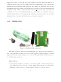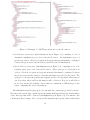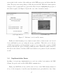
1
A Customizable Middleware Framework
for Accessing Mobile Sensors
!"! # $ %$
! & &$ ' $ ( )$ &"$ ) *+) , - !
. /0. 1 / .2.
3 ./. .+$ 4556
Randolph Carter..
Acknowledgments
I would like to thank my supervisor Ioannis Fudos, Assistant Professor at the Computer
Science Department of the University of Ioannina, for his time, support and patience, during
the elaboration of this thesis. I would also like to thank Associate Professor Evaggelia Pitoura and Dr. Apostolos Zarras for their help and valuable comments. I am grateful for the
opportunities, the experiences and the knowledge that I gained from my collaboration with
the members of the The Distributed Management of Data Laboratory. Last but not least,
I would like to thank my friends and colleagues: Xenia, Antreas, Toula, Giorgos, Nikoleta,
Kostas, Marina and Irini, for their help all these years; and the girl with the strange name.
Zissis K. Plitsis
Contents
Contents
i
List of Figures
iii
List of Tables
v
1 Introduction
1
2 Wireless Sensors and Sensor Networks: An Overview
4
2.1
Wireless Sensor Networks . . . . . . . . . . . . . . . . . . . . . . . . . . . .
2.1.1 Applications Issues in Wireless Sensor Networks . . . . . . . . . . .
2.1.2
2.1.3
4
6
Hardware Technology of Wireless Sensors Networks . . . . . . . . . .
Networking and Query-Processing in Wireless Sensors Networks . . .
8
10
2.1.4 Security and Privacy in Wireless Sensors Networks . . . . . . . . . .
2.2 Commercial Mobile Sensors . . . . . . . . . . . . . . . . . . . . . . . . . . .
2.2.1 Nokia Observation Camera . . . . . . . . . . . . . . . . . . . . . . .
12
13
16
2.2.2
2.2.3
IRIDA GSM . . . . . . . . . . . . . . . . . . . . . . . . . . . . . . .
GSM/SMS Remote Control Module BieneRemote16GM . . . . . . .
17
19
2.2.4 TCS-AWS: GSM Autonomous Weather Station . . . . . . . . . . . .
2.3 Middleware, Web Services and Messaging . . . . . . . . . . . . . . . . . . .
20
24
3 A Middleware Framework for Accessing Mobile Sensors
28
3.1
3.2
3.3
Introduction and System Architecture . . . . . . . . . . . . . . . . . . . . .
Mobile Sensor Customizer . . . . . . . . . . . . . . . . . . . . . . . . . . . .
Server and WEB Page Proxies . . . . . . . . . . . . . . . . . . . . . . . . .
28
32
36
3.4
Implementation Issues
. . . . . . . . . . . . . . . . . . . . . . . . . . . . .
37
4 Use Cases
4.1 A Framework Instance for a GSM-enabled Autonomous Weather Station . .
42
42
i
4.1.1
4.2
Interface and Implementation Details . . . . . . . . . . . . . . . . .
45
A Framework Instance for a Mobile Observation Camera . . . . . . . . . . .
4.2.1 Interface and Implementation Details . . . . . . . . . . . . . . . . .
4.2.2 Protocols . . . . . . . . . . . . . . . . . . . . . . . . . . . . . . . . .
46
47
49
5 Performance Evaluation
56
5.1 Customization Overhead . . . . . . . . . . . . . . . . . . . . . . . . . . . . .
5.2 Middleware Overhead in the Weather Station Use Case . . . . . . . . . . . .
56
59
5.3 Middleware Overhead in the Camera Use Case . . . . . . . . . . . . . . . . .
67
6 Conclusions and Future Work
73
Bibliography
76
Appendix
80
Author’s Publications
84
Short CV
86
ii
List of Figures
2.1 GSM Remote Monitoring and Alarm System, XR5 Data Logger for pressure,
temperature, level, flow, weather, power, vibration, etc with the use of GSM
Modem (Wavecom WCOD2 GSM modem). . . . . . . . . . . . . . . . . . . .
2.2 Nokia Observation Camera sending MMS or e-mail messages with image and
13
temperature data. . . . . . . . . . . . . . . . . . . . . . . . . . . . . . . . . .
2.3 Nokia Observation Camera. . . . . . . . . . . . . . . . . . . . . . . . . . . .
2.4 IRIDA GSM from Autotech . . . . . . . . . . . . . . . . . . . . . . . . . . .
15
15
17
2.5 GSM/SMS Remote Control Module BieneRemote16GM . . . . . . . . . . . .
2.6 Installed GSM Autonomous Weather Stations . . . . . . . . . . . . . . . . .
20
23
3.1 Architecture Layers . . . . . . . . . . . . . . . . . . . . . . . . . . . . . . . .
3.2 System Architecture . . . . . . . . . . . . . . . . . . . . . . . . . . . . . . .
30
32
3.3 The XML schema for MSCDs. . . . . . . . . . . . . . . . . . . . . . . . . . .
3.4 Example of a MSCD specification for a mobile camera. . . . . . . . . . . . .
33
34
3.5 Web-based Interface for the Autonomous Weather Station, part of the initiation commands. . . . . . . . . . . . . . . . . . . . . . . . . . . . . . . . . . .
3.6 Web-based Interface for the Nokia Observation Camera, some of the commands
35
of the mobile camera that be selected. . . . . . . . . . . . . . . . . . . . . .
3.7 “End-user” case for mobile camera. . . . . . . . . . . . . . . . . . . . . . .
36
37
4.1 Web-based Interface for the Autonomous Weather Station. . . . . . . . . . .
4.2 Web-based Interface for the Autonomous Weather Station, after submitting
44
one command to the sensor. . . . . . . . . . . . . . . . . . . . . . . . . . . .
4.3 Autonomous Weather Station. . . . . . . . . . . . . . . . . . . . . . . . . . .
45
46
4.4 Web-based Interface for the Nokia Observation Camera, in the “End-user”
(simple) case. . . . . . . . . . . . . . . . . . . . . . . . . . . . . . . . . . . .
4.5 Filling delivery information. . . . . . . . . . . . . . . . . . . . . . . . . . . .
48
49
4.6 Setting up delivery destination. . . . . . . . . . . . . . . . . . . . . . . . . .
49
iii
4.7 Popup window. . . . . . . . . . . . . . . . . . . . . . . . . . . . . . . . . . .
51
4.8 Results page. . . . . . . . . . . . . . . . . . . . . . . . . . . . . . . . . . . .
4.9 Using the WAP interface in the forth scenario. . . . . . . . . . . . . . . . . .
4.10 Query protocols for the two scenarios. . . . . . . . . . . . . . . . . . . . . . .
51
52
54
5.1 Customization Process of different description files . . . . . . . . . . . . . . .
5.2 Middleware Overhead Measurements, for 10 Commands description file . . .
58
65
5.3 Middleware Overhead Measurements, for 50 Commands description file . . .
5.4 Breakdown of overall response time for experiment (i) . . . . . . . . . . . . .
67
70
5.5 Breakdown of overall response time for experiment (ii) and (iii) . . . . . . .
70
1
82
Part of the GSM Autonomous Weather Station description file.
iv
. . . . . . .
List of Tables
2.1 Sensors hierarchy in wireless sensor networks, each platform class handles different types of sensing. . . . . . . . . . . . . . . . . . . . . . . . . . . . . . .
9
2.2 An example of Nokia Observation Camera instructions; note: the underline
character ( ) is used for space in the SMS message. . . . . . . . . . . . . . .
16
2.3 Some of Irida GSM instructions. . . . . . . . . . . . . . . . . . . . . . . . . .
2.4 An example of GSM/SMS Remote Control Module BieneRemote16 (standard
version) control commands. . . . . . . . . . . . . . . . . . . . . . . . . . . .
18
21
2.5 TCS-AWS: GSM Autonomous Weather Station, some of the commands in
SMS messages. . . . . . . . . . . . . . . . . . . . . . . . . . . . . . . . . . .
22
2.6 Classification of the above four sensors. . . . . . . . . . . . . . . . . . . . . .
24
5.1 Customization time for the middleware framework in four cases, according to
the size of the sensor description file in number of commands described. . . .
5.2 Parameters that effect Middleware overhead in the Weather Station use case
57
and description of the following sets of experiments. . . . . . . . . . . . . .
5.3 Middleware overhead measurements in the case of one command in one SMS
message, in the Weather Station use case . . . . . . . . . . . . . . . . . . . .
60
61
5.4 Middleware overhead measurements in different case of requests, in the Weather
Station use case (for the first type of our implementation). . . . . . . . . . .
62
5.5 Middleware overhead measurements in different case of requests, in the Weather
Station use case (for the second type of our implementation). . . . . . . . . .
63
5.6 Middleware overhead measurements in different case of requests, in the Weather
Station use case, for our implementations with different sizes of description files
(10 commands and 50 commands). . . . . . . . . . . . . . . . . . . . . . . .
5.7 Response time and middleware overhead for experiment (i). . . . . . . . . .
5.8 Response time and middleware overhead for experiment (ii). . . . . . . . . .
64
68
69
5.9 Response time and middleware overhead for experiment (iii). . . . . . . . . .
69
v
Abstract
Plitsis, Zissis, ZP. MSc Computer Science Department, University of Ioannina, Greece. October, 2006. A Customizable Middleware Framework for Accessing Mobile Sensors. Thesis
Supervisor: Ioannis Fudos.
Sensing, monitoring and controlling devices have been used in industry for many years.
The evolution of microcomputers and the increasing needs for sensing and controlling have
led to new sensing devices being smaller, cheaper, capable of new applications and connected in wireless networks. This new area of research and development is known as sensor
networks or Wireless Sensor Networks (WSN). WSN consist of hundreds of self-contained,
battery-powered sensing devices that measure and communicate wirelessly environmental
data. They are embedded in the environment, can act proactively, and can be presented as a
new “tier in the Information Technology ecosystem”. A global computing environment built
on top of the Word-Wide Web can integrate sensors and provide the appropriate applications
and interfaces to utilize different kinds of sensors. To handle such distributed, heterogeneous
and oblique systems we shall adopt the approach of a “Middleware Framework”, as the software layer between the operating system and the applications on each side of the system.
Our goal is to integrate a specific kind of sensor devices in a global computing environment. These are GSM-enabled sensor devices, that can communicate and be instructed
through the GSM network, the network of cell phones. Specifically, we focus on sensors
controlled by SMS messages that exchange information through SMS or MMS messages.
We provide the means to integrate different mobile sensors in our computing environment
by using the proprietary communication protocols (usually SMS messages) and the specific
characteristics of the mobile sensor. Starting from GSM enabled devices we automate the
process of integrating these devices in a global computing environment with the use of XMLbased sensor descriptions. To this end we proposed a customizable middleware framework
was proposed.
vi
MSc ! "##$ A Customizable Middleware Framework for Accessing Mobile
Sensors. %!&' ( )*
+ ,&, -
,& ( &
&. /
& & * */
0 & . & (, 1 0
( 0
2Wireless Sensor Networks, WSN). / ( * 3 (/ 3
/* * & * //& !( % & !( * / !( .4 & / 5
*
6 . 2a new
“tier of IT ecosystem”). 7% 3
3 !( 2global computing environment) * ( 3 3
/
&. ( & /& .
.
* & & ( .43
/ /(
* * (
3 *
& ( (
3 & /3 * 3 & 3
3 !( 03
* / 3 GSM. 3
&. 3 ( * 2SMS *8 & &
( ( &
2SMS MMS *8 &. &
(
/ GSM *
3 /( 39
.
( ( * //
/ . & XML 3
/ %/(9
:
* GSM 3 $ ( ;& 3 * " ( (4 & . / ( ( 3 & /&' .( & /*
. !
4 9
/ * //
/*
,
, //& (query-processing) /
( ( & ( & ( /* !( ( /(
3 (middleware) GSM " ( .4 & GSM 9
. /(
3 //* (Web Services)
( .
* .
/( <
( (4 /(
3 GSM * 9
. 3 (customization) ( /( ,& & & . = ( /* 3 (
" ( .
9
* /
*
/(4 *
( 3 3 > 3 ( &. . &
GSM 3 3 &. ? ( (
3 3 ,* &. /( (
& *
& * & (
( $ (
Chapter 1
Introduction
This work addresses the issue of accessing transparently mobile sensors through a customizable middleware framework.
Sensing, monitoring and controlling devices and techniques have been used in industry
for many years. The evolution of microcomputers along with Moore’s law and the increasing needs for sensing and controlling in our complex environment have led to new sensing
devices being smaller, cheaper and capable of applications that it was impossible to realize
ten years ago. This new area of research and development is known as sensor networks or
Wireless Sensor Networks (WSN), because is more useful and frequent to communicate with
hundreds of those sensing devices wirelessly. Wireless sensor networks consist of hundreds
of self-contained, battery-powered computers that measure and communicate wirelessly environmental data, They are embedded in the environment, can act proactively, and can be
presented as a new “tier in the Information Technology ecosystem”. Those abilities improve the “proactive computing” and “pervasive computing” (or “ubiquitous computing”)
paradigms. In proactive computing computers anticipate human needs and act on human’s
behalf. Pervasive computing refers to the next generation computing environments with information and communication technology everywhere, for everyone, at all times.
A global computing environment built on top of the Word-Wide Web can integrate sensing
devices. A global computing environment should provide the appropriate applications and
interfaces to utilize different kinds of sensors. This is the concept of embedded Internet,
embedded deeper in any real environment using wireless sensor networks. Developing such
1
distributed, extreme heterogeneous and embedded systems is a challenge. To handle such
distributed, heterogeneous and oblique systems we shall adopt the approach of a “Middleware
Framework”. The ObjectWeb consortium gives the following definition of middleware:
“In a distributed computing system, middleware is defined as the software layer that lies
between the operating system and the applications on each side of the system.”
(middleware.objectweb.org, [1])
Thus, the term middleware is used to describe web servers, application servers, content management systems, proxies, wrappers and similar tools supporting the application development
and delivery process. The middleware is central to modern information systems based on
XML, SOAP, Web services, and service-oriented architectures.
Our goal is to integrate a specific kind of sensor devices in a global computing environment. These are GSM-enabled sensors, that can communicate and be instructed through the
GSM network, the network that any cell phone uses. The term “mobile phone” is identical to
the term “cell-phone”, so the term “GSM-enabled sensor” is used alternatively with the term
“mobile sensor”, meaning the sensing device that wirelessly transfer data through the GSM
network. Specifically, we focus on GSM-enabled sensor devices, controlled by SMS messages
that exchange information through SMS or MMS messages. Besides using the proprietary
communication protocols (usually SMS messages) and the specific characteristics of the mobile sensor, we provide the means to integrate different mobile sensors in our computing
environment.
The work presented in this thesis proposes a middleware framework that enables uniform
access to mobile sensors. We introduce a mobile sensor description that is used to configure
the middleware according to the sensor specifications and to provide the interface for accessing the mobile sensor.
The remaining of this thesis is structured as follows. Chapter 2 provides a brief overview
of Wireless Sensor Networks, a survey of mobile sensors for industrial and commercial use
and discusses similarity to our work, from the middleware prespective. Chapter 3 describes
our middleware framework, discusses the process of customization based on a proposed sensor description standard, the system architecture and finally presents implementation issues.
Chapter 4 details the use cases of mobile sensors, Chapter 5 presents performance evaluation
results and finally, Chapter 6 offers conclusions.
2
Chapter 2
Wireless Sensors and Sensor
Networks: An Overview
2.1 Wireless Sensor Networks
2.1.1
Applications Issues in Wireless Sensor Networks
2.1.2
Hardware Technology of Wireless Sensor Networks
2.1.3
Networking and Query-Processing in Wireless Sensor Networks
2.1.4
Security and Privacy in Wireless Sensor Networks
2.2 Commercial Mobile Sensors
2.2.1
Nokia Observation Camera
2.2.2
IRIDA GSM
2.2.3
BieneRemote16GM
2.2.4
TCS-AWS: GSM autonomous weather station
2.3 Middleware, Web Services and Messaging
2.1
Wireless Sensor Networks
Technology that is commercially available today gives rise to engineering efforts that have
produced complete devices with processing, storage, sensing and communication functions,
4
devices that are smaller and cost less. The last 50 years, a new class of computers has
appeared about once a decade, modern computing is progressing through mainframes, microcomputers, personal computers and mobile computers. Each successive model relies upon
technical advantages, to make computing available in a way not previously possible. Each
has introduced new uses for computer technology and each succeeding generation is smaller,
more plentiful and more intimately associated with personal activity than the generation that
proceeded it. Wireless Sensor Networks (WSN) appear as a new class, they follow the same
trends of size, number, and cost; but rather than being devoted to personal productivity
tasks, they make it possible to perceive what takes place in the physical world in ways not
previously possible. One can consider Wireless Sensor Networks as:
“Thousands of tiny low-power devices spread over large physical spaces collaboratively
monitoring the environment, guide vehicles and predict potential faults in buildings,
bridges, roads and rails.”
Communications of ACM, June 2004/vol. 47, no. 6 [2]
Wireless Sensor Networks are new important tier in the IT ecosystem and a emerging
domain of active research and development involving issues in hardware and system design,
networking, distributed algorithms, programming models, data management, security and
social factors. Through the use of Wireless Sensor Networks the vision of an Embedded Internet becomes reality; in this vision networks of interconnected computing devices deeply
embedded into the physical environment transform whole fields of science, engineering and
manufacturing by providing detailed instrumentation of many points over large spaces, both
natural and artificial. As an example: the Global System for Mobile Communications (GSM),
the most popular standard for mobile phones in the world, can be used in connecting observation cameras, weather stations and other kinds of sensors to transmit images, temperature
information and other data. By doing so we implemented an embedded wireless sensor network over the common network of cellural phones.
The pervasive instrumentation that wireless sensors networks provide will be of great value
in many applications, including understanding ecosystems dynamics, setting land-use policy,
protecting property, efficiently operating and managing machinery and vehicles, establishing perimeter and building security, protecting packages and containers, monitoring supply
chain management and helping deliver health care. Sensors networks can extend to monitoring interactions among many objects within these domains, ensuring asset management,
ubiquitous computing environments and emergency response. Moreover, those networks help
5
feed information to autonomous distributed control devices. They may help in applications
used for road safety, fire prevention, temperature control, precision agriculture systems and
much more. By using a middleware framework to improve the communication and proactive
capabilities those networks can have.
Realizing important aspects of the embedded Internet vision includes the design and development of applications, hardware needed to collect physical data, algorithms for gathering
and analyzing this information and methods for robust and secure operation. These issues
are discussed in the remainder of this section.
2.1.1
Applications Issues in Wireless Sensor Networks
The first aspect of the embedded Internet vision, as described before, has to do with the
applications of Wireless Sensor Networks that have been designed and developed. There
are several real-world deployments of environmental monitoring such as habitat monitoring
with sensors networks which deliver to ecologists data on localized environmental conditions,
about animals, plants and people. This is an example of the applications that make use of
sensors networks. Nowadays the scale of the nodes in these sensor networks can be compared
to the scale of the organisms under study, and these networks are ranging in size from tens
to thousands of different sensors (nodes) within a habitat patch.
Several real-word deployments of “habitat monitoring applications” in the US and all over
the world have leaded the development of a network architecture, that is flexible enough and
multilevel. They make use of different kind of sensors grouped in patches networks involving
nodes with heterogeneous sensing capabilities, processing power and storage.
Habitat monitoring applications require ways to specify and deliver data of interest, so
they need routing and tasking service. The data of interest can be either streaming or triggers
and the task service has to cope with a dynamic topology of poor-quality links, potentially
arbitrary termini (sinks) of data form nodes with minimal resources. The low-power mode of
the system is needed for the long-term operation and the current solution is duty cycling, or
changing the amount of time the subsystem is active during any given period, at several levels.
The percentage of time each node is awake is known as the node’s duty cycle, and a variety
of approaches are available for achieving low-duty-cycle operation. Finally networks health
monitoring and management are necessary for networks users to both trust the incoming
6
measurements and ensure the network’s performance and longevity. The health-monitoring
system relies on explicit and implicit signals. Explicit signal can be the battery voltage of a
sensor which provides information about the remaining capacity and implicit signal can be,
for instance, out of range readings in the humidity that indicate a fault.
There are also many examples of environmental monitoring systems such as systems
developed by Harvey Mudd College Harvey Mudd College Center for Environmental Studies with embedded networks that study issues in the relationship between human life and
both natural and human-built environments [3] and [4] with distributing remote sensors that
would provide habitat monitoring via a wireless network grid to understand how local conditions as temperature, light intensity, and noise affects lizard habitats. Other examples are
NASA’s Volcano ‘sensorweb’ project [5] and other autonomous observing sensorwebs ([6] and
[7]) and UC Berkeley’s habitat modeling at Great Duck Island, Maine ([8] and [9]). On a
much larger scale there are Environmental Observations and Forecasting Systems, such as the
EOFS project studying Oregon’s Columbia River estuary (CORIE system) [10] and FloodNet
intelligent sensor network, which is included in EOFS of the University of Southampton’s
Envisense Center [11], a Center for Pervasive Computing in the Environment, and is designed to provide more accurate flood warnings. Future projects include NASA’s sensorwebs
in New Mexico deserts and in Antarctica, and sensors networks on both Mars and Jupiter’s
moon, Europa as mentioned in [12] about sensrowebs. In addition researchers working on diverse projects have developed novel applications for sensor networks technology and projects.
Projects like GlacsWeb, about sub-glacial bed deformation [12]; sensor networks for detecting
vehicles transporting radioactive isotopes [13] and detecting location of a sniper in a complex
urban terrain [14]; and “The Flock” in the core of the computer engineering curriculum in
which “mote sensors sing” [15], are examples of this diversity of applications. Our work provides a complementary middleware solution for integrating different GSM-enabled sensors in
a computing environment with heterogeneous components and distribution.
The long-term outdoor deployment of such environmental monitoring systems with Wireless Sensors Networks stress reliability, low-power operation, network protocols, data quality
and new experimental processes. The future habitat monitoring networks and wireless sensor networks applications in general would be enhanced with robust localization, calibration,
clock synchronization and data processing.
7
2.1.2
Hardware Technology of Wireless Sensors Networks
The second aspect is the hardware technology. The underlying hardware technology for wireless sensors networks, consisting of perhaps thousands of integrated devices, with built-in
processing, storage and sensor with RF transceiver, energy storage and antenna, is evolving quickly and a signature style of design is formulated. Wireless sensor networks combine
processing, sensing and communications into tiny embedded devices. Peer-to-peer communication protocols then combine the individual devices into an interconnected mesh network
where data is seamlessly routed among all the nodes. These networks require no external
infrastructure and can scale to hundreds or even thousands of nodes. Critical to the operation of any sensor network device is the ability to satisfy harsh always-on power requirements
and the periodic recharging is not possible for most cases. Special purpose sensor nodes are
purposely designed to satisfy flexibility in order to be as small and inexpensive as possible. High-bandwidth sensors contain the built-in processing and communication capabilities
needed to deal with complex sensor streams, including video and voice processing. Traditional
network abstractions are generally not suitable for wireless sensors networks, for instance,
unlike traditional operating systems, operating systems for wireless sensors networks must
tightly integrate wireless connectivity, while gate-way-class and high-bandwidth nodes use
more traditional operating systems.
There are four main platform classes that have emerged recently in wireless sensor networks, as Table 2.1 shows, which is mentioned in [2]. Initial deployment experience has
show that sensor network systems require a hierarchy of nodes starting at low-level sensors
and continuing up through high level data aggregation, analysis and storage nodes. This
tiered architecture is common in virtually all sensors networks, it starts with the head, or
gateway nodes, which provide an interface into many existing types of networks and then
includes: acoustic, video or chemical sensors as examples of high-bandwidth nodes requiring
more computational resources and communication, sensors placed on windows and doors for
instruction detection as examples of generic sensing devices and finally “mini-motes” like
low-cost security tags, attached and tiny for tracking mobile assets, as well as personnel.
Moreover, the data produced by the sensor network gain scientific validity through a verification process and collaboration, in other words there is the need for frequent calibration and
the data have to be compared to independent calibrated instruments. A verification network
is the application component responsible for collecting these independent readings and has
often fewer but more-established sensing devices, of the upper rows of Table 2.1. It needs
to provide the data quickly so the function of a sensor patch can be adjusted, faulty sensors
8
Table 2.1: Sensors hierarchy in wireless sensor networks, each platform class handles different
types of sensing.
Class / Level
# of Nodes
Examples
First
A few gateway nodes
Web interfaces, databases
Second
Dozens of highbandwidth sensors
Cameras, microphones
Third
Hundreds of generic
sensor nodes
Door, window,
motion sensors
Forth
Thousands of specialpurpose sensors
Asset tags
can be eliminated and help the maintenance of the network. In our middleware framework
the sensors that we use are of the class of high bandwidth sensors and gateway nodes.
Once again, the operating system running on a particular platform must be matched to
the platform’s underlying hardware capabilities. For special-purposes and generic-sensor-class
devices, a special operating system called TinyOS (developed at the University of California,
Berkeley [16]) is designed to run on platforms with limited CPU power and memory space.
Unlike many embedded operating systems, it provides tight integration between wireless connectivity and networking functions. However, as platform capabilities improve, for example
in the case of the Stargate platform (a type of gateway node), more advanced operating system support is required to meet the demands of more complex applications. Multiprocessing,
preemptive tasks switching and even virtual memory support become desirable when managing multiple system functions. The Stargate node runs an embedded version of Linux
operating system and in addition to provide a range of system capabilities, Linux provides a
suite of device drivers for enabling gateway nodes to bridge to legacy networks.
Despite significant differences in device capabilities, the overall architecture for the classes
of sensor-networks platforms is remarkably similar. This similarity follows from the requirement that they seamlessly follow from the integrate wireless networking. Network support
9
must be transparent and self-configuring to allow sensor networks to scale in size and complexity. The engineering decisions about the amount of on-board memory, the amount of
CPU processing power, the type and bandwidth of wireless link determine the cost and
power consumption which influence the final design of any given sensor node. Additionally,
Moore’s law and the development of advanced wireless sensor-networking platforms influence
the age of ubiquitous sensing and actuation, and as capabilities are improving these systems
will be able to automatically act on sensor data to manage our environment, for years at a
time in potentially hostile environment without hope of human intervention.
Our work is orthogonal to communication and power considerations. The mobile sensors,
in our work, are at an upper level to the typical micronodes, as those of the third and forth
level of Table 2.1, according to their capabilities and they have additional computing power
and storage capacity. They have specific functions and usually custom made operating systems, with the use of control SMS messages or with a serial port connection. There is no
need for configuring duty cycle, as there have no power issues. Those are things that will be
detailed later, when some mobile sensors will be presented.
2.1.3
Networking and Query-Processing in Wireless Sensors Networks
Moreover, networking and query-processing issues become deeply intertwined, as queries are
continuously processed within the network, and this is the third aspect of the embedded Internet vision. Network and query processing must be co-designed to allow data self-organization
for flexible but efficient in-network storage, access and processing. In fact sensors networks
have the potential to support applications ranging from habitat and structural monitoring, to
home and building automation, to supply chain management. Users are typically interested
in continuous streams of information representing the evolving status of systems, combined
with periodic statistical reports about specific phenomena and even, when some thresholds
are used or alarm systems are triggered, those alarm messages and the data reports. Query
processing systems, provide high-level interfaces that allow users to collect and process such
continuous streams.
Speaking of stream data management, the Aurora system [17] is an experimental data
stream management system with a fully functional prototype including both a graphical development environment and a runtime system. In the future plants of the Aurora system
10
there is a distributed stream processing system, called Borealis. Apart from dynamic revision of query results and dynamic query modification, the ability of Distributed Optimization
makes Borealis useful in application of wireless sensor technology [18]. Moreover, Stanford
Data Stream Management [19] (and [20]) is another system with a first version of prototype
even available for public use.
Researchers are beginning to formulate languages and enumerate the type of queries
needed by users of sensor networks. Distributed query processing is also needed as the data
is stored and retrieved from nodes within the network. Several in-network query systems
have been built for sensors networks. Diffusion is the pioneering work, developed by the
Information Sciences Institute at the University of Southern California and presented in [21]
as the directed diffusion paradigm for Wireless Sensor Networking and in [22] as the TinyDiffusion API implementation in TinyOS [16]. There is no specific query language in Diffusion;
instead it allows application writers to choose a domain-specific query language, and focuses
on query rooting mechanisms and flexible in-network processing. A family of routing algorithms is provided and queries in the network are described by interest messages. There
is also TinyDB [23] which uses declarative queries that reflect their data processing needs,
specifying the types of data, as well as the subset of nodes of interest, along with simple
transformation over the data. Queries are written in a SQL-like language, they are the input
on a PC that sends the query into the sensor network and a number of optimizations are
might applied by the query processor. Common ground between TinyDB and Diffusion is a
query language interface for network processing and in some cases tend to give users more
control over the types of network topology and patterns of communication.
In our work, there two different networks involved the GSM network of the mobile sensors, including GPRS for communication based on packet switching, and the Internet, with
the web interfaces and the servers of our customizable middleware. This middleware framework is responsible for the execution of any information request and the utilization of those
different networks.
However, future systems will be more sophisticated than any of today’s prototypes, and
will involve many novel network requirements. The basic dimensions of design in terms
of networking mechanisms are: scope, concerning the nodes involved in a query; volume,
i.e. communication cost per unit time; complexity, concerning multiple concurrent queries;
timeliness, having to do with delays between events and quality of the query response. The
11
fact is that network aware for query processing is in its infancy, multiple complex queries
must be supported beyond the basic tree-based data collection, more sophisticated topologyconstruction algorithms and facilities are needed for storage and correlation than the available
in nowadays.
2.1.4
Security and Privacy in Wireless Sensors Networks
Finally, effective security and meaningful privacy is an other important aspect of the sensors
networks, the technical aspects of these issues must be addressed from the start of any system’s design process in the context and the applications. Sensors networks are susceptible to
a variety of attacks, including node capture, physical tampering and denial of service, while
prompting a range of fundamental research challenges.
Sensor network security should be properly addressed from the start because there are
unique new challenges in the network of limited in energy, computational and communicational capabilities sensor devices. They are also deployed in accessible areas, presenting the
added risk of physical attack and interact closely with their physical environment and with
people, posing new security problems. It is crucial that security pervade every aspect of
system design and be integrated into the system and every component of it. In this case of
wireless sensor networks, for instance, the cryptographic key establishment of the network
is very different than the well-studied same problem in previous networks that proposed a
variety of protocols and solutions. We need a secure and efficient key-distribution mechanism allowing simple key establishment for large-scale sensor networks. Better random-key
predistribution schemes and investigation of hardware support for public-key cryptography
are useful. Protection against eavesdropping, injections and modification of packets are also
important and recent research shows that software-only cryptography is indeed practical
with today’s sensor technology. Further research is needed is matters as privacy, robustness
to communication denial of service attacks and resilience to node capture. And finally important network secure services such as secure group management, intrusion detection and
secure data aggregation need improvement.
In our work again, we combine web-based interfaces and protocols with GSM-GPRS.
When it cames to security and privacy the middleware can give the solutions, as those issues
have been studied in the context of the World-wide web (e.g. the https with additional encryption/authentication layer between HTTP and TCP). In our work we don’t treat security
12
issues, but there are implementations and ideas integrated into the mobile sensors and their
functions that can be activated. The mobile sensors can distinguish among administrators
and common users and assign privileges according to the access group they belong. Some
examples will be detailed later on when some mobile sensors instances are presented.
2.2
Commercial Mobile Sensors
There are many examples of commercial mobile sensors or GSM-enabled sensors which are
available and widely used today. These sensors are part of monitoring and alarm systems and
they are useful in environmental measuring and logging. It is also common for the mobile
sensors to have the communicational capacities in order to transmit data to different kind of
networks and even to send alarm signals to the appropriate users.
Figure 2.1: GSM Remote Monitoring and Alarm System, XR5 Data Logger for pressure, temperature, level, flow, weather, power, vibration, etc with the use of GSM Modem (Wavecom
WCOD2 GSM modem).
In Figure 2.1 different parts of a remote monitoring system are shown. There are some
sensors measuring environmental parameters like pressure, temperature, level, flow, weather,
power, vibration etc, from the power system shown on the left. Those measurements are
collected by a data logger and through a GSM modem are communicated to the administra13
tor. These systems should be programmed remotely using any Windows terminal emulator
and send data to mobile phone using SMS text messages. This is a typical example of the
implementation of a monitoring system combining sensors, loggers, modems and terminals
using their functionality and properties.
The power, storage, bandwidth, communication or other capacities of the devices used
can lead to a variety of monitoring systems implementation. There are devices which include some or even all the capacities needed for this kind of systems in order to be used
stand-alone and devices specifically designed for only one function needed in the system.
There are, for example, mobile sensors that have also communication capacities, like mobile
GSM thermometer and camera sensors, and data loggers with communication capacities that
can store and send the data from connected sensors through GSM or computer networks.
Of course the example of specifically designed devices-parts of the monitoring system is the
above figure (Figure 2.1).
There is a vast variety of mobile sensors used in any kind of monitoring systems form
industrial use to commercial use and of course in house monitoring. In addition to measuring and monitoring environmental parameters they should also communicate the data
collected and sometimes set alarms. The sensors are designed in order to be connected and
communicate their data and status, informing about their measurements and their normal
or not normal functionality. There are sensors which need other communication devices,
like any kind of modems or data loggers; and other sensors which include communication
capacities and can be connected to many networks. For this kind of design, which integrate a
monitoring and a communication system, typical examples are some mobile cameras: GTM
module network and dedicated PC based software management from AxelProd [24], GSM
alarm monitoring system and GPS vehicle locating system like the Patriot unit from Spy
Equipment, Law Enforcement Systems [25], the TCS-CAM developed by DPS-Promatic, a
reliable GSM digital camera for stand alone applications, which is used to take a pictures
and send it over a GSM network [26], and Nokia Observation Camera (Figure 2.2) used to
take pictures and more [27].
In addition, Data loggers have digital and analog inputs for the connection of devices with
analog outputs (temperature sensors, pressure sensors etc) or digital outputs and signals from
alarms. There are also data loggers with independents outputs of activation and deactivation
of devices that are connected; and their communication capabilities might include commu-
14
nication ports (RS-485 or RS-232 ports are common) or/and GSM - GPRS connection with
included modems. These loggers have of course different methods of control, in a remote
manner, used for activation and deactivation of the individual devices that are connected to
them. These are some examples of the latter data loggers: AUTOTECH Irida/GSM, which
offer remote control through GSM network [28], Ekopower Complete Data-Logger System
EKO21[29] and GuardMagic SCT, GuardMagic SC2x2, GuardMagic SC4x4 devices [30].
Figure 2.2: Nokia Observation Camera sending MMS or e-mail messages with image and
temperature data.
Continuing, some examples of mobile sensors, their specifications and capabilities will
be presented, sensors that will be use in our middleware framework. Hence, details about
Nokia Observation Camera, IRIDA, BieneRemote16 and Weather Station will conclude this
introduction to commercial mobile sensors.
Figure 2.3: Nokia Observation Camera.
15
2.2.1
Nokia Observation Camera
Nokia Observation Camera is shown in Figure 2.2 and Figure 2.3. This camera is a remote
imaging stand alone device with a motion detector, thermometer and microphone. Images
can be captured and sent to any multimedia messaging (MMS) enable mobile phone with
color display, or to an e-mail address. Temperature can be sent, after user request, or if the
temperature goes out of a set range; the camera can be also programmable to take images
automatically at a designated time interval, or when the motion detector is triggered. Finally,
the microphone can be used to listen to the environment that the camera is installed into.
The site for the Observation Camera Support is [27] and the user manual can be found there.
Table 2.2: An example of Nokia Observation Camera instructions; note: the underline character ( ) is used for space in the SMS message.
Task
Set a name for the camera
Capture an image and send it to your
mobile phone
Capture an image and send it to another
phone number or e-mail address
Set the image resolution to high (1),
normal (2), or compact (3)
Set motion detector off
Request the current temperature
Set temperature alarm off
Set the sending of current
temperature with images on or off
Set the user name for the connection
Set connection security on or off
Define the master user.
The e-mail address is mandatory
Add a new use, and give the right to
capture images and/or
use the audio connection
Remove a use.
The user can be removed
based on either the user name
or the phone number
Set the PIN code request on or off
SMS Command
25 camera name
1 or image
1 phone number/e-mail address or
image phone number/e-mail address
11 number
2 off or detection off
3 or temp
15 off
13 on/off
41 user name
45 on/off
8 security code user name phone
number e-mail address or
master security code user
name phone number e-mail address
5 security code user name user’s
phone number on on or
add security code user name user’s
phone number on on
6 security code user name/
phone number or
remove security code user name/
phone number
22 PIN code on/off
Someone can control and configure the camera with short messages (SMS), and the PC
Suite for Nokia Observation Camera software is provided for more advanced functions. This
camera is approved for use on the GSM 900/1800 network and besides GSM network coverage, a GPRS enabled mobile subscription with a SIM card and MMS service will be needed
for its function. As mentioned above an MMS and SMS enable mobile phone with color
16
display can be used to control the device and deliver the data. In our work we make use of
a GSM modem for control and an e-mail address for receiving images. Some of the specific
instructions and requests with SMS messages to the camera are gathered in Table 2.2 and
through that table more camera specifications can be discussed. Please note that in the SMS
Command column of Table 2.2 the underline character ( ) is used for spaces and that those
commands can be sent in one SMS separated by a comma. There are commands about getting information (image or/and temperature), setting the camera parameters, the automatic
imaging and the connection, and finally, user and security commands.
2.2.2
IRIDA GSM
Figure 2.4: IRIDA GSM from Autotech
Irida GSM logger from Autotech is shown in Figure 2.4. This logger allows wireless remote control through cell phone and can be useful in remote paging, telemetry and alarm
applications. It has been programmed on a “user friendly” philosophy, by SMS messages or
by a PC through a serial port.
IRIDA GSM has :
• 4 independent outputs for activation or deactivation (with or without time delay) of
devices that have been connected to these outputs either at home or in the factory.
Examples of such devices are: various household electric or electronic devices.
17
• 4 digital inputs for the connection of devices with N.O. - N.C. outputs or signals coming
from alarms or directly from gas, motion, fire detectors etc.
Table 2.3: Some of Irida GSM instructions.
Task Description
Programming Commands
Enter access code
Store the Supervisor phone
number in memory
Replace the current code (default: 1111)
with a new one
Store the phone number from which the
system will receive commands and the
sequence of commands to be executed
Store a keyword and the sequence
of tasks to be executed
SMS Command
Syntax/Examples
PASS
SUPERVISOR
PASS=1111#
SUPERVISION=6970333330#
PASS=1111# (the 1st time)
CHPASS=1111.1234 #
Store programming values for
alarms 1 to 4
SETMALARMx
Store in one of the memory locations
the predefined SMS that the user
will receive in case of alarm
Set and store the time and date
in the GSM module
Indicates if a notification SMS
will be sent to the user’s phone
Indicates if a user-defined SMS message
will be sent to the phone number that
has been programmed in memory
Output Functions
Output activation and deactivation
Output activation for the time
indicated by parameter xxx
(000 to 999 minutes or seconds)
Then the output is deactivated
Output deactivation for the time
indicated by parameter xxx (min. or
sec.) Then the output is activated
Remote Control Commands
Direct outputs management
SETSMSx
Request for a notification SMS
to supervisor phone number
CHPASS
SETCALLx
SETMACROx
SETDATE
SETCALL1=6970333330 OUT=ONMIN052 OUT2=OFF OUT3=XOR OUT4
=OFF-SEC035 CALLBACK1 REPORT#
SETMACRO1=*IRIDA* OUT1=ONMIN052 OUT2=OFF OUT3=XOR OUT4
=OFF-SEC035 CALLBACK1 REPORT#
SETALARM1=6977763000 IN1=ON
IN2=OFF AN1>80 AN2>55 AN2<35
AN3<10 OUT1=0N-MIN052 OUT2=OFF
CALLBACK1 REPORT #
SETSMS1=<A BURGLARY IS
CURRENTLY IN PROGRESS AT THE
SHOP IN 34 AEOLOY ST.> #
SETDATE#
REPORT
SMS
ON and OFF
ON-MINxxx and
ON-SECxxx
SETCALL1=6970333330 OUT1=ONMIN052 OUT2=OFF OUT3=XOR
OUT4=OFF-SEC060 REPORT #
or
SETALARM1=6557763000 IN1=ON
AN1>80 AN3<10 OUT1=ON-MIN052
SMS CALLBACK1 REPORT #
OFF-MINxxx and
OFF-SECxxx
COMMAND or COM
STATUS
COMMAND OUT1=ON
OUT3=XOR OUT4=ON-SEC035 #
STATUS #
• 4 analog inputs for the connection of temperature sensors, pressure sensors, humidity sensors etc., or any other system that provides readings through analog outputs
(Alternatively, the analog inputs may be used as additional digital inputs).
• 4 independent timers for each Relay output with time function. (1sec - 999min)
18
• RS-485 & RS-232 ports communication.
• And additionally the capability to expand the outputs and inputs by multiplying their
number is provided.
The activation or deactivation of all individual devices that are connected can be remotely
controlled by:
1 commands through SMS that the device receives from a predefined telephone number
(supervisor) or from any telephone number with a password.
2 non-answered, toll-free calls to the device (utilizing the calling number identification
service)
3 keywords sent by the user in an SMS (the user can program up to 8 different keywords).
There are also 8 different programmable combinations of alarm signals, the device can
provide information in regular time intervals about the inputs-outputs status or information
regarding the overall status of the device by an SMS or even by a non-answered call.
More information can be found at the site for the Irida GSM [28] and the user manual
can be downloaded there. This logger is approved for use on the GSM 900/1800 network and
besides GSM network coverage, communicate/transfer data with the use of GPRS service.
Some of the specific instructions and requests with SMS messages to Irida are gathered in
Table 2.3. Those commands must always be terminated with the sharp character (#), and
there are commands about programming, remote control, and output functions.
2.2.3
GSM/SMS Remote Control Module BieneRemote16GM
BieneRemote16GM logger, from Biene Electronics, is shown in Figure 2.5, it’s a GSM/SMS
remote control module that can be applicable in cases of remote monitoring in different kind
of stations, as transformer and wastewater; remote control and alarm systems. There are
four different versions of this module: BieneRemote16GM-S for digital signal monitoring and
alarming, BieneRemote16GM-2A, BieneRemote16GM-4A both for analog and digital signal
monitoring, and BieneRemote16GM-2SMT for temperature monitoring. The user can receive an SMS message at occurrence of a certain event, send a SMS message for managing of
various equipment, or requesting information about the target system status. Independent
monitoring up to 14 inputs and local control up to 6 outputs is possible. The site for the
19
Figure 2.5: GSM/SMS Remote Control Module BieneRemote16GM
GSM/SMS Remote Control Module BieneRemote16GM is [31] and the user manual, demos
and other information can be found there.
Someone can control, be informed and configure this remote control module with short
messages (SMS). It has a built-in two-band (900/1800) or tri-band (900/1800/1900) Telit
GM862 GSM Modem, programmable via SMS embedded software and on board power supply
voltage regulator in a small size package. Some of the specific controls commands for the
standard version (BieneRemote16GM-S) are shown in Table 2.4. The user can get the current
status, set or reset the outputs and the notification, set the logger ON-LINE, and enable or
disable switch active /passive answer SMS.
2.2.4
TCS-AWS: GSM Autonomous Weather Station
In the case of the TCS-AWS weather stations, from Telecom Control Systems, we have a
reliable GSM based autonomous Weather stations, and there are available various versions
to measure parameters like wind speed and direction, temperature, relative humidity, precipitation. Figure 2.6 illustrates installed weather stations. Real time data can be requested
with an SMS or listened through a voice synthesizer, placing a call to the unit; data can be
logged on a 4 Mbit logger or can be sent directly to a server via GPRS UDP packets.
20
Table 2.4: An example of GSM/SMS Remote Control Module BieneRemote16 (standard
version) control commands.
Task
SMS Command
Get Status
jjjj0
Set Output 1
Set Output 2
Set Output 7
Event notification enable
jjjj1
jjjj2
...
jjjj7
jjjj8
Set ON-LINE
jjjj9
Reset Output 1
Reset Output 2
Reset Output 7
Event notification disable
Nnnn1
Nnnn2
...
Nnnn7
Nnnn8
Enable/Disable answer SMS
Nnnn9
Description
Get input state, output state, charge status and
reference source (for ADC)
for instance: I=111111111111 O=10000000 CH=100%
Set Output 1 to ‘1’ (to ‘0’ on terminal block)
Set Output 2 to ‘1’ (to ‘0’ on terminal block)
...
Set Output 7 to ‘1’
Set active mode Event notification enable
Set ON-LINE (BieneRemote dial to first in
phone book number)
Set Output 1 to ‘0’ (to ‘1’ on terminal block)
Set Output 1 to ‘0’ (to ‘1’ on terminal block)
...
Set Output 1 to ‘0’
Set passive mode Event notification disable
Enable /disable switch active /passive answer
SMS (for alarm mode only). Default - disable
TCS-AWS (Telecom Control Systems for Autonomous Weather Station) control electronics has the following features:
• Built in Dual Band modem model Siemens TC35
• Wide power supply range: 12VDC to 35VDC or 12VAC to 24VAC and a lead battery
constant voltage charger on board
• Solar panel power management on board
• Speech synthesizer to speak weather data upon call
• SMS handling to receive commands and send Weather status and alarms
• Alarms: wind speed and temperature with programmable thresholds. Rainfall alarm
available on versions with rain collector.
• Automatic message every 30 or 60 minutes in CSV format
• Optional
– DTMF decoder to allow access only upon touch tone password
21
Table 2.5: TCS-AWS: GSM Autonomous Weather Station, some of the commands in SMS
messages.
Task
Enable or disable the generation of an ALeRt SMS
Store and read text for programmable Alarm MeSsages
Auto Reset gsm Modem daily at 3:00 am
Change Admin Password
CalL Back the tel data number indicated
Check gsm rf Signal Quality (0-32)
Change User Password
DeBuG: send a copy of all incoming messages
to TELephone Nr.8
Get LoG: read a LOG string by SMS with
comma separated variables
Request an SMS with weather data
INItialize: Initialize all parameters to the INIT
default value
Set LoGtoGPRS parameters
Define period for weather data sampling and averaging
NO Acknowledgment: inhibit SMS acknowledgment
Set PIN for the SIM card
Set PPP parameters for GPRS connection
Give PassWorD to enable any following command by SMS
Read/Write PoWeR variables
Software RESet the board
Read/write Real Time Clock in YYYYMMDD HHMMSS format
Read/Write the Service Center Address
Receive and sent SMs Counters: read/write sms counters
Set Rain alarm
Set Rain Units
Set low Temperature Alarm
Set Temperature Units
Set strong Wind Alarm
Set Wind speed Units
Set the GSM TELephone numbers ( up to 8) to
which alarms will be sent
Voice Call Functions
Software Version
Read Wind direction (to align wind vane)
22
SMS Command
#ALR
#AMS
#ARM
#CAP
#CLB
#CSQ
#CUP
#DBG
#GLG?
#GTM
#INI
#LGG
#LGV
#NOA
#PIN
#PPP
#PWD
#PWR
#RES
#RTC
#SCA
#SMC
#SRA
#SRU
#STA
#STU
#SWA
#SWU
#TEL
#VCF
#VER
#WDC
Figure 2.6: Installed GSM Autonomous Weather Stations
– GPRS modem and PPP software to send UDP packets to a WEB server (special
skills required to be able to use this option)
• Operating temperature range (inside the box) : 0-50 degrees centigrade
The station can be managed with the TCS OS (Telecom Control Systems Operating System) with system commands given via SMS or via Command Line, when a terminal utility
(i.e. Hyperterminal) is used or a PC with a serial cable to RS232 port (for specific products)
is connected. More details can be found in [32] and some of the commands for this weather
station are in Table 2.5.
In Table 2.6 details and characteristics of the above four sensors are combined. Firstly,
this table provides information about the type and the appropriate network for those sensors.
Nokia Observation Camera is a GSM/GPRS sensor, Irida and BieneRemote16GT are GSM
data loggers and TCS Autonomous Weather Station supporting GPRS optionally. Software
and connection need for programming the devices with a computer is custom made for the
devices, with serial port connection, except from the BieneRemote16GT which supports only
SMS programming. The sensing types that the devices can measure are depending on the
devices, the mobile camera can capture images and get current temperature, the data loggers
have analog and digital inputs and the weather station can measure wind direction and
speed, temperature, humidity and rainfall. Of course, the number of outputs for activation
23
Table 2.6: Classification of the above four sensors.
sensor or
data logger
networks
PC - connection
and programming
Observation Camera
sensor
IRIDA GSM
data logger
BieneRemote16GM
data logger
GSM-GPRS
Custom-made software
serial port
GSM-GPRS
Custom-made software
serial port and
SMS programmable
analog/digital
signals
GSM (SMS)
only SMS
programmable
sensing types
image and temperature
alarm
motion detection,
temperature alarm
alarm messages
users
master user, users
with privileges
and security code
external power supply
supervisor, users
and access code
-
external power supply
external power supply
power
analog/digital signals
and temperature (for
16GM-2SMT ver.)
event notification
TCS-AWS
full system: sensors
and data logger
GSM (GPRS opt.)
PC Software
TCS-OS (RS-232)
weather measurements (wind,
temp., rainfall etc)
wind, temperature,
rainfall alarms
and alarm messages
administrator
and users - use
of passwords
wide power supply
range and battery
(on board)
or deactivation of the data loggers is an other specification characteristic depending on the
logger, and this was mentioned in the earlier descriptions of Irida and BieneRemote16GT.
Finally, those devices have specific alarming, user management and power capabilities. For
instance, BieneRemote16GT does not support different user, privileges or access code in its
programming and use; and the autonomous weather station supports a wide power supply
range (12V to 35V DC or 12V to 24V AC), an external solar power supply or a lead battery
on board.
2.3
Middleware, Web Services and Messaging
The work presented here generally relates to the integration of devices that communicate
through SMS and MMS in a global computing environment. Short Messaging Services or
Short Message Sending (SMS) [33] is widely supported in mobile phones in most countries.
It allows users to compose short textual messages using the telephone handset, and transmit
them asynchronously. Thus, it is natural to bind together the pertinent telephony and computing protocols so that computers can originate and perhaps receive such messages. In that
respect Short Messaging Services are offered by various cellular telephony providers through
WEB interfaces.
In general, XML has been used for sending SMS messages over HTTP [34]. However,
24
each vendor created its own implementation leading to interoperability problems. To solve
such problems the SMS Forum [35] developed two relating standards: Short Messaging Application Part (SMAP), an XML format for the messages themselves, and Mobile Messaging
Access Protocol (MMAP), a SOAP-based protocol for sending those messages. Simple Object Access Protocol (SOAP) is a simple XML protocol for exchanging structured information
over the Internet and is amongst the core standards that formulate the overall Web Services
architecture [36]. SOAP lies on top of a variety of transport protocols such as HTTP and
SMTP.
The aforementioned standards constitute a foundation for communicating with mobile
sensors using SOAP. An approach that actually realizes such communication capabilities is
detailed in [37]. In particular, the authors propose a bi-directional SOAP/SMS gateway service. This approach bears some similarity with our framework. The gateway service gets
SOAP requests from the client application, makes use of a database and a GSM modem to
access mobile sensors and sends SOAP responses. The service described in this context runs
as a common gateway interface (CGI) script on an Apache WEB server. Implementation-wise
there are several common points between this approach and our framework. However, a major difference is that our approach unifies access to different types of mobile sensors through
WEB-based interfaces generated automatically. The implementations of these interfaces
translate client requests to sensor-specific sequences of SMS control messages. Our system
further provides compatibility with approaches for accessing mobile devices through WAP
[38]. WAP allows low-end devices with limited CPU power, memory and storage to access the
wireless WEB, which further suffers from frequent outages, high latency and low bandwidth.
In addition to dealing with these constraints, WAP was designed as an open standard (like
HTTP), which significantly reduces compatibility problems across different vendor’s implementations. Besides being operating-system independent, WAP is also network-independent
and thus capable of operating seamlessly on top of any wireless transmission protocol.
The middleware framework developed in this work is reflective as it self-customizes its
interfaces with respect to constraints imposed by each particular sensor. A middleware is
said to support reflection if it is capable of (1) reasoning about both the application’s requirements over the middleware and (2) self-customizing its properties or functionality to
cope with the application’s requirements. This follows the very first definition of reflection
given by Smith in [39]. There are several middleware frameworks that expose the properties
provided by the middleware services for introspection and change. An example of such a
25
framework is Flexinet, presented in [40]. In Flexinet, it is possible to modify the behavior of
the middleware by adding and removing the reified request processing layers of the communication infrastructure, defined by the framework. Other examples are reflective frameworks
presented in [41, 42, 43]. To our knowledge, none of the aforementioned particularly deals
with the provision of WEB-based access transparency over mobile sensors.
26
Chapter 3
A Middleware Framework for
Accessing Mobile Sensors
3.1 Introduction and System Architecture
3.2 Mobile Sensor Customizer
3.3 Server and WEB Page Proxies
3.4 Implementation Issues
In this chapter, we propose a middleware framework that unifies access to GSM-enabled
sensor devices in a global computing environment. Typically, communication with mobile
sensors relies on their own protocols, involving the exchange of SMS and MMS messages.
In the proposed framework we use XML-based control descriptions that abstractly specify
these protocols to generate proxies and corresponding WEB-based (HTML, WAP and WEB
services) interfaces that realize them. Thus, we provide WEB-based access transparency over
different kinds of mobile sensors. This chapter is structured as follows: after the introduction
and the detailed system architecture in Section 3.1, mobile sensor customizer, and server
and WEB page proxies will be described in Section 3.2 and 3.3 and finally Section 3.4
implementation issues of the middleware will be discussed.
3.1
Introduction and System Architecture
The World-Wide Web has evolved into the major data structure for providing and accessing computer applications and other resources though well defined WEB-enabled interfaces.
28
Several emerging technologies exist for the development of such interfaces. In practice, in
our work, we meet HTML-based interfaces that facilitate the communication between devices
like personal computers and laptops and WAP-based interfaces that support the communication in environments involving hand-held devices like PDAs and pocket PCs. Nowadays,
we further have the ability to use programmable interfaces, such as the CGI scripts, and rely
on the standard Web Services architecture [36, 44].
In this chapter, we specifically focus on incorporating in such global computing environments (as in [45]) small GSM-enabled sensor devices, controlled by SMS messages. Typically,
information gathering from mobile sensors is performed through either SMS messages (e.g.
temperature, atmospheric pressure or humidity) or MMS messages (e.g. images, video or
time varying signals of seismic or electromagnetic activity). SMS messages are traditionally
used as means not only for controlling GSM-enabled devices and logging data regarding their
operation (e.g. the status), but also for requesting information (e.g. temperature or wind
speed). A sensor-specific proxy server collects client requests for control, logging or information and submits them to the sensor. Then, it collects the specified response and information
and makes it available in client-compatible formats. The interaction between the proxy server
and the mobile sensor is determined by the manufacturer’s specifications regarding command
sequences for initializing the sensor and for selecting amongst alternative delivery methods
and data contents.
The framework that is introduced is the Middleware Framework layer (as shown in Figure
3.1) between different kind of GSM-enabled sensors and data loggers, which communicate
data, and the user interfaces. From the variety of sensors and data loggers in front of sensors,
our middleware framework uses GSM/GPRS technology to communicate with those GSMenabled devices. This framework can be based on Web Services, simple CGI scripts from
html pages, e-mail servers or other proxy servers and in the implementation one of the above
architectures or a combination between them can be chosen. For instance, we may use Web
Services and an e-mail server in cooperation. The middleware will control and access the
sensors/loggers through the GSM/GPRS network, as shown at the bottom of Figure 3.1 and
the interfaces of the users, based in WEB or WAP, in the top of that figure, will access the
middleware through the API that is provided. Of course, other applications industrial and
domestic can access the GSM-enable sensors through the user interface or the API of the
middleware framework, as an example: with SOAP messages when a Web Services architecture was selected for the implementation of the middleware framework.
29
Figure 3.1: Architecture Layers
Hence, the initialization and the gathering of information provided by mobile sensors
varies depending on the type of the sensor. In principle, a global computing environment,
such as the ones we examine [45], shall comprise many different types of sensors. Consequently, the aim of this work is to propose a middleware framework that enables a uniform
WEB-based access to mobile sensors. To this end, each mobile sensor is accompanied by a
description called Mobile Sensor Control Description (MSCD) that serves as input to the
proposed framework and will be discussed later. Based on the MSCD, we generate sensorspecific proxy servers and corresponding WEB interfaces. The generated proxy servers realize
the necessary procedures for the sensor initialization and the gathering of information accord30
ing to several sensor-specific parameters that can be customized by the clients through the
WEB interfaces. The clients may use different devices such as personal computers, laptops
or PDAs with Internet access.
Depending on the client preferences, the sensor-acquired information may be delivered to
an e-mail address, to a mobile phone or to a WEB page, because, in the case of a Web page,
when we know the format of the delivered information we can automatically generate this
page. In a sense the proposed middleware framework is reflective [46] since it self-customizes
its interfaces with respect to constraints imposed by each particular sensor that participates
in the global computing environment.
An overview of our architecture is illustrated in Figure 3.2. Figure 3.2 intoduces the
concept of middleware customization with a mobile sensor description, shown in the right
side. The global computing environment we consider comprises clients, using different WEBenabled devices such as personal computers, laptops and PDAs to access available resources.
Mobile sensors communicating through GSM and GPRS are a particular kind of such resources. Our framework consists of three main components, namely a mobile sensor customizer, and different kinds of server and WEB page proxies. The server and the WEB page
proxies are sensor-specific and establish communication between the clients and the sensors.
On the other hand, the mobile sensor customizer serves for generating the aforementioned
sensor-specific components, given the specification of Mobile Sensor Control Descriptions
(MSCDs). The rest of this chapter further discusses the main responsibilities of the components that constitute the proposed framework.
To demonstrate our overall approach for unifying access to mobile sensors in global computing environments, we provide a specific instances of our architecture that allows accessing
a mobile camera, described in Section 2.2.1, through multiple WEB-based interfaces and the
GSM autonomous weather station, as described in Section 2.2.4. Those are the use cases
that will be described and evaluated in the next chapters. First we present in details the
different parts of our framework.
31
Figure 3.2: System Architecture
3.2
Mobile Sensor Customizer
As we discussed in Section 3.1, the interaction between clients and mobile sensors is determined by the manufacturers’ specifications regarding command sequences for initializing a
sensor, and for selecting delivery methods and data contents. Unifying the communication
between clients and mobile sensors by providing appropriate WEB-based interfaces is a major
issue in this context. Addressing this issue is the main responsibility of the mobile sensor
customizer. The customizer accepts as input a MSCD, provided by means of an XML file.
Roughly, the Mobile Sensor Control Description (MSCD) specifies, besides control messages
as for instance initiation commands for installing the sensor, the type of information that
can be delivered by the sensor and alternative delivery methods.
Following, the customizer generates appropriate WEB-based interfaces and corresponding implementations of server and WEB page proxies that mediate the interaction between
clients and mobile servers. Different kinds of sensors have different descriptions and capabilities and so the behavior of the server and the WEB page specific proxies can vary. For
instance, let us assume that a mobile sensor can send image, temperature or both, and this
information can be delivered with an SMS or an MMS. The SMS control sequences that
32
Figure 3.3: The XML schema for MSCDs.
perform these operations on the mobile sensor is the information that the customizer wants
to acquire from the MSCD, to generate a server proxy that actually realizes the operations
which are exported by the server proxy in terms of a well-defined WEB interface. Specifically,
the mobile sensor customizer supports the generation of two different types of server proxies: (1) servlets providing HTML or WAP based interfaces, and (2) Web Services, providing
WSDL compliant interfaces.
Figure 3.3 gives the XML schema for the MSCDs used by the mobile sensor customizer.
In detail, the MSCD of a mobile sensor consists of the following elements:
33
Figure 3.4: Example of a MSCD specification for a mobile camera.
• Initialization information (initialization tag in Figure 3.3), consisting of a set of
alternative initialization protocols for the mobile sensor. An initialization protocol
specifies an ordered collection of request and response messages that must be exchanged
between the proxy server and the sensor toward the sensor’s initialization.
• Query delivery information (infoRequest tag in Figure 3.3), comprising a set of alternative query protocols for the mobile sensor. Those query protocol prescribes an
ordered collection of request and response messages that must be exchanged between
the proxy server and the sensor to obtain the information provided by the sensor. The
query protocols represent possible user requests and use case in general, when someone
can chose what, where and how information will be delivered. It is also possible those
protocols to involve the exchange of more that one commands or SMS messages to the
sensor configuring the selected parameters.
The initialization and the query protocols customize the content type provided by the mobile sensor and several other content-dependent quality attributes that specify characteristics
of the data type that will be delivered (infoRequest tag in Figure 3.3). For instance, the
content types may be image, video or text and the attributes may specify characteristics such
34
Figure 3.5: Web-based Interface for the Autonomous Weather Station, part of the initiation
commands.
as image resolution, video compression or image format. The WEB interfaces generated by
the customizer facilitate the selection between alternative initialization and query protocols,
as they allow the clients to set their preferences regarding the various content types and attributes either graphically through HTML or WAP based pages, or though a programmable
WSDL interface. Then, the client preferences are properly handled by the corresponding
proxy servers. Finally, there are also common and useful interactions with the sensors.
Those interactions are consisting of a number of initiation and information query requests
(of SMS messages) described in case of the “end-user” protocols (end-user description tag
in Figure 3.3) and can provide different and simple interfaces. What is why those protocols
are called “end-user protocols” and provide “end-user interfaces”.
Hence, to integrate a mobile sensor in our global computing environment we define an
XML scheme that describes the structure of MSCDs. We can then describe all mobile sensors
by providing MSCDs that comply to this scheme. A representative MSCD example is given
in Figure 3.4, which is further detailed later in Section 3.4 and in the use cases given in detail
in next Chapter.
35
3.3
Server and WEB Page Proxies
The behavior of proxy servers is rather typical as it materializes the alternative initialization
and query protocols, specified in the MSCDs that were used for generating the servers. In
particular, a proxy server collects requests for information issued by clients and translates
them into sequences of sensor-specific requests such as SMS messages. For the requests to
the proxy there are the appropriate interfaces customized according to the MSCD of the
sensor. The interfaces include the forms of choices that are available, in the case of initiation
and requesting information as shown in Figure 3.5, for the initiation process of the weather
station, and in Figure 3.6 for the observation camera. Following, the proxy server receives
the specified information and makes it available in client-compatible formats. The proxy
server uses GSM to communicate with the mobile sensor and the mobile sensor responds by
submitting appropriate SMS or MMS messages using GSM or GPRS, respectively.
Figure 3.6: Web-based Interface for the Nokia Observation Camera, some of the commands
of the mobile camera that be selected.
The construction of this WEB page, when it is requested, is a responsibility of the WEB
page proxy component, which receives the MMS sent by the sensor in place of the client.
The result page has a unique id assigned incrementally by the framework. The WEB page is
created upon the arrival of the email message that contains the MMS built by the sensor, as
in the instance that Figure 3.7(b) shows. Synchronizing the client and the WEB page proxy
is an issue, tackled by the proxy server. During the processing of a client request the proxy
36
server waits for the creation of the result page at the WEB page proxy and then notifies the
client. The proxy server uses polling to realize the previous task. While the client request is
being processed a popup window is open at the client’s browser, highlighting the progress of
the client’s request; as in Figure 3.7(a) for the case of the observation camera.
(a) Popup window.
(b) Results page.
Figure 3.7: “End-user” case for mobile camera.
Finally, it worths discussing a very common scenario where a client executes on a low-end
device with limited power, processing and storage capabilities. This is the case for the use
of WAP-based interfaces and if such kind of devices do not support the reception of MMS
messages efficiently the option of building a WEB page that contains the results obtained by
the sensor is the solution. And those WAP-based interfaces are generated by the customizer
as well.
3.4
Implementation Issues
Speaking of our prototype implementation we can focus on three basic matters: the XML
Schema, the proxy server and the GSM/GPRS communication.
Firstly, any MSCD file about a mobile sensor is base on the XML Schema mentioned
above. So the description of a mobile sensor has mandatory an optional fields of data. Name
37
and phone number for this senor are optional but useful when they are known, then any
specific function - command of the sensor must be detailed. Some functions can be executed
alone, sending only the command messages for those and not with any other in the same
SMS messages, and some other can be sent together in the same SMS messages. That’s why
it is specified for every function if this command would be sent in one SMS. Those function
- commands are collected in groups of initiation, requesting information protocols and “end
user” description in the xml file (in different tags as initialization and infoRequest),
and some of the functions can be in more than one of those groups. Apart from the name
and the description of those functions there must be specified the variables or parameters of
the commands for the functions. A parameter can be, for instance, the ‘on’, ‘off’ or question
mark (‘?’) (usually when the status is requested) and a variable can be an e-mail address
or a mobile phone number for delivering information, and so on. The commands are SMS
messages with a generic message body and then the variables or and the parameters, those
are things specified for any function in the description. The XML Schema that is used in
our work is shown in Figure 3.3, some instances of the MCSD XML files for the Nokia Observation Camera and the Autonomous Weather Station are in Figure 3.4 and Figure 4.3(a).
In the later the instances of functions that require parameters or variables are detailed. For
any function there is also the information about the delivery, the request can be a control
SMS message but the response from the sensor can vary. In the description of the function
can included the type of the response (e.g. SMS, or MMS message), the sender and receiver
for those messages can be specified (when it is needed) and maybe a description of the body
of those messages can be helpful, in the case of unpacking the messages for receive the information.
Moreover, there are functions (or commands) that can be used together, in the sense that
one function can change a parameter, a mode in the sensor and effect somehow an other
function. For instance, a function can change the delivery parameters of the sensor, e.g.
change the resolution of the images delivered or that temperature will not be sent along with
image, and when an other function will have different effect when it will be executed, maybe
the delivered information will be different and in the case of resolution the delivered image
will not be in default resolution. This example is for the case of the observation camera but
can easy lead to many interaction protocols in the use of the sensors for delivering data, after
modifying the delivery with changes as above. This case is further detailed in the use case
of the camera and is shown in the camera description file (Figure 3.4). Of course, for the
same sensor there can be different description files when some one can add those interaction
38
protocols, with the additional functions that can be used together. Despite the formal description of the sensor that will be just like the manual of the function - commands in an
XML file, those interaction protocols can be add a user perspective. This fact will give a user
friendly interface that will group together the functions and request form the sensor, along
with the use of popup windows in case of user requests, as shown in Figure 3.7(a), with links
to the result pages, as in Figure 3.7(b). This part of the MSCD is called (simple) “end-user
description” and will be discussed in details again in the next Chapter.
Finally, for every mobile sensor that will be used a web server is customized. This is the
server proxy that uses the Web Service of the sensor. In the parsing process every function,
that the sensor has, was mapped in a method of the .jws file, which is in fact a Java file and
those methods send the SMS messages to the sensor and wait the response when needed. In
the case of many commands in the same SMS there are two different types of implementation.
These implementations are different in the inner communication of the proxy server. The
Web Service caller (WS-Caller) is the part of the proxy that communicates with the Web
Service for the commands and gets the response. When multiple commands are selected to
be sent, the number of commands that can be submitted from the WS-Caller can be one by
one or all of them. The ‘first type’ of implementation is the simple type that the customizer
creates. The WS-Caller is connected to the GSM modem and the commands have to be
submitted to the Web Service proxy only to be translated to SMS messages. In that case
we selected that the caller will send one command at the time, and therefore there will be
multiple calls of web services. Then this program, the WS-Caller, will collect the response
and send the SMS message with all the requested commands. As mentioned the ‘first type’
of implementation is given by the customizer by default. When the Web Service proxy is
connected to the GMS modem and has the responsibility to send the SMS messages, the
WS-Caller will sent all the requested commands and their variables. We call this the ‘second
type’ of implementation and it is easy for the ‘first type’ to transformed to the ‘second type’
of implementation. This fact leads to different choices in the final architecture of the middleware and the middleware framework can even be distributed; as the components of the
frameworks, such as the proxy server or the GSM modem and the connection with that, can
be, for instance, in different servers in a local network.
In Chapter 5 we evaluated those different implementations for the cases of the commands that can be submitted through the user interface (the Web page with the Html form),
connected locally or through an Internet connection; and with Web Service calls, with the
39
WS-Caller in command prompt mode. Moreover, we make use of a mobile phone for the GMS
modem connected in the USB port of the PC, for sending and receiving messages through
the COM port that it was dedicated. There is also an other server, the Web page server,
that makes use of an e-mail account and with unpacking the e-mail messages (in fact the
MMS messages to e-mail addresses) with the information can generate the new Web page
that includes the requested information.
In next chapter, use cases will be examined before the evaluation of our prototype. Those
use cases have to do with accessing the mobile camera and the GSM autonomous weather
station through WEB-based and WAP-based interfaces.
40
Chapter 4
Use Cases
4.1 A Framework Instance for a GSM-enabled Autonomous Weather Station
4.1.1
Interface and Implementation Details
4.2 A Framework Instance for a Mobile Observation Camera
4.2.1
Interface and Implementation Details
4.2.2
Protocols
In this chapter, the proposed middleware framework is used for two mobile sensors that
were described earlier. First the middleware framework instance for an Autonomous Weather
Station is presented; the resulting architecture is discussed along with the specific implementation issues of the servers and the interfaces that this middleware uses. This GSM based
Autonomous Weather Station was presented in Section 2.2.4. In Section 4.1 we outline the
customization of the middleware framework to utilize its functions of sensing, controlling
and submitting data in general. And in Section 2.2.1 a mobile camera was described. In
Section 4.2 we describe the resulting architecture, the interaction protocols for this camera,
the Web-based and WAP-based interfaces.
4.1
A Framework Instance for a GSM-enabled Autonomous Weather
Station
In the case of the TCS-AWS weather station from Telecom Control Systems the GSM based
autonomous Weather station there are various parameters: wind speed and direction, tem42
perature, relative humidity, precipitation. Real time information can be requested with an
SMS or listened through a voice synthesizer by placing a call to the unit. The Weather
Station is supported by the TCS OS (Telecom Control Systems Operating System) with
system commands given via SMS or via Command Line for managing the station; some of
the commands and the corresponding SMS messages for this weather station are in Table
2.5. For instance, we present three TCS OS commands of the Weather station:
• For enabling or disabling the generation of an alert SMS someone can use #ALR<status>,
where <status> is ON or OFF for enable or disable. In this case the body of the message
is #ALR and has the parameter <status>. Some examples of use are: “#ALRON”,
“#ALR OFF” (space between ALR and value is optional), or “#ALR?” (requesting
the status for alert messages).
• For setting telephone numbers to weather station there is #TEL command. Sets the
GSM Telephone numbers (up to 8) to which alarms will be sent. There are three
types of syntax for this command “#TEL?” returns all Telephone numbers (up to
8), “#TEL<xx>?” returns the <xx> Telephone number, with <xx> the Telephone
position (from 01 to 08), and #TEL<xx>[=]<tttttttttttttt> sets <xx> telephone
number to <ttttttttttttttt>, with <tttttttttttttt> the telephone number (maximum
15 digits including a ‘+’) and ‘=’ is optional equal sign, to improve readability. Using a
V in front of the number, example: #TEL01=V34822334xxx, will cause the TCS unit
to place a call (for 20 seconds) and not send an SMS. This is a command that has a
parameter for the position of the telephone number with values form 01 to 08 and a
variable that is the telephone number, as mentioned above with or with out V. Note
that the ‘V’ can also be a parameter, an option given to the user in the case of placing
a call (for 20 seconds).
• A command that can be the end of a SMS command string is #NOA, meaning “NO
Acknowledgment”, and with using this there will be no return SMS acknowledgment.
In the case of #NOA there are no parameters or variables.
Those examples will help us understand the customization of the middleware in the case
of the autonomous weather station, and the process that will map the described commands
of a sensor in the MSCD file to the corresponding user interface options and server functions.
43
Figure 4.1: Web-based Interface for the Autonomous Weather Station.
44
Figure 4.2: Web-based Interface for the Autonomous Weather Station, after submitting one
command to the sensor.
4.1.1
Interface and Implementation Details
The Web-based interface that includes those functions is shown in Figure 4.1 where the functions can be selected and the parameters or variables of the functions can be specified. In
this case those functions can be executed alone in one SMS, that’s why there option buttons
in type of “radio”, and the user can choose only one of the functions. In other case checkboxes will be useful for multiple selections. This Web-based interface is an HTML Form with
a “Submit” and a “Reset” push buttons and any submission through this form executes a
servlet that informs about our selection (Figure 4.2) and calls the appropriate method of the
Web service.
Those three functions in the case of the weather stations have led to three different methods in the proxy server that can be called. The methods in the Java file (.jws, Figure 4.3(b)1 )
have as input the parameters or /and variables for the function and combine the SMS message body that have to be sent, they use the GSM modem to send the SMS messages for
the requests. When a function is selected and submitted the servlet calls the appropriate
1
Details for the XML file of the sensor description (MCSD file) can be found in the Appendix.
45
(a) XML.
(b) JWS.
Figure 4.3: Autonomous Weather Station.
method with the parameters or variables specified and waits the response when there is one.
4.2
A Framework Instance for a Mobile Observation Camera
The Nokia Observation Camera will be showed in a different way. We make use of a simple
end-user interface that can be described in the general MSCD file and has only some of the
functions of the mobile sensor.
The MSCD file in the case of that camera is showed in Figure 3.4. But there is a part of
this description that has some common and more useful commands, e.g. for the camera the
request for image and temperature are frequent. This part of the description is simple and
called “(simple) end-user description”, and includes three or four commands and the delivery
options (to phone number, to e-mail and maybe to a new web page). There is also possible
46
to add additional options-commands determining information type and mode, image resolution, enabling or disabling the additional delivery of temperature information when someone
requests image and so on.
To take a look in some commands of Nokia Observation Camera (the full list of commands
is in Table 2.2), let’s examine four of the commands that will be in the simple end-user
interface:
• image or 1 and image phone number/e-mail address or 1 phone number/e-mail address,
captures an image and send it the phone number requesting or to another phone number
or to an e-mail address, if phone number/e-mail address is added in the command (e.g.
1 6900123xxx, sends image and temperature in an MMS message to the phone number
6900123xxx).
• 13 on/off enables (on) or disables (off) sending current temperature with images, e.g.
when an image is requested by the “image” SMS.
• 3 requests the current temperature with an SMS message to the phone that send this
message.
• 11 1, 11 2 , and 11 3 changes image resolution to compact, normal or high. This is
the case of changing resolution mode that was mentioned earlier.
4.2.1
Interface and Implementation Details
In the case of customizing the middleware for the observation camera the process is as described for the weather station and the WEB-Based interface is shown in Figure 3.6, for some
of the camera functions-commands. Every function lead to different method in the proxy
server and the interface is used for selecting and submitting the user requests. But there is
also the “(simple) end-user description” of the sensor that has a different approach (as shown
in Figure 4.4). In the case of this description only frequently used functions are described
and there are additional functions. So the interface has the HTML Form for selecting the
function, the additional specification functions and then the delivery options (Figure 4.4).
There are, in other words, two parts in the interface the first includes the functions that the
user has to select and the additional functions selecting, for instance, different resolution in
the delivered images (Figure 4.5); and the second part about the delivery information, where
the user selects the method of delivery, with an e-mail, to a mobile phone (Figure 4.6), and so
on. The customization process gather the functions for the first part and uses the standard
47
Figure 4.4: Web-based Interface for the Nokia Observation Camera, in the “End-user” (simple) case.
second part deactivated, and has to activate the appropriate methods of delivery when a
function is selected because some functions many not use all the given delivery methods.
The basic idea in creating the WAP-based interface is the use of the first WAP card for
choosing the function that the user want and then every function has its own different card
for setting the appropriate parameters and or variables that this function needs. Some examples are shown in Figures 4.9, about the Nokia Observation Camera in the case of simple
end-user interface, the same that was described above for the Web-based interface.
The behavior of proxy servers is rather typical as it materializes the alternative initialization and query protocols, specified in the MSCDs that were used for generating the servers.
In particular, the proxy server collects requests for information issued by clients and translates them into sequences of sensor-specific requests such as SMS messages. Following, the
proxy server receives the specified information and makes it available in client-compatible
formats. At this point it worths discussing a very common scenario, the client has the option
of building a WEB page that contains the results obtained by the sensor. The construction
of this WEB page is a responsibility of the WEB page proxy component, which receives the
48
Figure 4.5: Filling delivery information.
Figure 4.6: Setting up delivery destination.
MMS sent by the sensor in place of the client. The result page has a unique id assigned
incrementally by the framework. The WEB page is created upon the arrival of the email
message that contains the MMS built by the sensor. Synchronizing the client and the WEB
page proxy is an issue, tackled by the proxy server. During the processing of a client request
the proxy server waits for the creation of the result page at the WEB page proxy and then
notifies the client. The proxy server uses polling to realize the previous task. While the
client request is being processed a popup window is open at the client’s browser (Figure 4.7),
highlighting the progress of the client’s request.
4.2.2
Protocols
The clients of our application may then execute several query scenarios involving information
provided by the mobile camera simply through the use of the generated interfaces and without any particular knowledge of technicalities that relate to the particular camera. All the
required expertise on using the mobile camera is encapsulated in the logic of the server and
the WEB page proxies, generated by the mobile sensor customizer. Following we examine
49
possible scenarios which are further evaluated in next Chapter.
1. A client uses the HTML interface of the camera to obtain image and temperature,
delivered through a new page.
2. A client uses the HTML interface of the camera to obtain image and temperature,
delivered to an e-mail address. Changing the image resolution mode to high or compact.
3. A client uses the HTML interface of the camera to obtain temperature, delivered to a
mobile phone.
4. A client uses the WAP interface to acquire image and temperature, delivered through
an e-mail message.
To realize the first scenario, the client has to fill up the options of the HTML forms given
in Figure 4.5 and Figure 4.6.
In particular, the scenario proceeds as follows:
a The client selects “Image and Temperature”, a resolution (in this case default resolution
mode) and “To web page” in the delivery options (Figure 4.5, Figure 4.6).
b After submitting the query a popup window appears and displays date and time asking
the user to wait. At the same time the server proxy sends the client request to the
camera and waits until the results web page is created (Figure 4.7).
c The camera receives the SMS message that encapsulates the client request and sends
image and temperature data to the WEB page proxy through an MMS message.
d Upon the reception of the MMS, the WEB page proxy uses a script to extract the data
and creates the results page (Figure 4.8).
e After polling the WEB page proxy, the server proxy gets the notification that the results
page is ready. Following, the server updates the popup window with the final form that
displays the link to the results page (Figure 4.7).
Similarly, to realize the second scenario the client has to use the HTML forms (as above:
Figure 4.5 and Figure 4.6). Specifically, the scenario executes as detailed below:
50
Figure 4.7: Popup window.
Figure 4.8: Results page.
51
a The client selects “Image and Temperature”, a resolution, in this case the client changes
the default resolution mode to high or compact, and “To E-mail” in the delivery options. This textfield is activated and instead of “set e-mail” the client has to white the
necessary e-mail address (Figure 4.6).
b After submitting the query a popup window appears and displays date and time asking
the user to wait. At the same time the server proxy sends the client request to the
camera and waits until the results are delivered, and
c The camera receives the SMS message that encapsulates the client request and sends
image and temperature data to the e-mail address specified through an MMS message.
(a) Filling delivery options.
(b) Setting up the delivery email address.
Figure 4.9: Using the WAP interface in the forth scenario.
In the third case, to realize this scenario the client has to use the HTML forms and then:
a The client selects “Temperature Only” and “To mobile phone” in the delivery options.
This textfield is activated and instead of “set phone number” the client has to white
the necessary phone number (e.g. +306907937xxx) (Figure 4.6).
b After submitting the query a popup window appears and displays date and time asking
the user to wait. At the same time the server proxy sends the client request to the
camera and waits until the results are delivered,
c The camera receives the SMS message with the client request and sends image and
temperature data to the e-mail address specified through an MMS message.
52
d Upon the reception of the MMS, the WEB page proxy uses a script to extract the data
and creates the results page (Figure 4.8), and then the current temperature has to be
delivered.
e After polling the WEB page proxy, the server proxy gets the notification that the results
page is ready. Following, the temperature from this page is extracted and delivered to
the specified phone number.
Finally, to realize the last scenario the client has to use the WAP interface given in
Figure 4.9. Specifically, the scenario executes as detailed below:
a The client selects “Image and Temperature” and the preferred resolution (Figure 4.9(a)).
b Then, the client selects “To E-mail” as as delivery mode and fills in the e-mail address
field (Figure 4.9(b)).
c After receiving the query, the proxy server sends a control SMS message to the camera.
d Upon the reception of this message, the camera sends image and temperature as mail
attachment to the specified e-mail address.
This last scenario combined with the first three scenarios can give the other use cases for
the WAP interface. Figure 4.10, about the first and last scenarios. The above interfaces can
be tested for the HTML-based interface at: http://sensor-proxy.cs.uoi.gr/index ds.htm,
and for the WAP-based interface at: http://sensor-proxy.cs.uoi.gr/index ds.wml. The
last created page, with image and temperature information is stored in the Web Page
Proxy, at: http://apollonium.cs.uoi.gr/CAMERA/camera.html and another page may
be: http://apollonium.cs.uoi.gr/CAMERA/mms166/.
53
Proxy Server
Web page proxy
Client
Proxy server
Web page proxy
Application Server
Client
Application Server
Fill the html
form
Camera
CGI – Get
Control SMS
Messages
MMS message
(To e-mail)
Camera
Control SMS
Messages
Popup Window
(opening)
Communication
Wait until
information
is delivered
at the web
page
Web Browsing
Wait until
information
is delivered
MMS or SMS message
Visit the web page with
the results
(a) Scenario 1.
(b) Scenario 4.
From the client:
Web Browsing and the CGI – Get from client
to application server
From the server or the sensor:
SMS or MMS Messages
Popup Window events (opening, completing)
Communication within the application server,
while the request is being processed
Process completion.
Query protocol notation.
Figure 4.10: Query protocols for the two scenarios.
54
Fill the html or
WAP form
Popup Window
(opening)
Wait for the
request to be
processed
Popup Window
(completing)
Information
delivered
and posted
CGI – Get
Wait for the
request to be
processed
Popup Window
(completing)
Chapter 5
Performance Evaluation
5.1 Customization Overhead
5.2 Middleware Overhead in the Weather Station Use Case
5.3 Middleware Overhead in the Camera Use Case
In this chapter we evaluate the prototype middleware framework that accesses GSMenabled sensors. In Section 5.1 we measure the middleware customization time. In Section
5.2 we evaluate the time overhead that the middleware introduces in the case of a mobile
weather station. Finally, in Section 5.3 we evaluate the middleware time overhead in the case
of the mobile camera.
5.1
Customization Overhead
The customization process is performed once for each sensor type, according to the customization (MSCD) file. Every subsequent change in this description file leads to different
services and interfaces. The process of customization has two parts: the creation of the proxy
server and the creation of the corresponding user interfaces. Every different command of the
sensor results in a different method in the server that can be invoked by the client. The customization file describes three different user interfaces: initialization, information exchange
and end-user interface. The proxy server in all these cases is the same.
In the evaluation we used three different files of sensor descriptions, files with small,
medium and large number of commands in the cases of the initialization and information
56
Table 5.1: Customization time for the middleware framework in four cases, according to the
size of the sensor description file in number of commands described.
Customization
process (in sec)
Proxy Server:
(i) Web service proxy
(ii) Calling Interface
creation
User Interface
Web page and Servlet
Total time of
creation
5 Commands
Description File
10 Commands
Description File
20 Commands
Description File
50 Commands
Description File
0.39
0.55
0.65
0.98
0.4
0.56
0.65
1.03
0.6
0.84
1.03
1.62
1.39
1.95
2.33
3.63
exchange interfaces. We used descriptions with 10, 20 and 50 commands. The corresponding proxy server is the same for these interfaces. In addition, a selection of the most used
commands leads to end user descriptions with 5 commands. We have measured the time for
the customization of the server. Table 5.1 includes all the customization measurement in
the cases of the different description files. The first row in the Table 5.1 has the results for
the case of the server customization and the second row of this table has the results for the
interfaces customization.The average time, of course, is affected not only by the number of
commands described, but also by the complexity of these commands, concerning the parameters and variables that they might have. The selection of the commands in the descriptions
used was not random, but the different kinds of commands had the same ratio in the cases
of the descriptions with small, medium and large number of commands. The ‘test set’ in the
evaluation of 10 commands description file included three commands without any parameter
or variable, two commands with a parameter, three commands with a variable and two commands with a parameter and a variable. The same ratio was used in the other cases of the
sensor description files.
The average times for the creation are: 1.95 sec for the ‘10-commands description file’,
2.33 sec for the ‘20-commands description file’ and 3.63 sec ‘50-commands description file’.
For the creation of the interfaces (initialization and information exchange) the average time
is: 0.56 sec for the ‘10-commands description file’, 0.65 sec for the ‘20-commands description
file’ and 1.03 sec ‘50-commands description file’. In the case of the 5-function end user we
measure 0.39 sec, in average, and in ‘5-commands description file’ the initialization interface
57
Figure 5.1: Customization Process of different description files
was created in 0.41 sec, in average. The third row of the Table 5.1 has the time for the
customization of the Java files needed for the proxy server (the Web Service caller Java file)
and the interfaces (the servlet file). Those measurements were added to total creation time.
Figure 5.1 also shows the customization process for four cases according to the size of the
sensor description file in number of commands. In this figure the process time is divided
into three parts, the time for creation of: the proxy server, the web interface and both the
WS-Caller and the servlet.
Summarizing, as it is shown in the related table and figure (Table 5.1 and Figure 5.1),
someone can provide the interfaces and the proxy server within some seconds, depending on
the number commands, which are described in the MSCD file. The files created can be used
after compilation and copy in the directories of the server that is used. Tomcat server for the
servlets and Axis for the Web Services need some configurations and then service and user
interface will be ready.
58
5.2
Middleware Overhead in the Weather Station Use Case
After customizing the middleware for the case of the autonomous weather station, we can
measure the time overhead that the middleware introduces in different cases of accessing this
sensor. This overhead depends on:
• The complexity of the requested commands, as there are commands without parameters
or variables, commands with parameters or variables and commands with parameters
and variables. For instance, there are:
– commands without parameters or variables e.g. #GTM or #NOA (as in Section
4.1);
– commands with one parameter, e.g. #ALR, to enable or disable the generation
of an alert SMS, with the parameter status to be: enable, disable or ?;
– commands with one variable, e.g. #CUP, for changing a user password, with the
password as a variable; and
– commands with a parameter and a variable, e.g. #TEL as described in Section
4.1.
• The number of requested commands to sent in the same SMS message to the sensor.
• The means that will be used to select and translate the commands to SMS message(s),
as it is possible that the user can utilize the middleware with Web Services calls or
through the Web Interface. Moreover there are two different implementations, that
were detailed in Section 3.4, and each of them introduces different delays in the system.
• The number of commands described in the MSCD file for the middleware customization, as it will be detailed in the last set of experiments.
The overhead form the above parameters has to do with latency depending on the CPU
time needed, e.g. in one of the server of the system, and network communication time between different parts of the system. Table 5.2 summarizes those latencies according to the
parameter of the system that we can chose and shows the parameters that will be used in
the experiments.
Specifically, for the first set of experiments (Table 5.3):
59
Table 5.2: Parameters that effect Middleware overhead in the Weather Station use case and
description of the following sets of experiments.
Parameter name
Complexity of
the Command
Number of Commands
in the same
SMS message
Two implementation
types
The means used
for request
Number of Commands
described in
the MSCD file
Latency
introduced by:
CPU time
and Network time
Network time
Network time
CPU time (server
and client)
CPU time (server)
First set of
experiments.
Different types
of Commands
One Command
in one SMS
message
Different
implementations
Different means
are used
25 Commands
described in
the MSCD file
Second set of
experiments.
Different types
of Commands
One, two, three
or four Comm.
in one SMS mes.
Different
implementations
Different means
are used
25 Commands
described in
the MSCD file
Third set of
experiments.
Different types
of Commands
One, two, three
or five Comm.
in one SMS mes.
Different
implementations
Different means
are used
10 and 50 Comm.
described in
the MSCD file
i The number of requested commands is the same in all the experiments of this set, we
requested one command in one SMS message.
ii The complexity of the command varies as described. There are four types of commands
and in our measurements we included these different types of commands.
iii For this configuration of commands the two implementations have the same results, as
in both ones there is only one Web Service call.
iv We make use Web Services calls, the Web Interface locally and the Web Interface
through Internet connection.
v The MSCD file that were used described 25 commands.
For the second set of experiments (Table 5.4 and Table 5.5):
i The number of requested commands in one SMS message varies as follows:
– Requesting a simple command to be sent in one SMS message, with leads to four
cases according to the commands complexity.
– Requesting two commands to be sent in one SMS message, which leads to 16 cases
(four cases for the first command combined with four for the second one).
– Requesting three commands to be sent in one SMS message, which leads to 64
cases.
60
Table 5.3: Middleware overhead measurements in the case of one command in one SMS
message, in the Weather Station use case .
1st set of
Experiments
Command without
parameter or variable
Command with
a variable.
Command with
a parameter.
Commands with
a parameter and
a variable.
Web Service calls
locally
Average time in sec
Web Interface,
Web page - locally
Average time in sec
Web Interface,
Internet connection
Average time in sec
1.05
1.57
1.58
1.06
1.59
1.59
1.07
1.6
1.6
1.07
1.62
1.63
– Requesting four commands to be sent in one SMS message, which leads to 256
cases.
Selecting only commands of a different type in the same SMS, is a decision that leads
to more simple experiments (4, 6, 4 and one cases). This decision will not effect the
general idea of the selection of multiple commands in one SMS message.
ii The complexity of the command varies as in the first set and in our measurement we
have the average time.
iii We used both the two implementations.
iv Finally, same as in the first set of experiments: we make use Web Services calls, the
Web Interface (locally and through Internet connection) and the MSCD file described
25 commands.
We performed the experiments with two different types of implementation, that were different in the inner communication of the proxy server. The Web Service caller (WS-Caller)
is the part of the proxy that communicates with the Web Service for the commands and gets
the response. When multiple commands are selected to be sent, the number of commands
that can be submitted from the WS-Caller can be one by one or all of them. The ‘first type’
of implementation is the simple type that the customizer creates. In that implementation
61
Table 5.4: Middleware overhead measurements in different case of requests, in the Weather
Station use case (for the first type of our implementation).
2nd set of
Experiments
(first implementation)
Simple Command in
one SMS message
Two Commands in
one SMS mess.
Three Commands in
one SMS mess.
Four Commands in
one SMS mess.
Web Service calls
locally
Average time in sec
Web Interface,
Web page - locally
Average time in sec
Web Interface,
Internet connection
Average time in sec
1.06
1.59
1.59
2.12
3.1
3.3
3.30
4.7
4.8
4.28
6.4
6.6
we selected that the caller will send one command at the time, and therefore there will be
multiple calls of web services. Then this program, the WS-Caller, will collect the responses
and send the SMS message with all the requested commands. As mentioned the ‘first type’
of implementation is given by the customizer by default, and this type of customization was
measured in Table 5.4. In the ‘second type’ of implementation the Web Service proxy has
the responsibility to send the SMS messages. The WS-Caller will sent all the requested commands and their variables to the Web Service proxy and then waits. We also evaluated this
implementation for the same cases with the first implementation and the measurements are
shown in Table 5.5.
Without having installed the weather station, the evaluation of the framework was based
on the time needed from submitting the selected command(s) to be sent to the station, until
the indication that the commands were translated into SMS messages and were ready to be
sent. When the web service caller was used the total time of all the calls needed to the web
service was measured. If the Web interfaces, the Html Form, was used, the page with the
information about the submitted command(s) has that indication of completion. This was
shown in Figure 4.1, but in our measurement we omitted getting all the Html Form again,
as in Figure 4.2.
The average time of the middleware overhead in the different kinds of commands when
we choose one command in one SMS message is given in Table 5.3. The average time in the
cases of one, two, three and four commands in one SMS message to the sensor is given in
62
Table 5.5: Middleware overhead measurements in different case of requests, in the Weather
Station use case (for the second type of our implementation).
2nd set of
Experiments
(second implementation)
Simple Command in
one SMS message
Two Commands in
one SMS mess.
Three Commands in
one SMS mess.
Four Commands in
one SMS mess.
Web Service calls
locally
Average time in sec
Web Interface,
Web page - locally
Average time in sec
Web Interface,
Internet connection
Average time in sec
1.06
1.59
1.6
1.1
1.63
1.64
1.12
1.66
1.68
1.13
1.69
1.71
Table 5.4, for the first implementation. Moreover, there is the distinction in two columns in
order to measure the total time when the user interfaces were used. These interfaces can be
used though the Web page and the use of the servlet calling the Web Service or when the
middleware was accessed without the interface. Without the interface means through command prompt, using a Java file that has the role of a client that calls the Web Service (the
WS-Caller). So, there are two columns of the average time in the Table 5.3 and Table 5.4 for
the cases of accessing through the user interface and simple Web Service call and also a third
column with the measurements of the overhead when the use of the user interface is made
through a different client - computer connecting the proxy server via an Internet connection.
These are the measurements in our first implementation type and those multiple web service
calls lead to interaction time from 1 to 4.3 seconds, in simple web service calls; and 1.5 to 6.5
seconds, through the Web User interface (locally). Using the second implementation type
the average time in the different case are summarized in Table 5.5. The average time for web
service call, in this implementation, is 1.1 seconds; and through the Web User interface from
1.59 to 1.72 seconds are needed.
For the third set of experiments (Table 5.6):
i The number of requested commands in one SMS message varies as follows:
– Requesting a simple command to be sent in one SMS message.
– Requesting two commands to be sent in one SMS message.
63
Table 5.6: Middleware overhead measurements in different case of requests, in the Weather
Station use case, for our implementations with different sizes of description files (10 commands
and 50 commands).
3rd set of
Experiments
Simple Command in
one SMS message
10 Comm. Description:
50 Comm. Description:
Two Commands in
one SMS message
10 Comm. Description:
50 Comm. Description:
Three Commands in
one SMS message
10 Comm. Description:
50 Comm. Description:
Five Commands in
one SMS message
10 Comm. Description:
50 Comm. Description:
Web Service call
User Interface, locally
Average time in sec
1st / 2nd implementation
Average time in sec
1st / 2nd implementation
1.12 / 1.13
1.15 / 1.16
1.64 / 1.64
1.67 / 1.68
2.23 / 1.16
2.29 / 1.16
3.3 / 1.65
3.25 / 1.70
3.35 / 1.18
3.4 / 1.19
4.93 / 1.67
4.9 / 1.73
5.6 / 1.2
5.61 / 1.22
8.14 / 1.72
8.1 / 1.79
– Requesting three commands to be sent in one SMS message.
– Requesting five commands to be sent in one SMS message.
ii The complexity of the command varies as in the first set and in our measurement we
have the average time of the different cases.
iii Same as in the second set of experiments: we used both the two implementations, we
make use Web Services calls, the Web Interface (locally).
iv We used two MSCD files, one with 10 commands and one with 50 commands described.
In the last set of experiments we compare our two implementations with the number of
commands described in the MSCD file. Table 5.6 shows the average times. In this table four
cases of experiments in our implementations are measured for the 10-commands description
64
file and the 50-commands description file. The different approach in the types of implementation, as described, is mapped in the code of the WS-Caller as cases of ‘if’ statements. In the
first type of implementation it is one ‘if else-if’ case that stops when the suitable command
is found, then the web service call can be made. In the second type there are many ‘if’ cases
checking each command in the set of commands that was requested. In both implementations there are 10 or 50 clauses (if cases) for the 10-command or 50-command descriptions
given. When the requested command is found in the first type of implementation one call is
made and the execution continues. In the second implementation, where a set of commands
is requested, we have to pass through all of them and call the web service when we have a
match. That’s why in the first type of implementation we have many calls with preparation
time that varies for call to call (finding one case) and in the second type we have one call
with preparation time that is about the same (checking all the cases).
Figure 5.2: Middleware Overhead Measurements, for 10 Commands description file
Table 5.6 shows how parameters like the type of implementation, the number of commands
in the description file, the number of requested commands in the same SMS message and the
use of Web Service call or the user interface affects the measured middleware overhead. In
particular, the Web interfaces costs half a second for every web service call, approximately.
In the case of simple commands it is the same for the implementations and in the other cases
65
the first type of implementation has two, tree and five web service calls which add 1, 1.5 and
2.5 seconds, in average, to the user interface overhead. In the second implementation, with
only one web service call, there is only half a second additional overhead time. This amount
of time can be increased in cases of slower connects, when for instance, we measured the time
through an Internet connection. Moreover, between the first and the second implementation
the cases of two, tree and five commands in one SMS message the needed time doubles, triples
and is almost multiplied by five in the first implementation. In the second one some additional milliseconds are added. The amount of these milliseconds depends on the connection
of the machine running the web service caller and the proxy server. In our measurements,
this amount is 20 to 30 msec because they are running in the same computer. The case of
50 commands description file follows the same rule, doubles, triples and multiples by five (in
average, in the first type) and has some additional milliseconds (in the second type). There
is also additional time between 10 commands description and 50 commands description case
and hence, the time that is multiplied in the first type is increased. Finally, we can assume
the differences in the overhead in the two types of implementation would become smaller as
the number of commands described in the customization file increases and the commands
became more complex. In other words, as the number of commands and the complexity of
them increases the overhead for the second type of implementation will be similar with the
overhead for the first one. A faster connection will decrease the overhead of the web service
calls, needed in the first implementation, even more. This is shown in Table 5.6 comparing 10
to 50 commands description files and would be even clear in 10 to 100 commands comparison
and more complex in terms of parameters and variables.
Figure 5.2 shows the middleware overhead measurements for 10 command description
file when web service calls are used. In the figure we measure the first and second implementation in the cases of different number of commands in one SMS message. Figure 5.3
shows the same measurements for 50 command description file when the Web interface is used.
To conclude, in the case of the Autonomous Weather Station, someone can use the web
interface or just call a web service requesting data or changing a sensor parameter (e.g. the
wind speed measuring units) with a control message. The time for this use case and the overhead in the user requests was measured and detailed in the related tables and figures (from
Table 5.3 to Table 5.6 and in Figure 5.2 and Figure 5.3) for two different implementations.
Cases of different kind and number of commands requested was also measured. A couple of
seconds are enough for the translation of the user requests into SMS messages. The overhead
66
Figure 5.3: Middleware Overhead Measurements, for 50 Commands description file
increases only with less than a second, approximately, for a Web Service call when the user
interface is used, with the web page and the servlet. In addition, the two implementations
can lead to different overhead when multiple commands are sent to the station. Future work
with distribution in the middleware would lead to the use of the first implementation, because
of the great overhead in the tested system architecture.
5.3
Middleware Overhead in the Camera Use Case
We performed experiments for determining the average response time for the framework
instance of Section 4.2 for common query requests in various configurations. The query
experiments performed were the following:
(i) Requesting image and temperature with image resolution (a) default (b) high and
(c) compact. The request is issued through the WEB-based interface and the results
are delivered on a Web page. Those are the first two protocols that were described
in Section 4.2.2, with the only difference that in the second one, with change of the
resolution mode, an e-mail address was used for delivery. In this case for the evaluation
67
Table 5.7: Response time and middleware overhead for experiment (i).
Type of experiment
Image with default resolution
and temperature at web page
Image with high resolution and
temperature at web page
(two SMS messages)
Image with compact resolution
and temperature at web page
(two SMS messages)
Average preparation time for
Overall response
sending message(s) (in sec)
time average (in sec)
15.6
66.1
13.3 (1st SMS) 22.7 (2nd SMS)
150.6
14 (1st SMS) 25.4 (2nd SMS)
77.2
an e-mail address is also used, but then the message is unpacked and a new page is
created, as requested.
(ii) Requesting temperature only through the WEB-based interface. The results are delivered by SMS to a mobile phone (note that even in that case a WEB page is created).
This is the third protocol of the Section 4.2.2.
(iii) The queries of experiment (i) and (ii) submitted through the WAP-based interface.
Here the request of image and temperature as in (i) though the Wap interfaces is
similar to the forth scenario of Section 4.2.2.
Specifically, for the above scenarios we measured the average preparation time required by
the server proxy for sending the SMS messages to the camera and the overall response time
(measured from the moment that the user presses the submit button in the HTML or the
WAP form, until the moment that he/she receives the corresponding results). Roughly, the
average preparation time is the overhead introduced by the proposed middleware framework.
For the first experiment the results are shown in Table 5.7. For the default resolution the
query protocol comprises a single SMS request message. The average response time was 66.1
sec with a standard deviation of 18 sec. When the resolution is set to high or compact an
additional SMS request message is required in the query protocol so as to appropriately set
up the corresponding quality attribute of the mobile camera. The need for this additional
message almost doubles the overall response time. For the second experiment the results are
illustrated in Table 5.8. In this case, a results page is created with image and temperature
info. Subsequently, the temperature info is extracted from the page and an SMS message is
68
Table 5.8: Response time and middleware overhead for experiment (ii).
Type of experiment
Average preparation time for
message sending (in sec)
Getting temperature at
the mobile phone
Overall response
time average (in sec)
14.2
107.6
sent to the user’s mobile phone with the temperature info only. The average time is 107.6 sec
with 15 sec standard deviation. Here, it is important to mention a detail in the middleware
that affects the overhead and the above deviation, this detail has to do with a log file that
is accessed and update when a request is submitted. This is an add-on feature in the middleware and the size of this file can vary as it is updated or deleted manually. The deviation
can be effected not only by the load on the server, but also from keeping this log file updated.
Table 5.9: Response time and middleware overhead for experiment (iii).
Type of experiments
Average response time for
WAP access (in sec)
Getting image and temperature
at the web page
42.5
Getting temperature at a mobile
phone
71
Getting temperature at the same
mobile phone (in the Wap Browser)
68
Finally, Table 5.9 presents the results for the last experiment, i.e. accessing the camera
from the WAP interface to get (a) image and temperature (with default resolution), delivered
in a WEB page, (b) just temperature, delivered to a mobile phone and an extra experiment
(c) get temperature to the same Wap Browser.
Figure 5.4 and Figure 5.5 summarize our results. Specifically, the overall response time is
divided into the time required for the preparation of the SMS request messages at the proxy
server (vertical lines)and the time required for the preparation and the delivery of the MMS
reply from the camera to the client or to the WEB page proxy (gray). Observe that the
processing time introduced by our framework at the proxy server is almost the same in every
experiment. The remaining overhead depends on the network latency. The large standard
69
Figure 5.4: Breakdown of overall response time for experiment (i)
deviation is due to the GSM/GPRS network traffic and communication parameters. In the
case of multiple user requests at the same proxy server the response time could increase
significantly. To resolve this bottleneck we may use more than one proxy servers and/or
multiple sensors at the same point.
Figure 5.5: Breakdown of overall response time for experiment (ii) and (iii)
To conclude, the mobile camera can deliver the requested data to an e-mail address, a
mobile phone number or to a new web page, created for this case. The overhead that was
70
measured from 15 to 25 seconds depending on the number of control SMS messages needed
for user request (in our case one or two messages were needed). The information was delivered after a little more that a minute after the submission of a request with the exception of
the request of a high resolution image that could double the time.
71
Chapter 6
Conclusions and Future Work
Wireless Sensor Networks is a new area of research and development. Wireless sensor networks consist of hundreds of sensing devices embedded into the environment that measure
and communicate wirelessly environmental data. Through the use of Wireless Sensor Networks the vision of Embedded Internet becomes reality and different aspects of this vision
can be focused. Translating this vision into reality includes design and development of applications, hardware and software systems, algorithms for gathering and analyzing information
and methods for robust and secure operations. Moreover, in a distributed and heterogeneous
system of sensors middleware framework is needed among the operating system and the applications or devices on each side of the system. Our goal in this thesis was to integrate a
specific category of sensors -GSM enabled sensors- in a global computing environment built
on top of the World-Wide Web. We proposed a customizable middleware framework that
enables uniform access to mobile sensors.
According to the sensor protocols, which involve the exchange of SMS and MMS messages, we introduced a mobile sensor description to configure the middleware. Starting from
a general XML Schema for the description, we demonstrated examples of mobile sensor customization using a proposed Mobile Sensor Control Description (MSCD) XML file. The
customization process is based on creating the proxy servers and the interfaces of the middleware according to MSCD files.
We have detailed two sensors: a GSM-based Autonomous Weather Station and a Mobile
Observation Camera. We have performance experiments for determining the customization
time of the framework from different MSCD files and the middleware time overhead in the
73
cases of the weather station and the mobile camera. In the case of the weather station we
evaluated different cases of requests in two implementations and for the mobile camera we
measured the whole process of requesting and delivering data (image and temperature) according to the interaction protocols that were detailed.
Future work may include different kinds of sensors, for example sensors that use different
communication protocols (like WiFi based on the IEEE 802.11) and sensors that send streams
of data. The middleware can be made more distributed, as different parts of the architecture
can be in a local network. There are many choices regarding the implementation and the
position of the proxy servers, the web interfaces This fact leads to a variety of solutions and
latencies, and this is the reason that different implementation and distribution can be an
interesting aspect to be discussed, materialized and evaluated in future work. Finally, we
can evaluate the performance of the middleware in more complex scenarios where multiple
users simultaneously request data from sensors.
74
Bibliography
[1] The ObjectWeb consortium: What is Middleware. (http://middleware.objectweb.org/)
[2] SPECIAL ISSUE: Wireless sensor networks. Communications of ACM Vol.47 (2004)
p.30-57.
[3] Harvey Mudd College: Center for Environmental Studies. (http://www.environcenter.
hmc.edu/ )
[4] J. Hicks: Lizardnet - developing and testing a non-invasive sensor system for tracking
wildlife. http://www.environcenter.hmc.edu/research/lizardnetreport.pdf (2005)
[5] The Sensor Web Project:
nasa.gov/)
NASA’s Volcano Sensorweb.
(http://sensorwebs.jpl.
[6] K.A. Delin, S.P. Jackson, S.C. Burleigh, D.W. Johnson, R.R. Woodrow, and J.T. Britton: The JPL Sensor Webs Project: Fielded Technology. In: Space Mission Challenges
for IT Proceedings, Annual Conference Series. (2003)
[7] R. Doyle:
An Autonomous Earth-Observing Sensorweb. IEEE Intelligent Systems
(2005) http://www.computer.org/intelligent .
[8] A. Mainwaring, J. Polastre, R. Szewczyk, D. Culler, and J. Anderson: Wireless Sensor
Networks for Habitat Monitoring. In: Proceedings of First ACM Workshop on Wireless
Sensor Networks and Applications. (2002)
[9] Habitat Monitoring on Great Duck Island:
land.net/ )
Introduction. (http://www.greatduckis
[10] CORIE: EOFS project that is studying Oregon’s Columbia River. (http://www.ccalmr.
ogi.edu/CORIE/about.html )
[11] Envisense: The Next Wave Centre for Pervasive Computing in the Environment.
(http://envisense.org )
76
[12] K. Martinez, J.K. Hart and R. Ong :
Sensor Network Applications:‘Environmental
Sensor Networks’. Computer - Published by the IEEE Computer Society Vol.37 (2004)
[13] S.M. Brennan, A.M. Mielke, D.C. Torney and A.B. Maccabe: Sensor Network Applications:‘Radiation Detection with Distributed Sensor Networks’. Computer - Published
by the IEEE Computer Society Vol.37 (2004)
[14] M. Maroti, G. Simon, A. Ledeczi and J. Sztipanouits:
Sensor Network Applica-
tions:‘Shooter Localization in Urban Terrain’. Computer - Published by the IEEE
Computer Society Vol.37 (2004)
[15] B. Hemingway, W. Brunette, T. Anderl and G. Borriello: The Flock: Mote Sensors Sing
in Undergraduate Curriculum. Computer - Published by the IEEE Computer Society
Vol.37 (2004)
[16] TinyOS: An open-source OS for the networked sensor regime. (http://www.tinyos.net/)
[17] D. Abadi, D. Carney, U. Cetintemel, M. Cherniack, C. Convey, C. Erwin, E. Galvez,
M. Hatoun, J. Hwang, A. Maskey, A. Rasin, A. Singer, M. Stonebraker, N. Tatbul,
Y. Xing, R. Yan, S. Zdonik: Aurora: A Data Management System (demo description)
(2003) In proceedings of the 2003 ACM SIGMOD Conference of Management of Data,
San Diego, CA.
[18] H. Balakrishnan M. Balazinska, D. Carney, U. Cetintemel, M. Cherniack, C. Convey,
C. Erwin, E. Galvez, J. Salz, M. Stonebraker, N. Tatbul, R. Tibbetts, S. Zdonik: Retrospective on Aurora (2004) The VLDB Journal (2004) / Digital Object Identifier (DOI)
10.1007/s00778-004-0133-5 .
[19] A. Arasu, et al.:
STREAM: The Stanford Data Stream Management System.
http://dbpubs.stanford.edu:8090/pub/2004-20 (2004)
[20] The STREAM Group: STREAM: The Stanford Stream Data Manager. IEEE Data
Engineering Bulletin 26 (2003)
[21] C. Intanagonwiwat, R. Govindan, D. Estrin, J. Heidemann and F. Silva:
Directed
Diffusion forWireless Sensor Networking. ACM/IEEE Transactions on Networking 11
(2002) 2–16
[22] D. Ganesan:
TinyDiffusion Application Programmer’s Interface (API) 0.1.
http://www.isi.edu/scadds/papers/tinydiffusion-v0.1.pdf (2001)
77
[23] TinyDB:
A Declarative Database for Sensor Networks.
(http://telegraph.cs.berke
ley.edu/tinydb/ )
[24] Axelprod GSM Solutions:
GTM module network and dedicated PC based
software management and different kinds of GSM modules and platforms.
(http://www.axelprod.ch/index.php?rub=home )
[25] SPY EQUIPMENT: Patriot unit, GSM alarm monitoring system and GPS vehicle
locating. (http://www.spy-equipment.co.uk/GSM Alarm/gsm alarm.html )
[26] DPS-Promatic GSM controls: Telecom Systems a variety of GSM remote controls units.
(http://www.dps-promatic.com/default.html )
[27] Nokia UK: Nokia Observation Camera. (http://www.nokia.co.uk/nokia/0,5184,18287,00.html
and http://www.nokia.co.uk/nokia/0,8764,42939,00.html )
[28] AUTOTECH Automation Technologies: AUTOTECH Irida/GSM - Remote Control
through GSM network. (http://www.autotech.gr/products.php?pcategoryid=23 &productid=15&set lang=en )
[29] Ekopower: Complete Datalogger System EKO21. (http://www.ekopower.nl/eko21.htm)
[30] GuardMagic:
GuardMagic SCT, GuardMagic SC2x2, GuardMagic SC4x4.
(http://www.guardmagic.com/index.html and http://www.guardmagic.com/engl/2eproducts/e-hard-01.htm )
[31] Biene Electronics:
GSM/SMS Remote Control Module, BieneRemote16GM.
(http://www.bieneelectronics.com/products/bieneremote16GM.htm )
[32] DPS-Promatic GSM controls:
TCS-AWS, GSM Autonomous Weather Station.
(http://www.dpspro.com/tcs environ.html )
[33] GSM World - the world wide web site of the GSM Association:
GSM - SMS
Overview, a technical overview of SMS. http://www.gsmworld.com/technology/
sms/index.shtml (2005)
[34] Nicholas Chase:
Tip: Use XML to send SMS messages; Reap the benefits of
MMAP and SMAP. developerWorks(R) , IBM’s resource for developers http://www106.ibm.com/ developerworks/xml/library/x-tipsms1.html (2004)
[35] The SMS Forum. (http://www.smsforum.net/ )
78
[36] W3C: Web Services Architecture. Technical report, W3C (2004) http://www.w3.org/
TR/ws-arch/ .
[37] Guy Antony Halse and George Wells: A bi-directional SOAP/SMS gateway service.
Proceedings of SATNAC 2002 (2002)
[38] Vijay Kumar, et. al.: WAP: Present and Future. Pervasive Computing Vol.2, No.1
(2003)
[39] Smith, B.C.: Procedural Reflection in Programming Languages. PhD thesis, MIT (1982)
Available as MIT Techical Report 272.
[40] R. Hayton, A. Herbert, and D. Donaldson: Flexinet - A Flexible Component Oriented
Middleware System. In: Proceedings of the 8th ACM-SIGOPS European Workshop,
ACM (1998)
[41] A. Singhai, A. Sane, and R. Campell:
Reflective ORBs: Supporting Robust, Time
Critical Distribution. In: Proceedings of ECOOP ’97 Workshop on Reflective RealTime Object Oriented Programming and Systems, ECOOP (1997)
[42] T. Ledoux: Implementing proxy objects in reflective orbs. In: Proccedings of ECOOP
’97 Workshop on CORBA Implementation, Use and Evaluation, ECOOP (1997)
[43] G.S. Blair, G. Goulson, and M. Papathomas: An Architecture for Next Generation
Middleware. In: Proceedings of MIDDLEWARE ’98, IFIP (1998) 191–203
[44] Cameron Laird: SMS: Case study of a Web services deployment, “Instant gratification”
programming results. developerWorks(R) , IBM’s resource for developers http://www106.ibm.com/ developerworks/webservices/library/ws-sms.html (2001)
[45] Evaggelia Pitoura et. al.: DBGlobe: a Service-Oriented P2P System for Global Computing. SIGMOD Record 32 (2003) 77–82
[46] J. Malenfant, M. Jacques, and F.N. Demers: A Tutorial on Behavioral Reflection and
its Implementation. In: Proceedings of REFLECTION ’96, ECOOP (1996)
79
Appendix
Description of the basic tags in the MSCD XML file
The basic elements of an XML file that describes a mobile sensor are:
i init, a group of initialization elements that describes different cases of initialization processes for the mobile sensor, for instance when we select a name for the sensor
device or we set the phone number of the administration user,
ii info, a group of infoRequest elements that describes different cases of requesting
information from the sensor, for instance when we request weather measurements from
the weather station, and
iii end-user, a group of end-user description elements that includes different cases
of frequently used interactions with the sensor (as shown in the case of the mobile
camera).
The first two elements include initialization and infoRequest tags specifying messages that will be sent. For this case we use the tag message which contains a messageType
tag. The messageType contains SMS or MMS tag (usually SMS for the requests) with
the body and the messageVar (with choices or variables) elements and optionally, when it is
needed, a sender and a receiver. In the messageVar there can be different choices or variables.
For each choice, the choiceDescription, the choiceValue, and the choiceValueDescr elements can be specified. For each variable, the variableName and the variableDescription
elements can be used. An example is shown in Figure 1 of the Appendix. Additionally, there
can be further information about the delivery message, an alternative body of the message,
a url link with helping information, etc.
In the case of end-user the frequently used interactions are specified using the above tags.
In addition within the infoRequest elements there may be subtypes elements, for the cases
81
Figure 1: Part of the GSM Autonomous Weather Station description file.
that the request for information has optional characteristics that can be chosen, for instance
when we can select the resolution of an image and then request for the image from the camera.
Figure 1 shows a part of the MCSD file in the cases of the GSM Weather Station that
was presented in Section 2.2.4.
82
Author’s Publications
Z.K. Plitsis, I. Fudos, E. Pitoura and A. Zarras: On Accessing GSM-enabled
Mobile Sensors, 2nd International Conference on Intelligent Sensors, Sensor Networks and
Information Processing 2005 (ISSNIP 2005), Melbourne, Australia, December 2005.
1 %
%!& ' 4 ;.9(
+3 ;. ;. @
0
& A
* "##<
84
Short CV
Zissis Plitsis, MSc Student
Zissis K. Plitsis received his Diploma in Electrical and Computer Engineering from the
Polytechnic School of Aristotle University of Thessaloniki, Greece in 2003. He has been a
MSc degree student in the Department of Computer Science in the University of Ioannina
since November 2003. He has worked in ITI (Informatics and Telematics Institute) in Thessaloniki during his thesis on Software Agent Techniques in Learning Environments under the
supervision of Prof. Michael G. Strintzis and Prof. Demetrios Sampson. Zissis has been a
student member of the IEEE (Aristotle University IEEE Student Branch) and he is a member
of the Technical Chamber of Greece since 2004.
Recently, Zissis has joined the army and will be serving in the Hellenic Navy until August
2007.
E-Mail: [email protected] or [email protected]