1
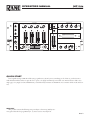
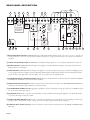
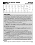
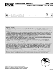
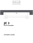
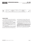
6
2
6
-2
2
6
6
8
6
8
MAX
MAIN
OL
MIC LEVEL
MIN
4
MIN MAX
AUX MIC LEVEL
2
4
MIN MAX
BASS
-6
MIN MAX
MID
-6
-2
ENGAGE
MIC
2
2
MIN MAX
TREBLE
-6
-2
MIC CONTROL
ENGAGE
3
4
CUE
A
F 60
0
0
4
6
8
10
2
1
2
4
6
8
10
ASSIGN
2
CUE
1
SOURCE CONTROL
10
0
2
8
0
0
CUE
0
2
4
6
8
10
6
4
4
6
ACTIVE CROSSFADER
2
4
6
8
10
2
4
6
8
10
2
2
8
TM
3
0
10
0
2
4
6
8
10
LINE 1 LINE 2
LINE 1 LINE 2
LINE 4 LINE 5
AUX/ PH 1
LINE 3 AUX/ PH 2
LINE 3 PH/ AUX 3
LINE 6
B
CUE
0
2
4
6
8
10
1
4
3
ASSIGN
2
0
2
4
6
8
10
LINE 4 LINE 5
LINE 6
LINE 3
4
ENGAGE
LOOP
10
8
2
0
4
10
6
0
2
4
6
8
10
8
MASTER LEVEL
0
2
4
6
8
10
0
6
BOOTH LEVEL
2
4
ZONE LEVEL
2
0
4
10
6
RIGHT
MAX
2
6
-6
MID
MAX
2
6
8
6
CUE
2
-6
-7
-5
-3
-1
PAN
PGM
2
6
STEREO
0
MONO
2
+5
6
CUE LEFT /
PGM RIGHT
CUE / PGM
+1
+3
MIN
MAX
HI-MID
-2
PROGRAM EQUALIZER
PEAK PROGRAM METER
MIN
-2
HEADPHONE CONTROL
-20 -15 -10
BASS
LEFT
MIN
-2
LEVEL
ENGAGE -6
EQ
+8
-6
2
dB
POWER
MIN
MAX
TREBLE
-2
6
MIXER
MP 24z
MP 24z
CLUB MIXER
IMPORTANT SAFETY INSTRUCTIONS
For the continued safety of yourself and others we recommend you
read the following safety and installation instructions. Keep this
document in a safe location for future reference. Please heed all
warnings and follow all instructions.
Do not use this equipment in a location where it might become
wet. Clean only with a damp cloth.
This equipment may be installed in an industry standard equipment
rack. We recommend that all mounting holes be used, providing
the best physical support. The equipment may be used as a table
top device, although stacking of the equipment is dangerous and
not recommended.
Do not directly block any of the ventilation openings. If rackmounting, please provide adequate ventilation. Equipment may be located
directly above or below this unit, but note that some equipment
(like large power amplifiers) may cause an unacceptable amount of
hum or may generate too much heat and degrade the performance
of this equipment.
Protect the power cord and plug from damage caused by being
walked on or pinched. Protect the line cord, where it exits the
unit, from excessive strain. Only use attachments and accessories
specified by Rane.
Unplug this equipment during lightning storms or when unused
for long periods of time.
Refer all servicing to qualified service personnel. Servicing is required
when the apparatus has been damaged in any way, such as power
supply cord or plug damage, spilled liquid, fallen objects into an
opened chassis, exposure to rain or moisture, a dropped unit, or
abnormal operation.
108385
OPERATORS MANUAL
MP 24z
DJ MIXER
MIC CONTROL
-2
SOURCE CONTROL
-6
PROGRAM EQUALIZER
LINE 1 LINE 2
LINE 1 LINE 2
LINE 4 LINE 5
AUX/ PH 1
LINE 3 AUX/ PH 2
LINE 3 PH/ AUX 3
LINE 6
2
LINE 4 LINE 5
LINE 3
LINE 6
LOOP
CUE
CUE
CUE
1
2
CUE
2
3
10
10
10
10
10
10
10
10
6
8
8
8
8
8
8
8
8
6
6
6
6
6
6
6
6
6
MIN
6
0
10
4
4
4
4
4
4
4
4
2
2
2
2
2
2
2
2
2
-6
MAX
-2
6
MIN
BASS
2
-2
-6
6
MAX
MIN
MAX
HI-MID
MID
2
-6
6
MIN
MAX
TREBLE
8
PEAK PROGRAM METER
10
10
8
8
6
6
4
4
2
2
0
0
-20 -15 -10 -7
6
8
MIN MAX
AUX MIC LEVEL
2
4
-2
LEFT
MIN MAX
BASS
4
ENGAGE -6
BOOTH LEVEL
4
2
2
-6
4
-2
EQ
10
2
MIN MAX
MID
2
8
0
6
-2
6
2
MIN MAX
TREBLE
-2
4
ENGAGE
6
-6
ZONE LEVEL
6
0
8
0
0
0
0
ACTIVE CROSSFADER
MAX
MAIN
OL
MIC LEVEL
0
0
2
3
0
4
2
4
6
8
10
F 60
B
1
2
3
4
0
+1
+3
+5
+8
dB
MIXER
HEADPHONE CONTROL
4
6
0
10
2
CUE / PGM
2
STEREO
ENGAGE
2
A
-1
MP 24z
0
ENGAGE
MIC
ASSIGN
-3
TM
MIN
1
-5
RIGHT
10
8
6
4
2
0
ASSIGN
MASTER LEVEL
8
LEVEL
6
6
CUE
PAN
PGM
POWER
MONO
CUE LEFT /
PGM RIGHT
QUICK START
Don't! Quick-starting an MP 24z is like trying to quick-start a 747. It's just not something you do. Trust us, you don’t want to
make mistakes with this sucker. So just this once—please—we highly recommend you read this entire manual: front-to-back, every
single page, every single word. It will familiarize you with the many intricacies of the MP 24z, not to mention all the nooks and crannies.
WEAR PART
This product contains the following wear part subject to the ninety (90) day warranty period described on page Warranty-1: (1) Active Crossover Assembly F 60.
Manual-
FRONT PANEL DESCRIPTION
12
4
2
MIC CONTROL
-2
LOOP
ZONE LEVEL
EQ
4
ENGAGE
CUE
CUE
CUE
1
2
2
8
0
CUE
3
-2
4
6
10
10
10
10
10
10
10
10
0
10
8
8
8
8
8
8
8
8
2
ENGAGE -6
10
2
MIN MAX
MID
-2
6
MIN
2
-6
MAX
-2
6
MIN
BASS
2
-2
-6
6
MAX
MIN
MAX
HI-MID
MID
2
-6
6
MIN
MAX
TREBLE
8
2
-6
6
PEAK PROGRAM METER
LEFT
MIN MAX
BASS
6
4
6
6
6
6
6
6
6
10
10
8
8
6
6
4
4
2
2
0
0
-20 -15 -10 -7
6
2
8
MIN MAX
AUX MIC LEVEL
4
6
2
8
4
4
4
4
4
4
4
4
2
2
2
2
2
2
2
2
0
0
0
0
0
0
0
0
ACTIVE CROSSFADER
MAX
MAIN
OL
MIC LEVEL
1
2
3
0
4
2
4
6
8
10
F 60
B
1
2
3
4
10 9 5
0
+1
+3
+5
+8
dB
MIXER
HEADPHONE CONTROL
4
6
2
6
-1
2
CUE / PGM
2
STEREO
ENGAGE
MIC
A
-3
TM
ENGAGE
ASSIGN
-5
RIGHT
MP 24z
MIN
11
17
BOOTH LEVEL
4
6
-2
6
2
MIN MAX
TREBLE
-2
18
PROGRAM EQUALIZER
LINE 4 LINE 5
LINE 3
LINE 6
6
-6
16
SOURCE CONTROL
LINE 1 LINE 2
LINE 1 LINE 2
LINE 4 LINE 5
AUX/ PH 1
LINE 3 AUX/ PH 2
LINE 3 PH/ AUX 3
LINE 6
2
-6
15 13
10
8
6
4
8
3
2
0
ASSIGN
MASTER LEVEL
7
14
8
0
LEVEL
10
6
6
CUE
19
PAN
PGM
20
POWER
MONO
CUE LEFT /
PGM RIGHT
21 22
1
23
1 POWER “ON” indicator: Illuminates anytime the MP 24z is connected to an appropriate power source (see k, Rear Panel).
2 SOURCE CONTROL selectors: Provide Input selection between the various Phono and Line Inputs for their respective mixing
channels.
3 Input channel faders: Control the relative Levels of each of the four Input mixing channels.
4 Channel CUE selectors: Engaging any single or combination of CUE pushbuttons sends any program present at the respective
channel’s SOURCE CONTROL selector to the Headphone Cue section. The yellow LEDs adjacent to each CUE select button
illuminate when the switch is engaged.
5 CROSSFADE ENGAGE switch: Activates the CROSSFADER and disables manual mixing capabilities. The adjacent green LED
illuminates whenever the Crossfader is active.
6 Left-hand CROSSFADE ASSIGN switch: Assigns the left side of the Crossfader to any of the four Input channels when the
Crossfader is activated by its ENGAGE switch.
7 Right-hand CROSSFADE ASSIGN switch: Assigns the right side of the Crossfader to any of the four Input channels when the
Crossfader is activated by the ENGAGE switch.
8 ACTIVE CROSSFADER: Controls the Levels of any two channels assigned to it by the left and right Crossfade ASSIGN
switches when the ENGAGE switch is activated. The entire Crossfader assembly is replaceable from the front panel without disassembling the entire unit. (See Service Information on page Manual-9.)
9 ENGAGE MIC switch: Enables the Microphone Inputs to feed the Booth, Zone, and Main Outputs. The adjacent red LED
flashes whenever the ENGAGE MIC switch is down and locked. This switch also activates a “ducker” circuit in the Booth
Output.(SeeFront Panel t and Rear Panel p.)
0 MAIN MIC LEVEL control: Sets the Level of the balanced low impedance MAIN MIC Input.
q AUX MIC LEVEL control: Sets the Level of the unbalanced high impedance AUX MIC Input, often used for wireless mics.
w Microphone equalization controls: Adjust the frequency contour of both Microphone Inputs. They have no effect on any other
program material.
Manual-
e LOOP ENGAGE switch: Controls the Switchable Effects Loop; pressing it to its down and locked position routes the main signal
through the processor attached to the SWITCHABLE LOOP connectors on the rear. (See Rear Panel w and e.)
r MASTER LEVEL fader: Determines the program and mic level at the Main Outputs. Unity gain is approximately “4.5”.
t BOOTH LEVEL control: Adjusts the program and mic level at the Booth Outputs. Unity gain is approximately “6.5”. This Output utilizes a “ducking” circuit, reducing the mic level when the MIC ENGAGE switch is pressed. (See Rear Panel p.)
y ZONE LEVEL control: Adjusts the program and mic level of the Zone Outputs. Unity gain is approximately “6.5”.
u PROGRAM EQUALIZER controls: Contour the frequency response of the program at the Main, Booth and Zone Outputs.
This is not designed to be the only equalizer in the system, this is intended to provide EQ between varying program materials.
i PROGRAM EQUALIZER ENGAGE switch: Enables the Program Equalizer to function when pressed in. The Equalizer is
bypassed in the out position.
o HEADPHONE LEVEL CONTROL: Clockwise rotation of this rotary control increases the headphone drive level.
p HEADPHONE PAN CONTROL: Serves two purposes…In the STEREO mode it changes the relative levels of the Cue and
Program mixed together in both earcups. In the MONO mode it changes the balance between the Mono Cue in the left ear cup
and the Mono Program in the right.
a HEADPHONE CUE mode switch: In the up position, this switch feeds Stereo Program and Cue to both earcups, in the
down position the Headphone circuit provides Mono Cue to the left ear and Mono Program to the right.
s HEADPHONE output jack: A tip-ring-sleeve stereo jack provides for the insertion of stereo headphones.
d PEAK PROGRAM METER: provides a visual indication of program output voltage. The calibration of the indication is user
adjustable. (See Rear Panel 6.)
Fader Cleaning
With heavy use in harsh environments, the faders may need
lubrication. This treatment extends longevity and can make used
faders as good as new. The fader assembly must be removed from
the MP 24z for proper cleaning. We recommend any of the following cleaning solutions:
Caig DeoxIT FaderLube F100 spray lubricant (www.caig.com)
Caig DeoxIT FaderLube F5 spray cleaner (www.caig.com)
CRC 2-26 (www.crcindustries.com)
Order CaiLube MCL® from:
CAIG Laboratories, Inc.
12200 Thatcher Ct.
Poway, CA 92064
Phone 858-486-8388
Fax 858-486-8398
www.caig.com
CLEANING INSTRUCTIONS
A. Fader assembly removal
1. Remove (2) 3mm screws.
2. Draw fader assembly out through hole.
3. Remove ribbon cable.
B. Fader cleaning
1. Hold the fader assembly away from the mixer.
2. Position the fader at mid-travel.
3. Spray cleaner/lubricant into both ends of the fader.
4. Move the fader over its full travel back and forth a few times.
5. Shake excess fluid from the fader assembly.
6. Wipe off excess fluid.
Manual-
REAR PANEL DESCRIPTION
21
4
ZONE OUTPUT
L
R
8
11
7
EQ
RANGE
TAPE OUT
SYSTEM
MONO
L
13 12
14
15
23
MAIN EFFECTS LOOP
24
SWITCHABLE LOOP
PH 3
L
R
L
R
L
L
R
R
RETURN
RETURN
SEND
MONO *
SEND
RETURN
SEND
RETURN
SEND
L
AUX 2
AUX 1
USING INTERNAL RIAA DEFEAT JUMPERS
L
L
L
R
L
±8dB
R
MONO *
UNBALANCED
±4dB
PRE LOOP
MAIN OUTPUTS
* MONO OUTPUTS
CAUTION
DO NOT UNDER ANY CIRCUMSTANCE
"STORE" PHONO SHORTING PLUGS
IN TAPE OUT JACKS. THIS WILL
SHORT SIGNAL PATH TO GROUND
CAUSING A LOW DISTORTED SIGNAL
TO ALL OUTPUTS. INSTALL IN
UNUSED INPUTS ONLY.
R
LINE 6
POST LOOP
PLUGGING ONLY INTO
LEFT YIELDS L+R
OUTPUT. PLUGGING
INTO BOTH YIELDS
STEREO OUTPUT.
L
MONO *
L
BOOTH
OUTPUT
UNBALANCED
BALANCED
OUTPUT
1: COMMON
2: POSITIVE
3: NEGATIVE
CASE: CHASSIS
DO NOT SHORT
PIN 3 TO GND!
USE ONLY PIN 2
AND PIN 1 FOR
UNBALANCED
SYSTEMS
FULLY
BALANCED
R
R
R
LINE 5
R
AUX 3
LINE 4
PH 2
R
LINE 3
LIGHT CONTROL OUTPUT
LINE 2
MAIN
MIC
MP 24z
RANE CORP.
MIC
1: COMMON
2: POSITIVE
3: NEGATIVE
CASE: CHASSIS
MONO
TRANSFORMER COUPLED
AUX
MIC
(HI-Z ONLY)
N108
USE FOR
WIRELESS
MICS
L
0
dB
MAX OUTPUT
GAIN REDUCTION
UNBALANCED
SIG GND
CHASSIS
750mA
GND
CLASS 2 EQUIPMENT
6
0
10
MIC
LOOP
TIP=SEND
RING=RETURN
PHANTOM
POWER
+15V
8
LIGHT OUTPUT LEVEL
BOOTH
DUCKER
5V 4V 3.5V
2.5V
6V
1.7V
10V
1V
OFF 0.6V
LIFT
28 27 26
4
2
R
POWER
PH 1
GROUNDING POST
-6
-22
LINE 1
ACTIVE
DEFEAT
METER SENSITIVITY ADJUST
3
5
1
6
2
9
10 25
18 20 19 17 16
1 BALANCED MAIN OUTPUT connectors: Provide a fully balanced Main Output signal—pin 2 is (+), pin 3 is (–) and pin 1 is
signal ground. Pin 3 must never be grounded for unbalanced operation. Use only pin 2 as hot and pin 1 as return for any unbalanced
operation.
2 UNBALANCED MAIN OUTPUT connectors: Provide Main Output signals on ¼" TS (tip-sleeve) unbalanced connections.
3 BOOTH OUTPUT connectors: The Left Output only supplies a mono Booth Monitor Output; connecting to both Left and
Right provides a stereo Output.
4 ZONE OUTPUT connectors: The Left Output only supplies a mono Zone Output, connecting to both Left and Right provides
a stereo Output. The Zone Outputs are located Post-EQ, which includes the Microphone Output. An internal jumper block programs the Zone to Pre-EQ (and no mic) if required. (See Service Information on page Manual-9.)
5 MAXIMUM OUTPUT GAIN REDUCTION control: Decreases the maximum Level of the balanced and unbalanced MAIN
OUTPUTS of the MP 24z as it is rotated counter-clockwise.
6 METER SENSITIVITY ADJUST: Clockwise rotation decreases the full-scale sensitivity of the PEAK PROGRAM METER, as
indicated by the full-scale voltage calibrations around the control.
7 SYSTEM MONO/STEREO switch: Engaging this pushbutton converts all Outputs (except tapes and loops) to MONO, regardless of the nature of the Input signals.
8 EQ RANGE switch: In the out position, the maximum boost/cut available from the Program Equalizer is ±8 dB. In the switch’s
in position, this range is reduced to ±4 dB.
9 LIGHT CONTROL OUTPUT jack: Provides a transformer-coupled mono program signal for use by a lighting controller’s trigger input. This is a balanced ¼" output—the tip is positive, the ring is negative and the sleeve is floating.
0 LIGHT OUTPUT LEVEL attenuator: Counter-clockwise rotation reduces the Output Level at the LIGHT CONTROL OUTPUT jack.
Manual-4
q TAPE OUT jacks: One pair of RCA jacks provides pre-EQ, pre-LOOP Program Outputs. The other pair supplies pre-EQ, postLOOP Program Outputs. The microphone signals are not available at these Outputs, however they are selectable using an internal
jumper block. (See Service Information on page Manual-9.)
w SWITCHABLE LOOP SEND jacks: Use these ¼" unbalanced Left and Right Outputs for driving the inputs of a processor
activated by the LOOP button (front panel e).
e SWITCHABLE LOOP RETURN jacks: Use these ¼" unbalanced Inputs for receiving the outputs of the above processor.
r MAIN EFFECTS LOOP SEND jacks: Provide drive to the inputs of a signal processor which is not to be switched from the front
of the mixer. Connecting only to the LEFT Effects Send provides a mono Output; connecting to both LEFT and RIGHT provides a stereo feed. These are ¼" TS (Tip-Sleeve) unbalanced connections.
t MAIN EFFECTS LOOP RETURN jacks: Receiving the processed signal generated from the Main Effects Loop SENDs. These
are ¼" TS unbalanced connections.
y Balanced MAIN MIC Input jack: Connects a balanced microphone of any impedance, either dynamic or condenser.
u Unbalanced high-impedance AUX MIC Input jack: Connects an unbalanced wireless or other high-impedance mic.
i MIC LOOP jack: Inserts external signal processing in the microphone circuit only. This is a ¼" TRS tip-send, ring-return configuration. This feature does not affect the operation of the Main Program channels.
o PHANTOM POWER switch: Engaging this pushbutton applies +15 V Phantom Power to the balanced (XLR) MAIN MIC
Input only. It has no effect on the Aux Mic Input. The adjacent red LED illuminates whenever Phantom Power is active.
p BOOTH DUCKER switch: When in the ACTIVE position, the ENGAGE MIC switch (front panel 9) reduces the Microphone level at the Booth Outputs. When in the DEFEAT position, Microphone level is not reduced.
a AUX/PHONO input jacks: Use these stereo Phono Input pairs for connecting any moving-magnet type cartridges to the mixer.
Internal jumpers are provided to convert these into Line level Inputs (See Service Information on page Manual-9). AUX/PH 1 and
AUX/PH 2 jumpers are set at the factory for PHONO. The PH/AUX 3 jumper is set at the factory for a LINE level input. When
these jumpers are set to PHONO, never use these Inputs for any other purpose due to the amount of gain and RIAA equalization
present. Any unused Phono Input should have the Phono Shorting Plug installed to prevent interference from an outside source. Do not
put any of the Phono Shorting Plugs into the Tape Out jacks, as this will short all the Outputs.
s PHONO/AUX 3 input jacks: As in a above. Note this Input is shipped with the internal jumpers in the LINE position.
d LINE 1 & 3 through 6 Input jacks: Are suitable for all line-level devices such as the audio outputs of DVD players, CD players,
iPods, radio tuners, drum boxes, keyboards, etc. These RCA connectors pairs are unbalanced, line-level Inputs only.
f LINE 2 Input jacks: Are a fully balanced, ¼" TRS (Tip-Ring-Sleeve) line Input. The tip of the jack is (+), the ring is (–) and the
sleeve is ground.
g GROUNDING POST terminal: Provided to facilitate your hum chasing, buzz eliminating experiments. Its purpose is to provide
a place to connect those extra wires coming out of the turntables.
h Chassis ground point: Since the MP 24z does not get chassis ground through the AC cord, this point is provided in case your
system does not have another earth ground such as the rack rails. A #6-32 screw and toothed washer is provided for chassis
ground. See Chassis Grounding on page Manual-8 for details.
j GROUND LIFT SWITCH. Separates chassis ground from signal ground. Normally, this switch should be in the LIFT position.
In some circumstances, moving it to the opposite position eliminates stubborn hum and buzz problems. If you are tempted to
move this switch with your power amplifiers turned on and cranked up, don’t. Always turn your system levels down before changing
your grounds around and then bring them up slowly.
k POWER input connector: No, this is not where Commissioner Gordon plugs in his Bat-phone, in fact it is not a telephone jack at
all. The MP 24z uses an 18 volt AC center-tapped transformer. Use only a model RS 1 remote AC power supply approved by Rane.
Manual-5
MP 24z CONNECTION
Even though the system variations are limitless in most applications where the MP 24z is used, an installer must follow
some basic interconnect guidelines. Unfortunately, even though
the system and the primary components such as mixers, processors and amplifiers are of commercial grade, most of the source
components, i.e. turntables, disc players, tape decks and so on
are consumer grade, with consumer interconnect limitations.
Therefore, on the input side of the MP 24z, RCA connectors
will prevail with unbalanced lines thereto attached. It is recommended, for no scientific reason, that the turntable furthest to
the left be connected to Phono 1, and proceed from left to right
with Phono 2 and then Phono 3, if used. See Service Information
on page Manual-9 to convert any PHONO level Input into a
LINE level Input.
When determining which Line Inputs to use for what, the
process becomes a bit more difficult. Obviously, if one of the line
devices feeding the MP 24z is of the commercial variety sporting balanced outputs, use Line 2 for this due to its unique ability
to accept such foreign substances. The rest of the assignments
are pretty much a matter of what you want to appear where on
the source switches. As you can see, Lines 1 through 3 appear
only on Input Channels 1 and 2; Lines 4 through 6 appear only
on Input Channels 3 and 4. So the layout will depend on how
heavily you will use the Phono Inputs and how many line level
devices you will be using.
On the Output side, things are a bit less restrictive. On the
MAIN OUTPUTS you have been given a choice between XLR
balanced and ¼" unbalanced. Which you use should be derived
from some consideration of how far the cable has to run from
the mixer to the next component, how much ambient noise there
is in the local atmosphere (Radio Moscow in the next building,
36,000 SCR controlled light dimmers in the next rack), and any
other possible encumbrance on the quality of the audio inside
the jacket. Most experienced installers and users of commercial
sound equipment have a good handle on which to use in a given
situation. The general rule is: if the Output from the MP 24z is
running longer than 10 feet (3 meters), use balanced cables. If
the input to your system equalizer, crossover, or power amplifier
is balanced, go balanced. If you keep the cable length short and
your destination has unbalanced inputs, you can probably get
away with using the ¼" unbalanced connectors.
The TAPE OUTPUTS are unbalanced RCA connectors;
the assumption being that most readily available tape recording
equipment such as would be used in a club situation would be
of similar type. Simply determine whether you want the signal
processing in the Effects Loops to have an effect on the recording
being made and connect the record inputs (left and right) to the
appropriate PRE-LOOP or POST-LOOP TAPE OUTPUTS.
These Tape Outputs do not contain any signal from the Microphone section. If you need to record the Mic, use the Unbalanced
Main Outputs, Zone Output, or the Booth Output with the
Booth Ducker circuit defeated. (If none of these are available, see
Service Information on page Manual-9 for internal jumper changing instructions.)
Manual-6
The front panel switchable LOOP is for stereo devices only,
so consider which effects are connected where. Some processors, such as delays and reverbs, have only one mono input and
two outputs. This is accommodated automatically by using the
MONO Output of the MAIN EFFECTS LOOP.
The Zone Outputs and the Booth Outputs are the automatic mono/stereo type. If mono is required, simply connect
only to the LEFT OUTPUT. Inserting a plug into the RIGHT
OUTPUT automatically renders it stereo. All of these Output
connectors are unbalanced. Attempting to run TRS balanced on
any of these results in an open leg on the receiving component and
causes problems.
This is a good place to discuss the problems encountered in
connecting the MP 24z to all of the different types of cables and
connectors that one finds when basing a system on consumer
goods (the pieces of equipment with the RCA connectors),
commercial audio products (¼", XLR etc.), and no telling what
else. In consumer audio devices, one rarely finds ground-lift
capabilities, or any of the other hum prevention devices normally
provided on commercial equipment. Chassis ground and signal
ground are normally the same thing, a situation which may cause
problems when the two species get on the same bus.
The best we can do to try to help you eliminate hum, oscillations, or other stray characters from your system is to tell you
to experiment. If you think lifting the ground on the MP 24z,
crossovers, equalizers or power amplifiers might help, go ahead
and try it. There is science involved in de-humming a system,
however it is sometimes faster to just experiment. Occasionally, directly grounding the chassis of the mixer to the power
amplifiers with a large gauge wire helps. And by the same token,
isolating the two when they are installed in the same rack may
have a quieting effect. A word of caution: Don’t do anything with
Level controls up, power on, or under any condition that could cause
damage to delicate loudspeakers and ears. Make your changes with
the system off, then power up carefully to make sure you haven’t
made matters worse. Bring up Level controls slowly and with
great caution. Surprises are nice on birthdays and Christmas,
and rarely any other time.
If hum problems only exist on the Phono Inputs, there is
always a possibility for experimental troubleshooting at this end
also. Experience has shown that just because the manufacturers
put ground wires on them, they are not always connected! Some
turntables even have two ground wires, one for the tone arm and
one for the chassis. Sometimes only one of these should be connected for optimum signal-to-noise, sometimes both, sometimes
none. The rule is: “Whatever works, works.”
OPERATING INSTRUCTIONS
INITIAL OPERATION
Operation of the MP 24z is fairly straightforward, deviating
only slightly from other products of its type. Assuming at least
one turntable is connected and assigned to PHONO 1, operation consists of the following: Make sure all faders are set to zero,
the MIC, LOOP, EQ, and ACTIVE CROSSFADER are all
disengaged, (switches out) and that all rotary LEVEL controls are
either fully counter-clockwise or in their center detents, whichever applies. Select PHONO l on Input Channel 1. Simultaneously raise the Channel 1 fader and the MASTER LEVEL fader.
Before much travel is reached on the faders, the results should
be heard. If not, shut everything down and recheck connections,
power to the mixer (look for the yellow POWER light) and
ancillary devices (EQs, crossovers, amplifiers, etc.)
Once an output is established from the turntable, go ahead
and try everything else. Assign all Inputs to the Channels they
will be used, and test the system. Once all sources are set as
desired, proceed.
REAR PANEL ADJUSTMENTS
There are some controls on the rear panel which need to be
set. Set the METER SENSITIVITY ADJUST so the system
is at maximum level, (usually just short of amplifier clipping).
Run the system up to this maximum level and turn the METER
SENSITIVITY ADJUST so that the highest peaks on the PEAK
PROGRAM METER occasionally hit the +8 dB indicator. This
warns the operator that further pressure on the throttle will
overdrive the system.
At this point check the MAXIMUM OUTPUT GAIN REDUCTION control so that with the MASTER LEVEL at “10”,
the meter responds as it did in the previous step. This would be
a good time to make the adjustment. This may be accomplished
by turning the rear panel MAX OUTPUT GAIN REDUCTION adjustment all the way down, pushing the MASTER
LEVEL fader all the way up, setting a normal mix level on the
Input fader, and then turning up the MAX OUTPUT GAIN
REDUCTION adjustment on the rear until the required output
level is attained. In some cases, make this adjustment with both
the Source Level and the MASTER LEVEL faders all the way
up. This is acceptable only if sources can be adjusted such that
they all have equal output before they reach the Input of the
MP 24z. If this is not possible, full system drive will not come
from some components. To accomplish this feat, use identical
cartridges in all turntables so the phono levels are all the same.
Having done all of this it is possible to use the MAX OUTPUT
GAIN REDUCTION on all of your sources.
The other rear panel adjustment that should be made at this
time has to do with the maximum deviation to the frequency response of the system left to the operator. This is controlled by the
EQ RANGE switch. In the out position, the range of all of the
EQ controls is ±8 dB. In the in position, this range is reduced
to ±4 dB. The latter is considered safer in situations where taste
makes waste—in drivers, that is.
THE HEADPHONE CONTROL (CUE) SYSTEM
To use the HEADPHONE CUE System, signal must be
present at one of the Inputs. (Well, at least you do to make sure
it works.) Depressing the CUE switch for the respective Input
channel presents this signal to the Headphone Cue amplifier.
An LED illuminates next to the CUE switch, attesting to the
fact that it was indeed pushed down. Now select how to listen to
it — Mono Cue in one ear, Mono Program in the other, Stereo
Program in both ears, or Stereo Cue in both ears. The STEREO/
MONO CUE switch allows this flexibility. To vary the level
between Cue and Program, rotate the HEADPHONE PAN
control in the desired direction. Counter-clockwise rotation increases the Cue Level, clockwise rotation increases the Program
Level. The overall volume of all of this is then controlled by the
rotary HEADPHONE LEVEL control.
USING THE ASSIGNABLE ACTIVE CROSSFADER
Active Crossfader™ technology combines state of the art voltage controlled amplifier design with a professional quality crossfader control. This combination sets new standards for performance, reliability and serviceability. Virtually all crossfader noise
is eliminated. Channel to channel crosstalk is greatly reduced
and the off isolation of the faded channel is greatly increased. Active Crossfader technology dramatically increases the service life
of the crossfader. In the unlikely event of crossfader failure, there
is no loss of signal. If a crossfader becomes rough or noisy, it may
be “hot-swapped” during a performance with no interruption
of the audio signal. Simply use the input faders to set the audio
levels while the crossfader is out of service.
For normal operation, press the Crossfade ENGAGE switch.
The green LED next to the switch illuminates. The Crossfade
ASSIGN switches determine the two Input channels to be mixed
by the Crossfader. As an example, assume the left ASSIGN
switch is set on 1 and the right ASSIGN switch is on 2. This
activates both mix faders on Channels 1 and 2. Their outputs,
however, are under the control of the Crossfader. When in its
left-most position, only Channel 1 appears at the Outputs. Both
Channels are present in equal levels in the when the Crossfader is
brought to the middle, and only Channel 2 is heard once the far
right is reached.
The contour of the Crossfade has been optimized for contemporary use. However, the mix of the two input signals will
have an impact on volume level as you fade from one input to the
other.
Once crossfaded to Channel 2, maybe cue up some video and
put the audio on Channel 4. Hard to do? No way. Simply pull
the Channel 1 fader to zero, set the ASSIGN switch on the left
of the Crossfader to Channel 4, Cue up 4, set the level on fader 4
and Crossfade into it. We realize that it’s a bit strange to Crossfade from 2 to 4 by sliding the fader to the left, however it’s just
an unavoidable oddity caused by having so much flexibility.
Manual-7
MICROPHONE OPERATION
To use the mic, connect it to the appropriate connector, and
set the PHANTOM POWER switch to the desired mode (it’s
a good idea to have the Phantom Power in the on position for
condenser mics, off for dynamics). Leave the MASTER LEVEL
fader in roughly the same location as it was for the music that’s
been playing, press the MIC ENGAGE switch and slowly adjust
the MAIN MIC (or AUX MIC) LEVEL. Once this has been
accomplished, the tonal balance may be adjusted via the MIC
EQ controls located above the LEVEL controls. Modifying the
sound of the mic in this way won't affect the EQ of the music in
the system. The two Equalizer sections (Mic and Program) are
totally independent. When the microphone is not in use, release
the MIC ENGAGE switch again to its upward position. When
the switch is down, the red LED flashes. When off, the LED will
be out. If the microphone preamp becomes overloaded, the red
LED Overload light illuminates. If this is a problem, lower the
appropriate MIC LEVEL control and increase the level of the
MASTER LEVEL fader to restore desired microphone level.
MONO OPERATION
There may be situations where a mono output signal is
preferable to a stereo output. If this is the case, mono outputs
may be obtained on all of the Outputs (Master, Booth, Zone) by
engaging the SYSTEM MONO switch on the rear panel. When
engaged, the SYSTEM MONO switch sums the Left and Right
buses together. In this situation, if only one of the stereo Inputs
on any of the three Phono or six Line sections is driven, the applied signal appears in equal quantities at both Left and Right
OUTPUT connectors.
USING THE LIGHTING CONTROL OUTPUT
The mono LIGHT CONTROL OUTPUT allows use of
lighting systems designed to be triggered from an audio source.
A LIGHT OUTPUT LEVEL control adjusts the output level
appropriate for the lighting controller. There appears to be a wide
variety of sensitivities in different brands of controllers, therefore
some adjustment is likely required. In the full CW position of
the LIGHT OUTPUT LEVEL control, the signal delivered
is amplified 20 dB relative to the pre-master fader level. If this
is excessive, CCW rotation of the LIGHT OUTPUT LEVEL
control decreases the drive amount. None of the LEVEL controls
past the Input Channel faders affect this drive level.
Manual-8
BOOTH AND ZONE OUTPUTS
The ZONE OUTPUT is an additional Stereo Output with
it’s own ZONE LEVEL control that can be routed to an amplifer that feeds the bar, another tape recorder, etc. This output
is Post-EQ, which means also that the mic is heard from the
Zone Outputs along with any Program EQ changes (This can be
changed with an internal jumper block). The BOOTH OUTPUT operates much the same way, with an added feature: When
the ENGAGE MIC switch is activated, the gain of the BOOTH
OUTPUT “ducks” down 13.5 dB to prevent feedback from the
booth speakers. If this Output is used for something else and this
feature is undesired, a BOOTH DUCKER DEFEAT switch is
provided on the rear panel. Be sure this switch is in the ACTIVE
position if booth speakers are used.
SOME FURTHER HINTS
Set the Input Channel faders near their maximum levels to
preclude required excessive gain from the Output stage. Optimum noise performance is achieved by running the majority of
the gain on the Input stages. Taking the least amount of gain on
the Output stage ensures that the system doesn’t have to amplify
the unavoidable noise generated by the input buffers and summing amplifiers.
IMPORTANT NOTE
CHASSIS GROUNDING
The MP 24z is supplied with a rear mounted ground-lift
switch. The unit is shipped with this switch in the “grounded”
position, tying circuit ground to chassis ground. If after hooking
up your system it exhibits excessive hum or buzzing, there is an
incompatibility in the grounding configuration between units
somewhere. Here are some things to try:
1. Try combinations of lifting grounds on units that are supplied
with ground lift switches or links.
2. If your equipment is in a rack, verify that all chassis are tied to
a good earth ground, either through the line cord grounding
pin or the rack screws to another grounded chassis.
3. This units outboard power supply does not ground the chassis
through the line cord. Make sure that this unit is grounded
either to another chassis which is earth grounded, or directly
to the grounding screw on an AC outlet cover by means of a
wire connected to a screw on the chassis with a star washer to
guarantee proper contact.
Please refer to RaneNote “Sound System Interconnection”
(supplied with this manual and available at www.rane.com) for
further information on system grounding.