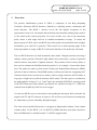
1
LHCb Project Document
EDMS No 948 074 V 1.0
Date: dd-mmm-2008
Page 1 of 23
Operational Procedure
OPERATIONAL PROCEDURES
FOR THE RICH DETECTORS
This document defines the procedures for the safe operation and maintenance of the RICH-1
and RICH-2 sub-detectors of the LHCb detector.
IMPORTANT:
The procedures described therein are in line with the safety rules and regulations at CERN
and have to be strictly followed.
Keywords: Safety, RICH, procedure
Prepared by:
Checked by:
Approved by:
Carmelo D’Ambrosio
Christoph Frei
Thomas Blake
Date: dd-month-2008
Neville Harnew
Olivier Callot,
Eric Thomas,
Werner Witzeling
Date: dd-month-2008
Date: dd-month-2008
Distribution:
Subdetector Group, Operations
LHCb Project Document
EDMS No 948 074 V 1.0
Date: dd-mmm-2008
Page 2 of 23
1.1.1.1 History of Changes
Version
Date
1.0
dd-mmm2008
Pages
Comments or description of changes
First version, draft 1
LHCb Project Document
EDMS No 948 074 V 1.0
Date: dd-mmm-2008
Page 3 of 23
Contents 1 OVERVIEW ......................................................................................................... 5 2 DESCRIPTION OF SPECIFIC SAFETY SYSTEMS AND INTERLOCKS .......... 6 2.1 Detector Safety System (DSS) ..................................................................................... 6 2.2 Experiment Control System (ECS) ............................................................................. 7 3 PROCEDURES FOR STANDARD OPERATION ............................................... 7 3.1 Instructions to be applied for safe starting up and shutting down of system ......... 7 3.2 Low voltage supply ....................................................................................................... 7 3.3 Silicon Bias .................................................................................................................... 8 3.4 High Voltage ................................................................................................................. 8 3.5 From the Control Room, procedures to be applied for safe operation of the RICH
detectors: ................................................................................................................................... 9 3.6 Run Control and Operation ...................................................................................... 11 3.7 Online Monitoring ...................................................................................................... 11 3.8 Typical DAQ errors and their solutions................................................................... 12 3.9 Standard Parameters for safe operation .................................................................. 13 3.10 Atmosphere in HPD enclosures ................................................................................ 14 3.11 Cooling of the HPD electronics ................................................................................. 15 3.12 Mirror alignment........................................................................................................ 16 4 PROCEDURES FOR ROUTINE MAINTENANCE ............................................ 16 4.1 Atmosphere in HPD enclosures ................................................................................ 16 4.2 Cooling of the HPD electronics ................................................................................. 17 4.3 Radiation Protection .................................................................................................. 17 4.4 Beam Pipe Protection ................................................................................................. 17 LHCb Project Document
EDMS No 948 074 V 1.0
Date: dd-mmm-2008
Page 4 of 23
5 PROCEDURES FOR SPECIAL INTERVENTIONS .......................................... 17 5.1 Replacing an ISEG HV supply .................................................................................. 17 5.2 RICH 2 - Access to HPD enclosures ......................................................................... 18 5.3 RICH 2 - Intervention on HPDs or its electronics................................................... 19 5.4 RICH2 - Access to the gas enclosure ........................................................................ 19 5.5 RICH2 - Closing of the gas enclosure ....................................................................... 20 5.6 RICH 1 ........................................................................................................................ 20 5.7 Replacing a fuse, Level-0 or Low Voltage Board .................................................... 20 5.8 Replacing a HPD ........................................................................................................ 21 6 APPENDIX A: STANDARD OPERATING PARAMETERS ............................. 22 LHCb Project Document
EDMS No 948 074 V 1.0
Date: dd-mmm-2008
Page 5 of 23
1
Overview
The particle identification system of LHCb is comprised of two Ring Imagining
Cherenkov Detectors (RICH) detectors, flanked by a tracking system, calorimeters and
muon detectors. The RICH 1 detector covers the full angular acceptance of the
spectrometer, from 10 to 300 mrad in the horizontal projection (the bending plane), and 10
to 250 mrad in the vertical projection. Two active media, very close to the interaction
point, ensure a wide angle and low to medium momentum coverage. To ensure the
physics goals of LHCb can be met RICH 2 provides positive kaon identification of higher
momentum, up to 100 GeV/c, particles. These tend to lie at small opening angles to the
beam pipe and the coverage of RICH 2 is therefore limited to 120 mrad times 100 mrad.
The two RICH detectors are built around the same model. Charged particles traversing a
radiator volume generate Cherenkov light which is then focused by a system of spherical
and flat mirrors onto planes of photon detectors. The position of hits on these planes is
then used to estimate the likelihood that the particle is, for example, a kaon rather than a
pion. The planes are made up from a total of 484 pixel Hybrid Photon Detectors (HPDs)
split across the two detectors. Each HPD contains a silicon pixel detector comprising 8192
elements which can be read out in two modes, either as single elements (ALICE mode) or
as groups of eight actively OR-ed elements (LHCb mode). The latter gives a resolution on
the photocathode of about 2.5 x 2.5 mm2 and is the standard (PHYSICS) operating mode
of the RICH detectors. Data readout is performed at a sustained average of ~1 MHz rate,
reduced from 40 MHz by LHCb level zero trigger.
As such, the RICHes are two closed boxes surrounding the beam pipe before and after the
magnet with TT and OT detectors in between. The two boxes are monitored continuously
for temperature, pressure, humidity and light integrity.
The front end of the RICH detectors is arranged as independent columns. Each column
contains either 14 (for RICH 1) or 16 (RICH 2) HPDs and their associated electronics.
Pairs of HPDs share L0 readout boards, LV and HV supply boards.
LHCb Project Document
EDMS No 948 074 V 1.0
Date: dd-mmm-2008
Page 6 of 23
2
Description of Specific Safety Systems and Interlocks
The safety protection system of the RICH detectors can be split into two parts. Actions
triggered directly by the RICH detector safety system (DSS) and those triggered by the
RICH Experiment Control System (ECS).
2.1
Detector Safety System (DSS)
The DSS concerns equipment protection and is described in detail in document
EDMS:830673. An overview of the DSS alarm matrix is provided in Figure 1. The DSS
provides protection for the racks, continuous monitoring of the cooling flow to the RICH
electronics, environmental monitoring of the HPD enclosures (through Pt100 sensor and
thermo switches). It also acts on the light-tightness of the enclosures through physical
switches and a light-leak detector 1 . If an alarm is raised the DSS system will directly cut
power to the racks.
Figure 1: Detector Safety System (DSS) alarm matrix.
1
For detailed instructions on the use of the light leak detection system see
https://lbtwiki.cern.ch/bin/view/RICH/RichPower/blac.pdf
LHCb Project Document
EDMS No 948 074 V 1.0
Date: dd-mmm-2008
Page 7 of 23
2.2
Experiment Control System (ECS)
The actions of the ECS system are complementary to, and deliberately overlap those of,
the DSS. In the advent of a DSS alarm the ECS system of the RICH will ramp down all of
the supply voltages in a controlled manner before the racks are interlocked. In addition the
ECS monitors:
•
the temperature of the LV regulators,
•
the current drawn by the CAEN silicon bias and Wiener Maraton supplies,
•
the cooling pressure.
The High Voltage daemon running on a credit card PC (CCPC) will act on the high
voltage supply if the high voltage goes under or over current (or voltage). The daemon
will only trigger the switching off of the column(s) concerned and HV can remain
supplied to over columns.
3
3.1
Procedures for Standard Operation
Instructions to be applied for safe starting up and shutting down of system
The front end of the RICH detectors is supplied with two low voltages (of 4.4V and
5.4V), a biasing voltage (for the HPDs pixel sensor) of 80V and a high voltage of up to
20kV. This single HV line supplies the three biasing voltages of the HPD electrodes via a
divider at the front end.
3.2
Low voltage supply
The Low Voltage power supply system is based around the Wiener Maraton
(EDMS:792758). Two of the component pieces are located in the RICH racks in D3
(PFCs and controller modules) whilst the front-end marathon boxes are located close to
the RICH detectors, on the balcony for RICH 1 (P1A05) and in the bunker for RICH 2
(racks T0A05 and T0A15). To power on the voltage system the power-on sequence is as
follows:
•
Switch on controller modules, located in 6U VME crates in D3C02 and D3C05.
The VME crates have ON/OFF switches. One on the power supply at the rear of
LHCb Project Document
EDMS No 948 074 V 1.0
Date: dd-mmm-2008
Page 8 of 23
the crate and the second on the main front-panel of the crate. When turned-on the
modules will start up automatically.
•
The PFCs (Power Factor Correction), rectifiers, should be switched on. These are
found in 4U racks (D3C02 and D3C05).
•
Switch on the Maraton boxes in racks P1A05 (RICH 1), T0A05 (RICH 2) and
T0A15 (RICH 2).
The control of the L0 boards at the front-end is performed via a SPECS slave on the
columns. Communication with the SPECS slave is performed by 32 DIM servers (running
on r1daq01w, r1daq02w, r2daq01w and r2daq02w machines). These need to be running
before the front-end can be configured and the LV regulators switched on.
3.3
Silicon Bias
The reverse bias voltage for the HPDs silicon pixel sensor is provided by the CAEN
SYS1527. The modules and patch panels are located in the following racks in D3: D3C02
(RICH 1) and D3C05 (RICH2). The following steps are required to power-on the CAENs:
•
The crates have two ON/OFF switches. One on the rear of the crate and a turn-key
switch on the front of the crate. The switch at the rear should be turned on and the
key turned to “local control”.
•
The channels on the patch panel should be enabled.
The power off sequences for the LV and the silicon bias are the reverse of the sequences
given above.
3.4
High Voltage
The HV for the front-end of the RICH detectors is provided by ISEG (CPn 200 504 24 10)
supplies, controlled and monitored by a pair of DACs and ADCs via an I2C bus connected
to a CCPC (credit card PC). The HV modules and their 24V DC supplies are located in
D3 (rack D3C06 for RICH 2 and D3C03 for RICH 1). Each ISEG contains a splitter to
supply the two half-columns of the front-end from a single HV supply. The control of the
HV is carried out through the CCPC and described in detail below. The HV control is
always on when power is supplied to the racks in D3. To enable the HV the user should:
LHCb Project Document
EDMS No 948 074 V 1.0
Date: dd-mmm-2008
Page 9 of 23
•
check the status of the light leak detector,
•
turn on the crate containing the CCPC and the 24V supply (D3C06 and D3C03),
•
build the ram disk and start the daemon on the CCPC (details on how to do this
can be found later in this document),
•
operate the HV through the PVSS panel.
The HV has three levels of readiness:
•
GO_STANDBY1, ramping the HV to 3kV,
•
GO_STANDBY2, ramping to 13kV,
•
GO_READY, that ramps directly to 18kV.
Under standard operating conditions GO_READY action should be used. 18 kV is
currently the standard operating voltage of the RICH detectors. The rate at which the HV
is ramped is controlled by PVSS; it should not exceed: 50 Vs-1 between 0 and 10 kV, 20
Vs-1 from 10 to 15 kV and 10 Vs-1 above 15 kV.
Ideally the HV should be ramped to 18kV and then left to stabilize for at least one hour
prior to data taking. If this is not possible the RICH detectors will see an increased noise
rate (due to charge settling effects).
If the HV is not responsive (or after a power cut) the user should check the status of the
HV daemon running on the CCPC. This daemon runs on the Linux machines r1hv01 and
r2hv02 for RICH 1 and 2 respectively. HVSetup will tell you if the daemon is running. If
the daemon is not running it can be started manually using the script
/group/rich/HV/hvcont_start_daemon.sh. If recovering after a power intervention then it
may also be necessary to re-build the disk image of the CCPC. This can be done using the
script /group/rich/HV/hvcont_create_ramdisk.sh
3.5
Procedures to be applied for safe operation of the RICH detectors:
The following procedures should be followed during operation of the RICH detector:
•
Check for DSS alerts and/or warnings.
•
Check that cooling is ON and that the cooling flow / pressure is adequate (this is
described later in this document).
LHCb Project Document
EDMS No 948 074 V 1.0
Date: dd-mmm-2008
Page 10 of 23
•
Check that Light Leak Detector is ON. The light leak detector triggers an interlock
of the HV system if the light level inside the RICH vessels exceeds 7.0 (arb. units).
This level is continuously monitored by a set of photomultipliers within the HPD
volume of RICH 1 and RICH 2. If the light exceeds 7.0 the HV will be interlocked
and the interlock will have to be manually removed from the Light Leak Detector
in D3C06 or 03 for RICH 2 and 1 respectively. This will also trigger a DSS alarm.
If any of these are in an ‘ERROR’ state they must be rectified before the RICH can
operate. They will also trigger a power down of the RICH detectors. In addition the
operator must check the status of the RICH on these panels:
•
RICH Overview,
•
HPD Environment.
•
CF4 and C4F10 environment.
There are separate panels for RICH 1 and 2 and are accessible from the G:\rich\shift
directory. It is particularly important to check the status of the LV and HV on the RICH
Overview panel. The HV on this panel is monitored through a protection board and
ELMB from the front end HV boards. Finally the FSMs have to be in taken status (no
SHARE nor RELEASE ALL) and resources allocated.
If the RICH is in a safe (READY) state, the RICH DCS can then be operated to
POWER_ON on the RICH electrons, providing both the LV and the silicon bias voltages
to the L0 boards and HPDs at the front end. During normal running the HV should be on
before the electronics is powered.
It is currently standard practice to not include the HV FSM in the full RICH (RICH 1 or
RICH 2) FSM tree. These should instead be taken at a lower level and locked out at the
level of the ECS projects. This ensures that HV control is not part of the general RICH
operation, i.e. HV should remain on and only be turned off for interventions on the
hardware.
The RICH can now be configured from the top most FSM and a run started.
LHCb Project Document
EDMS No 948 074 V 1.0
Date: dd-mmm-2008
Page 11 of 23
3.6
Run Control and Operation
There are a number of different recipes available for data taking:
•
PHYSICS (and PHYSICS|…). When operating the RICH a L0 bunch gap of 1
should ALWAYS be asserted.
•
ALICE. For operation of the HPDs with the smaller (62.5 um) pixel size. Note that
random triggers should not be used (i.e. use Calibration A or C triggers) and due to
the larger event size a bunch gap of 32 crossings should be used.
•
ALICE|MDMS. A special recipe designed for taking Calibration runs with the
RICH 1 magnetic distortion monitoring system. This will remove the MDMS light
bar from its parked position and step across the photon detector plane in 3515
steps. The light bar will be automatically parked when the run finishes. In all other
respects this recipe functions like the ALICE recipe.
PHYSICS is the standard recipe for data taking. Other recipes may be used during
detector commissioning but should not be used during normal operation.
3.7
Online Monitoring
RICH monitoring histograms can be viewed by following the standard procedure of:
•
opening the presenter by running startOfficalMonitor from any plus node,
•
selecting the RICH or the RICH 1 / 2 partition (during commissioning),
•
navigating to the RICH database page.
Histograms on this page are continuously updated by the RICH monitoring software
Panoptes. The monitoring histograms currently include hit maps of the four HPD planes
and the number of hit pixels per event. Error information is propagated from Panoptes to
the user via CAMERA a RICH specific tool for error communication, distribution and
logging. To start camera from a plus node: run the script setupMonitorring followed by
startCameraGui. When using the presenter or Camera it is important to have X11
forwarding properly enabled.
LHCb Project Document
EDMS No 948 074 V 1.0
Date: dd-mmm-2008
Page 12 of 23
A complete set of instructions can be found on the RICH operations twiki:
https://lbtwiki.cern.ch/bin/view/RICH/WebHome. Additional histograms are provided for
use by RICH data quality experts.
3.8
Typical DAQ errors and their solutions
There are two possible sources of DAQ errors during general operation: errors from the
L0 and errors from the UKL1 boards. In both cases the errors can usually be recovered by
stopping the trigger, navigating through the FSM tree, stopping the device and issuing a
reset of the board in question.
L0 Errors can occur frequently whilst the HV is ramped and manifest as either a pair of
HPDs missing from the data or a drop in LV current. If the L0 project is reset and reconfigured then the DAQ project will also check the status of the front end boards. If the
status read back, from the JTAG line, of the PINT, GOL or PILOT chips is wrong then the
DAQ will go into error. In some cases errors may be irrecoverable using a software reset
of the front-end. If this happens the board(s) will have to be power-cycled and then reconfigured from the top panel. This can be achieved by navigating through the DCS
project to the panel for the column and selecting the L0BoardCtrl. The user should then
check the ‘local control’ check-box and click on the button for the board. This will switch
off the LV regulators to the L0 board. To turn the board back on, click again and then uncheck the box to release local control. The DAQ project should then be re-configured
(from the top level ECS project).
When the run is first started it is possible for one (or more UKL1 boards) to not be
configured properly. This should be immediately identifiable from the monitoring. In this
case, depending on the number of connected inputs, up to 32 HPDs will be missing from
the data. In general errors with UKL1 boards should be solved by resetting and reconfiguring (from the top) the board in question. The mapping of UKL1 boards to readout
channels is shown in Figure 2. Another indicator of a problem with the configuration of
the UKL1 boards is a throttle time of 100%. Pause the trigger, check the Hugin panel to
see which board is throttling, reset the UKL1 that is throttling and issue a reset from the
topmost panel.
LHCb Project Document
EDMS No 948 074 V 1.0
Date: dd-mmm-2008
Page 13 of 23
Figure 2: Mapping between UKL1 boards and L0 board positions on RICH 1 and RICH 2 columns.
3.9
Standard Parameters for safe operation
The current drawn by the 4.4V low voltage line (LV_LO) should be 15-16A in RICH 1
and ~18A in RICH 2 if the front-end electronics is configured correctly and the RICH is
not taking data. At high trigger rates this current will be higher. If this current drops by
~0.8 A it indicates a problem with a single L0 board. This board should be power cycled
and re-configured from the top panel.
Figure 3: Current drawn on the 4.4V LV_LO line versus trigger rate for columns in the RICH 2 A-side.
LHCb Project Document
EDMS No 948 074 V 1.0
Date: dd-mmm-2008
Page 14 of 23
The current drawn on one of the CAEN channels exceeds 200 µA then it will trigger a trip
of the power supply. This current should typically be 1-50 µA and depends on the leakage
current of the HPD pixel sensors. A step increase of 80 µA can be indicative of a problem
with one of the HPDs.
The current drawn by the load on the HV will increase with the voltage supplied. It will
typically be 280 µA at 20 kV. If this exceeds 300 µA the ISEG supply will go into
EMERGENCY_OFF.
A more complete list of operating parameters and their warning and error levels can be
found in Appendix. A.
3.10 Atmosphere in HPD enclosures
The two HPD enclosures on each RICH detector have to be under a controlled atmosphere
to avoid any condensation and minimize the presence of helium. Nitrogen is flushed
continuously in the four enclosures from four independent gas lines. There are also four
separate flow-meters located close the two gas supply panels. These are located at each
side of the bunker, under the RICH2 detector. Nitrogen is supplied from the dewaer on
surface. The flow-meters are set to:
•
200 l/h in RICH 1,
•
300 l/h in RICH 2.
The level of humidity in the RICH 1 and RICH 2 HPD enclosures are monitored and in
normal condition it should be less than 5%. In case of relative humidity exceeding 20%, a
PVSS warning will be displayed. If the humidity continues to increase past the 20% level,
HVs + LVs on all HPD columns in the same gas enclosure should be switched off. This
action is not automatically triggered by the RICH ECS.
In operational conditions, the temperature inside the HPD enclosure, continuously
monitored by a set of Pt 100 sensors, should read:
•
23 °C in RICH1,
•
25 °C in RICH2.
LHCb Project Document
EDMS No 948 074 V 1.0
Date: dd-mmm-2008
Page 15 of 23
In case of over-heating, greater than 40 °C, the power supply of the concerned rack in
UX85B-D3 (EA_RICH1_Racks_D3C01-03, EA_RICH2_Racks_D3C04-06) is cut by the
DSS.
3.11 Cooling of the HPD electronics
The HPD electronics on each column is cooled by a cooling plate, mounted in contact
with the LV regulators (responsible for the majority of the heat dissipation at the front
end), and a flow of C6F14. Cooling plates are connected inside the HPD enclosures to
manifolds which are in turn connected to the cooling circuit. A cooling circuit is
comprised of two lines a go an return line.
There are four cooling circuits coming from the cooling unit located in UX85A to supply
the four HPD enclosures (one for each half RICH detector). Each cooling circuit can be
set on/off and the global pressure and temperature of the coolant controlled from the
RICH cooling plant for all four circuits independently. The nominal settings are a:
•
Pressure of 3.5 bar,
•
temperature: 13 °C.
For more details, consult: LHCb RICH 1&2 cooling plant user manual, EDMS-861679.
Four additional pressure sensors are installed on each cooling circuit, close to the HPD
enclosures.
The cooling flows, temperatures and return pressures for the RICH 1 and 2 detectors are
provided in Table 1.
Flow
Temp
Return Pressure after
the HPD manifold
[l/h]
[°C]
[bar]
Circuit 1 = RICH2, HPD enclosure side C
680
16(1)
1.0
Circuit 2 = RICH2, HPD enclosure side A
720
16(1)
1.1
LHCb Project Document
EDMS No 948 074 V 1.0
Date: dd-mmm-2008
Page 16 of 23
Circuit 3 = RICH1, HPD box Up
560
15.5(1)
0.9
Circuit 4 = RICH1, HPD box Down
560
15.5(1)
0.5
Table 1: Cooling circuit flows for the RICH detectors.
If the return pressure of the cooling unit drops or if the mixed water circuit shows
abnormal temperature and/or flow, the low and high voltages for all columns connected to
that circuit are smoothly ramped down. If instead the cooling unit sends a fatal state to
PVSS, the electrical power of the concerned rack(s) in UX85B-D3 will be cut.
When the coolant level in the tank comes down to ~80 l, an intervention to TS/CV/DC for
the next working day has to be requested, in order to get the tank refilled. For an
emergency intervention call the main CCC 72201 and ask for the TS/CV/DC piquet.
3.12 Mirror alignment
The alignment of a sub-set of the RICH 1 and RICH 2 plane and spherical mirrors are
continuously monitored via a laser alignment system (LAMS). A beam splitter and set of
optics are used to send one beam directly from a fibre (connected to the laser) to a CCD
camera and a second beam to the same camera via the mirror being monitored. By
comparison of the two spot positions the system is sensitive to small alignment changes of
the mirrors. The LAMS system will not raise PVSS warnings.
All environmental parameters have to be checked regularly via the appropriate PVSS
panels.
4
4.1
Procedures for Routine Maintenance
Atmosphere in HPD enclosures
It is requested to check the flows of nitrogen before the LHCb experiment comes in
operation and at the beginning of the shutdown period.
LHCb Project Document
EDMS No 948 074 V 1.0
Date: dd-mmm-2008
Page 17 of 23
4.2
Cooling of the HPD electronics
Routine maintenance of the global cooling system will be performed by TS/CV/DC team
once a year during a shutdown period.
4.3
Radiation Protection
No special radiation protection issues, unless otherwise indicated by the safety team.
4.4
Beam Pipe Protection
Special attention should be paid to beam pipe related issues and safety for any RICH1
intervention. Opening the upper HPD enclosure and extracting the upper box will require
working above the quartz window and beam pipe. Special handling frames are available
and should be used for this work. In some cases it may also be requested to open the gas
enclosure to introduce beam pipe protection.
5
Procedures for Special Interventions
The necessity for interventions shall be discussed and planned in the pit meetings (run
coordination meetings or shutdown coordination meetings).
5.1
Replacing an ISEG HV supply
To swap an ISEG supply (located in D3), the power to all columns in that RICH detector
should be switched off (using GO_OFF) from the control room. The status of the HV
should then be checked on both the ISEG monitoring and the monitored voltage from the
ELMBs. The HV on the Rich Overview panel should be somewhere in the range ±0.03 kV
and the ISEG monitoring should read OFF. The HV daemon running on the CCPC should
then be stopped and the 24V supply switched OFF on the rack in D3.
LHCb Project Document
EDMS No 948 074 V 1.0
Date: dd-mmm-2008
Page 18 of 23
The replacement of the ISEG requires that a rack in D3 be opened and the front and back
protection plate be removed. Before opening the rack contact the DSS expert on call to
disabled the CO2 extinguishers. To dismount the power supply:
5.2
•
remove the long cable from the HV patch panel,
•
dismount the short HV cable from the ISEG to the patch panel,
•
dismount the control board from the ISEG,
•
remove the ISEG supply,
RICH 2 - Access to HPD enclosures
When opening:
•
request to stop fully the detector (both HV and LV),
•
request to disable the interlock switch of the dedicated door: [email protected],
•
switch off the cooling, circuits 1 & 2, consult the user manual, EDMS-861679 or
contact TS/CV/DC,
•
switch off the light leak detector system in UX85A-D3: see the instruction on
https://twiki.cern.ch/twiki/pub/LHCb/RichOperations/blac.pdf,
•
wait for the cooling plates reach the temperature of > 15°C,
•
unscrew M8 Allen screws,
•
open (sliding) gently the ‘door’ by ~5 cm and wait for at least one hour,
•
open fully but smoothly the door (be careful with the sealing surface),
•
wait more 15 minutes before entering the HPD enclosure,
•
check radiation levels of the components if required.
When closing:
•
check the specs communication,
•
check that the two cooling valves on the manifolds are open,
•
check that the earth (banana connector) for each HPD-column is properly
connected,
•
slide the door by handling it from the top and screw it in place,
•
request to enable the interlock switch of the RICH 2 door,
•
switch on the light leak detector system in D3,
LHCb Project Document
EDMS No 948 074 V 1.0
Date: dd-mmm-2008
Page 19 of 23
•
wait until the humidity goes down below 20%,
•
switch on the cooling and check that the cooling parameters are within the normal
range.
5.3
RICH 2 - Intervention on HPDs or its electronics
Depending on which HPD and column the maintenance has to be carried out, it could be
needed to dismount partially the tower structure in front the HPD enclosure. In addition, it
could be needed to move in (close) the M1 and the SPD detectors to provide enough space
for handling and to have the path free with the crane (see for example the SPD cable chain
above RICH 2). The procedure is then as follows:
•
Check radiation levels of the components if required.
•
Close the 2 cooling valves on the top and bottom manifolds.
•
Disconnect the top (and bottom) cooling pipes first and immediately cap both the
column and the manifold sides. Protective glasses should be worn during this
operation to prevent contact with the eyes and the C6F14 coolant.
•
Install maintenance rails in front of the appropriate HPD column.
•
Dismount the top and bottom limit stops.
In case an HPD column needs to be extracted completely and moved away, use the
dedicated handling frame. This frame has to be lifted with the cavern crane.
5.4
RICH2 - Access to the gas enclosure
The RICH 2 gas enclosure has been classified has a confined space. Therefore the access
is restricted and it is mandatory to follow the procedure: EDMS-887555. In addition, this
enclosure has to be kept in clean condition and the usual equipments for clean room have
to be worn – overalls, shoe protection and face mask. At the beginning of each shutdown
period, before opening the gas enclosure:
•
contact the PH-DT-DI Gas System team to replace the CF4 gas with air. This
procedure will take approximately one week,
•
request to stop fully the high voltage on HPDs: [email protected];
LHCb Project Document
EDMS No 948 074 V 1.0
Date: dd-mmm-2008
Page 20 of 23
•
switch off the light leak detector system in UX85A-D3 (see the instructions on
https://twiki.cern.ch/twiki/pub/LHCb/RichOperations/blac.pdf),
•
5.5
check radiation levels of the components.
RICH2 - Closing of the gas enclosure
In normal conditions, the closing of the detector will have to be planned at least a month
before the experiment comes back into operation. This procedures is to:
•
clean the floor inside the gas enclosure,
•
ensure that any loose items are removed before the magnetic field of the
experiment is turned-on,
•
check the connections of the PT 100 temperature sensors, pressure sensors, and
LAMS camera signals (the LAMS spot positions should also be checked from the
LAMS PVSS panel),
•
check the two bubbler levels are ~1.2 mbar,
•
close all gas connections,
•
inject ~1% of CO2 inside the gas enclosure and look for leaks / perform a pressure
test,
•
report to the GLIMOS before injecting CF4 (CO2). For the GLIMOS contact
person, consult: EDMS-906210.
5.6
RICH 1
To gain access to the RICH 1 gas enclosure, HPD volume or cabling, the side doors of the
magnetic shielding need to be dismounted. Access to the detector columns is non-trivial,
requiring special handling frames to first extract the ‘chariot’, a box containing all of the
HPD columns for one half of the RICH detector, and then to rotate it into a position that
enables access to the columns. Before the chariot can be extracted the various fibre and
cable connections should be disconnected at the patch panel and protected with dust proof
caps.
5.7
Replacing a fuse, Level-0 or Low Voltage Board
LHCb Project Document
EDMS No 948 074 V 1.0
Date: dd-mmm-2008
Page 21 of 23
With the column extracted and the cooling disconnected (see above) it is then possible to
remove the cooling plate to gain access to the column electronics. Before working on the
electronics the HV, LV and silicon bias must be off. The fuses for the LV regulators are
accessible on the front side of the low voltage board in (white) fuse holders.
Low voltage boards are daisy chained together, with a SPECS slave on the top-most
board, to supply the full column from a single voltage line. When removing a low Voltage
board:
•
disconnect the ribbon cable between the LV and Level-0 board,
•
disconnect the wired connection between the proceeding and following low
voltage boards,
•
remove the SPECS cable and SPECS mezzanine if required.
When removing a Level-0 board:
•
disconnect the ribbon cable between the LV and Level-0 board,
•
disconnect the two data fibres and cover the fibre-ends with protective caps,
•
disconnect the kapton cable between the HPD and Level-0 board.
The reference voltages supplied to the HPD are fixed by the PILOT on the Lvel-0 board.
If a LV or Level-0 board is replaced then the voltages have to be (reverse-) calibrated for
that pair of HPDs.
5.8
Replacing a HPD
The removal and replacement of a HPD from the RICH detectors requires the three HV
cables to be cut and the new HV cables soldered.
completed by a properly trained engineer.
This procedure should only be
LHCb Project Document
EDMS No 948 074 V 1.0
Date: dd-mmm-2008
Page 22 of 23
A. Appendix: Standard Operating Parameters
The PVSS alerts levels are:
•
normal operation (Green),
•
warning (Yellow),
•
error (Orange),
•
fatal (Red).
A warning or error alert implies one of the parameters has exceeded its normal operating
range and should be investigated immediately. A fatal level alert will trigger an ECS or
DSS action, triggering a power-off of the device in question or of the entire RICH
detector.
Project Name
DCS
DCS
DCS
DCS
DCS
DCS
DSS
DCS
DCS
DCS
DCS
DCS
DCS
DCS
DCS
HV
2
RICH 1 LV_LO current
RICH 1 LV_HI current
RICH 1 CAEN silicon bias current
RICH 1 Pt 1000 sensors on regulators
RICH 1 Pt 100 sensors in HPD volume
RICH 2 Pt 100 sensors in HPD volume
Pt 100 sensors in HPD volume
Cooling pressure RICH 1 down box
Cooling pressure RICH 1 upper box
Cooling pressure RICH 2 both boxes
RICH 2 LV_LO current
RICH 2 LV_HI current
RICH 2 CAEN silicon bias current
RICH 2 Pt 1000 sensors on regulators
Light leak detector
ISEG current
Typical
15 A
2
1-50 µA
30-50 ºC
23 ºC
25 ºC
18 A 3
1-50 µA
30-50 ºC
280 µA
4
Warning
Error
Fatal
by channel
< 5, 60 ºC
< 5, 30 ºC
< 5, 30 ºC
-
21 A
3A
by channel
32 ºC
32 ºC
-
50 A µA
< 5, 70 ºC
-
22 A
3A
80 µA
-
26 A
11 A
200 µA
70 ºC
35 ºC
35 ºC
40 ºC
0.25 bar
0.5 bar
0.6 bar
26 A
11 A
200 µA
80 ºC
7.0
300 µA
This current will increase with the trigger rate.
This current will increase with the trigger rate.
4
This is the current at V=20 kV. The current and the fatal level both scale linearly with the operating voltage.
3
LHCb Project Document
EDMS No 948 074 V 1.0
Date: dd-mmm-2008
Page 23 of 23
B.