1
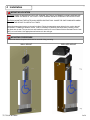
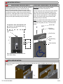
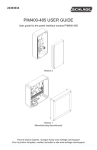
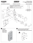
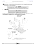
8310-836T (hardwired) or 8310-836TW (wireless) USER’S GUIDE Low Profile Push Plates 1 Description The 8310-836 is a 36 inch tall by 6 inch wide automatic door activation switch. Pressing anywhere on the switch surface will activate a door-open cycle. It is designed to mount directly to any flat wall surface or to LCN’s 8310-866FLA bollard post. The faceplate is made of stainless steel for durability, and has concealed fasteners for aesthetics and to minimize vandalism. The 8310-836T includes a two conductor wire harness to allow hardwired connection to the door operator system. The 8310-836TW includes a wireless transmitter in the top end cap to allow wireless connection to the door operator system. See page 3 for additional wiring descriptions. Please note that the 8310-836TW wireless switch is intended for interior installations. When exterior wireless installations are necessary, please use the 8310-836T switch, the 8310-866FLA bollard post, and the 8310-844 9v transmitter kit. 2 Specifications Switch Sub Assembly Push Plate Assembly Contact Configuration SPST N.O. Base Material 6063 Aluminum Switching Voltage .1 to 50 VDC Face Plate 304 Stainless Steel Switching Capacity 1 Watt Switch Actuator Material Nylon 66 Switching Current .005 to 100 ma DC End cap Material UL94 ABS Operating Temperature -32F (-35C) to 212F (100C) Hardware Stainless Steel CAUTION: To be connected to a Class 2, power limited, power source only. 3 Precautions Shut off all power going to header before attempting any wiring procedures. Maintain a clean & safe environment when working in public areas. Constantly be aware of pedestrian traffic around the door area. Always stop pedestrian traffic through the doorway when performing tests that may result in unexpected reactions by the door. ESD (electrostatic discharge): Circuit boards are vulnerable to damage by electrostatic discharge. Before handling any board ensure you dissipate your body’s ESD charge. Always check placement of all wiring before powering up to ensure that moving door parts will not catch any wires and cause damage to equipment. Ensure compliance with all applicable safety standards and/or building codes (i.e. ANSI A156.10, 156.19) upon completion of installation. DO NOT attempt any internal repair of the components. All repairs and/or component replacements must be performed by LCN. Unauthorized disassembly or repair: 1. May jeopardize personal safety and may expose one to the risk of electrical shock. 2. May adversely affect the safe and reliable performance of the product resulting in a voided warranty. 75.5739.02 20130208 1 of 4 4 Installation 1 MOUNTING LOCATION CAUTION: Prior to mounting the plate, ensure the two (2) in-transit locking screws are removed from the back of the plate. These screws are not required for installation. CAUTION: Mounting the plate on an uneven surface will cause the switching mechanism to hold the circuit closed at all times. Determine appropriate location on the wall or bollard. Follow the appropriate steps below for the version that will be installed. If installing a hardwire version, it will be necessary to (following the steps below) install a junction box flush with the wall. The junction box and installation needs to be in accordance with the National Electric Code (NEC) or Local Codes. Use appropriate wall anchors for the wall type. 2 MOUNTING PROCEDURE Please note that the faceplate should not be removed during mounting. WALL MOUNT 75.5739.02 20130208 BOLLARD MOUNT 2 of 4 3 MOUNTING DETAILS 3a HARD WIRED VERSION (WALL) Install an appropriate junction box flush with the mounting surface approximately 3 inches centered below top edge of the plate assembly. Remove top screw caps, end cap screws and end cap. Make necessary electrical connections ensuring to keep excess wire(s) inside the junction box. Install appropriate anchor thru top mounting hole. To avoid activation issues, do not push excess wire(s) into the plate assembly during re-assembly. WIRELESS VERSION (WALL OR BOLLARD) CAUTION: Do not pull on the cable attached to the top end cap. Remove Top Screw Caps, End Cap Screws and End Cap. Allow Top End Cap assembly to hang by the cable during the following steps. Install appropriate anchor thru top mounting hole. To avoid activation issues, do not push excess wire(s) into the plate assembly during re-assembly. NOTE: To complete the wireless setup procedure or change the battery, review the respective wireless transmitter user guide (75.5315 - LCN 433 User’s Guide). Screw Caps Route cable to flush mounted junction box. Ensure to use appropriate cable to activation input device. Top End Cap Screws Top Mounting Hole Top End Cap ss Wirele itter m s Tran Cable Top Mounting Hole 3” Junction Box Plate Assembly Plate assembly and end cap removed to show cable routing. 3b BOLLARD MOUNTING Hold the nylon spacer over the center mounting hole and attaching the switch to bollard using one 10-24 x .75 mounting screw. 75.5739.02 20130208 3 of 4 4 Installation continued 3 BOTTOM PLATE ASSEMBLY AND ALIGNMENT (WALL OR BOLLARD) To expose the bottom mounting hole, slide the front plate upwards a few inches. Insert one of the top end cap screws in the threaded hole on the bottom of the base plate to hold the front plate up. Plate Assembly Top End Cap Screw Bottom Mounting Hole With the bottom mounting hole now exposed, plumb the plate assembly and install the bottom mounting screw. r emove top end cap screw from base while supporting the front plate. Slide the front plate back down. r eplace top end cap with the provided screws and insert push-in plastic screw caps. 5 Cleaning The push plates are constructed with durable stainless steel and painted with scuff-resistant coatings. To clean the plates, use only a damp, non-abrasive cloth. r egular cleaning with harsh solvents or abrasive materials may cause deterioration of the paint coating. Ensure the user is aware of this procedure. 6 Company Contact ANSI / AAADM Compliance AAADM American Association of Automatic Door Manufactures Upon completion of the installation or service work, at a minimum, perform a daily safety check in accordance with the minimum inspection guidelines provided by AAADM. Provide each equipment owner with an owner’s manual that includes a daily safety checklist and contains, at a minimum, the information recommended by AAADM. Offer an information session with the equipment owner explaining how to perform daily inspections and point out the location of power/operation switches to disable the equipment if a compliance issue is noted. The equipment should be inspected annually in accordance with the minimum inspection guidelines. A safety check that includes, at a minimum, the items listed on the safety information label must be performed during each service call. If you are not an AAADM certified inspector, BEA strongly recommends you have an AAADM certified inspector perform an AAADM inspection and place a valid inspection sticker below the safety information label prior to putting the equipment into operation. 7 Company Contact Do not leave problems unresolved. If a satisfactory solution cannot be achieved after troubleshooting a problem, please contact LCN at 1-877-671-7011. If you must wait for the following workday to call LCN, leave the door inoperable until solution. For more information, visit www.allegion.com/us. 75.5739.02 20130208 4 of 4