1
1
Communications
Methods
2
CompoWay/F Communications Procedures
Digital Temperature Controllers
3
Communications
Data for CompoWay/F
4
Communications Manual
E5@C
Modbus Communications Procedure
5
Communications
Data for Modbus
6
Programless
Communications
7
Component
Communications
A
Appendices
I
Index
H175-E1-08
Preface
Preface
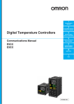
This Communications Manual describes the communications capabilities supported by the E5@C Digital Controllers.
Read and understand this manual before using communications with the E5@C Digital Controllers and
be sure you are performing communications correctly.
Keep this manual in a safe location where it will be available when needed.
© OMRON, 2011
All rights reserved. No part of this publication may be reproduced, stored in a retrieval system or transmitted, in any form,
or by any means, mechanical, electronic, photocopying, recording, or otherwise, without the prior written permission of
OMRON.
No patent liability is assumed with respect to the use of the information contained herein. Moreover, because OMRON is
constantly striving to improve its high-quality products, the information contained in this manual is subject to change
without notice. Every precaution has been taken in the preparation of this manual. Nevertheless, OMRON assumes no
responsibility for errors or omissions. Neither is any liability assumed for damages resulting from the use of the information
contained in this publication.
E5@C Digital Temperature Controllers Communications Manual (H175)
1
Terms and Conditions Agreement
Terms and Conditions Agreement
Warranty, Limitations of Liability
Warranties
z Exclusive Warranty
Omron’s exclusive warranty is that the Products will be free from defects in materials and
workmanship for a period of twelve months from the date of sale by Omron (or such other period
expressed in writing by Omron). Omron disclaims all other warranties, express or implied.
z Limitations
OMRON MAKES NO WARRANTY OR REPRESENTATION, EXPRESS OR IMPLIED, ABOUT
NON-INFRINGEMENT, MERCHANTABILITY OR FITNESS FOR A PARTICULAR PURPOSE OF
THE PRODUCTS. BUYER ACKNOWLEDGES THAT IT ALONE HAS DETERMINED THAT THE
PRODUCTS WILL SUITABLY MEET THE REQUIREMENTS OF THEIR INTENDED USE.
Omron further disclaims all warranties and responsibility of any type for claims or expenses based
on infringement by the Products or otherwise of any intellectual property right.
z Buyer Remedy
Omron’s sole obligation hereunder shall be, at Omron’s election, to (i) replace (in the form originally
shipped with Buyer responsible for labor charges for removal or replacement thereof) the
non-complying Product, (ii) repair the non-complying Product, or (iii) repay or credit Buyer an
amount equal to the purchase price of the non-complying Product; provided that in no event shall
Omron be responsible for warranty, repair, indemnity or any other claims or expenses regarding the
Products unless Omron’s analysis confirms that the Products were properly handled, stored,
installed and maintained and not subject to contamination, abuse, misuse or inappropriate
modification. Return of any Products by Buyer must be approved in writing by Omron before
shipment. Omron Companies shall not be liable for the suitability or unsuitability or the results from
the use of Products in combination with any electrical or electronic components, circuits, system
assemblies or any other materials or substances or environments. Any advice, recommendations or
information given orally or in writing, are not to be construed as an amendment or addition to the
above warranty.
See http://www.omron.com/global/ or contact your Omron representative for published information.
Limitation on Liability; Etc
OMRON COMPANIES SHALL NOT BE LIABLE FOR SPECIAL, INDIRECT, INCIDENTAL, OR CONSEQUENTIAL DAMAGES, LOSS OF PROFITS OR PRODUCTION OR COMMERCIAL LOSS IN ANY
WAY CONNECTED WITH THE PRODUCTS, WHETHER SUCH CLAIM IS BASED IN CONTRACT,
WARRANTY, NEGLIGENCE OR STRICT LIABILITY.
Further, in no event shall liability of Omron Companies exceed the individual price of the Product on
which liability is asserted.
2
E5@C Digital Temperature Controllers Communications Manual (H175)
Terms and Conditions Agreement
Application Considerations
Suitability of Use
Omron Companies shall not be responsible for conformity with any standards, codes or regulations
which apply to the combination of the Product in the Buyer’s application or use of the Product. At
Buyer’s request, Omron will provide applicable third party certification documents identifying ratings
and limitations of use which apply to the Product. This information by itself is not sufficient for a complete determination of the suitability of the Product in combination with the end product, machine, system, or other application or use. Buyer shall be solely responsible for determining appropriateness of
the particular Product with respect to Buyer’s application, product or system. Buyer shall take application responsibility in all cases.
NEVER USE THE PRODUCT FOR AN APPLICATION INVOLVING SERIOUS RISK TO LIFE OR
PROPERTY WITHOUT ENSURING THAT THE SYSTEM AS A WHOLE HAS BEEN DESIGNED TO
ADDRESS THE RISKS, AND THAT THE OMRON PRODUCT(S) IS PROPERLY RATED AND
INSTALLED FOR THE INTENDED USE WITHIN THE OVERALL EQUIPMENT OR SYSTEM.
Programmable Products
Omron Companies shall not be responsible for the user’s programming of a programmable Product, or
any consequence thereof.
Disclaimers
Performance Data
Data presented in Omron Company websites, catalogs and other materials is provided as a guide for
the user in determining suitability and does not constitute a warranty. It may represent the result of
Omron’s test conditions, and the user must correlate it to actual application requirements. Actual performance is subject to the Omron’s Warranty and Limitations of Liability.
Change in Specifications
Product specifications and accessories may be changed at any time based on improvements and other
reasons. It is our practice to change part numbers when published ratings or features are changed, or
when significant construction changes are made. However, some specifications of the Product may be
changed without any notice. When in doubt, special part numbers may be assigned to fix or establish
key specifications for your application. Please consult with your Omron’s representative at any time to
confirm actual specifications of purchased Product.
Errors and Omissions
Information presented by Omron Companies has been checked and is believed to be accurate; however, no responsibility is assumed for clerical, typographical or proofreading errors or omissions.
E5@C Digital Temperature Controllers Communications Manual (H175)
3
Safety Precautions
Safety Precautions
Definition of Precautionary Information
The following notation is used in this manual to provide precautions required to ensure safe usage of
the E5@C Digital Controllers.
The safety precautions that are provided are extremely important to safety. Always read and heed the
information provided in all safety precautions.
The following notation is used.
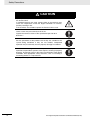
CAUTION
Indicates a potentially hazardous situation which, if not
avoided, may result in minor or moderate injury or in property damage.
Symbols
Symbol
Meaning
• General Caution
Indicates non-specific general cautions, warnings, and dangers.
Caution
• Electrical Shock Caution
Indicates possibility of electric shock under specific conditions.
• General Prohibition
Indicates non-specific general prohibitions.
Prohibition
• Disassembly Prohibition
Indicates prohibitions when there is a possibility of injury, such as from
electric shock, as the result of disassembly.
Mandatory
Caution
4
• General Caution
Indicates non-specific general cautions, warnings, and dangers.
E5@C Digital Temperature Controllers Communications Manual (H175)
Safety Precautions
z Safety Precautions
CAUTION
Minor injury due to electric shock may occasionally occur.
Do not touch the terminals while power is being supplied.
Electric shock, fire, or malfunction may occasionally occur.
Do not allow metal objects, conductors, cuttings from installation
work, or moisture to enter the Digital Controller or a Setup Tool port.
Attach the cover to the front-panel Setup Tool port whenever you are
not using it to prevent foreign objects from entering the port.
Minor injury from explosion may occasionally occur.
Do not use the product where subject to flammable or explosive gas.
Fire may occasionally occur.
Do not allow dirt or other foreign objects to enter a Setup Tool port,
or between the pins on the connectors on the Setup Tool cable.
Minor electric shock, fire, or malfunction may occasionally occur.
Never disassemble, modify, or repair the product or touch any of the
internal parts.
CAUTION - Risk of Fire and Electric Shock
(a) This product is UL listed as Open Type Process Control
Equipment. It must be mounted in an enclosure that does not
allow fire to escape externally.
(b) More than one disconnect switch may be required to
de-energize the equipment before servicing.
(c) Signal inputs are SELV, limited energy.*1
(d) Caution: To reduce the risk of fire or electric shock, do not
interconnect the outputs of different Class 2 circuits.*2
If the output relays are used past their life expectancy, contact fusing
or burning may occasionally occur.
Always consider the application conditions and use the output relays
within their rated load and electrical life expectancy. The life
expectancy of output relays varies considerably with the output load
and switching conditions.
*1
*2
An SELV (separated extra-low voltage) system is one with a power supply that has double or reinforced
insulation between the primary and the secondary circuits and has an output voltage of 30 V r.m.s. max.
and 42.4 V peak max. or 60 VDC max.
A class 2 circuit is one tested and certified by UL as having the current and voltage of the secondary output restricted to specific levels.
E5@C Digital Temperature Controllers Communications Manual (H175)
5
Safety Precautions
CAUTION
If you replace only the Main Unit of the E5DC, check the condition of
the Terminal Unit.
If corroded terminals are used, contact failure in the terminals may
cause the temperature inside the Digital Controller to increase,
possibly resulting in fire.
If the terminals are corroded, replace the Terminal Unit as well.
Loose screws may occasionally result in fire.
Tighten the terminal screws to the specified torque of 0.43 to
0.58 N·m.*
Set the parameters of the product so that they are suitable for the
system being controlled. If they are not suitable, unexpected
operation may occasionally result in property damage or accidents.
A malfunction in the Digital Controller may occasionally make control
operations impossible or prevent alarm outputs, resulting in property
damage. To maintain safety in the event of malfunction of the Digital
Controller, take appropriate safety measures, such as installing a
monitoring device on a separate line.
* The specified torque is 0.5 N·m for the E5CC-U.
6
E5@C Digital Temperature Controllers Communications Manual (H175)
Precautions for Safe Use
Precautions for Safe Use
Be sure to observe the following precautions to prevent operation failure, malfunction, or adverse
affects on the performance and functions of the product. Not doing so may occasionally result in unexpected events. Use the product within specifications.
• This product is designed for indoor use only. Do not use or store the Digital Temperature Controller in
any of the following places.
Places directly subject to heat radiated from heating equipment.
Places subject to splashing liquid or oil atmosphere.
Places subject to direct sunlight.
Places subject to dust or corrosive gas (in particular, sulfide gas and ammonia gas).
Places subject to intense temperature change.
Places subject to icing and condensation.
Places subject to vibration and large shocks.
• Use and store the Digital Controller within the rated ambient temperature and humidity.
Gang-mounting two or more Digital Controllers, or mounting Digital Controllers above each other may
cause heat to build up inside the Digital Controllers, which will shorten their service life. In such a
case, use forced cooling by fans or other means of air ventilation to cool down the Digital Controllers.
• To allow heat to escape, do not block the area around the product. Do not block the ventilation holes
on the product.
• Be sure to wire properly with the correct signal name and polarity of terminals.
• Use the specified size of crimped terminals (M3, width of 5.8 mm or less) to wire the E5CC, E5EC,
E5AC, or E5DC.
To connect bare wires to the terminal block of the E5CC, E5EC, E5AC, or E5DC, use copper braided
or solid wires with a gauge of AWG24 to AWG18 (equal to a cross-sectional area of 0.205 to 0.823
mm2). (The stripping length is 6 to 8 mm.) Up to two wires of the same size and type, or two crimped
terminals can be inserted into a single terminal.
Use the specified size of crimped terminals (M3, width of 5.8 mm or less) to wire the E5GC.*
To connect bare wires to the terminal block of the E5GC, use copper braided or solid wires with a
gauge of AWG24 to AWG18 (equal to a cross-sectional area of 0.205 to 0.823 mm2). (The stripping
length for Digital Temperature Controllers with screw terminal blocks is 6 to 8 mm. The stripping
length for Digital Temperature Controllers with screwless clamp terminal blocks is 8 to 12 mm.)
Up to two wires of the same size and type, or two crimped terminals can be inserted into a single
terminal. When connecting two wires into one terminal of a Digital Temperature Controller with a
screwless clamp terminal block, use ferrules with a diameter of 0.8 to 1.4 mm and an exposed
conductor length of 8 to 12 mm that two wires are crimped for a ferrule.*
* The Digital Temperature Controller with screwless clamp terminals underwent UL testing with one
braided wire connected.
• Do not wire the terminals that are not used.
• To avoid inductive noise, keep the wiring for the Digital Controller's terminal block away from power
cables that carry high voltages or large currents. Also, do not wire power lines together with or
parallel to Digital Controller wiring. Using shielded cables and using separate conduits or ducts are
recommended.
Attach a surge suppressor or noise filter to peripheral devices that generate noise (in particular,
motors, transformers, solenoids, magnetic coils or other equipment that have an inductance
component).
When a noise filter is used at the power supply, first check the voltage or current, and attach the noise
filter as close as possible to the Digital Controller.
E5@C Digital Temperature Controllers Communications Manual (H175)
7
Precautions for Safe Use
•
•
•
•
•
•
•
•
•
•
•
•
•
•
•
•
Allow as much space as possible between the Digital Controller and devices that generate powerful
high frequencies (high-frequency welders, high-frequency sewing machines, etc.) or surge.
Use the Digital Temperature Controller within the rated load and power supply.
Make sure that the rated voltage is attained within 2 seconds of turning ON the power using a switch
or relay contact. If the voltage is applied gradually, the power may not be reset or output malfunctions
may occur.
Make sure that the Digital Controller has 30 minutes or more to warm up after turning ON the power
before starting actual control operations to ensure the correct temperature display.
When executing self-tuning, turn ON power for the load (e.g., heater) at the same time as or before
supplying power to the Digital Controller. If power is turned ON for the Digital Controller before turning
ON power for the load, self-tuning will not be performed properly and optimum control will not be
achieved.
A switch or circuit breaker must be provided close to the Digital Controller. The switch or circuit
breaker must be within easy reach of the operator, and must be marked as a disconnecting means for
the Digital Controller.
Wipe off any dirt from the Digital Controller with a soft dry cloth. Never use thinners, benzine, alcohol,
or any cleaners that contain these or other organic solvents. Deformation or discoloration may occur.
Design the system (e.g., control panel) considering the 2 seconds of delay in setting the Digital
Controller’s output after the power supply is turned ON.
The output will turn OFF when you move to the initial setting level. Take this into consideration when
performing control.
The number of non-volatile memory write operations is limited. Therefore, use RAM write mode when
frequently overwriting data, e.g., through communications.
Use suitable tools when taking the Digital Controller apart for disposal. Sharp parts inside the Digital
Controller may cause injury.
Always touch a grounded piece of metal before touching the Digital Temperature Controller to
discharge static electricity from your body.
For compliance with Lloyd’s standards, the E5CC, E5CC-U, E5EC, or E5AC must be installed under
the conditions that are specified in Shipping Standards in the E5@C Digital Temperature Controller
User’s Manual (Cat. No. H174).
For the Digital Temperature Controller with two Setup Tool ports (E5EC/E5AC/E5DC/E5GC), do not
connect cables to both ports at the same time.
The Digital Temperature Controller may be damaged or may malfunction.
Do not exceed the communications distance that is given in the specifications and use the specified
communications cable. Refer to the E5@C Digital Temperature Controllers User’s Manual (Cat. No.
H174) for the communications distance and cable specifications.
Do not turn the power supply to the Digital Controller ON or OFF while the USB-Serial Conversion
Cable is connected. The Digital Controller may malfunction.
Do not bend the communications cables past their natural bending radius. Do not pull on the
communications cables.
• For the E5DC, when you attach the Main Unit to the Terminal Unit, make sure that the hooks on the
Main Unit are securely inserted into the Terminal Unit.
• Install the DIN Track vertically to the ground.
• For the E5DC, always turn OFF the power supply before connecting the Main Unit to or disconnecting
the Main Unit from the Terminal Unit, and never touch nor apply shock to the terminals or electronic
components. When connecting or disconnecting the Main Unit, do not allow the electronic
components to touch the case.
• Observe the following precautions when you remove the terminal block or pulling out (draw out) the
interior of the E5GC.
• Always follow the instructions provided in the E5@C Digital Controllers User’s Manual (Cat. No.
H174).
8
E5@C Digital Temperature Controllers Communications Manual (H175)
Precautions for Safe Use
• Turn OFF the power supply before you start and never touch nor apply shock to the terminals or
electric components.
When you insert the interior body of the Digital Controller, do not allow the electronic components
to touch the case.
• Check for any corrosion on the terminals.
• When you insert the interior body into the rear case, confirm that the hooks on the top and bottom
are securely engaged with the case.
E5@C Digital Temperature Controllers Communications Manual (H175)
9
Trademarks
Trademarks
• MELSEC and GX-Works are trademarks of the Mitsubishi Electric Corporation.
• Keyence KV STUDIO is a registered trademark of Keyence Corporation.
Other company names and product names in this document are the trademarks or registered trademarks of their respective companies.
10
E5@C Digital Temperature Controllers Communications Manual (H175)
Versions
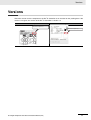
Versions
Check the version on the nameplate on the E5@C Controller or on the label on the packing box. If the
version is not given, the version of the E5@C Controller is version 1.0.
Product nameplate
Package label
The version is given here.
The version is given here.
E5@C Digital Temperature Controllers Communications Manual (H175)
11
Revision History
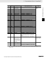
Revision History
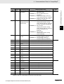
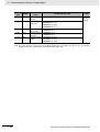
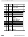
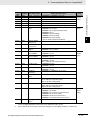
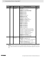
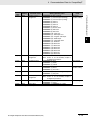
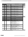
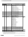
A manual revision code appears as a suffix to the catalog number on the front cover of the manual.
Cat. No.
H175-E1-08
Revision code
12
Revision code
01
02
03
Date
December 2011
January 2012
May 2012
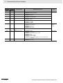
04
05
December 2012
March 2013
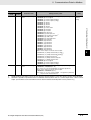
06
July 2013
07
December 2013
08
April 2014
Revised content
Original production
Page 9: Made correction in Precautions for Safe Use.
Added the following sections: Section 6 Programless
Communications and Section 7 Component Communications.
Page 10: Added trademark information.
Page 11: Added version information.
Page 13: Added functional upgrade information.
Pages 3-17 to 3-18: CompoWay/F variable area additions.
Corrected mistakes.
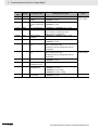
Added Digital Controllers with position-proportional control.
Page 13: Corrected maximum number of Controllers in four
locations and corrected last line.
Page 6-3: Corrected maximum number of Controllers in two
locations and corrected total number of words in middle of page.
Pages 6-7, 6-13, and 6-14: Corrected maximum number of
Controllers in table.
Page 7-2: Corrected maximum number of Controllers in figure.
Added E5DC Digital Controllers.
Page 6: Changed notes and changed caution mark.
Pages 7 and 9: Added precautions.
Page 11: Change figures.
Pages 13, 15, 6-1, and 7-1: Removed version indication.
Page 13: Changed sentence at bottom of page.
Page 1-4: Changed model designations and added figure.
Pages 3-15 and 5-8: Added "linear" in two places on each page.
Pages 3-20 and 5-14: Added LCT Cooling Output Minimum ON
Time.
Pages 6-1 and 7-1: Added version information.
Page 7-2: Changed model information and figure at bottom of
page.
Added Mitsubishi’s FX Series and Keyence’s KV Series to
programless communications.
Corrected mistakes.
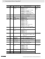
Made revisions accompanying addition of the E5GC.
Corrected mistakes.
E5@C Digital Temperature Controllers Communications Manual (H175)
Sections in This Manual
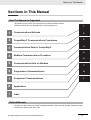
Sections in This Manual
How This Manual is Organized
Descriptions in this manual are separated by the communications method.
Read the sections that are applicable to the system being used.
1
1
Communications Methods
2
2
CompoWay/F Communications Procedures
3
3
Communications Data for CompoWay/F
4
5
4
Modbus Communications Procedure
6
5
Communications Data for Modbus
6
Programless Communications
A
7
Component Communications
I
A
Appendices
I
7
Index
Related Manuals
For details on the functions of the E5@C Digital Controllers, refer to the E5@C Digital Temperature Controllers User's Manual (Cat. No. H174).
E5@C Digital Temperature Controllers Communications Manual (H175)
13
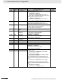
CONTENTS
Preface ....................................................................................................................... 1
Terms and Conditions Agreement........................................................................... 2
Warranty, Limitations of Liability ................................................................................................................. 2
Application Considerations ......................................................................................................................... 3
Disclaimers ................................................................................................................................................. 3
Safety Precautions .................................................................................................... 4
Definition of Precautionary Information ...................................................................................................... 4
Symbols ...................................................................................................................................................... 4
Precautions for Safe Use.......................................................................................... 7
Trademarks .............................................................................................................. 10
Versions ................................................................................................................... 11
Revision History ...................................................................................................... 12
Sections in This Manual ......................................................................................... 13
How This Manual is Organized ................................................................................................................. 13
Related Manuals ....................................................................................................................................... 13
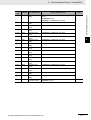
Section 1
1-1
Communications Methods
Overview of Communications Methods ................................................................................ 1-2
1-1-1
1-1-2
1-1-3
1-1-4
1-1-5
1-1-6
1-1-7
1-1-8
Section 2
2-1
CompoWay/F Communications Procedures
Data Format.............................................................................................................................. 2-2
2-1-1
2-1-2
2-1-3
2-1-4
2-1-5
2-2
PDU Structure............................................................................................................................. 2-6
Area Definitions........................................................................................................................... 2-6
Type Code (Variable Type) .......................................................................................................... 2-6
Addresses ................................................................................................................................... 2-7
Number of Elements ................................................................................................................... 2-7
List of Services (Main Request Codes and Sub-Request Codes) .............................................. 2-7
Detailed Description of the Services ..................................................................................... 2-8
2-3-1
2-3-2
2-3-3
14
Command Frame ........................................................................................................................ 2-2
BCC Calculation Example........................................................................................................... 2-3
Response Frame......................................................................................................................... 2-3
Communications Data................................................................................................................. 2-4
End Code Example ..................................................................................................................... 2-4
Structure of Command Text.................................................................................................... 2-6
2-2-1
2-2-2
2-2-3
2-2-4
2-2-5
2-2-6
2-3
Introduction ................................................................................................................................. 1-2
Communications Specifications .................................................................................................. 1-2
Transmission Procedure.............................................................................................................. 1-3
Interface ...................................................................................................................................... 1-3
Wiring.......................................................................................................................................... 1-4
Communications Parameters ...................................................................................................... 1-6
Communications Parameter Setup ............................................................................................. 1-7
Description of Communications Parameters ............................................................................... 1-8
Read Variable Area ..................................................................................................................... 2-8
Write Variable Area ..................................................................................................................... 2-9
Composite Read from Variable Area......................................................................................... 2-10
E5@C Digital Temperature Controllers Communications Manual (H175)
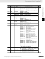
2-3-4
2-3-5
2-3-6
2-3-7
2-3-8
2-4
Composite Write to Variable Area............................................................................................. 2-12
Read Controller Attributes ........................................................................................................ 2-13
Read Controller Status ............................................................................................................. 2-14
Echoback Test .......................................................................................................................... 2-15
Operation Command ................................................................................................................ 2-16
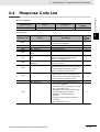
Response Code List .............................................................................................................. 2-21
Section 3
Communications Data for CompoWay/F
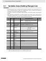
3-1
Variable Area (Setting Range) List ......................................................................................... 3-2
3-2
Status and Status 2 ............................................................................................................... 3-22
Section 4
4-1
Modbus Communications Procedure
Data Format.............................................................................................................................. 4-2
4-1-1
4-1-2
4-1-3
Command Frame ........................................................................................................................ 4-2
Response Frame ........................................................................................................................ 4-4
Error Codes ................................................................................................................................ 4-5
4-2
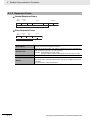
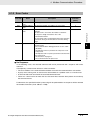
Function List ............................................................................................................................ 4-6
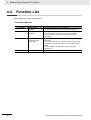
4-3
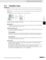
Variable Area ............................................................................................................................ 4-7
4-4
Detailed Description of the Functions ................................................................................... 4-8
4-4-1
4-4-2
4-4-3
4-4-4
Section 5
Variable Read, Multiple............................................................................................................... 4-8
Variable Write, Multiple ............................................................................................................. 4-10
Variable Write, Single/Operation Command ............................................................................. 4-12
Echoback Test .......................................................................................................................... 4-15
Communications Data for Modbus
5-1
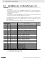
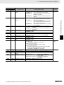
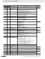
Variable Area (Setting Range) List ......................................................................................... 5-2
5-2
Status...................................................................................................................................... 5-17
Section 6
6-1
Programless Communications
Programless Communications............................................................................................... 6-3
6-1-1
6-1-2
6-1-3
6-1-4
6-1-5
6-2
E5@C Setup.............................................................................................................................. 6-6
6-2-1
6-2-2
6-2-3
6-2-4
6-2-5
6-2-6
6-2-7
6-2-8
6-2-9
6-2-10
6-2-11
6-3
Introduction ................................................................................................................................. 6-3
Features...................................................................................................................................... 6-3
Operation for Programless Communications .............................................................................. 6-4
Timing of Turning Power ON and OFF........................................................................................ 6-4
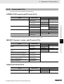
Connectable PLCs...................................................................................................................... 6-5
Protocol Setting .......................................................................................................................... 6-6
Communications Unit No. and Communications Baud Rate ...................................................... 6-7
Send Data Wait Time.................................................................................................................. 6-7
Highest Communications Unit No. .............................................................................................. 6-7
Areas and First Address of Linked Data ..................................................................................... 6-8
Receive Data Wait Time ........................................................................................................... 6-10
Communications Node Number................................................................................................ 6-10
Upload Settings and Download Settings .................................................................................. 6-11
Copying Parameter Settings ..................................................................................................... 6-13
Communications Writing........................................................................................................... 6-15
Communications Monitor Parameter ........................................................................................ 6-16
Controlling Programless Communications......................................................................... 6-17
6-3-1
6-3-2
Controlling Programless Communications with the Request Flag............................................ 6-17
Response Flag.......................................................................................................................... 6-18
E5@C Digital Temperature Controllers Communications Manual (H175)
15
6-3-3
6-3-4
6-3-5
6-3-6
6-3-7
6-4
Connecting to CP-series PLCs............................................................................................. 6-21
6-4-1
6-4-2
6-4-3
6-4-4
6-4-5
6-5
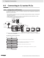
Configuration and Procedure .................................................................................................... 6-49
Wiring........................................................................................................................................ 6-50
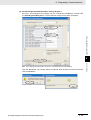
PLC Setup................................................................................................................................. 6-50
E5@C Controller Setup ............................................................................................................. 6-55
Checking Operation .................................................................................................................. 6-55
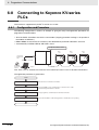
Connecting to Keyence KV-series PLCs ............................................................................. 6-56
6-8-1
6-8-2
6-8-3
6-8-4
6-8-5
Section 7
7-1
Configuration and Procedure .................................................................................................... 6-37
Wiring........................................................................................................................................ 6-38
PLC Setup................................................................................................................................. 6-38
E5@C Controller Setup ............................................................................................................. 6-43
Checking Operation .................................................................................................................. 6-44
Connecting to MELSEC-FX-series PLCs ............................................................................. 6-49
6-7-1
6-7-2
6-7-3
6-7-4
6-7-5
6-8
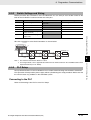
Configuration and Procedure .................................................................................................... 6-32
Switch Settings and Wiring ....................................................................................................... 6-33
PLC Setup................................................................................................................................. 6-33
E5@C Controller Setup ............................................................................................................. 6-36
Checking Operation .................................................................................................................. 6-36
Connecting to MELSEC Q-series PLCs ............................................................................... 6-37
6-6-1
6-6-2
6-6-3
6-6-4
6-6-5
6-7
Configuration and Procedure .................................................................................................... 6-21
Switch Settings and Wiring ....................................................................................................... 6-22
PLC Setup................................................................................................................................. 6-22
E5@C Controller Setup ............................................................................................................. 6-25
Checking Operation .................................................................................................................. 6-27
Connecting to CJ-series PLCs ............................................................................................. 6-32
6-5-1
6-5-2
6-5-3
6-5-4
6-5-5
6-6
Range of Operation for Programless Communications............................................................. 6-19
Operation Command Codes ..................................................................................................... 6-19
Confirming Operation of Programless Communications ........................................................... 6-19
Write Mode................................................................................................................................ 6-20
Troubleshooting......................................................................................................................... 6-20
Configuration and Procedure .................................................................................................... 6-56
Wiring........................................................................................................................................ 6-57
PLC Setup................................................................................................................................. 6-57
E5@C Controller Setup ............................................................................................................. 6-58
Checking Operation .................................................................................................................. 6-58
Component Communications
Component Communications................................................................................................. 7-2
7-1-1
7-1-2
7-1-3
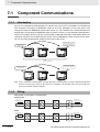
Introduction ................................................................................................................................. 7-2
Wiring.......................................................................................................................................... 7-2
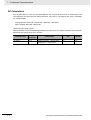
E5@C Setup................................................................................................................................ 7-3
7-2
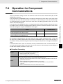
Operation for Component Communications ......................................................................... 7-5
7-3
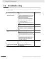
Troubleshooting....................................................................................................................... 7-6
Section A
Appendices
A-1 ASCII List..................................................................................................................................A-2
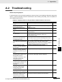
A-2 Troubleshooting.......................................................................................................................A-3
Index
16
E5@C Digital Temperature Controllers Communications Manual (H175)
1
Communications Methods
This section briefly describes the supported communications methods and how to wire
equipment. Refer to this section when setting up equipment.
1-1 Overview of Communications Methods . . . . . . . . . . . . . . . . . . . . . . . . . . . .
1-1-1 Introduction . . . . . . . . . . . . . . . . . . . . . . . . . . . . . . . . . . . . . . . . . . . . .
1-1-2 Communications Specifications . . . . . . . . . . . . . . . . . . . . . . . . . . . . . .
1-1-3 Transmission Procedure . . . . . . . . . . . . . . . . . . . . . . . . . . . . . . . . . . .
1-1-4 Interface . . . . . . . . . . . . . . . . . . . . . . . . . . . . . . . . . . . . . . . . . . . . . . . .
1-1-5 Wiring . . . . . . . . . . . . . . . . . . . . . . . . . . . . . . . . . . . . . . . . . . . . . . . . . .
1-1-6 Communications Parameters . . . . . . . . . . . . . . . . . . . . . . . . . . . . . . . .
1-1-7 Communications Parameter Setup . . . . . . . . . . . . . . . . . . . . . . . . . . .
1-1-8 Description of Communications Parameters . . . . . . . . . . . . . . . . . . . .
E5@C Digital Temperature Controllers Communications Manual (H175)
1-2
1-2
1-2
1-3
1-3
1-4
1-6
1-7
1-8
1-1
1 Communications Methods
1-1
Overview of Communications
Methods
1-1-1
Introduction
The program for the communications functions is created on the host (personal computer, PLC, or other
type of communications master), and the E5@C's parameters are monitored or set from the host.
Therefore, the description provided here is from the viewpoint of the host.
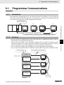
CompoWay/F is OMRON's standard communications format for general serial communications. This
format uses a standard frame format as well as the well-established FINS* commands used for
OMRON's PLCs. Therefore, it can simplify communications between components and the host.
*
FINS (Factory Interface Network service)
The FINS protocol provides message communications between controllers in OMRON FA networks.
Modbus is a standard communications control method that conforms to the Modicon Company's
RTU-mode Modbus Protocol (PI-MBUS-300 Revision J). Modbus is a registered trademark of
Schneider Electric.
It supports functions equivalent to the CompoWay/F Read Variable Area, Write Variable Area, Operation Command, and Echoback Test functions.
The E5@C supports the following communications functions.
• Reading/writing of parameters
• Operation instructions
• Selection of setup levels
Communications are subject to the following condition:
• Parameters can be written only when the Communications Writing parameter is set to ON (enabled).
1-1-2
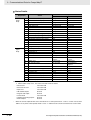
Communications Specifications
Transmission line connection
Communications method
Synchronization method
Communications baud rate *
Communications code
Communications data length *
Communications stop bits *
RS-485: Multidrop
RS-485 (2-wire, half-duplex)
Start-stop synchronization
9,600, 19,200, 38,400 or 57,600 bps
ASCII
7 or 8 bits
1 or 2 bits
Vertical parity (none, even, or odd) *
BCC (Block Check Character) with CompoWay/F communications
Error detection
CRC-16 (Cyclic Redundancy Check 16) with Modbus
communications
Flow control
None
Interface
RS-485
Retry function
None
Communications buffer
217 bytes
Send data wait time
0 to 99 ms, default time: 20 ms
*
Communications baud rate, data length, stop bits and vertical parity can each be set independently in the
communications setting level. Highlighted values indicate default settings.
1-2
E5@C Digital Temperature Controllers Communications Manual (H175)
1 Communications Methods
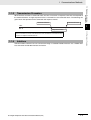
Transmission Procedure
When the host transmits a command frame, the E5@C transmits a response frame that corresponds to
the command frame. A single response frame is returned for each command frame. The following diagram shows the operation of the command and response frames.
Command frame
1-1 Overview of Communications Methods
1-1-3
Command frame
Host
1
E5@C
Allow a wait time of at least 2 ms before the next command is sent after the host
receives a response from the E5@C.
1-1-4
Interface
Communications with the host are carried out through a standard RS-485 interface. Use a K3SC Interface Converter for RS-485 interface conversion.
E5@C Digital Temperature Controllers Communications Manual (H175)
1-3
1-1-3 Transmission Procedure
Response frame
1 Communications Methods
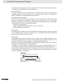
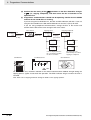
1-1-5
Wiring
z RS-485
• The RS-485 connection can be either one-to-one or one-to-N. Up to 32 units including the host
can be connected in a one-to-N system.
• The total cable length is 500 m max.
• Use a shielded twisted-pair cable with a wire gauge of AWG24 to AWG18 (cross-sectional area of
0.205 to 0.823 mm2).
E5CC/EC/AC
Communications
transceiver
Host
RS-485
E5CC/EC/AC
RS-485
Abbreviation
FG
TX
Abbreviation
−
Pin
14
+
13
B (+)
A (−)
RX
SG
6.8 V
A < B: "1" Mark
A > B: "0" Space
Shield
Terminator
120 Ω
(1/2 W)
E5CC/EC/AC
End node
RS-485
Pin
Specify both ends of the transmission path including the host
as the end node (that is, connect terminators to both ends).
Use a terminating resistance of at least 54 Ω.
1-4
Shield
Abbreviation
14
A (−)
13
B (+)
Use a 120 Ω (1/2 W)
terminator.
E5@C Digital Temperature Controllers Communications Manual (H175)
1 Communications Methods
1-1 Overview of Communications Methods
E5DC
Communications
transceiver
Host
RS-485
E5DC
RS-485
Abbreviation
FG
TX
Pin
4
Abbreviation
−
+
3
B (+)
1
A (−)
RX
1-1-5 Wiring
SG
6.8 V
Shield
A < B: "1" Mark
A > B: "0" Space
Terminator
120 Ω
(1/2 W)
Specify both ends of the transmission path including the host
as the end node (that is, connect terminators to both ends).
Use a terminating resistance of at least 54 Ω.
Shield
E5DC
End node
RS-485
Pin
Abbreviation
4
A (−)
3
B (+)
Use a 120 Ω (1/2 W) terminator.
E5GC
Communications transceiver
Host
RS-485
Abbreviation
E5GC
RS-485
FG
Pin
Abbreviation
−
8
A(-)
+
7
B(+)
TX
RX
SG
6.8V
A < B: "1" Mark
Shield
120 Ω (1/2 W) E5GC
terminating
End node
resistance
RS-485
A > B: “0” Space
Specify both ends of the transmission path
including the host as the end node (that is,
connect terminators to both ends). Use a
terminating resistance of at least 54 Ω.
Shield
Pin
Abbreviation
8
A(-)
7
B(+)
Use a 120 Ω (1/2 W) terminator.
Match the communications specifications of the E5@C and the host. When using a 1:N connection,
set the same communications specifications in all of the Units. Each Communications Unit must
have a unique unit number.
This section explains how to set the E5@C's communications specifications. For details on the host,
refer to the user's manual provided with the host.
E5@C Digital Temperature Controllers Communications Manual (H175)
1-5
1 Communications Methods
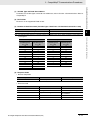
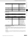
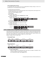
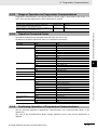
1-1-6
Communications Parameters
The E5@C's communications specifications are set in the communications setting level. These parameters are set on the E5@C's front panel. The following table shows the communications parameters and
their setting ranges.
Item
Communications protocol
setting
Communications unit number
Communications baud rate
Communications data length *
Communications stop bits *
Communications parity
Send data wait time
Code
psel
u-no
bps
len
sbit
prty
sdwt
Settings
CompoWay/F /Modbus
cwf/mod
Set Values
0 to 99
9.6/19.2/38. 4/57.6 (kbit/s)
7/8 (bit)
1/2
None, Even, Odd
0 to 99
0, 1 to 99
9.6/19.2 /38.4/57.6 (kbit/s)
7/8 (bit)
1/2
none/eVen/odd
0 to 99 ms, default time: 20 ms
Highlighted values indicate default settings.
*
1-6
When the Protocol Setting parameter is set to Modbus, the communications data length must be 8 bits, and the
communications stop bits must be 1 bit by setting the communications parity to Even/Odd or it must be 2 bits
by setting the parity to None. These two parameters are not displayed on the Controller's display.
E5@C Digital Temperature Controllers Communications Manual (H175)
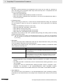
1 Communications Methods
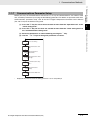
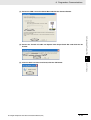
Before you carry out communications with the E5@C, set up the communications unit number, baud
rate, and other parameters by carrying out the following procedure. For details on operations other than
communications parameter setup, refer to the E5@C Digital Temperature Controllers User's Manual
(Cat. No. H174) for the devices being used.
1-1 Overview of Communications Methods
(1) Press the O Key for at least three seconds to move from the "operation level" to the
"initial setting level."
1
1-1-7
Communications Parameter Setup
(3) Select the parameters as shown below by pressing the M Key.
(4) Use the D or U Keys to change the parameter set values.
psel
Protocol Setting
cwf
M
u-no
1
Communications Unit
No.
M
bps
9.6
Communications
Baud Rate
M
len
7
Communications Data
Length *
M
sbit
2
Communications Stop
Bits *
M
prty
Communications
even Parity
M
sdwt
Send Data Wait Time
20
M
*
Displayed only when the Protocol Setting parameter is set to CompoWay/F.
E5@C Digital Temperature Controllers Communications Manual (H175)
1-7
1-1-7 Communications Parameter Setup
(2) Press the O Key for less than one second to move from the "initial setting level" to
the "communications setting level."
1 Communications Methods
1-1-8
Description of Communications Parameters
When communications parameter settings have been changed, the new settings must be enabled by
resetting the Controller.
• Protocol Setting (psel)
The communications protocol can be selected. Set CompoWay/F or Modbus.
• Communications Unit No. (u-no)
This parameter is for setting a unique unit number for each of the Digital Controllers. This unit number is set so that the host can identify the Digital Controller when communications are carried out
with the host. The unit number can be set to an integer value between 0 and 99. The default is “1.”
When two or more Digital Controllers are used, do not set the same unit number. Doing so will prevent normal operation.
• Communications Baud Rate (bps)
This parameter is for setting the baud rate for communications with the host. The communications
baud rate settings are as follows: 9.6 (9600 bps), 19.2 (19200 bps), 38.4 (38400 bps) or 57.6 (57600
bps)
• Communications Data Length (len)
This parameter is for setting the number of communications data bits. Set either “7 bits” or “8 bits.”
• Communications Stop Bits (sbit)
This parameter is for setting the number of communications stop bits. Set either “1” or “2.”
• Communications Parity (prty)
This parameter is for setting the communications parity. Set the parity to “none,” “even,” or “odd.”
• Send Data Wait Time (sdwt)
The send data wait time is the delay from when the Controller receives a command from the host
computer until it returns a response. If the response is returned too quickly, the host computer may
not be able to receive the response. Change the send data wait time as required. To increase the
response speed for communications, reduce the send data wait time. The send data wait time can
be set in 1-ms increments between 0 and 99 ms. The default is 20 ms.
1-8
E5@C Digital Temperature Controllers Communications Manual (H175)
CompoWay/F Communications
Procedures
2
Read this section if you are to communicate using the CompoWay/F format.
2-1 Data Format . . . . . . . . . . . . . . . . . . . . . . . . . . . . . . . . . . . . . . . . . . . . . . . . . . 2-2
2-1-1
2-1-2
2-1-3
2-1-4
2-1-5
Command Frame . . . . . . . . . . . . . . . . . . . . . . . . . . . . . . . . . . . . . . . . . . . . . . .
BCC Calculation Example . . . . . . . . . . . . . . . . . . . . . . . . . . . . . . . . . . . . . . . .
Response Frame . . . . . . . . . . . . . . . . . . . . . . . . . . . . . . . . . . . . . . . . . . . . . . .
Communications Data . . . . . . . . . . . . . . . . . . . . . . . . . . . . . . . . . . . . . . . . . . . .
End Code Example . . . . . . . . . . . . . . . . . . . . . . . . . . . . . . . . . . . . . . . . . . . . . .
2-2
2-3
2-3
2-4
2-4
2-2 Structure of Command Text . . . . . . . . . . . . . . . . . . . . . . . . . . . . . . . . . . . . . 2-6
2-2-1
2-2-2
2-2-3
2-2-4
2-2-5
2-2-6
PDU Structure . . . . . . . . . . . . . . . . . . . . . . . . . . . . . . . . . . . . . . . . . . . . . . . . . .
Area Definitions . . . . . . . . . . . . . . . . . . . . . . . . . . . . . . . . . . . . . . . . . . . . . . . .
Type Code (Variable Type) . . . . . . . . . . . . . . . . . . . . . . . . . . . . . . . . . . . . . . . .
Addresses . . . . . . . . . . . . . . . . . . . . . . . . . . . . . . . . . . . . . . . . . . . . . . . . . . . . .
Number of Elements . . . . . . . . . . . . . . . . . . . . . . . . . . . . . . . . . . . . . . . . . . . . .
List of Services (Main Request Codes and Sub-Request Codes) . . . . . . . . . .
2-6
2-6
2-6
2-7
2-7
2-7
2-3 Detailed Description of the Services . . . . . . . . . . . . . . . . . . . . . . . . . . . . . . 2-8
2-3-1
2-3-2
2-3-3
2-3-4
2-3-5
2-3-6
2-3-7
2-3-8
Read Variable Area . . . . . . . . . . . . . . . . . . . . . . . . . . . . . . . . . . . . . . . . . . . . . . 2-8
Write Variable Area . . . . . . . . . . . . . . . . . . . . . . . . . . . . . . . . . . . . . . . . . . . . . . 2-9
Composite Read from Variable Area . . . . . . . . . . . . . . . . . . . . . . . . . . . . . . . 2-10
Composite Write to Variable Area . . . . . . . . . . . . . . . . . . . . . . . . . . . . . . . . . . 2-12
Read Controller Attributes . . . . . . . . . . . . . . . . . . . . . . . . . . . . . . . . . . . . . . . . 2-13
Read Controller Status . . . . . . . . . . . . . . . . . . . . . . . . . . . . . . . . . . . . . . . . . . 2-14
Echoback Test . . . . . . . . . . . . . . . . . . . . . . . . . . . . . . . . . . . . . . . . . . . . . . . . . 2-15
Operation Command . . . . . . . . . . . . . . . . . . . . . . . . . . . . . . . . . . . . . . . . . . . . 2-16
2-4 Response Code List . . . . . . . . . . . . . . . . . . . . . . . . . . . . . . . . . . . . . . . . . . . 2-21
E5@C Digital Temperature Controllers Communications Manual (H175)
2-1
2 CompoWay/F Communications Procedures
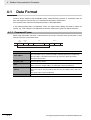
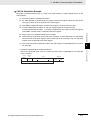
2-1
Data Format
Hexadecimal values are expressed by adding the prefix H' before the number, e.g., H'02. Numbers
shown without the H' prefix are ASCII characters.
The number underneath each item in a frame indicates the number of bytes.
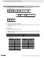
2-1-1
Command Frame
Text
Node number Sub-address SID
STX
1
0
0
2
2
Command text
BCC
0
ETX
1
1
1
BCC calculation range
STX
Node number
Sub-address
SID (Service ID)
Command text
ETX
BCC
2-2
This code (H'02) indicates the beginning of the communications frame
(text).
Always set this character in the first byte.
When STX is received again during reception, reception is carried out
again from the point where STX was received.
• This number specifies the transmission's destination.
• Specify the E5@C's communications unit number.
• A BCD value between 00 and 99 or an ASCII value of XX can be set.
• Specify “XX” for a broadcast transmission. No responses will be
returned for broadcast transmissions.
• No responses will be returned from node numbers other than the ones
in the above range.
Always set the sub-address to “00.”
Always set the service ID to “0.”
This is the command text area. For details, refer to 2-2 Structure of
Command Text.
This code (H'03) indicates the end of the text.
This is the Block Check Character.
The BCC result is found by calculating the exclusive OR of the bytes from
the node number up to ETX.
E5@C Digital Temperature Controllers Communications Manual (H175)
2 CompoWay/F Communications Procedures
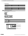
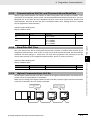
2-1-2
BCC Calculation Example
The BCC (Block Check Character) is determined by calculating the exclusive OR of the bytes from the
node number up to ETX. The 8-bit result is written to the BCC byte at the end of the frame.
Node number
02H
0 (30H) 0 (30H) 0 (30H) 0 (30H) 0 (30H) 0 (30H) 5 (35H) 0 (30H) 3 (33H)
Sub-address
Command text
ETX
BCC
03H
35H
2-1 Data Format
SID
STX
BCC = 30H+30H+30H+30H+30H+30H+35H+30H+33H+03H = 35H
2
The result of the calculation (35 hex) is written to the BCC byte.
The + symbols indicate XOR (exclusive OR) operations.
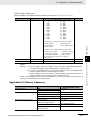
Response Frame
Node number Sub-address End code
STX
0
1
End code
00
2
11
12
13
Normal completion
FINS command error
Parity error
Framing error
Overrun error
BCC error
Format error
14
Sub-address error
16
18
ETX
2
Name
0F
10
0
2
Frame length error
BCC
Command text
1
Description
The command ended normally without error.
The specified FINS command could not be executed.
The FINS response code should indicate why the command
could not be executed.
The sum total of bits whose received data is “1” does not
match the set value of the "communications parity" bit.
Stop bit is “0.”
An attempt was made to transfer new data when the
reception data buffer was already full.
The calculated BCC value is different from the received BCC
value.
• The command text contains characters other than 0 to 9,
and A to F. This error does not apply to Echoback Tests.
(Refer to 2-3-7 Echoback Test for details.)
• There was no SID and command text. There was no
command text.
• “MRC/SRC” not included in command text.
• Illegal (unsupported) sub-address
• There was no sub-address, SID, and command text.
• Sub-address was less than two characters, and there was
no SID and command text
The received frame exceeds the specified (supported)
number of bytes.
1
Error detection
priority
None
8
2
1
3
5
7
6
4
• An end code is returned for each command frame received that was addressed to the local node.
• No response will be returned unless the frame contained all elements up to the ETX and BCC.
• “Error Detection Priority” indicates the priority when two or more errors occur simultaneously.
E5@C Digital Temperature Controllers Communications Manual (H175)
2-3
2-1-2 BCC Calculation Example
2-1-3
2 CompoWay/F Communications Procedures
2-1-4
Communications Data
Communications
format
CompoWay/F
2-1-5
Set (monitor)
Negative values
values
8-digit hexadecimal 2's complement
Decimal point
Decimal point is removed and the result is
converted to hexadecimal.
Example conversion: 105.0 → 1050 →
H'0000041A
End Code Example
The following examples show the end code when a command did not end normally.
Example 1) Illegal Sub-address, No SID, and No Command Text
• Command
Node number Sub-address
STX
0
A
BCC
ETX
• Response
Node number Sub-address
STX
0
A
BCC
End code
1
6
ETX
End code is “16” (sub-address error).
The sub-address error code is used because the sub-address error has a higher error detection
priority than the format error.
Example 2) No Command Text
• Command
Node number Sub-address SID
STX
0
0
0
BCC
ETX
• Response
Node number Sub-address
STX
0
0
BCC
End code
1
4
ETX
The end code is “14” (format error).
Example 3) No Node Number Provided
• Command
BCC
STX
ETX
The node number is lacking one character.
• Response
There is no response.
2-4
E5@C Digital Temperature Controllers Communications Manual (H175)
2 CompoWay/F Communications Procedures
Example 4) No Sub-address and Illegal BCC
• Command
Node number
ETX
2-1 Data Format
STX
BCC
Err
• Response
Node number Sub-address
STX
0
0
End code
1
3
BCC
ETX
2
The sub-address is “00” and the end code is “13” (BCC error).
2-1-5 End Code Example
E5@C Digital Temperature Controllers Communications Manual (H175)
2-5
2 CompoWay/F Communications Procedures
2-2
2-2-1
Structure of Command Text
PDU Structure
An MRC (Main Request Code) and SRC (Sub-Request Code) followed by the various required data is
transferred to the command text.
• Service Request PDU
MRC SRC
Data
The MRES (Main Response Code) and SRES (Sub-Response Code) are transferred to the
response frame following the above MRC/SRC. Data is then transferred following the MRES and
SRES.
• Service Response PDU (Normal Response)
Data
MRC SRC MRES SRES
If the specified command text could not be executed, the service response PDU will contain only the
MRC/SRC and MRES/SRES.
• Service Response PDU (Command Text Not Executed)
MRC SRC MRES SRES
MRES/SRES provides the response code. MRES/SRES are not output when processing ends in a
normal completion.
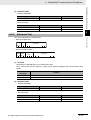
2-2-2
Area Definitions
Areas comprise only the variable area.
2-2-3
Type Code (Variable Type)
The following figure shows the variable area type code.
Variable type (1 byte)
MSB
LSB
0
Access size
11: Double word
10: Word
0
0
0
Area
0: Setup area 0
1: Setup area 1
Read/Write
0: Read only
1: Read/Write
The following table summarizes setup areas 0 and 1.
Area
Setup area 0
Setup area 1
Description
This area groups together the protect, manual control, operation, and adjustment
levels.
This area groups together the initial setting, communications setting, advanced
function setting, and calibration levels.
The type code depends on the parameter. Refer to 3-1 Variable Area (Setting Range) List for details.
2-6
E5@C Digital Temperature Controllers Communications Manual (H175)
2 CompoWay/F Communications Procedures
Variable type
Description
C0/80
R/O (read only) parameter for setup area 0.
C1/81
R/W parameter for setup area 0.
C3/83
R/W parameter for setup area 1.
Note: Setup area 1 has no read-only parameters, so there is no variable type "C2."
2-2-4
Addresses
2
Number of Elements
The number of elements is expressed in 2-byte hexadecimal. The range that can be specified for the
number of elements depends on the command. Refer to 2-3 Detailed Description of the Services for
details.
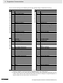
2-2-6
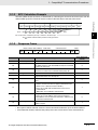
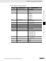
List of Services (Main Request Codes and Sub-Request Codes)
01
MRC
01
SRC
Name of service
Read Variable Area
01
01
02
04
Write Variable Area
Composite Read from Variable Area
01
13
Composite Write to Variable Area
05
03
Read Controller Attributes
06
08
30
01
01
05
Read Controller Status
Echoback Test
Operation Command
Processing
This service reads from the variable
area.
This service writes to the variable area.
This service reads from the variable area
in the order specified by the parameters.
This service writes to the variable area in
the order specified by the parameters.
This service reads the model number
and communications buffer size.
This service reads the operating status.
This service performs an echoback test.
This service performs operations such
as RUN/STOP, executing/stopping AT
(auto-tuning), and moving to Setup Area
1.
Note: No commands will be accepted and no responses will be returned when a memory error (RAM error) has
occurred or the Controller is initializing (until the Controller recognizes the process value after the power is
turned ON).
E5@C Digital Temperature Controllers Communications Manual (H175)
2-7
2-2-4 Addresses
An address is appended to each of the variable types. Express addresses in 2-byte hexadecimal and
append them for the specified access size. The address depends on the parameter. Refer to 3-1 Variable Area (Setting Range) List for details.
2-2-5
2-2 Structure of Command Text
The variable type is converted to 2-byte ASCII and loaded to the frame. The following table shows the
available variable types.
2 CompoWay/F Communications Procedures
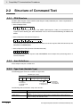
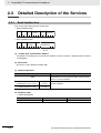
2-3
Detailed Description of the Services
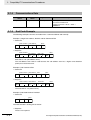
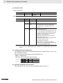
2-3-1
Read Variable Area
This service reads data from the variable area.
• Service Request PDU
MRC SRC
0
1
0
2
Variable
type
Read start
address
Bit
position
4
0 0
2
1
2
2
Number of
elements
4
• Service Request PDU
MRC SRC
0
1
2
(1)
0
1
2
Response
code
Read data (for number
of elements)
4
Number of elements
× 8 or 4
Variable Type and Read Start Address
For details on variable types and read start addresses, refer to Section 3 Communications Data for
CompoWay/F.
(2) Bit Position
Bit access is not supported. Fixed to “00.”
(3) Number of Elements
Number of elements
0000
Double word
(variable type C0, C1, or C3)
Word
(variable type 80, 81, or 83)
0001 to 0019
(1 to 25)
0001 to 0032
(1 to 50)
Processing
The read operation is not performed (read data is not
appended to the service response PDU), and processing
ends in a normal completion.
The read operation is performed and processing ends in a
normal completion.
(4) Response Code
• Normal Completion
Response code
0000
2-8
Name
Normal completion
Description
No errors were found.
E5@C Digital Temperature Controllers Communications Manual (H175)
2 CompoWay/F Communications Procedures
Response code
1001
1002
1101
Error name
Command too long
Command too short
Area type error
Start address out-of-range error
1103
Response too long
110B
1100
2203
Parameter error
Operation error
Cause
The command is too long.
The command is too short.
The variable type is wrong.
The read start address is out of
range.
The number of elements exceeds
the maximum.
Bit position is not “00.”
Non-volatile memory error
2-3 Detailed Description of the Services
• Error Occurred
2
2-3-2
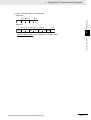
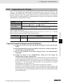
Write Variable Area
This service writes data to the variable area.
• Service Request PDU
MRC SRC
0
1
0
2
Variable
type
Start write
address
2
4
2
2
Bit
position
0
Number of
elements
Write Data (for number
of elements)
4
Number of elements
× 8 or 4
0
2
• Service Response PDU
MRC SRC
0
1
2
0
Response
code
2
2
4
(1) Variable Type and Write Start Address
For details on variable types and write start addresses, refer to Section 3 Communications Data for
CompoWay/F.
(2) Bit Position
Bit access is not supported. Fixed to “00.”
(3) Number of Elements
Number of elements
0000
Double word
(variable type C0, C1, or C3)
Word
(variable type 80, 81, or 83)
0001 to 0018
(1 to 24)
0001 to 0030
(1 to 48)
E5@C Digital Temperature Controllers Communications Manual (H175)
Processing
The write operation is not performed (do not append write
data to the service request PDU) and processing ends in a
normal completion.
The write operation is performed and processing ends in a
normal completion.
2-9
2-3-2 Write Variable Area
(5) Precautions
• Alarm Function
Even though alarms are not displayed on the Controller's display, they function normally in
communications.
2 CompoWay/F Communications Procedures
(4) Response Code
• Normal Completion
Response code
0000
Name
Normal completion
Description
No errors were found.
Error name
Command too short
Area type error
Start address out-of-range error
End address out-of-range error
Cause
The command is too short.
The variable type is wrong.
Write start address is out of range.
The write end address (write start address +
number of elements) exceeds the final address of
the variable area.
The number of data does not match the number of
elements.
• Bit position is not “00.”
• The write data is out of the setting range.
Variable type “C0” was written to.
• The Communications Writing parameter is set to
“OFF” (disabled).
• Attempted to write to a parameter in setup area
1 from setup area 0.
• Attempted to write to a protect parameter from
other than the protect level.
• AT (auto-tuning) was in progress. *
• Non-volatile memory error
• Error Occurred
Response code
1002
1101
1103
1104
Number of elements/data
mismatch
Parameter error
1003
1100
3003
Read-only error
Operation error
2203
* For details on AT (auto-tuning), refer to the E5@C Digital Temperature Controllers User's Manual (Cat. No.
H174).
(5) Precautions
• Alarm Function
Even though alarms are not displayed on the Controller's display, they function normally in
communications.
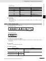
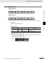
2-3-3
Composite Read from Variable Area
This service reads in order the contents of specified addresses in the variable area.
• Service Request PDU
MRC SRC Variable
type
0 1 0 4
2
2
2
Read
address
Bit
position
Variable
type
Read
address
Bit
position
4
0 0
2
2
4
0 0
2
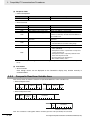
• Service Response PDU
MRC SRC
0
1
2
0
Response
code
Variable
type
Read data
4
2
Number of elements ×8 or 4
4
2
Variable
type
Read data
2
Number of elements ×8 or 4
Note: The read data is read together with the variable type in the order specified by the command.
2 - 10
E5@C Digital Temperature Controllers Communications Manual (H175)
2 CompoWay/F Communications Procedures
(2) Bit Position
Bit access is not supported. Fixed to “00.”
(3) Number of Read Data Items (Variable Type + Read Data + Bit Position Counted As 1 Item)
Composite Read
Composite Read
Double word
(variable type C0,
C1, or C3)
Word
(variable type 80,
81, or 83)
Double word
(variable type C0,
C1, or C3)
Word
(variable type 80,
81, or 83)
20
0
11
14
19
1
10
15
18
2
9
16
18
3
8
17
17
4
7
18
17
5
6
19
16
6
8
20
15
7
4
21
15
8
3
22
14
9
2
23
14
10
1
24
13
11
0
25
12
12
12
13
(4) Response Code
• Normal Completion
Response code
0000
Name
Normal completion
Description
No errors were found.
Error name
Command too short
Area type error
Response too long
Cause
The command is too short.
The variable type is wrong.
The number of elements exceeds
the maximum.
Bit position is not "00."
Non-volatile memory error
• Error Occurred
Response code
1002
1101
110B
1100
2203
Parameter error
Operation error
E5@C Digital Temperature Controllers Communications Manual (H175)
2 - 11
2
2-3-3 Composite Read from Variable Area
Read data length
Number of read data items
For double word (variable type C0, C1, or C3)
20 max.
For word (variable type 80, 81, or 83)
25 max.
Note: The following table gives the maximum number of read data items when double-word data and word data are
used together.
2-3 Detailed Description of the Services
(1) Variable Type and Read Start Address
For details on variable types and read start addresses, refer to Section 3 Communications Data for
CompoWay/F.
2 CompoWay/F Communications Procedures
2-3-4
Composite Write to Variable Area
This service writes in order the contents of specified addresses to a variable area.
• Service Request PDU
Write
address
MRC SRC Variable
type
0 1 1 3
2
2
2
4
Bit
position
Write data
0 0
2 Number of elements ×8 or 4
Variable
type
Write
address
2
4
Bit
Write data
position
0 0
2 Number of elements ×8 or 4
• Service Response PDU
Response
code
MRC SRC
0
1
2
1
3
2
4
(1) Variable Type and Write Start Address
For details on variable types and write start addresses, refer to Section 3 Communications Data for
CompoWay/F.
(2) Bit Position
Bit access is not supported. Fixed to “00.”
(3) Number of Write Data Items (Variable Type + Write Address + Bit Position + Write Data
Counted As 1 Item)
Write data length
Number of write data items
For double word (variable type C0, C1, or C3)
12 max.
For word (variable type 80, 81, or 83)
17 max.
Note: The following table gives the maximum number of write data items when double-word data and word data
are used together.
Composite Write
2 - 12
Composite Write
Double word
(variable type C0,
C1, or C3)
Word
(variable type 80,
81, or 83 )
Double word
(variable type C0,
C1, or C3)
Word
(variable type 80,
81, or 83)
12
0
5
10
12
1
4
11
11
2
3
12
10
3
3
13
9
4
2
14
9
5
1
15
8
6
0
16
7
7
0
17
6
8
6
9
E5@C Digital Temperature Controllers Communications Manual (H175)
2 CompoWay/F Communications Procedures
Response code
0000
Name
Normal completion
Description
No errors were found.
• Error Occurred
Response code
1002
1101
1100
3003
Error name
Command too short
Area type error
Parameter error
2203
* For details on AT (auto-tuning), refer to the E5@C Digital Temperature Controllers User's Manual (Cat. No.
H174).
2-3-5
Read Controller Attributes
This service reads the model number and communications buffer size.
• Service Request PDU
MRC SRC
0
5
0
2
3
2
• Service Response PDU
MRC SRC
0
5
2
(1)
0
Response
code
Model No.
4
10
3
2
Buffer size
0
0
D 9
4
Model Number
The model number is expressed in 10-byte ASCII.
Example: The model is given as shown below for the E5CC-RX2ASM-000
(relay output, 2 auxiliary outputs, and no options).
E 5 C C -
R X 2 A S
(2) Buffer Size
The communications buffer size is expressed in 2-byte hexadecimal, and read after being converted
to 4-byte ASCII.
Buffer size: 217 bytes (= H'00D9)
E5@C Digital Temperature Controllers Communications Manual (H175)
2 - 13
2
2-3-5 Read Controller Attributes
Read-only error
Operation error
Cause
The command is too short.
The variable type is wrong.
• Bit position is not “00.”
• The write data is out of the setting range.
Variable type “C0” was written to.
• The Communications Writing parameter is set to “OFF”
(disabled).
• Attempted to write to a parameter in setup area 1 from
setup area 0.
• Attempted to write to a protect parameter from other
than the protect level.
• AT (auto-tuning) was in progress. *
• Non-volatile memory error
2-3 Detailed Description of the Services
(4) Response Code
• Normal Completion
2 CompoWay/F Communications Procedures
(3) Response Code
• Normal Completion
Response code
0000
Name
Normal completion
Description
No errors were found.
Error name
Command too long
Operation error
Description
The command is too long.
Non-volatile memory error
• Error Occurred
Response code
1001
2203
2-3-6
Read Controller Status
This service reads the operating status and error status.
• Service Request PDU
MRC SRC
0
6
0
2
1
2
• Service Response PDU
MRC SRC
0
6
2
0
1
Response Operating Related
informacode
status
tion
2
4
2
2
(1) Operating Status
Operating status
00
01
Description
Control is being carried out (error has not occurred in setup area 0 and the Controller is
running).
Control is not being carried out (state other than above).
(2) Related Information
7
6
5
4
3
2
1
0
Bit position
0
Heater overcurrent (CT1)
Heater current hold (CT1)
AD converter error
Heater overcurrent (CT2)
Heater current hold (CT2)
Input error
Potentiometer input error
2 - 14
E5@C Digital Temperature Controllers Communications Manual (H175)
2 CompoWay/F Communications Procedures
2-3 Detailed Description of the Services
(3) Response Code
• Normal Completion
Response code
0000
Name
Normal completion
Description
No errors were found.
Error name
Command too long
Operation error
Description
The command is too long.
Non-volatile memory error
• Error Occurred
Response code
1001
2203
2
2-3-7
Echoback Test
2-3-7 Echoback Test
This service performs an echoback test.
• Service Request PDU
MRC SRC
0
8
0
2
Test data
1
2
0 to 200
• Service Response PDU
MRC SRC
0
8
2
0
Response
code
Test data
4
0 to 200
1
2
(1) Test Data
Set between 0 and 200 bytes of user-defined test data.
Set a value for the test data within the ranges shown below according to the communications data
length.
Communications
data length
8 bits
7 bits
Test Data
ASCII data: H'20 to H'7E or H'A1 to H'FE
ASCII data: H'20 to H'7E
(2) Response Code
• Normal Completion
Response code
0000
Name
Normal completion
Description
No errors were found.
Error name
Command too long
Operation error
Description
The command is too long.
Non-volatile memory error
• Error Occurred
Response code
1001
2203
E5@C Digital Temperature Controllers Communications Manual (H175)
2 - 15
2 CompoWay/F Communications Procedures
2-3-8
Operation Command
•
•
•
•
•
Communications Writing
AT Execute/Cancel
Software Reset
Auto/Manual Switch
Invert Direct/Reverse
Operation
•
•
•
•
•
RUN/STOP
Write Mode
Move to Setup Area 1
Parameter Initialization
Program Start
•
•
•
•
•
Multi-SP
Save RAM Data
Move to Protect Level
Alarm Latch Cancel
SP Mode
• Service Request PDU
MRC SRC
3
0
0
5
2
2
Com- Related
mand informacode
tion
2
2
• Service Response PDU
MRC SRC
3
0
2
0
5
Response
code
2
4
(1) Command Code and Related Information
Command code
00
01
Command content
Communications Writing
RUN/STOP
Multi-SP
02
AT Execute/Cancel
03
04
05
06
07
08
09
0B
2 - 16
Write Mode
Save RAM Data
Software Reset
Move to Setup Area 1
Move to Protect Level
Auto/Manual Switch
Parameter Initialization
Related Information
00: OFF (disabled)
01: ON (enabled)
00: Run
01: Stop
00: Set point 0
01: Set point 1
02: Set point 2
03: Set point 3
04: Set point 4
05: Set point 5
06: Set point 6
07: Set point 7
00: AT cancel
01: 100% AT execute
02: 40% AT execute
00: Backup
01: RAM write mode
00
00
00
00
00: Automatic mode
01: Manual mode
00
E5@C Digital Temperature Controllers Communications Manual (H175)
2 CompoWay/F Communications Procedures
Command content
Alarm Latch Cancel
0C
0D
0E
11
SP Mode
Invert Direct/Reverse Operation
Program Start
2-3 Detailed Description of the Services
Command code
Related Information
00: Alarm 1 latch cancel
01: Alarm 2 latch cancel
02: Alarm 3 latch cancel
03: HB alarm latch cancel
04: HS alarm latch cancel
05: Alarm 4 latch cancel
0F: All alarm latch cancel
00: Local SP mode
01: Remote SP mode
00: Not invert
01: Invert
00: Reset
01: Start
2
2-3-8 Operation Command
(2) Response Code
• Normal Completion
Response code
0000
Name
Normal completion
Description
No errors were found.
Error name
Command too long
Command too short
Parameter error
Description
The command is too long.
The command is too short.
Command code and related
information are wrong.
• The Communications Writing
parameter is set to "OFF"
(disabled). The command is
received regardless of the
Communications Writing
parameter setting (ON/OFF).
• Processing could not be
performed. For details, refer to
(3) Operation Commands and
Precautions below.
• Non-volatile memory error
• Error Occurred
Response code
1001
1002
1100
Operation error
2203
(3) Operation Commands and Precautions
• Communications Writing
Set the Communications Writing parameter to "ON: enabled" or "OFF: disabled" with the related
information setting. The setting can be accepted in both setup area 0 and setup area 1. An
operation error will occur, however, if enabling or disabling communications writing is set for an
event input.
• RUN/STOP
Set control to “run” or “stop” with the related information setting. The setting can be accepted in
both setup area 0 and setup area 1. An operation error will occur, however, if RUN/STOP is set for
an event input.
E5@C Digital Temperature Controllers Communications Manual (H175)
2 - 17
2 CompoWay/F Communications Procedures
• Multi-SP
Set eight set points beforehand in the adjustment level so that you can switch to a desired set
point. The setting can be accepted in both setup area 0 and setup area 1. An operation error will
occur in the following situations.
• When AT is being executed.
• When the Number of Multi-SP Points parameter is set to OFF.
• When the Number of Multi-SP Points parameter is not set to OFF, but Multi-SP No. Switch is
set for an event input.
• AT Execute/Cancel
Set AT (auto-tuning) to “execute” or “cancel” with the related information setting. This command
can be accepted in setup area 0 only. An “operation error” will be generated in the following
instances:
• When the RUN/STOP parameter is set to “stop”
• When the command is executed in “setup area 1”
• When ON/OFF control is being used
• When 40% AT is specified during 100% AT execution.
• When 100% AT is specified during 40% AT execution.
A parameter error will occur if 40% AT is specified during heating and cooling control or floating
position-proportional control.
Note: If the same type of AT execution is specified during AT execution (e.g., if 100% AT is specified during
100% AT execution), the AT will not be restarted and the operation will end in normal completion with
no processing.
• Write Mode
Set either the backup mode or RAM write mode with the related information setting. The setting
can be accepted in both setup area 0 and setup area 1.
The number of non-volatile memory write operations is limited. Therefore, use RAM write mode
when frequently overwriting data.
Write mode
Backup mode
RAM write mode
Description
The data is written to non-volatile memory when the parameters in the
operation/adjustment levels (excluding read-only parameters) are written
by communications.
The data is not written to non-volatile memory when the parameters in the
operation/adjustment levels (excluding read-only parameters) are written
by communications. Parameters can be changed by operating the keys
on the front panel of the Controller.
• When the mode is switched from RAM write mode to backup mode, the parameters in the
operation/adjustment levels (excluding read-only parameters) are written to non-volatile
memory.
• The RAM write mode is enabled only when the Communications Writing parameter is set to
“ON” (enabled).
Consequently, when the Communications Writing parameter setting is changed to "OFF"
(disabled), the parameters in the operation/adjustment levels (excluding read-only
parameters) are written to non-volatile memory even if the mode is set to RAM write mode.
• Save RAM Data
This command writes the parameters in the operation/adjustment levels (excluding read-only
parameters) to non-volatile memory. The setting can be accepted in both setup area 0 and setup
area 1.
2 - 18
E5@C Digital Temperature Controllers Communications Manual (H175)
2 CompoWay/F Communications Procedures
• Move to Setup Area 1
This command moves to “setup area 1” and can be accepted at both setup areas 0 and 1. If the
“initial setting/communications protect” is set to “2,” an “operation error” will be generated, and the
move to setup area 1 will be prohibited.
When this move is carried out from setup area 0, the display indicates the Input Type parameter in
the “initial setting level.” When this operation command is executed in setup area 1, the display will
not change.
• Moving to Protect Level in Manual Mode
When this operation command is issued in manual mode, an “operation error” will be
generated, and the move to the protect level will be prohibited.
• Auto/Manual Switch
This operation command switches the mode to manual mode or automatic mode, based on the
related information setting. This command can be accepted in setup area 0 only. An “operation
error” will be generated in the following instances:
• When the command is executed in “setup area 1”
When the Controller is switched to manual mode, the “manual manipulated variable” will be
displayed. When the Controller is switched from manual mode to automatic mode, the
operation level's first parameter will be displayed. When the Controller is switched to auto
mode while already in auto mode or switched to manual mode while already in manual mode,
the command will be completed normally and the display will not change (the contents will not
be refreshed).
• Writing Auto/Manual Status in Non-volatile memory
The write mode determines whether the auto/manual status is written to non-volatile memory.
Write mode
Backup mode
RAM write mode
Description
When the auto/manual mode is switched by communications, the
auto/manual status is written to non-volatile memory.
When the auto/manual mode is switched by communications, the
auto/manual status is not written to non-volatile memory.
The status can be written with the Controller key operation.
Note: When the auto/manual mode is switched with an operation command through communications
and the Controller is in RAM write mode, the auto/manual status is not stored in non-volatile
memory. Consequently, if the Controller is restarted by performing a software reset or turning the
power OFF and ON again, the auto/manual mode is set to the last saved status.
• Switching to Manual Mode during Auto-tuning
If the mode is switched during auto-tuning (AT), the AT will be cancelled and the Controller will
be switched to manual mode.
• Parameter Initialization
The present settings are returned to the default values and written to non-volatile memory. This
command can be accepted in setup area 1 only. When this command is issued in setup area 0, an
E5@C Digital Temperature Controllers Communications Manual (H175)
2 - 19
2
2-3-8 Operation Command
• Move to Protect Level
This command moves to the "protect level" and can be accepted only in setup area 0. When this
command is issued in setup area 1, an "operation error" will be generated, and the move to the
protect level will be prohibited.
2-3 Detailed Description of the Services
• Software Reset
Restarts processing from the point when power is turned ON. The setting can be accepted in both
setup area 0 and setup area 1.
2 CompoWay/F Communications Procedures
“operation error” will be generated. (These settings are the same as the ones used when “FACT”
is selected for the setting data's set value initialization.)
• Alarm Latch Cancel
The applicable alarm latch can be cleared with the related information setting. The setting can be
accepted in both setup area 0 and setup area 1. An operation error will occur if communications
writing is disabled or if an non-volatile memory error occurs.
• Invert Direct/Reverse Operation
Inverting or not inverting direct/reverse operation can be selected with the related information
setting. The setting can be accepted in both setup area 0 and setup area 1. The related
information specifications are written to non-volatile memory according to the write mode settings.
An operation error will occur in the following situations:
• When AT is being executed.
• When inverting direct/reverse operation is set for an event input.
• When executed in manual mode.
• Program Start
The simple program function can be reset/started with the related information setting. The setting
can be accepted in both setup area 0 and setup area 1. An operation error will be generated if
program start has been set in the event input.
• Setting Areas
Control operation is executed in setting area 0. In this state, you can perform operations that are
permitted only during control or those that cause no problems even if control is in progress. These
operations include reading PVs, writing SPs, and changing RUN/STOP status.
Setting area 0, however, prohibits operations that affect control, including writing data at the initial
setting level. (Reading setting data is always allowed.)
In setting area 1, control operation is stopped. In this state, you can perform operations that are
not allowed in setting area 0. These operations include writing data at the initial setting level.
At power-ON, the Digital Controller is set in setting area 0. To move to setting area 1, use the
"move-to-setting area 1" command. To return to setting area 0, turn the power OFF and ON again,
or use the "software reset" command.
Power ON
Software reset command
Setting area 0 “Move-to-setting
area 1” command
Control in progress
2 - 20
Setting area 1
Control stopped.
E5@C Digital Temperature Controllers Communications Manual (H175)
2 CompoWay/F Communications Procedures
2-4
Response Code List
Response code
0000
Name
Normal completion
Description
No errors were found.
Error detection
priority
None
Error Occurred
Response code
0401
1001
1002
1101
1103
1104
1003
Name
Unsupported command
Command too long
Command too short
Area type error
Start address out-of-range
error
End address out-of-range
error
Number of elements/data
mismatch
Response too long
110B
Parameter error
1100
3003
Read-only error
Operation error
2203
E5@C Digital Temperature Controllers Communications Manual (H175)
Description
The service function for the relevant
command is not supported.
The command is too long.
The command is too short.
Wrong variable type
The read/write start address is out of range.
The write end address (write start address +
number of elements) exceeds the final
address of the variable area.
The amount of data does not match the
number of elements.
The response length exceeds the
communications buffer size (when the number
of elements is greater than the maximum
number of elements for that service).
• Bit position is not “00.”
• The write data is out of the setting range.
• The command code or related information
in the operation command is wrong.
Variable type “C0” was written to.
• The Communications Writing parameter is
set to “OFF” (disabled).
• Attempted to write to a parameter in setup
area 1 from setup area 0.
• Attempted to write to a protect parameter
from other than the protect level.
• Writing was carried out during AT
execution.
• Processing is not possible by operation
command.
• Non-volatile memory error
Error
detection
priority
1
2
3
4
5
6
7
8
9
10
11
2 - 21
2-4 Response Code List
Normal Completion
2
2 CompoWay/F Communications Procedures
2 - 22
E5@C Digital Temperature Controllers Communications Manual (H175)
Communications Data for
CompoWay/F
3
This section lists the details of the communications data in the CompoWay/F
communications protocol.
3-1 Variable Area (Setting Range) List . . . . . . . . . . . . . . . . . . . . . . . . . . . . . . . . 3-2
3-2 Status and Status 2 . . . . . . . . . . . . . . . . . . . . . . . . . . . . . . . . . . . . . . . . . . . 3-22
E5@C Digital Temperature Controllers Communications Manual (H175)
3-1
3 Communications Data for CompoWay/F
3-1
Variable Area (Setting Range) List
• For communications using a variable type not enclosed in parentheses in the following table, the set
value is double-word data (8 digits). For communications using a variable type enclosed in
parentheses, the set value is single-word data (4 digits).
• For example, variable type C0 is double-word data (8 digits), and variable type 80 is single-word data
(4 digits).
• Items expressed in hexadecimal in the "Setting (monitor) value" column are the setting range for
CompoWay/F communications. The values in parentheses are the actual setting range. When there
is a section reference for a setting item, refer to that reference for details.
Variable
type
C0 (80)
0000
PV
C0 (80)
0001
Status *1*2
C0 (80)
0002
C0 (80)
0003
C0 (80)
0004
Internal Set Point *1
Heater Current 1
Value Monitor
MV Monitor
(Heating)
C0 (80)
0005
C0 (80)
0006
C0 (80)
0007
C0 (80)
0008
C0 (80)
C0 (80)
0009
000A
C0 (80)
000B
C0 (80)
000C
C0 (80)
000E
Address
Parameter name
MV Monitor
(Cooling)
Heater Current 2
Value Monitor
Leakage Current 1
Monitor
Leakage Current 2
Monitor
Soak Time Remain
Valve Opening
Monitor
Remote SP Monitor
Multi-SP No.
Monitor
Decimal Point
Setting (monitor) value
Level
Temperature: Use the specified range for each sensor. Operation
Analog:
Scaling lower limit −5% FS to Scaling
upper limit +5% FS
Refer to 3-2 Status and Status 2 for details.
SP lower limit to SP upper limit
H'00000000 to H'00000226 (0.0 to 55.0)
Standard:
H'FFFFFFCE to H'0000041A
(−5.0 to 105.0)
Heating and cooling: H'00000000 to H'0000041A
(0.0 to 105.0)
H'00000000 to H'0000041A (0.0 to 105.0)
H'00000000 to H'00000226 (0.0 to 55.0)
H'00000000 to H'00000226 (0.0 to 55.0)
H'00000000 to H'00000226 (0.0 to 55.0)
H'00000000 to H'0000270F (0 to 9999)
H'FFFFFF9C to H'0000044C (−10.0 to 110.0)
Remote SP lower limit −10%FS to Remote SP upper
limit +10%FS
H'00000000 to H'00000007 (0 to 7)
H'00000000 to H'00000003 (0 to 3)
Monitor *1
C0 (80)
0011
Status 2 *1*2
Refer to 3-2 Status and Status 2.
C0 (80)
0012
Status *1*3
Refer to 3-2 Status and Status 2.
C0 (80)
0013
*1
*2
*3
3-2
Refer to 3-2 Status and Status 2.
Status 2 *1*3
Not displayed on the Controller display.
When the variable type is 80 (word access), the rightmost 16 bits are read.
When the variable type is 80 (word access), the leftmost 16 bits are read.
E5@C Digital Temperature Controllers Communications Manual (H175)
3 Communications Data for CompoWay/F
0000
Operation/Adjustm
ent Protect
C1 (81)
0001
Initial
Setting/Communic
ations Protect
Address
Parameter name
C1 (81)
0002
Setting Change
Protect
C1 (81)
C1 (81)
C1 (81)
0003
0004
0005
C1 (81)
0006
C1 (81)
C1 (81)
0007
0008
C1 (81)
0009
C1 (81)
C1 (81)
000A
000B
C1 (81)
000C
C1 (81)
000D
C1 (81)
C1 (81)
C1 (81)
C1 (81)
C1 (81)
000E
000F
0010
0011
0012
C1 (81)
0013
C1 (81)
0015
Set Point
Alarm Value 1
Alarm Value Upper
Limit 1
Alarm Value Lower
Limit 1
Alarm Value 2
Alarm Value Upper
Limit 2
Alarm Value Lower
Limit 2
Alarm Value 3
Alarm Value Upper
Limit 3
Alarm Value Lower
Limit 3
Heater Burnout
Detection 1
SP 0
SP 1
SP 2
SP 3
Process Value
Input Shift
Process Value
Slope Coefficient
Proportional Band
Setting (monitor) value
Level
Protect
H'00000000 (0): No restrictions in operation and
adjustment levels
H'00000001 (1): Move to adjustment level is
prohibited.
H'00000002 (2): Display and change of only "PV"
and "PV/SP" parameters is allowed.
H'00000003 (3): Display of only "PV" and "PV/SP"
parameters is allowed.
H'00000000 (0): Move to initial
setting/communications setting
level is allowed. (Move to advanced
function setting level is displayed.)
H'00000001 (1): Move to initial
setting/communications setting
level is allowed. (Move to advanced
function setting level is not
displayed.)
H'00000002 (2): Move to initial
setting/communications setting
level is prohibited.
H'00000000 (0): OFF (Changing of setup on
Controller display is allowed.)
H'00000001 (1): ON (Changing of setup on
Controller display is prohibited.)
SP lower limit to SP upper limit
Operation
H'FFFFF831 to H'0000270F (−1999 to 9999)
H'FFFFF831 to H'0000270F (−1999 to 9999)
H'FFFFF831 to H'0000270F (−1999 to 9999)
H'FFFFF831 to H'0000270F (−1999 to 9999)
H'FFFFF831 to H'0000270F (−1999 to 9999)
H'FFFFF831 to H'0000270F (−1999 to 9999)
H'FFFFF831 to H'0000270F (−1999 to 9999)
H'FFFFF831 to H'0000270F (−1999 to 9999)
H'FFFFF831 to H'0000270F (−1999 to 9999)
H'00000000 to H'000001F4 (0.0 to 50.0)
Adjustment
SP lower limit to SP upper limit
SP lower limit to SP upper limit
SP lower limit to SP upper limit
SP lower limit to SP upper limit
H'FFFFF831 to H'0000270F (−1999 to 9999)
H'00000001 to H'0000270F (0.001 to 9.999)
H'0000001 to H'0000270F (0.1 to 999.9)
Note: The alarm function can also be used in Digital Temperature Controllers that do not have any auxiliary
outputs. In this case, confirm alarm occurrences via the status data.
E5@C Digital Temperature Controllers Communications Manual (H175)
3-3
3-1 Variable Area (Setting Range) List
Variable
type
C1 (81)
3
3 Communications Data for CompoWay/F
3-4
Variable
Address
type
C1 (81)
0016
Integral Time
C1 (81)
0017
Derivative Time
C1 (81)
0019
Dead Band
C1 (81)
001A
C1 (81)
001B
Manual Reset
Value
Hysteresis
(Heating)
C1 (81)
001C
Hysteresis
(Cooling)
C1 (81)
001D
C1 (81)
C1 (81)
C1 (81)
C1 (81)
001E
001F
0020
0021
Heater Burnout
Detection 2
HS Alarm 1
HS Alarm 2
Soak Time
Wait Band
C1 (81)
C1 (81)
0022
0023
MV at Stop
MV at PV Error
Parameter name
Setting (monitor) value
Level
Standard, heating/cooling, or close
position-proportional control:
H'00000000 to H'0000270F
(0 to 9999: Integral/derivative time unit is 1 s.)
(0.0 to 999.9: Integral/derivative time unit is 0.1 s.)
Floating position-proportional control:
H'00000001 to H'0000270F
(1 to 9999: Integral/derivative time unit is 1 s.)
(0.1 to 999.9: Integral/derivative time unit is 0.1 s.)
H'00000000 to H'0000270F
(0 to 9999: Integral/derivative time unit is 1 s.)
(0.0 to 999.9: Integral/derivative time unit is 0.1 s.)
H'FFFFF831 to H'0000270F
(−199.9 to 999.9 for temperature input)
(−19.99 to 99.99 for analog input)
H'00000000 to H'000003E8 (0.0 to 100.0)
Adjustment
H'00000001 to H'0000270F
(0.1 to 999.9 for temperature input)
(0.01 to 99.99 for analog input)
H'00000001 to H'0000270F
(0.1 to 999.9 for temperature input)
(0.01 to 99.99 for analog input)
H'00000000 to H'000001F4 (0.0 to 50.0)
H'00000000 to H'000001F4 (0.0 to 50.0)
H'00000000 to H'000001F4 (0.0 to 50.0)
H'00000001 to H'0000270F (1 to 9999)
H'00000000 (0): OFF
H'00000001 to H'0000270F
(0.1 to 999.9 for temperature input)
(0.01 to 99.99 for analog input)
Standard Models
Standard control:
H'FFFFFFCE to H'0000041A (−5.0 to 105.0)
Heating and cooling control:
H'FFFFFBE6 to H'0000041A (−105.0 to 105.0)
Position-proportional Models
Close position-proportional control with the Direct
Setting of Position Proportional MV parameter set to
ON:
H'FFFFFFCE to H'0000041A (−5.0 to 105.0)
Floating position-proportional control or the Direct
Setting of Position Proportional MV parameter set to
OFF:
(Not valid for manual MV.)
H'FFFFFFFF to H'00000001 (−1 to 1)
E5@C Digital Temperature Controllers Communications Manual (H175)
3 Communications Data for CompoWay/F
0024
Manual MV
C1 (81)
0025
C1 (81)
0026
SP Ramp Set
Value
MV Upper Limit
Address
Parameter name
C1 (81)
0027
MV Lower Limit
C1 (81)
0028
C1 (81)
0029
Move to Protect
Level
Password to Move
to Protect Level
C1 (81)
002A
C1 (81)
002B
Parameter Mask
Enable
PF Key Protect
Setting (monitor) value
Standard Models
Standard control:
H'FFFFFFCE to H'0000041A (−5.0 to 105.0)
Heating and cooling control:
H'FFFFFBE6 to H'0000041A (−105.0 to 105.0)
Position-proportional Models
Close position-proportional control with the Direct
Setting of Position Proportional MV parameter set
to ON:
H'FFFFFFCE to H'0000041A (−5.0 to 105.0)
H'00000000 (0): OFF
H'00000001 to H'0000270F (1 to 9999)
Standard control or close position-proportional control:
MV lower limit + 0.1 to H'0000041A
(MV lower limit + 0.1 to 105.0)
Heating and cooling control:
H'00000000 to H'0000041A (0.0 to 105.0)
Standard control or close position-proportional control:
H'FFFFFFCE to MV upper limit − 0.1
(−5.0 to MV upper limit − 0.1)
Heating and cooling control:
H'FFFFFBE6 to H'00000000 (−105.0 to 0.0)
H'FFFFF831 to H'0000270F (-−1999 to 9999)
Level
Manual
Control
Adjustment
3
Protect
H'FFFFF831 to H'0000270F (−1999 to 9999)
(Can only be set. The monitor value is always
H'00000000.)
H'00000000 (0): OFF
H'00000001 (1): ON
H'00000000 (0): OFF
H'00000001 (1): ON
E5@C Digital Temperature Controllers Communications Manual (H175)
3-1 Variable Area (Setting Range) List
Variable
type
C1 (81)
3-5
3 Communications Data for CompoWay/F
3-6
Variable
type
C1 (81)
002C
C1 (81)
002D
C1 (81)
002E
C1 (81)
002F
C1 (81)
0030
C1 (81)
0031
C1 (81)
C1 (81)
0032
0033
C1 (81)
0034
C1 (81)
C1 (81)
C1 (81)
C1 (81)
C1 (81)
0035
0036
0037
0038
0039
C1 (81)
003A
C1 (81)
003B
Address
Parameter name
MV Change Rate
Limit
Position
Proportional Dead
Band
Open/Close
Hysteresis
Remote SP Input
Shift
Remote SP Slope
Input Coefficient
Extraction of
Square Root
Low-cut Point
Alarm Value 4
Alarm Value Upper
Limit 4
Alarm Value Lower
Limit 4
SP 4
SP 5
SP 6
SP 7
Proportional Band
(Cooling)
Integral Time
(Cooling)
Derivative Time
(Cooling)
Setting (monitor) value
H'00000000 to H'000003E8 (0.0 to 100.0)
Level
Adjustment
H'00000001 to H'00000064 (0.1 to 10.0)
H'00000001 to H'000000C8 (0.1 to 20.0)
H'FFFFF831 to H'0000270F (−1999 to 9999)
H'00000001 to H'0000270F (0.001 to 9.999)
H'00000000 to H'000003E8 (0.0 to 100.0)
H'FFFFF831 to H'0000270F (−1999 to 9999)
H'FFFFF831 to H'0000270F (−1999 to 9999)
H'FFFFF831 to H'0000270F (−1999 to 9999)
SP lower limit to SP upper limit
SP lower limit to SP upper limit
SP lower limit to SP upper limit
SP lower limit to SP upper limit
H'00000001 to H'0000270F (0.1 to 999.9)
H'00000000 to H'0000270F
(0 to 9999: Integral/derivative time unit is 1 s.)
(0.0 to 999.9: Integral/derivative time unit is 0.1 s.)
H'00000000 to H'0000270F
(0 to 9999: Integral/derivative time unit is 1 s.)
(0.0 to 999.9: Integral/derivative time unit is 0.1 s.)
E5@C Digital Temperature Controllers Communications Manual (H175)
3 Communications Data for CompoWay/F
003C
SP Ramp Fall
Value
C1 (81)
003D
C1 (81)
003E
C1 (81)
003F
C1 (81)
0040
C1 (81)
0041
C1 (81)
0042
C1 (81)
0043
C1 (81)
0044
C1 (81)
0045
C1 (81)
0046
C1 (81)
0047
C1 (81)
0048
C1 (81)
0049
C1 (81)
004A
C1 (81)
004B
C1 (81)
004C
C1 (81)
004D
Work Bit 1 ON
Delay
Work Bit 1 OFF
Delay
Work Bit 2 ON
Delay
Work Bit 2 OFF
Delay
Work Bit 3 ON
Delay
Work Bit 3 OFF
Delay
Work Bit 4 ON
Delay
Work Bit 4 OFF
Delay
Work Bit 5 ON
Delay
Work Bit 5 OFF
Delay
Work Bit 6 ON
Delay
Work Bit 6 OFF
Delay
Work Bit 7 ON
Delay
Work Bit 7 OFF
Delay
Work Bit 8 ON
Delay
Work Bit 8 OFF
Delay
Changed
Parameters Only
Address
Parameter name
Setting (monitor) value
H'FFFFFFFF (−1): Same (Same as SP Ramp Set
Value.)
H'00000000(0): OFF
H'00000001 to H'0000270F (1 to 9999)
H'00000000 to H'0000270F (0 to 9999)
Level
Adjustment
H'00000000 to H'0000270F (0 to 9999)
H'00000000 to H'0000270F (0 to 9999)
H'00000000 to H'0000270F (0 to 9999)
3-1 Variable Area (Setting Range) List
Variable
type
C1 (81)
H'00000000 to H'0000270F (0 to 9999)
3
H'00000000 to H'0000270F (0 to 9999)
H'00000000 to H'0000270F (0 to 9999)
H'00000000 to H'0000270F (0 to 9999)
H'00000000 to H'0000270F (0 to 9999)
H'00000000 to H'0000270F (0 to 9999)
H'00000000 to H'0000270F (0 to 9999)
H'00000000 to H'0000270F (0 to 9999)
H'00000000 to H'0000270F (0 to 9999)
H'00000000 to H'0000270F (0 to 9999)
H'00000000 to H'0000270F (0 to 9999)
H'00000000 to H'0000270F (0 to 9999)
H'00000000(0): OFF
H'00000001(1): ON
E5@C Digital Temperature Controllers Communications Manual (H175)
Protect
3-7
3 Communications Data for CompoWay/F
3-8
Variable
type
C3 (83)
0000
C3 (83)
0001
C3 (83)
0002
C3 (83)
C3 (83)
0003
0004
C3 (83)
0005
Address
Parameter
name
Input Type
Scaling Upper
Limit
Scaling Lower
Limit
Decimal Point
Temperature
Unit
SP Upper Limit
Setting (monitor) value
Level
Initial
Pt (−200 to 850°C/−300 to 1500°F)
setting
Pt (−199.9 to 500.0°C/−199.9 to
900.0°F)
H'00000002 (2):
Pt (0.0 to 100.0°C/0.0 to 210.0°F)
H'00000003 (3):
JPt (−199.9 to 500.0°C/−199.9 to
900.0°F)
H'00000004 (4):
JPt (0.0 to 100.0°C/0.0 to 210.0°F)
H'00000005 (5):
K (−200 to 1300°C/−300 to 2300°F)
H'00000006 (6):
K (−20.0 to 500.0°C/0.0 to 900.0°F)
H'00000007 (7):
J (−100 to 850°C/−100 to 1500°F)
H'00000008 (8):
J (−20.0 to 400.0°C/0.0 to 750.0°F)
H'00000009 (9):
T (−200 to 400°C/−300 to 700°F)
H'0000000A (10):
T (−199.9 to 400.0°C/−199.9 to
700.0°F)
H'0000000B (11):
E (−200 to 600°C/−300 to 1100°F)
H'0000000C (12):
L (−100 to 850°C/−100 to 1500°F)
H'0000000D (13):
U (−200 to 400°C/−300 to 700°F)
H'0000000E (14):
U (−199.9 to 400.0°C/−199.9 to
700.0°F)
H'0000000F (15):
N (−200 to 1300°C/−300 to 2300°F)
H'00000010 (16):
R (0 to 1700°C/0 to 3000°F)
H'00000011 (17):
S (0 to 1700°C/0 to 3000°F)
H'00000012 (18):
B (100 to 1800°C/300 to 3200°F)
H'00000013 (19):
W (0 to 2300°C/0 to 3200°F)
H'00000014 (20):
PL II (0 to 1300°C/0 to 2300°F)
H'00000015 (21):
Infrared temperature sensor (K
140°F/60°C)
H'00000016 (22):
Infrared temperature sensor (K
240°F/120°C)
H'00000017 (23):
Infrared temperature sensor (K
280°F/140°C)
H'00000018 (24):
Infrared temperature sensor (K
440°F/220°C)
H'00000019 (25):
4 to 20 mA
H'0000001A (26):
0 to 20 mA
H'0000001B (27):
1 to 5 V
H'0000001C (28):
0 to 5 V
H'0000001D (29):
0 to 10 V
H'0000001E (30):
0 to 50 mV*
* Selection is possible only for E5CC-U Controllers and
only if they are manufactured in May 2014 or later
(version 2.2).
Scaling lower limit + 1 to H'0000270F (Scaling lower limit +
1 to 9,999)
H'FFFFF831 to Scaling upper limit − 1 (−1999 to Scaling
upper limit − 1)
H'00000000 to 00000003 (0 to 3)
H'00000000 (0): °C
H'00000001 (1): °F
The range of values (without decimal point) is as follows:
Temperature input: SP lower limit + 1 to Input range upper
limit
Analog input:
SP lower limit + 1 to Scaling upper
limit
H'00000000 (0):
H'00000001 (1):
E5@C Digital Temperature Controllers Communications Manual (H175)
3 Communications Data for CompoWay/F
0006
Parameter
name
SP Lower Limit
C3 (83)
0007
PID ON/OFF
C3 (83)
0008
C3 (83)
0009
Standard or
Heating/Cooling
ST
C3 (83)
000A
Address
Control Period
(Heating)
C3 (83)
000B
Control Period
(Cooling)
C3 (83)
000C
C3 (83)
000D
Direct/Reverse
Operation
Alarm 1 Type
C3 (83)
000E
Alarm 2 Type
C3 (83)
000F
Alarm 3 Type
Setting (monitor) value
Level
Initial
The range of values (without decimal point) is as follows:
setting
Temperature input: Input range lower limit to SP upper
limit − 1
Analog input:
Scaling lower limit to SP upper limit −
1
H'00000000 (0): ON/OFF
H'00000001 (1): 2 PID control
H'00000000 (0): Standard
H'00000001 (1): Heating and cooling
H'00000000 (0): OFF
H'00000001 (1): ON
H'FFFFFFFE (−2): 0.1 s
H'FFFFFFFF (−1): 0.2 s
H'00000000 (0): 0.5 s
H'00000001 to H'00000063 (1 to 99)
H'FFFFFFFE (−2): 0.1 s
H'FFFFFFFF (−1): 0.2 s
H'00000000 (0): 0.5 s
H'00000001 to H'00000063 (1 to 99)
H'00000000 (0): Reverse operation
H'00000001 (1): Direct operation
H'00000000 (0):
Alarm function OFF
H'00000001 (1):
Upper and lower-limit alarm
H'00000002 (2):
Upper-limit alarm
H'00000003 (3):
Lower-limit alarm
H'00000004 (4):
Upper and lower-limit range alarm
H'00000005 (5):
Upper and lower-limit alarm with
standby sequence
H'00000006 (6):
Upper-limit alarm with standby
sequence
H'00000007 (7):
Lower-limit alarm with standby
sequence
H'00000008 (8):
Absolute-value upper-limit alarm
H'00000009 (9):
Absolute-value lower-limit alarm
H'0000000A (10): Absolute-value upper-limit alarm with
standby sequence
H'0000000B (11): Absolute-value lower-limit alarm with
standby sequence
H'0000000C (12): LBA (Loop Burnout Alarm)
H'0000000D (13): PV change rate alarm
H'0000000E (14): SP absolute-value upper-limit alarm
H'0000000F (15): SP absolute-value lower-limit alarm
H'00000010 (16): MV absolute-value upper-limit alarm
H'00000011 (17): MV absolute-value lower-limit alarm
H'00000012 (18): RSP absolute-value upper-limit alarm*
H'00000013 (19): RSP absolute-value lower-limit alarm*
* Valid only with a remote SP input.
H'00000000 to H'00000013 (0 to 19)
Note: Same settings as the Alarm 1 Type. However, the
LBA (loop burnout alarm) cannot be set.
H'00000000 to H'00000013 (0 to 19)
Note: Same settings as the Alarm 1 Type. However, the
LBA (loop burnout alarm) cannot be set.
E5@C Digital Temperature Controllers Communications Manual (H175)
3-9
3-1 Variable Area (Setting Range) List
Variable
type
C3 (83)
3
3 Communications Data for CompoWay/F
Variable
type
C3 (83)
Address
0010
C3 (83)
0011
C3 (83)
0012
C3 (83)
0013
C3 (83)
0014
Parameter
Setting (monitor) value
name
Communications H'00000000 to H'00000063 (0 to 99)
Unit No.*1
Communications H'00000003 (3): 9.6
H'00000004 (4): 19.2
Baud Rate*1
H'00000005 (5): 38.4
H'00000006 (6): 57.6
Communications H'00000007 (7): 7
H'00000008 (8): 8
Data Length*1
Level
Commu
nications
setting
Communications H'00000001 (1): 1
H'00000002 (2): 2
Stop Bits*1
Communications H'00000000 (0): None
H'00000001 (1): Even
Parity*1
H'00000002 (2): Odd
*1
After communications parameters have been changed, reset the Digital Controller to enable them.
Note: The alarm function can also be used in Digital Temperature Controllers that do not have any auxiliary
outputs. In this case, confirm alarm occurrences via the status data.
3 - 10
E5@C Digital Temperature Controllers Communications Manual (H175)
3 Communications Data for CompoWay/F
Address
0016
C3 (83)
0017
C3 (83)
0018
C3 (83)
0019
C3 (83)
001A
C3 (83)
001B
C3 (83)
001D
C3 (83)
001E
C3 (83)
001F
*1
*2
*3
Parameter name
Event Input
Assignment 1
Event Input
Assignment 2
Event Input
Assignment 3
Event Input
Assignment 4
Number of
Multi-SP Points
SP Ramp Time
Unit
Standby Sequence
Reset
Auxiliary Output 1
Open in Alarm
Alarm 1 Hysteresis
Setting (monitor) value
H'00000000 (0):
H'00000001 (1):
H'00000002 (2):
None
RUN/STOP
Auto/Manual Switch
H'00000003 (3):
H'00000004 (4):
Program Start*1
Direct/Reverse Operation
H'00000005 (5):
H'00000006 (6):
H'00000007 (7):
H'00000008 (8):
H'00000009 (9):
SP Mode Switch*2
100% AT Execute/Cancel
40% AT Execute/Cancel
Setting Change Enable/Disable
Communications Writing
Level
Initial
setting
Enable/Disable*3
H'0000000A (10): Alarm Latch Cancel
H'0000000B (11): Multi-SP No. Switch, Bit 0
H'0000000C (12): Multi-SP No. Switch, Bit 1
H'0000000D (13): Multi-SP No. Switch, Bit 2
H'00000000 to H'0000000D (0 to 13)
Note: Same as for Event Input Assignment 1.
3
H'00000000 to H'0000000D (0 to 13)
Note: Same as for Event Input Assignment 1.
H'00000000 to H'0000000D (0 to 13)
Note: Same as for Event Input Assignment 1.
H'00000001 (1): OFF
H'00000002 to H'00000008 (2 to 8)
H'00000000 (0): EU/second
H'00000001 (1): EU/minute
H'00000002 (2): EU/hour
H'00000000 (0): Condition A
H'00000001 (1): Condition B
Advanced
function
setting
H'00000000 (0): Close in alarm
H'00000001 (1): Open in alarm
H'00000001 to H'0000270F
(0.1 to 999.9 for temperature input)
(0.01 to 99.99 for analog input)
Initial
setting
PRST (program start) can be set even when the program pattern is set to OFF, but the function will be
disabled.
Selection is possible only if there is a remote SP input.
Selection is possible only if external communications is supported.
E5@C Digital Temperature Controllers Communications Manual (H175)
3-1 Variable Area (Setting Range) List
Variable
type
C3 (83)
3 - 11
3 Communications Data for CompoWay/F
Variable
Address
type
C3 (83)
0020
Parameter name
Setting (monitor) value
Auxiliary Output 2
Open in Alarm
H'00000000 (0): Close in alarm
H'00000001 (1): Open in alarm
H'00000001 to H'0000270F
(0.1 to 999.9 for temperature input)
(0.01 to 99.99 for analog input)
H'00000000 (0): Close in alarm
H'00000001 (1): Open in alarm
C3 (83)
0021
Alarm 2 Hysteresis
C3 (83)
0022
Auxiliary Output 3
Open in Alarm
C3 (83)
0023
Alarm 3 Hysteresis
C3 (83)
0024
HB ON/OFF
C3 (83)
0025
C3 (83)
0026
C3 (83)
C3 (83)
C3 (83)
C3 (83)
0027
0028
002B
002C
Heater Burnout
Latch
Heater Burnout
Hysteresis
ST Stable Range
α
Input Digital Filter
PV/SP No. 2
Display Selection
C3 (83)
002D
MV Display
C3 (83)
002E
C3 (83)
002F
Automatic Display
Return Time
Alarm 1 Latch
C3 (83)
0030
Alarm 2 Latch
C3 (83)
0031
Alarm 3 Latch
C3 (83)
0032
C3 (83)
0033
C3 (83)
0034
Move to Protect
Level Time
Integrated Alarm
Assignment
Cold Junction
Compensation
Method
H'00000001 to H'0000270F
(0.1 to 999.9 for temperature input)
(0.01 to 99.99 for analog input)
H'00000000 (0): OFF
H'00000001 (1): ON
H'00000000 (0): OFF
H'00000001 (1): ON
H'00000001 to H'000001F4 (0.1 to 50.0)
Level
Advanced
function
setting
Initial
setting
Advanced
function
setting
Initial
setting
Advanced
function
setting
H'00000001 to H'0000270F (0.1 to 999.9)
H'00000000 to H'00000064 (0.00 to 1.00)
H'00000000 to H'0000270F (0.0 to 999.9)
H'00000000 (0): Nothing displayed.
H'00000001 (1): PV/SP
H'00000002 (2): PV
H'00000003 (3): PV/SP (character display)
H'00000004 (4): PV/SP/MV
H'00000005 (5): PV/SP/Multi-SP No.
H'00000006 (6): PV/SP/Soak time remain
H'00000007 (7): PV/SP/Internal SP (ramp SP)
H'00000008 (8): PV/SP/Alarm value 1
H'00000000 (0): OFF
H'00000001 (1): ON
H'00000000 (0): OFF
H'00000001 to H'00000063 (1 to 99)
H'00000000 (0): OFF
H'00000001 (1): ON
H'00000000 (0): OFF
H'00000001 (1): ON
H'00000000 (0): OFF
H'00000001 (1): ON
H'00000001 to H'0000001E (1 to 30)
H'00000000 to H'000000FF (0 to 255)
H'00000000 (0): OFF
H'00000001 (1): ON
Note: The alarm function can also be used in Digital Temperature Controllers that do not have any auxiliary
outputs. In this case, confirm alarm occurrences via the status data.
3 - 12
E5@C Digital Temperature Controllers Communications Manual (H175)
3 Communications Data for CompoWay/F
0038
0039
003A
003B
003C
003D
003E
Alarm 1 ON Delay
Alarm 2 ON Delay
Alarm 3 ON Delay
Alarm 1 OFF Delay
Alarm 2 OFF Delay
Alarm 3 OFF Delay
Transfer Output
Type
C3 (83)
003F
C3 (83)
0040
C3 (83)
0041
C3 (83)
0043
C3 (83)
0044
C3 (83)
0045
Transfer Output
Upper Limit
Transfer Output
Lower Limit
Control Output 1
Signal
MV at Stop and
Error Addition
Auto/Manual
Select Addition
RT
C3 (83)
0046
HS Alarm Use
C3 (83)
0047
HS Alarm Latch
C3 (83)
0048
C3 (83)
0049
C3 (83)
004A
HS Alarm
Hysteresis
LBA Detection
Time
LBA Level
C3 (83)
004B
LBA Band
C3 (83)
004C
Protocol Setting*2
C3 (83)
004D
Send Data Wait
Address
Parameter name
Setting (monitor) value
H'00000000 to H'000003E7 (0 to 999)
H'00000000 to H'000003E7 (0 to 999)
H'00000000 to H'000003E7 (0 to 999)
H'00000000 to H'000003E7 (0 to 999)
H'00000000 to H'000003E7 (0 to 999)
H'00000000 to H'000003E7 (0 to 999)
H'00000000 (0): OFF
H'00000001 (1): Set point
H'00000002 (2): Set point during SP ramp
H'00000003 (3): PV
H'00000004 (4): MV (heating)
H'00000005 (5): MV (cooling)
H'00000006 (6): Valve opening*
* Only for Position-proportional Models.
H'FFFFF831 to H'0000270F (−1999 to
Level
Advanced
function
setting
Initial
setting
3
9999)*1
H'FFFFF831 to H'0000270F (−1999 to 9999)*1
H'00000000 (0): 4 to 20 mA
H'00000001 (1): 0 to 20 mA
H'00000000 (0): OFF
H'00000001 (1): ON
H'00000000 (0): OFF
H'00000001 (1): ON
H'00000000 (0): OFF
H'00000001 (1): ON
Note: Valid only with temperature input.
H'00000000 (0): OFF
H'00000001 (1): ON
H'00000000 (0): OFF
H'00000001 (1): ON
H'00000001 to H'000001F4 (0.1 to 50.0)
Advanced
function
setting
H'00000000 to H'0000270F (0 to 9999)
H'00000001 to H'0000270F
(0.1 to 999.9 for temperature input)
(0.01 to 99.99 for analog input)
H'00000000 to H'0000270F
(0.0 to 999.9 for temperature input)
(0.00 to 99.99 for analog input)
H'00000000 (0): CompoWay/F
H'00000001 (1): Modbus
H'00000002 (2): Component communications
H'00000003 (3): Host Link (FINS)
H'00000004 (4): MC protocol (Format 4)
H'00000005 (5): Dedicated protocol (Format 4)
H'00000000 to H'00000063 (0 to 99)
Communi
cations
setting
Time*2
*1
*2
The setting (monitor) range depends on the transfer output type setting. (Refer to Section 5 Parameters in
the E5@C Digital Temperature Controllers User's Manual (Cat. No. H174).)
After communications parameters have been changed, reset the Digital Controller to enable them.
E5@C Digital Temperature Controllers Communications Manual (H175)
3-1 Variable Area (Setting Range) List
Variable
type
C3 (83)
C3 (83)
C3 (83)
C3 (83)
C3 (83)
C3 (83)
C3 (83)
3 - 13
3 Communications Data for CompoWay/F
Variable
Address
type
C3 (83) 004E
Parameter name
Control Output 1
Assignment
Setting (monitor) value
Level
Control output 1 is a relay output or voltage output (for
driving SSR):
H'00000000 (0): Not assigned.
H'00000001 (1): Control output (heating)
H'00000002 (2): Control output (cooling)
H'00000003 (3): Alarm 1
H'00000004 (4): Alarm 2
H'00000005 (5): Alarm 3
H'00000006 (6): Alarm 4
H'00000007 (7): Heater alarm
H'00000008 (8): HB alarm
H'00000009 (9): HS alarm
H'0000000A (10): Input error
H'0000000B (11): RSP input error
Advanced
function
setting
H'0000000C (12): Program end output*1
H'0000000D (13): RUN output
H'0000000E (14): Integrated alarm
H'0000000F (15): Work bit 1
H'00000010 (16): Work bit 2
H'00000011 (17): Work bit 3
H'00000012 (18): Work bit 4
H'00000013 (19): Work bit 5
H'00000014 (20): Work bit 6
H'00000015 (21): Work bit 7
H'00000016 (22): Work bit 8
When control output 1 is a linear current output:
H'FFFFFFFB (−5): Simple transfer MV (cooling)*2
H'FFFFFFFC (−4): Simple transfer MV (heating)*2
H'FFFFFFFD (−3):Simple transfer PV*2
H'FFFFFFFE (−2): Simple transfer ramp SP*2
C3 (83)
*1
*2
3 - 14
004F
Control Output 2
Assignment
H'FFFFFFFF (−1): Simple transfer SP*2
H'00000000 (0): Not assigned.
H'00000001 (1): Control output (heating)
H'00000002 (2): Control output (cooling)
Control output 2 is a relay output or voltage output (for
driving SSR):
H'00000000 to H'00000016 (0 to 22)
* Same as for the Control Output 1 Assignment parameter.
When control output 2 is a linear current output:
H'00000000 to H'00000002 (0 to 2)
* *Same as for the Control Output 1 Assignment parameter, except for items marked with “*2.”
P.END (program end output) can be set even when the program pattern is set to OFF, but the function will be
disabled.
Selection is possible only with the E5CC-U and E5GC and only when there is a control output that is a linear
current output. (For the E5CC-U, the Controller must have been manufactured in May 2014 or later (version
2.2).)
E5@C Digital Temperature Controllers Communications Manual (H175)
3 Communications Data for CompoWay/F
Parameter name
Auxiliary Output 1
Assignment
C3 (83)
0051
Auxiliary Output 2
Assignment
C3 (83)
0053
Program Pattern
C3 (83)
0054
Soak Time Unit
Setting (monitor) value
H'00000000 (0): Not assigned.
H'00000001 (1): Control output (heating)
H'00000002 (2): Control output (cooling)
H'00000003 (3): Alarm 1
H'00000004 (4): Alarm 2
H'00000005 (5): Alarm 3
H'00000006 (6): Alarm 4
H'00000007 (7): Heater alarm
H'00000008 (8): HB alarm
H'00000009 (9): HS alarm
H'0000000A (10): Input error
H'0000000B (11): RSP input error
Level
Advanced
function setting
H'0000000C (12): Program end output
H'0000000D (13): RUN output
H'0000000E (14): Integrated alarm
H'0000000F (15): Work bit 1
H'00000010 (16): Work bit 2
H'00000011 (17): Work bit 3
H'00000012 (18): Work bit 4
H'00000013 (19): Work bit 5
H'00000014 (20): Work bit 6
H'00000015 (21): Work bit 7
H'00000016 (22): Work bit 8
H'00000000 to H'00000016 (0 to 22)
Note: Same as for the Auxiliary Output 1
Assignment parameter.
Initial setting
H'00000000 (0): OFF
H'00000001 (1): STOP
H'00000002 (2): CONT
H'00000000 (0): Minutes
Advanced
H'00000001 (1): Hours
function setting
H'00000002 (2): Seconds*1
C3 (83)
0055
Alarm SP Selection
H'00000000 (0): Set point during SP ramp
H'00000001 (1): Set point
C3 (83)
0056
Auxiliary Output 3
H'00000000 to H'00000016 (0 to 22)
Note: Same as for the Auxiliary Output 1
Assignment
Assignment parameter.
C3 (83)
0057
Close/Floating
H'00000000 (0): Floating
Initial setting
H'00000001 (1): Close
C3 (83)
0058
Travel Time
H'00000001 to H'000003E7 (1 to 999)
*1
Selection is possible only with the E5GC.
E5@C Digital Temperature Controllers Communications Manual (H175)
3 - 15
3-1 Variable Area (Setting Range) List
Variable
Address
type
C3 (83)
0050
3
3 Communications Data for CompoWay/F
Variable
Address
type
C3 (83)
0059
C3 (83)
005B
3 - 16
Parameter name
PV Dead Band
Manual MV Limit
Enable
Direct Setting of
Position Proportional
MV
AT Calculated Gain
AT Hysteresis
C3 (83)
005C
C3 (83)
C3 (83)
005D
005E
C3 (83)
005F
C3 (83)
0060
C3 (83)
0061
Remote SP Upper
limit
C3 (83)
0062
Remote SP Lower
limit
C3 (83)
0063
SP Tracking
C3 (83)
0067
C3 (83)
0068
PV Rate of Change
Calculation Period
Heating/Cooling
Tuning Method
C3 (83)
006C
Limit Cycle MV
Amplitude
Remote SP Enable
Extraction of Square
Root Enable
Setting (monitor) value
H'00000000 to H'0000270F (0 to 9999)
H'00000000 (0): OFF
H'00000001 (1): ON
H'00000000 (0): OFF
H'00000001 (1): ON
Level
Advanced
function setting
H'00000001 to H'00000064 (0.1 to 10.0)
H'00000001 to H'0000270F
(0.1 to 999.9 for temperature input)
(0.01 to 9.99 for analog input)
H'00000032 to H'000001F4 (5.0 to 50.0)
H'00000000 (0): OFF
H'00000001 (1): ON
Input range lower limit to Input range upper
limit for temperature input
Scaling lower limit to Scaling upper limit for
analog input
Input range lower limit to Input range upper
limit for temperature input
Scaling lower limit to Scaling upper limit for
analog input
H'00000000 (0): OFF
H'00000001 (1): ON
H'00000001 to H'000003E7 (1 to 999)
H'00000000 (0): Same (Same as for heating.)
H'00000001 (1): Linear
H'00000002 (2): Air cooling
H'00000003 (3): Water cooling
H'00000000 (0): OFF
H'00000001 (1): ON
Advanced
function setting
Initial setting
E5@C Digital Temperature Controllers Communications Manual (H175)
3 Communications Data for CompoWay/F
C3 (83)
006E
C3 (83)
006F
C3 (83)
0070
C3 (83)
0071
C3 (83)
0072
Parameter name
PF Setting
Monitor/Setting Item
1
Monitor/Setting Item
2
Monitor/Setting Item
3
Monitor/Setting Item
4
Monitor/Setting Item
5
Setting (monitor) value
H'00000000 (0): Disabled.
H'00000001 (1): Run
H'00000002 (2): Stop
H'00000003 (3): RUN/STOP
H'00000004 (4): 100% AT execute
H'00000005 (5): 40% AT execute
H'00000006 (6): Alarm latch cancel
H'00000007 (7): Auto/manual switch
H'00000008 (8): Monitor/setting item
H'00000009 (9): Digit shift key
H'00000000 (0): Disabled
H'00000001 (1): PV/SP/Multi-SP
H'00000002 (2): PV/SP/MV
H'00000003 (3): PV/SP/soak time remain
H'00000004 (4): Proportional band
H'00000005 (5): Integral time
H'00000006 (6): Derivative time
H'00000007 (7): Alarm value 1
H'00000008 (8): Alarm value upper limit 1
H'00000009 (9): Alarm value lower limit 1
H'0000000A (10): Alarm value 2
H'0000000B (11): Alarm value upper limit 2
H'0000000C (12): Alarm value lower limit 2
H'0000000D (13): Alarm value 3
H'0000000E (14): Alarm value upper limit 3
H'0000000F (15): Alarm value lower limit 3
H'00000010 (16): Alarm value 4
H'00000011 (17): Alarm value upper limit 4
H'00000012 (18): Alarm value lower limit 4
H'00000013 (19): PV/SP/Internal set point
H'00000014 (20): PV/SP/Alarm value 1
H'00000015 (21): Proportional band (cooling)
H'00000016 (22): Integral time (cooling)
H'00000017 (23): Derivative time (cooling)
H'00000000 to H'00000017 (0 to 23)
Note: Same as for Monitor/Setting Item 1.
Level
Advanced
function setting
3
H'00000000 to H'00000017 (0 to 23)
Note: Same as for Monitor/Setting Item 1.
H'00000000 to H'00000017 (0 to 23)
Note: Same as for Monitor/Setting Item 1.
H'00000000 to H'00000017 (0 to 23)
Note: Same as for Monitor/Setting Item 1.
E5@C Digital Temperature Controllers Communications Manual (H175)
3-1 Variable Area (Setting Range) List
Variable
Address
type
C3 (83)
006D
3 - 17
3 Communications Data for CompoWay/F
Variable
Address
type
C3 (83)
0073
Parameter name
Setting (monitor) value
PV/SP No. 1 Display
Selection
H'00000000 (0): Nothing displayed.
H'00000001 (1): PV/SP
H'00000002 (2): PV
H'00000003 (3): PV/SP (character display)
H'00000004 (4): PV/SP/MV
H'00000005 (5): PV/SP/Multi-SP No.
H'00000006 (6): PV/SP/Soak time remain
H'00000007 (7): PV/SP/Internal SP (ramp SP)
H'00000008 (8): PV/SP/Alarm value 1
H'00000000 (0): MV (heating)
H'00000001 (1): MV (cooling)
H'00000000 (0): OFF
H'00000001 (1): ON
H'00000000 (0): OFF
H'00000001 (1): Manual
H'00000002 (2): Stop
H'00000003 (3): Alarm 1
H'00000004 (4): Alarm 2
H'00000005 (5): Alarm 3
H'00000006 (6): Alarm 4
H'00000007 (7): Alarm 1 to 4 OR status
H'00000008 (8): Heater alarm
C3 (83)
0074
MV Display Selection
C3 (83)
0075
C3 (83)
0076
PV Decimal Point
Display
PV Status Display
Function
C3 (83)
0077
SV Status Display
Function
C3 (83)
0083
Display Refresh
Period
C3 (83)
0084
Alarm 4 Type
C3 (83)
0085
C3 (83)
0086
C3 (83)
0087
Event Input
Assignment 5
Event Input
Assignment 6
Auxiliary Output 4
Open in Alarm
Alarm 4 Hysteresis
Advanced
function
setting
H'00000009 (9): Status display message*1
H'00000000 to H'00000009 (0 to 9)
Note: Same as for PV Status Display
Function
H'00000000 (0): OFF
H'00000001 (1): 0.25
H'00000002 (2): 0.5
H'00000003 (3): 1.0
Initial setting
H'00000000 to H'00000013 (0 to 19)
Note: Same settings as the Alarm 1 Type.
However, the LBA (loop burnout alarm)
cannot be set.
H'00000000 to H'0000000D (0 to 13)
Note: Same as for Event Input Assignment 1.
H'00000000 to H'0000000D (0 to 13)
Note: Same as for Event Input Assignment 1.
H'00000000 (0): Close in alarm
H'00000001 (1): Open in alarm
C3 (83)
0088
H'00000001 to H'0000270F
(0.1 to 999.9 for temperature input)
(0.01 to 99.99 for analog input)
C3 (83)
0089
Moving Average
H'00000000 (0): OFF
Count
H'00000001 (1): 2 times
H'00000002 (2): 4 times
H'00000003 (3): 8 times
H'00000004 (4): 16 times
H'00000005 (5): 32 times
C3 (83)
008A
Alarm 4 Latch
H'00000000 (0): OFF
H'00000001 (1): ON
C3 (83)
008B
Alarm 4 ON delay
H'00000000 to H'000003E7 (0 to 999)
C3 (83)
008C
Alarm 4 OFF delay
H'00000000 to H'000003E7 (0 to 999)
*1
Selection is possible only with the E5GC.
3 - 18
Level
Advanced
function setting
Initial setting
Advanced
function setting
E5@C Digital Temperature Controllers Communications Manual (H175)
3 Communications Data for CompoWay/F
Parameter name
Control Output 2
Signal
Transfer Output
Signal
Auxiliary Output 4
Assignment
C3 (83)
008E
C3 (83)
008F
C3 (83)
0090
Remote SP Input
C3 (83)
0091
C3 (83)
0092
C3 (83)
0093
Integral/Derivative
Time Unit
Manual Output
Method
Manual MV Initial
Value
C3 (83)
0094
C3 (83)
0095
Minimum Output
ON/OFF Band
Display Brightness
Setting (monitor) value
Level
H'00000000 (0): 4 to 20 mA
Initial setting
H'00000001 (1): 0 to 20 mA
H'00000000 (0): 4 to 20 mA
H'00000001 (1): 1 to 5 V
H'00000000 to H'0000016 (0 to 22)
Advanced
Note: Same as for the Auxiliary Output 1 function setting
Assignment parameter.
H'00000000 (0): 4 to 20 mA
H'00000001 (1): 0 to 20 mA
H'00000002 (2): 1 to 5 V
H'00000003 (3): 0 to 5 V
H'00000004 (4): 0 to 10 V
H'00000000 (0): 1 s
H'00000001 (1): 0.1 s
H'00000000 (0): HOLD
H'00000001 (1): INIT
Standard control or close position-proportional
control:
H'FFFFFFCE to H'0000041A (−5.0 to
105.0)
Heating and cooling control:
H'FFFFFBE6 to H'0000041A (−105.0 to
105.0)
H'00000000 to H'000001F4 (0 to 50.0)
H'00000001 to H'00000003 (1 to 3)
E5@C Digital Temperature Controllers Communications Manual (H175)
3 - 19
3-1 Variable Area (Setting Range) List
Variable
Address
type
C3 (83)
008D
3
3 Communications Data for CompoWay/F
Variable
Address
type
C3 (83)
0096
C3 (83)
0097
Parameter name
Highest
Communications Unit
No.
Area
Setting (monitor) value
H'00000000 to H'00000063 (0 to 99)
Level
Communications
setting
• When Protocol Setting Parameter Is Set to
FINS
H'00000000 (0): DM
H'00000001 (1): EM0
H'00000002 (2): EM1
H'00000003 (3): EM2
H'00000004 (4): EM3
H'00000005 (5): EM4
H'00000006 (6): EM5
H'00000007 (7): EM6
H'00000008 (8): EM7
H'00000009 (9): EM8
H'0000000A (10): EM9
H'0000000B (11): EMA
H'0000000C (12): EMB
H'0000000D (13): EMC
H'0000000E (14): EMD
H'0000000F (15): EME
H'00000010 (16): EMF
H'00000011 (17): EM10
H'00000012 (18): EM11
H'00000013 (19): EM12
H'00000014 (20): EM13
H'00000015 (21): EM14
H'00000016 (22): EM15
H'00000017 (23): EM16
H'00000018 (24): EM17
H'00000019 (25): EM18
• When Protocol Setting Parameter Is Set to
MCP4
H'00000000 (0): D data registers
H'00000001 (1): W link registers
H'00000002 (2): R file registers
H'00000003 (3): ZR file registers
Any other value specifies D data registers.
3 - 20
C3 (83)
0098
C3 (83)
0099
C3 (83)
009A
First Address Upper
Word
First Address Lower
Word
Receive Data Wait
Time
• When Protocol Setting Parameter Is Set to
FXP4
H'00000000 (0): D data registers or DM data
memory registers
H'00000001 (1): None or W link registers
H'00000002 (2): R expansion registers or FM
file registers
Do not use any other values.
H'00000000 to H'00000063 (0 to 99)
H'00000000 to H'0000270F (0 to 9999)
H'00000064 to H'0000270F (100 to 9999)
E5@C Digital Temperature Controllers Communications Manual (H175)
3 Communications Data for CompoWay/F
C3 (83)
C3 (83)
C3 (83)
C3 (83)
C3 (83)
C3 (83)
C3 (83)
C3 (83)
C3 (83)
C3 (83)
C3 (83)
C3 (83)
C3 (83)
C3 (83)
C3 (83)
C3 (83)
C3 (83)
C3 (83)
C3 (83)
C3 (83)
C3 (83)
C3 (83)
C3 (83)
C3 (83)
C3 (83)
C3 (83)
C3 (83)
C3 (83)
009C
009D
009E
009F
00A0
00A1
00A2
00A3
00A4
00A5
00A6
00A7
00A8
00A9
00AA
00AB
00AC
00AD
00AE
00AF
00B0
00B1
00B2
00B3
00B4
00B5
00B6
00B7
Parameter name
Communications
Node Number
Upload Setting 1
Upload Setting 2
Upload Setting 3
Upload Setting 4
Upload Setting 5
Upload Setting 6
Upload Setting 7
Upload Setting 8
Upload Setting 9
Upload Setting 10
Upload Setting 11
Upload Setting 12
Upload Setting 13
Download Setting 1
Download Setting 2
Download Setting 3
Download Setting 4
Download Setting 5
Download Setting 6
Download Setting 7
Download Setting 8
Download Setting 9
Download Setting 10
Download Setting 11
Download Setting 12
Download Setting 13
SP Slope
SP Offset
Setting (monitor) value
H'00000000 to H'00000063 (0 to 99)
Level
Communications
setting
H'00000000 to H'00000062 (0 to 98)
H'00000000 to H'00000062 (0 to 98)
H'00000000 to H'00000062 (0 to 98)
H'00000000 to H'00000062 (0 to 98)
H'00000000 to H'00000062 (0 to 98)
H'00000000 to H'00000062 (0 to 98)
H'00000000 to H'00000062 (0 to 98)
H'00000000 to H'00000062 (0 to 98)
H'00000000 to H'00000062 (0 to 98)
H'00000000 to H'00000062 (0 to 98)
H'00000000 to H'00000062 (0 to 98)
H'00000000 to H'00000062 (0 to 98)
H'00000000 to H'00000062 (0 to 98)
H'0000001E to H'00000062 (30 to 98)
H'0000001E to H'00000062 (30 to 98)
H'0000001E to H'00000062 (30 to 98)
H'0000001E to H'00000062 (30 to 98)
H'0000001E to H'00000062 (30 to 98)
H'0000001E to H'00000062 (30 to 98)
H'0000001E to H'00000062 (30 to 98)
H'0000001E to H'00000062 (30 to 98)
H'0000001E to H'00000062 (30 to 98)
H'0000001E to H'00000062 (30 to 98)
H'0000001E to H'00000062 (30 to 98)
H'0000001E to H'00000062 (30 to 98)
H'0000001E to H'00000062 (30 to 98)
H'00000001 to H'0000270F (0.001 to 9.999)
H'FFFFF831 to H'0000270F
(−199.9 to 999.9: Input type = Temperature
input)
(−1999 to 9999: Input type = Analog input)
H'00000001 to H'0000000A (0.1 to 1.0)
3
Advanced
LCT Cooling Output
function setting
Minimum ON Time
(Not supported on
version 2.0 or earlier
of the E5CC, E5EC,
or E5AC.)
C3 (83)
00CA
Simple Transfer
H'FFFFF831 to H'0000270F (−1999 to 9999)*1 Initial setting
Output 1 Upper Limit
C3 (83)
00CB
Simple Transfer
H'FFFFF831 to H'0000270F (−1999 to 9999)*1
Output 1 Lower Limit
*1
Selection is possible only with the E5CC-U and E5GC and only when there is a control output that is a
linear current output. (For the E5CC-U, the Controller must have been manufactured in May 2014 or later
(version 2.2).)
C3 (83)
00B8
E5@C Digital Temperature Controllers Communications Manual (H175)
3-1 Variable Area (Setting Range) List
Variable
Address
type
C3 (83)
009B
3 - 21
3 Communications Data for CompoWay/F
3-2
Status and Status 2
The figure below shows the structure of the status data.
z Status Structure
Outputs
Input error Error status
16 15 14 13 12 11 10 9
8 7
6
5
4
3
2
1
0
Bit position
0
Heater overcurrent (CT1)
Heater current hold (CT1)
A/D converter error
HS alarm (CT1)
RSP input error
Input error
Potentiometer input error
Control output (heating)/open output
Control output (cooling)/close output
HB (heater burnout) alarm (CT1)
HB (heater burnout) alarm (CT2)
Alarm 1
Alarm 2
Alarm 3
Program end output
Error status
Operating status
Event inputs
31 30 29 28 27 26 25 24 23 22 21 20 19 18 17 16 15
Bit position
0
Event input 1
Event input 2
Event input 3
Event input 4
Write mode
Non-volatile memory
Setup area
AT execute/cancel
RUN/STOP
Communications writing
Auto/manual switch
Program start
Heater overcurrent (CT2)
Heater current hold (CT2)
HS alarm (CT2)
3 - 22
E5@C Digital Temperature Controllers Communications Manual (H175)
3 Communications Data for CompoWay/F
z Status 2 Structure
Spare
Operating status
16 15 14 13 12 11 10 9
0
0
0
0
0 0
0
8 7
6
5
4
3
2
1
0
Bit position
0
3-2 Status and Status 2
Outputs
Spare
Operating status
Work bit 1
Work bit 2
Work bit 3
Work bit 4
Work bit 5
Work bit 6
Work bit 7
Work bit 8
Spare
Operating Spare Event
inputs
status
31 30 29 28 27 26 25 24 23 22 21 20 19 18 17 16 15
0 0
0
0 0
0
0 0
3
0
Bit position
0
Event input 5
Event input 6
Invert direct/reverse operation
SP ramp
SP Mode
Alarm 4
E5@C Digital Temperature Controllers Communications Manual (H175)
3 - 23
3 Communications Data for CompoWay/F
z Status Details
Bit position
Status
(lower
word)
Status
(upper
word)
Note1
2
•
•
•
•
•
•
•
•
*
3 - 24
Status
0
1
2
3
4
5
6
7
8
9
10
11
12
13
14
15
16
17
18
19
20
21
Heater overcurrent (CT1)
Heater current hold (CT1)*
A/D converter error
HS alarm (CT1)
RSP input error
Spare
Input error
Potentiometer input error
Control output (heating)/open output
Control output (cooling)/close output
HB (heater burnout) alarm (CT1)
HB (heater burnout) alarm (CT2)
Alarm 1
Alarm 2
Alarm 3
Program end output
Event input 1
Event input 2
Event input 3
Event input 4
Write mode
Non-volatile memory
22
23
Setup area
AT execute/cancel
Bit Description
0
1
Not generated
Generated
Update
Hold
Not generated
Generated
OFF
ON
Not generated
Generated
OFF
--Not generated
Generated
Not generated
Generated
OFF
ON
OFF
ON
OFF
ON
OFF
ON
OFF
ON
OFF
ON
OFF
ON
OFF
ON
OFF
ON
OFF
ON
OFF
ON
OFF
ON
Backup mode
RAM write mode
RAM = Non-volatile
RAM ≠ Non-volatile
memory
memory
Setup area 0
Setup area 1
AT canceled
AT execution in
progress
Run
Stop
OFF (disabled)
ON (enabled)
Automatic mode
Manual mode
Reset
Start
Not generated
Generated
Update
Hold
OFF
--OFF
ON
24
RUN/STOP
25
Communications writing
26
Auto/manual switch
27
Program start
28
Heater overcurrent (CT2)
29
Heater current hold (CT2)
30
Spare
31
HS alarm (CT2)
“Spare” bits are always OFF.
When read in setup area 1, the status of the bits will be as follows:
Overcurrent:
A/D converter error:
Input error:
HB and HS outputs:
Program end output:
Current hold:
Heating and cooling outputs:
Alarm outputs:
Last value held
Last value held
Last value held
Cleared
Cleared
Last value held
Cleared
Cleared
When the control output ON time is less than 30 ms for a control period of 0.1 s or 0.2 s or when it is less than
100 ms for any other control period, the bit is set to “1” and the heater current is held at the last current value.
E5@C Digital Temperature Controllers Communications Manual (H175)
3 Communications Data for CompoWay/F
z Status 2 Details
Bit position
Status
Bit Description
0
• Work bits 1 to 8:
• SP ramp:
ON
ON
ON
ON
ON
ON
ON
ON
----------------ON
ON
----Invert
During SP ramp
----------Remote SP Mode
ON
-------
Cleared
Last value held
E5@C Digital Temperature Controllers Communications Manual (H175)
3 - 25
3-2 Status and Status 2
0
Work bit 1
OFF
1
Work bit 2
OFF
2
Work bit 3
OFF
3
Work bit 4
OFF
4
Work bit 5
OFF
5
Work bit 6
OFF
6
Work bit 7
OFF
7
Work bit 8
OFF
8
Spare
OFF
9
Spare
OFF
10
Spare
OFF
11
Spare
OFF
12
Spare
OFF
13
Spare
OFF
14
Spare
OFF
15
Spare
OFF
16
Event input 5
OFF
Status
(upper
17
Event input 6
OFF
word)
18
Spare
OFF
19
Spare
OFF
20
Invert direct/reverse operation
Not invert
21
SP ramp
OFF
22
Spare
OFF
23
Spare
OFF
24
Spare
OFF
25
Spare
OFF
26
Spare
OFF
27
SP Mode
Local SP Mode
28
Alarm 4
OFF
29
Spare
OFF
30
Spare
OFF
31
Spare
OFF
Note1 “Spare” bits are always OFF.
2 When read in setup area 1, the status of the bits will be as follows:
Status
(lower
word)
1
3
3 Communications Data for CompoWay/F
3 - 26
E5@C Digital Temperature Controllers Communications Manual (H175)
Modbus Communications
Procedure
Read this section if you are to communicate using the Modbus format.
4
4-1 Data Format . . . . . . . . . . . . . . . . . . . . . . . . . . . . . . . . . . . . . . . . . . . . . . . . . . 4-2
4-1-1
4-1-2
4-1-3
Command Frame . . . . . . . . . . . . . . . . . . . . . . . . . . . . . . . . . . . . . . . . . . . . . . . 4-2
Response Frame . . . . . . . . . . . . . . . . . . . . . . . . . . . . . . . . . . . . . . . . . . . . . . . 4-4
Error Codes . . . . . . . . . . . . . . . . . . . . . . . . . . . . . . . . . . . . . . . . . . . . . . . . . . . 4-5
4-2 Function List . . . . . . . . . . . . . . . . . . . . . . . . . . . . . . . . . . . . . . . . . . . . . . . . . . 4-6
4-3 Variable Area . . . . . . . . . . . . . . . . . . . . . . . . . . . . . . . . . . . . . . . . . . . . . . . . . 4-7
4-4 Detailed Description of the Functions . . . . . . . . . . . . . . . . . . . . . . . . . . . . . 4-8
4-4-1
4-4-2
4-4-3
4-4-4
Variable Read, Multiple . . . . . . . . . . . . . . . . . . . . . . . . . . . . . . . . . . . . . . . . . . . 4-8
Variable Write, Multiple . . . . . . . . . . . . . . . . . . . . . . . . . . . . . . . . . . . . . . . . . . 4-10
Variable Write, Single/Operation Command . . . . . . . . . . . . . . . . . . . . . . . . . . 4-12
Echoback Test . . . . . . . . . . . . . . . . . . . . . . . . . . . . . . . . . . . . . . . . . . . . . . . . . 4-15
E5@C Digital Temperature Controllers Communications Manual (H175)
4-1
4 Modbus Communications Procedure
4-1
Data Format
The data format complies with the Modbus (RTU) communications protocol, so commands from the
host and responses from the E5@C are contained in data blocks called frames.
The structure of the command and response frames is described below.
In the following explanations, hexadecimal values are expressed by adding the prefix H' before the
number, e.g., H'02. Numbers and alphabetic characters without the H' prefix are ASCII characters.
4-1-1 Command Frame
When using RTU mode, start with a silent interval of at least 3.5 character times and end with a silent
interval of at least 3.5 character times.
Slave
address
1
Function
code
Data
1
CRC-16
2 bytes
CRC-16 calculation range
Slave address
Function code
Data
CRC-16
4-2
Silent interval of 3.5 character times minimum.
Specify the unit number.
The unit number can be set between H'00 to H'63 hexadecimal (0 to 99 decimal).
Specify H'00 for a broadcast transmission. No responses will be returned for
broadcast transmissions.
The function code is a 1-byte hexadecimal code that indicates the type of command
sent from the host device.
This is the text data associated with the specified function code. Specify the required
data, such as the variable address or setting data. (Set in hexadecimal.)
Cyclic Redundancy Check
This check code is calculated with the data from the slave address to the end of the
data.
The check code is 2-byte hexadecimal.
Silent interval of 3.5 character times minimum.
E5@C Digital Temperature Controllers Communications Manual (H175)
4 Modbus Communications Procedure
z CRC-16 Calculation Example
Messages are processed one byte at a time in the work memory (a 16-bit register known as the
CRC register).
(1) The CRC register is initialized to H’FFFF.
(2) An XOR operation is performed on the content of the CRC register and the first byte of the
message, and the result is returned to the CRC register.
(3) The MSB is packed with zeroes and the CRC register is shifted 1 bit to the right.
(4) If the bit shifted from the LSB is 0, step 3 is repeated (next bit-shift processing).
If the bit shifted from the LSB is 1, an XOR is performed on the content of the CRC register
and H’A001, and the result is returned to the CRC register.
(6) CRC processing continues to the end of the message, as XOR operations are performed
on the content of the CRC register and the next byte of the message, step 3 is repeated,
and the result is returned to the CRC register.
(7) The result of the CRC calculation (value in the CRC register) is appended to the last byte of
the message.
Slave
address
Function
code
Data
CRC-16
Low
H'34
1
1
High
H'12
2 bytes
CRC-16 calculation range
E5@C Digital Temperature Controllers Communications Manual (H175)
4-3
4
4-1-1 Command Frame
• Example of Appending the Calculation Result
When the calculated CRC value is H'1234, the CRC value is appended to the command
frame as follows.
4-1 Data Format
(5) Steps 3 and 4 are repeated until 8 bits are shifted.
4 Modbus Communications Procedure
4-1-2 Response Frame
z Normal Response Frame
Slave
address
Function
code
1
1
Data
CRC-16
2 bytes
CRC-16 calculation range
z Error Response Frame
Slave
address
Function
code
1
1
Error
code
1
CRC-16
2 bytes
CRC-16 calculation range
Slave address
Function code
Error code
CRC-16
4-4
The number specified in the command frame is entered as-is. This is the unit
number of the Unit returning the response.
This is the received function code with the hexadecimal value of H'80 added to
indicate that the response is an error response.
Example: Received function code = H'03
Function code in response frame when an error occurred = H'83
This code indicates the kind of error that occurred.
Cyclic Redundancy Check
This check code is calculated with the data from the slave address to the end
of the data.
The check code is 2-byte hexadecimal.
E5@C Digital Temperature Controllers Communications Manual (H175)
4 Modbus Communications Procedure
4-1-3 Error Codes
End code
Name
H'01
Function code
error
Variable address
error
Variable data
error
H'02
H'03
Operation error
An unsupported function code was received.
Error
detection
priority
1
The specified variable area address is out-of-range.
2
The amount of data does not match the number of
elements.
The byte count is not 2 times the number of elements.
The response length exceeds the size of the
communications buffer.
The command code or related information in the operation
command is wrong or the write data is not in the setting
range.
The write data contents are not allowed in the present
operation mode.
• The Communications Writing parameter is set to “OFF”
(disabled).
• Attempted to write to a parameter in setup area 1 from
setup area 0.
• Attempted to write to a protect parameter from other than
the protect level.
• AT execution is in progress.
• The command cannot be processed.
3
4-1 Data Format
H'04
Description
4
4
4-1-3 Error Codes
z No Response
In the following cases, the received command will not be processed and a response will not be
returned.
Consequently, a timeout error will occur at the host device.
• The slave address in the received command does not match the communications unit number.
• A parity error, framing error, or overrun error occurred due to a problem such as a transfer error.
• A CRC-16 code error occurred in the received command frame.
• There was a time interval of more than 3.5 character times between data packets that make up
the command frame.
Furthermore, the specified function's processing will be performed but no response will be returned
for broadcast functions (slave address = H'00).
E5@C Digital Temperature Controllers Communications Manual (H175)
4-5
4 Modbus Communications Procedure
4-2
Function List
The following table lists the function codes.
Function Code List
Function code
03 (H'03)
16 (H'10)
4-6
Name
Read variable
(multiple)
Write variable
(multiple)
06 (H'06)
Write variable
(Single/operation
command)
08 (H'08)
Echoback Test
Process
This function reads from the variable area.
It is possible to read two or more consecutive variables.
This function writes to the variable area.
It is possible to write two or more consecutive variables.
It is also possible to broadcast this function (broadcast
transmission).
This function writes to the variable area and writes operation
commands.
It is also possible to write to a single parameter by specifying
the address in 2-byte mode. (This is not supported in 4-byte
mode.)
It is also possible to broadcast this function (broadcast
transmission.)
This function performs an echoback test.
E5@C Digital Temperature Controllers Communications Manual (H175)
4 Modbus Communications Procedure
4-3
Variable Area
The variable area is the region of memory used to exchange data with the E5@C through communications.
Operations such as reading the process value and reading/writing parameters are performed on the
variable area.
On the other hand, operation commands do not use the variable area.
E5@C
Microcomputer
Variable area
Read/write
When accessing the variable area, the position of a variable in the variable area is specified with a word
identifier, area number, and address in the area.
z Addresses
An address is appended to each of the variable types. Express addresses in 2-byte hexadecimal
and append them for the specified access size.
z Number of Elements
The number of elements is expressed in 2-byte hexadecimal. The setting range for the number of
elements varies according to the command.
Four-byte Mode
One element uses 2 bytes of data, so specify two-element units. Reading and writing in 4-byte units
is executed by specifying an even address and specifying the number of elements in multiples of 2.
Two-byte Mode
One element uses 2 bytes of data, so specify one-element units. Reading and writing in 2-byte data
units is executed by specifying 1-element units.
z Set Values
The values read from the variable area or written to the variable area are expressed in hexadecimal,
ignoring the decimal point position. (Negative values are expressed in 2's complement format.)
Example: D'105.0 → H'0000041A
The variables are 4-digit or 8-digit hexadecimal values. Negative values are expressed in 2's
complement format. The values are hexadecimal values with no decimal point indication.
For example, if the E5@C's process value is read in 4-byte mode when the process value is 105.0,
the read value will be H'0000041A (105.0 → 1050 → H'0000041A).
E5@C Digital Temperature Controllers Communications Manual (H175)
4-7
4-3 Variable Area
Operation
commands, etc.
4
4 Modbus Communications Procedure
4-4
Detailed Description of the Functions
4-4-1 Variable Read, Multiple
To read from the variable area, set the required data in the command frame, as shown in the following
diagram.
Command Frame
Slave
address
Function
code
Read start address
Number of
Elements
CRC-16
H'03
1
1
Name
Slave address
Function code
Read start address
Number of elements
CRC-16
4-8
2
2
2 bytes
Description
Specify the E5@C's unit number.
The unit number can be set between H'01 and H'63 hexadecimal (1 to 99 decimal).
The Read Variable Area function's function code is H'03.
Specify the address containing the data to be read.
Refer to Section 5 Communications Data for Modbus for details on addresses.
4-byte Mode
Specify 2 times the number of setting data items as the number of elements to be
read. The setting range for the number of elements is H'0002 to H'006A (2 to 106).
When H'006A is set, 53 items of setting data can be read.
Example: When reading 2 items of setting data, set the number of elements to
H'0004.
2-byte Mode
Specify the number of setting data items to be read as the number of elements.
The setting range for the number of elements is H'0001 to H'006A (1 to 106).
When H'006A is set, 106 items of setting data can be read.
Example: When reading two items of setting data, set the number of elements to
H'0002.
This check code is calculated with the data from the slave address to the end of the
data.
For details on the CRC-16 calculation, refer to CRC-16 Calculation Example in 4-1-1
Command Frame on page 4-2.
E5@C Digital Temperature Controllers Communications Manual (H175)
4 Modbus Communications Procedure
Response Frame
Slave
address
Function
code
Read data (for the number of
elements)
Byte
count
CRC-16
H'03
0 to 212 (2 × 10⁶)
1
Name
Slave address
Function code
2
Description
The value from the command frame is entered as-is.
This is the received function code.
When the function ended normally, the function code is left as-is. When an error
occurred, the hexadecimal value of H'80 is added to the function code to indicate
that the response is an error response.
Example: Received function code = H'03
Function code in response frame when an error occurred = H'83
Contains the number of bytes of read data.
Contains the number of setting data items that were read.
This check code is calculated with the data from the slave address to the end of the
data.
For details on the CRC-16 calculation, refer to CRC-16 Calculation Example in 4-1-1
Command Frame on page 4-2.
Byte count
Read data
CRC-16
Error code
H'83
H'02
H'03
H'03
Error name
Variable address
error
Variable data error
---
Normal completion
Cause
The read start address is incorrect.
The number of elements exceeds the
allowed range.
No errors were found.
Reading Undisplayed Parameters
It is possible to read the parameters that are not displayed due to display settings as well as the
parameters that are never displayed in the Controller.
• Example Command and Response
The following example shows the command and response when reading the process value (slave
address: H'01).
Process Value in 4-byte Mode
• Address: H’0000; Read data: H’000003E8 (100.0 °C)
Command:
01
03
00 00
Response:
01
03
04
00 02
C4 0B(CRC-16)
00 00 03 E8
FA 8D(CRC-16)
Process Value in 2-byte Mode
• Address: H’2000; Read data: H’03E8 (100.0 °C)
Command:
01
03
20 00
Response:
01
03
02
00 01
03 E8
8FCA(CRC-16)
B8 FA(CRC-16)
E5@C Digital Temperature Controllers Communications Manual (H175)
4
4-4-1 Variable Read, Multiple
Response Code
Function code
4-4 Detailed Description of the Functions
1
1
4-9
4 Modbus Communications Procedure
4-4-2 Variable Write, Multiple
To write data to the variable area, set the required data in the command frame, as shown in the following diagram.
Command Frame
Slave
address
Function
code
Write start address
Number of
Elements
Byte count
Write data (for the number of
elements)
CRC-16
H'10
1
1
Name
Slave address
Function code
Write start address
Number of elements
Byte count
CRC-16
4 - 10
2
2
1
0 to 208 (2 × 10⁴)
2
Description
Specify the E5@C's unit number.
The unit number can be set between H'01 and H'63 hexadecimal (1 to 99 decimal).
The Write Variable Area function's function code is H'10.
Specify the starting address where the setting data will be written.
Refer to Section 5 Communications Data for Modbus for details on addresses.
4-byte Mode
Specify 2 times the number of setting data items as the number of elements to be
written.
The setting range for the number of elements is H'0002 to H'0068 (2 to 104).
When H'0068 is set, 52 items of setting data can be read.
Example: When writing 2 items of setting data, set the number of elements to
H'0004.
2-byte Mode
Specify the number of setting data items to be written as the number of elements.
The setting range for the number of elements is H'0001 to H'0068 (1 to 104).
When H'0068 is set, 104 items of setting data can be read.
Example: When reading two items of setting data, set the number of elements to
H'0002.
Specify the number of bytes of write data.
This check code is calculated with the data from the slave address to the end of the
data.
For details on the CRC-16 calculation, refer to CRC-16 Calculation Example in 4-1-1
Command Frame on page 4-2.
E5@C Digital Temperature Controllers Communications Manual (H175)
4 Modbus Communications Procedure
z Response Frame
Slave
address
Function
code
Write start address
Number of
Elements
CRC-16
2
2
2 bytes
H’ 10
1
Name
Slave address
Function code
4-4 Detailed Description of the Functions
1
Description
The value from the command frame is entered as-is.
This is the received function code.
When the function ended normally, the function code is left as-is. When
an error occurred, the hexadecimal value of H'80 is added to the function
code to indicate that the response is an error response.
Example: Received function code = H'10
Function code in response frame when an error occurred =
H'90
This is the received write start address.
This is the received number of elements.
This check code is calculated with the data from the slave address to the
end of the data.
For details on the CRC-16 calculation, refer to CRC-16 Calculation
Example in 4-1-1 Command Frame on page 4-2.
Write start address
Number of elements
CRC-16
4
Function code
H'90
H'10
Error code
H'03
Error name
Variable address
error
Variable data error
H'04
Operation error
---
Normal completion
H'02
E5@C Digital Temperature Controllers Communications Manual (H175)
Cause
The write start address is incorrect.
• The amount of data does not match the
number of elements.
• The byte count is not 2 times the number
of elements.
• The write data is out of the setting range.
The Controller cannot write the data in its
present operating status.
The write data contents are not allowed in
the present operation mode.
• The Communications Writing parameter is
set to "OFF" (disabled).
• Attempted to write to a parameter in setup
area 1 from setup area 0.
• Attempted to write to a protect parameter
from other than the protect level.
• AT execution is in progress.
No errors were found.
4 - 11
4-4-2 Variable Write, Multiple
Response Code
4 Modbus Communications Procedure
Writing Undisplayed Parameters
It is possible to write the parameters that are not displayed due to display settings as well as the
parameters that are never displayed in the Controller.
• Example Command and Response
The following example shows the command/response when writing the Alarm Value Upper Limit 1
and Alarm Value Lower Limit 1 parameters.
(In this case, the slave address is H'01.)
Four-byte Mode
Alarm Value Upper Limit 1
• Address: H'010A; Write data: H'000003E8 (when 1000)
Alarm Value Lower Limit 1
• Address: H'010C; Write data: H'FFFFFC18 (when −1000)
Command:
01
10
01 0A
00 04
08
00 00 03 E8
Response:
01
10
01 0A
00 04
E0 34(CRC-16)
FF FF FC 18
8D E9(CRC-16)
Two-byte Mode
Alarm Value Upper Limit 1
• Address: H'2105; Write data: H'03E8 (when 1000)
Alarm Value Lower Limit 1
• Address: H'2106; Write data: H' FC18 (when −1000)
Command:
01
10
21 05
00 02
04
03 E8
FC 18
Response:
01
10
21 05
00 02
5B F5(CRC-16)
66 BB(CRC-16)
4-4-3 Variable Write, Single/Operation Command
This function performs operations such as writing to the variable area (single) and operation commands
(communications writing, RUN/STOP, multi-SP, AT execute/cancel, write mode, save RAM data, software reset, move to setup area 1, move to protect level, auto/manual switch, initialize settings, alarm
latch cancel, invert direct/reverse operation, program start, and SP mode.)
Writing is enabled in only the 2-byte mode.
Command Frame
Slave
address
Function
code
Write variable
address
Write data
CRC-16
2
2
2 bytes
H'06
1
1
Response Frame
Slave
address
Function
code
Write variable
address
CRC-16
Write data
H'06
1
1
2
2
2 bytes
(1) Write variable address
Specify the address of the setting data that is to be written. For details on addresses, refer
to Section 5 Modbus Communications Procedure.
For an operation command, specify 0000 or FFFF.
4 - 12
E5@C Digital Temperature Controllers Communications Manual (H175)
4 Modbus Communications Procedure
(2) Command Code and Related Information
01
RUN/STOP
02
Multi-SP
03
AT execute/cancel
04
Write mode
05
06
07
08
09
Save RAM data
Software reset
Move to setup area 1
Move to protect level
Auto/manual switch
0B
0C
Parameter initialization
Alarm latch cancel
0D
SP Mode
0E
Invert direct/reverse operation
11
Program start
E5@C Digital Temperature Controllers Communications Manual (H175)
Related information
00: OFF (disabled)
01: ON (enabled)
00: Run
01: Stop
00: Set point 0
01: Set point 1
02: Set point 2
03: Set point 3
04: Set point 4
05: Set point 5
06: Set point 6
07: Set point 7
00: AT cancel
01: 100% AT execute
02: 40% AT execute
00: Backup
01: RAM write mode
00
00
00
00
00: Automatic mode
01: Manual mode
00
00: Alarm 1 latch cancel
01: Alarm 2 latch cancel
02: Alarm 3 latch cancel
03: HB alarm latch cancel
04: HS alarm latch cancel
05: Alarm 4 latch cancel
0F: All alarm latch cancel
00: Local SP Mode
01: Remote SP Mode
00: Not invert
01: Invert
00: Reset
01: Start
4
4-4-3 Variable Write, Single/Operation Command
Communications writing
Command content
4-4 Detailed Description of the Functions
Command
code
00
4 - 13
4 Modbus Communications Procedure
(3) Response Code
• Normal Completion
Function code
Error code
H'06
---
Name
Normal
completion
Description
No errors were found.
• Error Occurred
Function code
H'86
Error
code
H'02
H'03
H'04
Note:
(4)
Name
Variable
address error
Variable data
error
Operation
error
Description
The write variable address is incorrect.
The write data is incorrect.
• The write data is out of the setting range.
• Command code or related information are
incorrect.
The Controller cannot write the data in its
present operating status.
• The Communications Writing parameter is set
to “OFF” (disabled). The command is received
regardless of the Communications Writing
parameter setting (ON/OFF).
• Attempted to write to a parameter in setup
area 1 from setup area 0.
• Attempted to write to a protect parameter from
other than the protect level.
• AT execution is in progress.
• The command cannot be processed. For
details, refer to (5) Operation Commands and
Precautions following this table.
For details on variable writing, refer to4-4-2 Variable Write, Multiple. For details on AT,
refer to the E5@C Digital Temperature Controllers User's Manual Basic Type (Cat. No.
H174).
Example Command and Response
The following example shows the command/response for a Stop command. (In this case,
the slave address is H'01.)
Stop command (command code: 01; related information: 01)
• Address: H'0000 (fixed)
Write data: H'0101 (Run/Stop, Stop command)
Command:
01
06
00 00
01 01
49 9A(CRC-16)
Response:
01
06
00 00
01 01
49 9A(CRC-16)
(5) Operation Commands and Precautions
This information is the same as that for CompoWay/F. Refer to page 2-17.
4 - 14
E5@C Digital Temperature Controllers Communications Manual (H175)
4 Modbus Communications Procedure
4-4-4 Echoback Test
Command Frame
Function
code
H'08
CRC-16
H'00
H'00
1
1
Test data
Fixed data
4-4 Detailed Description of the Functions
Slave
address
2
2
Fixed data
Test data
2 bytes
Response Frame
Slave
address
Function
code
H'00
H'08
1
1
CRC-16
H'00
2
2
2 bytes
Note: When the command is executed normally, the response returns the same data sent in the command.
(1) Test Data
Enter any 2-byte hexadecimal data.
4
4-4-4 Echoback Test
(2) Response Code
Error
code
Function code
Name
H'88
H'03
Variable data error
H'08
---
Normal completion
Description
A different value (not H'00, H'00) was
returned.
No errors were found.
(3) Example Command and Response
The following example shows the command/response for an Echoback Test command.
(In this case, the test data is H'1234.)
(In this case, the slave address is H'01.)
Command:
01
08
00 00
12 34
ED 7C(CRC-16)
Response:
01
08
00 00
12 34
ED 7C(CRC-16)
E5@C Digital Temperature Controllers Communications Manual (H175)
4 - 15
4 Modbus Communications Procedure
4 - 16
E5@C Digital Temperature Controllers Communications Manual (H175)
Communications Data for Modbus
This section lists the details of the communications data in the Modbus
communications protocol.
5-1 Variable Area (Setting Range) List . . . . . . . . . . . . . . . . . . . . . . . . . . . . . . . . 5-2
5-2 Status . . . . . . . . . . . . . . . . . . . . . . . . . . . . . . . . . . . . . . . . . . . . . . . . . . . . . . 5-17
E5@C Digital Temperature Controllers Communications Manual (H175)
5-1
5
5 Communications Data for Modbus
5-1
Variable Area (Setting Range) List
• Four-byte Mode
One element uses 4 bytes of data (H'00000000 to H'FFFFFFFF), so specify two-element units.
Reading and writing in 4-byte units is executed by specifying an even address and specifying the
number of elements in multiples of 2.
• Two-byte Mode
One element uses 2 bytes of data (H'0000 to H'FFFF), so specify one-element units. Reading and
writing in 2-byte data units is executed by specifying 1-element units.
The following table lists the variable area. Items expressed in hexadecimal in the "Setting (monitor)
value" column are the setting range in the Modbus specifications. Values in parentheses "()" are the
actual setting range.
When there is a section reference for a setting item, refer to that reference for details.
Address
Parameter name
Setting (monitor) value
Four-byte
mode
Two-byte
mode
0000
2000
PV
0002
2001
Status*1*2
0004
2002
Internal Set Point
0006
2003
Heater Current 1 Value
Monitor
H'00000000 to H'00000226 (0.0 to 55.0)
0008
2004
MV Monitor (Heating)
Standard:
Heating and cooling:
000A
2005
MV Monitor (Cooling)
H'00000000 to H'0000041A (0.0 to 105.0)
0106
2103
Set Point
SP lower limit to SP upper limit
Temperature: Use the specified range for each sensor.
Analog: Scaling lower limit − 5% FS to Scaling upper limit + 5% FS
SP lower limit to SP upper limit
H'FFFFFFCE to H'0000041A (−5.0 to 105.0)
H'00000000 to H'0000041A (0.0 to 105.0)
0108
2104
Alarm Value 1
H'FFFFF831 to H'0000270F (−1999 to 9999)
2105
Alarm Value Upper Limit
1
H'FFFFF831 to H'0000270F (−1999 to 9999)
010C
2106
Alarm Value Lower Limit
1
H'FFFFF831 to H'0000270F (−1999 to 9999)
010E
2107
Alarm Value 2
H'FFFFF831 to H'0000270F (−1999 to 9999)
0110
2108
Alarm Value Upper Limit
2
H'FFFFF831 to H'0000270F (−1999 to 9999)
0112
2109
Alarm Value Lower Limit
2
H'FFFFF831 to H'0000270F (−1999 to 9999)
0404
2402
PV
Temperature: Use the specified range for each sensor.
Analog: Scaling lower limit − 5% FS to Scaling upper limit + 5% FS
0406
2403
Internal Set Point*1
SP lower limit to SP upper limit
Multi-SP No. Monitor
H'00000000 to H'00000007 (0 to 7)
0408
2404
040C
2406
Status
040E
2407
Status*3
0410
2408
0412
2409
Status
0420
2410
Decimal Point Monitor
*1
*2
*3
5-2
Operation
Refer to 5-2 Status for details.
*1
010A
*1*2
Status 2
Level
Refer to 5-2 Status for details.
Refer to 5-2 Status for details.
*1*2
2*1*3
Refer to 5-2 Status for details.
Refer to 5-2 Status for details.
H'00000000 to H'00000003 (0 to 3)
Not displayed on the Controller display.
In 2-byte mode, the rightmost 16 bits are read.
In 2-byte mode, the leftmost 16 bits are read.
E5@C Digital Temperature Controllers Communications Manual (H175)
5 Communications Data for Modbus
Address
Four-byte
mode
Two-byte
mode
0500
2500
Parameter name
Operation/Adjustment
Protect
Setting (monitor) value
H'00000000 (0):
H'00000001 (1):
H'00000002 (2):
H'00000003 (3):
0502
2501
H'00000000 (0):
H'00000001 (1):
H'00000002 (2):
Protect
Move to initial setting/communications setting
level is allowed. (Move to advanced function
setting level is displayed.)
Move to initial setting/communications setting
level is allowed. (Move to advanced function
setting level is not displayed.)
Move to initial setting/communications setting
level is prohibited.
0504
2502
Setting Change Protect
H'00000000 (0): OFF (Changing of setup on controller display is
allowed.)
H'00000001 (1): ON (Changing of setup on controller display is
prohibited.)
0506
2503
PF Key Protect
H'00000000 (0): OFF
H'00000001 (1): ON
5-1 Variable Area (Setting Range) List
Initial
Setting/Communications
Protect
No restrictions in operation and adjustment levels
Move to adjustment level is prohibited.
Display and change of only “PV” and “PV/SP”
parameters is allowed.
Display of only “PV” and “PV/SP” parameters is
allowed.
Level
0508
2504
Move to Protect Level
H'FFFFF831 to H'0000270F (−1999 to 9999)
050A
2505
Password to Move to
Protect Level
H'FFFFF831 to H'0000270F (−1999 to 9999)
(Can only be set. The monitor value is always H’00000000.)
050C
2506
Parameter Mask Enable
H'00000000 (0): OFF
H'00000001 (1): ON
050E
2507
Changed Parameters
Only
H'00000000 (0): OFF
H'00000001 (1): ON
0600
2600
Manual MV
Standard Models
Standard control:
H'FFFFFFCE to H'0000041A (−5.0 to 105.0)
Heating and cooling control:
H'FFFFFBE6 to H'0000041A (−105.0 to 105.0)
Position-proportional Models
Close position-proportional control with the Direct Setting of
Position Proportional MV parameter set to ON:
H'FFFFFFCE to H'0000041A (−5.0 to 105.0)
Manual
control
0602
2601
Set Point
SP lower limit to SP upper limit
Operation
0604
2602
Remote SP Monitor
Remote SP lower limit −10% FS to Remote SP upper limit +10% FS
0608
2604
Heater Current 1 Value
Monitor
H'00000000 to H'00000226 (0.0 to 55.0)
060A
2605
MV Monitor (Heating)
Standard control:
Heating and cooling control:
5
H'FFFFFFCE to H'0000041A
(−5.0 to 105.0)
H'00000000 to H'0000041A
(0.0 to 105.0)
060C
2606
MV Monitor (Cooling)
H'00000000 to H'0000041A (0.0 to 105.0)
060E
2607
Valve Opening Monitor
H'FFFFFF9C to H'0000044C (−10.0 to 110.0)
E5@C Digital Temperature Controllers Communications Manual (H175)
5-3
5 Communications Data for Modbus
Address
Parameter name
Setting (monitor) value
Four-byte
mode
Two-byte
mode
0702
2701
Proportional Band
(Cooling)
H'00000001 to H'0000270F (0.1 to 999.9)
0704
2702
Integral Time (Cooling)
H'00000000 to H'0000270F
(0 to 9999: Integral/derivative time unit is 1 s.)
(0.0 to 999.9: Integral/derivative time unit is 0.1 s.)
0706
2703
Derivative Time (Cooling)
H'00000000 to H'0000270F
(0 to 9999: Integral/derivative time unit is 1 s.)
(0.0 to 999.9: Integral/derivative time unit is 0.1 s.)
0708
2704
Dead Band
H'FFFFF831 to H'0000270F
(−199.9 to 999.9 for temperature input)
(−19.99 to 99.99 for analog input)
070A
2705
Manual Reset Value
H'00000000 to H'000003E8 (0.0 to 100.0)
070C
2706
Hysteresis (Heating)
H'00000001 to H'0000270F
(0.1 to 999.9 for temperature input)
(0.01 to 99.99 for analog input)
070E
2707
Hysteresis (Cooling)
H'00000001 to H'0000270F
(0.1 to 999.9 for temperature input)
(0.01 to 99.99 for analog input)
0710
2708
Control Period (Heating)
H'FFFFFFFE (−2): 0.1 s
H'FFFFFFFF (−1): 0.2 s
H'00000000 (0): 0.5 s
H'00000001 to H'00000063 (1 to 99)
0712
2709
Control Period (Cooling)
H'FFFFFFFE (−2): 0.1 s
H'FFFFFFFF (−1): 0.2 s
H'00000000 (0): 0.5 s
H'00000001 to H'00000063 (1 to 99)
0714
270A
Position Proportional
Dead Band
H'00000001 to H'00000064 (0.1 to 10.0)
Level
Adjustment
Initial setting
Adjustment
0716
270B
Open/Close Hysteresis
H'00000001 to H'000000C8 (0.1 to 20.0)
0718
270C
SP Ramp Time Unit
H'00000000 (0): EU/second
H'00000001 (1): EU/minute
H'00000002 (2): EU/hour
Advanced
function
setting
071A
270D
SP Ramp Set Value
H'00000000 (0): OFF
H'00000001 to H'0000270F (1 to 9999)
Adjustment
071C
270E
SP Ramp Fall Value
H'FFFFFFFF (−1): Same (Same as SP Ramp Set Value.)
H'00000000 (0): OFF
H'00000001 to H'0000270F (1 to 9999)
071E
270F
MV at Stop
0722
2711
MV at PV Error
Standard Models
Standard control:
H'FFFFFFCE to H'0000041A (−5.0 to 105.0)
Heating and cooling control:
H'FFFFFBE6 to H'0000041A (−105.0 to 105.0)
Position-proportional Models
Close position-proportional control with the Direct Setting of
Position Proportional MV parameter set to ON:
H'FFFFFFCE to H'0000041A (−5.0 to 105.0)
Floating position-proportional control or the Direct Setting of
Position Proportional MV parameter set to OFF:
H'FFFFFFFF to H'00000001 (−1 to 1)
0726
2713
MV Change Rate Limit
H'00000000 to H'000003E8 (0.0 to 100.0)
0730
2718
PV Input Slope
Coefficient
H'00000001 to H'0000270F (0.001 to 9.999)
0734
271A
Heater Current 1 Value
Monitor
H'00000000 to H'00000226 (0.0 to 55.0)
Operation
0736
271B
Heater Burnout Detection
1
H'00000000 to H'000001F4 (0.0 to 50.0)
Adjustment
0738
271C
Leakage Current 1
Monitor
H'00000000 to H'00000226 (0.0 to 55.0)
Operation
073A
271D
HS Alarm 1
H'00000000 to H'000001F4 (0.0 to 50.0)
Adjustment
0746
2723
Process Value Input Shift
H'FFFFF831 to H'0000270F (−1999 to 9999)
0748
2724
Heater Current 2 Value
Monitor
H'00000000 to H'00000226 (0.0 to 55.0)
5-4
Operation
E5@C Digital Temperature Controllers Communications Manual (H175)
5 Communications Data for Modbus
Address
Four-byte
mode
Two-byte
mode
Parameter name
Setting (monitor) value
Level
074A
2725
Heater Burnout Detection
2
H'00000000 to H'000001F4 (0.0 to 50.0)
Adjustment
074C
2726
Leakage Current 2
Monitor
H'00000000 to H'00000226 (0.0 to 55.0)
Operation
074E
2727
HS Alarm 2
H'00000000 to H'000001F4 (0.0 to 50.0)
Adjustment
0750
2728
Soak Time Remain
H'00000000 to H'0000270F (0 to 9999)
Operation
Adjustment
2729
Soak Time
H'00000001 to H'0000270F (1 to 9999)
0754
272A
Wait Band
H'00000000 (0): OFF
H'00000001 to H'0000270F
(0.1 to 999.9 for Temperature input)
(0.01 to 99.99 for Analog input)
0756
272B
Remote SP Input Shift
H'FFFFF831 to H'0000270F (−1999 to 9999)
0758
272C
Remote SP input Slope
Coefficient
H'00000001 to H'0000270F (0.001 to 9.999)
0800
2800
Input Digital Filter
H'00000000 to H'0000270F (0.0 to 999.9)
0808
2804
Moving Average Count
H'00000000 (0): OFF
H'00000001 (1): 2 times
H'00000002 (2): 4 times
H'00000003 (3): 8 times
H'00000004 (4): 16 times
H'00000005 (5): 32 times
Advanced
function
setting
5-1 Variable Area (Setting Range) List
0752
5
E5@C Digital Temperature Controllers Communications Manual (H175)
5-5
5 Communications Data for Modbus
Address
Four-byte
mode
Two-byte
mode
Parameter name
Setting (monitor) value
0810
2808
Extraction of Square Root
Low-cut Point
H'00000000 to H'000003E8 (0.0 to 100.0)
0900
2900
SP 0
SP lower limit to SP upper limit
0904
2902
Alarm Value 1
H'FFFFF831 to H'0000270F (−1999 to 9999)
0906
2903
Alarm Value Upper Limit
1
H'FFFFF831 to H'0000270F (−1999 to 9999)
0908
2904
Alarm Value Lower Limit
1
H'FFFFF831 to H'0000270F (−1999 to 9999)
090A
2905
Alarm Value 2
H'FFFFF831 to H'0000270F (−1999 to 9999)
090C
2906
Alarm Value Upper Limit
2
H'FFFFF831 to H'0000270F (−1999 to 9999)
090E
2907
Alarm Value Lower Limit
2
H'FFFFF831 to H'0000270F (−1999 to 9999)
0910
2908
Alarm Value 3
H'FFFFF831 to H'0000270F (−1999 to 9999)
0912
2909
Alarm Value Upper Limit
3
H'FFFFF831 to H'0000270F (−1999 to 9999)
0914
290A
Alarm Value Lower Limit
3
H'FFFFF831 to H'0000270F (−1999 to 9999)
0916
290B
Alarm Value 4
H'FFFFF831 to H'0000270F (−1999 to 9999)
0918
290C
Alarm Value Upper Limit
4
H'FFFFF831 to H'0000270F (−1999 to 9999)
091A
290D
Alarm Value Lower Limit
4
H'FFFFF831 to H'0000270F (−1999 to 9999)
091C
290E
SP 1
SP lower limit to SP upper limit
0938
291C
SP 2
SP lower limit to SP upper limit
0954
292A
SP 3
SP lower limit to SP upper limit
0970
2938
SP 4
SP lower limit to SP upper limit
098C
2946
SP 5
SP lower limit to SP upper limit
09A8
2954
SP 6
SP lower limit to SP upper limit
09C4
2962
SP 7
SP lower limit to SP upper limit
0A00
2A00
Proportional Band
H'00000001 to H'0000270F (0.1 to 999.9)
0A02
2A01
Integral Time
Standard, heating/cooling, or close position proportional control:
H'00000000 to H'0000270F
(0 to 9999: Integral/derivative time unit is 1 s.)
(0.0 to 999.9: Integral/derivative time unit is 0.1 s.)
Floating position-proportional control:
H'00000001 to H'0000270F
(1 to 9999: Integral/derivative time unit is 1 s.)
(0.1 to 999.9: Integral/derivative time unit is 0.1 s.)
0A04
2A02
Derivative Time
H'00000000 to H'0000270F
(0 to 9999: Integral/derivative time unit is 1 s.)
(0.0 to 999.9: Integral/derivative time unit is 0.1 s.)
0A0A
2A05
MV Upper Limit
Standard control or close position-proportional control:
MV lower limit + 0.1 to H'0000041A
(MV lower limit + 0.1 to 105.0)
Heating and cooling control:
H'00000000 to H'0000041A (0.0 to 105.0)
0A0C
2A06
MV Lower Limit
Standard control or close position-proportional control:
H'FFFFFFCE to MV upper limit −0.1 (−5.0 to MV upper limit −0.1)
Heating and cooling control:
H'FFFFFBE6 to H'00000000 (−105.0 to 0.0)
Level
Adjustment
Operation
Adjustment
Note: The alarm function can also be used in Digital Temperature Controllers that do not have any auxiliary outputs. In this
case, confirm alarm occurrences via the status data.
5-6
E5@C Digital Temperature Controllers Communications Manual (H175)
5 Communications Data for Modbus
Address
Four-byte
mode
Two-byte
mode
0C00
2C00
Parameter name
Input Type
Level
H'00000000 (0):
Pt (−200 to 850°C/−300 to 1500°F)
H'00000001 (1):
Pt (−199.9 to 500.0°C/−199.9 to 900.0°F)
H'00000002 (2):
Pt (0.0 to 100.0°C/0.0 to 210.0°F)
H'00000003 (3):
JPt (−199.9 to 500.0°C/−199.9 to 900.0°F)
H'00000004 (4):
JPt (0.0 to 100.0°C/0.0 to 210.0°F)
H'00000005 (5):
K (−200 to 1300°C/−300 to 2300°F)
H'00000006 (6):
K (−20.0 to 500.0°C/0.0 to 900.0°F)
H'00000007 (7):
J (−100 to 850°C/−100 to 1500°F)
H'00000008 (8):
J (−20.0 to 400.0°C/0.0 to 750.0°F)
H'00000009 (9):
T (−200 to 400°C/−300 to 700°F)
H'0000000A (10): T (−199.9 to 400.0°C/−199.9 to 700.0°F)
H'0000000B (11): E (−200 to 600°C/−300 to 1100°F)
H'0000000C (12): L (−100 to 850°C/−100 to 1500°F)
H'0000000D (13): U (−200 to 400°C/−300 to 700°F)
H'0000000E (14): U (−199.9 to 400.0°C/−199.9 to 700.0°F)
H'0000000F (15): N (−200 to 1300°C/−300 to 2300°F)
H'00000010 (16): R (0 to 1700°C/0 to 3000°F)
H'00000011 (17): S (0 to 1700°C/0 to 3000°F)
H'00000012 (18): B (100 to 1800°C/300 to 3200°F)
H'00000013 (19): W (0 to 2,300°C/0 to 3,200°F)
H'00000014 (20): PLII (0 to 1,300°C/0 to 2,300°F)
H'00000015 (21): Infrared temperature sensor (K 140°F/60°C)
H'00000016 (22): Infrared temperature sensor (K 240°F/120°C)
H'00000017 (23): Infrared temperature sensor (K 280°F/140°C)
H'00000018 (24): Infrared temperature sensor (K 440°F/220°C)
H'00000019 (25): 4 to 20 mA
H'0000001A (26): 0 to 20 mA
H'0000001B (27): 1 to 5 V
H'0000001C (28): 0 to 5 V
H'0000001D (29): 0 to 10 V
H'0000001E (30): 0 to 50 mV*
* Selection is possible only for E5CC-U Controllers and only if they
are manufactured in May 2014 or later (version 2.2).
Initial setting
0C02
2C01
Temperature Unit
H'00000000 (0): °C
H'00000001 (1): °F
0C12
2C09
Scaling Lower Limit
H’FFFFF831 to scaling upper limit −1
(−1999 to scaling upper limit −1)
0C16
2C0B
Scaling Upper Limit
Scaling lower limit + 1 to H'0000270F
(Scaling lower limit + 1 to 9999)
0C18
2C0C
Decimal Point
H'00000000 to 00000003 (0 to 3)
0C1A
2C0D
Remote SP Upper limit
Input range lower limit to Input range upper limit for temperature input
Scaling lower limit to Scaling upper limit for analog input
0C1C
2C0E
Remote SP Lower limit
Input range lower limit to Input range upper limit for temperature input
Scaling lower limit to Scaling upper limit for analog input
0C1E
2C0F
PV Decimal Point Display
H'00000000 (0): OFF
H'00000001 (1): ON
0D06
2D03
Control Output 1 Signal
H'00000000 (0): 4 to 20 mA
H'00000001 (1): 0 to 20 mA
0D08
2D04
Control Output 2 Signal
H'00000000 (0): 4 to 20 mA
H'00000001 (1): 0 to 20 mA
0D1E
2D0F
SP Upper Limit
The range of values (without decimal point) is as follows:
Temperature input: SP lower limit + 1 to Input range upper limit
Analog input: SP lower limit + 1 to Scaling upper limit
0D20
2D10
SP Lower Limit
The range of values (without decimal point) is as follows:
Temperature input: Input range lower limit to SP upper limit − 1
Analog input: Scaling lower limit to SP upper limit − 1
0D22
2D11
Standard or Heating/Cooling
H'00000000 (0): Standard
H'00000001 (1): Heating and cooling
E5@C Digital Temperature Controllers Communications Manual (H175)
5-1 Variable Area (Setting Range) List
Setting (monitor) value
5
Advanced
function
setting
Initial setting
5-7
5 Communications Data for Modbus
Address
Four-byte
mode
Two-byte
mode
Parameter name
0D24
2D12
Direct/Reverse Operation
H'00000000 (0): Reverse operation
H'00000001 (1): Direct operation
0D26
2D13
Close/Floating
H'00000000 (0): Floating
H'00000001 (1): Close
0D28
2D14
PID ON/OFF
H'00000000 (0): ON/OFF
H'00000001 (1): 2 PID control
0D2A
2D15
ST
H'00000000 (0): OFF
H'00000001 (1): ON
0D2C
2D16
Program Pattern
H'00000000 (0): OFF
H'00000001 (1): STOP
H'00000002 (2): CONT
0D30
2D18
Remote SP Input
H'00000000 (0): 4 to 20 mA
H'00000001 (1): 0 to 20 mA
H'00000002 (2): 1 to 5 V
H'00000003 (3): 0 to 5 V
H'00000004 (4): 0 to 10 V
0D32
2D19
Minimum Output ON/OFF
Band
H'00000000 to H'000001F4 (0.0 to 50.0)
0E00
2E00
Transfer Output Type
H'00000000 (0): OFF
H'00000001 (1): Set point
H'00000002 (2): Set point during SP ramp
H'00000003 (3): PV
H'00000004 (4): MV (heating)
H'00000005 (5): MV (cooling)
H'00000006 (6): Valve opening (*Only for Position-proportional
Models.)
0E02
2E01
Transfer Output Signal
H'00000000 (0): 4 to 20 mA
H'00000001 (1): 1 to 5 V
5-8
Setting (monitor) value
Level
Initial setting
Advanced
function
setting
Initial setting
E5@C Digital Temperature Controllers Communications Manual (H175)
5 Communications Data for Modbus
Address
Four-byte
mode
Two-byte
mode
Parameter name
0E0C
2E06
Control Output 1 Assignment
Setting (monitor) value
Advanced
function
setting
5-1 Variable Area (Setting Range) List
Control output 1 is a relay output or voltage output (for driving SSR):
H'00000000 (0): Not assigned.
H'00000001 (1): Control output (heating)
H'00000002 (2): Control output (cooling)
H'00000003 (3): Alarm 1
H'00000004 (4): Alarm 2
H'00000005 (5): Alarm 3
H'00000006 (6): Alarm 4
H'00000007 (7): Heater alarm
H'00000008 (8): HB alarm
H'00000009 (9): HS alarm
H'0000000A (10): Input error
H'0000000B (11): RSP input error
Level
H'0000000C (12): Program end output*1
H'0000000D (13): RUN output
H'0000000E (14): Integrated alarm
H'0000000F (15): Work bit 1
H'00000010 (16): Work bit 2
H'00000011 (17): Work bit 3
H'00000012 (18): Work bit 4
H'00000013 (19): Work bit 5
H'00000014 (20): Work bit 6
H'00000015 (21): Work bit 7
H'00000016 (22): Work bit 8
When control output 1 is a linear current output:
5
H'FFFFFFFB (−5): Simple transfer MV (cooling)*2
H'FFFFFFFC (−4): Simple transfer MV
(heating)*2
H'FFFFFFFD (−3):Simple transfer PV*2
H'FFFFFFFE (−2): Simple transfer ramp SP*2
H'FFFFFFFF (−1): Simple transfer SP*2
H'00000000 (0): Not assigned.
H'00000001 (1): Control output (heating)
H'00000002 (2): Control output (cooling)
0E0E
*1
*2
2E07
Control Output 2 Assignment
Control output 2 is a relay output or voltage output (for driving SSR):
H'00000000 to H'0000006 (0 to 22)
Note: Same as for the Control Output 1 Assignment parameter.
When control output 2 is a linear current output:
H'00000000 to H'00000002 (0 to 2)
Note: Same as for the Control Output 1 Assignment parameter,
except for items marked with “*2.”
P.END (program end output) can be set even when the program pattern is set to OFF, but the function will be disabled.
Selection is possible only with the E5CC-U and E5GC and only when there is a control output that is a linear current
output. (For the E5CC-U, the Controller must have been manufactured in May 2014 or later (version 2.2).)
E5@C Digital Temperature Controllers Communications Manual (H175)
5-9
5 Communications Data for Modbus
Address
Four-byte
mode
Two-byte
mode
0E14
2E0A
Parameter name
Event Input Assignment 1
Setting (monitor) value
Level
H'00000000 (0): None
H'00000001 (1): RUN/STOP
H'00000002 (2): Auto/Manual Switch
Initial setting
H'00000003 (3): Program Start*1
H'00000004 (4): Direct/Reverse Operation
H'00000005 (5): SP Mode Switch*2
H'00000006 (6): 100% AT Execute/Cancel
H'00000007 (7): 40% AT Execute/Cancel
H'00000008 (8): Setting Change Enable/Disable
H'00000009 (9): Communications Writing Enable/Disable*3
H'0000000A (10): Alarm Latch Cancel
H'0000000B (11): Multi-SP No. Switch, Bit 0
H'0000000C (12): Multi-SP No. Switch, Bit 1
H'0000000D (13): Multi-SP No. Switch, Bit 2
0E16
2E0B
Event Input Assignment 2
H'00000000 to H'0000000D (0 to 13)
Note: Same as for Event Input Assignment 1.
0E18
2E0C
Event Input Assignment 3
H'00000000 to H'0000000D (0 to 13)
Note: Same as for Event Input Assignment 1.
0E1A
2E0D
Event Input Assignment 4
H'00000000 to H'0000000D (0 to 13)
Note: Same as for Event Input Assignment 1.
0E1C
2E0E
Event Input Assignment 5
H'00000000 to H'0000000D (0 to 13)
Note: Same as for Event Input Assignment 1.
0E1E
2E0F
Event Input Assignment 6
H'00000000 to H'0000000D (0 to 13)
Note: Same as for Event Input Assignment 1.
0E20
2E10
Auxiliary Output 1
Assignment
H'00000000 (0): Not assigned.
H'00000001 (1): Control output (heating)
H'00000002 (2): Control output (cooling)
H'00000003 (3): Alarm 1
H'00000004 (4): Alarm 2
H'00000005 (5): Alarm 3
H'00000006 (6): Alarm 4
H'00000007 (7): Heater alarm
H'00000008 (8): HB alarm
H'00000009 (9): HS alarm
H'0000000A (10): Input error
H'0000000B (11): RSP input error
Advanced
function
setting
H'0000000C (12): Program end output*4
H'0000000D (13): RUN output
H'0000000E (14): Integrated alarm
H'0000000F (15): Work bit 1
H'00000010 (16): Work bit 2
H'00000011 (17): Work bit 3
H'00000012 (18): Work bit 4
H'00000013 (19): Work bit 5
H'00000014 (20): Work bit 6
H'00000015 (21): Work bit 7
H'00000016 (22): Work bit 8
0E22
2E11
Auxiliary Output 2
Assignment
H'00000000 to H'00000016 (0 to 22)
Note: Same as for the Auxiliary Output 1 Assignment parameter.
0E24
2E12
Auxiliary Output 3
Assignment
H'00000000 to H'00000016 (0 to 22)
Note: Same as for the Auxiliary Output 1 Assignment parameter.
0E26
2E13
Auxiliary Output 4
Assignment
H'00000000 to H'00000016 (0 to 22)
Note: Same as for the Auxiliary Output 1 Assignment parameter.
0E28
2E14
Transfer Output Upper Limit
H'FFFFF831 to H'0000270F (−1999 to 9999) *2
0E2A
2E15
Transfer Output Lower Limit
*2
*1
*2
*3
*4
*5
5 - 10
H'FFFFF831 to H'0000270F (−1999 to 9999)
Initial setting
PRST (program start) can be set even when the program pattern is set to OFF, but the function will be disabled.
Selection is possible only if there is a remote SP input.
Selection is possible only if external communications is supported.
The setting (monitor) range depends on the transfer output type setting. Refer to Section 6 Parameters in the E5@C
Digital Temperature Controller User’s Manual (Cat. No. H174).
P.END (program end output) can be set even when the program pattern is set to OFF, but the function will be disabled.
E5@C Digital Temperature Controllers Communications Manual (H175)
5 Communications Data for Modbus
Address
Parameter name
Setting (monitor) value
Four-byte
mode
Two-byte
mode
0E2C
2E16
Simple Transfer Output 1
Upper Limit
H'FFFFF831 to H'0000270F (−1999 to 9999)*1
0E2E
2E17
Simple Transfer Output 1
Lower Limit
H'FFFFF831 to H'0000270F (−1999 to 9999)*1
*1
Level
Initial setting
Selection is possible only with the E5CC-U and E5GC and only when there is a control output that is a linear current
output. (For the E5CC-U, the Controller must have been manufactured in May 2014 or later (version 2.2).)
5-1 Variable Area (Setting Range) List
5
E5@C Digital Temperature Controllers Communications Manual (H175)
5 - 11
5 Communications Data for Modbus
Address
Four-byte
mode
Two-byte
mode
Parameter name
0E48
2E24
Extraction of Square Root
Enable
H'00000000 (0): OFF
H'00000001 (1): ON
0E60
2E30
Travel Time
H'00000001 to H'000003E7 (1 to 999)
0F00
2F00
Alarm 1 Type
H'00000000 (0): Alarm function OFF
H'00000001 (1): Upper and lower-limit alarm
H'00000002 (2): Upper-limit alarm
H'00000003 (3): Lower-limit alarm
H'00000004 (4): Upper and lower-limit range alarm
H'00000005 (5): Upper and lower-limit alarm with standby sequence
H'00000006 (6): Upper-limit alarm with standby sequence
H'00000007 (7): Lower-limit alarm with standby sequence
H'00000008 (8): Absolute-value upper-limit alarm
H'00000009 (9): Absolute-value lower-limit alarm
H'0000000A (10): Absolute-value upper-limit alarm with standby
sequence
H'0000000B (11): Absolute-value lower-limit alarm with standby
sequence
H'0000000C (12): LBA (Loop Burnout Alarm)
H'0000000D (13): PV change rate alarm
H'0000000E (14): SP absolute-value upper-limit alarm
H'0000000F (15): SP absolute-value lower-limit alarm
H'00000010 (16): MV absolute-value upper-limit alarm
H'00000011 (17): MV absolute-value lower-limit alarm
H'00000012 (18): RSP absolute-value upper-limit alarm *
H'00000013 (19): RSP absolute-value lower-limit alarm *
* Valid only with a remote SP input.
0F02
2F01
Alarm 1 Latch
H'00000000 (0): OFF
H'00000001 (1): ON
Advanced
function
setting
0F04
2F02
Alarm 1 Hysteresis
H'00000001 to H'0000270F
(0.1 to 999.9 for temperature input)
(0.01 to 99.99 for analog input)
Initial setting
0F06
2F03
Alarm 2 Type
H'00000000 to H'00000013 (0 to 19)
Note: Same settings as the Alarm 1 Type. However, the LBA (loop
burnout alarm) cannot be set.
0F08
2F04
Alarm 2 Latch
H'00000000 (0): OFF
H'00000001 (1): ON
Advanced
function
setting
0F0A
2F05
Alarm 2 Hysteresis
H'00000001 to H'0000270F
(0.1 to 999.9 for temperature input)
(0.01 to 99.99 for analog input)
Initial setting
0F0C
2F06
Alarm 3 Type
H'00000000 to H'00000013 (0 to 19)
Note: Same settings as the Alarm 1 Type. However, the LBA (loop
burnout alarm) cannot be set.
0F0E
2F07
Alarm 3 Latch
H'00000000 (0): OFF
H'00000001 (1): ON
Advanced
function
setting
0F10
2F08
Alarm 3 Hysteresis
H'00000001 to H'0000270F
(0.1 to 999.9 for temperature input)
(0.01 to 99.99 for analog input)
Initial setting
0F12
2F09
Alarm 4 Type
H'00000000 to H'00000013 (0 to 19)
Note: Same settings as the Alarm 1 Type. However, the LBA (loop
burnout alarm) cannot be set.
0F14
2F0A
Alarm 4 Latch
H'00000000 (0): OFF
H'00000001 (1): ON
Advanced
function
setting
0F16
2F0B
Alarm 4 Hysteresis
H'00000001 to H'0000270F
(0.1 to 999.9 for temperature input)
(0.01 to 99.99 for analog input)
Initial setting
0F18
2F0C
Standby Sequence Reset
H'00000000 (0): Condition A
H'00000001 (1): Condition B
0F1A
2F0D
Auxiliary Output 1 Open
in Alarm
H'00000000 (0): Close in alarm
H'00000001 (1): Open in alarm
Advanced
function
setting
5 - 12
Setting (monitor) value
Level
Initial setting
E5@C Digital Temperature Controllers Communications Manual (H175)
5 Communications Data for Modbus
Address
Parameter name
Setting (monitor) value
Two-byte
mode
0F1C
2F0E
Auxiliary Output 2 Open
in Alarm
H'00000000 (0): Close in alarm
H'00000001 (1): Open in alarm
0F1E
2F0F
Auxiliary Output 3 Open
in Alarm
H'00000000 (0): Close in alarm
H'00000001 (1): Open in alarm
0F20
2F10
Auxiliary Output 4 Open
in Alarm
H'00000000 (0): Close in alarm
H'00000001 (1): Open in alarm
0F22
2F11
Alarm 1 ON delay
H'00000000 to H'000003E7 (0 to 999)
0F24
2F12
Alarm 2 ON delay
H'00000000 to H'000003E7 (0 to 999)
0F26
2F13
Alarm 3 ON delay
H'00000000 to H'000003E7 (0 to 999)
0F28
2F14
Alarm 4 ON delay
H'00000000 to H'000003E7 (0 to 999)
0F2A
2F15
Alarm 1 OFF delay
H'00000000 to H'000003E7 (0 to 999)
0F2C
2F16
Alarm 2 OFF delay
H'00000000 to H'000003E7 (0 to 999)
0F2E
2F17
Alarm 3 OFF delay
H'00000000 to H'000003E7 (0 to 999)
0F30
2F18
Alarm 4 OFF delay
H'00000000 to H'000003E7 (0 to 999)
1000
3000
PV/SP No. 1 Display
Selection
H'00000000 (0):Nothing displayed.
H'00000001 (1):PV/SP
H'00000002 (2):PV
H'00000003 (3):PV/SP (character display)
H'00000004 (4):PV/SP/MV
H'00000005 (5):PV/SP/Multi-SP No.
H'00000006 (6):PV/SP/Soak time remain
H'00000007 (7):PV/SP/Ramp SP
H'00000008 (8):PV/SP/Alarm value 1
1002
3001
MV Display Selection
H'00000000 (0): MV (heating)
H'00000001 (1): MV (cooling)
1006
3003
Automatic Display Return
Time
H'00000000 (0): OFF
H'00000001 to H'00000063 (1 to 99)
1008
3004
Display Refresh Period
H'00000000 (0):OFF
H'00000001 (1): 0.25
H'00000002 (2): 0.5
H'00000003 (3): 1.0
1010
3008
PV/SP No. 2 Display
Selection
H'00000000 to H'00000008 (0 to 8)
Note: Same as PV/SP No. 1 Display Selection.
1014
300A
Display Brightness
H'00000001 to H'00000003 (1 to 3)
1016
300B
MV Display
H'00000000 (0): OFF
H'00000001 (1): ON
1018
300C
Move to Protect Level
Time
H'00000001 to H'0000001E (1 to 30)
101E
300F
Auto/Manual Select
Addition
H'00000000 (0): OFF
H'00000001 (1): ON
1022
3011
PV Status Display
Function
H'00000000 (0): OFF
H'00000001 (1): Manual
H'00000002 (2): Stop
H'00000003 (3): Alarm 1
H'00000004 (4): Alarm 2
H'00000005 (5): Alarm 3
H'00000006 (6): Alarm 4
H'00000007 (7): Alarm 1 to 4 OR status
H'00000008 (8): Heater alarm
Level
Advanced
function
setting
5-1 Variable Area (Setting Range) List
Four-byte
mode
5
H'00000009 (9): Status display message*1
1024
*1
3012
SV Status Display
Function
H'00000000 to H'00000009 (0 to 9)
Note: Same as for PV Status Display Function.
Selection is possible only with the E5GC.
E5@C Digital Temperature Controllers Communications Manual (H175)
5 - 13
5 Communications Data for Modbus
Address
*
Parameter name
Setting (monitor) value
Four-byte
mode
Two-byte
mode
1100
3100
Protocol Setting (See
note.)
H'00000000 (0): CompoWay/F
H'00000001 (1): Modbus
1102
3101
Communications Unit No.
*
H'00000000 to H'00000063 (0 to 99)
1104
3102
Communications Baud
Rate *
H'00000003 (3): 9.6
H'00000004 (4): 19.2
H'00000005 (5): 38.4
H'00000006 (6): 57.6
1106
3103
Communications Data
Length *
H'00000007 (7): 7
H'00000008 (8): 8
1108
3104
Communications Stop
Bits *
H'00000001 (1): 1
H'00000002 (2): 2
110A
3105
Communications Parity *
H'00000000 (0): None
H'00000001 (1): Even
H'00000002 (2): Odd
110C
3106
Send Data Wait Time *
H'00000000 to H'00000063 (0 to 99)
1200
3200
PF Setting
H'00000000 (0): Disabled
H'00000001 (1): Run
H'00000002 (2): Stop
H'00000003 (3): RUN/STOP
H'00000004 (4): 100% AT execute/cancel
H'00000005 (5): 40% AT execute/cancel
H'00000006 (6): Alarm latch cancel
H'00000007 (7): Auto/manual switch
H'00000008 (8): Monitor/setting item
H'00000009 (9): Digit shift key
1204
3202
Monitor/Setting Item 1
H'00000000 (0): Disabled
H'00000001 (1): PV/SP/multi-SP
H'00000002 (2): PV/SP/MV
H'00000003 (3): PV/SP/soak time remain
H'00000004 (4): Proportional band
H'00000005 (5): Integral time
H'00000006 (6): Derivative time
H'00000007 (7): Alarm value 1
H'00000008 (8): Alarm value upper limit 1
H'00000009 (9): Alarm value lower limit 1
H'0000000A (10): Alarm value 2
H'0000000B (11): Alarm value upper limit 2
H'0000000C (12): Alarm value lower limit 2
H'0000000D (13): Alarm value 3
H'0000000E (14): Alarm value upper limit 3
H'0000000F (15): Alarm value lower limit 3
H'00000010 (16): Alarm value 4
H'00000011 (17): Alarm value upper limit 4
H'00000012 (18): Alarm value lower limit 4
H'00000013 (19): PV/SP/Internal set point
H'00000014 (20): PV/SP/Alarm value 1
H'00000015 (21): Proportional Band (Cooling)
H'00000016 (22): Integral Time (Cooling)
H'00000017 (23): Derivative Time (Cooling)
1206
3203
Monitor/Setting Item 2
H'00000000 to H'00000017 (0 to 23)
Note: Same as for Monitor/Setting Item 1.
1208
3204
Monitor/Setting Item 3
H'00000000 to H'00000017 (0 to 23)
Note: Same as for Monitor/Setting Item 1.
120A
3205
Monitor/Setting Item 4
H'00000000 to H'00000017 (0 to 23)
Note: Same as for Monitor/Setting Item 1.
120C
3206
Monitor/Setting Item 5
H'00000000 to H'00000017 (0 to 23)
Note: Same as for Monitor/Setting Item 1.
Level
Communicat
ions setting
Advanced
function
setting
After communications parameters have been changed, reset the Digital Controller to enable them.
5 - 14
E5@C Digital Temperature Controllers Communications Manual (H175)
5 Communications Data for Modbus
Address
Four-byte
mode
Two-byte
mode
1302
3301
Setting (monitor) value
SP Tracking
H'00000000 (0): OFF
H'00000001 (1): ON
1308
3304
PV Dead Band
H'00000000 to H'0000270F (0 to 9999)
130A
3305
Cold Junction
Compensation Method
H'00000000 (0): OFF
H'00000001 (1): ON
1312
3309
Integral/Derivative Time
Unit
H'00000000 (0): 1 s
H'00000001 (1): 0.1 s
1314
330A
α
H'00000000 to H'00000064 (0.00 to 1.00)
1318
330C
Manual Output Method
H'00000000 (0): HOLD
H'00000001 (1): INIT
131A
330D
Manual MV Initial Value
Standard control or close position-proportional control:
H'FFFFFFCE to H'0000041A (−5.0 to 105.0)
Heating and cooling control:
H'FFFFFBE6 to H'0000041A (−105.0 to 105.0)
131E
330F
AT Calculated Gain
H'00000001 to H'00000064 (0.1 to 10.0)
1320
3310
AT Hysteresis
H'00000001 to H'0000270F (0.1 to 999.9 for temperature input)
H'00000001 to H'000003E7 (0.01 to 9.99 for analog input)
1322
3311
Limit Cycle MV Amplitude
H'00000032 to H'000001F4 (5.0 to 50.0)
1328
3314
Heater Burnout Latch
H'00000000 (0): OFF
H'00000001 (1): ON
132A
3315
Heater Burnout
Hysteresis
H'00000001 to H'000001F4 (0.1 to 50.0)
132C
3316
HS Alarm Latch
H'00000000 (0): OFF
H'00000001 (1): ON
132E
3317
HS Alarm Hysteresis
H'00000001 to H'000001F4 (0.1 to 50.0)
1336
331B
Number of Multi-SP
Points
H'00000001 (1): OFF
H'00000002 to H'00000008 (2 to 8)
1338
331C
HB ON/OFF
H'00000000 (0): OFF
H'00000001 (1): ON
133C
331E
Integrated Alarm
Assignment
H'00000000 to H'000000FF (0 to 255)
1340
3320
MV at Stop and Error
Addition
H'00000000 (0): OFF
H'00000001 (1): ON
1342
3321
ST Stable Range
H'00000001 to H'0000270F (0.1 to 999.9)
1344
3322
RT
H'00000000 (0): OFF
H'00000001 (1): ON
Note: Valid only with temperature input.
1346
3323
HS Alarm Use
H'00000000 (0): OFF
H'00000001 (1): ON
1348
3324
LBA Detection Time
H'00000000 to H'0000270F (0 to 9999)
134A
3325
LBA Level
H'00000001 to H'0000270F
(0.1 to 999.9 for temperature input)
(0.01 to 99.99 for analog input)
134C
3326
LBA Band
H'00000000 to H'0000270F
(0.0 to 999.9 for temperature input)
(0.00 to 99.99 for analog input)
134E
3327
Soak Time Unit
H'00000000 (0): Minutes
H'00000001 (1): Hours
Level
Advanced
function
setting
5-1 Variable Area (Setting Range) List
*1
Parameter name
5
H'00000002 (2): Seconds*1
H'00000000 (0): Set point during SP ramp
H'00000001 (1): Set point
1350
3328
Alarm SP Selection
1352
3329
Remote SP Enable
H'00000000 (0): OFF
H'00000001 (1): ON
1356
332B
Manual MV Limit Enable
H'00000000 (0): OFF
H'00000001 (1): ON
1358
332C
Direct Setting of Position
Proportional MV
H'00000000 (0): OFF
H'00000001 (1): ON
135A
332D
PV Rate of Change
Calculation Period
H'00000001 to H'000003E7 (1 to 999)
Selection is possible only with the E5GC.
E5@C Digital Temperature Controllers Communications Manual (H175)
5 - 15
5 Communications Data for Modbus
Address
Parameter name
Setting (monitor) value
Four-byte
mode
Two-byte
mode
135C
332E
Heating/Cooling Tuning
Method
H'00000000 (0): Same as heating control.
H'00000001 (1): Linear
H'00000002 (2): Air cooling
H'00000003 (3): Water cooling
136A
3335
LCT Cooling Output
Minimum ON Time (Not
supported on version 2.0
or earlier of the E5CC,
E5EC, or E5AC.)
H'00000001 to H'0000000A (0.1 to 1.0)
5 - 16
Level
Advanced
function
setting
E5@C Digital Temperature Controllers Communications Manual (H175)
5 Communications Data for Modbus
5-2
Status
The status data for Modbus is the same as that for CompoWay/F. Refer to page 3-22.
5-2 Status
5
E5@C Digital Temperature Controllers Communications Manual (H175)
5 - 17
5 Communications Data for Modbus
5 - 18
E5@C Digital Temperature Controllers Communications Manual (H175)
Programless Communications
This section describes programless communications for the E5@C.
Programless communications are not supported by version 1.0 of the E5CC/EC.
6-1 Programless Communications . . . . . . . . . . . . . . . . . . . . . . . . . . . . . . . . . . . 6-3
6-1-1
6-1-2
6-1-3
6-1-4
6-1-5
Introduction . . . . . . . . . . . . . . . . . . . . . . . . . . . . . . . . . . . . . . . . . . . . . . . . . . . .
Features . . . . . . . . . . . . . . . . . . . . . . . . . . . . . . . . . . . . . . . . . . . . . . . . . . . . . .
Operation for Programless Communications . . . . . . . . . . . . . . . . . . . . . . . . . .
Timing of Turning Power ON and OFF . . . . . . . . . . . . . . . . . . . . . . . . . . . . . . .
Connectable PLCs . . . . . . . . . . . . . . . . . . . . . . . . . . . . . . . . . . . . . . . . . . . . . .
6-3
6-3
6-4
6-4
6-5
6-2 E5@C Setup . . . . . . . . . . . . . . . . . . . . . . . . . . . . . . . . . . . . . . . . . . . . . . . . . . 6-6
6-2-1
6-2-2
6-2-3
6-2-4
6-2-5
6-2-6
6-2-7
6-2-8
6-2-9
6-2-10
6-2-11
Protocol Setting . . . . . . . . . . . . . . . . . . . . . . . . . . . . . . . . . . . . . . . . . . . . . . . . 6-6
Communications Unit No. and Communications Baud Rate . . . . . . . . . . . . . . . 6-7
Send Data Wait Time . . . . . . . . . . . . . . . . . . . . . . . . . . . . . . . . . . . . . . . . . . . . 6-7
Highest Communications Unit No. . . . . . . . . . . . . . . . . . . . . . . . . . . . . . . . . . . 6-7
Areas and First Address of Linked Data . . . . . . . . . . . . . . . . . . . . . . . . . . . . . . 6-8
Receive Data Wait Time . . . . . . . . . . . . . . . . . . . . . . . . . . . . . . . . . . . . . . . . . 6-10
Communications Node Number . . . . . . . . . . . . . . . . . . . . . . . . . . . . . . . . . . . 6-10
Upload Settings and Download Settings . . . . . . . . . . . . . . . . . . . . . . . . . . . . . 6-11
Copying Parameter Settings . . . . . . . . . . . . . . . . . . . . . . . . . . . . . . . . . . . . . . 6-13
Communications Writing . . . . . . . . . . . . . . . . . . . . . . . . . . . . . . . . . . . . . . . . . 6-15
Communications Monitor Parameter . . . . . . . . . . . . . . . . . . . . . . . . . . . . . . . . 6-16
6-3 Controlling Programless Communications . . . . . . . . . . . . . . . . . . . . . . . . 6-17
6-3-1
6-3-2
6-3-3
6-3-4
6-3-5
6-3-6
6-3-7
Controlling Programless Communications with the Request Flag . . . . . . . . .
Response Flag . . . . . . . . . . . . . . . . . . . . . . . . . . . . . . . . . . . . . . . . . . . . . . . .
Range of Operation for Programless Communications . . . . . . . . . . . . . . . . . .
Operation Command Codes . . . . . . . . . . . . . . . . . . . . . . . . . . . . . . . . . . . . . .
Confirming Operation of Programless Communications . . . . . . . . . . . . . . . . .
Write Mode . . . . . . . . . . . . . . . . . . . . . . . . . . . . . . . . . . . . . . . . . . . . . . . . . . .
Troubleshooting . . . . . . . . . . . . . . . . . . . . . . . . . . . . . . . . . . . . . . . . . . . . . . . .
6-17
6-18
6-19
6-19
6-19
6-20
6-20
6-4 Connecting to CP-series PLCs . . . . . . . . . . . . . . . . . . . . . . . . . . . . . . . . . . 6-21
6-4-1
6-4-2
6-4-3
6-4-4
6-4-5
Configuration and Procedure . . . . . . . . . . . . . . . . . . . . . . . . . . . . . . . . . . . . .
Switch Settings and Wiring . . . . . . . . . . . . . . . . . . . . . . . . . . . . . . . . . . . . . . .
PLC Setup . . . . . . . . . . . . . . . . . . . . . . . . . . . . . . . . . . . . . . . . . . . . . . . . . . .
E5@C Controller Setup . . . . . . . . . . . . . . . . . . . . . . . . . . . . . . . . . . . . . . . . .
Checking Operation . . . . . . . . . . . . . . . . . . . . . . . . . . . . . . . . . . . . . . . . . . . .
E5@C Digital Temperature Controllers Communications Manual (H175)
6-21
6-22
6-22
6-25
6-27
6-1
6
6 Programless Communications
6-5 Connecting to CJ-series PLCs . . . . . . . . . . . . . . . . . . . . . . . . . . . . . . . . . . . 6-32
6-5-1
6-5-2
6-5-3
6-5-4
6-5-5
Configuration and Procedure . . . . . . . . . . . . . . . . . . . . . . . . . . . . . . . . . . . . . . 6-32
Switch Settings and Wiring . . . . . . . . . . . . . . . . . . . . . . . . . . . . . . . . . . . . . . . 6-33
PLC Setup . . . . . . . . . . . . . . . . . . . . . . . . . . . . . . . . . . . . . . . . . . . . . . . . . . . . 6-33
E5@C Controller Setup . . . . . . . . . . . . . . . . . . . . . . . . . . . . . . . . . . . . . . . . . . 6-36
Checking Operation . . . . . . . . . . . . . . . . . . . . . . . . . . . . . . . . . . . . . . . . . . . . . 6-36
6-6 Connecting to MELSEC Q-series PLCs . . . . . . . . . . . . . . . . . . . . . . . . . . . 6-37
6-6-1
6-6-2
6-6-3
6-6-4
6-6-5
Configuration and Procedure . . . . . . . . . . . . . . . . . . . . . . . . . . . . . . . . . . . . . . 6-37
Wiring . . . . . . . . . . . . . . . . . . . . . . . . . . . . . . . . . . . . . . . . . . . . . . . . . . . . . . . . 6-38
PLC Setup . . . . . . . . . . . . . . . . . . . . . . . . . . . . . . . . . . . . . . . . . . . . . . . . . . . . 6-38
E5@C Controller Setup . . . . . . . . . . . . . . . . . . . . . . . . . . . . . . . . . . . . . . . . . . 6-43
Checking Operation . . . . . . . . . . . . . . . . . . . . . . . . . . . . . . . . . . . . . . . . . . . . . 6-44
6-7 Connecting to MELSEC-FX-series PLCs . . . . . . . . . . . . . . . . . . . . . . . . . . 6-49
6-7-1
6-7-2
6-7-3
6-7-4
6-7-5
Configuration and Procedure . . . . . . . . . . . . . . . . . . . . . . . . . . . . . . . . . . . . . . 6-49
Wiring . . . . . . . . . . . . . . . . . . . . . . . . . . . . . . . . . . . . . . . . . . . . . . . . . . . . . . . . 6-50
PLC Setup . . . . . . . . . . . . . . . . . . . . . . . . . . . . . . . . . . . . . . . . . . . . . . . . . . . . 6-50
E5@C Controller Setup . . . . . . . . . . . . . . . . . . . . . . . . . . . . . . . . . . . . . . . . . . 6-55
Checking Operation . . . . . . . . . . . . . . . . . . . . . . . . . . . . . . . . . . . . . . . . . . . . . 6-55
6-8 Connecting to Keyence KV-series PLCs . . . . . . . . . . . . . . . . . . . . . . . . . . . 6-56
6-8-1
6-8-2
6-8-3
6-8-4
6-8-5
6-2
Configuration and Procedure . . . . . . . . . . . . . . . . . . . . . . . . . . . . . . . . . . . . . . 6-56
Wiring . . . . . . . . . . . . . . . . . . . . . . . . . . . . . . . . . . . . . . . . . . . . . . . . . . . . . . . . 6-57
PLC Setup . . . . . . . . . . . . . . . . . . . . . . . . . . . . . . . . . . . . . . . . . . . . . . . . . . . . 6-57
E5@C Controller Setup . . . . . . . . . . . . . . . . . . . . . . . . . . . . . . . . . . . . . . . . . . 6-58
Checking Operation . . . . . . . . . . . . . . . . . . . . . . . . . . . . . . . . . . . . . . . . . . . . . 6-58
E5@C Digital Temperature Controllers Communications Manual (H175)
6 Programless Communications
6-1
Programless Communications
6-1-1
Introduction
With programless communications you can read and write E5@C parameters or start and stop the
E5@C from a Programmable Controller (PLC). Communications with the PLC are performed automatically by the E5@C, so there is no need to program communications.
The E5@C automatically reads
and writes PLC memory.
E5CC
No.0
25
0
C
E5CC
No.2
25
C
E5CC
No.n
C
25
0
0
6-1 Programless Communications
C
E5CC
No.1
25
0
PLC
Up to 32 E5@C Controllers on one communications line (up to 16 Controllers for a Mitsubishi FX-series PLC)
6-1-2
Features
You can change the PLC
memory area and addresses.
Up to 13 parameters can be set for reading and
up to 13 parameters can be set for writing.
PLC memory
No. 0
Upload Area
E5CC
No.0
PV, status, etc.
C
Each E5@C Controller
is allocated 30 words.
No. 0
Download Area
No. 1
Upload Area
0
Set point, alarm value, etc.
E5CC
No.1
C
No. 2
Download Area
25
0
No. 1
Download Area
No. 2
Upload Area
25
E5CC
No.2
C
25
0
Settings can
be copied.
E5@C Digital Temperature Controllers Communications Manual (H175)
6-3
6
6-1-1 Introduction
• You can connect to an OMRON CS/CJ-series or CP-series PLC, to a Mitsubishi Q-series, L-series, or
FX-series PLC, or to a Keyence KV-series PLC.
• Up to 13 E5@C parameters can be assigned for reading and up to 13 E5@C parameters can be
assigned for writing in PLC memory. Each E5@C Controller is allocated 30 words of PLC memory.
(Only 12 parameters can be read for Mitsubishi FX-series or Keyence KV-series PLCs.)
• You can set the PLC memory area and addresses to use for programless communications.
• You can copy settings between E5@C Controllers to greatly reduce setup work and setting mistakes.
6 Programless Communications
6-1-3
Operation for Programless Communications
Programless communications are performed in the following order of communications unit numbers.
0 (master) → 1 → 2 → ... → Highest communications unit number → 0 → 1...
The master (the Controller with communications unit number 0) starts programless communications
approximately five seconds after the power supply to it is turned ON. (Communications are not performed until the power supply to the master is turned ON.) When the master starts communications, the
slaves (the Controllers with a communications unit number other than 0) also start communications.
After communications have started, they will continue for the remaining E5@C Controllers even if one or
more of them (including the master) stop. However, the communications cycle will increase while waiting for communications from the stopped E5@C Controllers.
6-1-4
Timing of Turning Power ON and OFF
z Turning ON Power
Turn ON the power supply to the E5@C Controllers either after the PLC or at the same time as the
PLC. The following may occur if the power supply is turned ON to the PLC after programless
communications have started.
• The PLC may detect a communications error.
• The Response Flag may change to eeee once at startup.
z Turning OFF Power to Mitsubishi PLCs
To turn OFF the power supply while communications with the PLC are active, change the E5@C
Controller to the initial setting level first, and then turn OFF the power supply. If you turn OFF the
power supply to an E5@C Controller during programless communications, the PLC may detect a
communications error.
z Restarting only the E5@C Controllers
Use the following procedure to restart the E5@C Controllers.
1
Move all of the E5@C Controllers to the initial setting level.
2
Cycle the power supply in order to the slaves (the Controllers with a communications
unit number other than 0) and then to the master (the Controller with a communications
unit number of 0), or change the slaves and then the master back to the operation level.
Note: If the above procedure is not followed and the PLC detects an error, clear the error from the program in the
PLC.
6-4
E5@C Digital Temperature Controllers Communications Manual (H175)
6 Programless Communications
6-1-5
Connectable PLCs
The PLCs that can be connected are given below.
SYSMAC CS/CJ-series and CP-series PLCs
Name
Serial Communications Units
CPU Units
Serial Communications Option Boards *
CJ1W-SCU21-V1
CJ1W-SCU22
CJ1W-SCU41-V1
CJ1W-SCU42
CS1W-SCU21-V1
CS1W-SCB21-V1
CS1W-SCB41-V1
CS1/CJ1M CPU Units
CJ2 CPU Units
CP-series CPU Units
CP1W-CIF11
CP1W-CIF12
Communications ports
Port 1
Port 2
RS-232C
RS-232C
RS-422A/485
RS-232C
(Cannot be used.)
RS-232C
RS-232C
RS-232C
RS-232C
RS-422A/485
(Cannot be used.)
RS-232C
RS-232C or option board slot
RS-232C
Option board slot
RS-422A/485
Note: The CJ1W-CIF11 RS-422A Converter is required to use an RS-232C port.
*
The Option Board is mounted in the option board slot that is given above.
MELSEC Q-series, L-series, and FX-series PLCs
Q Corresponding Serial Communication
Module
Model number
QJ71C24N
QJ71C24N-R4
L Corresponding Serial Communication
Module
FX1N/1NC* Corresponding Function
Expansion Board or Special Adapter
FX2N/2NC* Corresponding Function
Expansion Board or Special Adapter
Function Expansion Board or Special
Adapter for FX3S/3G/3GC*
Function Expansion Board or Special
Adapter for FX3U/3UC*
*
LJ71C24
FX2NC-485ADP
FX1N-485-BD
FX2NC-485ADP
FX2N-485-BD
FX3U-485ADP-MB
FX3G-485-BD
FX3U-485ADP-MB
FX3U-485-BD
6
Communications ports
Port 1
Port 2
RS-232C
RS-422/485
(Cannot be used.)
RS-422/485
RS-422/485
RS-232C
RS-422/485
(Cannot be used.)
RS-485
6-1-5 Connectable PLCs
Name
Up to 16 E5@C Controllers can be connected to an FX-series PLC.
Keyence KV-series PLCs
Name
Serial Communication Unit
Model number
KV-L21V
E5@C Digital Temperature Controllers Communications Manual (H175)
6-1 Programless Communications
Serial Communications Board
Model number
Communications ports
Port 1
Port 2
RS-232C
RS-232C/422A/485
(Cannot be used.)
6-5
6 Programless Communications
6-2
E5@C Setup
The parameters that are used for programless communications are shown with a gray background in
the following diagram. These parameters will be displayed if you set the Protocol Setting parameter to
fins, mcp4, or fxp4. (Some of the parameters are always displayed.) The parameters in the communications setting level are described first, followed by those in the adjustment level.
Power ON
Adjustment Level
Press O Key for
less than 1 s.
Operation Level
l.adj
1234
Adjustment Level
Display
M
25
at
0
AT Execute/Cancel
plcm
0
Communications
Monitor
M
M
on
Work Bit 8 OFF Delay
0
M
off
cmwt
w8of
Communications
Writing*
M
Press O Key for
at least 1 s.
Press O Key for
at least 3 s.
Communications Setting Level
Press O Key for
less than 1 s.
psel
Initial Setting Level
Protocol Setting*
fins
in-t
u-no
5
0
57.6
Communications
Unit No.*
adrh
Communications
Baud Rate*
adrl
20
M
maxu
0
0
0
rwat
1000
Highest
Communications
Unit No.
First Address Upper
Word
up 2
First Address Lower
Word
dn 1
M
0
M
Upload Setting 2
2
M
Download Setting 1
31
M
Receive Data Wait
Time
M
unit
Upload Setting 1
1
M
Send Data Wait
Time*
up 1
M
M
M
sdwt
Area
M
M
bps
area
0
M
dn 2
Download Setting 2
61
M
Communications
Node Number
copy
Copy
off
M
*
These parameters are displayed regardless of the setting of the Protocol Setting parameter.
Note: The Communications Data Length, Communications Stop Bits, and Communications Parity parameters in
the communications setting level are not displayed.
6-2-1
Protocol Setting
Set the Protocol Setting parameter to fins to connect to an OMRON PLC, mcp4 to connect to a Mitsubishi Q-series or L-series PLC, fxp4 to connect to a Mitsubishi FX-series or Keyence KV-series PLC,
and cmp to use component communications. Refer to 6-1-5 Connectable PLCs for lists of the PLCs that
can be connected.
Refer to 7-1 Component Communications for information on component communications.
Communications Setting Level
Display condition: None
Parameter name
Protocol Setting
*
6-6
Displayed characters
psel
Setting range
cwf: CompoWay/F
mod: ModbusRTU
cmp: Component communications
fins: Host Link (FINS)
mcp4: MC protocol (format 4)
fxp4: Dedicated protocol (format 4)*
Default
cwf
Selection is possible only for E5@C version 2.1 or later.
E5@C Digital Temperature Controllers Communications Manual (H175)
6 Programless Communications
6-2-2
Communications Unit No. and Communications Baud Rate
Always assign communications unit numbers in order starting from 0. Do not skip any numbers. Communications unit number 0 is for the master. The recommended communications baud rate is 19.2 for a
Mitsubishi FX1 or FX2 PLC, 38.4 for a Mitsubishi FX3 PLC, and 57.6 for any other PLC. Set the same
communications baud rate for all of the E5@C Controllers and the PLC. (Setting the PLC is required
only for programless communications.)
Communications Setting Level
Display condition: None
Parameter name
Communications Unit
No.
Communications Baud
Rate
bps
Setting range
Default
0: Master
1 to 31: Slaves
9.6: 9600bps
19.2: 19200bps
38.4: 38400bps
57.6: 57600bps
1
9.6
Send Data Wait Time
This is the time that the E5@C will wait from the time that it receives a response from the PLC (or, for
component communications, from an E5@C slave) until it sends the next command. We recommend a
send data wait time setting of 1. Increase the set value of this parameter if the command is sent too
soon to allow the PLC (or, for component communications, the E5@C slave) to receive it.
6-2 E5@C Setup
6-2-3
Displayed characters
u-no
6
Parameter name
Send Data Wait Time
6-2-4
Displayed characters
sdwt
Setting range
Default
20 ms
0 to 99 ms
Highest Communications Unit No.
Set the Highest Communications Unit No. parameter to the highest communications unit number that is
actually set on the connected E5@C Controllers.
Make sure that setting of the Highest Communications Unit No. parameter agrees with the unit numbers
of the E5@C Controllers that are actually connected.
Set the communications
unit numbers starting
from 0.
The highest communications unit number is 2.
E5CC
No.0
C
E5CC
No.1
25
0
C
E5CC
No.2
25
0
C
25
0
PLC
E5@C Digital Temperature Controllers Communications Manual (H175)
6-7
6-2-2 Communications Unit No. and Communications Baud Rate
Communications Setting Level
Display condition: None
6 Programless Communications
Communications Setting Level
Display condition: The Protocol Setting parameter must be set to fins, mcp4, or fxp4, or the Protocol
Setting parameter must be set to cmp and the Communications Unit No. parameter must be set to 0
(master).
Parameter name
Highest Communications Unit No.
6-2-5
Displayed characters
maxu
Setting range
Default
0 to 99
0
Areas and First Address of Linked Data
Two areas are used in PLC memory by the E5@C, an upload area and a download area. The upload
area is used to monitor the process value, status, and other information from the E5@C. The download
area is used to write the set point, alarm values, and other values to the E5@C.
Address
XXXX
Upload
Area
Data in PLC
memory
Response Flag
This flag indicates the completion of processing for the Request Flag.
+1
Communications
Status
The status that is given at this address is used in the PLC to check the operation
of programless communications.
+2
Monitor Value 1
Information from the E5@C, such as the PV or status, is set at these addresses.
The parameters that are actually used are set in the upload settings.
+3 Monitor Value 2
···
Downloa
d Area
+14
Monitor Value 13
+15
Request Flag
This flag is used to control programless communications.
+16
Operation
Command Code
The operation command that corresponds to the code is sent.
+17
Set Value 1
+18
Set Value 2
The set values at these addresses are written to the E5@C, such as to the set
point or alarm values. The parameters that are actually used are set in the
download settings.
···
+29 Set Value 13
The Response Flag, Communications Status, Request Flag, and Operation Command Code all have
special functions that cannot be changed. Refer to the following sections for application methods.
Request Flag: 6-3-1 Controlling Programless Communications with the Request Flag
Response Flag: 6-3-2 Response Flag
Operation Command Code: 6-3-4 Operation Command Codes
Communications Status: 6-3-5 Confirming Operation of Programless Communications
The portion of PLC memory to use is set with the Area, First Address Upper Word, and First Address
Lower Word parameters.
Note: If more than one E5@C Controller is connected to the same communications line, set the starting address to
the same value for all of them. The E5@C Controller with communications unit number 0 will use the words
that start from the specified starting address, the E5@C Controller with unit number 1 will use the words that
start from the specified starting address plus 30 words, and the E5@C Controller with unit number 2 will use
the words that start from the specified starting address plus 60 words
Address
Data in PLC memory
XXXX
Each E5@C
Controller is
allocated 30
words.
E5@C
Response Flag
+1
Communications Status
+2
Monitor Value 1
←
···
+15
Communications Unit Number 0
Request Flag
+16
Operation Command Code
+17
Set Value 1
→
···
+30
+31
···
6-8
Response Flag
Communications Status
←
No.1
···
E5@C Digital Temperature Controllers Communications Manual (H175)
6 Programless Communications
Communications Setting Level
Display condition: The Protocol Setting parameter must be set to fins, mcp4, or fxp4.
Parameter name
Displayed characters
area
Area
Setting range
Default
• When Protocol Setting Parameter Is Set to FINS
0:
1:
2:
3:
4:
5:
6:
7:
8:
9:
10:
11:
12:
DM
EM0
EM1
EM2
EM3
EM4
EM5
EM6
EM7
EM8
EM9
EMA
EMB
13:
14:
15:
16:
17:
18:
19:
20:
21:
22:
23:
24:
25:
0
EMC
EMD
EME
EMF
EM10
EM11
EM12
EM13
EM14
EM15
EM16
EM17
EM18
• When Protocol Setting Parameter Is Set to MCP4
0: D data registers
3: ZR file registers*1
4 to 25: D data registers
6-2 E5@C Setup
1: W link registers*1
2: R file registers
• When Protocol Setting Parameter Is Set to FXP4
0: D data registers (DM
data memory registers)
1: None (W link registers)*1
2: R expansion registers
(FM file registers)
3 to 25: Do not use.
Device names in parentheses are for Keyence
KV-series PLCs.
First Address Upper Word
adrh
First Address Lower Word adrl
0 to 99
0
0 to 9999
0
6
Applicable PLC Memory Addresses
Protocol setting
Host Link (FINS)
MC protocol (format 4)
Dedicated protocol (format 4)
Area
DM
EM0 to EM18
D data registers
W link registers
R file registers
ZR file registers
D data registers
Applicable address range*2
0 to 32767
0 to 12287
0 to 8191 (1FFF hex)
0 to 32767
0 to 999999 (F423F hex)
0 to 7999
DM data memory registers*1
W link registers*1
R expansion registers
0 to 16383 (3FFF hex)
0 to 9999
*1
*1
FM file registers
These device names are for Keyence KV-series PLCs.
E5@C Digital Temperature Controllers Communications Manual (H175)
6-9
6-2-5 Areas and First Address of Linked Data
Note: 1 The First Address Upper Word and First Address Lower Word parameters together specify the first
address.
Example: (1) If the first address of the PLC is 123456, set the First Address Upper Word parameter to
12 and the First Address Lower Word parameter to 3456 in the E5@C.
(2) If you use an area labeled with “*1,” convert the first address of the PLC (hexadecimal) to
a decimal number and set the decimal value in the E5@C.
If the first address of the PLC is 12345, set the First Address Upper Word parameter to 7
and the First Address Lower Word parameter to 4565 in the E5@C.
2 Set the same first address in all of the E5@C Controllers (e.g., set the same value as the value that is set
for the E5@C with communications unit number 0).
6 Programless Communications
*2
The address ranges depend on the type of PLC. Refer to the manual for your PLC and set the first address
within an applicable range. The last address that is used by the E5@C is calculated as follows:
Last address: First address + (highest communication unit number + 1) × 30 − 1
Example: The following example is for three E5@C Controllers (highest communications
unit number = 2). The first address is set to 100.
Last address = 100 + 3 × 30 − 1 = 189
6-2-6
Receive Data Wait Time
The receive data wait time is the time that the E5@C waits for a response from the PLC (or, for component communications, from an E5@C slave). You can normally use the default setting.
If you change the receive data wait time, the time at which programless communications start will
change after the power supply is cycled. Use the following formula to calculate the start time.
Start time = Approx. 1 s + Receive data wait time × 4
Example: For the default setting of 1,000 ms, the start time is approximately 5 s.
Communications Setting Level
Display condition: The Protocol Setting parameter must be set to fins, mcp4, or fxp4, or the Protocol
Setting parameter must be set to cmp and the Communications Unit No. parameter must be set to 0
(master).
Parameter name
Receive Data Wait Time
6-2-7
Displayed
characters
rwat
Setting range
100 to 9999 ms
Default
1000 ms
Communications Node Number
Set the communications node number to the Host Link unit number for an OMRON PLC and to the station number for a Mitsubishi PLC.
You can normally use the default setting.
Communications Setting Level
Display condition: The Protocol Setting parameter must be set to fins, mcp4, or fxp4.
Parameter name
Communications
Node Number
6 - 10
Displayed
characters
unit
Setting range
0 to 99
Default
0
E5@C Digital Temperature Controllers Communications Manual (H175)
6 Programless Communications
6-2-8
Upload Settings and Download Settings
There are 13 upload settings and 13 download settings.
Communications Setting Level
Display condition: The Protocol Setting parameter must be set to fins, mcp4, or fxp4.
Parameter name
Upload Setting 1
Upload Setting 2
Upload Setting 3
Upload Setting 4
Upload Setting 5
Upload Setting 6
Upload Setting 7
Upload Setting 8
Displayed characters
Setting range
up 1
0 to 98
up 2
up 3
up 4
up 5
up 6
up 7
up 8
Default
Communications Monitor
Status (Upper Word)
Status (Lower Word)
Status 2 (Upper Word)
Decimal Point Monitor
Process Value
Internal Set Point
Heater Current 1 Value
Monitor
Upload Setting 9
up 9
16
MV Monitor (Heating)
Upload Setting 10
up10
0
Nothing assigned.
Upload Setting 11
up11
0
Nothing assigned.
Upload Setting 12
up12
0
Nothing assigned.
Upload Setting 13*
up13
0
Nothing assigned.
Download Setting 1
dn 1
30 to 98
31
Set Point
Download Setting 2
dn 2
61
Proportional Band
Download Setting 3
dn 3
62
Integral Time
Download Setting 4
dn 4
63
Derivative Time
Download Setting 5
dn 5
32
Alarm Value 1
Download Setting 6
dn 6
33
Alarm Value Upper Limit 1
Download Setting 7
dn 7
34
Alarm Value Lower Limit 1
Download Setting 8
dn 8
35
Alarm Value 2
Download Setting 9
dn 9
36
Alarm Value Upper Limit 2
Download Setting 10
dn10
37
Alarm Value Lower Limit 2
Download Setting 11
dn11
45
Heater Burnout Detection 1
Download Setting 12
dn12
57
Process Value Input Shift
Download Setting 13
dn13
75
SP Ramp Set Value
*
This parameter cannot be used when the Protocol Setting parameter is set to fxp4.
1
2
3
4
6
7
8
11
E5@C Digital Temperature Controllers Communications Manual (H175)
6 - 11
6-2-8 Upload Settings and Download Settings
To set the Alarm Value 3 parameter for Download Setting 11, you would change the set value from 45
(Heater Burnout Detection 1) to 38 (Alarm Value 3).
6-2 E5@C Setup
z Example of Changing a Setting:
6
6 Programless Communications
You can use the settings in the following table for the upload settings and download settings.
Set value
Upload or Download Settings
Upload or Download Settings
Upload settings (Cannot be used for download settings.)
SP 5
SP 6
SP 7
Process Value Input Shift
Process Value Slope Coefficient
Remote SP Input Shift
Remote SP Input Slope Coefficient
Proportional Band
Integral Time
Derivative Time
Proportional Band (Cooling)
Integral Time (Cooling)
Derivative Time (Cooling)
Dead Band
Manual Reset Value
Hysteresis (Heating)
Hysteresis (Cooling)
Soak Time
Wait Band
MV at Stop
MV at PV error
SP Ramp Set Value
SP Ramp Fall Value
MV Upper Limit
MV Lower Limit
MV Change Rate Limit
Extraction of Square Root Low-cut
Point
36
Alarm Value Upper Limit 2
81
Work Bit 1 ON Delay
37
Alarm Value Lower Limit 2
82
Work Bit 1 OFF Delay
38
Alarm Value 3
83
Work Bit 2 ON Delay
39
Alarm Value Upper Limit 3
84
Work Bit 2 OFF Delay
40
Alarm Value Lower Limit 3
85
Work Bit 3 ON Delay
41
Alarm Value 4
86
Work Bit 3 OFF Delay
42
Alarm Value Upper Limit 4
87
Work Bit 4 ON Delay
43
Alarm Value Lower Limit 4
88
Work Bit 4 OFF Delay
44
Manual MV
89
Work Bit 5 ON Delay
45
Heater Burnout Detection 1
90
Work Bit 5 OFF Delay
46
Heater Burnout Detection 2
91
Work Bit 6 ON Delay
47
HS Alarm 1
92
Work Bit 6 OFF Delay
48
HS Alarm 2
93
Work Bit 7 ON Delay
49
SP 0
94
Work Bit 7 OFF Delay
50
SP 1
95
Work Bit 8 ON Delay
51
SP 2
96
Work Bit 8 OFF Delay
52
SP 3
97
Position Proportional Dead Band
53
SP 4
98
Open/Close Hysteresis
Note: 1 If nothing is assigned for an upload setting, the corresponding address in the upload area will contain 0. If
nothing is assigned for a download setting, nothing will be done in the download area.
2 If the same value is set for more than one download setting, only the download setting with the lower
number will be valid. The other download setting will be treated as if nothing was assigned. All upload settings are valid even if the same value is set more than once.
6 - 12
0
1
2
3
4
5
6
7
8
9
10
11
12
13
14
15
16
17
18
19
···
30
31
32
33
34
35
Set value
Nothing assigned.
Communications Monitor
Status (Upper Word)
Status (Lower Word)
Status 2 (Upper Word)
Status 2 (Lower Word)
Decimal Point Monitor
Process Value
Internal Set Point
Multi-SP No. Monitor
Remote SP Monitor
Heater Current 1 Value Monitor
Heater Current 2 Value Monitor
Leakage Current 1 Monitor
Leakage Current 2 Monitor
Soak Time Remain
MV Monitor (Heating)
MV Monitor (Cooling)
Valve Opening Monitor
Spare
···
Nothing assigned.
Set Point
Alarm Value 1
Alarm Value Upper Limit 1
Alarm Value Lower Limit 1
Alarm Value 2
54
55
56
57
58
59
60
61
62
63
64
65
66
67
68
69
70
71
72
73
74
75
76
77
78
79
80
E5@C Digital Temperature Controllers Communications Manual (H175)
6 Programless Communications
6-2-9
Copying Parameter Settings
You can copy the settings of all parameters except for the Communications Unit No. parameter from the
master (i.e., the Controller with communications unit number 0) to one or more of the slaves (i.e., the
Controllers with communications unit numbers other than 0). Copying parameters is possible only
between Controllers with the same model number and the same version. All of the slaves are automatically reset after the copying operation is completed. Make sure that the system will not be adversely
affected before you copy parameter settings.
Case in which copying
is possible
Cases in which copying
is not possible
The model numbers and versions are the same.
Example:E5CC-RX2ASM-002(V1.1) → E5CC-RX2ASM-002(V1.1)
The model numbers are different.
Example:E5CC-RX2ASM-002 → E5CC-QX2ASM-002
The versions are different.
Example:E5CC-RX2ASM-002(V1.1) → E5CC-RX2ASM-002(V1.0)
Parameter name
Copy
Displayed
characters
copy
Setting range
off (Copying failed: e0**)
all
1 to 31
Default
off
6
(1) Connect the master and slaves with RS-485 connections and turn ON the power
supply.
(2) Set the Communications Unit No. parameters of the slaves in order starting from 1
and then return to the operation level.
(3) Set all of the parameters in the master except for those in the communications
setting level.
(4) Change the master to the communications setting level and change the
communications settings as given below.
Change the Protocol Setting parameter, set the Communications Unit No. parameter to 0,
set the Communications Baud Rate parameter to 19.2 for a Mitsubishi FX1 or FX2 PLC,
38.4 for a Mitsubishi FX3 PLC, and 57.6 for any other PLC, set the Send Data Wait Time
parameter to 1, and set the Highest Communications Unit No. parameter to the highest
communications unit number that is set.
Change the other parameters in the communications setting level as required.
Do not return to the operation level while you are changing the parameter settings. If you
mistakenly return to the communications setting level, return the Communications Baud
Rate parameter to 9.6, return to the operation level, and then set the Communications Baud
Rate parameter again.
6 - 13
6-2-9 Copying Parameter Settings
Copying Procedure Starting from the Initial Status
E5@C Digital Temperature Controllers Communications Manual (H175)
6-2 E5@C Setup
Communications Setting Level
Display condition: The Protocol Setting parameter must be set to cmp, fins, mcp4, or fxp4 and the
Communications Unit No. parameter must be set to 0 (master).
6 Programless Communications
(5) copy and execute the copy operation.
If you select all, the parameters settings will be copied to all of the slaves. If you select a
number, the parameters settings will be copied to the slave with the selected
communications unit number.
Set value
off
(e0**)
Description
Copying is not in progress. The display will automatically return to off when the
copy operation is completed normally.
If the copy operation fails,E** will be displayed instead of off. The asterisks will
be replaced with the communications unit number of the slave where copying
failed. This value will be maintained until the copy operation is completed normally
or until you return to the operation level.
Example: If copying failed at the slave with communications unit number 2, e002
will be displayed.
The parameter settings are copied to the slaves starting with the slave with
communications unit number 1 and continuing on to the slave with the
communications unit number that is set in the Highest Communications Unit No.
parameter. When copying is started, the PV display on the slave will change to
copy. The copying operation is completed when all of the slaves are reset.
The parameter settings are copied to the slave with the specified communications
unit number, and then all of the slaves are automatically reset.
all
1 to 31
Note: 1 You cannot cancel copying once the copying operation has been started. Even if you change the set value
during the copying operation, the current processing will be continued.
2 If copying fails, the copying operation will be aborted and the parameter settings will not be copied to the
remaining slaves.
For a Mitsubishi PLC, the ERR. indicator on the Serial Communications Module will light during the
copying process, but this does not indicate an error. The ERR. indicator will go out when the PLC is
restarted.
Refer to 6-4-4 E5@C Controller Setup for specific copying procedures.
Troubleshooting
Check the slave where the error occurred.
copy displayed?
YES
Execute the copy again from the master using all.
NO
Is the model number of the slave different
from the master?
YES
Copying is not possible. Copy the parameter
settings to the remaining slaves by specifying
their communications unit numbers individually.
YES
Turn OFF the power supply and correct the wiring.
a) If there are a lot of slaves to which the settings
were not copied, set the Protocol Setting
parameter to cwf and the Communications
Baud Rate parameter to 9.6, return to the
operation level. Set the communications baud
rate of the master to 9.6, return to the operation
level, and then execute the copy again using
all.
b) If there are only a few slaves to which the
settings were not copied, copy the parameter
settings to the remaining slaves (i.e., those for
which copy is not displayed) by specifying their
communications unit numbers individually.
NO
Is the wiring incorrect?
NO
Is the Protocol Setting parameter set to something
other than cwf?
Are the communications unit numbers incorrect?
Is the communications baud rate set to something other than 9.6?
YES
NO
The communications unit number of the
slave where the error occurred is also
being used by a downstream slave.
6 - 14
YES
Correct the set values, return to the operation
level, and then execute the copy again from the
master using all.
E5@C Digital Temperature Controllers Communications Manual (H175)
6 Programless Communications
Note: 1 If you cycle the power supply to the E5@C Controllers after the error occurs, perform procedure “a” given
above.
2 If you cannot solve the problem with the above flowchart or if the situation becomes too confusing, cycle
the power supply to all of the E5@C Controllers and then perform procedure “a” given above to copy the
parameter settings to all of the slaves.
Copying Procedure When Replacing a Controller
z Replacing a Slave (i.e., a Controller with a Communications Unit Number
Other Than 0)
(1) Replace the E5@C, wire it, and then turn ON the power supply.
(2) Change all of the E5@C Controllers to the initial setting level and stop programless
communications. The above step is not required for component communications.
(3) Set the Communications Unit No. parameter and Communications Baud Rate
parameter (to 19.2 for a Mitsubishi FX1 or FX2 PLC, 38.4 for a Mitsubishi FX3 PLC,
and 57.6 for any other PLC) in the new E5@C Controller and then return to the
operation level.
(5) Return all of the slaves and the master in order to the operation level. This completes
the replacement. The above step is not required for component communications.
z Replacing the Master (i.e., the Controller with a Communications Unit
Number of 0)
(1) Perform steps 1 and 2 in the above procedure.
(2) Record the communications unit number and communications baud rate of the slave
with communications unit number 1, and then temporarily change the
communications unit number to 0 (master). Do not return to the operation level after
you change the communications unit number.
(3) Set the Communications Unit No. parameter and the Communications Baud Rate
parameter of the new E5@C to the values that you recorded, and then change to the
operation level.
(4) Copy the parameter settings from the temporary master, specifying
communications unit number of the new E5@C.
the
(5) Reverse the communications unit numbers of the temporary master and the new
E5@C.
(6) Return all of the slaves and the master in order to the operation level. This completes
the replacement. The above step is not required for component communications.
6-2-10 Communications Writing
Writing can be enabled and disabled from the PLC (or, for component communications, from the E5@C
master). The Communications Writing parameter is normally left ON (enabled). However, if it is necessary to change set values from the display section of the E5@C in an emergency, temporarily change
the setting to OFF (disabled). If you disable communications when writing is being performed from the
E5@C Digital Temperature Controllers Communications Manual (H175)
6 - 15
6
6-2-10 Communications Writing
To copy the parameter settings, one of the slaves will function as the master, which means that the
No. 0 Upload Area and the No. 1 Upload Area will temporarily change in PLC memory. Turn OFF the
power supply to the PLC or otherwise make sure that the system will not be adversely affected
before you perform the following procedure.
6-2 E5@C Setup
(4) Copy the parameter set values from the master to the new E5@C Controller by
specifying the number of the Controller.
6 Programless Communications
PLC, an error will occur in the PLC. (An error code will be set in the Response Flag in PLC memory.) If
you cycle the power supply to the E5@C or move to the initial setting level and then go back to the operation level, the Communications Writing parameter will automatically change to ON.
6-2-11 Communications Monitor Parameter
This parameter displays the communications cycle time of the E5@C. If communications with the PLC
are not possible, c.err is displayed and then the cycle time is displayed again when communications
are restored.
PLC
E5CC
No.0
C
E5CC
No.1
C
25
0
E5CC
No.2
25
0
C
E5CC
No.0
C
25
0
25
0
Order of
communications
Cycle time of E5CC with communications unit number 0
Adjustment Level
Display condition: The Protocol Setting parameter must be set to fins, mcp4, or fxp4.
Parameter name
Communications
Monitor
Displayed
characters
plcm
Monitor range*
Normal operation: 0 to 9999 ms. If 9,999 ms is exceeded,
]]]] is displayed.
Error: c.err
Default
---
Note: If this parameter is monitored in PLC memory, the cycle time is given as 0 to FFFF hex (0 to 65,535 decimal).
An error is indicated by FFFF hex.
6 - 16
E5@C Digital Temperature Controllers Communications Manual (H175)
6 Programless Communications
6-3
Controlling Programless
Communications
The section describes the methods that are used to control programless communications from the PLC.
6-3-1
Controlling Programless Communications with the Request Flag
1. Updating Monitor Values (Disable Writing Request)
The monitor values are
repeatedly updated.
PLC memory
Upload
Area
Download
Area
PLC memory
Response Flag
Response Flag: 0
Communications Status
Communications Status
Monitor Value
Monitor Value
Request Flag: 0
Request Flag: 0
Operation Command Code
Operation Command Code
Set Value
Set Value
C
25
0
6-3 Controlling Programless Communications
There are the following three ways to control programless communications. The Request Flag in PLC
memory is used to change the control method.
If you set the Request Flag to 0, the Response Flag will change to 0 and the monitor values will be updated.
2. Writing Set Values and Updating Monitor Values (Enable Writing Request)
PLC memory
Response Flag
Response Flag: 1
Communications Status
Communications Status
Monitor Value
Monitor Value
Request Flag: 1
Request Flag: 1
Operation Command Code
Operation Command Code
Set Value
Set Value
b. Monitor values are updated
and then “a” is performed.
C
25
0
a. The set values are
written to the E5@C.
If you set the Request Flag to 1, the set values will be written to the E5@C and then the operation command will be written to the E5@C. Finally the Response Flag will change to 1 and the monitor values will
be updated. The operation command is processed only the first time, but the set values are written
each time. Therefore, you cannot change the parameters that are specified for download settings at the
E5@C. To change parameters that are specified for download settings at the E5@C, refer to 6-2-10
Communications Writing.
3. Initializing the Download Area
PLC memory
PLC memory
Response Flag
Response Flag: 1
Communications Status
Communications Status
Monitor Value
Monitor Value
Request Flag: 2
Request Flag: 1
Operation Command Code
Operation Command Code
Set Value
Set Value
C
25
0
The set values are initialized to the values in
the E5@C and writing is enabled.
If you set the Request Flag to 2, the set values in the download area will be initialized to the values from
the E5@C and then the Request Flag and Response Flag will change to 1. Finally, the operation
described above for control method 2 is performed.
E5@C Digital Temperature Controllers Communications Manual (H175)
6 - 17
6-3-1 Controlling Programless Communications with the Request Flag
PLC memory
6
6 Programless Communications
6-3-2
Response Flag
The Response Flag changes as shown below for the values of the Request Flag.
Response Flag
Request Flag
Normal
Error
0: Disable Writing
0*
eeee
1: Enable Writing
1
e001 to e013
8000 or Operation Command Code
2: Initialize Download Areas
1
eeee
If a communications error prevents reading data for the Request Flag, the Response Flag will change to eeee.
*
Response Flag at error
Cause of error
eeee
There was no response or a communications error occurred when reading the download
area.
e001 to e013 *1
• The write data is out of the setting range.
• The Communications Writing parameter is set to OFF.
8000 (hex) or Operation
Command Code *2
• The operation command code is incorrect.
• The current status of the E5@C prevents it from acknowledging the operation command.
• The Communications Writing parameter is set to OFF.
*1
*2
The Response Flag gives the number of the download setting where the error occurred. If more than one
error occurs, the largest number is given first. When the error is cleared, the next error number is given.
Writing the remaining data is continued even if an error occurs during communications.
Example: If errors occur for download settings 10 and 12, the Response Flag will be e012.
An OR of 8000 and the operation command code is given. If a setting range error occurs at the same time,
indicating the operation command error will be given priority.
Example: If an error occurs for operation command code 1101, the Response Flag will be 9101.
z Precautions for AT (Auto-tuning)
Do not change the set values in the download area from the start of auto-tuning until auto-tuning is
completed or canceled. Programless communications cannot be used to change the set values of
the E5@C after auto-tuning starts. Also, if the Request Flag is set to 1 (Enable Writing) at the completion of auto-tuning, the set values in the download area are initialized to the set values from the
E5@C. This is to update the PID constants. (It occurs even if PID constants are not set in the download area.) To prevent initialization, change the Request Flag to 0 (Disable Writing) after auto-tuning
starts. If you change the Request Flag to 1 (Enable Writing) after the completion of auto-tuning, the
values in PLC memory will be written to the E5@C. If you change the Request Flag to 2 (Initialize
Download Areas) after the completion of auto-tuning, the download area will be initialized with the
set values from the E5@C.
z Precautions for ST (Self-tuning)
If you use self-tuning and set PID constants in the download area, always leave the Request Flag
set to 1 (Enable Writing).* If you change the Request Flag from 0 (Disable Writing) to 1 (Enable Writing) during operation, the PID constants that were found with self-tuning will be overwritten with the
values from PLC memory.
*
6 - 18
You can change the Request Flag to 2 (Initialize Download Areas) at the start of programless communications.
E5@C Digital Temperature Controllers Communications Manual (H175)
6 Programless Communications
6-3-3
Range of Operation for Programless Communications
Programless communications start operating after the power supply is turned ON or after the E5@C is
reset. They stop operating when the initial setting level is entered.
Levels
Setting area 0
Operates
Initial setting level, communications setting level, advanced
function setting level, and calibration level
Setting area 1
Stops
6-3 Controlling Programless Communications
6-3-4
Programless communications
Operation level, adjustment level, manual control level,
monitor/setting item level, and protect level
Operation Command Codes
The following table gives the operation command codes that can be set.
For details on operation commands, refer to 2-3-8 Operation Command.
Operation command
RUN/STOP
Multi-SP
AT Execute/Cancel
Switch
RUN
0101
STOP
0200
SP 0
0201
SP 1
0202
SP 2
0203
SP 3
0204
SP 4
0205
SP 5
0206
SP 6
0207
SP 7
0300
AT Cancel
0301
100% AT Execute
40% AT Execute
0400
Backup Mode
0401
RAM Write Mode
Save RAM Data
0500
Save RAM Data
Software Reset
0600
Software Reset
Auto/Manual
0900
Automatic Mode
0901
Manual Mode
SP Mode
0C00
Alarm 1 Latch Cancel
0C01
Alarm 2 Latch Cancel
0C02
Alarm 3 Latch Cancel
0C03
Heater Burnout Latch Cancel
0C04
HS Alarm Latch Cancel
0C05
Alarm 4 Latch Cancel
0C0F
All Latch Cancel
0D00
Local SP Mode
0D01
Remote SP Mode
Invert Direct/Reverse
Operation
0E00
Do Not Invert
0E01
Invert
Program Start
1100
Reset
1101
Start
6
6-3-3 Range of Operation for Programless Communications
0302
Write Mode
Alarm Latch Cancel
6-3-5
Operation command code
0100
Confirming Operation of Programless Communications
You can check the operation of programless communications in the Communications Status in the
upload area.
The value of the Communications Status changes between 0 and 1 each time the upload area is
updated.
E5@C Digital Temperature Controllers Communications Manual (H175)
6 - 19
6 Programless Communications
6-3-6
Write Mode
The E5@C normally writes the set values to non-volatile memory (i.e., in Backup Mode). If you frequently change set values with programless communications, use an operation command to change to
RAM Write Mode.
In RAM Write Mode, however, the set values will be restored to the values in non-volatile memory every
time the power supply is cycled. If you need to maintain the current set values before the power supply
is turned OFF, use an operation command to save them to RAM before the power supply turns OFF.
6-3-7
Troubleshooting
Possible problems that can occur with programless communications and corrective actions are given in
the following table.
Status
The Response Flag changes to
e0**.
Cause and corrective action
The write value for the set value for download setting ** is out of
range.
The Communications Writing parameter is set to OFF.
The Response Flag changes to The operation command code is incorrect.
8*** (hex) or 9*** (hex).
The current status of the E5@C prevents it from acknowledging
the operation command.
The Communications Writing parameter is set to OFF.
The Response Flag changes to The power supply to the E5@C Controllers was turned ON
eeee.
before the power supply to the PLC.
The PLC memory address is out of range.
There may be noise interference. Shield the communications line
or attach terminating resistance to the end of the
communications line.
The Highest Communications Unit No. parameter is not set to
• The communications
indicator on the PLC flashes the highest communications unit number that is actually set.
irregularly.
• Communications unit numbers are not set consecutively from
• The value of the
0 or the same communications unit number is set more than
Communications Monitor
once.
parameter in the E5@C is too • The setting of the Communications Baud Rate parameter is
long.
not the same for all E5@C Controllers.
The E5@C was moved to the initial setting level (setting area 1).
The power supply is not turned ON to the E5@C Controller with
• The communications
indicator on the PLC is not lit. communications unit number 0.
• The Communications
The wiring is not correct.
Monitor parameter in the
E5@C is c.err.
The communications settings are not the same between the PLC
and the E5@C.
The ERR. indicator on the
Serial Communications Module
is lit (for a Mitsubishi PLC).
The E5@C was moved to the initial setting level (setting area 1).
Check the cycle time of the PLC. If it is longer than the value set
for the Receive Data Wait Time parameter, change the set value
of this parameter so that it is longer than the cycle time.
The power supply to the E5@C Controllers was not turned ON or
OFF at the proper time.
Page
3-3 to 3-7
6-15
6-19
2-17 to 2-20
6-15
6-4
6-8
6-22
6-33
6-38
6-7
6-7
6-19
6-4
6-22
6-33
6-38
6-22
6-33
6-38
6-25
6-19
6-10
6-4
Note: For information on other problems, refer to A-2 Troubleshooting.
6 - 20
E5@C Digital Temperature Controllers Communications Manual (H175)
6 Programless Communications
6-4
Connecting to CP-series PLCs
6-4-1
Configuration and Procedure
The following configuration is used as an example in giving the setup and application procedures for
programless communications.
IBM PC/AT or compatible
CX-Programmer
Support Software
USB port
CP1E CPU Unit
CP1E-N30D@-@
RS-422A/RS-485 Option Board
CP1W-CIF11
E5CC
No.0
Commercially
available USB
cable
Peripheral (USB) port
C
E5CC
No.1
25
C
0
E5CC
No.2
25
C
0
25
0
6-4 Connecting to CP-series PLCs
• All of the E5CC Controllers must be the same model. (Copying parameter settings is not possible if
the models are different.)
• D0000 to D0089 are used in the PLC memory. The default E5CC parameter allocations are used.
• A commercially available USB2.0, A/B cable is used.
Back of CP1W-CIF11
6
DIP switch
for operation settings
Note: Refer to the CX-Programmer Operation Manual (Cat. No. W446) for information on installing the
CX-Programmer and USB driver.
The application procedure is given below.
START
Set the switches and wire the system.
Set the switches on the CP1W-CIF11 and wire it to the E5CC Controllers.
Set up the PLC.
Use the CX-Programmer to set up communications on the CP1E to enable
communicating with the E5CC Controllers.
Set up the E5@C Controllers.
Check operation.
Set up programless communications in the E5CC Controllers.
Use the CX-Programmer to confirm that programless communications are operating.
END
E5@C Digital Temperature Controllers Communications Manual (H175)
6 - 21
6-4-1 Configuration and Procedure
1
2
3
4
5
6
O
N
RS-485
6 Programless Communications
6-4-2
Switch Settings and Wiring
Before you attach the CP1W-CIF11 to the CP1E, turn OFF pin 4 on the DIP switch for operation settings on the back of the CP1W-CIF11 and turn ON the rest of the pins.
Pin
1
2
3
4
5
6
OFF
No terminating resistance
4-wire
4-wire
--RS control disabled. (Signal
always received.)
RS control disabled. (Signal
always sent.)
ON
Terminating resistance on both
ends
2-wire
2-wire
--RS control enabled.
Setting
Terminating resistance selection
2-wire or 4-wire selection
Same as above.
Not used.
RS control selection for RD
RS control enabled.
RS control selection for SD
Wire the CP1W-CIF11 to the E5CC Controllers as shown below.
CP1W-CIF11
B(+)
B(+)
B(+)
13
13
13
14
14
Shield
A(−)
Shield
E5CC
No.0
A(−)
E5CC
No.1
120 Ω (1/2 W)
terminating resistance
14
Shield
A(−)
E5CC
No.2
Note: 1 The maximum transmission distance is 50 m for the CP1W-CIF11 and 500 m for the CP1W-CIF21.
2 For wiring methods, refer to A-3-2 Recommended RS-422A/485 Wiring in the CP1E CPU Unit Hardware
User’s Manual (Cat. No. W479).
6-4-3
PLC Setup
Set up communications on the CP1E to enable communicating with the E5CC Controllers.
PLC operation will stop and the power supply will be cycled during the setup procedure. Make sure that
this will not create any problems in the controlled system.
z Connecting to the PLC
(1) Connect the computer to the CP1E with a USB cable and then start the
CX-Programmer.
(2) Select PLC − Auto Online − Direct Online from the menu bar.
6 - 22
E5@C Digital Temperature Controllers Communications Manual (H175)
6 Programless Communications
(3) Select the USB connection Check Box and click the Connect Button.
6-4 Connecting to CP-series PLCs
(4) Select the Transfer IO table and Special Unit Setup Check Box and click the Yes
Button.
6
E5@C Digital Temperature Controllers Communications Manual (H175)
6-4-3 PLC Setup
(5) After the data has been transferred, click the OK Button.
6 - 23
6 Programless Communications
Communications Settings for the Serial Communications Option Board
(1) The PLC operating mode must be changed to PROGRAM mode to enable changing
the communications settings in the PLC Setup.
Select PLC − Operating Mode − Program from the menu bar. A confirmation dialog
box will be displayed. Click the Yes Button.
(2) Double-click Settings. The PLC Setup Window will be displayed.
(3) Click the Serial Option Port Tab, select the Custom Option, and set the baud rate to
57,600. Leave the other settings at their default values.
Note: If you change the unit number, refer to 6-2-7 Communications Node Number.
6 - 24
E5@C Digital Temperature Controllers Communications Manual (H175)
6 Programless Communications
(4) Select Options − Transfer to PLC from the menu bar in the window that is shown
above. The settings will be transferred.
Close the window and cycle the power to the PLC. This completes the PLC setup procedure. You will use the CX-Programmer to check operation, so leave it online.
6-4-4
E5@C Controller Setup
This section describes the setup for programless communications (or components communications).
Refer to 6-2 E5@C Setup for the procedure to display parameters. (Refer to 7-1-3 E5@C Setup for
component communications as well.) Here we will assume that all parameters other than those for communications have already been set. Make sure that all of the E5@C Controllers are the same model.
The parameter settings cannot be copied if the models are different.
(2) Change the parameter settings in the communications setting level of the No. 0
Controller to the values that are given below.
6-4 Connecting to CP-series PLCs
(1) Set the Communications Unit No. parameter (u-no) in the communications setting
level to 1 for the No. 1 Controller and set it to 2 for the No. 2 Controller. Leave the
other communications settings at their default values.
The default communications unit number is 1, so the Communications Unit No. parameter
for the No. 1 Controller does not need to be changed.
Always set the communications unit numbers of the slaves in order from 1.
To enable the changes to the settings, always return to the operation level.
6
Do not return to the operation level even after you finish making the settings.
Here we will assume that all parameters other than those for communications have already
been set. If parameters other than those for communications need to be set, change them
first and then change the communications settings last.
(3) Perform the following procedure to copy the parameter settings in the No. 0
Controller to the No. 1 and No. 2 Controllers.
(a) Display the copy parameter in the communications setting level on the No. 0
Controller.
(b) Press the Up Key to select all and wait for three seconds. The completion of the
copy operation must be confirmed, so do not move to any other levels or parameters. If you do change to any other levels or parameters, display the copy
parameter again.
(c) The PV displays on the No. 1 and No. 2 Controllers will change to copy and then
these Controllers will be reset.
E5@C Digital Temperature Controllers Communications Manual (H175)
6 - 25
6-4-4 E5@C Controller Setup
Protocol Setting (psel): fins (Set mcp4 for a Mitsubishi Q-series or L-series PLC, fxp4
for a Mitsubishi FX-series or Keyence KV-series PLC, and cmp for
component communications.)
Communications Unit No. (u-no) : 0
Communications Baud Rate (bps) : 57.6 (Set 19.2 for a Mitsubishi FX1 or FX2 PLC and set
38.4 for a Mitsubishi FX3 PLC.)
Send Data Wait Time (sdwt): 1
Highest Communications Unit No. (maxu): 2
6 Programless Communications
(d) Confirm that the setting of the copy parameter on the No. 0 Controller changes
to off (i.e., copying completed), and then return the No. 0 Controller to the
operation level.
(e) Programless communications should now be operating. Confirm that the COMM
indicator on the CP1W-CIF11 is flashing.
If you are using the CJ1W-SCU21-V1, the SD1 and RD1 indicators will flash. If you are
using the QJ71C24N-R4, the SD and RD indicators for channel 1 (CH1) will flash.
If you are using component communications, change the SPs in the master and
confirm that the SPs of the slaves change to the same values.
“ALL” flashes.
copy
off
No.0
Press the
U Key.
copy
all
Copying starts.
copy
No.0
all
Wait for 3 s.
Copying completed.
copy
No.0
off
Copying
processed.
copy
No.0
25
No.1
No.1
0
copy
25
No.2
No.2
0
copy is displayed on the
No. 1 Controller and then
the No. 2 Controller.
CP1W-CIF11
CJ1W-SCU21-V1
SCU21-V1
RUN ERC
SD1
RD1
ERH
SD2
RD2
2345
QJ71C24N-R4
QJ71C24N-R4
RUN
NEU.
SD
CH1
RD
ERR.
NEU.
SD
CH2
RD
UNIT
6
1
RDY
The Controllers are
automatically reset when
copying is completed.
For a Mitsubishi PLC, the ERR. indicator on the Serial Communications Module will light during the
copying process. Ignore it and check the operation. The ERR. indicator will go out when the PLC is
restarted.
Note: Refer to 6-2-9 Copying Parameter Settings for details on the copying operation.
6 - 26
E5@C Digital Temperature Controllers Communications Manual (H175)
6 Programless Communications
6-4-5
Checking Operation
The SP and RUN/STOP status of the E5@C Controllers will be changed to check operation. Make sure
that this will not create any problems in the controlled system.
z Checking E5CC Monitor Values
(1) The PLC operating mode must be changed to PROGRAM mode to enable changing
values in PLC memory.
Perform step 1 in Communications Settings for the Serial Communications Option Board in
6-4-3 PLC Setup to move to PROGRAM mode.
(2) Double-click Memory. The PLC Memory Window will be displayed.
6-4 Connecting to CP-series PLCs
(3) We will monitor memory in the PLC Memory Window.
Double-click D to select the DM Area in the left pane and then select Online − Monitor
from the menu bar. The Monitor Memory Areas Dialog Box will be displayed. Click the Monitor Button.
6
6-4-5 Checking Operation
E5@C Digital Temperature Controllers Communications Manual (H175)
6 - 27
6 Programless Communications
(4) We will change the values that are displayed for PLC memory to signed decimal
values.
Select View − Display − Signed Decimal from the menu bar. You can select View − Display − Hexadecimal to return the display to hexadecimal values.
(5) We will check the E5CC monitor values.
The area where monitor values are checked is called the upload area.
D0000 to D0014 is the upload area for the No. 0 Controller, D0030 to D0044 is the upload
area for the No. 1 Controller, and D0060 to D0074 is the upload area for the No. 2
Controller.
No.0
No.1
No.2
6 - 28
E5@C Digital Temperature Controllers Communications Manual (H175)
6 Programless Communications
With the default settings, the following parameters are set for the upload areas.
Check the values in the upload areas to see if they are the same as those that are given in
the following table. (It is not necessary to check addresses for which “---” is given in the
Value column.)
Changing E5CC Settings
No.0
No.1
No.2
E5@C Digital Temperature Controllers Communications Manual (H175)
6 - 29
6
6-4-5 Checking Operation
(1) We will check the area that is used to change E5CC set values.
The area that is used to change the set value is called the download area.
D0015 to D0029 is the download area for the No. 0 Controller, D0045 to D0059 is the
download area for the No. 1 Controller, and D0075 to D0089 is the download area for the
No. 2 Controller.
6-4 Connecting to CP-series PLCs
No.0
No.1
No.2
Parameter
Value
D0000
D0030
D0060
Response Flag (fixed)
0
D0001
D0031
D0061
Communications Status (fixed) Alternates between 0 and 1.
D0002
D0032
D0062
Communications Monitor
--D0003
D0033
D0063
Status (Upper Word)
--D0004
D0034
D0064
Status (Lower Word)
--D0005
D0035
D0065
Status 2 (Upper Word)
--D0006
D0036
D0066
Decimal Point Monitor
--D0007
D0037
D0067
Process Value
Process Value *
D0008
D0038
D0068
Internal Set Point
--D0009
D0039
D0069
Heater Current 1 Value Monitor --D0010
D0040
D0070
MV Monitor (Heating)
--D0011
D0041
D0071
Nothing assigned.
--···
···
···
···
···
D0014
D0044
D0074
Nothing assigned.
--*
If the default settings are used and a sensor is not connected, the PV display on the E5CC will show an input
error (s.err) and the process value in the upload area will be 1320 (528 hex).
6 Programless Communications
With the default settings, the following parameters are set for the download areas.
No.0
D0015
D0016
D0017
D0018
D0019
D0020
D0021
D0022
D0023
D0024
D0025
D0026
D0027
D0028
D0029
No.1
D0045
D0046
D0047
D0048
D0049
D0050
D0051
D0052
D0053
D0054
D0055
D0056
D0057
D0058
D0059
No.2
D0075
D0076
D0077
D0078
D0079
D0080
D0081
D0082
D0083
D0084
D0085
D0086
D0087
D0088
D0089
Parameter
Request Flag (fixed)
Operation Command Code (fixed)
Set Point
Proportional Band
Integral Time
Derivative Time
Alarm Value 1
Alarm Value Upper Limit 1
Alarm Value Lower Limit 1
Alarm Value 2
Alarm Value Upper Limit 2
Alarm Value Lower Limit 2
Heater Burnout Detection 1
Process Value Input Shift
SP Ramp Set Value
Value (E5CC default settings)
1 (0001 hex)
0 (0000 hex)
0 (0000 hex)
80 (0050 hex)
233 (00E9 hex)
40 (0028 hex)
0 (0000 hex)
0 (0000 hex)
0 (0000 hex)
0 (0000 hex)
0 (0000 hex)
0 (0000 hex)
0 (0000 hex)
0 (0000 hex)
0 (0000 hex)
(2) We will initialize the download areas with the set values from the E5CC Controllers.
The download areas have not been initialized, so we will initialize them with the set values
from the E5CC Controllers. Double-click D0015 (Request Flag) in the PLC Memory Window. The following dialog box is displayed. Enter 2 (Initialize Download Areas) and click the
OK Button.
(3) We will confirm that the download areas have been initialized.
When initialization is completed, D0000 (Response Flag) will change to 1 (Normal End) and
D0015 (Request Flag) will automatically change to 1 (Enable Writing). Check the download
area to see if it has been initialized to the values given in the above table.
Confirm this for the No. 1 and No. 2 Controllers as well.
(4) We will change the set point for the No. 0 Controller.
Double-click D0017 (Set Point) in the PLC Memory Window, enter 100 (64 hex) for the
value, and then click the OK Button. Confirm that D0000 (Request Flag) remains at 1
(Enable Writing) and that the SV Display on the No. 0 Controller changes to 100.
Confirm this for the No. 1 and No. 2 Controllers as well.
6 - 30
E5@C Digital Temperature Controllers Communications Manual (H175)
6 Programless Communications
Stopping the E5CC Controllers
(1) We will change the values that are displayed for PLC memory to hexadecimal values.
In the PLC Memory Window, select View − Display − Hexadecimal from the menu bar.
(2) We will stop the No. 0 Controller.
Change the RUN/STOP parameter (r-s) in the operation level of the E5CC to RUN (run).
For a Controller with event inputs, the Event Input 2 Assignment parameter (ev-2) in the
initial setting level is set to RUN/STOP (stop), so the RUN/STOP parameter will not be displayed. Change the Event Input 2 Assignment parameter to NONE (none), and then
change the RUN/STOP parameter to RUN.
6-4 Connecting to CP-series PLCs
(3) We will switch the No. 0 Controller to STOP.
Confirm that D0015 (Request Flag) in the PLC Memory Window is 0001 (Enable Writing),
double-click D0016 (Operation Command Code), enter 0101 hex (STOP), and then click
the OK Button.
D0016 will change to 0000, D0000 (Response Flag) will remain at 0001 (Enable Writing),
and “STOP” will be displayed on the No. 0 Controller.
Confirm this for the No. 1 and No. 2 Controllers as well.
For details on other operation command codes, refer to 6-3-4 Operation Command Codes.
6
6-4-5 Checking Operation
E5@C Digital Temperature Controllers Communications Manual (H175)
6 - 31
6 Programless Communications
6-5
Connecting to CJ-series PLCs
6-5-1
Configuration and Procedure
The following configuration is used as an example in giving the setup and application procedures for
programless communications.
• All of the E5CC Controllers must be the same model. (Copying parameter settings is not possible if
the models are different.)
• D0000 to D0089 are used in the PLC memory. The default E5CC parameter allocations are used.
• A commercially available USB2.0, A/B cable is used.
CJ1W-CIF11
DIP switch
1
2
3
4
5
6
IBM PC/AT or compatible
O
N
CJ2M CPU Unit
CJ2M-CPU@@
CX-Programmer
Support Software
Serial Communications Unit
CJ1W-SCU21-V1
USB port
SCU21-V1
PA205R
RUN
ERC
SD1
RDY
ERH
SD2
RD1
RD2
2345
6789
01
POWER
UNIT
NO.
RS-422A Converter
CJ1W-CIF11
ABC
Commercially
available USB cable
E5CC
No.0
PORT1
FG
L1
E5CC
No.1
E5CC
No.2
SDA-
SDB+
AC100-240V
INPUT
RDA-
RDB+
L2/N
Peripheral (USB) port
C
PORT2
RUN
OUTPUT
AC240V
DC24V
25
0
C
25
0
C
25
0
RS-485
Note: Refer to the CX-Programmer Operation Manual (Cat. No. W446) for information on installing the
CX-Programmer and USB driver.
The application procedure is given below.
START
Set the switches and wire the system.
Set up the PLC.
Set up the E5@C Controllers.
Check operation.
Set the switches on the CJ1W-CIF11 and wire it to the E5CC Controllers.
Use the CX-Programmer to set up communications on the CJ1W-SCU21-V1
to enable communicating with the E5CC Controllers.
Set up programless communications in the E5CC Controllers.
Use the CX-Programmer to confirm that programless communications are operating.
END
6 - 32
E5@C Digital Temperature Controllers Communications Manual (H175)
6 Programless Communications
6-5-2
Switch Settings and Wiring
Before you attach the CJ1W-CIF11 to the CJ1W-SCU21-V1, turn OFF pin 4 on the DIP switch on the
back of the CJ1W-CIF11 and turn ON the rest of the pins.
Pin
OFF
No terminating resistance
1
2
3
4
5
6
Setting
Terminating resistance selection
2-wire or 4-wire selection
Same as above.
Not used.
RS control selection for RD
RS control enabled.
RS control selection for SD
6-5 Connecting to CJ-series PLCs
4-wire
4-wire
--RS control disabled. (Signal
always received.)
RS control disabled. (Signal
always sent.)
ON
Terminating resistance on
both ends
2-wire
2-wire
--RS control enabled.
Wire the CJ1W-CIF11 to the E5CC Controllers as shown below.
CJ1W-CIF11
FG
RDA-
RDA−
RDB+
SDA-
SDB+
FG
RDB+
B(+)
B(+)
B(+)
13
13
13
14
Shield
A(−)
E5CC
No.0
14
A(−)
Shield
E5CC
No.1
120 Ω (1/2 W)
terminating resistance
14
Shield
A(−)
6
E5CC
No.2
6-5-3
PLC Setup
Set up communications on the CJ1W-SCU21-V1 to enable communicating with the E5CC Controllers.
PLC operation will stop and the power supply will be cycled during the setup procedure. Make sure that
this will not create any problems in the controlled system.
Connecting to the PLC
Refer to Connecting to the PLC in 6-4-3 PLC Setup.
E5@C Digital Temperature Controllers Communications Manual (H175)
6 - 33
6-5-2 Switch Settings and Wiring
Note: 1 The maximum transmission distance is 50 m.
2 For wiring methods, refer to Appendix G CJ1W-CIF11 RS-422A Converter in the SYSMAC CJ/NSJ Series
Operation Manual (Cat. No. W393).
6 Programless Communications
Communications Settings in the Serial Communications Unit (SCU)
(1) The PLC operating mode must be changed to PROGRAM mode to enable changing
the SCU communications settings.
Select PLC − Operating Mode − Program from the menu bar. A confirmation dialog box
will be displayed. Click the Yes Button.
(2) Double-click IO Table and Unit Setup. The IO Table Window will be displayed.
(3) Double-click CJ1W-SCU21-V1. The CJ1W-SCU21-V1 Setting Window will be
displayed.
6 - 34
E5@C Digital Temperature Controllers Communications Manual (H175)
6 Programless Communications
(4) We will change the communications settings for port 1.
Set Port 1: Port settings to User settings, set Port 1: Baud rate to 57600 bps, and then click
the Transfer [PC to Unit] Button. Use the defaults settings for the other parameters.
6-5 Connecting to CJ-series PLCs
6
Click the Yes Button. The settings will be transferred. After the data has been transferred,
click the OK Button.
E5@C Digital Temperature Controllers Communications Manual (H175)
6 - 35
6-5-3 PLC Setup
Note: If you change the unit number, refer to 6-2-7 Communications Node Number.
6 Programless Communications
Click the Yes Button to restart the Unit. Select All ports and then click the OK Button.
A dialog box will be displayed when the Unit has been restarted. Click the OK Button. This
completes the PLC setup procedure. You will use the CX-Programmer to check operation,
so leave it online.
6-5-4
E5@C Controller Setup
Set up programless communications. Perform the procedure that is given in 6-4-4 E5@C Controller
Setup.
6-5-5
Checking Operation
Perform the procedure that is given in 6-4-5 Checking Operation.
6 - 36
E5@C Digital Temperature Controllers Communications Manual (H175)
6 Programless Communications
6-6
Connecting to MELSEC Q-series
PLCs
6-6-1
Configuration and Procedure
The following configuration is used as an example in giving the setup and application procedures for
programless communications.
IBM PC/AT or compatible
Q@@CPU
GX Works2
Programming
Software
QJ71C24N-R4
USB port
E5CC
No.0
C
Commercially
available USB
cable
E5CC
No.1
25
C
0
USB connector
E5CC
No.2
25
0
C
25
6-6 Connecting to MELSEC Q-series PLCs
• All of the E5CC Controllers must be the same model. (Copying parameter settings is not possible if
the models are different.)
• D0 to D89 are used in the PLC memory. The default E5CC parameter allocations are used.
• A commercially available USB2.0, A/B cable is used.
0
6
The application procedure is given below.
START
Wire the network.
Set up the PLC.
Set up the E5@C Controllers.
Check operation.
Write the QJ71C24N-R4 to the E5CC Controllers.
Use GX Works2 to set up communications on the QJ71C24N-R4-V1 to enable
communicating with the E5CC Controllers.
Set up programless communications in the E5CC Controllers.
Use GX Works2 to confirm that programless communications are operating.
END
E5@C Digital Temperature Controllers Communications Manual (H175)
6 - 37
6-6-1 Configuration and Procedure
RS-485
Note: Refer to the GX Works2 Installation Instructions (BCN-P5713 ) for information on installing the GX Works2
and to the GX Works2 Version 1 Operating Manual (Common) (SH-080779ENG) for information on installing
the USB driver.
6 Programless Communications
6-6-2
Wiring
Wire the QJ71C24N-R4 to the E5CC Controllers as shown below.
QJ71C24N-R4
QJ71C24N-R4
RUN
NEU.
CH1 SD
RD
ERR.
NEU.
SD
CH2
RD
CH1
RS-422/485
SDA
SDB
RDA
RDB
SG
Terminating
resistance
Shield
B(+)
13
Shield
B(+)
13
Shield
B(+)
120 Ω (1/2 W)
terminating resistance
13
14
14
14
A(−)
A(−)
A(−)
E5CC
No.0
E5CC
No.1
E5CC
No.2
(FG)
Note: 1 Use a terminating resistance of at least 54 Ω.
2 The maximum transmission distance is 500 m.
3 For wiring methods, refer to 3.3 RS-422/485 Interface Specifications and 4.4.2 Connecting the
RS-422/485 Interface in the Q Corresponding Serial Communication Module Users Manual (Basic)
(SH-080006).
6-6-3
PLC Setup
Set up communications on the QJ71C24N-R4 to enable communicating with the E5CC Controllers.
PLC operation will stop and the power supply will be cycled during the setup procedure. Make sure that
this will not create any problems in the controlled system.
Connecting to the PLC
(1) Connect the computer to the Q-series CPU Module and then start GX Works2.
(2) Select Online − Read from PLC from the menu bar.
(3) Select QCPU (Q mode), and then click the OK Button.
6 - 38
E5@C Digital Temperature Controllers Communications Manual (H175)
6 Programless Communications
(4) Click the OK Button.
6-6 Connecting to MELSEC Q-series PLCs
(5) Click the Execute Button.
6
6-6-3 PLC Setup
E5@C Digital Temperature Controllers Communications Manual (H175)
6 - 39
6 Programless Communications
(6) When the set values have been read, click the Close Button. Also close the above
dialog box.
Communications Settings in the Serial Communication Module
(1) Double-click Switch Setting. The Switch Setting Dialog Box for communications will
be displayed.
6 - 40
E5@C Digital Temperature Controllers Communications Manual (H175)
6 Programless Communications
(2) We will change the communications settings for CH1.
Change the following settings, and then click the OK Button. Use the defaults settings for
the other parameters.
Parity Bit: Exist
Even/odd parity: Even
Stop bit: 2
Sum check code: Exist
Online Change: Enable
Setting modifications: Enable
Communication rate setting: 57600 bps (This setting can be changed after you change
the communication protocol setting.)
• Communication protocol setting: MC protocol (Format 4)
6-6 Connecting to MELSEC Q-series PLCs
•
•
•
•
•
•
•
6
6-6-3 PLC Setup
Note: If you change the station number setting, refer to 6-2-7 Communications Node Number
(3) Select Online - Write to PLC. A dialog box to write the set values will be displayed.
E5@C Digital Temperature Controllers Communications Manual (H175)
6 - 41
6 Programless Communications
(4) We will write set values to the PLC.
Click the Intelligent Function Module Tab and select the check box for the Serial
Communication Module in the Valid Column. Then click the PLC Module Tab, select the
check box for the parameters in the Target Column, and then click the Execute Button.
6 - 42
E5@C Digital Temperature Controllers Communications Manual (H175)
6 Programless Communications
(5) We will write set values to the PLC.
Some dialog boxes will be displayed before and after the following dialog box. Click the Yes
Button for of them, or click the Yes to All Button.
When the following dialog box is displayed, click the Close Button. Also close the dialog
box to write set values, and then cycle the power supply to the PLC.
This completes the PLC setup procedure. You will use GX Works2 to check operation, so
leave it online.
6-6 Connecting to MELSEC Q-series PLCs
6
6-6-4 E5@C Controller Setup
6-6-4
E5@C Controller Setup
Set up programless communications. Perform the procedure that is given in 6-4-4 E5@C Controller
Setup.
E5@C Digital Temperature Controllers Communications Manual (H175)
6 - 43
6 Programless Communications
6-6-5
Checking Operation
The SP and RUN/STOP status of the E5@C Controllers will be changed to check operation. Make sure
that this will not create any problems in the controlled system.
z Checking E5CC Monitor Values
(1) We will display PLC memory in a dialog box.
Select Online − Monitor − Device/Buffer Memory Batch Monitor.
(2) We will monitor PLC memory in a dialog box.
Enter D0 for in the Device Name Box and press the Enter Key on the computer’s keyboard.
Monitoring of D0 will be started.
6 - 44
E5@C Digital Temperature Controllers Communications Manual (H175)
6 Programless Communications
(3) To make the value easier to check, we will change the values that are displayed to
decimal values.
Click the Display Format Button in the above dialog box, select the Word Multi-point
Option in the Monitor Format Area, select the 10 Points Option in the Word Device Word
Multi-point Format Area, and then click the OK Button.
6-6 Connecting to MELSEC Q-series PLCs
6
No.0
No.1
No.2
E5@C Digital Temperature Controllers Communications Manual (H175)
6 - 45
6-6-5 Checking Operation
(4) We will check the E5CC monitor values.
The area where monitor values are checked is called the upload area.
D0 to D14 is the upload area for the No. 0 Controller, D30 to D44 is the upload area for the
No. 1 Controller, and D60 to D74 is the upload area for the No. 2 Controller.
6 Programless Communications
With the default settings, the following parameters are set for the upload areas.
Check the values in the upload areas to see if they are the same as those that are given in
the following table. (It is not necessary to check address for which “---” is given in the Value
column.)
No.0
D0
D01
D02
No.1
D30
D31
D32
No.2
D60
D61
D62
D03
D04
D05
D06
D07
D33
D34
D35
D36
D37
D63
D64
D65
D66
D67
D08
D09
D10
D11
···
D14
D38
D39
D40
D41
···
D44
D68
D69
D70
D71
···
D74
*1
*2
Parameter
Response Flag (fixed)
Communications Status (fixed)
Communications Monitor
Parameter
Status (Upper Word)
Status (Lower Word)
Status 2 (Upper Word)
Decimal Point Monitor
Process Value
Internal Set Point
Heater Current 1 Value Monitor
MV Monitor (Heating)
Not used.
···
Value
0
Alternates between 0 and 1.
----------Process Value *1
--------···
---
Not used.*2
If the default settings are used and a sensor is not connected, the PV display on the E5CC will show an input
error (s.err) and the process value in the upload area will be 1320 (528 hex).
This area cannot be used for a Mitsubishi FX-series PLC.
z Changing E5CC Settings
(1) We will check the area that is used to change E5CC set values.
The area that is used to change the set value is called the download area.
D15 to D29 is the download area for the No. 0 Controller, D45 to D59 is the download area
for the No. 1 Controller, and D75 to D89 is the download area for the No. 2 Controller.
No.0
No.1
No.2
6 - 46
E5@C Digital Temperature Controllers Communications Manual (H175)
6 Programless Communications
With the default settings, the following parameters are set for the download areas.
No.1
D45
D46
D47
D48
D49
D50
D51
D52
D53
D54
D55
D56
D57
D58
D59
No.2
D75
D76
D77
D78
D79
D80
D81
D82
D83
D84
D85
D86
D87
D88
D89
Parameter
Request Flag (fixed)
Operation Command Code (fixed)
Set Point
Proportional Band
Integral Time
Derivative Time
Alarm Value 1
Alarm Value Upper Limit 1
Alarm Value Lower Limit 1
Alarm Value 2
Alarm Value Upper Limit 2
Alarm Value Lower Limit 2
Heater Burnout Detection 1
Process Value Input Shift
SP Ramp Set Value
Value (E5CC default settings)
1 (0001 hex)
0 (0000 hex)
0 (0000 hex)
80 (0050 hex)
233 (00E9 hex)
40 (0028 hex)
0 (0000 hex)
0 (0000 hex)
0 (0000 hex)
0 (0000 hex)
0 (0000 hex)
0 (0000 hex)
0 (0000 hex)
0 (0000 hex)
0 (0000 hex)
(2) We will initialize the download areas with the set values from the E5CC Controllers.
The download areas have not been initialized, so we will initialize them with the set values
from the E5CC Controllers.
Double-click D15 (Request Flag) on the Device Memory Dialog Box. The following dialog
box is displayed. Enter 2 (Initialize Download Areas), click the Set Button, and then click the
Close Button.
6-6 Connecting to MELSEC Q-series PLCs
No.0
D15
D16
D17
D18
D19
D20
D21
D22
D23
D24
D25
D26
D27
D28
D29
6
6-6-5 Checking Operation
(3) We will confirm that the download areas have been initialized.
When initialization is completed, D0 (Response Flag) will change to 1 (Normal End) and
D15 (Request Flag) will automatically change to 1 (Enable Writing). Check the download
area to see if it has been initialized to the values given in the above table.
Confirm this for the No. 1 and No. 2 Controllers as well.
E5@C Digital Temperature Controllers Communications Manual (H175)
6 - 47
6 Programless Communications
(4) We will change the set point for the No. 0 Controller.
Double-click D17 (Set Point) in the Device Memory Dialog Box, enter 100 (64 hex) for the
value, click the Set Button, and then click the Close Button. Confirm that D0 (Request Flag)
remains at 1 (Enable Writing) and that the SV Display on the No. 0 Controller changes to
100.
Confirm this for the No. 1 and No. 2 Controllers as well.
Stopping the E5CC Controllers
(1) We will run the No. 0 Controller.
Change the RUN/STOP parameter (r-s) in the operation level of the E5CC to RUN (run).
For a Controller with event inputs, the Event Input 2 Assignment parameter (ev-2) in the
initial setting level is set to RUN/STOP (stop), so the RUN/STOP parameter will not be displayed. Change the Event Input 2 Assignment parameter to NONE (none), and then
change the RUN/STOP parameter to RUN.
(2) We will switch the No. 0 Controller to STOP.
In the Device Memory Dialog Box, make sure that D15 (Request Flag) is 1 (Enable Writing)
and then double-click D16 (Operation Command Code). Select the HEX Option, enter 0101
hex (STOP), click the Set Button, and then click the Close Button. D16 will change to 0, D0
(Response Flag) will remain at 1 (Enable Writing), and “STOP” will be displayed on the No.
0 Controller. Confirm this for the No. 1 and No. 2 Controllers as well. For details on other
operation command codes, refer to 6-3-4 Operation Command Codes.
6 - 48
E5@C Digital Temperature Controllers Communications Manual (H175)
6 Programless Communications
6-7
Connecting to MELSEC-FX-series
PLCs
This function is supported only for E5@C version 2.1 or later.
6-7-1
Configuration and Procedure
• All of the E5CC Controllers must be the same model. (Copying parameter settings is not possible if
the models are different.)
• D0 to D89 are used in the PLC memory. The default E5CC parameter allocations are used.
• A USB A/mini-B cable is used.
Terminating resistance switch
FX3U-485ADP-MB
FX3S
330 Ω
Set to 110 Ω .
OPEN
E5CC
No.0
110 Ω
Commercially
available USB
cable
C
E5CC
No.1
25
C
0
IBM PC/AT or compatible
E5CC
No.2
25
0
C
25
6-7 Connecting to MELSEC-FX-series PLCs
The following configuration is used as an example in giving the setup and application procedures for
programless communications.
0
6
USB port
RS-485
Note: Refer to the GX Works2 Installation Instructions (BCN-P5713 ) for information on installing the GX Works2
and to the GX Works2 Version 1 Operating Manual (Common) (SH-080779ENG) for information on installing
the USB driver.
The application procedure is given below.
START
Wire the network.
Set up the PLC.
Set up the E5@C Controllers.
Check operation.
Wire the FX3U-485ADP-MB to the E5CC Controllers.
Use GX Works2 to set up communications on the FX3U-485ADP-MB
to enable communicating with the E5CC Controllers.
Set up programless communications in the E5CC Controllers.
Use GX Works2 to confirm that programless communications are operating.
END
E5@C Digital Temperature Controllers Communications Manual (H175)
6 - 49
6-7-1 Configuration and Procedure
GX Works2
Programming
Software
6 Programless Communications
6-7-2
Wiring
Set the terminating resistance switch on the front panel of the FX3U-485ADP-MB to 110 Ω.
330 Ω
OPEN
110 Ω
Wire the FX3U-485ADP-MB to the E5CC Controllers as shown below.
FX3U-485ADP-MB
RDA
Shield
B(+)
13
RDB
SDA
SDB
SG
Shield
B(+)
13
Shield
B(+)
120 Ω (1/2 W)
terminating resistance
13
14
14
14
A(−)
A(−)
A(−)
E5CC
No.0
E5CC
No.1
E5CC
No.2
Note: 1 Use a terminating resistance of at least 54 Ω.
2 The maximum transmission distance is 500 m.
3 For wiring methods, refer to 4.5.1 One-pair wiring under D.Computer Link in the FX Series User’s Manual,
Data Communication Edition (JY997D16901).
6-7-3
PLC Setup
Set up communications on the FX3U-485ADP-MB to enable communicating with the E5CC Controllers.
PLC operation will stop and the power supply will be cycled during the setup procedure. Make sure that
this will not create any problems in the controlled system.
Connecting to the PLC
(1) Connect the computer to the FX-series CPU Module with a USB cable and then start
GX Works2.
(2) Select Online − Read from PLC from the menu bar.
(3) Select FXCPU, and then click the OK Button.
6 - 50
E5@C Digital Temperature Controllers Communications Manual (H175)
6 Programless Communications
(4) Double-click the Serial USB Icon, select the USB Option, and click the OK Button.
(5) Click the OK Button.
6-7 Connecting to MELSEC-FX-series PLCs
6
6-7-3 PLC Setup
E5@C Digital Temperature Controllers Communications Manual (H175)
6 - 51
6 Programless Communications
(6) Click the Parameter + Program Button and then click the Execute Button.
(7) When the set values have been read, click the Close Button. Also close the above
dialog box.
6 - 52
E5@C Digital Temperature Controllers Communications Manual (H175)
6 Programless Communications
Setting Up Communications for the Special Communication Adapter
(1) Double-click PC Parameter. The FX Parameter Setting Dialog Box will be displayed.
•
•
•
•
•
•
•
•
Operate Communication Setting: Selected.
Protocol: Dedicated Protocol
Parity: Even
Stop Bit: 2Bit
Transmission Speed: 38,400
H/W Type: RS-485
Sum Check: Selected.
Transmission Control Procedure: Form4 (With CR, LF)
6-7 Connecting to MELSEC-FX-series PLCs
(2) We will change the communications settings for CH1.
Click the PC System Setup (2) Tab, change the following settings, and click the Finish
Setup Button. Use the defaults settings for the other parameters.
6
6-7-3 PLC Setup
Note: If you change the station number setting, refer to 6-2-7 Communications Node Number
E5@C Digital Temperature Controllers Communications Manual (H175)
6 - 53
6 Programless Communications
(3) Select Online - Write to PLC. A dialog box to write the set values will be displayed.
(4) We will write set values to the PLC.
Confirm that PC Parameters is selected and click the Execute Button.
6 - 54
E5@C Digital Temperature Controllers Communications Manual (H175)
6 Programless Communications
(5) We will write set values to the PLC.
When the following dialog box is displayed, click the Close Button to close it and cycle the
power to the PLC.
This completes the PLC setup procedure. You will use GX Works2 to check operation, so
leave it online.
6-7 Connecting to MELSEC-FX-series PLCs
6
E5@C Controller Setup
Set up programless communications. Perform the procedure that is given in 6-4-4 E5@C Controller
Setup.
6-7-5
Checking Operation
Perform the checking operation given in 6-6-5 Checking Operation.
E5@C Digital Temperature Controllers Communications Manual (H175)
6 - 55
6-7-4 E5@C Controller Setup
6-7-4
6 Programless Communications
6-8
Connecting to Keyence KV-series
PLCs
This function is supported only for E5@C version 2.1 or later.
6-8-1
Configuration and Procedure
The following configuration is used as an example in giving the setup and application procedures for
programless communications.
• All of the E5CC Controllers must be the same model. (Copying parameter settings is not possible if
the models are different.)
• DM0 to DM89 are used in the PLC memory. The default E5CC parameter allocations are used.
• A commercially available USB2.0, A/B cable is used.
Turn ON the terminator switch.
KV- 700
KV-L21V
E5CC
No.0
Commercially
available USB
cable
C
25
C
0
IBM PC/AT or compatible
KV STUDIO
Programming
Software
E5CC
No.1
USB port
E5CC
No.2
25
0
C
25
0
RS-485
Note: Refer to the KV STUDIO User’s Manual for the installation procedures for the KV STUDIO and USB driver.
The application procedure is given below.
START
Wire the network.
Set up the PLC.
Set up the E5@C Controllers.
Check operation.
Wire the KV-L21V to the E5CC Controllers.
Use KV STUDIO to set up communications on the KV-L21V to enable
communicating with the E5CC Controllers.
Set up programless communications in the E5CC Controllers.
Use the KV STUDIO to confirm that programless communications are operating.
END
6 - 56
E5@C Digital Temperature Controllers Communications Manual (H175)
6 Programless Communications
6-8-2
Wiring
Set the terminator switch on the front panel of the KV-L21V to TERM and wire the E5CC Controllers as
shown below.
SG
S/R(−
S/R(+)
Shield
B(+)
13
Shield
B(+)
13
Shield
B(+)
120 Ω (1/2 W)
terminating resistance
13
14
14
A(−)
A(−)
E5CC
No.0
E5CC
No.1
E5CC
No.2
Note: 1 Use a terminating resistance of at least 54 Ω.
2 The maximum transmission distance is 500 m.
3 For wiring methods, refer to 2-6 Connecting External Devices in the KV-L21V Serial Communication Unit
User’s Manual (254GB).
6-8-3
PLC Setup
Set up communications on the KV-L21V to enable communicating with the E5CC Controllers.
The procedure to use when you create a new project is given below. If you use an existing project, set
up communications after you read the data from the PLC.
(1) Connect the computer to the KV-series CPU Module with a USB cable and then start
KV STUDIO.
(3) Select New Project from the File Menu, specify the KV-700, enter a project name, and
click the OK Button.
(4) A Unit Configuration Confirmation Dialog Box will be displayed. Click Read Unit
Configuration.
(5) The Unit Editor will be displayed. Double-click the KV-L21V and click the Unit Setup
(2) Tab. Make the following settings for port 2 and click the OK Button. Use the
default values for other settings.
• Operating mode: Protocol mode 4
• Interface: RS-485 (2-wire)
• Baud rate: 57,600 bps
• Data bits: 7 bits
• Stop bits: 2 bits
• Checksum: Use
(6) Select PLC Transfer from the Monitor/Simulator Menu to write the settings.
(7) The Program Transfer Dialog Box will be displayed. Click the Execute Button. The
settings will be written.
This completes setting up the PLC. Operation will be checked next, so leave the KV STUDIO running.
E5@C Digital Temperature Controllers Communications Manual (H175)
6 - 57
6
6-8-2 Wiring
(2) Select Communication Setup − Communication Settings from the Monitor/Simulator
Menu on the KV STUDIO.
When the communications setup is displayed, select USB for the computer
communications port and click the OK Button.
6-8 Connecting to Keyence KV-series PLCs
14
A(−)
6 Programless Communications
6-8-4
E5@C Controller Setup
Set up programless communications. Perform the procedure that is given in 6-4-4 E5@C Controller
Setup.
6-8-5
Checking Operation
The SP and RUN/STOP status of the E5@C Controllers will be changed to check operation. Make sure
that this will not create any problems in the controlled system.
z Checking E5CC Monitor Values
(1) Place the PLC into Monitor Mode.
Select Monitor Mode from the Monitor/Simulator Menu on the KV STUDIO.
(2) The PLC Memory Dialog Box will be displayed.
Select Batch Monitor Mode from the Monitor/Simulator Menu on the KV STUDIO.
(3) Change the display format to make the values easier to check.
Select the first display format and change it to Signed decimal 16 bits.
(4) We will check the E5CC monitor values.
The area where monitor values are checked is called the upload area.
DM0 to DM14 is the upload area for the No. 0 Controller, DM30 to DM44 is the upload area
for the No. 1 Controller, and DM60 to DM74 is the upload area for the No. 2 Controller.
6 - 58
E5@C Digital Temperature Controllers Communications Manual (H175)
6 Programless Communications
With the default settings, the following parameters are set for the upload areas.
Check the values in the upload areas to see if they are the same as those that are given in
the following table. (It is not necessary to check address for which “---” is given in the Value
column.)
No.1
DM30
DM31
DM32
No.2
DM60
DM61
DM62
DM3
DM4
DM5
DM6
DM7
DM33
DM34
DM35
DM36
DM37
DM63
DM64
DM65
DM66
DM67
Parameter
Response Flag (fixed)
Communications Status (fixed)
Communications Monitor
Parameter
Status (Upper Word)
Status (Lower Word)
Status 2 (Upper Word)
Decimal Point Monitor
Process Value
Value
0
Alternates between 0 and 1.
-----------
Process Value *
DM8
DM38
DM68
Internal Set Point
--DM9
DM39
DM69
Heater Current 1 Value Monitor --DM10
DM40
DM70
MV Monitor (Heating)
--DM11
DM41
DM71
Not used.
--···
···
···
···
···
DM13
DM43
DM73
Not used.
--DM14
DM44
DM74
Do not use (reserved).
--*
If the default settings are used and a sensor is not connected, the PV display on the E5CC will show an input
error (s.err) and the process value in the upload area will be 1320 (528 hex).
6
z Changing E5CC Settings
6 - 59
6-8-5 Checking Operation
(1) We will check the area that is used to change E5CC set values.
The area that is used to change the set value is called the download area.
DM15 to DM29 is the download area for the No. 0 Controller, DM45 to DM59 is the
download area for the No. 1 Controller, and DM75 to DM89 is the download area for the No.
2 Controller.
E5@C Digital Temperature Controllers Communications Manual (H175)
6-8 Connecting to Keyence KV-series PLCs
No.0
DM0
DM1
DM2
6 Programless Communications
With the default settings, the following parameters are set for the download areas.
No.0
DM15
DM16
No.1
DM45
DM46
No.2
DM75
DM76
DM17
DM18
DM19
DM20
DM21
DM22
DM23
DM24
DM25
DM26
DM27
DM28
DM29
DM47
DM48
DM49
DM50
DM51
DM52
DM53
DM54
DM55
DM56
DM57
DM58
DM59
DM77
DM78
DM79
DM80
DM81
DM82
DM83
DM84
DM85
DM86
DM87
DM88
DM89
Parameter
Request Flag (fixed)
Operation Command Code
(fixed)
Set Point
Proportional Band
Integral Time
Derivative Time
Alarm Value 1
Alarm Value Upper Limit 1
Alarm Value Lower Limit 1
Alarm Value 2
Alarm Value Upper Limit 2
Alarm Value Lower Limit 2
Heater Burnout Detection 1
Process Value Input Shift
SP Ramp Set Value
Value (E5CC default settings)
1 (0001 hex)
0 (0000 hex)
0 (0000 hex)
80 (0050 hex)
233 (00E9 hex)
40 (0028 hex)
0 (0000 hex)
0 (0000 hex)
0 (0000 hex)
0 (0000 hex)
0 (0000 hex)
0 (0000 hex)
0 (0000 hex)
0 (0000 hex)
0 (0000 hex)
(2) We will initialize the download areas with the set values from the E5CC Controllers.
The download areas have not been initialized, so we will initialize them with the set values
from the E5CC Controllers.
Double-click DM15 (Request Flag) on the Batch Monitor Dialog Box, enter 2 (Initialize
Download Areas), and press the Enter Key.
(3) We will confirm that the download areas have been initialized.
When initialization is completed, DM0 (Response Flag) will change to 1 (Normal End) and
DM15 (Request Flag) will automatically change to 1 (Enable Writing). Check the download
area to see if it has been initialized to the values given in the above table.
Confirm this for the No. 1 and No. 2 Controllers as well.
(4) We will change the set point for the No. 0 Controller.
Double-click DM17 (Set Point) on the Batch Monitor Dialog Box, enter 100 (64 hex) as the
value, and press the Enter Key. Confirm that DM0 (Request Flag) remains at 1 (Enable
Writing) and that the SV Display on the No. 0 Controller changes to 100.
Confirm this for the No. 1 and No. 2 Controllers as well.
z Stopping the E5CC Controllers
(1) We will run the No. 0 Controller.
Change the RUN/STOP parameter (r-s) in the operation level of the E5CC to RUN (run).
For a Controller with event inputs, the Event Input 2 Assignment parameter (ev-2) in the
initial setting level is set to RUN/STOP (stop), so the RUN/STOP parameter will not be displayed. Change the Event Input 2 Assignment parameter to NONE (none), and then
change the RUN/STOP parameter to RUN.
(2) We will switch the No. 0 Controller to STOP.
Change the display format to Hexadecimal 16 bit on the Batch Monitor Dialog Box. Then,
confirm that DM15 (Request Flag) is 1 (Enable Writing), double-click DM16 (Operation
Command Code), enter 0101 hex (Stop), and press the Enter Key.
DM16 will change to 0, DM0 (Response Flag) will remain at 1 (Enable Writing), and “STOP”
will be displayed on the No. 0 Controller.
6 - 60
E5@C Digital Temperature Controllers Communications Manual (H175)
6 Programless Communications
Confirm this for the No. 1 and No. 2 Controllers as well.
For details on other operation command codes, refer to 6-3-4 Operation Command Codes.
6-8 Connecting to Keyence KV-series PLCs
6
6-8-5 Checking Operation
E5@C Digital Temperature Controllers Communications Manual (H175)
6 - 61
6 Programless Communications
6 - 62
E5@C Digital Temperature Controllers Communications Manual (H175)
Component Communications
This section describes component communications for the E5@C.
Component communications are not supported by version 1.0 of the E5CC/EC.
7-1 Component Communications . . . . . . . . . . . . . . . . . . . . . . . . . . . . . . . . . . . . 7-2
7-1-1
7-1-2
7-1-3
Introduction . . . . . . . . . . . . . . . . . . . . . . . . . . . . . . . . . . . . . . . . . . . . . . . . . . . . 7-2
Wiring . . . . . . . . . . . . . . . . . . . . . . . . . . . . . . . . . . . . . . . . . . . . . . . . . . . . . . . . 7-2
E5@C Setup . . . . . . . . . . . . . . . . . . . . . . . . . . . . . . . . . . . . . . . . . . . . . . . . . . . 7-3
7-2 Operation for Component Communications . . . . . . . . . . . . . . . . . . . . . . . . 7-5
7-3 Troubleshooting . . . . . . . . . . . . . . . . . . . . . . . . . . . . . . . . . . . . . . . . . . . . . . . 7-6
7
E5@C Digital Temperature Controllers Communications Manual (H175)
7-1
7 Component Communications
7-1
7-1-1
Component Communications
Introduction
You can use component communications to connect two or more E5@C Controllers via RS-485 and
then change the set points or RUN/STOP status for all of the Controllers at the same time. If you
change the set point or RUN/STOP status of the master (i.e., the Controller with a communications unit
number of 0), the set points or RUN/STOP status of all of the slaves (i.e., the Controllers with communications unit numbers other than 0) that are connected via RS-485 will change automatically. When you
change the set points, the set point from the master can be multiplied by a factor or offset at each slave.
You can also copy the parameter settings in the master to the slaves.
All slaves from 1 to n are
automatically changed in
order to RUN status.
Master changed to
RUN status.
RUN
C
25
C
25
0
0: Master
RUN
C
0
25
0
1: Slave
n: Slave
Up to 32 Controllers
The set point of each
slave can be calculated.
Set point of master
changed to 100.
SP=90
C
25
C
25
0
0: Master
SP=120
C
0
25
0
1: Slave
n: Slave
Note: To use component communications, the input type and, if an analog input is used, the decimal point position
must be set to the same values for all of the E5@C Controllers. The operation will not work correctly if the
position of the decimal point is different.
7-1-2
Wiring
Wire the E5@C Controllers as shown below.
E5CC/EC/AC
120 Ω (1/2 W)
terminating resistance
B(+)
B(+)
B(+)
B(+)
13
13
13
13
14
14
14
14
A(−)
A(−)
A(−)
A(−)
No.0
No.1
No.2
No.n
B(+)
B(+)
B(+)
B(+)
3
3
3
13
120 Ω (1/2 W)
terminating resistance
E5DC
120 Ω (1/2 W)
terminating resistance
7-2
4
4
4
14
A(−)
A(−)
A(−)
A(−)
No.0
No.1
No.2
No.n
120 Ω (1/2 W)
terminating resistance
E5@C Digital Temperature Controllers Communications Manual (H175)
7 Component Communications
E5GC
120 Ω (1/2 W)
terminating resistance
7-1-3
B(+)
B(+)
B(+)
B(+)
7
7
7
7
8
8
8
8
A(−)
A(−)
A(−)
A(−)
No.0
No.1
No.2
No.n
120 Ω (1/2 W)
terminating resistance
E5@C Setup
The parameters that are used for component communications are shown with a gray background in the
following diagram. All of these parameters are displayed if you set the Protocol Setting parameter to
cmp. (Some of the parameters are always displayed.)
This section describes the parameters that are used to calculate the set point. The other parameters
are the same as for programless communications. Refer to 6-2 E5@C Setup. To use component communications, the input type and, if an analog input is used, the decimal point position must be set to the
same values for all of the E5@C Controllers. The operation will not work correctly if the position of the
decimal point is different.
7-1 Component Communications
Power ON
Adjustment Level
Press O Key
for less than 1 s.
Operation Level
l.adj
25
at
1234
Adjustment Level
Display
M
0
AT Execute/Cancel
off
M
cmwt
on
Communications
Writing*
M
Press O Key
for at least 3 s.
Press O Key
for at least 1 s.
7
Communications Setting Level
Initial Setting Level
psel
7-1-3 E5@C Setup
Press O Key
for less than 1 s.
Protocol Setting*
cmp
M
in-t
5
u-no
0
Communications
Unit No.*
M
bps
57.6
Communications
Baud Rate*
M
sdwt
20
Send Data Wait
Time*
M
Communications unit No. = 0 (master)
maxu
0
Highest
Communications
Unit No.
M
rwat
1000
Receive Data
Wait Time
M
copy
Communications unit No. ≠ 0 (slave)
sps
SP Slope
1.000
M
spos
SP Offset
0.0
M
Copy
off
M
*
These parameters are displayed regardless of the setting of the Protocol Setting parameter.
Note: The Communications Data Length, Communications Stop Bits, and Communications Parity parameters in
the communications setting level are not displayed.
E5@C Digital Temperature Controllers Communications Manual (H175)
7-3
7 Component Communications
SP Calculations
The set point (SP) of a slave can be calculated from the set point of the master as shown below. The
slave performs the calculation only during operation. The value is not written to the slave if it exceeds
the set point limiter.
During operation: Slave SP = Master SP × SP Slope + SP Offset
When stopped: Slave SP = Master SP
Communications Setting Level
Display condition: The Protocol Setting parameter must be set to cmp and the Communications Unit No.
parameter must not be set to 0 (0 = master).
Parameter name
SP Slope
SP Offset
*
7-4
Displayed
characters
sps
spos
Setting range
0.001 to 9.999
Temperature input: −199.9 to 999.9
Analog input: −1,999 to 9,999*
Unit
None
EU
Default
1.000
0.0
The decimal point position depends on the Decimal Point parameter setting.
E5@C Digital Temperature Controllers Communications Manual (H175)
7 Component Communications
7-2
Operation for Component
Communications
Setting area 0
Component
communications
Operates
Setting area 1
Stops
Levels
Operation level, adjustment level, manual control level,
monitor/setting item level, and protect level
Initial setting level, communications setting level, advanced
function setting level, and calibration level
For component communications, the master sends the value in order starting from slave 1. There will
be a delay of up to 30 ms between when the set point or RUN/STOP status is sent to all of the slaves. If
this delay is too long, consider using event inputs to change the set points or to change the RUN/STOP
status.
If communications with a slave fail, the master will retry communications twice. If communications still
fail, it will move to processing the next slave. To see if the value was sent correctly, check the display of
the Set Point or STOP parameter on each slave.
z Exception Processing
Master
Slaves
• If the multi-SP is changed, the set point is sent to each slave.
• This function is disabled in the following cases:
• During operation with a remote SP
• When changing the set point for SP tracking
• SPs are not calculated when operation is stopped.
• The value from the master is not received in the following cases.
• When the set point from the master or the results of set point calculation exceeds the set
point limiter of the slave.
• When Communications Writing parameter is set to “OFF”
• When RUN/STOP is assigned to an event input (Changes in the set point will be
received.)
• When a communications error occurs three times in a row
E5@C Digital Temperature Controllers Communications Manual (H175)
7-5
7-2 Operation for Component Communications
Only two parameter settings can be sent from the master to the slaves: the Set Point (SP) and the
RUN/STOP parameters.
If the set point or the RUN/STOP status is changed at the master, the new value is sent to the slaves
starting with the slave with communications unit number 1 and continuing on to the slave with the highest communications unit number. The master sends values only during operation. Values are not sent
while in the initial setting level.
If the set point or the RUN/STOP status is changed again while sending a previous value to the slaves,
the original value will not be transferred correctly. Always wait for a value to be sent to all of the slaves
before you change the set point or RUN/STOP status again.
7
7 Component Communications
7-3
Troubleshooting
Possible problems that can occur with component communications and corrective actions are given in
the following table.
Status
The set point or RUN/STOP status
will not change for a slave (i.e., a
Controller with a communications
unit number other than 0).
The set points or the RUN/STOP
status will not change for any of the
slaves.
The set point is not calculated.
It is sometimes not possible to
change the set points or RUN/STOP
status.
Cause and corrective action
The wiring to the slave is not correct.
The communications settings for the slave are not
correct.
• The Protocol Setting parameter is not set to cmp.
• The Communications Unit No. parameter is set to
the same value as another slave.
• The setting of the Communications Baud Rate
parameter is not the same as the other slaves.
• The Highest Communications Unit No. parameter
is not set to the highest communications unit
number that is actually set.
• The Communications Writing parameter is set to
OFF.
When the RUN/STOP Does Not Change
RUN/STOP is assigned to an event input for the
slave.
When the Set Point Does Not Change
The set point from the master or the results of set
point calculations exceeds the set point limiter of the
slave.
The wiring to the master (i.e., the Controller with
communications unit number 0) is not correct.
The communications settings in the master are not
correct.
• The Protocol Setting parameter is not set to cmp.
• The Communications Unit No. parameter is not set
to 0.
• The Communications Baud Rate parameter is not
set to the same value as the slaves.
• The Highest Communications Unit No. parameter
is not set to the highest communications unit
number that is actually set.
• The SP Slope or SP Offset parameter is not set
correctly.
• The set point was changed at the master when the
slave was stopped (setting area 1).
There may be noise interference. Connect
terminating resistance to both ends of the
communications line.
Page
7-2
7-3
7-5
7-4
7-5
7-2
7-3
7-4
7-2
Note: For information on other problems, refer to A-2 Troubleshooting.
7-6
E5@C Digital Temperature Controllers Communications Manual (H175)
Appendices
A-1 ASCII List . . . . . . . . . . . . . . . . . . . . . . . . . . . . . . . . . . . . . . . . . . . . . . . . . . . . A-2
A-2 Troubleshooting . . . . . . . . . . . . . . . . . . . . . . . . . . . . . . . . . . . . . . . . . . . . . . . A-3
A
E5@C Digital Temperature Controllers Communications Manual (H175)
A-1
A Appendices
A-1 ASCII List
b8
0
0
0
0
1
1
1
1
b6
0
0
1
1
0
0
1
1
b5
0
1
0
1
0
1
0
1
0
1
2
3
4
5
6
7
P
‘
p
b8 b7 b6 b5 b4
b3
b2
b1
0
0
0
0
0
NUL DLE SPACE
0
0
0
0
1
1
SOH DC1
!
1
A
Q
a
q
0
0
1
0
2
STX DC2
”
2
B
R
b
r
0
0
1
1
3
ETX DC3
#
3
C
S
c
s
0
1
0
0
4
E0T DC4
$
4
D
T
d
t
0
1
0
1
5
ENQ NAK
%
5
E
U
e
u
0
1
1
0
6
ACK SYN
&
6
F
V
f
v
0
1
1
1
7
BEL ETB
’
7
G
W
g
w
1
0
0
0
8
BS CAN
8
H
X
h
x
1
0
0
1
9
HT EM
9
I
Y
i
y
1
0
1
0
A
LF SUB
J
Z
j
z
1
0
1
1
B
VT ESC
K
k
{
1
1
0
0
C
FF
FS
,
L
l
1
1
0
1
D
CR GS
-
M
m
1
1
1
0
E
S0
RS
.
N
n
1
1
1
1
F
SI
US
Even parity
A-2
b7
?
O
_
}
o DEL
E5@C Digital Temperature Controllers Communications Manual (H175)
A Appendices
A-2 Troubleshooting
Before Requesting Repairs
If communications are not functioning properly, check the items in the following table before requesting
repairs. If normal operation cannot be restored even after checking everything, return the product to
your OMRON representative.
Problem: Communications are not possible or communications errors occur.
Item
The communications wiring is not
correct.
The communications line has
become disconnected.
The communications cable is
broken.
The communications cable is too
long.
The wrong communications cable
has been used.
The specified power supply
voltage is not being supplied to
the Controller.
The specified power supply
voltage is not being supplied to
an Interface Converter (e.g., the
K3SC).
The same baud rate and
communications method are not
being used by all of the
Controllers, host devices, and
other nodes on the same
communications line.
The unit number specified in the
command frame is different from
the unit number set for the
Controller.
The same unit number as the
Controller is being used for
another node on the same
communications line.
There is a mistake in
programming in the host device.
The host device is detecting the
absence of a response as an
error before it receives the
response from the Controller.
Page
Correct the wiring.
1-4
Connect the communications line securely and tighten the
screws.
Replace the cable.
---
The total cable length is 500 m maximum for RS-485
communications.
Use a shielded, AWG24 to AWG18 (cross-sectional area of
1-4
0.205 to 0.823 mm2) twisted-pair cable for the
communications cable.
When 1:N, RS-485 communications are used, a maximum
of 32 nodes may be connected, including the host node.
---
1-4
1-4
1-4
Set or connect terminating resistance at each end of the
line. If the E5@C is the end node, 120-Ω (1/2-W)
terminating resistance is used. Be sure that the combined
resistance with the host device is 54 Ω minimum.
Supply the specified power supply voltage.
---
Supply the specified power supply voltage.
---
Set the same values for the following on all nodes: baud
rate, protocol, data length, stop bits, and parity.
1-2
Use the same unit number.
2-2
4-2
Set each unit number for only one node.
1-4
Use a line monitor to check the commands.
---
Shorten the send data wait time in the Controller or
increase the response wait time in the host device.
1-5
E5@C Digital Temperature Controllers Communications Manual (H175)
A-2 Troubleshooting
Too many communications
devices are connected to the
communications path.
An end node has not been set at
each end of the communications
line.
Confirmation
A
A-3
A Appendices
A-4
Item
Confirmation
Page
The host device is detecting the
absence of a response as an
error after broadcasting a
command or sending a software
reset command.
The host device sent another
command before receiving a
response from the Controller.
The host device sent the next
command too soon after
receiving a response from the
Controller.
The communications line became
unstable when the Controller’s
power was turned ON or
interrupted, and the host device
read the unstable status as data.
The communications data was
corrupted by noise from the
environment.
The Controller does not return responses for broadcast or
software reset commands.
2-2
2-17
4-2
4-14
Always read the response after sending a command
(except for broadcast or software reset commands).
---
Wait for at least 2 ms after receiving a response before
sending the next command.
1-2
Initialize the reception buffer in the host device before
sending the first command and after turning OFF the
power to the Controller.
---
Try using a slower baud rate.
Separate the communications cable from the source of
noise.
Use a shielded, twisted-pair cable for the communications
cable.
Use as short a communications cable as possible and no
not lay or loop extra cable.
Do not run the communications cable parallel to a power
line to prevent inductive noise.
If noise countermeasures are difficult to implement, use an
Optical Interface.
---
E5@C Digital Temperature Controllers Communications Manual (H175)
Index
I
E5@C Digital Temperature Controllers Communications Manual (H175)
I-1
Index
A
addresses
CompoWay/F ........................................................... 2-7
Modbus .................................................................... 4-7
area definitions .............................................................. 2-6
areas and first address of linked data ........................... 6-8
ASCII list ........................................................................A-2
B
BCC ........................................................................2-2, 2-3
C
command frame
CompoWay/F ........................................................... 2-2
Modbus .................................................................... 4-2
command text ................................................................ 2-2
communications baud rate ..............................1-6, 1-8, 6-7
communications data
CompoWay/F ....................................................2-4, 3-1
Modbus .................................................................... 5-1
communications data length ...................................1-6, 1-8
communications monitor ............................................. 6-16
communications node number .................................... 6-10
communications parameter setup ................................. 1-7
communications parameters ......................................... 1-6
communications parity ............................................1-6, 1-8
communications protocol ........................................1-6, 1-8
communications specifications ...................................... 1-2
communications stop bits .......................................1-6, 1-8
communications unit No. ............................................... 6-7
communications unit number .................................1-6, 1-8
communications writing ............................................... 6-15
component communications .......................................... 7-2
Composite Read from Variable Area
(CompoWay/F) ..................................................2-7, 2-10
Composite Write to Variable Area
(CompoWay/F) ..................................................2-7, 2-12
CompoWay/F ...................................................1-2, 2-1, 3-1
confirming operation of programless
communications ........................................................ 6-19
copying parameter settings ......................................... 6-13
CRC-16 ..................................................................4-2, 4-3
D
data ............................................................................... 4-2
data format
CompoWay/F ........................................................... 2-2
Modbus .................................................................... 4-2
dedicated protocol (format 4) .................................6-6, 6-9
description of communications parameters ................... 1-8
I-2
double-word data ........................................................... 3-2
E
Echoback Test
CompoWay/F ..................................................2-7, 2-15
Modbus ...........................................................4-6, 4-15
end codes
CompoWay/F ....................................................2-3, 2-4
error codes
Modbus .................................................................... 4-5
ETX ............................................................................... 2-2
F
FINS .............................................................................. 1-2
Four-byte Mode ......................................................4-7, 5-2
function code ................................................................. 4-2
functions (Modbus)
detailed description .................................................. 4-8
list ............................................................................ 4-6
H
highest communications unit No. ................................... 6-7
Host Link (FINS) .....................................................6-6, 6-9
I
interface ......................................................................... 1-3
M
MC protocol (format 4) ...........................................6-6, 6-9
Modbus ............................................................1-2, 4-1, 5-1
N
no response ................................................................... 4-5
node number ................................................................. 2-2
number of elements
CompoWay/F ........................................................... 2-7
Modbus .................................................................... 4-7
O
operation command
CompoWay/F ........................................................... 2-7
Modbus .................................................................. 4-12
operation command codes .......................................... 6-19
P
PDU structure ................................................................ 2-6
E5@C Digital Temperature Controllers Communications Manual (H175)
PLC ............................................................................... 6-5
programless communications ....................................... 6-3
protocol setting ....................................................... 1-8, 6-6
R
range of operation for programless
communications ....................................................... 6-19
Read Controller Attributes (CompoWay/F) .......... 2-7, 2-13
Read Controller Status (CompoWay/F) ............... 2-7, 2-14
Read Variable Area (CompoWay/F) ....................... 2-7, 2-8
receive data wait time ................................................. 6-10
Request Flag ............................................................... 6-17
response code list (CompoWay/F) .............................. 2-21
Response Flag ............................................................ 6-18
response frame
CompoWay/F ........................................................... 2-3
Modbus .................................................................... 4-4
RS-485 .......................................................................... 1-4
Modbus .................................................................... 5-2
Variable Read, Multiple (Modbus) ................................. 4-8
variable type .................................................................. 2-6
Variable Write, Multiple (Modbus) ............................... 4-10
Variable Write, Single/Operation Command
(Modbus) .................................................................. 4-12
versions ....................................................................... 1-11
W
wiring ............................................................................. 1-4
Write Mode .................................................................. 6-20
Write Variable Area (CompoWay/F) ....................... 2-7, 2-9
S
send data wait time ......................................... 1-6, 1-8, 6-7
services (CompoWay/F)
detailed description ................................................. 2-8
list ............................................................................ 2-7
set values (Modbus) ...................................................... 4-7
SID ................................................................................ 2-2
single-word data ............................................................ 3-2
slave address ................................................................ 4-2
SP calculations ............................................................. 7-4
Status
CompoWay/F ......................................................... 3-22
Modbus .................................................................. 5-17
Status 2 (CompoWay/F) .............................................. 3-22
STX ............................................................................... 2-2
sub-address .................................................................. 2-2
T
transmission procedure ................................................. 1-3
troubleshooting ............................................................. A-3
troubleshooting during component communications ..... 7-6
troubleshooting during copying operation
under programless communications ........................ 6-14
troubleshooting during programless
communications ....................................................... 6-20
Two-byte Mode ....................................................... 4-7, 5-2
type code (variable type) ............................................... 2-6
U
upload settings and download settings ....................... 6-11
V
variable area ................................................................. 4-7
variable area (setting range) list
CompoWay/F ........................................................... 3-2
E5@C Digital Temperature Controllers Communications Manual (H175)
I-3
I-4
E5@C Digital Temperature Controllers Communications Manual (H175)
Terms and Conditions of Sale
1. Offer; Acceptance. These terms and conditions (these "Terms") are deemed
part of all quotes, agreements, purchase orders, acknowledgments, price lists,
catalogs, manuals, brochures and other documents, whether electronic or in
writing, relating to the sale of products or services (collectively, the "Products")
by Omron Electronics LLC and its subsidiary companies (“Omron”). Omron
objects to any terms or conditions proposed in Buyer’s purchase order or other
documents which are inconsistent with, or in addition to, these Terms.
2. Prices; Payment Terms. All prices stated are current, subject to change without notice by Omron. Omron reserves the right to increase or decrease prices
on any unshipped portions of outstanding orders. Payments for Products are
due net 30 days unless otherwise stated in the invoice.
3. Discounts. Cash discounts, if any, will apply only on the net amount of invoices
sent to Buyer after deducting transportation charges, taxes and duties, and will
be allowed only if (i) the invoice is paid according to Omron’s payment terms
and (ii) Buyer has no past due amounts.
4. Interest. Omron, at its option, may charge Buyer 1-1/2% interest per month or
the maximum legal rate, whichever is less, on any balance not paid within the
stated terms.
5. Orders. Omron will accept no order less than $200 net billing.
6. Governmental Approvals. Buyer shall be responsible for, and shall bear all
costs involved in, obtaining any government approvals required for the importation or sale of the Products.
7. Taxes. All taxes, duties and other governmental charges (other than general
real property and income taxes), including any interest or penalties thereon,
imposed directly or indirectly on Omron or required to be collected directly or
indirectly by Omron for the manufacture, production, sale, delivery, importation, consumption or use of the Products sold hereunder (including customs
duties and sales, excise, use, turnover and license taxes) shall be charged to
and remitted by Buyer to Omron.
8. Financial. If the financial position of Buyer at any time becomes unsatisfactory
to Omron, Omron reserves the right to stop shipments or require satisfactory
security or payment in advance. If Buyer fails to make payment or otherwise
comply with these Terms or any related agreement, Omron may (without liability and in addition to other remedies) cancel any unshipped portion of Products sold hereunder and stop any Products in transit until Buyer pays all
amounts, including amounts payable hereunder, whether or not then due,
which are owing to it by Buyer. Buyer shall in any event remain liable for all
unpaid accounts.
9. Cancellation; Etc. Orders are not subject to rescheduling or cancellation
unless Buyer indemnifies Omron against all related costs or expenses.
10. Force Majeure. Omron shall not be liable for any delay or failure in delivery
resulting from causes beyond its control, including earthquakes, fires, floods,
strikes or other labor disputes, shortage of labor or materials, accidents to
machinery, acts of sabotage, riots, delay in or lack of transportation or the
requirements of any government authority.
11. Shipping; Delivery. Unless otherwise expressly agreed in writing by Omron:
a. Shipments shall be by a carrier selected by Omron; Omron will not drop ship
except in “break down” situations.
b. Such carrier shall act as the agent of Buyer and delivery to such carrier shall
constitute delivery to Buyer;
c. All sales and shipments of Products shall be FOB shipping point (unless otherwise stated in writing by Omron), at which point title and risk of loss shall
pass from Omron to Buyer; provided that Omron shall retain a security interest in the Products until the full purchase price is paid;
d. Delivery and shipping dates are estimates only; and
e. Omron will package Products as it deems proper for protection against normal handling and extra charges apply to special conditions.
12. Claims. Any claim by Buyer against Omron for shortage or damage to the
Products occurring before delivery to the carrier must be presented in writing
to Omron within 30 days of receipt of shipment and include the original transportation bill signed by the carrier noting that the carrier received the Products
from Omron in the condition claimed.
13. Warranties. (a) Exclusive Warranty. Omron’s exclusive warranty is that the
Products will be free from defects in materials and workmanship for a period of
twelve months from the date of sale by Omron (or such other period expressed
in writing by Omron). Omron disclaims all other warranties, express or implied.
(b) Limitations. OMRON MAKES NO WARRANTY OR REPRESENTATION,
EXPRESS OR IMPLIED, ABOUT NON-INFRINGEMENT, MERCHANTABIL-
14.
15.
16.
17.
18.
ITY OR FITNESS FOR A PARTICULAR PURPOSE OF THE PRODUCTS.
BUYER ACKNOWLEDGES THAT IT ALONE HAS DETERMINED THAT THE
PRODUCTS WILL SUITABLY MEET THE REQUIREMENTS OF THEIR
INTENDED USE. Omron further disclaims all warranties and responsibility of
any type for claims or expenses based on infringement by the Products or otherwise of any intellectual property right. (c) Buyer Remedy. Omron’s sole obligation hereunder shall be, at Omron’s election, to (i) replace (in the form
originally shipped with Buyer responsible for labor charges for removal or
replacement thereof) the non-complying Product, (ii) repair the non-complying
Product, or (iii) repay or credit Buyer an amount equal to the purchase price of
the non-complying Product; provided that in no event shall Omron be responsible for warranty, repair, indemnity or any other claims or expenses regarding
the Products unless Omron’s analysis confirms that the Products were properly handled, stored, installed and maintained and not subject to contamination, abuse, misuse or inappropriate modification. Return of any Products by
Buyer must be approved in writing by Omron before shipment. Omron Companies shall not be liable for the suitability or unsuitability or the results from the
use of Products in combination with any electrical or electronic components,
circuits, system assemblies or any other materials or substances or environments. Any advice, recommendations or information given orally or in writing,
are not to be construed as an amendment or addition to the above warranty.
See http://www.omron247.com or contact your Omron representative for published information.
Limitation on Liability; Etc. OMRON COMPANIES SHALL NOT BE LIABLE
FOR SPECIAL, INDIRECT, INCIDENTAL, OR CONSEQUENTIAL DAMAGES,
LOSS OF PROFITS OR PRODUCTION OR COMMERCIAL LOSS IN ANY
WAY CONNECTED WITH THE PRODUCTS, WHETHER SUCH CLAIM IS
BASED IN CONTRACT, WARRANTY, NEGLIGENCE OR STRICT LIABILITY.
Further, in no event shall liability of Omron Companies exceed the individual
price of the Product on which liability is asserted.
Indemnities. Buyer shall indemnify and hold harmless Omron Companies and
their employees from and against all liabilities, losses, claims, costs and
expenses (including attorney's fees and expenses) related to any claim, investigation, litigation or proceeding (whether or not Omron is a party) which arises
or is alleged to arise from Buyer's acts or omissions under these Terms or in
any way with respect to the Products. Without limiting the foregoing, Buyer (at
its own expense) shall indemnify and hold harmless Omron and defend or settle any action brought against such Companies to the extent based on a claim
that any Product made to Buyer specifications infringed intellectual property
rights of another party.
Property; Confidentiality. Any intellectual property in the Products is the exclusive property of Omron Companies and Buyer shall not attempt to duplicate it
in any way without the written permission of Omron. Notwithstanding any
charges to Buyer for engineering or tooling, all engineering and tooling shall
remain the exclusive property of Omron. All information and materials supplied
by Omron to Buyer relating to the Products are confidential and proprietary,
and Buyer shall limit distribution thereof to its trusted employees and strictly
prevent disclosure to any third party.
Export Controls. Buyer shall comply with all applicable laws, regulations and
licenses regarding (i) export of products or information; (iii) sale of products to
“forbidden” or other proscribed persons; and (ii) disclosure to non-citizens of
regulated technology or information.
Miscellaneous. (a) Waiver. No failure or delay by Omron in exercising any right
and no course of dealing between Buyer and Omron shall operate as a waiver
of rights by Omron. (b) Assignment. Buyer may not assign its rights hereunder
without Omron's written consent. (c) Law. These Terms are governed by the
law of the jurisdiction of the home office of the Omron company from which
Buyer is purchasing the Products (without regard to conflict of law principles). (d) Amendment. These Terms constitute the entire agreement between
Buyer and Omron relating to the Products, and no provision may be changed
or waived unless in writing signed by the parties. (e) Severability. If any provision hereof is rendered ineffective or invalid, such provision shall not invalidate
any other provision. (f) Setoff. Buyer shall have no right to set off any amounts
against the amount owing in respect of this invoice. (g) Definitions. As used
herein, “including” means “including without limitation”; and “Omron Companies” (or similar words) mean Omron Corporation and any direct or indirect
subsidiary or affiliate thereof.
Certain Precautions on Specifications and Use
1. Suitability of Use. Omron Companies shall not be responsible for conformity
with any standards, codes or regulations which apply to the combination of the
Product in the Buyer’s application or use of the Product. At Buyer’s request,
Omron will provide applicable third party certification documents identifying
ratings and limitations of use which apply to the Product. This information by
itself is not sufficient for a complete determination of the suitability of the Product in combination with the end product, machine, system, or other application
or use. Buyer shall be solely responsible for determining appropriateness of
the particular Product with respect to Buyer’s application, product or system.
Buyer shall take application responsibility in all cases but the following is a
non-exhaustive list of applications for which particular attention must be given:
(i) Outdoor use, uses involving potential chemical contamination or electrical
interference, or conditions or uses not described in this document.
(ii) Use in consumer products or any use in significant quantities.
(iii) Energy control systems, combustion systems, railroad systems, aviation
systems, medical equipment, amusement machines, vehicles, safety equipment, and installations subject to separate industry or government regulations.
(iv) Systems, machines and equipment that could present a risk to life or property. Please know and observe all prohibitions of use applicable to this Product.
NEVER USE THE PRODUCT FOR AN APPLICATION INVOLVING SERIOUS
RISK TO LIFE OR PROPERTY OR IN LARGE QUANTITIES WITHOUT
ENSURING THAT THE SYSTEM AS A WHOLE HAS BEEN DESIGNED TO
2.
3.
4.
5.
ADDRESS THE RISKS, AND THAT THE OMRON’S PRODUCT IS PROPERLY RATED AND INSTALLED FOR THE INTENDED USE WITHIN THE
OVERALL EQUIPMENT OR SYSTEM.
Programmable Products. Omron Companies shall not be responsible for the
user’s programming of a programmable Product, or any consequence thereof.
Performance Data. Data presented in Omron Company websites, catalogs
and other materials is provided as a guide for the user in determining suitability and does not constitute a warranty. It may represent the result of Omron’s
test conditions, and the user must correlate it to actual application requirements. Actual performance is subject to the Omron’s Warranty and Limitations
of Liability.
Change in Specifications. Product specifications and accessories may be
changed at any time based on improvements and other reasons. It is our practice to change part numbers when published ratings or features are changed,
or when significant construction changes are made. However, some specifications of the Product may be changed without any notice. When in doubt, special part numbers may be assigned to fix or establish key specifications for
your application. Please consult with your Omron’s representative at any time
to confirm actual specifications of purchased Product.
Errors and Omissions. Information presented by Omron Companies has been
checked and is believed to be accurate; however, no responsibility is assumed
for clerical, typographical or proofreading errors or omissions.
OMRON AUTOMATION AND SAFETY • THE AMERICAS HEADQUARTERS • Chicago, IL USA • 847.843.7900 • 800.556.6766 • www.omron247.com
OMRON CANADA, INC. • HEAD OFFICE
Toronto, ON, Canada • 416.286.6465 • 866.986.6766 • www.omron247.com
OMRON ARGENTINA • SALES OFFICE
Cono Sur • 54.11.4783.5300
OMRON ELECTRONICS DE MEXICO • HEAD OFFICE
México DF • 52.55.59.01.43.00 • 01-800-226-6766 • [email protected]
OMRON CHILE • SALES OFFICE
Santiago • 56.9.9917.3920
OMRON ELECTRONICS DE MEXICO • SALES OFFICE
Apodaca, N.L. • 52.81.11.56.99.20 • 01-800-226-6766 • [email protected]
OTHER OMRON LATIN AMERICA SALES
54.11.4783.5300
OMRON ELETRÔNICA DO BRASIL LTDA • HEAD OFFICE
São Paulo, SP, Brasil • 55.11.2101.6300 • www.omron.com.br
OMRON EUROPE B.V. • Wegalaan 67-69, NL-2132 JD, Hoofddorp, The Netherlands. • +31 (0) 23 568 13 00 • www.industrial.omron.eu
Authorized Distributor:
Automation Control Systems
• Machine Automation Controllers (MAC) • Programmable Controllers (PLC)
• Operator interfaces (HMI) • Distributed I/O • Software
Drives & Motion Controls
• Servo & AC Drives • Motion Controllers & Encoders
Temperature & Process Controllers
• Single and Multi-loop Controllers
Sensors & Vision
• Proximity Sensors • Photoelectric Sensors • Fiber-Optic Sensors
• Amplified Photomicrosensors • Measurement Sensors
• Ultrasonic Sensors • Vision Sensors
Industrial Components
• RFID/Code Readers • Relays • Pushbuttons & Indicators
• Limit and Basic Switches • Timers • Counters • Metering Devices
• Power Supplies
Safety
• Laser Scanners • Safety Mats • Edges and Bumpers • Programmable Safety
Controllers • Light Curtains • Safety Relays • Safety Interlock Switches
)-E-0
04/14
Note: Specifications are subject to change.
Printed on recycled paper.
© 2014 Omron Electronics LLC
Printed in U.S.A.