1
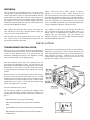
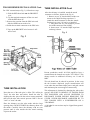
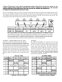
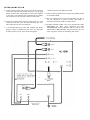
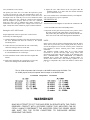
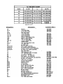
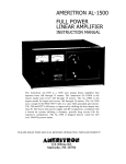
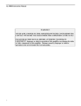
AMERITRON AL-1200
FULL POWER
LINEAR AMPLIFIER
INSTRUCTION MANUAL
The Ameritron AL-1200 is a 1500 watt output linear amplifier
that operates from 160 through 15 meters. The Ameritron AL1200X is the export model and covers 160 through 10 meters.
The AL-1200 uses a single 3CX1200A7 tube in a class AB2
grounded grid circuit. CW, FM and RTTY efficiency is
improved by shifting the bias deeper into class B. The heavy
duty power supply and RF components, combined with a forced
air system utilizing chimneys, provide long service life for
expensive components. The AL-1200 is shipped factory wired
for 240 volt, 50/60 Hz power mains.
PLEASE READ THIS MANUAL BEFORE OPERATING THIS EQUIPMENT!
116 Willow Rd.
Starkville, MS 39759
UNPACKING INSTRUCTIONS
1. Carefully remove the amplifier, transformer, and tube from their shipping cartons.
Inspect each item for visible damage. If any damage occurred during shipment,
notify the transportation company immediately.
2. Save all packing materials in case you need to return your AL-1200(X) for factory
service. The cartons have been designed to give maximum protection for this
amplifier. Any units returned without proper packing may be damaged and
shipping claims cannot be made. Contact the factory before returning any units.
3. Remove the screws that hold the cover to the amplifier. Slide the cover back and
remove it from the amplifier. Remove the package that is in the area where the
transformer will be mounted. This package contains the chimney for the
3CX1200A7. There is also a small package that contains the fuses, fuse caps and
the remainder of the chassis screws.
4. Please read the GENERAL INFORMATION and SPECIFICATIONS sections
before attempting to install the transformer and tube. Go to the INSTALLATION section on page 4 to begin installing the transformer and tube.
5. This amplifier must always be disconnected from the power mains before removing
the cover. See the precaution on page 10. Please read the entire manual to become
familiar with the operation of the AL-1200(X) amplifier.
FEATURES
1. Inexpensive tubes: the AL-1200 uses a single rugged
3CX1200A7 tube.
6. Two Illuminated Panel Meters: the AL-1200 has two illuminated panel meters. . The Grid Current meter provides a continuous reading of grid current and indicates
proper operation of the amplifier. The other meter reads
Plate Voltage (HV), Plate Current (IP), Peak RF Watts
(PO) and ALC.
2. Fast warm-up time:
the 3CX1200A7 requires only a
few seconds of warm-up time.
7. Operate/Standby Switch: filament and plate voltages are
maintained while allowing the amplifier to be bypassed
for "barefoot" operation.
3. SSB/CW switch: the bias voltage is switched to provide
the best linearity on SSB or the lowest dissipation on
CW operation.
4. ALC Indicator: the drive level is detected to provide a
control voltage for the exciter. ALC prevents overdriving of the linear and reduces distortion from excessive drive power.
5. Vernier Plate and Load Adjustments: both tuning controls have vernier 6:1 reduction drives for smooth tuning.
8.12 Volt Auxiliary Jack: 12 volts at 100 mA is provided
for accessories such as the ATR-15 Antenna tuner.
9. XMT Indicator LED: provides a front panel indication of
proper amplifier keying by the exciter during operation.
Caution: This amplifier must be disconnected from the
power mains before removing the cover. See the warning
on page 10.
TECHNICAL SPECIFICATIONS AL-1200*
Input
Circuit type: Pi-network, slug tuned coils
maximum VSWR at resonance: 1.2:1 minimum
2:1 VSWR bandwidth: 20% maximum drive
power permissible: 130 watts typical drive for
full power output: 100 watts
Output
circuit type: Pi-L, Pi
in hour continuous carrier: 1500 watts (Below 18MHz) 30
second continuous carrier: 1800 watts plus
in hour PEP two-tone test: 1800 watts
Power Supply
circuit type: full wave bridge, capacitor input no
load voltage: 3600V
full load voltage. 3300V full load current: .8 amp
regulation: 10% or better transformer: 32 lbs.,
hypersil capacitors: 26 mfd total, computer grade
maximum draw at rated output: 13 amps at 240V
AC, 50/60 Hz
Tube
type: (1) 3CX1200A7
continuous dissipation: 1200 watts
warm-up time: 10 seconds
Metering: multimeter: plate current, plate voltage,
drive/ALC, power output (PEP watts). Grid: grid
current
ALC: negative going, 0-20V, adjustable, phono jack
Efficiency CW: 65% typical
Efficiency SSB (envelope crest): 62% typical
MARS/WARC: yes, bandswitch set to nearest amateur
band
Keying: requires relay closure or sinking to ground of
positive (+) 12 VDC at 100 mA, phono jack
RF Connectors: S0239
Line Connector: NEMA 6-15P 240V style
Dimensions: 181/2" D x 17" W x 10"H
Weight: 77 lbs.
Frequency Coverage: 1.8 through 21 MHz amateur bands
Third Order IMD at Rated Output: -34 dB at 1500 w
output
*
specifications are subject to change without notice or obligation.
GENERAL INFORMATION
SAFETY INTERLOCK
PLATE SUPPLY
While the Amplifier's top cover is in place, the interlock switch
closes to allow AC line voltage to reach the power transformer.
When the top cover is removed, the interlock opens and
disconnects the line voltage. This does not discharge the bank of
power supply filter capacitors. Be sure to allow the filter
capacitors to discharge before you touch anything inside the
Amplifier. You can select the High Voltage function of the
Multimeter to check the high voltage potential. Never attempt to
defeat the safety interlock. WARNING- Never remove the cover
of this amplifier with the unit plugged into the power line.
DRIVING POWER
This Amplifier is designed to operate at full ratings when it is
driven by an exciter that has approximately 100 watts of RF
output. You can use an exciter that has lower output power, but
the Amplifier's output will be less. If you use an exciter that
delivers more than 100 watts, carefully adjust the driving power
to avoid "over drive" and the creation of spurious signals, which
create needless interference to other operators. We highly
recommend that you use a monitor scope for continuous output
monitoring. The display on an oscilloscope is the best way of
determining the amplitude of the voice peaks which, if
excessive, can cause "flat topping" and splatter.
IMPORTANT: In no case should you advance the power output
control of your exciter beyond the point where the Amplifier's
Power Output indication ceases to increase. If you turn the
control past this point, nonlinear operation may occur.
FILAMENT SUPPLY
The plate supply has a full wave bridge rectifier and a 1.8 KVA
CCS rated tape wound hypersil transformer. Filtering is
accomplished by a bank of high quality capacitors totaling 26
mfd (additional capacitance will not improve supply
performance). The Plate Supply will not be harmed by normal
continuous amateur operation at 1500 watt levels. Power is
applied through RLY2 when the 12V DC low voltage supply is
activated. A 10 ohm resistor limits the line current during the
filter capacitor charge time to lower the stress on components.
When the primary voltage approaches the full line value, RLY3
shorts the 10 ohm resistor and applies the full line voltage to the
plate transformer. The 10 ohm resistor acts as a fuse during
start-up if the high voltage supply has a short.
EXPORT MODIFICATIONS
A simple modification will allow operation on frequencies
above 15 meters. Instructions for this modification are available
by sending a written request for "Export Modification
Instructions" along with a copy of a valid amateur license.
There is no charge for this information. Export models are
shipped with this modification and have an "X" following the
serial number. Standard frequency coverages are indicated in
the chart following the tuning instructions on page 6.
TECHNICAL ASSISTANCE
Technical assistance is available during our normal business
hours on weekdays. The following information is required to
assist you with operational problems:
1. Model and Serial Number
The filament circuit of this amplifier satisfies all requirements
of the tube manufacturer related to tube performance and life.
Inrush current is controlled by the transformer internal
resistance and impedance, filament choke resistance and
filament wiring resistance. To insure maximum life of the tube
never replace any circuit components or wiring with substitute
parts.
The low voltage tap on the filament transformer primary provides the ability to operate the blower at slower speeds for
reduced noise. Normal amateur operation in CW and SSB will
not cause heat damage to components on any recommended tap.
It is always advisable to use the maximum speed (air flow) that
the level of noise permits to extend component life. Wiring
information for the blower is shown in the "Transformer
Connections" instructions.
2. Date of purchase and dealer
3. An accurate description of the problem
Meter readings at all stages of the tuning proceedure are very
important along with a complete description of the other
equipment used with our product.
Written assistance is also avaiable. Due to time delays in
processing mail, please allow at least three weeks for a writ
ten reply.
AMERITRON 116
Willow Road
Starkville, MS 39759
Tel: (662) 323-8211
Fax: (662) 323-6551
PERIODIC MAINTENANCE
The high voltage present on the plate choke and air variable
capacitors attracts dust and dirt out of the air stream. It is
particularly important that the high voltage areas at the bottom
of the plate choke and the insulators on the air variable
capacitors be dust free. These areas should be inspected every
few months if the amplifier is operated in a dusty environment.
Unplug the line cord, and wait about 90 seconds until the power
supply capacitors discharge. Remove the cover and connect a
jumper wire from ground to the anode connection of the tubes.
NOTE: This is a safety wire that must be installed when
beginning service work and removed when work is finished.
Use a soft bristle brush dipped in alcohol to clean areas mentioned previously. In the event that cleaning is required at
frequent intervals, place a low restriction air filter material over
the air inlet holes on the left front side of the cabinet near the
filter capacitors. Most hardware stores stock suitable materials
that are used as replacement filters for window air conditioners.
METERING
The AL-1200 has two illuminated meters. The Grid Current
meter provides a continuous indication of the 3CX1200A7 grid
current. This exclusive feature of Ameritron amplifiers indicates
proper amplifier operation better than any other parameter. Do
not exceed 300 mA on this meter during normal operation of
this amplifier. The other meter reads Plate Voltage (HV), Plate
Current (IP), Peak RF Watts (PO) and ALC. These functions are
selected with the Multimeter Switch.
NOTE: This circuit uses an emitter follower to charge a
capacitor to the peak envelope voltage detected by the
ALC/Power Board. Accurate peak envelope power readings are
given when the amplifier is connected to a 50 ohm nonreactive
load. If the amplifier is used with a mismatched load, the power
meter will read higher or lower than normal by a ratio up to the
value of the SWR. Potentiometer R5 on the Meter Board (5001140-1) adjusts the calibration of the power meter.
Plate Voltage (HV): Read DC Plate Voltage on the 4000 volt
scale. This scale is 100 volts per division. Normal voltages are
6
3 00 volts no load, 3300 volts full load.
ALC: Indicates a relative drive level (average, not PEP) that
can be estimated by dividing the Peak RF Watts scale by 10.
NOTE: There is a neutralization tab mounted on a ceramic
standoff near the 3CX1200A7. This tab increases the
amplifier's efficiency on 21 and 28 MHz. DO NOT CHANGE
THE POSITION OF THIS TAB.
Peak RF Watts (PO): Read Peak RF Watts on the 2000 watt
scale. This scale has 50 watt divisions below 1000 watts and
100 watt divisions above 1000 watts.
INSTALLATION
TRANSFORMER INSTALLATION
Remove the cover of the amplifier. Remove the package that is
in the plate transformer area. This is the fuse pack and chimney
for the AL-1200. Remove the top 7/16" nuts from the four
transformer mounting bolts inside of the amplifier. Carefully
remove the transformer from its shipping carton.
Place the transformer on the four 1/4-20 mounting bolts. Use
care because the transformer is heavy. The side with the two
high voltage secondary RED leads must be adjacent to the center
panel(see Fig. 1). Now place a 7/16" nut on each bolt (see Fig.
2). Snug the nuts down manually. Do not tighten with a ratchet
wrench.
Remove the brass 1/4" hex nuts and the top flat washer from the
two brass 6-32 screws on the rectifier board (see Fig. 1). Install
the RED lead ring terminals on the screws and replace the flat
washers and 1/4" hex nuts. Position the wires so that the black
insulated areas are at least 1/4" from each other and any metal
objects. Now tighten the 1/4" hex nuts.
For 240V Operation (factory wired):
The four primary leads have colored plastic insulating boots
over the quick disconnect terminals. Slide these back prior to
installing the leads. Install the color coded boots as follows:(see
Fig. 1)
BLUE (Brown wire) to the top relay terminal
YELLOW (Black/White) to the top terminal of terminal
block
CLEAR (Black wire) to the second terminal of terminal block
RED (Brn/Wht-240V)(Grn-220V) to the bottom terminal of
terminal block
Now slide the colored insulating boots back over the terminals.
Important: The leads must be in the positions indicated by the
color coded insulating boots(see Fig. 1) for 240V operation. For
220V operation, see page 5. Caution: Do not use the 220V
wiring unless the line voltage is always below 220 VAC. The
Standard USA voltage is 240 VAC, not 220.
TRANSFORMER INSTALLATION Cont.
For 220V connections(see Fig. 3), follow these steps
1. Slide the RED boot back on the BRN/WHT
wire
2. Clip the terminal connector off the wire and
slide the RED boot off
3. Remove the restraint from the GRN wire and
slide the RED boot on to the wire.
4. Solder the terminal connector to the GRN wire.
5. Tape up the BRN/WHT wire because it will
not be used.
TUBE INSTALLATION Cont.
After the chimney is installed, attach the anode
connector as follows: (Refer to the Fig. 4)
1. Remove screw "A" that holds the anode connector to the 500pf blocking capacitors. 2.
Attach the anode connector to the tube Anode.
Position it so screw "A" can be re-installed.
3. Snug down nut "B" just enough to prevent
the anode connector from sliding.
4. Insert screw "A" into the 500pf capacitors
and snug it down.
Fig. 4
Fig. 3
Recent production model AL-1200 amplifiers have a
neutralization tab located next to the 3CX-1200A7. This
change results in additional efficiency on 21 and 28
MHz.
TUBE INSTALLATION
Note that one of the tube pins is offset. This offset pin
"keys" the tube base and socket. Install the tube by
aligning the tube pins with the socket contact terminals,
then seat the tube with vertical pressure ONLY. Do not
"rock" or "twist" the tube
Place the chimney over the tube anode with the large
opening down. DO NOT FORCE the chimney down over
the anode. Carefully lower the chimney with an even
pressure until it seats outside the four metal retaining
clips on the socket.
This tab should not be altered in position. In the event
the tab becomes displaced, proper neutralization will
occur when the maximum output power and grid current
and minimum plate current appear concurrently.
This adjustment is obtained by changing the tab to tube
spacing. BE SURE TO REMOVE AC POWER FROM
THE AMPLIFIER AND ALLOW BLEEDERS TO
DISCHARGE POWER BEFORE REMOVING THE
COVER. NEVER DISCHARGE AMPLIFIER HV TO
THE CHASSIS WITH A SCREWDRIVER OR A
"CROWBAR".
A 100 ohm 10 watt resistor may be clipped from ground
to the HV.
Caution: This page is only valid for transformers that contain these exact color codes for the
primary winding. Early production units did not contain a multiple tap transformer. If the terminal
strip has all these color coded wires, then the unit has the multiple tap transformer.
FILAMENT/BLOWER WIRING INSTRUCTIONS
The AL-1200 amplifier comes prewired for 240V line voltage and with the blower prewired for medium high fan speed.
This page gives filament transformer connection details for various line voltages and blower speeds. The five lug terminal
strip and the single lug terminal strip are located immediately behind the ON/OFF rocker switch inside the unit. The
drawing below shows the connection of transformer leads and their purpose.
This chart shows the color code of the transformer leads and their purpose. The number in parenthesis indicates the number of the terminal lug that the transformer lead is connected to. The number
three (3) lug is not used to change the filament or blower wiring. Do not add or remove any wires
from the number three (3) lug. Refer to the drawing above. Use the lug numbers above when referring to both of the Filament connection chart and the Blower connection chart below.
FILAMENT TRANSFORMER LINE VOLTAGE
There are two wires that connect to the terminal lugs
which determine the Filament Line Voltage. The BLACK
wire from the power switch and WHITE wire from rear of
the unit connect to different terminal lugs depending on the
voltage desired. The AL-1200 comes prewired for 240V
operation*. Refer to the chart below. The voltage listed in
the chart below is the maximum line voltage that should be
applied to a given tap. Operation with line voltage in excess
of the tap voltage selected can result in a reduction of tube
life. '
BLOWER
The GREEN and WHITE wires from the rear of the unit
connect to the terminal lugs to control the air speed of the
fan. The AL-1200 is prewired for the medium high speed
setting*. Refer to the chart below. The blower connections
can be moved to lower speed taps if air noise is excessive.
Ameritron recommends using the highest speed tap that
noise considerations permit. The lowest speed tap will
develop sufficient air flow for standard amateur SSB and
CW full power operation. The highest speed taps should be
used for contest or RTTY operation.
INTERCONNECTION
1. Connect the RF output of the exciter to the RF IN connector
on the rear of the AL-1200 with 50 ohm coax. Use any good
quality 50 ohm cable long enough to connect the amplifier
to the exciter. The amplifier uses a standard SO-239 female
that will mate to a PL-259 male connector on the cable.
2. Connect the existing station antenna system to the RF . OUT
connector on the rear of the AL-1200 with RG-8 type coax.
This connection uses PL-259 connectors.
3 . Use shielded audio type cable with standard male phono
plugs to connect to the RELAY jack on the AL-1200. This
jack has positive 12V DC open circuit and supplies
100mA of current when pulled to ground.
4. Connect a short ground lead from a good earth and RF ground
to the GND terminal.
5. The 12V connection on the rear panel provides 12V DC at
100 mA maximum to operate external dial lamps or
accessories such as the ATR-15 Antenna Tuner.
6. DO NOT CONNECT THE "ALC OUT" SOCKET ON THE
AMPLIFIER TO THE "ALC" SOCKET ON THE
TRANSMITTER UNTIL INSTRUCTED TO DO SO IN
THE TUNE UP PROCEDURE. This jack provides up to 20
Volts of negative voltaqe for transmitter gain control.
LOCATION
INSTALLATION Cont.
POWER CONNECTIONS
Do not operate the Amplifier in excessively warm locations
or near heating vents or radiators. Be sure air can circulate
freely around and through the Amplifier cabinet. Provide an
unobstructed air inlet for the blower. Do NOT place anything
that will impede the free flow of air within 2 inches of the
cabinet ventilation holes.
The AL-1200 is supplied with a NEMA 6-15P plug for 240V
AC operation. Operation with power main voltages below
200 volt is not recommended. Special transformers are required for 200V, 50/60 Hz operation. Refer to the
"Transformer Installation" section on pages 4 and 5 for the
correct wiring for 220 to 240 volt operation.
VENTILATION
NEVER REWIRE THE POWER SUPPLY TO BOOST
The AL-1200 ventilation system has been designed and THE HIGH VOLTAGE ABOVE 3700 VOLTS.
tested to maintain tube seal temperature safely below the
tube manufacturer's rating at 1500 watts output with a 100% The wiring between the fuse box and the amplifier AC outlet
duty cycle when properly tuned. The blower in the AL-1200 must be No. 12 gauge or larger in order to supply the current
is a permanently lubricated type that requires no main- required (13 amperes) without a significant drop in the line
tainence in normal operation. To insure proper ventilation in voltage. The outlet should be fused for 20 amperes.
your installation, observe the following:
GROUNDING
1. Do not block or unduly restrict the ventilation holes in the
cover. Be sure that the amplifier is located in an area so
the vent holes have open air circulation.
Connect a good RF and earth or water pipe ground to the
ground post on the rear panel of the Amplifier. Use the
heaviest and shortest connection possible.
2. The exhaust air flow is over 30 CFM. Do not "assist" the
air flow unless the fan exceeds the AL-1200 blower Before you use a water pipe ground, inspect the connections
CFM by a factor of 2:1.
around the water meter and make sure that no plastic or rub3. Do not mount additional fans on the AL-1200 cabinet.
ber hose connections are used. These connections interrupt
electrical continuity to the water supply line. Install a jumper
around any insulating water connections you may find. Use
4. The exhaust air will become quite warm at higher power heavy copper wire and pipe clamps. It is best to ground all
levels. Do not place any heat sensitive objects in the equipment to one point at the operating position and then
exhaust air stream.
ground this point as described above.
TUNING INSTRUCTIONS
Proper tuning of a grounded grid linear amplifier is best
accomplished with an understanding of what each control
does and what the meters are telling the operator about the
condition of TUNE
ing operation. Excessive grid current, distortion on SSB or
arcing in the tank components occurs when full drive power
is applied to the amplifier without the "LOAD" set for
enough clockwise (higher loading).
The tuning controls function as follows:
It is important to remember the loading must be set properly
for the PEAK power the amplifier is expected to develop. 50
watts PEP will be the maximum drive the amplifier will
safely handle if the output of the amplifier is tuned with 50
watts of carrier drive. Any attempt to go beyond the amount
of drive power the amplifier was originally tuned at will
result in a rapid increase in grid current, splatter and even
damage to components.
PLATE: This control tunes the amplifier output circuit to the
operating frequency. It should always be adjusted for
maximum output power or maximum grid current. Due to
interaction with the "LOAD" control, a "touch-up" should be
performed after any load adjustments.
LOAD: This control adjusts the coupling of amplifier to the
antenna or load. It should be adjusted to keep the grid current
in the proper operating range. As the loading capacitance is
reduced (by rotating the control to a higher front panel
number), the coupling is increased. An increase in coupling
will reduce grid current and increase the amount of drive the
amplifier will accept without component damage.
A common mistake in tuning is to adjust the "LOAD"
control at low drive powers and apply more drive dur
The "LOAD" control should be adjusted for maximum
output power without exceeding the recommended grid
current. DO NOT USE THE LOAD CONTROL TO
REDUCE POWER IN A GROUNDED GRID
AMPLIFIER. The drive from the exciter should be reduced
if the amplifier plate current or output power is excessive.
The "LOAD" setting should be increased if grid current is
excessive. Any errors in adjusting this control should be
made in favor of a higher load setting (clockwise).
OPERATION
CW PROCEDURE
Follow these instructions in numerical order. If the various
meter readings are different than indicated, check the connections from the exciter to the amplifier and make sure they
are correct. Consult the manual for the exciter.
6. With exciter drive still at zero, place the MULTIMETER
switch in the Ip position. Observe the 1000 mA scale. The
meter should read zero (0). Place the STBYOPR switch in
the OPR position.
Be sure the transformer is correctly installed and wired for your
line voltage. See the "Transformer Installation" section on page
4 and 5 for wiring details.
7. Key the exciter (no drive) and observe the plate current on
the 1000 mA scale. It should be 40 mA. Place the CW-SSB
switch in the SSB position. Plate current should now read
150 mA. Return the CW-SSB switch to the CW position.
1. Set the AL-1200 front panel switches as follows:
POWER TO OFF
OPR-STBY TO
STBY SSB-CW TO
CW MULTIMETER
2. Plug the AC line cord into the proper voltage outlet.
3. Set the Power Switch to the ON position. The meter lamps
should light and the blower should start. Read the 4000 volt
scale on the Multimeter. It should indicate 3600 volts
nominal and no more than 3700 volts.
Note: The no drive currents will vary up to 25% due to
component and line voltage tolerences.
8. Apply only enough drive to indicate a grid current of 100 mA
or an Ip of no more than 500mA. Tune the PLATE control
for maximum output power or grid current. It is normal for
the plate current to dip at this point. If the grid current goes
over 150 mA, reduce the drive at once. Unkey the exciter.
4. With the amplifier still on STANDBY, tune the exciter into a
normal 50 ohm load according to the manufacturer's
instructions. Turn the exciter drive fully down after tuning.
9. Place the MULTIMETER switch in the PO position and
observe the 2000 Peak RF Watts scale. Increase the drive
until 200 mA of grid current is indicated. Adjust the LOAD
and PLATE controls for maximum output. The grid current
may be lower now.
5. Place the amplifier mode switch in the CW position, the
bandswitch on the same band as the exciter, the PLATE
control in the dial range for the band selected and the load
control as indicated:
10. Advance the drive to 250 mA of grid current. Adjust the
LOAD and PLATE controls for maximum output power.
(Repeat this step twice). The output should be over 1000
watts now.
11. Apply enough drive to indicate either 1500 watts of output
power or 300 MA of grid current. Re-peak the LOAD and
PLATE controls. The final grid current should be around
250 mA and the plate current below 900 mA.
ALC (Automatic Level Control)
The primary use of the ALC is to reduce the input drive power
to a safe level for the AL-1200. The maximum drive of the AL1200 will tolerate is approximately 130 watts. At this drive level
the output of the AL-1200 may be in excess of 2000 watts when
properly tuned. The ALC should be connected and adjusted
after the amplifier is properly tuned on CW. Use a shielded
audio-type cable with a standard male phono connector to
connect the 0-20 volt negative ALC voltage to the exciter ALC
input. Consult the exciter manual for proper connection details.
6. Adjust the ALC ADJ control on the rear panel until the
amplifier output is no more than the desired maximum
power obtained in step 1.
The exciter internal ALC will maintain linearity. The amplifier
ALC will prevent over-power operation.
SSB PROCEDURE
Tune the Exciter and Amplifier as described in "TUNE-UP CW
1. Place the SSB-CW switch in the SSB position.
Setting the ALC ADJ Control
Proper adjustment of the rear panel ALC control can be
achieved by the following steps:
1. Load the amplifier according to the tune-up instructions (with
the ALC disconnected from the exciter) to the desired
maximum power.
2. Connect the ALC line and rotate the ALC control fully
clockwise looking at the rear of the unit.
3. Set the MULTIMETER switch to the PO position or observe
an external PEP meter or oscilloscope.
4. Set the transmitter audio control about 20% higher than
normal
5. Speak in the microphone in a normal tone of voice and
observe the reading on the 2000 RF Watts scale.
2. Adjust the exciter gain control to permit voice peaks to reach
the same value the peak output meter read on CW when
fully loaded. The plate and grid currents should remain well
below 50% of the CW values during normal modulation.
NOTE: ,
Some exciters will put out short duration high power RF pulses
when first keyed. Exciter power output peaks may reach or
exceed full output level even if the exciter's power control has
been adjusted to deliver reduced power under "keydown"
conditions.
The amplifier loading control must be set high enough
(clockwise) to prevent extremely high energy levels from
developing in the plate and grid circuits of the amplifier. DO
NOT "UNDERLOAD" THE AMPLIFIER TO REDUCE
POWER. Never "retune" the amplifier to produce higher efficiency with reduced drive. Poor linearity, splatter or even
damage to components may result from failure to follow these
i t ti
The AL-1200 will operate with full output on all WARC bands except 24.5 MHz. The
AL-1200X (export model) will operate with full output on all WARC bands.
STANDARD FREQUENCY COVERAGE
WARNING!!!
MAKE NO ATTEMPT TO PUT THIS AMPLIFIER IN SERVICE WITH THE COVER
REMOVED! CONTACT WITH VOLTAGES INSIDE THIS AMPLIFIER CAN BE
FATAL! ALWAYS DISCONNECT THE AMPLIFIER FROM THE POWER MAINS
AND WAIT FOR THE FILTER CAPACITORS TO DISCHARGE BEFORE
REMOVING THE COVER.
PARTS LIST