1
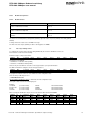
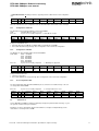
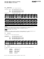
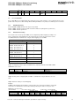
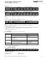
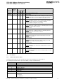
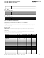
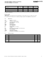
RFC-4800 CANopen Gebrauchsanleitung
RFC-4800 CANopen user manual
NOVOtechnik
SIEDLE GRUPPE
Content
5
CANopen
2
5.1
EDS Files
2
5.2
5.2.1
5.2.2
5.2.3
5.2.4
5.2.5
Features
Basic information
Basics based on CiA DS-301, V4.2.0
Basics based on CiA DSP-406, V3.2
Basics SDO communication
Basics PDO communication
2
2
2
3
3
3
5.3
5.3.1
5.3.2
5.3.3
Object Library
Communication Profile Area based on DS 301 V4.2.0
Device Profile Area
Manufacturer specific Area
4
4
6
8
5.4
5.4.1
5.4.2
5.4.3
5.4.4
5.4.5
5.4.6
5.4.6.1
5.4.6.2
Explanations to Object Library
Object 0x6000 Operating Parameter
Object 0x6001 Measuring Step per Revolution
Object 0x6002 Total Measuring Range in measuring units
Object 0x6300 Encoder Cams
Cam state registers
Object 0x6400 Work Area
Work Area Supervision
Work Area State
9
9
9
9
9
9
9
10
10
5.5
5.5.1
5.5.2
5.5.3
LSS / Layer Setting Service
Configuration of Node-ID
Configuration of Bit Rate
Store Configuration Data
10
11
11
11
5.6
5.6.1
5.6.2
5.6.3
SDO Services
SDO Download
SDO Upload
SDO Abort
11
12
12
12
5.7
5.7.1
5.7.2
Process Data PDO
PDO Default Setting
PDO Parameter Setting
13
13
13
5.8
5.8.1
Error Handling
Emergency Messages
14
14
5.9
5.9.1
5.9.2
5.9.3
Error Objects
Manufacturer-specific Status
Alarms
Warnings
15
15
16
16
5.10
Non-Volatile Storage and Data Restoration
16
5.11
Abbreviations
17
5.12
Document Changes
17
Version 00
2014/07 Änderungen vorbehalten / Specifications subject ot change
1
RFC-4800 CANopen Gebrauchsanleitung
RFC-4800 CANopen user manual
NOVOtechnik
SIEDLE GRUPPE
5 CANopen
This document reflects the Novotechnik sensor protocol implementation of the standard CANopen protocol.
A basic knowledge of the CAN Bus is required for a proper understanding of this document.
Most of the definitions made are according to the following CiA Standard specifications.
For making use of all the features that these specifications offer, a knowledge about them is absolutely necessary.
The sensor supports the CANopen Communication profile DS-301, V4.2.0, Encoder profile DSP-406, V3.2 and
Layer Setting Services (LSS) DSP-305, V1.1.2.
5.1 EDS Files
For integration in a common CANopen projecting tool, electronic data sheet (*.eds) files are provided.
These files can be downloaded from the Novotechnik Web Site, see Downloads/Operating manuals
where also this document can be found.
Electric data sheet see file RFC48.eds
5.2
Features
5.2.1
Basic information
Vendor ID:
Product code:
386 = 0x0182 (Novotechnik)
03040 = 0x0BE0
Rev.-No.:
f.e 65539 = 0x10003, see product label “XXXXX” (5 characters)
Serial No.:
see product label, “B/N XXXXXX/YYY” (6+3 characters)
5.2.2
Basics based on CiA DS-301, V4.2.0
CAN Identifier
CAN Bit rates
Node-ID
Standard 11 bit according to pre-defined connection set:
Services
COB-ID
NMT
0x00
SYNC
0x080
EMCY
0x080 + Node-ID
PDO1 (Tx)
0x180 + Node-ID
PDO2 (Tx)
0x280 + Node-ID
SDO (Rx)
0x600 + Node-ID
SDO (Tx)
0x580 + Node-ID
Bit rate is defined in the ordering code:
6_7: 50 kBaud
6_5: 125 kBaud
6_4: 250 kBaud
6_3: 500 kBaud
6_2: 800 kBaud
6_1: 1000 kBaud
setting per LSS (see chapter 5.5 LSS / Layer Setting Service) or object 0x2001 (see chapter 5.6 SDO Services)
0x7F
setting per LSS (see chapter 5.5 LSS / Layer Setting Service) or object 0x2001 (see chapter 5.6 SDO Services)
SYNC
Consumer
Time Stamp
no
Emergency Messages
Producer
Node Guarding
yes
Heartbeat
Producer
Non-volatile storage
yes
Program Download
no
NMT Service
Slave
Version 00
2014/07 Änderungen vorbehalten / Specifications subject ot change
2
NOVOtechnik
RFC-4800 CANopen Gebrauchsanleitung
RFC-4800 CANopen user manual
5.2.3
SIEDLE GRUPPE
Basics based on CiA DSP-406, V3.2
Encoder class
C1
C2
Encoder type
Absolute Rotary Multi Sensor Encoder Interface
Max. bit bandwidth of position value
14 bit
Encoder Cams
Channels to be detected
Cams per channel
Polarity
Hysteresis
Pos.ch1, Pos.ch2
4
invertable
yes
Work Area Supervision
channels
Pos.ch1, Pos.ch2
5.2.4
Basics SDO communication
SDO communication
1 Server
expedited transfer
yes
segmented transfer
no
Block transfer
no
5.2.5
Basics PDO communication
PDO communication principle
Producer
TPDO1:
asynchronous with Event Timer,
synchronous
TPDO2:
synchronous
TPDO‘s
PDO Mapping
dynamic
max. PDO Mapping logs per PDO
5
Version 00
2014/07 Änderungen vorbehalten / Specifications subject ot change
3
NOVOtechnik
RFC-4800 CANopen Gebrauchsanleitung
RFC-4800 CANopen user manual
5.3
SIEDLE GRUPPE
Object Library
5.3.1
Communication Profile Area based on DS 301 V4.2.0
Object description
Index/
Entry description
Name
Data Type
Access
PDO
Mapping
Default value
Comment
1000
device type
unsigned32
const
no
0x00010196
1001
1002
error register
manufacturer
status register
COB-ID SYNC
unsigned8
unsigned32
ro
ro
no
no
0x00
0
unsigned32
rw
no
0x00000080
visible_ string
const
no
f.e. RFC-4801214-614-511
visible_ string
const
no
f.e. V 1.00
visible_ string
const
no
f.e. V 1.03
Software version release
100C
manufacturer
device name
manufacturer
hardware version
manufacturer
software version
guard time
Device profile 406 multi-sensor
encoder interface
See chapter 5.8 Error Handling
Additional manufacturer spec. status
register
COB-ID SYNC message (CANidentifier)
Device name, see datasheet/ordering
code
Hardware version release
unsigned16
rw
no
0x00000000
disabled
100D
life time factor
unsigned8
rw
no
0x00000000
disabled
1010
store parameter
field
unsigned32
1010/1
1010/2
1010/3
1010/4
store parameter
field
unsigned32
unsigned32
unsigned32
unsigned32
rw
rw
rw
rw
no
no
no
no
0x00000000
0x00000000
0x00000000
0x00000000
1011
restore default
parameters
unsigned32
Time base (in ms), which gives
combined with 100D the time in
which the response of the node
guard is expected
The life time factor multiplied with the
guard time gives the life time for the
device.
This entry supports saving of parameters in non volatile memory.
With a read access the device provides information about its saving
capabilities.
For saving the signature "save"
(0x65766173) must be written.
Save all parameters
Save communcation parameters
Save application parameters
Save manufacturer defined parameters
This entry supports restoring of
default parameters. With a read
access the device provides information about its capabilities to restore these values.
For restoring the signature "load"
(0x64616f6c) must be written.
Restore all default parameters
Restore communication default
parameters
Restore application default parameters
Restore manufacturer defined parameters
COB-ID used for emergency message (Emergency Server).
Heartbeat time periode in ms.
Range 0...0xFFFF
General information about the device.
This information is also used as the
LSS address when using “switch
mode selective” command
Vendor ID
Product code
subindex
1005
1008
1009
100A
1011/1
1011/2
unsigned32
unsigned32
rw
rw
no
no
0x00000000
0x00000000
1011/3
unsigned32
rw
no
0x00000000
1011/4
unsigned32
rw
no
0x00000000
0x00000080
+ Node-ID
0x00000000
disabled
1014
COB-ID EMCY
unsigned32
ro
no
1017
producer heartbeat time
identify object
unsigned16
rw
no
1018
identity
1018/1
1018/2
unsigned32
unsigned32
ro
ro
no
no
1018/3
unsigned32
ro
no
1018/4
unsigned32
ro
Version 00
0x00000182
0x0 (see
5.2.1Basic
information)
(see
5.2.1Basic
information)
(see
5.2.1Basic
information)
2014/07 Änderungen vorbehalten / Specifications subject ot change
Revision number
Serial number
4
NOVOtechnik
RFC-4800 CANopen Gebrauchsanleitung
RFC-4800 CANopen user manual
Object description
Index/
Name
Data Type
transmit PDO
communication
parameter 1
PDO_COMM
_PAR
Entry description
Access
subindex
1800
SIEDLE GRUPPE
PDO
Mapping
Default value
1800/1
unsigned32
rw
no
1800/2
unsigned8
rw
no
1800/3
1800/4
1800/5
unsigned16
unsigned8
unsigned16
rw
rw
rw
no
no
no
0x0
0x00
0x0
disabled
unsigned32
unsigned8
unsigned16
PDO_
MAPPING
rw
rw
rw
no
no
no
0x40000280
0x1
0x0
1A00/0
1A00/1
unsigned8
unsigned32
rw
rw
no
no
0x02
0x60200120
1A00/2
unsigned32
rw
no
0x602002201)
0x603001202)
1A00/3
1A00/4
1A00/5
1A01
rw
rw
rw
no
no
no
0x00000000
0x00000000
0x00000000
TPDO mapping
parameter 2
unsigned32
unsigned32
unsigned32
PDO_
MAPPING
TPDO mapping
parameter 2
unsigned8
unsigned32
rw
rw
no
no
0x02
0x60200120
1A01/2
unsigned32
rw
no
0x602002201)
0x603001202)
1A01/3
1A01/4
1A01/5
1F80
unsigned32
unsigned32
unsigned32
unsigned32
rw
rw
rw
rw
no
no
no
no
0x00000000
0x00000000
0x00000000
0x0
1801
1801/1
1801/2
1801/3
1A00
1A01/0
1A01/1
1)
2)
transmit PDO
communication
parameter 2
TPDO mapping
parameter 1
NMT startup
0x40000180
+ Node ID
0xFE =254
PDO_COMM
_PAR
Comment
It contains the communication parameters of the current PDO the
device is able to transmit.
COB-ID of the PDO
Transmission type,
asynchronous 254, synchronous
1...239 acc. CiA DS 301
Inhibit Time in 100µs
Compatibility entry
Event timer in ms
Range 1...65535
It contains the communication parameters of the current PDO the
device is able to transmit.
COB-ID of the PDO
Transmission type, synchronous
Inhibit Time in 100µs
Contains the mapping for the PDOs
the device is able to transmit
Number of entries
Mapping entry 1,
default: Position value channel 1
Mapping entry 2,
default: Position value channel 2 1)
default: Speed value channel 1 2)
Mapping entry 3
Mapping entry 4
Mapping entry 5
Contains the mapping for the PDOs
the device is able to transmit
Number of entries
Mapping entry 1,
default: Position value channel 1
Mapping entry 2,
default: Position value channel 2 1)
default: Speed value channel 1 2)
Mapping entry 3
Mapping entry 4
Mapping entry 5
This object determines the startup
behavior of a device in the network.
Bit 3 set: sensor starts in operational
mode
for one-channel version
for two-channel version
Version 00
2014/07 Änderungen vorbehalten / Specifications subject ot change
5
NOVOtechnik
RFC-4800 CANopen Gebrauchsanleitung
RFC-4800 CANopen user manual
5.3.2
SIEDLE GRUPPE
Device Profile Area
* for one-channel version: default value 0x01
** for one-channel version: not available
Object description
Index/
Entry description
Name
Data Type
Access
PDO
Mapping
Default value
Comment
6000
operating
parameter
unsigned16
rw
no
0x0
6001
measuring units
per revolution
unsigned32
rw
no
0x4000
6002
total measuring
range in
measuring units
preset value
unsigned32
rw
no
0x4000
ro
rw
rw
no
no
no
0x02*
0x0
0x0**
ro
ro
ro
no
yes
yes
0x2*
0x0
0x0**
ro
ro
ro
rw
no
yes
yes
no
0x2*
0x0
0x0**
0x0
ro
ro
ro
no
yes
yes
0x2*
0x0
0x0**
ro
rw
rw
no
no
no
0x2*
0x0
0x0**
ro
rw
rw
no
no
no
0x2*
0x0
0x0**
ro
rw
rw
no
no
no
0x2*
0x00
0x00**
This object contains the functions for
code sequence, commissioning
diagnostic control and scaling function control
Object sets the number of distinguishable steps per revolution (singleturn resolution)
Object sets the number of distinguishable steps over the total measuring range (total resolution)
This object supports adaption of the
encoder zero point to the mechanical
zero point of the system
Number of available channels
Preset value channel 1
Preset value channel 2
This object defines the output position value
Number of available channels
Position value channel 1
Position value channel 2
This object defines the output speed
value
Number of available channels
Speed value channel 1
Speed value channel 2
defines the transmission period (in
ms) for asynchronous PDO, mapped
to object 0x1800/5
defines the status bit of the cam in a
cam channel. The bit value 0 means
"cam inactive". The bit value 1 means
"cam active". If the polarity bit of a
cam is set the actual cam state will
be inverted.
Number of available channels
CAM state channel 1
CAM state channel 2
This object contains the calculation
state for 4 cams for one position
channel.
If the enable bit is set to 1, the cam
state will be calculated by the device.
In the other case the cam state of the
related cam will be set permanently
to 0.
Number of available channels
CAM enable channel 1
CAM enable channel 2
This object contains the actual
polarity settings for 4 cams for one
position channel. If the polarity bit is
set to 1, the cam state of an active
cam will signal by setting the related
cam state bit to zero. In the other
case the cam state of the related cam
will not be inverted.
Number of available channels
CAM polarity channel 1
CAM polarity channel 2
determines the lower limit of position
for cam 1
Number of available channels
CAM 1 low limit channel 1
CAM 1 low limit channel 2
subindex
6010
6010/0
6010/1
6010/2
6020
6020/0
6020/1
6020/2
6030
6030/0
6030/1
6030/2
6200
6300
6300/0
6300/1
6300/2
6301
6301/0
6301/1
6301/2
6302
6302/0
6302/1
6302/2
6310
6310/0
6310/1
6310/2
Version 00
integer32
position value
integer32
integer32
integer32
speed value
integer32
integer32
unsigned
cyclic timer value
integer16
integer16
unsigned16
CAM state
register
CAM enable
unsigned8
unsigned8
unsigned8
unsigned8
CAM enable
CAM polarity
register
CAM 1 low limit
unsigned8
unsigned8
unsigned
unsigned8
unsigned8
integer32
integer32
Integer32
2014/07 Änderungen vorbehalten / Specifications subject ot change
6
NOVOtechnik
RFC-4800 CANopen Gebrauchsanleitung
RFC-4800 CANopen user manual
Object description
Index/
Name
Data Type
Entry description
Access
subindex
6311
6311/0
6311/1
6311/2
6312
6312/0
6312/1
6312/2
6313
6313/0
6313/1
6313/2
6320
6320/0
6320/1
6320/2
6321
6321/0
6321/1
6321/2
6322
6322/0
6322/1
6322/2
6323
6323/0
6323/1
6323/2
6330
6330/0
6330/1
6330/2
6331
6331/0
6331/1
6331/2
6332
6332/0
6332/1
6332/2
6333
6333/0
6333/1
6333/2
6400
6400/0
6400/1
6400/2
6401
6401/0
6401/1
6401/2
Version 00
CAM 2 low limit
integer32
CAM 3 low limit
integer32
Integer32
integer32
CAM 4 low limit
integer32
Integer32
integer32
CAM 1 high limit
integer32
Integer32
integer32
CAM 2 high limit
integer32
Integer32
integer32
CAM 3 high limit
integer32
Integer32
integer32
CAM 4 high limit
integer32
Integer32
integer32
CAM 1
hysteresis
CAM 2
hysteresis
CAM 3
hysteresis
CAM 4
hysteresis
area state
register
work area low
limit
integer32
Integer32
unsigned16
unsigned16
unsigned16
unsigned16
unsigned16
unsigned16
unsigned16
unsigned16
unsigned16
unsigned16
unsigned16
unsigned16
unsigned8
unsigned8
unsigned8
integer32
integer32
integer32
SIEDLE GRUPPE
PDO
Mapping
Default value
ro
rw
rw
no
no
no
0x2*
0x00
0x00**
ro
rw
rw
no
no
no
0x2*
0x00
0x00**
ro
rw
rw
no
no
no
0x2*
0x00
0x00**
ro
rw
rw
no
no
no
0x2*
0x3FFF
0x3FFF**
ro
rw
rw
no
no
no
0x2*
0x3FFF
0x3FFF**
ro
rw
rw
no
no
no
0x2*
0x3FFF
0x3FFF**
ro
rw
rw
no
no
no
0x2*
0x3FFF
0x3FFF**
ro
rw
rw
no
no
no
0x2*
0x0
0x0**
ro
rw
rw
no
no
no
0x2*
0x0
0x0**
ro
rw
rw
no
no
no
0x2*
0x0
0x0**
ro
rw
rw
no
no
no
0x2*
0x0
0x0**
ro
ro
ro
no
yes
yes
0x2*
0x0
0x0**
ro
rw
rw
no
no
no
0x2*
0x00
0x00**
2014/07 Änderungen vorbehalten / Specifications subject ot change
Comment
determines the lower limit of position
for cam 2
Number of available channels
CAM 2 low limit channel 1
CAM 2 low limit channel 2
determines the lower limit of position
for cam 3
Number of available channels
CAM 3 low limit channel 1
CAM 3 low limit channel 2
determines the lower limit of position
for cam 4
Number of available channels
CAM 4 low limit channel 1
CAM 4 low limit channel 2
determines the higher limit of position
for cam 1
Number of available channels
CAM 1 high limit channel 1
CAM 1 high limit channel 2
determines the higher limit of position
for cam 2
Number of available channels
CAM 2 high limit channel 1
CAM 2 high limit channel 2
determines the higher limit of position
for cam 3
Number of available channels
CAM 3 high limit channel 1
CAM 3 high limit channel 2
determines the higher limit of position
for cam 4
Number of available channels
CAM 4 high limit channel 1
CAM 4 high limit channel 2
This object contains the delay setting
of switch points for cam 1
Number of available channels
CAM 1 hysteresis channel 1
CAM 1 hysteresis channel 2
This object contains the delay setting
of switch points for cam 2
Number of available channels
CAM 2 hysteresis channel 1
CAM 2 hysteresis channel 2
This object contains the delay setting
of switch points for cam 3
Number of available channels
CAM 3 hysteresis channel 1
CAM 3 hysteresis channel 2
This object contains the delay setting
of switch points for cam 4
Number of available channels
CAM 4 hysteresis channel 1
CAM 4 hysteresis channel 2
This object contains the actual area
status of the encoder position.
Bit meaning
0
out of range
1
range overflow
2
range underflow
Number of available work areas
Work area state channel 1
Work area state channel 2
This object contains the lower limit of
the work area
Number of available work areas
Low limit work area 1
Low limit work area 2
7
NOVOtechnik
RFC-4800 CANopen Gebrauchsanleitung
RFC-4800 CANopen user manual
Object description
Index/
Name
Data Type
Entry description
Access
subindex
6402
6402/0
6402/1
6402/2
6500
work area high
limit
operating status
SIEDLE GRUPPE
PDO
Mapping
Default value
integer32
integer32
integer32
unsigned16
ro
rw
rw
ro
no
no
no
no
0x2*
0x3FFF
0x3FFF**
0x0
6501
measuring units
per resolution
unsigned32
ro
no
0x4000
6502
number of
distinguishable
revolutions
unsigned16
ro
no
6503
alarms
unsigned16
ro
yes
Singleturn:
0x1
Multiturn:
f.e 0x16
0x0
6504
supported alarms
unsigned16
ro
no
0x1001
6505
warnings
unsigned16
ro
yes
0x0
6506
supported
warnings
profile and
software version
unsigned16
ro
no
0x1000
unsigned32
ro
no
f.e.
0x01020302
offset value
integer32
650C/1
integer32
ro
650C/2
integer32
ro
* for one-channel version: default value 0x01
** for one-channel version: not available
no
no
0x0
0x0
6507
650C
5.3.3
This object contains the higher limit of
the work area
Number of available channels
High limit work area 1
High limit work area 2
This gives information on encoder
internal programmed parameters.
This object gives the number of steps
per revolution that are output for the
absolute singleturn position value.
This object contains the number of
distinguishable revolutions that the
multiturn-encoder can output.
f.e. Multiturn with 16 revolutions
This object shows, which alarm is
active
This object informs on alarms supported by the encoder
This object reports warnings.
This object informs on warnings
supported by the encoder
This object reports the versions:
byte 3-2: software version
byte 1-0: profile version
The offset value is calculated by the
preset function in object 6010 and
shifts the position value with the
calculated value. The offset value is
stored and can be read from the
encoder for diagnostics.
Offset value channel 1
Offset value channel 2
Manufacturer specific Area
Object description
Index/
Comment
Entry description
Name
Data Type
Access
PDO
Mapping
Default value
Comment
2000
node-ID
unsigned8
rw
no
0x7F
2001
CAN bit rate
unsigned16
rw
no
2002
chip temperature
integer16
ro
yes
See
datasheet/
odering code
f.e. 250=0x03
f.e. 37
Node-ID of the sensor
Range 1...127
CAN bit rate of the sensor in kbit/s
f.e. RFC-4801-214-614-511
250kBaud
2003
2004
ordering
custom
unsigned16
unsigned16
subindex
Version 00
2014/07 Änderungen vorbehalten / Specifications subject ot change
Temperature from inside the µC in
Celsius f.e. at ambient temperature
Manufacturer defined array
Manufacturer defined array, not
writable for the customer
8
RFC-4800 CANopen Gebrauchsanleitung
RFC-4800 CANopen user manual
5.4
NOVOtechnik
SIEDLE GRUPPE
Explanations to Object Library
5.4.1
Object 0x6000 Operating Parameter
This object contains the function for the counting direction.
The counting direction clockwise (cw) or counterclockwise (ccw) is defined whether the signal values are rising or falling when sensor shaft or position marker is rotated cw (view on the position marker or shaft).
Bit 0 = 0: counting direction cw
Bit 0 = 1: counting direction ccw
This object also includes the switching on and off of the scaling function, which is required to change the sensor
resolution.
Bit 2 = 0: scaling off
Bit 2 = 1: scaling on (further scaling is done by objects 0x6001 or 0x6002)
This object also includes the moving average function for position and speed calculation:
Bit 14...12 = 0: moving average function off
Bit 14...12 = n: moving average over 2^n values (n= 1...7)
5.4.2
Object 0x6001 Measuring Step per Revolution
This object sets the number of distinguishable steps per revolution.
Writing is only possible if scaling (0x6000 / Bit 2) is on. Changes of this objects also changes object 0x6002.
The default value is 0x3FFF (14bit) is the maximum step size per revolution. The resolution can only be reduced.
5.4.3
Object 0x6002 Total Measuring Range in measuring units
This object sets the number of distinguishable steps over the total measuring range. Writing is only possible if scaling
(0x6000 / Bit 2) is on. Changes of this objects also changes object 0x6001.
The default value is 0x3FFF (14bit) is the maximum total step size. The resolution can only be reduced.
5.4.4
Object 0x6300 Encoder Cams
Encoder cams are used to indicate if a position falls below or exceeds a defined value.
5.4.5
Cam state registers
Cam active:
Cam inactive:
the current position value is between the higher and lower cam-limit
the current position value is not between the higher and lower cam-limit.
The values for low limit (0x631x) and high limit (0x632x) regard the values for preset (0x6010) and measuring units
per resolution (0x6001). The value of hysteresis (0x633x) is added in direction of motion.
Note:
The cam high limit value can have a lower value than the cam low limit
A change in cam state causes an EMCY message.
The cam state objects (0x6300) are able to be mapped to the TPDOs.
5.4.6
Object 0x6400 Work Area
It is possible for encoders to define a so-called user defined working area.
The main purpose for a work area is to get a high-priority information (via EMCY message) when the transducer’s position leaves its predefined working area.
The actual work area information with work area low limit and work area high limit may be stored in object 0x6401 and
0x6402. This way, the area state object (0x6400) may also be used as software limit switches.
Version 00
2014/07 Änderungen vorbehalten / Specifications subject ot change
9
NOVOtechnik
RFC-4800 CANopen Gebrauchsanleitung
RFC-4800 CANopen user manual
5.4.6.1
Work Area Supervision
5.4.6.2
Work Area State
SIEDLE GRUPPE
Condition
State register 0x6400
Position < Work Area Low Limit
Position >= Work Area Low Limit
Bit 2 = 1
Bit 2 = 0
Position > Work Area High Limit
Position <= Work Area High Limit
Bit 1 = 1
Bit 1 = 0
Position <= Preset Value or Position >= Sensor length
otherwise
Bit 0 = 1
Bit 0 = 0
The values for low limit (0x6401) and high limit (0x6402) regard the values for preset (0x6010) and scaling (0x6501,
0x6502).
A change in work area state causes an EMCY message.
The work area state objects (0x6400) are able to be mapped to the TPDOs.
5.5
LSS / Layer Setting Service
To configure the encoder via the LSS (according CiA DS 305) the encoder is handled as a slave, the
PLC must have a LSS master functionality.
A LSS-message is composed as follows:
DLC
COB-ID
Command
Byte0
Byte1
Byte2
Byte3
Byte4
Byte5
Byte6
Byte5
0x00
Byte6
0x00
This applies to the COB-ID:
• LSS-Master ⇒ LSS-Slave: 2021 (0x7E5)
• LSS-Slave ⇒ LSS-Master: 2020 (0x7E4)
LSS can only be used when the encoder is in the stopped status or pre-operational status.
The NMT command for setting the encoder in stopped status is:
COB-ID
0x7E5
DLC
8
Command
0x04
Byte0
0x00
Byte1
0x00
Byte2
0x00
Byte3
0x00
Byte4
0x00
To program via LSS the sensor has to be switched to LSS configuration state.
There are two possible ways to do so:
• Switch Mode Selective:
only the addressed CANopen device is switched to the LSS configuration state
LSS requires data content in the following objects:
Example:
Vendor-ID
Product code
Rev.No.
Serial-No.
(see index 1018/1)
(see index 1018/2)
(see index 1018/3)
(see index 1018/4)
0x0182
0x0BE0
0x10003
0x12345678
LSS-Command 0x40
LSS-Command 0x41
LSS-Command 0x42
LSS-Command 0x43
After receiving the identification objects, the encoder answers with LSS-Command 0x44.
COB-ID
0x7E5
0x7E5
0x7E5
0x75E
0x7E4
Version 00
DLC
Rx/
Tx
8
8
8
8
8
Rx
Rx
Rx
Rx
Tx
Command
0x40
0x41
0x42
0x43
0x44
Byte0
Byte1
Byte2
Byte3
Byte4
Byte5
Byte6
0x82
0xE0
0x03
0x78
0x00
0x01
0x0B
0x00
0x56
0x00
0x00
0x00
0x01
0x34
0x00
0x00
0x00
0x00
0x12
0x00
0x00
0x00
0x00
0x00
0x00
0x00
0x00
0x00
0x00
0x00
0x00
0x00
0x00
0x00
0x00
2014/07 Änderungen vorbehalten / Specifications subject ot change
10
NOVOtechnik
RFC-4800 CANopen Gebrauchsanleitung
RFC-4800 CANopen user manual
SIEDLE GRUPPE
• Switch Mode Global: all CANopen devices supporting LSS are switched to the LSS configuration
state
COB-ID
0x7E5
DLC
Rx/
Tx
8
Rx
Command
0x04
Byte0
Byte1
Byte2
Byte3
Byte4
Byte5
Byte6
0x82
0x01
0x00
0x00
0x00
0x00
0x00
When the CAN devices are in configuration state the Node-ID and/or the baud rate can be changed.
5.5.1
Configuration of Node-ID
The Node-ID can be programmed with the LSS-Command 0x11
N ID:
new Node-ID in the range of 1...127
Err Code:
0: protocol successfully completed / 1: Node-ID out of range
COB-ID
0x7E5
0x7E4
DLC
Rx/
Tx
8
8
Rx
Tx
Command
0x11
0x11
Byte0
Byte1
Byte2
Byte3
Byte4
Byte5
Byte6
N ID
Err Code
0x00
0x00
0x00
0x00
0x00
0x00
0x00
0x00
0x00
0x00
0x00
0x00
Change of Node-ID will cause:
• Automatic alteration of COB-ID’s for SDO1, EMCY and Heartbeat and TPDOs.
• Non-volatile Node-ID storage through „Store Configuration“ in the LSS mode configuration.
5.5.2
Configuration of Bit Rate
The Bit Rate can be programmed with LSS-Command 0x13
Table Index:
0x06: 50 kBaud
0x04: 125 kBaud
0x03: 250 kBaud
0x02: 500 kBaud
0x01: 800 kBaud
0x00: 1000 kBaud
Err Code:
0: protocol successfully completed
1: Bit timing not supported
COB-ID
Command
DLC
Rx/
Tx
0x75E
8
Rx
0x13
0x74E
8
Tx
0x13
Byte0
Table
Index
Err Code
Byte1
Byte2
Byte3
Byte4
Byte5
Byte6
0x00
0x00
0x00
0x00
0x00
0x00
0x00
0x00
0x00
0x00
0x00
0x00
Change of Bit rate will cause:
• The bit rate gets active
• Non-volatile CAN bit rate storage through „Store Configuration“ in the LSS mode configuration
5.5.3
Store Configuration Data
The LSS configuration data (Node-ID and Bit Rate) are stored to the non-volatile memory of the sensor using LSS-Command 0x17
Err Code:
COB-ID
0x75E
0x74E
5.6
0: protocol successfully completed
DLC
Rx/
Tx
8
8
Rx
Tx
Command
0x17
0x17
Byte0
0x00
Err Code
2: storage media access error
Byte1
Byte2
Byte3
Byte4
Byte5
Byte6
0x00
0x00
0x00
0x00
0x00
0x00
0x00
0x00
0x00
0x00
0x00
0x00
SDO Services
Service Data Objects SDO (according to CiA DS 301) manage the parameter data exchange, e.g. the
non-cyclical execution of the preset function.
Parameters of device object library (object index/subindex see chapter 5.3 Object Library) can be
read, written or stored by means of SDO.
Version 00
2014/07 Änderungen vorbehalten / Specifications subject ot change
11
NOVOtechnik
RFC-4800 CANopen Gebrauchsanleitung
RFC-4800 CANopen user manual
5.6.1
SIEDLE GRUPPE
SDO Download
The SDO download service is used to configure the parameters.
Command 0x2_: 0x22
0x23
0x27
0x2B
0x2F
Command 0x60:
COB-ID
write command, parameter to encoder
write command, 4 Byte parameter to encoder
write command, 3 Byte parameter to encoder
write command, 2 Byte parameter to encoder
write command, 1 Byte parameter to encoder
confirmation: parameter received
Byte0
Byte1
Byte2
Byte3
Byte4
Byte5
Byte6
Subindex
Subindex
Data
LSB
0x00
Data
Data
0x00
0x00
Data
MSB
0x00
Example: object index 0x1010 subindex 01 “store all parameters”
0x600+Node-ID
8
Rx 0x23
0x10
0x10
0x01
0x580+Node-ID
8
Tx
0x60
0x10
0x10
0x01
0x73
0x00
0x61
0x00
0x76
0x00
0x65
0x00
Example: object index 0x1011 subindex 01 “restore all parameters”
0x600+Node-ID
8
Rx 0x23
0x11
0x10
0x01
0x580+Node-ID
8
Tx
0x60
0x11
0x10
0x01
0x6C
0x00
0x6F
0x00
0x61
0x00
0x64
0x00
Example: object index 0x2000 subindex 01 “set new node-ID” with 64
0x600+Node-ID
8
Rx 0x23
0x00
0x20
0x80
0x580+Node-ID
8
Tx
0x60
0x00
0x20
0x01
0x00
0x00
0x00
0x00
0x00
0x00
0x00
0x00
DLC
Rx/
Tx
0x600+Node-ID
8
Rx
0x2_
Index
0x580+Node-ID
8
Tx
0x60
Index
Command
NODE-ID
Using writing to object 0x2000, non-volatile storage has to be done by writing the“save”- signature (0x65766173) on
object 0x1010/1. These changes will become effective after a communication restart or a power up.
Changing the Node-ID will affect all COB-IDs according to the “predefined connection set”.
Example: COB-ID TPDO1 = 0x180 + (Node-ID)
BIT-RATE
Using writing to object 0x2001; non-volatile storage has to be done by writing the“save”- signature (0x65766173) on object 0x1010/1. These changes will become effective after a communication restart or a power up.
5.6.2
SDO Upload
The SDO upload service is used to read the parameters.
Command 0x40:
Command 0x4_: 0x42
0x43
0x47
0x4B
0x4F
COB-ID
read command, parameters from encoder
read command, parameter to encoder
read command, 4 Byte parameter to encoder
read command, 3 Byte parameter to encoder
read command, 2 Byte parameter to encoder
read command, 1 Byte parameter to encoder
Byte0
Byte1
DLC
Rx/
Tx
0x600+Node-ID
8
Rx
0x40
Index
0x580+Node-ID
8
Tx
0x4_
Index
5.6.3
Command
Byte2
Byte3
Byte4
Byte5
Byte6
Subindex
Subindex
0x00
0x00
0x00
0x00
Data
LSB
Data
Data
Data
MSB
SDO Abort
If the SDO download or SDO upload service fails for any reason, the sensor responds with a SDO abort protocol.
Abort Code:
Version 00
0x06090011
0x06090030
0x06020000
0x06010001
0x06010002
0x08000020
0x08000000
0x08000022
subindex does not exist
value exceeded
object does not exist
object is write only
object is read only
data transport error
general error
wrong state
2014/07 Änderungen vorbehalten / Specifications subject ot change
12
NOVOtechnik
RFC-4800 CANopen Gebrauchsanleitung
RFC-4800 CANopen user manual
COB-ID
DLC
Rx/
Tx
8
Tx
0x580+Node-ID
5.7
Command
Byte0
0x80
Byte1
Index
SIEDLE GRUPPE
Byte2
Byte3
Subindex
Abort code
Byte4
Byte5
Byte6
Process Data PDO
Process Data Objects (according CiA DS 301) manage the process data exchange, f.e the cyclical transmission of the
position value. The process data exchange with the CANopen PDOs is a very slim process without protocol overhead.
5.7.1
PDO Default Setting
2 Transmit PDOs (TPDO) with each max. 8 bytes are provided:
0x1800 TPDO1: default: asynchronous with event timer switched off (changeable to synchronous)
0x1801 TPDO2: default: synchronous
5.7.2
PDO Parameter Setting
The contents of the encoder-specific TPDOs can be configured by variable mapping according to customer´s requirements. This mapping has to be performed for the encoder as well as for the receiver.
The PDO is limited to a maximum size of 8 bytes and 5 mappings per each PDO.
Mappable objects
Index/Subindex Entry
Byte
0x6020/1 Position value ch. 1
4
0x6020/2 Position value ch. 2
4
0x6030/1 Speed value ch. 1
2
0x6030/2 Speed value ch. 2
2
0x6300/1 Cam state ch. 1
1
0x6300/2 Cam state ch. 2
1
0x6400/1 Work area ch. 1
1
0x6400/2 Work area ch. 2
1
0x2002
Chip temperature
1
0x6503
Alarms
2
0x6505
Warnings
2
Step 1: For mapping of further objects, the PDO must be completely disabled and the MSB of PDO
COB-ID have to be set to 1.
PDO
Object
COB-ID for active PDO
1
2
0x1800
0x1801
0x40000xxx
0x40000xxx
COB-ID for disabled PDO
(MSB set to 1)
0xC0000xxx
0xC0000xxx
Step 2: Clearing entries in mapping table of PDO1 => subindex 0x0 of object 1A00 has to be set to
0x00.
Step 3: Parameter setting of selected mappings
Example:
A PDO can be mapped in the way that the "current position", the "current speed" and the "current chip
temperature" are transmitted in one information without producing more than necessary bus load.
Mapping #1 “current position”:
object 0x1A00/1
size: 32 bit = 4 byte => 0x20
destination object
DLC
Rx/
Command
COB-ID
Byte0
Byte1
Tx
(object)
(object)
0x600+Node-ID 8
Rx 0x23
0x00
0x1A
Version 00
position value = object 0x6020/1
size
source object
Byte2
Byte3
Byte4
Byte5
(subindex)
(subindex)
(object)
0x01
0x20
0x01
0x20
2014/07 Änderungen vorbehalten / Specifications subject ot change
Byte6
(object)
0x60
13
NOVOtechnik
RFC-4800 CANopen Gebrauchsanleitung
RFC-4800 CANopen user manual
SIEDLE GRUPPE
Mapping #2 “current speed”:
object 0x1A00/2
size: 16 bit = 2 byte => 0x10
destination object
DLC
Rx/
Command
COB-ID
Byte0
Byte1
Tx
(object)
(object)
0x600+Node-ID 8
Rx 0x23
0x00
0x1A
speed value = object 0x6030/1
size
source object
Byte2
Byte3
Byte4
Byte5
(subindex)
(subindex)
(object)
0x02
0x10
0x01
0x30
Byte6
(object)
0x60
Mapping #3: “current chip temperature”.
object 0x1A00/3
size: 8 bit = 1 byte => 0x08
destination object
DLC
Rx/
Command
COB-ID
Byte0
Byte1
Tx
(object)
(object)
0x600+Node-ID 8
Rx 0x23
0x00
0x1A
temperature value = object 0x2002
size
source object
Byte2
Byte3
Byte4
Byte5
(subindex)
(subindex)
(object)
0x03
0x08
0x00
0x02
Byte6
(object)
0x20
Step 4: Setting entries in mapping table => subindex 0x0 of object 1A00 has to be set to the numbers of mapping entries
(f.e. 0x03)
Step 5: For activating the PDO the MSB of PDO COB-ID have to be set to 0.
PDO
Object
COB-ID for disabled PDO
1
2
0x1800
0x1801
0xC0000xxx
0xC0000xxx
COB-ID for enabled PDO
(MSB cleared)
0x40000xxx
0x40000xxx
Note:
TPDO1 value for Event Timer must always be higher than the value for Inhibit Time (except for value 0).
Failed sending of TPDOs can occur if:
• more TPDOs shall be sent than the CANbus may accept due to insufficient CAN bit rate compared to TPDO/Event Timer
• excessive bus load or unfavourable setting of COB-ID in the CANopen network prevents TPDO
sending
• Object 0x1800/5- event timer- is set to 0.
5.8
Error Handling
Depending on the type of error occured, the sensor will react accordingly:
Error Class
Error
Error Message from Sensor
Protocol error
SDO protocol error, corrupted data received via SDO
Abort SDO Transfer*
PDO protocol error, corrupted data received via PDO
Not relevant, sensor does support
TPDOs only
CAN bus off
CAN error passive
CAN overrun
CAN buffer overflow
EMCY message**
Communication error
Process error
Position or sensor error
EMCY message**
Data error
Abort SDO Transfer* or
EMCY message**
Change of state
According to Cams and Work Areas
EMCY Message**
* according to DS-301, see chapter 5.6 SDO Services
** details see chapter 5.8.1 Emergency Messages
5.8.1
Emergency Messages
COB-ID EMCY
DLC
Rx/
Tx
0x80+Node-ID
8
Tx
Byte0
Byte1
Byte2
Byte3
Byte4
Byte5
Byte6
Byte7
See next table
COB-ID EMCY in object 0x1014.
Error-Register in object 0x1001.
0x50xx Device Hardware
0x80xx Monitoring
Version 00
0x60xx Device Software
0x90xx External Error
2014/07 Änderungen vorbehalten / Specifications subject ot change
14
RFC-4800 CANopen Gebrauchsanleitung
RFC-4800 CANopen user manual
Error-Code
ErrorRegister
Additional Byte
Byte 0,1
Byte 2
Byte
3,4
Byte
5,6
Byte
7
0x0000
0
0
0
0
Sensor Error resetted, no Error
0x5000
1
1
1
0
Sensor Error
NOVOtechnik
SIEDLE GRUPPE
Description
Cause: An internal error bit is set. The current process values stay in
the object directory; the cam and work area states stay unchanged. If
the internal error bit is reset to 0, an EMCY with 0x0000 is sent.
0x6000
1
1
0
0
Insufficient Event Timer Value
Cause: CAN bit rate has been set to a low value and an insufficient
Event Timer value has been set for TPDO1 accordingly.
Reaction: TPDO1 sending will occur partially.
0x8110
1
1
0
0
CAN Controller Overflow , CAN Overrun
Cause: data buffers of CAN controller are still holding data and cannot
accept new entries. Data is being lost.
Reaction: none
0x8110
1
2
0
0
CAN Buffer Overflow
Cause: data buffers of CANopen library are still holding data and
cannot accept new entries. Data is being lost.
Reaction: none
0x8120
1
0
0
0
CAN Error Passive
Cause: CAN controller has detected communication errors and is
reporting error passive.
Reaction: none
0x8140
1
0
0
0
CAN Recovered From Bus-Off
Cause: CAN controller registered too many sending errors. CAN
communication could be restored afterwards.
Reaction: none
0x9080
1
ch.
cam
state
Encoder CAM
Cause: the state of cam / channel has changed. State is coded according to 0x6300.
Reaction: none
0x9090
1
ch.
0
state
Work Areas
Cause: the state of Work Area / chan. has changed. State is coded
according to 0x6400.
Reaction: none
5.9
Error Objects
5.9.1
Manufacturer-specific Status
The object 0x1002 shows the sensor status bit code and is used for internal process control purposes.
For servicing this information can be requested via SDO (see chapter 5.6 SDO Services).
Bit
Definition (if bit value = 1)
16
sensor receiving process data
15
TPDO1 Event Timer Value insufficient for set CAN bit rate
6
CAN Controller Overflow
5
CAN Buffer Overflow
4
CAN Error Passive
3
CAN Bus-Off
2
CAN Bus-Off Timer started
0-1
NMT Condition of Sensor
%11 stopped
%10 operational
Version 00
2014/07 Änderungen vorbehalten / Specifications subject ot change
15
NOVOtechnik
RFC-4800 CANopen Gebrauchsanleitung
RFC-4800 CANopen user manual
Bit
SIEDLE GRUPPE
Definition (if bit value = 1)
%01 pro-operational
%00 initialisation
5.9.2
Alarms
Interpretation of object 0x6503:
Bit
5.9.3
Definition (if bit value = 1)
12
No magnet, position reading failed
0
2-channel version: difference between positions is out of range
Warnings
Interpretation of object 0x6505:
5.10
Bit
Definition (if bit value = 1)
12
Magnet out of operation distance
Non-Volatile Storage and Data Restoration
Default values for all data objects are stored in the non-volatile program memory.
Data encryption to the non-volatile memory is only admitted in the pre-operational status.
• Storage via LSS:
Data must be stored through the LSS Service Configuration/Store while in LSS Configuration Mode (see chapter 5.5
LSS / Layer Setting Service)
• Storage via SDO:
Object 0x1010:
Data is stored in the non-volatile memory during encryption of object 0x1010 with „save“ signature (0x65766173).
Object 0x1011:
Encryption of object 0x1011 with the signature „load“ (0x64616F6C) will upload data from the non-volatile memory.
Default settings are being restored (see chapter 5.6 SDO Services).
Object 0x1010
Object 0x1011
Subindex /1
All
Subindex /2
Communication
Guard Time
X
X
Life Time Factor
X
X
Heartbeat Timer
X
X
TPDO COB-ID
D
X
TPDO Trans Typ
X
X
TPDA Inhibit Time
X
X
TPDO Event Timer
X
X
TPDO Mapping
X
X
NMT Startup
X
X
Node-ID
X
BitRate
X
Subindex /3
Application
Subindex /4
Manufacturer
COB-ID Sync
Ordering
X
Custom
X
Operating Parameters
X
X
Measurement units per Revolution
X
X
Total Measurement Range
X
X
Preset Value
X
X
CAM Enable
X
X
CAM Polarity
X
X
CAM Low Limit
X
X
Version 00
2014/07 Änderungen vorbehalten / Specifications subject ot change
16
NOVOtechnik
RFC-4800 CANopen Gebrauchsanleitung
RFC-4800 CANopen user manual
Object 0x1010
Object 0x1011
Subindex /1
All
CAM High Limit
X
SIEDLE GRUPPE
Subindex /2
Communication
Subindex /3
Application
Subindex /4
Manufacturer
X
CAM Hysterese
X
Work Area Low Limit
X
Work Area High Limit
X
X: data saved or restored
D: data set to default value
• Delete via SDO:
Object 0x1010:
Additionally to the functionality defined in CiA standard DS-301, CANopen library offers the possibility to delete data in
the non-volatile memory. Delete process is initiated by sending the signature “kill” (0x6B696C6C) to object 0x1010.
5.11
CAN
ch
COB-ID
const
DLC
DS
EMCY
NMT
PDO
Pos
ro
rw
Rx
RTR
SDO
SYNC
TPDO
Tx
5.12
Revision
Abbreviations
Controller Area Network
channel
Communication Object Identifier
constant parameter, only readable
Data Length Code
Draft Standard
Emergency Service
Network-Management
Process Data Object
Position (value)
read only, parameter can change
read/write
Novotechnik sensor is consumer of the CAN data frame
Remote Transmission Request
Service Data Object
Synchronisation message
Transmit Process Data Object
Novotechnik sensor is producer of the CAN data frame
Document Changes
Changes
V_00
•
V_01
•
V_02
•
V_03
•
V_04
•
V_05
•
Version 00
First edition
2014/07 Änderungen vorbehalten / Specifications subject ot change
Date
Who
30.06.14
VM/mm
17