1
Uni ted States
Department o f the I n t e r i o r
Geol ogical Survey
AN ON-SITE SEISMIC DATA RECORDING SYSTEM
by
John Rogers
and
John Lahr
Open-File Report
86-251
Men1o Park, Cal if o r n i a
1986
The r e p o r t i s preliminary and has not been e d i t e d
o r reviewed f o r c o n f o m i t y w i t h Geol ogical Survey
standards and nomenclature. Any use o f trade
names and trademarks i n t h i s p u b l i c a t i o n i s f o r
descriptive purposes only and does n o t c o n s t i t u t e
endorsement by the U.S. Geological Survey
Table of Contents
................................................PAGE
4
Program Organization ........................................ 7
2.1 Data Sampling .......................................... 8
2.2 V e r i f i c a t i o n o f Events .................................. 8
2.3 Event Recording ......................................... 9
System Hardware ............................................. 12
3.1 CPU Card ................................................ 12
3.2 A-D Converter ........................................... 12
3.3 Memory Expansion Board ...............................
...14
3.4 Tape 110 Roard.......................................... 14
3.5 I n t e r f a c e Board ......................................... 14
3.51 Power Regual t i o n ....................................... 14
3.52 Signal Condi t i o n i ng and Amp1 i f 1c a t 1 on .................. 14
3.53 Time B u f f e r i n g ......................................... 14
3.6 Mass Storage ............................................ 17
3.7 Real Time Clock ......................................... 17
4 . Operations ................................................. 20
4.1 Battery Considerations .................................. 20
4.2 Setting t h e Clock ....................................... 20
4.3 Sensor I n s t a l 1a t i on ............
...................... 2323
........................
4.4 €LOG Setup ...................
...
..................................... 24
References ..........
.
2.
1
Introduction
Appendices
..
.................................................
......................................... 2526
1 Specifications
2 I n t e r r u p t Handler
3 ELOG RAM Cassette Software
4 €LOG Cassette Tape Software
5 Wiring Diagrams
6 Automatic Thresh01 d Adjusting
..
..
...................................
27
..................................
36
.........*...................
...........*...
...
44
................................ 46
I
Ac know1edgements
The U n i v e r s i t y o f Ca1i f o r n i a , Berkeley ASP system furnished much o f the
i n i ti a1 i n s p i r a t i o n for t h e €LOG devel opment and i n p a r t i c u l ar, Ernie Major,
one o f the ASP developers was very he1p f u l i n some o f the o r i g i n a l
conceptual irations. In a d d i t i o n Chris Stephens was heavily involved i n the
f i r s t array deployment i n 1985. Iwish also t o thank Bob Page for h i s many
important suggestions and insights.
*,'
i
1. INTRODUCTION
Many remote areas o f t h e world are o f great i n t e r e s t t o seismologists, f o r
example, Alaska w i t h i n the United States. The a c q u i s i t i o n o f seismic data i n
these areas poses a d i f f i c u l t problem. The challenge has been met, a t l e a s t
t o some extent, through t h e use of low-power VHF radios w i t h m u l t i p l e
1ine-of-sight 1i n k s t o telemeter seismic data over l o n g distances t o t h e
nearest town o r comnunications f a c i l i t y . I n rugged and remote t e r r a i n t h i s has
usually meant compromise i n choosing sites, as well as high cost.
The Geological Survey embarked i n 1984 on a p r o j e c t t o develop a low-cost
"smart" seismic s t a t i o n which could be used without VHF r a d i o telemetry. The
system had t o be small, rugged, low-power and be able t o record earthquake
data on-si t e w i t h accurate i n t e r n a l t i m i n g f o r an i n t e r v a l .of a t l e a s t 1
year. The system should a1 so permit i t s data t o be relayed v i a sate1 1 i t e when
channels o f s u f f i c i e n t baud r a t e become a v a i l able.
The i n i t i a l primary use f o r t h i s instrument, an earthquake data logger o r
ELOG, i s t o study special regions o u t o f range o f t h e present VHF l i n k s s e t up
i n Alaska. Extending t h e c u r r e n t VHF r a d i o 1i n k s i s n o t possible due t o the
high equipment costs involved i n the 1i n k s as we1 1 as i n leasing t h e
connecting comercia1 phone c i r c u i t s . A possible secondary use o f the €LOG i s
f o r r a p i d deployment i n an aftershock investigation.
Because on-si t e recording capacity i s 1i m i ted, e n t i r e earthquake events cannot
usually be recorded. Instead, t h e a r r i v a l time and c e r t a i n key parameters are
saved. An additfonal event b u f f e r containing three seconds o f pre- and nine
seconds o f post event data can a l s o be saved i f the i n v e s t i g a t i o n ' s duration
i s only several weeks o r less. Depending on t h e l e v e l of seismicity, channel
capacity and needed bandwidth f o r t h e data, the information could a1 so be
re1ayed by sate1 1ite.
The ELOG hardware i s based on the comnercially a v a i l a b l e RCA Microboard series
o f microcomputer products [l]. The CPU board hand1es a1 1 d i g i t a l signal
processtng w i t h a memory expansion board holding p a r t o f the program. Another
RCA board handles tape 110 and a USGS designed board provides p a r a l l e l t o
byte-serial time conversion f o r t h e 8 - b i t data bus as well as a l l analog
s i gnal condi t i o n i ng An 8-bi t anal og-to-di g i ta1 ( A-D) converter board
d i g i t i z e s t h e s i n g l e channel o f incoming data. Comnunication w i t h the ELOG i s
v i a an RS232 p o r t on t h e CPU board. I n t h e f i e l d a portable terminal i s used
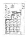
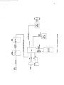
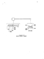
f o r ELOG setup. The €LOG system block diagram i s shown i n Figure 1.
.
The RCA microcomputer board i s based on t h e COP1805CE microprocessor [2, 31
which has been s e t up t o run FORTH (41, a h i gh-1 eve1 computer 1anguage.
A1 though s i m i l a r i n some respects t o BASIC, FORTH i s f a s t e r and more compact
than BASIC, features t h a t are o f prime concern f o r small systems 1i k e t h e
ELOG, A1 though assembly language i s f a s t e r than FORTH it i s n o t we1 1 suited
t o easy program modification, a necessary feature i n a dynamic research
s i t u a t i o n . The code (4k bytes) i s w r i t t e n i n a combination of FORTH and
assembly which can be c a l l ed from FORTH.
Timi ng i s provided by an Omega Radio synchronized clock which i s accurate t o
about 20msec. Omega i s a world-wide system run by t h e United States Coast
Guard p r i m a r i l y f o r navigation. 1t s transmissions, however, are very
precisely timed which a1 1ows the synchronization of a clock from the r a d i o
pulses. The p a r a l l e l time output o f the clock i s i n p u t t o the ELOG and read
whenever an event i s detected. The radio/clock combination i s a commercially
avai 1abl e product [lo].
The data are stored on magnetic tape cassettes o r solid-state mass storage.
Without waveform data, up t o 2000 events can be stored on a s i n g l e cassette
tape o r 3200 i n a prototype so1 i d - s t a t e mass storage. The 1a t e r option could
be expanded i n the p r i n t e d c i r c u i t board version from a minimum of 512k-bytes
t o 2M-bytes. For e i t h e r recording configuration, the €LOG w i l l run f o r an
e n t i r e year on f o u r 1000 ampere-hr batteries. During t h i s time the program
monitors incoming data f o r what might be an event. Parameters f o r events t h a t
pass a screening t o eliminate 1ow frequency a r r i v a l s and noise bursts are
c o l l ected i n mass storage.
The heart o f the program i s a sampling loop which c o n t i n u a l l y updates a long
term average (LTA) and a short term average (STA) o f the data. Each time
through the loop these averages are compared t o see i f the STA exceeds the LTA
by a factor o f three, I f so the 12 second event b u f f e r ( s t a r t i n g when the STA
i s exceeded and l a s t i n g 9 seconds) i s tested f o r frequency content, energy and
event impulsiveness. I f the t e s t s are passed, the event parameters are
w r i t t e n t o a temporary b u f f e r which holds 19 events. A f t e r t h e 19th event the
b u f f e r i s w r i t t e n out t o mass storage.
The stored data i s d e t a i l e d below w i t h the number o f hexidecimal characters i n
the output I n parenthesis
1) Clock Status(1)-indicates whether the clock i s properly synchroni xed t o
owla
2) Detection Time(l1)-The i n s t a n t when the STA reaches o r exceeds the LTA by a
factor o f three, expressed i n terms o f J u l i a n day, hour, minute, second and
hundredth o f a second
3 ) PCTR (2)- Onset Time-The i n s t a n t before detection time when the STA reaches
o r exceeds twice the LTA expressed as the number of samples p r i o r t o the
detection time
4) IMOT ( 4 ) - Onset Sample Value-The value o f the data p o i n t a t the onset time,
This a1 so gives the p o l a r i t y o f the f i r s t motion.
5 ) IMAX (2)- Maximum Sample-The absolute value o f the l a r g e s t amplitude during
the f i r s t ha1f-cycle.
6 ) TMXS ( 2 ) - Time U n t i l F i r s t Zero Crossing-The number o f samples t o the f i r s t
change o f p o l a r i t y measured from the onset time
7 ) N3LT ( 4 ) - Energy Level -The number of times during the f i r s t nlne seconds o f
the event t h a t the STA drop below twice the LTA. This provides i n f o m a t i o n on
the energy duration of the event,
8) LTA(21- The LTA value before the event.
background noise.
This gives a measure o f the
9 ) ECTR(4)- Number o f triggers.
10) NZRO(4)- Number of zero crossing during the f i r s t 9 seconds o f event.
The other sections o f t h i s r e p o r t w i l l examine the hardware and software i n
more d e t a i l . A l l references t o "screen numbers" r e f e r t o the RAM cassette
version o f the FORM program (Appendix 3). Screen numbers are FORTH's way o f
d i v i d i n g up a program i n t o smaller units. The other program versions are
Cassette Tape (Appendix 4) and RAM cassette w i t h wavefonn storage which i s
c u r r e n t l y under development. The basic elements o f a l l three programs are
very simf l a r .
2. PROGRAM ORGANIZATION
The €LOG program i s organized i n t o three conceptual parts, only one o f which
w i l l be executing a t any given time. The central r o u t i n e i s the sampl i n g loop
(screen 25) which d i g i t i r e s incoming data and places the values i n a c i r c u l a r
buffer. The STA and LTA are then updated ( screens 15, 16) and compared t o see
I f a threshold has been exceeded. A t t h i s p o i n t the sampling loop i s e i t h e r
executed again w i t h a new sample i f the threshold t e s t f a i l e d o r program
execution moves t o the v e r j f y phase i f the threshold was exceeded.
I n the v e r i f y phase events are screened t o minimize the recording of noise.
The screening involves running three t e s t s on the data i n t h e b u f f e r t o
detemfne which events t o save. Amplitude and frequency content must match
the type o f earthquake being searched f o r and an emergence t e s t screens out
d i s t a n t events, I f these three t e s t s are passed then the f i n a l recording
phase i s entered a t which time the data i s w r i t t e n t o a RAM parameter b u f f e r
which i s u l t i m a t e l y w r i t t e n t o mass storage.
The €LOG software i s w r i t t e n i n FORTH, a computer 1anguage which f i n d s tna j o r
appl i c a t i o n i n dedicated microcomputer-based control systems. FORTH i s a
threaded, interpretive, extensible 1anguage [S, 6, 71. The t e n "threaded"
has t o do w i t h the way FORTH code i s compiled. I n t r a d i t i o n a l compiled
languages source code i s translated i n t o machine language as a u n i t and can
only be executed as a u n i t . I n FORTH each "word" i s compiled separately and
can be executed e i t h e r by i t s e l f o r w i t h other FORTH words. When FORTH words
are executed individual l y , operation i s simi 1a r t o other i n t e r p r e t i v e
languages such as BASIC. When many words are combined and executed as a
whole, operation i s s i m i l a r t o the FORTRAN subroutine. Defining new words
from a1 ready defined words o r from assembly language gives FORTH i t s
extensi b i l f t y
.
FORTH uses two stacks f o r fnter-word conmunfcation and math. The stack
o r i e n t a t i o n o f FORTH makes the use o f reverse p o l i s h operations necessary even
though code becanes harder t o read. A l l math i s done i n f i x e d p o i n t as FORTH
does not support f l o a t i n g point.
Tape 110 and the termi nal i n t e r f a c e is accompl ished by c a l l s t o a u t i 1 it y
ROM(UT62) supplied by RCA. This ROM contains the usual u t i l i t y routines f o r
w r i t i n g t o tape, reading from tape, examining memory, etc. I n addition, one
UT62 r o u t i n e automatical l y sets the ELOG baud r a t e t o match t h a t o f the
terminal (up t o 1200 baud).
2.1 Data Sampling
The sampling r o u t i n e i s interrupt-driven by a counter i n t e r n a l t o the 1805
CPU. The counter i s preset t o an i n i t i a l value by the word ADPG ( screen 2)
which controls the sampling rate. Each time the counter goes through zero the
CPU i s interrupted and the data sampled. I n the case where a higher sampling
r a t e i s desired, the counter i s pre-set t o a lower value. I n p r a c t i c e the
sampling r a t e i s l i m i t e d t o 100 Hz o r l e s s by the CPU processing speed.
The sampling loop f i r s t selects t h e A-0 by o u t p u t t i n a code 30H( hex) which
conforms t o the RCA two-level 1/0 addressing scheme 81. This selection i s
necessary since there are several 1/0 devices connected t o the CPU. The A-D
i s hard-wired t o be selected by the 30H code. Then two OOH codes are output
next t o program the s i n g l e channel mode and data channel zero. These two
steps configure the A-D t o d i g i t i z e only on channel zero o f the eight-channel
A-0.
Sampl i n g is started as soon as the i n t e r r u p t handl e r address ' i s
A semaphore( ?RDY) is
1oaded( IADR) and the counter i n t e r r u p t i s enabl ed( CTEN )
used t o h a l t sampling loop execution u n t i l the next sample i s ready. The
i n t e r r u p t handl e r code i s presented i n Appendix 1, while Screens 2 and 15
contain the above words.
f
.
Once the new sample i s stored f n memory, the word NXT converts the 8 - b i t
o f f s e t binary code produced by t h e A-0 t o a 2 ' 5 complement 16-bi t code and
stores the val ue i n the v a r i a b l e YNEW. This val ue i s placed i n the c i r c u l a r
b u f f e r by the word PUTY. Then t h e STA and LTA are updated by the words SAVG
and LAVG respectively. I n order t o increase processing speed SAVG and LAVG
use d i visions and absolute vat ue operators w r i t t e n as assembly 1anguage FORTH
"code" words. Since FORTH does not support f l o a t i n g p o i n t math, the code word
d i v i s i o n s also p u t the remainder on the stack. Use o f the remainder by SAVG
and LAVG gives a more continuous LTA and STA.
F i n a l l y a f t e r the LTA and STA have been updated, t h e i r values are compared by
the word ?EVT. ? EVT checks each time around the loop t o see i f the STA i s
three o r more time the LTA. Ift h i s occurs, then the main sampl i n g loop i s
temporarily e x i t e d and the v e r i f y section o f the program i s entered.
2.2 V e r i f i c a t i o n o f Events
Because memory i s a 1i m i t e d resource the v e r i f i c a t i o n words attempt t o prevent
recording events t h a t are not earthquakes. Before any t e s t s are made however,
the word RDTM (screen 2) reads the clock and stores the time i n memory f o r
1a t e r recordi ng If the event is deemed r e a l Then the word TAIL col 1ects
another nine seconds o f post-event data i n the data buffer. TAIL (screen 22)
uses a s i m i l a r sampling loop t o the one described above w i t h two differences:
the LTA and STA are not updated and the 1805 counter i s r e - i n i ti a1 i r e d by ADPG
t o a large value t o 1t m i t sampling t o the 100 Hz rate.
.
Now t h a t the above two time c r i t i c a l tasks are done, v e r i f i c a t i o n s t a r t s .
F i r s t the energy o f the wave i s checked by AMPL. AMPL counts the number o f
times t h a t the STA i s l e s s than two times the LTA. Then FREQ counts the
number o f ,zero crossings and SRCH f i n d s the onset time. SRCH searches back i n
time f o r t h e p o i n t where the STA f a l l s t o two o r l e s s times the LTA. (Refer
t o screen 21-23). This p o i n t w i l l tend t o be e a r l y as the STA i s an average
and w i l l not inmediately f o l l o w the data. To compensate f o r t h i s , t h e search
i s done again using a shorter averaging time (FAVG) and going f o m a r d i n time
t o f i n d the s t a r t o f the event. Thus SRCH f i r s t looks back i n time through
the b u f f e r f o r the approximate onset, which tends t o be early, and then
forward i n time f o r the t r u e onset sample. This procedure prevents noise
spikes j u s t p r i o r t o the onset from being picked. Table 1 gives the
parameters used i n the search process as well as other ELOG parameters,
When SRCH f i n i s h e s executing, i t produces a variable value which i s a measure
o f the impul siveness of the event. For the f i n a l recording phase o f the
program t o be entered, the variables values produced by AMPL, FREQ, and SRCH
must be w i t h i n the bounds given i n Table 1. Thus an event must maintain a
c e r t a i n energy level*, have a t l e a s t a minimum number o f zero crossings, and
not be too emergent. Parameters f o r events t h a t pass these t e s t s are recorded.
2.3 Event Recording
Each time an event passes the three t e s t s i t i s recorded i n t h e parameter
buffer. The parameter b u f f e r holds 19 events which are w r i t t e n t o mass
storage as a group. Mass storage i s e i t h e r a low-cost cassette tape recorder
o r a solid-state Rlemory array.
The cassette tape control software uses features b u i l t i n t o MB4TH.
SAVE-BUFFERS causes t h e e n t i r e parameter b u f f e r contents t o be w r i t t e n t o
tape. The variable USE which contains the number o f the next buffer t o be
used i s incremented and an update b i t i n the b u f f e r i s set.
W i t h the RAMcassette, a memory l o c a t i o n counter i s used t o address the memory
array CTRH and CTRL increment the counter, ENB and D l SB a c t i v a t e and
deac t itfate the RAMS, MEMRD and MEWR s e l e c t the read o r w r i t e mode, and E->R
and R->E do the reading o r w r i t i n g through the CDP1851CE progrannnabl e I10 p o r t
t91. This port, l i k e the A-D, must f i r s t be selected and programed f o r the
desired configuration. For example, when i t i s desired t o w r i t e a byte t o the
RAMcassette, one p o r t i n t e r n a l t o the 1851 must be set up as an output port.
These words are located i n screens 3-6,
For e i t h e r recording medium the parameters stored are the same. F f r s t the
clock time which i s available i n p a r a l l e l format i s converted t o byte-serial
by the word RDTM. Each execution o f RDTM i n i t i a l izes the 1851 as ha1f i n p u t
and h a l f output. The output h a l f sends control bytes t o the time buffering
electronics t o control the order of reading through the i n p u t ha1f o f the
port. Then the word WRTM m v e s the time bytes t o the parameter b u f f e r ifthe
screening t e s t s described above are passed. A compete memory map which shows
the l o c a t i o n of a l l €LOG memory areas i s given i n Figure 2.
The word FRST uses the onset time found by SRCH i n the v e r i f i c a t i o n phase t o
f i n d the d i r e c t i o n o f f i r s t mtion(IM0T) and the maximum value sample during
the f i r s t ha1f cycle o f the event( IMAX)
SRCH a1 so counts the number o f
sample points from the t r i g g e r time t o the i n s t a n t when the STA i s two times
the LTA. This value i s stored i n the variable PCTR. PCTR i s used as an index
t o the c i r c u l a r b u f f e r f o r the onset i n s t a n t and i s w r i t t e n t o the parameter
buffer by the word WRVR. WRBY w r i t e s the bytes IMOT and IMAX t o the buffer.
FRST then counts t h e number o f sampl es t o t h e f i r s t zero crossing from the
onset and stores the value i n TMXS which i s also w r i t t e n t o the buffer. Then,
the number o f times the STA fa1 1s below twice the LTA during the event (N3LT)
.
* Ift h i s l e v e l varies w i t h the r a t e a t which events are recorded, an
automatic energy threshold adjustment can be achieved. This allows a
recording r a t e which w i l l j u s t f i l l the available mass storage without having
t o r e - v i s i t the s i t e t o adjust t h i s parameter. The FORTH words t h a t implement
t h i s f u n c t i o n are given i n Appendix 6.
TABLE 1
- €LOG SETUP PARAMETERS
SPS, Sampl i n g Rate, Samples Per Second
100
Energy Test, N3LT <
300
WIND, window on event a f t e r t r i g g e r
9s ec
Zero Crossing Test, NZRO >
45
BOT, lowest address o f data b u f f e r
6000H
LTRG, onset threshol d
2
NBUF, b u f f e r 1ength
2400 (bytes)
Emergence Test, < sampl e times
T r i gger threshol d
LTA averaging time(LAVG1
STA averaging time(SAVG)
FAVG f a s t averaging time
*
FFFF
I
1
HIGH MEMORY-
,
ELOG WRVEFORM BUFFER
6080
I
NOT USE0
_
_
-
-
-
-
e
TERM INRL INPUT
BUFFER
4F1f
TERMINRL OUTPUT
BUFFER
4EBE
t
4E3C
4838
_
4835 i
4834
482C
1-
NOT USED
CLOCK TIME
SCRATCH
SCRATCH
NOT USED
-
NOT USED
4835
4834
I
TRPE UPORTE FLRG
I
NOT USED
ELOG FORTH WORDS
I
I
PRE-DEFINED SYSTEM
FORTH WORDS
UT62 MONITOR
PROGRRH
8000
FIGURE 2
- MEMORY
ALLOCATION MRP
11
I
i s stored a1ong w i t h the LTA. F i n a l l y the number o f t r i g g e r s (ECTR) i s stored
and ifthe RAM cassette i s used w i t h wavefonn storage the index t o the t r i g g e r
time, YCTR, i s also stored.
Each event record w r i t t e n t o tape o r RAM cassette storage contains 36 bytes.
The format used i s presented i n Table 2 and the €LOG programs f o r the RAM
Cassette and magnetic tape are i n Appendices 3 and 4. Note t h a t i f the
waveform i s also stored then an e x t r a 4 bytes o f data are needed t o i n d i c a t e
the t r i g g e r sample i n the b u f f e r r e l a t i v e t o the b u f f e r beginning, BOT.
3. SYSTEM HARDWARE
ELOG hardware consists o f a card cage f o r the f i v e p r j n t e d c i r c u i t cards, an
Omega Radio receiver, a clock, and e i t h e r a cassette tape recorder o r a
RAMcassette. Figure 1 shows a block diagram o f the system. As can be seen,
the radio produces synchonizing pulses which keep the clock on time a f t e r i t
has been i n i t i a l l y set, The p a r a l l e l clock time i s then available through the
i n t e r f a c e card t o the CPU. The i n t e r f a c e card a1 so has amp1i f i e r and power
converter sections. Program memory i s divided between the CPU, Tape 110 and
Memory expansion cards. A discussion of the various cmponents follows.
3.1 CPU Card
The CPU card uses a CMOS 8 - b i t CDP1805CE microprocessor running from a 2MHz
c r y s t a l . I n s t r u c t i o n s need an average o f 16 clock cycles f o r execution
r e s u l t i n g i n a processing r a t e o f 125,000 i n s t r u c t i o n s per second. The card
also has a s e r i a l RS232 p o r t which i s used f o r t e m i n a l communication a t up t o
1200 baud while a para1l e l programabl e p o r t i s provided f o r byte
input/output. The p o r t i s programed v i a software i n s t r u c t i o n s which
deternine whether the sections are t o be used f o r input, output, o r
b i - d i r e c t i o n a l data flow. The €LOG only uses the f i r s t two options. The card
m o r y section has four 27C16 EPROMs which contain the FORTH compiler and
i n i t i a l dictionary, as well as f o u r k i l o b y t e s o f RAM, The external i n t e r r u p t
and p o l l i n g features are not used. A w i r i n g diagram o f the RS232 cable i s
given i n Appendlx 5.
3.2 A-D Converter
The A-0 converter card converts b i p o l a r analog data t o o f f s e t binary $ - b i t
ramp1es. The RCA scheme f o r addressing 110 modules necessitates having each
module respond t o a "group s e l e c t code
The code recognized by the A-D
during an OUTPUT 1 i n s t r u c t i o n i s 30H which i s p u t on the bus as data.
.
A f t e r selection the A-D must be programed f o r f i x e d d i g i t i z i n g from channel
0, the i n p u t channel
This i s simi 1a r t o the group select described above,
except t h a t OH i s used f o r data and two other output i n s t r u c t i o n s are used f o r
the progranmi ng
.
.
A f t e r a l l these preliminaries, the A-D i s ready t o d i g i t i z e i t s f i r s t sample,
A "INPUT 3' i n s t r u c t i o n i n i t i a t e s t h e conversion. The code ( i n machine
language) which hand1es the A-0, semaphore (discussed i n Sec .2.1), and 1805
counter f n t e r r u p t d l sabl i n g i s 1oaded by the word ILD (screen 19) and f s
executed once f o r each sample.
The A-0 produces o f f s e t binary code which d i f f e r s from 2 ' s complement by the
most s i g n i f i c a n t b i t . For 8 - b i t numbers, i f 80H i s subtracted from the o f f s e t
binary number, a 2 ' s complement number resul ts. Thi s number covers the range
o f i n p u t voltages from -I+2.5 volts. An expression which r e l a t e s i n p u t
vol tage t o counts i s :
TABLE 2
- ELOG DATA FORMAT
DATA DESCRIPTION
FIELD
WAVEFORM
NO WAVEFORM
1
1
clock status, O=OK
2-12
2-12
BCD t i m e - j u l i a n day, hr, min, sec, 1/10, 1/100 sec
13,14
13,14
(PCTR) sample time offset from t r i g g e r t o onset
15-18
15-18
( IMOT) pol a r i ty-sampl e val ue a t onset
19,20
19,20
(IMAX)
21,22
21, 22
(TMXS) sample times from onset t o f i r s t zero crossing
23-26
23-26
(N3LT) number o f times STA fa1 1s be1ow twice LTA
27,28
27,28
(LTA) l o n g term average
29-32
29-32
(ECTR) number o f t r i g g e r s
33-36
33-36
(NZRO) number o f zero crossing during wind
37-40
x
41-44
( ENTH
maximum sample during f i r s t ha1f c y c l e
energy thresh01 d
(YCTR) index t o t r i g g e r p o i n t i n b u f f e r
Note: I f wavefom storage i s selected then an additional 1200 bytes o f wavefom data
follows immediately a f t e r the header. The header information i s a1 so displayed on a
tenni nal ifone i s connected during t h e event.
input voltage ( v o l t s ) = counts
*
0.019532125
where counts i s a hexadecimal number and must be converted t o base 10 before
mu1t i p 1 i c a t i o n .
3.3 Memory Expansion Board
The 1805 CPU can address up t o 64k-bytes o f memory o f which 8k-bytes o f ROM
are on the CPU board along w i t h 4k-bytes o f RAM. Another 2k-bytes of ROM and
lk-byte o f RAM are on t h e Tape 1/0 board. This leaves about 50k-bytes open
f o r expansion o f ELOG speclf i c FORTH words. Due t o the compactness o f FORTH,
only 4k-bytes are needed f o r t h e e n t i r e ELOG program which i s i n two 27C16
2k-byte by 8 - b i t CMOS EPROMs.
3.4 Tape 1/0 Board
The Tape I / O board serves t h e purpose o f providing additional memory sockets
and i n t e r f a c i n g w i t h the cassette tape recorders. The memory he1d on t h i s
board i s the u t i l i t y ROM(RCA UT62) and the FORTH e d i t o r and assembler. A CPU
reset switch i s a1 so 1ocated on t h i s board. When switched between r e s e t and
run, a signal i s generated which causes the CPU t o execute the u t i l i t y prbgram
IUT62).
3.5 Interface Board
The Interface Board provides regulated power for the e n t i r e system, b u f f e r s
the para1l e l time i n p u t from the clock and conditions the sensory input.
Figure 3 displays the e l e c t r o n i c schematic ( i n two sectfons) f o r t h i s c i r c u i t .
3.51 Power Regul a t i on
One LM309 3-pi n vol tage regul a t o r provides +5 vol t s t o power the system
e l e c t r o n i c s except f o r the clock and r a d i o which have t h e i r own i n t e r n a l
batteries. The regulator i s capable o f supplying one ampere o f which 500mA i s
a v a i l abl e f o r external use. Another vol tage converter( ICL7660) produces
negative 5 v o l t s f o r use by t h e signal conditioning section.
3.52 Signal Conditioning and A m p l i f i c a t j o n
Signal conditioning consists o f a m p l i f i c a t i o n t o match t h e dynamic range o f
the A-D converter and f i l t e r i n g t o prevent signal a1 iasing. The i n p u t signal
from the L4 v e r t i c a l geophone i s applied t o a low noise d i f f e r e n t i a l ampl i f i e r
composed o f a matched p a i r o f transistors. The i n p u t impedance produces a
c r i t i c a l damping f a c t o r o f 0.7 w i t h t h e gain f i x e d a t 21.5. A potentiometer
allows zeroing out o f any o f f s e t . I n the c i r c u i t shown i n Figure 3, a c u t o f f
frequency o f 30Hz results. This c u t o f f i s mainly influenced by the f i l t e r i n g
a c t i o n o f C8/R10 and C7/R6. Amp1 i f i e r U21 gives sol i d - s t a t e swi tchable gain
control from a minimum o f 340 t o 44,000 i n increments o f 6dB. The maximum
allowable signal coming out of the ampl i f i e r i s 1i m i t e d t o +/-2.5 V by the A-0.
3.53 Time Buffering
1he i n t e r n a l b a t t e r i e s o f the c l ock are 3.6 vol t L i t h i um so c l ock logic 1evel s
need t o be converted t o 5-vol t CMOS. This i s accompl ished by an array o f RCA
CD40109BE CMOS-CMOS l e v e l converters w i t h three s t a t e outputs. Each CD40109
converts 4 b i t s o f clock data which i s i n p u t t o the CDP1851CE 110 p o r t when
the CD40109 output d r i v e r s are a c t i v a t e d by a high on the enable l i n e s , The
high 1 evel i s produced by the word RDTM which sequential l y reads two n i bbl es
of data i n t o the p o r t s t a r t i n g a t 1/100s seconds. The sequential reading i s
implemented by decoding the output bytes produced by RDTM w i t h two 4028
decimal decoders. (The decoders are also used t o control t h e RAMcassette by
i n p u t t i n g d i f f e r e n t control bytes t o the decoders.
The w i r i n g diagram f o r the clock-interface card cable i s g l ven i n Appendix 5.
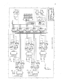
3.6 Mass Storage
The contents o f the parameter b u f f e r are dumped t o the mass storage device
every 19 events. E i t h e r a low c o s t cassette tape recorder, o r RAMcassette,
m y be used. The RAMcassette i s several times more expensive than the
cassette but can operate r e l i a b l y over a l a r g e r temperature range and hold
more data.
The RAMcassette consists o f an array o f 8k-byte by 8 - b i t CMOS RAM chips which
a l l sham the same address lines. A chip select signal determines which RAM
from the array i s active. This signal i s produced by a CD4516 CMOS 1 o f 16
decoder. The c i r c u i t diagram o f the 128k-byte version i s shown i n Figure 4.
The operation of the c i r c u i t i s f a i r l y s t r a i g h t fomard. F i v e hexadecimal
switches pre-load an address i n t o t h e 1 7 - b i t counter chain U27-U31 when the
reset button i s pushed. This address deternines where ( i n memory) array
r e a d l w r i t e operations w i l l s t a r t . B i t s 0 through 12 o f the counters are used
t o address each RAM memory l o c a t i o n while b i t s 13 through 16 are i n p u t t o the
decoder.
The counter i s software c o n t r o l l e d by the words CTRH and CTRL. Each execution
o f t h i s p a i r o f words advances t h e address by one count. The array i s
activated by the EN0 word which removes the i n h i b i t l e v e l from the decoder.
The read o r w r i t e mode i s selected by the words MEMRD and MEMWR. A1 1 these
signals f i r s t go through f l i p - f l o p s before they are applied t o any other
circuit.
Playback of the RAMcassette data i s handled by the word RDRECS which takes the
number of records desired t o be read o f f the stack. The data i s outputted
through the RS232 p o r t where i t can be transferred t o floppy disk by a
sui tab1 e t e m i nal program runni ng on a portabl e personal computer.
3.7 REAL TIME CLOCK
Real time i s supplied t o the ELOG through the i n t e r f a c e card by an Omega Radio
synchronized c1ock. Omega i s a worl d-wide, 1ow frequency, precisely timed
r a d i o signal whose s i x transmitters p u t o u t a r e p e t i t i o u s code. Decoding i s
done by the Omega Radio receiver which i s tuned t o the c h a r a c t e r i s t i c
frequency o f the nearest mega transmitter. The code i s used t o synchonize an
o s c i l l a t o r i n s i d e the receiver so t h a t the minute pulse output of the r a d i o i s
always w i t h i n 20msec o f i t s t h e o r e t i c a l value. This theoretical value i s
calculated by adding the o f f s e t between Omega (which uses Atomic Time), the
propagation delay due t o path length between the transmitter and receiver, and
the i n t e r n a l receiver delay
.
The delayed pulse output o f the r a d i o receiver i s i n p u t t o a clock whose time
runs ahead o f the radio pulses by the f i x e d amount calculated above. This
o f f s e t advance i s progrannned by three BCD switches. Once s e t correctly, the
delay i n the radio pulses i s cancel l e d by the advance i n the clock so t h a t the
clock runs w i t h i n 2Omsec of. real time. I f the recei ver i s unable t o decode
the i n e m f ng code, the pulse output's duty cycle i s changed thereby infowning
the clock o f a possible timing error. I n t h i s case t h e receiver o s c i l l u t o r
then free-runs on i t s own o s c i l l a t o r and the clock status b i t i s s e t t o 1.
4.0 OPERATIONS
Conducting any successful f i e 1 d experiment involves the c o r r e c t execution o f
many seemingly t r i v i a l tasks. D e t a i l s f o r an ELOG deployment include
selection o f b a t t e r i e s and Omega r a d i o receivers, the s e t t i n g o f the clock,
burying the sensor and s t a r t i n g t h e ELOG program. The information below i s
intended t o provide a guide f o r the deployment o f an array o f ELOGs. A w i r i n g
diagram i s given i n Figure 5 and the specifications i n Appendix 1.
4.1 Battery Considerations
A1 though there are many d i f f e r e n t types o f b a t t e r i e s avai 1abl e, t h e 6-vol t
rechargeable 1ead-aci d, o r the 2.5-vol t non-rechargeabl e a1k a l ine gel 1ed
e l e c t r o l y t e battery, probably are the most cost-effective choices f o r the ELOG
power source. Lead-aci d b a t t e r i e s are more sui tab1 e f o r dept oyments o f
several weeks, while a1 k a l i n e b a t t e r i e s can run an ELOG f o r one year b u t
cannot be reused.
The battery capacity needed t o run an experiment depends on the length o f the
experiment and the temperature. Capacity i s rated i n ampere-hours o r the
number o f hours o f battery l i f e a t one ampere. Since the ELOG draws l e s s than
0.1 ampere, the expected battery 1i f e i s ten times the amp-hr r a t i n g ,
expressed i n hours. O f t h i s only 80 percent should be used and t h i s number
must be f u r t h e r reduced i f operation be1ow freezing i s needed. The
manufacturer's data sheet w i l l contain the infonnation needed t o make an
economical choice.
4.2 Setting the Clock
Accurate and r e l i a b l e timing depends on a high signal-to-noise r a t i o o f the
Omega Radio signal. Thus t h e nearest Omega transmitter should be selected as
the frequency o f the (3mega r a d i o receiver. The antenna needs t o be placed
h o r i z o n t a l l y atop a pole so t h a t a 1ine drawn from the Omega transmitter t o
the s i t e makes a r i g h t angle w i t h the long axis o f the antenna. A button on
the receiver a c t i vates the LED so the incoming code pattern can be monitored.
I r r e g u l a r f l ashi ng means the antenna i s i n c o r r e c t l y oriented. When properly
oriented, the code consists o f two p a i r s o f pulses repeated every t e n seconds.
Since the code does not d i s t i n g u i s h between ten second i n t e r v a l s, t h e user
must provide the minute pulse by releasing the radio r e s e t switch a f t e r the
new minute. Thus a watch having an accuracy o f 5 seconds, o r a WWV r a d i o
receiver i s needed. The reset button i s released a t the end o f the f i r s t long
pause, of the receiver LED a f t e r the m i nute. The receiver w i l l then
automatically synchronize i t s output t o Omega a f t e r this. I f the button i s
released more than f i v e seconds a f t e r o r before the s t a r t o f the long pause,
the clock w i l l run an i n t e g r a l mu1t i p l e o f ten seconds from r e a l time.
The clock must now be set s t a r t i n g w i t h minutes and working up t o the J u l i a n
day. The receiver autolnatically takes care o f the seconds, so no seconds
switch i s provided. The delay mentioned i n section 3.7 must a1 so be set.
This delay i s the sum o f three components: the receiver delay, propagation
delay and atomic time o f f s e t from GMT. Table 3 contains p e r t i n e n t information
on the Omega transmitters which can be used t o compute the proper settings on
the clock. For example, i n Anchorage, Alaska the path length from the Hawaii
transmitter i s 4500km. Mu1t i p l y i n g t h i s number by 3.3 x lo**-6 y i e l d s a 15ms
propagation delay which i s added t o 4.81s f o r a t o t a l delay o f about 4.83ms.
Note t h a t the leap seconds o f t e n added a t the end o f June o r December cause
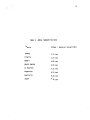
TABLE 3
- OMEGA TRANSMITTER DATA
Station
Offset
Noway
2.11 sec
Liberia
3.51 sec
Hawa ii
4.81 sec
North Dakota
5.91 sec
La Reunion
7.31 sec
Argentina
8.51 sec
Austral i a
9.61 sec
Japan
0.81 sec
+
Recel ver Del ay( 1/85)
GMT t o advance w i t h respect t o Atomic time by one second per year. Consult
the manufacturer's operation manual [lo] f o r more d e t a i l e d i n f o r m a t i on, I t
should a1 so be noted t h a t a l l Omega transmitters shut down f o r periodic
maintenance. The Hawaii transmitter, f o r example, i s maintained i n June.
exact dates can be ascertained by c a l l i n g the Hawaii Omega Transmitter,
808-235-4981.
The
Once the delay i s set v i a the three BCD switches on the clock f r o n t panel, the
clock w i l l approach r e a l time a t the r a t e o f 3msec per minute. Thus, i f the
i n i t i a l s e t t i n g were o f f by 3 seconds, i t would take about 17 hours f o r the
time t o f i n a l l y be accurate. During t h i s period, o r f o r any period o f poor
radio receptqon, the status b i t w i l l be high(1ogic 1). For good time t h e
status b i t w i l l be low ( l o g i c 01, I t can also be seen t h a t the time needed t o
"lock" onto real time can be g r e a t l y reduced by having a watch accurate t o
1 ess than +/- 5 seconds.
4.3 SENSOR INSTALLATION
The €LOG f r o n t end i s s e t up f o r the Mark Products L4 geophone. The sensor
should be buried as deeply as p r a c t i c a l a t l e a s t 50 f e e t from the r e s t o f the
s i t e . This w i l l help minimize noise coup1 i n g from the s i t e t o the geophone.
A l e v e l should a1 so be used t o achieve an o r i e n t a t i o n w i t h i n +/- 5 degrees t o
the v e r t i c a l axis t o the geophone axis.
4.4 ELOG setup-step by step
1. Bury the sensor as described above and connect t o "GEOPHONE" connector
input. Connect r e d geophone wSre t o white wire on geophone cable and black t o
b l ac k
2. Connect the RG-58 coaxial cab1e from the Omega receiver antenna t o "ANT"
input.
3. Synchronize the Omega receiver and set the clock as described above.
4. Connect the power cable t o "POWER".
5. Connect oscilloscope probe t o t e s t p o i n t s and a d j u s t gain on amp1 i f i e r
u n t i l signal i s 200-400 mv peak-to-peak.
Remove probe,
6. Connect one end o f the RS-232 cable t o "EIA" connector on CPU board and
the other end t o the TRS-80 model 100 computer runnf ng the terminal emu1 a t i o n
program a t 1200 baud.
7. Reset CPU switch on Tape 110 board, and type PQ. The ELOG w i l l respond
first w i t h an "*N and then a f t e r P0 i s typed w i t h the MB4TH we1come message.
Then type "HEX".
8. Type "XXXX EXECUTE" where XXXX i s a hexidecimal address given i n Appendix
3 or 4. I f cassette tape i s being used f o r storage, depress the rewind button
on t h e tape recorder. When the tape i s rewound, press any key and push down
the orange record button. I f t h e RAM cassette i s being used ignore the rewind
commands and depress any key.
9. V e r i f y t h a t the gain s e t t i n g i s c o r r e c t by tapping the ground several
times i n quick succession t o cause an event t o be recorded. (You w i l l a1 so
hear the terminal beep.) This should be done a t l e a s t twice a f t e r remaining
s t i l l f o r about 2 minutes. I f the LTA value sent t o the terminal i s not i n
the range o f 4-8 a d j u s t t h e gain switch accordingly.
10. Note the time on the clock, gain setting, LTA value and clock status.
The system i s now running.
.
REFERENCES
Microboard Revelopment Systems, RCA So1 id State D i v ,, Somervi11e,
New Jersey (1982)
User Manual f o r the COP1802 COSMAC Microprocesor, RCA S o l i d State Div.,
Somervill e, New Jersey ( 1976)
Microprocessors, Memori es, P e r i pheri a1 s, RCA Sol i d State D i v., Somervi 11e,
New Jersey (1982)
MB4TH, RCA So1 i d State Di v., Somervill e, New Jersey (1983)
Brody, L., S t a r t i n g Forth, 1981, Prentice H a l l
Loelinger, X., Threaded I n t e r p r e t i v e Languages
McCabe, K. C,, Forth Fundamental s, 1983, D i l it h i urn Press
User Manual for the RCA COSMAC Microprocesor Development System, RCA S o l i d
State Div., Somervill e, New Jersey ( 19811
Using the CDPl8Sl Programable I/O, RCA So1 i d State D i v . , Somerville, New
Jersey ( 19821.
Omegarec/Omegaface, Observatiore Cantonal , Neuchatel , S w i t z e r l and
25
Appendix 1
Specifications
ELOGIRAMcassette
ELOGICassette Tape
Maximum I n p u t (mV)
7.27/2**GAIN
7.27/2**GAIN
Current D r a i n (mA)
90
120
Supply Vol tage (Vol ts)
7.5-14
7.5-14
Operating Temperature
-20mc-50'~
O'C-50'~
Mass Storage Capacity*
128 K-bytes (prototype)
80K-bytes
Mass Storage Current Drains
< 1 ma
30 ma
Mass Storage Supply Voltage
5v ( f r o m €LOG)
6-7.5
A-D Resol u t i on
8 bits
8 bits
up t o 100
up t o 100
Size ( w i t h water t i g h t box)
12" x 12" x 22"
12" x 9" x 22"
Amp1 i f i e r ~ a i n '
340-44,000
340-44,000
A m p l i f i e r Noise ( a t i n p u t )
~ M oV r l e s s
I V Y o r Jess
Dynamic Range
48 dB
48dB
Desired LTA Val ue
5-9 counts
5-9 counts
Sampl i ng Rate
Cost (1984)
(SPS)
2500
v (ext. battery)
2000
*
1/2M-byte RAM cassette has been designed
+
Gain i s s e t d i g i t a l l y by amp1 i f i e r switch, w i t h lowest value 0 and highest 7
APPENDIX 2
ADDR
4688
4689
468A
4688
468C
4680
468E
468F
4690
4691
4692
4693
4694
4695
4696
4697
4698
4699
469F
4698
4691:
CODE
78
EO
F8
82
A0
F8
46
BO
F8
30
50
61
F8
-- INTERRUPT HANDLER
MEMON1C
SAV
0 SEX
LDI
0 PLO
LDI
0 PHI
LO1
STR
1Our
so
65
F8
ADOR
CODE
4690
469E
469F
46A0
46A1
46A2
46A3
46A4
46A5
46A6
46A7
46A8
46A9
46AA
46AB
09
AB
28
8B
3A
9F
6B
10
F8
01
operand
82->R(0) .0
operand
46->R(0) .1
operand
D->M(R(o) ,M(4682)=30
30->output ,R( 1)=4683; sel A-D
LDI
00
50
66
F8
00
COMMENT
T->M( R2 )
0->X
STR
6 OUT
LDI
STR
5 OUT
LDI
MEMOYIC
B PLO
0 OEC
B GLO
BNZ
( addr)
3 IMP
0 INC
LDI
operand
0->M(RO) ) ,M(4683) =0
0->output ,R( 1)=4684mfuxed ch.
operand
0->M(R(O) ,M(4684)=0
0->output,R( 1)=4686, se1 ch.0
COMMENT
operand
9->R( B ) .O
0-1->B
R(B) .O->D
short branch t o addr.
branch back t o addr
M(4685)=A-D sample byte
R(O) =4686
STR
2 SEX
C ID
operand
0->M(R(o), ~ ( 4 6 8 6 ) t l , ( semaphore)
2->X
disable counter i n t e r r u p t
RET
r e t u r n t o main program
"Appendix 3:
SCR# (1) '
-----
' ELOG EARTHPUAt::E RECORDER
1 VERSION: 3-14-86
2 V E R S I O N TYPE: RAMCASSETTE
3 HIGHEST SCR#: 26
0,.
4
RAM Cassette Software"
-----
EXECUTION ADDR: 2DOA
5
6
7
e
9
10
11
12
13
14
15
16
17
18
SCRI 1
O HEX 2000 DP ! ( TM BYTES 4F36-30)
1 CODE RDTM
2 36 LDI Q FLO 4F LDI O PHI
3 8 ID1 O STR O SEX 1 OUT O DEC
4 ( SELECT 1/0 PORT 1
S B LDI O STR 2 OUT O DEC ( A=INP)
6 53 LPI O STR 2 OUT 0 DEC ( E=OUT)
7 P L D I O STR 2 OUT 0 DEC
( INTB=(:l)
8
1 L D I O STR 2 OUT 0 DEC
( INTA=O)
9 ( READ TIME BYTES)
10 5 LDI O STR 6 OUT 0 DEC 4 INP O I N C
11 4 LDI O STR 6 OUT O DEC 4 INP O I N C
12 3 LDI O STR 6 OUT 0 DEC 4 INP O INC
13 2 LDI O STR 6 OUT O DEC 4 INP O INC
14 1 LDI O STR & OUT 0 DEE 4 INP O INC
15 O LDI O STR 6 OUT O DEC 4 INP O INC
16 9 SEF END-CODE
17 --)
IS
SCR# 2
O ( CODE DEFINITIONS) HEX
1 CODE ADPG ( PGRM 1805 CT 1
2 XID CID STPC 49 LDI LDC STM 9 SEP
3 END-CODE
4 CODE H I E ( SET MIE, ALLOW INTR
5 RET 9 SEP
6 END-CODE
7 CODE CTEN ( EN0 1803 CTR I NTR
8 CIE 9 SEP
9 END-CODE
10 CODE CTDS ( DISENP 1805 CTR INTR 1
11 C I D 9 SEP
12 END-CODE
13 CODE IADR
( INTR HANDLER ADDR 1
14 88 L O 1 1 PLO 46 LDI 1 PHI 9 SEP
15 END-CODE
--
16 CODE NRDY (
) ( DATA NOT RDY)
17 46 LDI O PHI 86 LDI O PLO O LDI
18 0 STR 9 SEP
END-CODE
-->
SCRH'3
.
Cr ('CODE-DEFINITIONS) HEX
1 CODE CTRH ( SET CTR F/F)
2 34 LDI O PLO 48 LDI 0 PHI 8 LDI
3 0 STR Q SEX 3 OUT 0 DEC ! SEL PORT)
4 53 LDI O STR 2 OUT O DEC ( B=OUT)
5 98 LDI O STR 6 OUT O DEC ( F/F=O)
SEP END-CODE
7 CODE CTRL ( CLEAR F I F )
8 54 LDI 0 PLO 48 LDI 0 PHI 8 LDI
9 O STR O SEX 1 OUT O DEC ( SEL PORT)
10 53 LDI O STR 2 OUT O DEC ( B=OUT)
1 1 99 LDI O STR 6 OUT 0 DEC ( F / F = l )
12 9 SEP END-CODE
6 9
13
14
--$
15
16
17
18
SCR# 4
O ( CODE DEFINITIONS) HEX
1 CODE MEMWR ( SET R/W tl€M TO WR)
2 34 LDI 0 PLO 48 LDI O PHI 8 LDI
3 O STR 0 SEX 1 OUT O DEC ( SEL PORT)
4 4E LDI O STR 2 OUT O DEC ( AoQUT)
5 53 LDI 0 STR 2 OUT O DEC ( B=OUT)
6 16 LDI O STR 6 OUT O DEC ( HEM RD)
7 9 SEP END-CODE
8 CODE MEMRD ( SET R/W = HI READ)
7 34 LDI O PLO 48 LDf O PHI 8 LDI
10 Q STR 0 SEX 1 OUT O DEC ( SEL PORT)
1 1 0 LDI O STR 2 OUT O DEC ( A=IN)
12 53 LDI O STR 2 OUT Q DEC ( F=OUT)
13 6 LDI O STR 6 OUT O DEC ( MEM RD)
14 9 SEP END-CODE
15
16
-->.
17
18
SCR# 5
(3
CODE
DEFINITIONS) HEX
1 CODE ENB ( ENABLE HEM BANK SELTORR)
2 54 LDI 0 PLO 40 LDI O PHI 0 LDI
S O STR O SEX 1 OUT O DEC ( SEL PORT)
4 53 LDI O STR 2 OUT O DEC ( b=OUT)
5 96 LDI O STR 6 OUT Q DEE ( ENR DECR)
6 9 SEP END-CODE
7 CODE DfSB ( DISABLE MEM BANK SEL)
8 34 LDI 0 PLO 4B LDI 0 PHI 8 LDI
9 O STR O SEX 1 OUT 0 DEC ( SEL PORT)
10 53 LDI 0 STR 2 OUT 0 DEC ( P=OUT)
1 1 97 LDI O STR 6 OUT O DEC ( ENB DECR)
12 9 SEP END-CODE
13 CODE SPFPTR ( IN11 BUF ADDR PTR)
14 36 L D I 1 PLO 48 LDI 1 PHI
13 9 SEP END-CODE
16 CODE SELPTR ( PTR TO HEM BYTE)
17 36 LDI 1 PLO 4% L D I 1 PHI 9 SEP
18 END-COPE -->
SC.R# 6 .
"0 , ( COBE DEFINITIONS) HEX
1 CODE E->R ( WR FROM ELOG TO RAM)
2 34 LDI 0 PLO 4B LDI 0 PHI 8 LDI
3 O STR O SEX 1 OUT 0 DEC ( SEL PORT1
4 40 LDI O STR 2 OUT 0 DEE ( A=OUT)
5 53 LDI O STR 2 OUT O DEC ( B=OUT)
6 1 RNX 1 INC ( LOAD PTR IN R Q )
7 0 SEX 4 OUT ( WRITE BYTE)
8
9
10
11
12
13
14
15
16
17
9 SEP END-CODE
COPE R->E ( WR FROM RAM TO EL061
34 LDI 6 PL0 40 LDI O PHI 8 LDI
O STR O SEX 1 OUT Q DEC ( SEL PORT)
B LDI 0 STR 2 OUT O DEC ( &=IN )
53 LPI O STR 2 OUT O DEE ( B=OUT)
1 RNX ( LD PTR TO RO)
O SEX 4 INP ( READ BYTE)
9 SEP END-CODE
-->
18
SCR# 7
0
1
2
3
4
S
6
7
8
9
10
11
12
13
14
15
16
17
---
CODE K /
( NUM
REM QUOT
HEX
PAGEJUMP I DIV STK NUM BY 4096 I
( RO=DIV'D
RF=QUOT RD=REM Rl=SGNCTR)
2 SEX O L D I 1 P L O XRX ( CLR SGNCTR)
0 RLXA 0 GHI SHL ( LD DIVPD,SGN->DF)
3 b C, 15 C, ( BNF POS ADDR...)
1 INC O GLO FF XRI 0 PLO O GHI
FF XRI O PHI O INC ( 2's CML LD SGN)
0 GHI (
POS ADDR
SHR SHR SHR SHR F PLO O LDI F PHI
O GLO D PLO 0 GHI 3 AN1 D PHI
1 GLO ( RO=REM, LD SGN CTR)
32 C, 39 C, ( BZ END ADDR...
1
F GLO FF X R I F PLO F GHI FF XRI
F PHI F INC ( 2 ' s COMPL)
D GLO FF KRI D P L O D GHI FF XRI
D PHI D INC ( 2's COMPLI
2 DEC (
END ADDR
D RSXD F RSXD 9 SEP END-CODE -->
...
...
18
SCR# 8
O
CODE N/
(
DIVIDE BY 16-NIBBLE)
1 2 SEX O LDI 1 PLO IRX O R L X A
2
3
4
5
6
7
8
9
10
11
12
13
14
15
16
17
18
0 GHI SHL
3E C, 59 C,
(
PNF POS ADDR...)
1 INC O GLO FF X R I O PLO O GHI
FF XRI 0 PHI Q INC
O GHI (
POS ADDR
SHR F PHI O OLO SHRC F PLO
F GHI SHR F PHI F OLO SHRC F PLO
F GHI SHR F PHI F GLO SHRC F PLO
F GHI SHR F PHI F GLO SHRC F PLO
0 LDI D PHI O i3LO F A N 1 D PLO
1 GLO
32 C, 8D C, ( BZ END ADDR...)
F GLO FF XRI F PLO F GHI FF XRI
...
F PHI
-->
F
INC
..
71
LOO
-Im
X
urn
.
VARIABLES)
SCR# 12
D
('
HEX
1 VARIARLE N 3 L T ( # SAMPL < 3SLTG)
2 VARIABLE NZRO ( # 0 - X I N 5 SEC)
3 VARIABLE TLTA ( TEMP LOC L T A )
4 VARIARLE TYCTR ( TEMP LOC YCTR)
5 6000 CONSTANT ROT ( BUF START GDDR)
6 64 CONSTANT SPS ( SAMPLE RATE)
7 9 CONSTANT WIND ( TEST WINDOW,SEC)
8 2 CONSTANT LTRG ( ONSET THRESHOLD)
9 960 CONSTANT NPUF ( HEX BUFFER SIZE)
10 -->
11
12
13
14
15
16
17
18
SCR# 13
O ( €LOG WORDS
HEX
1 : FAVG YNEW 3 ABS STA a
4 /MOD
2
STA + ! RSTA + !
3
RSTA @ 4 /MOD STA + ! RSTA !
4
1 S T 4 3 MAX S f A ! ;
5 : YINC (
( INCR YCTR BY 2 )
6
2 YCTR + ! YCTR a NBUF > IF
7
O YCTR ! THEN ;
8 : YDEC (
) ( DECR YCTR BY 2 )
9
-2 YCTR + ! YCTR 3 O < I F
10
NPUF YCTR ! THEN ;
11 : SVEUF (
)
( BUF->RAM)
12 CTRL MEMWR ENB SEFPTR
13
24 O DO ( WH 40 BYTES->RAM)
14
E-)R CTRH CTRL
15 LOOP DISE ;
16 -->
17
18
SCR# 14
O ( ELOG WORDS) HEX
1 : RDCHAR (
1 ( RAM-SELOG)
2 CTRL MEMRD ENP SELPTR
3 R->E CTRH CTRL D I S P ;
4 : RDREC (
)
( REC->RS232)
s 24 ct DQ RDCHAR 4036 ca LOOP CR ;
6 : RDRECS ( N
( N RECS-TRS232)
7
0 DO RDREC LOOP ;
-
--
--
--
--
--
--
8 -:>
9
10
11
12
13
14
15
16
17
18
.
SCRm
o'
13 .
ELOE WORDS 1 HEX
1
1 t ?RDY (
2
4686 C3 ( WAIT NEW SAMPLE 1
3
REGIN DROP 4686 C3 UNTIL SP! :
1 ( REMOVE MEAN )
4 : NXT (
5
YNEW 3 YOLD !
6
4683 C3 80
YNEW ! ; ( 2's COMFL)
7 : PUTY YNEW a YCTR a aor + !
8
YCTRYINCF;
9 : SAVG
YNEW 3 ABV STA 3
N/
10
ST4 + ! RSTA + !
11
RSTA @
N/
STA +! RSTA ! ;
12 - - 3
--
(.
--
-
-
13
14
15
16
17
18
SCH# 16
O ( €LOG WORDS
)
HEX
-
1 : LAVG YNEW 3 ARV LTA 3
2
K/
LTA +! RLTA + !
3
RLTA 3
K/
LTA + ! RLTA ! ;
4 : KEEP I
4 SAVE YCTR,LTA,STA)
S
LTA 3 TLTA ! STA @ TSTA !
6
YCTR 3 TYCTR ! RSTA 3 TRSTA ! ;
7 : RSTR (
1 ( RESTORE 3 VAR)
8
TLTA @ LTA ! TSTA @ STA !
9
TYCTR a YCTR ! TRSTA a RSTA ! ;
-
--
10
11
12
13
--$
14
15
16
17
18
SCR# 17
( I N I T I A L I Z 4 T I O N S ) HEX
1 : INIT (
( INITIALIZE VAR)
2
97 USE ! ( WRITE-->SCR#37)
3
8096 4834 ! ( BO=UPDATE, 96+SCR#)
4
O YNEW ! 0 YOLD ! 0 YCTR !
5
1 STA ! 10 LTA ! 1 TSTG !
6
0 RSTA ! O RLTA ! 0 PCTR !
7
OIMAX ! O I M O T ! O T M X S !
8
4836 OPTR ! 4B36 TPTR !
9
4687 IPTR ! O NSLT ! F NZRO !
10
1 TLTG ! 1 TYCTR !
11
O ECTR ! ;
12 --4
13
14
13
0
16
17
18
--
SCR# 18
WORDS > HEX
1 r FRST (
1 ( FIRST MOTION)
2
1 IMAX ! 1 I M O T ! 0 THXS ! KEEP
3
PCTR 3 ABS Q DO YDEC LOOP
4
YCTR a POT + 3 IMOT ! ( a LTRG 1
S
BEGIN ( LOOK FOR MAX & N I N )
6
I M O T 3 YCTR @ ROT + @ XOR 0)
7
IMOT a YCTR a POT + a = OK
@ '(. €LOG
8
9
10
11
12
13
--
WHILE
YCTR 3 POT
-->
+ 3 RPS 1MkX 3
HCIX I M A X !
TMXS l + !
YINC
REPEAT RSTR ;
14
15
16
17
18
SCR# 19
O ( ELCG WORDS) HEX
1 : WRBY ( ADDR
DUF
2 1 + C3 2 / 2 / 2/ 2 / OF AND
3
OPTR @ C ! OPTR I + !
4
1 + C@ O F AND
5 OPTR 3 C ! OPTR l+!
;
6 : >> ( BYTE
( I N T R LOADER)
7 I P T R l+! IPTR 3 C! :
8 : ILD (
) ( INTR:4688-46EE1
9 78 $ 3 €0
Fa $ 4 82 )>
3.>
10 F8 :;.> 46 >>.
>> F8 >> 30 32
11 50 ?> 61 :>> F8 >> 00 > $ 50 > 3
12 6& ).> F8 r.3. 00 >.> 50 >:> 6 5 >>
13 F8 3). 09 >> FIB >> ZB >> 8P >>
14 3 A >> 9F >> bE >> 10 >> F8 >>
15 01 >> 50 >> EZ >> b8 >> OD >>*
16 70 >> ;
17 --).
18
SCR# 20
0 ( ELOG
WORDS ) HEX
1 : WRVR ( ADDR
) DUP DUF' DUF'
2
2 O DO ( WR 4 BYTES-->BUFFER
-?
4
I + C3 2 / 2/ 2 / 2/ O F AND
4
OPTR @ C ! OPTR l+!
5
I + C@ O F AND
6
OPTR 3 C ! OPTR
l+!
7
LOOP ;
8 : WRTM (
1
9
6 O DO ( 1 1 T I M E , l STATUS -->FUF
10
TPTR @ C3 O F AND
11
OPTR a c ! OPTR
I+!
12
TPTR 3 C@ 2/ 2/ 2 / 2 / O F AND
13
OPTR 3 C ! OPTR l + ! TPTR l + !
14 LOOP ;
15 -->
16
17
18
--
--
-%
>: .
--
--
8
SCR# 21
b ( E L 0 8 WORDS HEX
1 : SRCH (
( F I N D LOTHRSH TIME)
2 O PCTR ! KEEP ( I N I T I A L I Z E )
3
NEUF 4 / O DO
4
YCTR 3 POT + @ YNEW ! SAVE
5
STA 3 LTA 3 LTRG
<
6
STA 3 LTQ 3 LTRG t = OR I F
7
L E A V E THEN
8
PCTR l + ! YDEC
9
L O O F LTA 3 STA ! 0 RSTA ! ( REST STA)
10 40 O DO ( LOOK BACK FOR START)
11 YCTR 3 ROT + @ YNEW ! FAVG
12 ST4 3 LTA 3 LTRG $ > I F
13
LEAVE THEN -1 PCTR + ! YINC
1 4 L O O P RSTR ; -->
15
16
17
18
SCR# 22
O ( ELOG WORDS) HEX
l : T Q I L (
1 ( SSEC POST E V )
2
KEEP ( SAVE YCTR,STA,LTA)
3
ADPG CTEN ( START CTR, ENR I N T R )
4
SFS WIND d 0 DO
5
IADR CTEN ?RDY ADPG
6
NRDY NXT PUTY LOOP RSTR ;
7 : AMFSL (
( DURATION CHECK)
8
KEEP 0 NJLT !
9
SPS WIND f O DO
10
YINC
11
Ei3T YCTR @ + 3 YNEW ! SAVG
12
STA @ LTA 3 2 $ < I F
13
N3LT I + ! THEN
14
LOOP RSTR ; ( N3LT=#VIOLATIONS)
15
16
--
*
'
--
--
-->a
17
18
SCR# 23
O ( €LOG WORDS 1 HEX
1 : FREB (
1 ( CK #a-X I N 5 SEC)
2 0 NZRO ! KEEP ( RESET O-X C T R )
3 SPS WIND $ O DO YINC
4 ROT YCTR 3 4 3 ( 1ST POINT)
5 ROT YCTR 3 2 + + 8 ( 2ND FOINT)
6 XOR 04: IF ( SEE I F SIGN CHANGE)
7 NZRO l + ! THEN
8 LOOP RSTR ;
--
9
10
11
12
13
14
15
16
17
18
-->
SCR# 24
0' ( ELOG WORDS
HEX
"1 5 DOLT (
1 ( OUTPUT DATA)
2 WRTM YDEC FRST PCTR WREY IMOT WRVR
3
I M A X WRBY TMXS WRFY NSLT WRVR LTA
4 WREY ECTR WRVR NZRO WRVR
5 4B36 TPTR ! 4836 OPTR ! SVPUF
&
6 b DO 4036 I + C@ OF AND
7
2 t 2 t 2* 2 6
8
4836 I + C3 F O AND 2/ Z/ 2 / 2 / +
9
LOOF' CR
1O
P C T R I M O T I M A X TMXS N3LT L f A ECT
11 R NZRO" CR SPACE
12 PCTR ? 2 SPACES IHOT ? 2 SPACES
13 I M A X ? 3 SPACES THXS ? 2 SPACES
14 N3LT ? SPACE LTA ? 4 SPACES
15 ECTR ? SPfiCE NZRO 3 CR ;
16 --:S
17
18
SCR# 25
a r ELOG WORDS HEX
1 : ?EVT (
( CHECK FOR TRIG)
2 S f 0 3 LTA 3 3*
1 IF
3 RDTM FELL T A I L ( GET TIME F I R S T )
4
ECTR 1+ ! ( COUNT EACH BEEP)
5 AMPL FRED SRCH ( VALID. CHECK)
6 N 3 L T 3 B4
< ( ENERGY)
7 NZRO @ 13
> ( FREQ. TEST)
8 PCTH 3 1 2 C
4 ( IMPL. TEST)
9 AND AND I 3 CONDITIONS TRUE?)
10 I F DOUT THEN STA 3 LTA ! THEN :
11 -->
12
13
14
15
16
17
18
SCR# 26
O ( ELOG WORDS) HEX
1 : RUN (
1 ( RUN PROG)
2 STAPES I N I T I L D CTDS HIE I A D H ADPG
3 BEGIN
4
I A D R CTEN ?RDY NRDY NXT PUTY SAVG
S
IADH CTEN ?RDY NRDY NXT PUTY LAVG
6
I A D R C T E N ?RDY NRDY NXT PUTY
7 1 L T A B MAX LTA ! ?EVT
8 0 UNTIL ;
--
."
--
*
--
9
10
11
12
13
14
15
16
17
18
SCR# 27
C)
.
"Appendix 4 :
___--
C
.
ELOG EARTHQUAKE RECORDER
1 VERSION DATE: 3-14-86
2 VERSION TYPE: CASSETTE TAPE
3 HIGHEST SCRt: 21
4 EXECUTION ADDR: 2FA6
Cassette Tape Software"
-----
5
6
7
8
9
10
11
12
13
14
15
16
17
18
SCR# 1
DP ! ( T H BYTES 4R36-3E)
1 CODE RDTM
2 36 LDI O FLO 4F LDI 0 PHI
3 8 LDI O STR 0 SEX 1 OUT O DEC
Q HEX 2000
4
(
SELECT 1/0 PORT 1
5 R LDI Cl STR 2 OUT O DEC ( A=INP)
6 53 LPI O STR 2 OUT 0 DEC ( F=OUT)
7 9 LDI CI STH 2 OUT O DEC
( INTB=O)
8 1 LDI O STR 2 OUT O DEE
( INTA=O)
9 ( READ TIME BYTES)
IQ 5 LDI O STR 6 OUT O DEC 4 INF O INC
1 1 4 LDI Q STR 6 OUT O DEC 4 INP O INC
12 3 LDI 0 STR 6 OUT 0 DEC 4 INP O INC
13 2 LPI O STR 6 OUT 0 DEC 4 INP O INC
14 1 LDI O STR 6 OUT Q DEC 4 INF' O INC
15 O LDI Q STR 6 OUT O DEC 4 INP Q INC
16 9 SEP
17
-->
END-CODE
18
SCR# 2
( CODE DEFINITIONS) HEX
CODE ADPG ( PGRM 1805 CT )
XID CID STPC 49 LDI LDC STN 9 SEP
END-CODE
CODE MIE ( SET MIE, ALLOW INTR )
5 RET 9 SEP
6 END-CODE
7 COPE CTEN ( ENP 1805 CTR INTR )
8 CIE 9 SEP
9 END-CODE
10 CODE CTDS ( DISENE 1805 CTR INTR
1 1 CID 9 SEP
12 END-CODE
13 CODE IADR ( INTR HANDLER ADDR )
14 88 LDI 1 PLO 46 LDI 1 PHI 7 SEF
O
1
2
3
4
15 END-CODE
--
14 CODE NRDY (
)
( DATA NOT RDY)
17 46 LDI O P H I 86 LDI 0 PLO 0 LDI
l R 0 STR 9 SEP END-CODE -->
.
scp#,3
.
,
--
0 CODE I?/
1 PAGEJUMP
2
3
4
5
6
7
8
9
10
11
12
13
14
(
..
,
'
NUM
(
.
---
REM QUOT
HEX
DIV STK NUM BY 4096
( RO=D1VFD RFaQUOT RDaREM RlsSGNCTR)
2 SEX Q LDI 1 PLO I R X ( CLR SGNCTR)
Q RLX4 0 GHI SHL ( LD DIV'D,SGN-TDF>
30 C, 15 C, ( BNF POS ADDR...)
3 INC O GLD FF XRI 0 PLO 0 GHI
FF XRI O PHI O INC ( Z ' S CML LD SGN)
Q GHI (
POS ADDR 1
SHR SHR SHR SHR F PLO O LDI F PHI
0 GLO D PLO 0 GHI 3 AN1 D P H I
1 GLO ( ROrREH, LD SGN C f R )
32 C, 39 C, ( BZ END ADbR
)
F GLO FF XRI F PLO F GHI FF XRI
F PHI F INC ( 2 ' s COMPL)
...
...
15 D GLO FF XRI D PLO D G H I FF X R I
16 D P H I D I N C ( 2 " s COMPL)
17 2 DEC (
END ADDR 1
18 D RSXD F RSXD 9 SEP END-CODE -->
...
SCR# 4
( DIVIDE BY 16-NIBBLE)
1 2 SEX O LDI 1 PLO IRX O RLXA
2 O GHI SHL
3 3P C, 59 C, ( PNF POS ADDR...)
4 1 INC 0 GLO FF XRI C) PLO O GHI
3 FF X R I Q P H I 0 INC
6 O GHI (
POS ADDR
7
SHR F P H I O GLO SHRC F FLO
8 F GHI SHR F PHI F GLO SHRC F PLO
9 F GHI SHR F PHI F GLO SHRC F FLO
0 CODE N/
...
10 F G H I
11 O LPI
12 1 GLO
13 32 C,
14 F GLO
15 F PHI
16 -->
17
18
SCR# S
0
1
2
3
4
5
SHR F PHI F GLO SHRC F PLO
D P H I Q GLO F AN1 D PLO
8D C p
(
BZ END ADDR...)
FF X R I F PLO F GHI FF
F INC
XRI
D GLO FF XRI D PLO D GHI FF X R I
D P H I D INC
2 DEC (
END ADDR)
D RSXD F RSXD
...
9 SEP END-CODE
CODE AEV ( NUM
6 PAGEJUMP 2 SEX
-- APSNUM
IRX
O
HEX
RLXA
7 O GHI 80 AN1
8 32 C, 12 C,
9 O G H I FF X R I O PHI
10 0 GLO FF X R I O PLO
11 0 I N C 2 DEC O RSXD
12
9 SEP END-CODE
13 CODE 3 t ( NUM
14 2 SEX I R X IRX
15 O
16 END-CODE
17
18
--
PROD)
(
POS 'BYTE)
LDX SHL 4DC STXD
LDI O ADCI STXD 9 SEP
-->
#
CCCCccccccc cc
~ C C C C - I < < < €
JDDVO
m I D D D D DDDDDDDDDDD DD
""""Z YJA"3J n x R A n X r n
g~~~~~
u u w u
-
E2$
Dn
DDPDDDDDDDDDDDDD
m0mmtlllm'mmmmmmmmmmmmmmmw
r
r
-D
r
r
r
r
r
r
r
o r r r r ~ rrrrrrrr
DDDDR
zmrnrnmm
tn
r
-I -I -I z z PI
mmmmm m m m mmmmmmmm m p
m++r
z n - 1 3 ~ ~ -
4rn-r~
n-lD
D
D<TNG.I#
-I-4DO-I
rn
o
4
-
3
---m
-I*#
-4 m
-PIXOLn
=I3 I P
I
h
x
r n ~x x
c r w
v
r ~ w
0 0 2
too
2%
-I
ro1
D<-l
Irl
BODU)*
-~+-mr
R
BY
u
0-1
-D
Y
0ZLn-l
If
- x rz
A
-1
40
-I3763
R 'I!
r
r -1
Zrom
~
O
-0
O Z
3
'II
-OD
OD<
3
GI
tn
a -i
-
mD
-I
4
.
SCR# 9
b '( ELCG WORDS
HEX
1 : FAVG YNEW @ ABS STA @
-
4 /MOD
STA + ! RSTA + !
3
RSTA @ 4 /MOD STA + ! RSTA !
4
1 ST& @ MAX STA ! ;
5 : YINC (
( I N C R YCTR BY 2 )
6
2 YCTR + ! YCTR @ NPUF > IF
7
O YCTR ! THEN ;
8 : YDEC I
( DECR YCTR BY 2 )
9
-2 YCTR + ! YCTR a o < IF
10
NBUF YCTR ! THEN ;
11 -->
12
13
14
13
16
17
18
2
--
--
SCR# 1 0
( ELOG
WORDS ) HEX
1 : ?RDY (
1
2
4686 C@ ( W A I T NEW SAMPLE )
5
BEGIN DROP 4686 C3 U N T I L S F ! :
( REMOVE MEAN )
4 : NXT (
5
YNEW 3 YOLD !
6
4685 C3 80
YNEW ! ; ( 2's COMPL)
7 : FUTY YNEW a YCTR a FOT + !
8
YCTR Y I N C F 9
9 : SAVG
YNEW @ AEV STA @
N/
10
ST4 4! RSTA + !
11
RSTA @
N/
STA + ! RSTA ! ;
12 -->
13
14
15
.
O
--
--
-
-
16
17
18
SCR# 11
O ( €LOG WORDS
HEX
1 : LAVG YNEW a ABV LTA 3
2
K/
L T A + ! RLTA+!
3
RLTA @
K/
L T A + ! RLTA ! ;
4 : KEEP (
) ( SAVE YCTR, LTA, STA)
S
LTA @ T L T A ! STA @ T S T 4 !
6
RSTA 3 TRSTA ! YCTR 3 TYCTR ! :
7 : RSTR (
( RESTORE 5 VAR)
8
T L T A 3 LTA ! TSTA 3 STA !
9
TRSTA @ RSTA ! TYCTR 3 YCTR ! ;
10 -->
-
-
--
11
12
13
14
15
16
17
18
SCR#
12 '
"C, ; INIrTIALIZATIONS) HEX
--
1 : INIT (
( INITIALIZE VAR)
97 USE ! ( WRITE--SSCR#97)
3
8096 4834 ! ( 80=UPDATE, 96=SCH#)
4
0 YNEW ! O YOLD ! Q YCTR !
5
1 STA ! 10 LTA ! 1 TSTA !
6
O RSTA ! O RLTA ! 0 PCTR !
7
0 IMAX ! O I M O T ! O TMXS !
8
4836 OPTR ! 4B36 TPTR !
9
4687 IPTR ! Q N3LT ! F NZRO !
10
1 TLTA ! 1 TYCTR !
11
O ECTR ! ;
2
12 -->
13
14
15
16
17
18
SCR# 13
0 ( ELOG WORDS
HEX
1 : FRST (
) ( FIRST MOTION)
2
1 I M A X ! 1 I M O T ! O TMXS ! KEEP
3
PCTR 8 4ES O DO YDEC LOOP
4
YCTR @ BOT + 3 IHOT ! ( @ LTRG )
5
BEGIN ( LOOK FOR MAX & H I N )
6
IMOT 3 YCTR @ ROT + 3 XOR 0:.
7
IMOT 3 YCTR a BOT + 3 = OR
8
WHILE
9
YCTR 3 EOT + @ ABS IMAX @
10
MAX I M A X !
11
TMXS 1 + ! YINC
12
REPEAT RSTW ;
13 --' .>
14
15
16
17
18
SCR# 14
0 ( €LOG WORDS) HEX
1 : WRBY ( ADDR
) DUP
2 1 + C3 2 / 2/ 2/ 2 / OF AND
3 30 + OPTR @ C ! OPTR 1+ !
4 1 + C3 O F AND 30 +
5 OFTR @ C ! OPTR l+! ;
& : .)> ( BYTE
1 ( I NTR LOADER)
--
--
--
7 IPTR I + ! IPTR a c ! ;
8 e ILD (
) ( INTR:4688-46PE>
9 78 >> EO 3 ) F8 >> 82 >> A 0 >>
1 0 FH 2 ) 4 6 >> 00 >) FB > 4 30 >>
11 50 >> 61 >> F8 >> 00 >> 50 >>
12 66 >> F8 >> 00 >> 50 >> 65 >>
13 F8 >> 09 >> AB ? > 20 >> 8 B 22.
14 3 A )>. 9 F > 3 6 B >> 10 >> F8 >>
15 01 > 3 50 $> E2 2 ) 68 >> OD >>
16 70 31. ;
--
17 --$
18
Y
SERY 15'
O ( €LUG
WORDS ) HEX
1 : WRVR ( 4DDR
) DUP DUP DUP
2
2 0 DO ( WR 4 BYTES-->BUFFER )
3
I + C3 2 / 2 / 2 / 2 / OF AND
4
30 + OPTR @ C ! OPTR l+!
C
J
I + C 3 OF AND 30 +
6
OPTR @ C ! OPTR l+!
7
LOOF ;
)
8 : WRTM (
9
6 O DO ( 11 TIME,1 STATUS -->BUF
1
10
TFTR @ C3 OF AND
11
30 + OPTR @ C ! OPTR
l+!
12
TPTR a ca 21 21 21
OF ~ N D
13
30 + OPTR 3 C ! OPTR l+!
TPTR l + !
1 4 LOOP ;
15 --3.
--
--
z/
16
17
10
SCR# 16
O ( ELOG WORDS ) HEX
1 a SRCH (
)
( F I N D LOTHRSH T I M E )
2 O PCTR ! KEEP ( I N I T I A L I Z E )
3
NEUF 4 / O DO
4
YCTR @ POT + @ YNEW ! SAVG
5
STA @ LTA @ LTRG d <
6
STA 3 LTA 3 LTRG
= OR I F
7
LEAVE THEN
8
PCTR l+!
YDEC
9
LOOP
10 LTA 3 STA ! O RSTA ! ( RESET STA)
11 40 O DO ( LQOK BACK FOR START)
12 YCTR 3 FOT + @ YNEW ! FAVG
13 STA 3 L T A 3 LTRG
> IF
14
LEAVE THEN -1 PCTR + ! Y I N C
15 LOOP RSTR ;
>
--
*
--
16
17
18
SCR# 17
0 ( ELOG WORDS) HEX
1 : T A I L (
( SSEC POST EV)
2
KEEP ( S4VE YCTR, STA,LTA)
3
ADPG CTEN ( START CTR, ENF I N T R )
4
SFS WIND f 0 DO
5
IADR CTEN ?RDY ADPI3
6
NRDY NXT PUTY LOOP RSTR ;
7 : ANF'L (
)
( DURATION CHECK)
8
KEEP O N 3 L T !
9
SF'S WIND t 0 DO
10
YINC
11
ROT YCTR @ + 3 YNEW ! SAVG
12
STA @ LTA @ 2 $ q: I F
13
N3LT l+!
THEN
14
LOOP RSTR ; ( N3LT=#VIOLATIONS)
15 -->
16
17
--
--
18
--
scen la
( ELOS WORDS 1 HEX
1 : FRED (
1 ( CK #O-X I N S SEC)
2 O NZRO ! KEEP ( RESET 0 - X CTR)
3 SFS WIND $ O DO YINC
4 POT YCTR 3 + 3 ( 1ST POINT)
5 EOT YCTR 3 2 + + @ ( 2ND POINT)
6 XOR O< IF ( SEE IF SIGN CHANGE)
7 NZRO I + ! THEN
8 LOOP RSTR ;
O
9
--
--)
10
11
12
13
14
15
16
17
18
SCR# 1 4
O ( ELOG WORDS 1 HEX
1 : DOUT (
( OUTPUT DATA)
2 WATM YDEC FRST PCTR WRFY I M O T WRVR
3 INAX WRPY TNXS WRFY N3LT WRVR LTA
4 WRFY ECTR WRVR NZRO WRVR
S 4 OFTR + ! 4BS6 TPTR ! OPTR 3 4B2C >
6
I F SAVE-BUFFERS 4836 OFTR !
7
80 4834 C ! 4835 C3 1 + 4835 C !
8
USE I + ! THEN
9
6 O DO 4B36 I + C3 OF AND
10
2 X 2$ 2 s 2*
11
4R36 I + C3 F O AND 2 / 2/ 2 / 2 / +
12
LOOP CR
13
PCTR I M O T IMAX TMXS N5LT LTA ECT
14 R NZRO" CR SPACE
15 PCTR ? 2 SPACES IMOT ? 2 SPACES
16 IMAX ? 3 SPACES TMXS ? 2 SPACES
17 N3LT ? SPQCE LTb ? 4 SPACES
18 ECTR ? SPACE NZRO ? CR ; -->
SCR# 20
0 ( ELOG WORDS
HEX
1 : ?EVT (
) ( CHECK FOR TRIG)
2 ST4 3 LTA 3 J S
> IF
3 RDTH BELL TAIL ( GET TINE F I R S T )
4 ECTR I + ! ( COUNT EACH BEEP)
5 AMPL FREQ SRCH ( VALID. CHECK)
6 N3LT 3 84
(: ( ENERGY)
7 NZRO @ 15
> ( FREQ. TEST)
8 PCTR @ 12C
$ < ( IMPL. TEST)
9 4ND AND ( 3 CONDITIONS TRUE?)
1Q I F DOUT THEN STA 3 L T A ! THEN ;
--
."
--
11
12
13
14
15
1&
17
la
-->
.
s C R ~21 .
8
i ELD;
1 : RUN
2
WORDS) HEX
(
--
(
RUN PRDG)
ITAFES INIT ILD CTDS H I E IADR ADPG
3 BEGIN
4 IhDR CTEN ?RDY NRDY NXT PUTY SAVG
5 IADR CTEN TRDY NRDY NXT PUTY LAVG
6 IADR CTEN ?RDY NRDY NXT PUTY
7 1 LTA 3 MAX LTA ! ?EVT
8 0 UNTIL ;
9
10
11
12
13
14
15
16
17
18
01::
Y IRE LIST FOR CLOCK MTERF ACE MOD WICATIOI
Component and Pin numbers as marked on back o f PCB
.-. .
5)h
-
Hrlr connretor pins (Orient v /Bat4 ~mnne@ti*ns
1.
2.
3,
4.
26.
27.
28.
u 29.
M
30.
M
31.
M
32.
33.
21-3(1)
21-2(6)
21-3(15)
21-3(14)
21-3(13)
21-3(4)
21-3(5)
24-4(1)
24-4(1S)
24-4(14)
35. 24-4(4)
36. 24-4(S)
37. 24-4(6)
.. ..
.
.
.
.- ..
.. ..
21-2(5)
21-2(4)
5. 21-2(13)
6. 21-Z(14)
7 . 21-2(15)
8. 21-211)
9 21 - 1 6
10. 21-1(6)
1 1 21-14 M
12. 21-113
38.
13. 21-l(14)
39.
14. 21-1(15)
40.
1 5 21-11
41.
16. 510-2C2) u
,
17. 510-2(14). u
18. ~10-2(11).-,
19. 510-2(6)
20.510-1(2). u
CI-(
21. 510-1C14).
22. 510-l(11). u
23. 510-1(6) I
-
-.
.-,
24. Batt (+I
25. Batt (-1
24-1(7)
21-5(1)
2l-SClS)
21-%14)
..-,
.
..
..
..
..-. .
.
CII
OUTPUT
CONNECTOR
"Appendix 5A:
Wiring List f o r Parallel Time Cable"
..
t II
t
- ,,,
ELK
+ + .m. e. .
YEL
+ . + I . *
BLU
LvmI
RED
YEL
"Appendix 5B"
ELQG R S 2 3 2 CABLE
Appendix 6
Automatic Thresh01d Adjusting
F i e l d experience has shown t h a t the energy threshold, €NTH (see below) i s the
most c r i t i c a l o f the three parameters used t o r e j e c t uninteresting events.
Since the optimun s e t t i n g f o r t h i s parameter depends on l o c a l noise sources,
t h e memory size a v a i l able and the duration o f the experiment, i t is d l f f i c u l t
t o c o r r e c t l y set t h i s parameter without r e - v i s i t i n g the s i t e a t 1east once.
For example i f an experiment were o f 10 days' duration and a 2 M-byte RAM
cassette were used w i t h waveform storage even a 1i b e r a l threshold would
probably n o t f i l l the mass storage as an event every 20 minutes o r l e s s would
be needed before the storage overflowed. On the other extreme an experiment
of one year would definately need t o r e j e c t the small e s t events o r t h e mass
storage woul d overflow before the year e l apsed.
With a variable ENTH, the energy threshol d used by EVT, t h i s parameter can be
automatically increased o r decreased depending on the r a t e a t which events are
recorded.
Each time the ELOG t r i g g e r s the time difference between the l a s t time an event
was recorded and the time o f the present t r i g g e r i s compared t o a desired
event recording i n t e r v a l , expressed i n minutes. I f t h i s time difference i s
longer than desired, then the threshol d i s increased and v i s a versa. This
feedback mechanism tends over the long term t o force recording a t the desired
r a t e so t h a t the mass storage w i l l f ill up ( b u t n o t o v e r - f i l 1 ) during the
experiment.
The words used t o implement the above scheme are given below. I t i s noted
t h a t the two undesireable s i t u a t i o n s which need t o be corrected are:
a)
b)
€NTH i s too high allowing an event recording r a t e higher than desired.
€NTH i s too low r e j e c t i n g so many events t h a t t h e recording r a t e i s too
low.
I n the f i r s t case ERATE w i l l decrease €NTH by 1 count. I n the second case
LASTE w i l l increase €NTH by one count. The current value o f ENTH w i l l tend t o
change the recording r a t e which i s r e f l e c t e d i n TDIF, the time elasped since
the 1a s t event recorded. Feedback 5 s accompl ished when TDIF i s compared t o
EITVL, the desired recording rate. The words used t o implement the above
scheme are presented below:
:
:
:
TDIF ( -- TDIF) ( TDIF LAST EV)
CVDY DYN f CVHR HRN : CVMN MNN !
DYN DYO
-5AO*
- 3C *
HRN HRO
MNO - + + :
MNW
UPDAT (
) ( UPDATE TEV TIME)
DYN DYO ! HRN HRO !
MNN MNO ! :
ERATE ( -- ) ( +/- EV RATE)
TDIF EITVL > if
€NTH 1 + ! ELSE ENTH 1-I THEN
€NTH EMIN MAX ENTH !
--
€NTH EMAX MIN €NTH I UPDAT:
) ( CK TIME LAST EV
LASTE (
TDIF EITVL > I F €NTH 1 + : THEN
ENTH EMIN MAX €NTH !
€NTH EMAX MIN ENTH ! :
CVDY (
DY ) ( DAY-->BASE 16)
4036 C OF AND 64 *
4037 C O f AND A *
4837 C FO AND 10 / + + :
CVHR (
HR ) ( HR-->BASE16)
4838 C OF AND A *
4838 C FO AND 10 / + :
CVMN ( - - M I N ) (MIN-->BASE16)
4839 C OF AND A *
4839 C FO AND 10 / + :
EVT (
) ( CHECK FOR TRIG )
STA LTA
3* > IF
RDTM BELL TAIL ( GET TIME FIRST )
ECTR 1 + ! ( COUNT EACH BEEP)
AMPL FREQ SRCH ( VALID. CHECK)
N3LT ENTH < ( ENERGY TEST)
NZRO 1 5 >
( FREQ. TEST)
( IMPL. TEST)
PCTR 32 <
AND AND ( 3 CONDITIONS TRUE )
IF DOUT ERATE ELSE LASTE THEN
STA
LTA ! THEN :
--
,
:
:
:
--
--
--