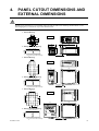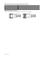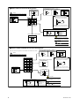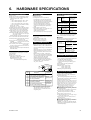
1
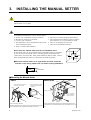
User’s
Manual
Models
UD310, UD320, UD350
Manual Setters
IM 05F01F12-41E
IM 05F01F12-41E
2004.6 3rd Edition
Note: This user’s manual (IM 05F01F12-41E) is a re-edited, A4-size
version of the IM 05F01F12-01E user’s manual that is supplied
along with the product shipped. Therefore, both manuals have the
same contents, except for some minor differences in the crossreferenced page numbers.
Revision Record
●Manual No. : IM 05F01F12-41E(3rd Edition)
●Title
: Models UD310,UD320,UD350 Manual Setters
Revised Item
Edition
First
Date
Feb.,2001
Newly published
Second
Sep.,2003
Correct
Third
Jun.,2004
Change of the company name.
Please read through this user’s manual to ensure correct usage of the manual setter and keep it handy for quick
reference.
CONTENTS
1. Notice ............................................................................................................................... 2
2. What is on the Front Panel? ......................................................................................... 3
3. Installing the Manual Setter ......................................................................................... 4
4. Panel Cutout Dimensions and External Dimensions .................................................. 5
5. Wiring .............................................................................................................................. 6
6. Hardware Specifications ................................................................................................ 9
7. Key Operations ............................................................................................................. 10
8. Troubleshooting ............................................................................................................ 17
■ Checking Package Contents
Before using the product, check that its model & suffix codes are as you ordered.
Model and Suffix Codes
Model
Suffix code
UD310
UD320
UD350
Fixed code
Fixed code
Option
Description
UD310 Manual Setter 4 to 20 mADC output (48⫻48⫻100 mm)
UD320 Manual Setter 4 to 20 mADC output (48⫻96⫻100 mm)
UD350 Manual Setter 4 to 20 mADC output (96⫻96⫻100 mm)
–0
Always 0
0
Always 0
/V24
Power Supply 24V DC / 24V AC
* 2 Alarm outputs and PV retransmission output in 4 to 20 mA built in as standard.
Check the package contents against the list below.
• Manual Setter ..................................... 1
• Mounting bracket ................................ 1 for UD310
2 for UD320, UD350
• User's manual ..................................... 1
IM 05F01F12-41E
1
1.
NOTICE
The following safety symbol is used both on the product and in this user’s manual.
This symbol stands for “Handle with Care.” When displayed on the product, the operator should
refer to the corresponding explanation given in the user’s manual in order to avoid injury or death of
personnel and/or damage to the product. In the manual the symbol is accompanied by an explanation
of the special care that is required to avoid shock or other dangers that may result in injury or loss of
life.
The following symbols are used in this manual only.
Indicates that operating the hardware or software in a particular manner may lead to damage or result in
system failure.
Draws attention to information that is essential for understanding the operation and/or features of the
product.
■ Exemption from Responsibility
Make sure that all of the precautions are strictly adhered to. Yokogawa Electric Corporation assumes no
liability for any damage resulting from use of the instrument in contradiction to the precautions.
Also, Yokogawa Electric Corporation assumes no liability to any party for any loss or damage, direct or
indirect, caused by the use or any unpredictable defect of the instrument.
2
IM 05F01F12-41E
2.
WHAT IS ON THE FRONT PANEL?
UD310
UD320
UD350
a.
a.
a.
c.
b.
c.
c.
b.
UD310
b.
d.
UD350
UD320
e.
e.
d.
e.
d.
■ Monitoring Parts
Name
Function
a.
PV display (red)
Indicates PV (measured value) and character information such as parameter codes and
error codes. PV goes out when the setup parameter ”PVD” is set to OFF.
b.
SP display (green)
Indicates SP (target setpoint) and character information such as parameter setpoints.
c.
AL1, AL2 lamps (red)
AL1 : Lit when alarm 1 is activated.
AL2 : Lit when alarm 2 is activated.
■ Operating Parts (See 7. Key operations)
Name
d.
Data change key
Function
• Changes SP(target setpoint) and the parameter values. Pressing this key increases the
data value.
SP (target setpoint) will be output in 3 seconds after the change.
Holding down the key will gradually increase the speed of changes.
• Changes SP(target setpoint) and the parameter setpoints. Pressing this key decreases the
data value.
SP (target setpoint) will be output in 3 seconds after the change.
Holding down the key will gradually decrease the speed of changes.
SET key
• Registers the parameter setpoint changed using the data change keys.
(parameter data registering key) • Switches between parameter setting displays sequentially.
• Pressing the key for 3 seconds or longer in the operating display retrieves the operating
parameter setting display.
• Pressing the key for 3 seconds or longer in operating or setup parameter setting display
transfers back to operating display.
Data change key
e.
IM 05F01F12-41E
3
3.
INSTALLING THE MANUAL SETTER
To prevent electric shock, the source of power to the manual setter must be turned off when mounting the
manual setter on to a panel.
To install the manual setter, select a location where:
1. No-one may accidentally touch the terminals;
2. Mechanical vibrations are minimal;
3. Corrosive gas is minimal;
4. The temperature can be maintained at about 23°C
with minimal fluctuation;
5. There is no direct heat radiation;
6. There are no resulting magnetic disturbances;
7. The terminal board (reference junction compensation element, etc.) is protected from wind;
8. There is no splashing of water; and
9. There are no flammable materials.
Never place the manual setter directly on flammable items.
If the manual setter has to be installed close to flammable items or equipment,
be sure to enclose the manual setter in shielding panels positioned at least
150mm away from each side. These panels should be made of either 1.43mm
thick metal-plated steel plates or 1.6mm thick uncoated steel plates.
150mm
150mm
150mm
150mm
●Mount the manual setter at an angle within 30° from horizontal
with the screen facing upward. Do not mount it facing downward.
30° (MAX)
■ Mounting the Manual Setter
UD310
Large bracket
(top)
UD320, UD350
Panel
1. Affix the bracket over the back
end of the manual setter.
2. Push the bracket to the panel,
and then secure the bracket
into position.
Terminal board
Panel
Direction for mounting
Insert a screwdriver
into the brackets to
tighten the screws.
UD310
Bracket
Small bracket
(bottom)
[ How to remove the bracket ]
Insert the manual setter into the opening with the terminal board facing the front.
To remove the bracket, push down the center of the upper and lower parts Set and tighten the top and bottom brackets on the manual setter to fix it on the
panel.
of the manual setter softly. The bracket is released from the latch.
4
IM 05F01F12-41E
4.
PANEL CUTOUT DIMENSIONS AND
EXTERNAL DIMENSIONS
Splash-proof construction is not available when the side-by-side close mounting method shown in the
following figures, is chosen for any of the manual setters.
1. General Mounting
max. 44.8
Unit: mm
45 +0.6
0
25
45 +0.6
0
48
12
100
45 +0.6
0
48
max. 44.8
2. Side-by-side Close Mounting
[(N –1) × 48 + 45] +0.6
0
UD310
N is the number of manual setters.
If N > 5, then measure the actual length.
max. 61
min. 70
25
UD310
max. 47.8
min. 70
Panel thickness
1 to 10
1. General Mounting
UD320
53
min. 145
Unit: mm
11
100
max. 91.8
45 +0.6
0
96
25
2. Side-by-side Close Mounting
[(N –1) × 48 + 45] +0.6
0
max. 112
92 +0.8
0
48
max. 44.6
1-1021-301-20
min. 70
92 +0.8
0
UD320
Panel thickness
1 to 10
N is the number of manual setters.
If N > 5, then measure the actual length.
min. 117
UD350
92 +0 0.8
53
min. 145
Unit: mm
+ 0.8
0
96
2. Side-by-side Close Mounting
[(N –1) × 96 + 92] +0.8
0
92 +0.8
0
UD350
max. 112
92
100
max. 91.8
25
11
96
max. 91.8
1-1051-6041-5031-4021-3011-20
1. General Mounting
N is the number of manual setters.
If N > 5, then measure the actual length.
IM 05F01F12-41E
Panel thickness
1 to 10
5
5.
WIRING
1) Before you start wiring, turn off the power source and use a tester to check that the manual setter and
cables are not receiving any power in order to prevent electric shock.
2) For safety, be sure to install a circuit breaker switch (of 5A and 100V AC or 220V AC, and that
conforms to IEC60947) near the instrument so as to be operated easily, and clearly indicate that the
device is used to de-energize the instrument.
3) Wiring should be carried out by personnel with appropriate electrical knowledge and experience.
1) Use a single-phase power source. If the source has a lot of noise, use an isolation transformer for the
primary side and a line filter (we recommend TDK’s ZAC2205-00U product) for the secondary side.
When this noise-prevention measure is taken, keep the primary and secondary power cables well apart.
Since the manual setter has no fuse, be sure to install a circuit breaker switch (of 5A and 100V AC or
220V AC, and that conforms to IEC standards) and clearly indicate that the device is used to de-energize
the manual setter.
2) For thermocouple input, use shielded compensating lead wires. For RTD input, use shielded wires which
have low resistance and no resistance difference between the 3 wires. See the table given later for the
specifications of the cables and terminals and the recommended products.
3) The alarm output relay cannot be replaced even though it has a limited service life (100,000 relay
contacts for the resistance load). Thus, an auxiliary relay should be used so that the load can be turned
on and off.
4) When using an inductive load (L) such as an auxiliary relay and solenoid valve, be sure to insert a CR
filter (for AC) or diode (for DC) in parallel as a spark-rejecting surge suppressor to prevent malfunctions
or damage to the relay.
5) When there is the possibility of being struck by external lightening surge, use the arrester to protect the
insturment.
• Always fix a terminal cover bracket to the UD310 manual setter before wiring if an optional antielectric-shock terminal cover (part number: L4000FB) is used.
• Two types of optional anti-electric-shock terminal covers (part numbers T9115YE and T9115YD) are
available for the UD320 and UD350 manual setters, respectively.
6
IM 05F01F12-41E
● Cable Specifications and Recommended Products
Power supply and relay contact output
600V vinyl insulated wire/cable, JIS C3307, 0.9 to 2.0mm2
Thermocouple input
Shielded compensating lead wire, JIS C1610
RTD input
Shielded wire (3-wire), UL2482 (Hitachi cable)
Other signals
Shielded wire
● Recommended Terminals
Use M3.5 screw-compatible crimp-on terminals with an insulating sleeve, as shown below.
IM 05F01F12-41E
ø 3.7mm
7mm or less
7mm or less
ø 3.7mm
7
■ Model UD310-00 Terminal Arrangement
RTD Input
TC Input
Alarm Outputs
NOTE
Do not use unassigned terminals as relay terminals.
11
ALM2
7
+
12
ALM1
8
–
13
COM
B
7
b
DC mV or V Input
A
7
+
8
–
Receiving 4-20 mA DC Current
Signals with the Manual Setter
* When receiving 4-20 mA DC current signals,
+
4 to 20 mA DC
2
6
8
PV Retransmission Output
1
Universal input-selectable
input type
Measured Value (PV) Input
–
1
11
6
2
12
7
3
13
8
4
14
9
5
15
10
set the PV input type to 1-5 V DC (setpoint “22”).
7 +
250 Ω 4-20mA
8
-
Note: Connecting a 250 Ω resistor to the terminals is
optional.
Model: X010-250-2 (resistor with M3.5 crimp-on terminal
lugs)
Power Supply
9
L
+
9
AC/DC 24V
10
Manual Setting (SP) Output
10 –
N
100-240V AC
4 to 20 mA Output
14
when /V24 option is specifed.
CAUTION
+
To prevent damage to the manual setter,
never provide 100-240V AC power supply
for power supply AC/DC 24V model (when
⬙/V24⬙ is specified).
15 –
NOTE
The + and – stand for the polarity
for DC 24V power supply.
■ Models UD320-00/UD350-00 Terminal Arrangement
Measured Value (PV) Input
Note:The terminal arrangements of the UD320 and UD350 are the same.
RTD Input
TC Input
NOTE
12
+
13
–
Universal input-selectable
input type
12
+
12 b
Do not use unassigned terminals as relay terminals.
Receiving 4-20 mA DC Current
Signals with the Manual Setter
Manual Setting (SP) Output
12
14
14
PV Retransmission Output
250 Ω 4-20mA
+
4 to 20 mA DC
30 –
17
18
29
19
30
20
13 -
15 –
16
28
set the PV input type to 1-5 V DC (setpoint “22”).
12 +
+
15
27
* When receiving 4-20 mA DC current signals,
4 to 20 mA Output
13
26
13 –
13 A
11
29
DC mV or V Input
11 B
Note: Connecting a 250 Ω resistor to the terminals is
optional.
Model: X010-250-2 (resistor with M3.5 crimp-on terminal
lugs)
Alarm Outputs
16
ALM2
17
ALM1
18
COM
CAUTION
To prevent damage to the manual setter,
never provide 100-240V AC power supply
for power supply AC/DC 24V model (when
⬙/V24⬙ is specified).
Power Supply
19
L
19
+
AC/DC 24V
20
N
100-240V AC
8
20 –
when /V24 option is specifed.
NOTE
The + and – stand for the polarity
for DC 24V power supply.
IM 05F01F12-41E
6.
HARDWARE SPECIFICATIONS
Measured Value (PV) Input
•
•
•
•
•
•
•
•
•
•
Power Supply and Isolation
Alarm Functions
1 point
• Input:
type: Universal; can be selected by software
• Input
Input
accuracy
(at 23 ±2°C ambient temperature)
• Thermocouple:
±2°C ±1digit
However,
• ±4°C for thermocouple input –200 to –100°C
• ±3°C for thermocouple input –100 to 0°C
• ±5°C for types R and S (±9°C for 0 to 500°C)
• ±9°C for type B (accuracy is not guaranteed for 0 to 400°C)
• RTD: ±1°C ±1digit
Voltage(mV,
V) : ±0.3% ±1digit
•
Sampling period for measured value input: 500ms
Burn-out detection: Functions for thermocouple or RTD input
(burn-out upscale only; cannot be switched off)
Input resistance: 1MΩ or greater for thermocouple
or DC mV input. Approx. 1MΩ for DC V input
Maximum allowable signal source resistance :
250Ω for thermocouple or DC mV input
2kΩ for DC V input
Maximum allowable wiring resistance for RTD input:
10Ω/wire (The resistance values of three wires must be the same.)
Allowable input voltage: ±10V DC for thermocouple or DC mV input
±20V DC for DC V input
Noise rejection ratio: Normal mode noise: Min. 40dB
(50/60Hz)
Common mode noise: Min. 120dB
(Min. 90dB for DC V input)
Error of reference junction compensation:±1.5°C (at 15-35°C)
±2.0°C (at 0-50°C)
The reference junction compensation cannot be switched off.
Applicable standards:
Thermocouple and resistance temperature detector(RTD)
JIS/IEC/DIN (ITS90)
Manual Setting (SP) Output
SP (target setpoint) will be output in 3 seconds
after the change.
Output: 1 point
Output type: Current output
Output signal: 4 to 20mA current output
Maximum load resistance: 600Ω
Output accuracy: ±0.3% of span
(at 23±2°C ambient temperature)
•
•
■Power Supply
■Alarm Functions
Alarm types: 22 types
• (waiting
action can be set by software):
•
PV high limit, PV low limit, Deviation high
limit, Deviation low limit, De-energized on
deviation high limit, De-energized on deviation
low limit, Deviation high and low limits,
Deviation within high and low limits, Deenergized on PV high limit, De-energized on
PV low limit, Fault diagnosis output, FAIL
output
Alarm output: 2 relay contacts
Relay contact capacity: 1A at 240V AC or 1A
at 30V DC (with resistance load)
(COM terminal is common)
Note: The alarm output relays cannot be replaced by users
Retransmission Output
signal: Measured value in 4-20mA DC,
• Output
can be scaled.
Maximum
load resistance: 600Ω
• Output accuracy:
of span
• (at 23±2°C ambient±0.3%
temperature)
Safety and EMC Standards
Safety: Compliant with IEC/EN61010-1: 2001,
• approved
by CSA1010, approved by UL508.
Installation category : CAT. II (IEC/EN61010,
CSA1010) Pollution degree : 2 (IEC/EN61010,
CSA1010)
Measurement category : I (CAT. I : IEC/EN61010)
Rated measurement input voltage : 10V DC
max.(across terminals), 300V AC max.(across
ground)
Rated transient overvoltage : 1500V (Note)
Note : It is a value on the safety standard which
is assumed by IEC/EN61010-1 in measurement
category I, and is not the value which
guarantees an apparatus performance.
Caution: This equipment has Measurement
category I, therefore do not use the equipment
for measurements within measurement
categories II, III and IV.
Internal Wiring
3
Entrance 4
Cable
Measurement
category
Description
2
Power
supply
Frequency
Maximum power consumption
Memory
Withstanding Between primary terminals
and secondary terminals
voltage
(See Notes 1 and 2.)
Insulation Between primary terminals
resistance and secondary terminals
(See Notes 1 and 2.)
Appliances,
portable equipments,
etc.
For measurements performed in
3 CAT.3 the building installation.
Distribution board,
circuit breaker, etc.
Overhead wire,
For measurements performed at
4 CAT.4 the source of the low-voltage installation. cable systems,
etc.
EMC standards: Complies with EN61326.
• The
instrument continues to operate at a
measuring accuracy of within ±20% of the
range during tests.
20MΩ or more at
500V DC
The bold lines below indicate reinforced isolation, and
the broken line indicates functional isolation.
Power supply
Power supply
terminals AC/DC 24V
terminals
(When ⬙/V24⬙ is specified)
(100-240V AC)
Measured value input
terminals
Internal circuit
Alarm output
Manual setting output
terminals
terminals : 4-20 mA
(2 relay contacts)
Retransmission output
terminals : 4-20 mA
Note: The measured value input terminals is isolated from the
internal circuit.
•
•
•
•
•
•
•
Construction, Mounting, and Wiring
Construction: Dust-proof and drip-proof front
• panel
conforming to IP65 [Model UD310] and
•
•
•
•
For measurements performed on
2 CAT.2 circuits directly connected to the
low voltage installation.
1500V AC
for 1 minute
■ Isolation
T
1 CAT.1 For measurements performed on
circuits not directly connected to MAINS.
8VA max. (4W max.)
3W max. when
⬙/V24⬙ is specified.
Non-volatile memory
Note 1: The primary terminals are the power supply terminals and
alarm output terminals.
The secondary terminals are the analog input and output terminals.
Note 2: AC/DC 24V terminals are secondary terminals.
1
Remarks
Rated at 100-240VAC (±10%)
AC/DC 24V, 20 to 29V of
allowable range when
⬙/V24⬙ is specified.
50 or 60Hz
Voltage
IP55 [Models UD320 and UD350].
For side-by-side close installation the
controller loses its dust-proof and drip-proof
protection.
Casing: ABS resin and polycarbonate
Case color: Black
Weight: UD310 - approx. 200g
UD320 - approx. 300g
UD350 - approx. 400g
Mounting: Flush panel mounting
Environmental Conditions
■Normal Operating Conditions
time: At least 30 minutes
• Warm-up
Ambient temperature:0-50°C (0-40°C when
• mounted
side-by-side)
of change of temperature: 10°C/h or less
• Rate
humidity: 20-90% RH (no condensation allowed)
• Ambient
field: 400A/m or less
• Magnetic
vibrations of 5 to 14Hz: Amplitude of 1.2mm or less
• Continuous
vibrations of 14 to 150Hz: 4.9m/s (0.5G) or less
• Continuous
vibrations: 14.7m/s (1.5G) for 15 seconds or less
• Short-period
98m/s (10G) for 11 milliseconds or less
• Shock:
Mounting
angle: Upward incline of up to 30
• degrees; downward
incline is not allowed.
Altitude: 2000m or less above sea level
•■Maximum
Effects from Operating Conditions
2
2
2
(1) Temperature effects
Thermocouple, DC mV and DC V input: ±2µV/°C
or ±0.02% of F.S./°C, whichever is larger
Resistance temperature detector: ±0.05°C/°C
Analog output: ±0.05% of F.S./°C
(2) Effect from fluctuation of power supply voltage
(within rated voltage range)
Analog input: ±0.2µV/V or ±0.002% of F.S./V,
whichever is larger
Analog output: ±0.05% of F.S. /V
•
•
•
•
•■Transportation and Storage Conditions
–25 to 70°C
• Temperature:
5 to 95% RH (no condensation allowed)
• Humidity:
Shock:
Package
drop height 90cm (when packed in
• the dedicated package)
IM 05F01F12-41E
9
7.
KEY OPERATIONS
To prevent electric shock, the manual setter should be mounted on the panel so as not to accidentally touch
the terminals when power is being applied.
(1)You can move between parameter setting displays using the
key.
(2)To change the parameter setpoint,
or
key (the period flashes).
( i ) Change the display value with the
(ii) Press the
key to register the setpoint.
(3)In the operating display, pressing the
key for at least 3 seconds retrieves the operating parameter setting display.
(4)In the operating parameter setting display, pressing the
key for at least 3 seconds transfers back to the operating display.
Registering the key-lock parameter LOC to “–1” retrieves the setup parameter setting display.
(5)In the setup parameter setting display, pressing the
key for at least 3 seconds transfers back to the operating display.
● UD310/UD320/UD350 Measured Input Type and Ranges
Range code (°C)
Range (°F)
Range code (°F)
OFF
– 270 to 1370 °C
– 300 to 2500 °F
31
1
0.0 to 600.0 °C
32
32.0 to 999.9 °F
2
K
0.0 to 400.0 °C
33
32.0 to 750.0 °F
3
– 199.9 to 200.0 °C
34
– 300 to 400 °F
4
J
– 199.9 to 999.9 °C
35
– 300 to 2100 °F
5
T
– 199.9 to 400.0 °C
36
– 300 to 750 °F
6
E
– 199.9 to 999.9 °C
37
– 300 to 1800 °F
7
R
0 to 1700 °C
38
32 to 3100 °F
8
S
0 to 1700 °C
39
32 to 3100 °F
9
B
0 to 1800 °C
40
32 to 3200 °F
10
N
– 200 to 1300 °C
41
– 300 to 2400 °F
11
L
– 199.9 to 900.0 °C
42
– 300 to 1600 °F
12
U
– 199.9 to 400.0 °C
43
– 300 to 750 °F
13
Platinel 2
0 to 1390 °C
44
32 to 2500 °F
14
– 199.9 to 850.0 °C
45
– 199.9 to 999.9°F
15
0.0 to 400.0 °C
46
32.0 to 750.0 °F
16
Pt100
– 199.9 to 200.0 °C
47
– 300 to 400 °F
17
– 19.9 to 99.9 °C
48
– 199.9 to 999.9°F
18
JPt100
– 199.9 to 500.0 °C
19
0 to 100mV 0.0 to 100.0
20
0 to 5V 0.000 to 5.000
21
User-scalable
1 to 5V 1.000 to 5.000
22
0 to 10V 0.00 to 10.00
23
DC voltage
RTD
Thermocouple
Input type
Unspecifed
Range (°C)
UD310
For example, to select
thermocouple type J (°F),
set the range code to 35.
At power-on, the manual setter displays the operating display, but if the measured input type setting
key to display the measured input range code
remains OFF, “IN” appears. In this case, press the
you want to use, then press the
key to register it. (Refer to the flowchart below.)
10
IM 05F01F12-41E
The manual setter is shipped with the parameters set at the factory-set defaults. Check the default values
against the “Parameter Lists” in the page 13 and 14, and change the parameter setpoints that need to be
changed.
This section explains how to set and register parameter setpoints.
The procedure for changing Target Setpoint(SP) and Alarm 1 Setpoint(A1) can be found on "Changing Target Setpoint(SP)"
and "Changing Alarm 1 Setpoint(A1)".
You can set the other parameters in the same way.
■ Changing Target Setpoint (SP)
■ Changing Alarm 1 Setpoint (A1)
The following instructions assume that the manual
setter is already receiving power.
SP (target setpoint) value will be output in 3
seconds after the change.
Step 1:
Confirm that the manual setter
shows the operating display
during normal operation (PV
and SP are displayed on the
indicators).
Step 2:
Press the
or
key to
change the SP display value to
the required setpoint. In this
example, SP is changed to
200°C.
Check alarm type before setting the alarm setpoint.
Factory-set settings:
Alarm 1 type : OFF
Alarm 2 type : OFF
Step 1:
Confirm that the manual setter
shows the operating display
during normal operation (PV
and SP are displayed on the
indicators).
UD310
UD310
Step 2:
To enter the operating parameter
setting display, press the
key
for at least 3 seconds.
UD310
UD310
Press for at least 3 seconds.
Step 3:
Press the
or
key to
change the current A1 setpoint
to a required setpoint. In this
example, A1 is changed to
200°C.
Minimum value
of measured input
range (scale)
Maximum value
of measured input
range (scale)
The period flashes while the setpoint is being changed.
Measured input range
SPH
SPL
Target setpoint range
(Factory-shipped settings)
SPL
SPH
Target setpoint range
(after scaling)
4mA
Manual setting output
(4 to 20mA)
UD310
20mA
Step 4:
Press the
key once to
register the setpoint.
The period goes out.
A1 is now changed.
Another press of the
key calls up the Alarm 2
setpoint(A2) display.
To return to the operating
display, press the
UD310
The period goes out.
key for at least 3 seconds.
Changing certain setup parameter may atomatically initialize the operating parameters. Therefore, after you
change the setup parameters, always check the operating parameter setpoints to find out if appropriate
values have been set for them. If the operating parameters have been initialized, set them to their appropriate values.
IM 05F01F12-41E
11
Power ON
A
NOTE
At first
When measured input range code has been already set,
the operating display shown below appears.
No
Yes
is displayed
?
Operating Display
UD310
Measured input
value(PV)
TIP
Set the parameters
as follows not to
display a measured
input value.
No display
Target setpoint(SP)
Measured input type (IN):
DC voltage input (20 to 23)
Target setpoint(SP)
UD310
UD310
When parameter PVD=ON
(factory-set default)
PV/SP display (PVD)
: OFF
When parameter PVD=OFF
When “In” appears, press the
key to display the measured input
range code you want to use, then
press the
key to register it.
After this operation, the manual
setter shows the operating
display.
A
Note
Press the
key for
at least 3 seconds.
(To operating
display)
Press the
key
for at least
3 seconds.
Operating Parameter Setting Display
Press the
key
to move
between items.
Press the
key for
at least 3 seconds.
(To operating
display)
Note
Note: If no key is pressed for a period
of two minutes or more while in
the operating or setup parameter
setting display, the manual setter
automatically returns to operating
display.
Setup Parameter Setting Display
IN
A1
A2
FL
BS
LOC
LOC=
• Displayed when AL1, AL2 = 1 to 20
When LOC=–1,
transfers to the
setup parameter
setting display
Press the
key
to move
between items.
DP
RH
RL
Displayed when DC voltage
input range code (20 to 23)
is set
SPH
SPL
RTH
RTL
When
–1
NOTE
Set ⬙-1⬙ to enter the setup parameter setting
display. But if ⬙LOC=1 or 2⬙ is already set, the
parameter value can not be changed by setting
⬙LOC=-1⬙ only. To change the parameter value,
set ⬙LOC=0⬙ at first (for disabling keylock),
then set ⬙LOC=-1⬙ once again.
AL1
AL2
HY1
HY2
PVD
NOTE
Changing certain setup parameters may
automatically initialize the operating
parameters. Therefore, after you change the
setup parameters, always check the operating
parameter settings to find out if appropriate
values have been set for them. If the operation
parameters have been initialized, set them to
their appropriate values.
12
IM 05F01F12-41E
■ Parameter Lists
(1) Operating Parameters : Parameters changed rather frequently during operation.
Code
A1
A2
FL
Name
Alarm 1
setpoint
Alarm 2
setpoint
PV input
filter
Setting range and unit
■ PV alarm Unit: °C/°F
Setting range: [minimum value - (maximum value minimum value)] to maximum value of measured
input range (scale)
■ Deviation alarm Unit: °C/°F
Setting range: –100 to 100% of the measured input
range (scale) span
Default
User setting
Depends on the
alarm 1 type.
Depends on the
alarm 2 type.
OFF, 1 to 120 seconds
This function should be used when the PV display
value may fluctuate greatly, for example, when the
measured input signal contains noise. The filter is of
the first-order lag type, and FL sets the time constant.
If a larger time constant is set, the filter can remove OFF
more noise.
Input
2-seconds filter
10-seconds filter
–100 to 100% of measured input range (scale) span
This function adds a bias value to the measured input value,
and the result is used for display and retransmission output.
BS
PV input
bias
PV value inside the manual setter
= measured input value + PV input bias
0% of measured
input range
(scale) span
This function is useful for carrying out fine adjustment when
the PV value is within the required accuracy but it differs from
the value obtained by other equipment.
Key lock
LOC
IM 05F01F12-41E
0: No key lock
1: Prevents parameter from being changed of except
for SP in the operating display.
2: Prevents all parameter changing operations
including SP in the operating display.
–1: Set ⬙-1⬙ to enter the setup parameter setting
display.
But if ⬙LOC=1 or 2⬙ is already set, the parameter
value can not be changed by setting ⬙LOC=-1⬙ only.
To change the parameter value, set ⬙LOC=0⬙ at first
(for disabling keylock), then set ⬙LOC=-1⬙ once
again.
0
13
(2) Setup Parameters : Parameters rarely changed in normal use after once having been set.
Code
Name
Setting range and unit
Default
Measured
input type
1 to 23, 31 to 48 (See input range code list.)
OFF: No input
(If no input type is specified at the time of ordering, you must set the
input type.)
DP
Decimal
point
position of
measured
input
0: No decimal place (nnnn)
1: One decimal place (nnn.n)
2: Two decimal places (nn.nn)
3: Three decimal places (n.nnn)
(RL + 1) to 9999
RH
Maximum
value of
measured
input scale
–1999 to (RH –1)
RL
Minimum
value of
measured
input scale
IN
User setting
OFF, or the input
range code
specified with
order
(Displayed at voltage input)
1
(Displayed at voltage input)
100.0
(Displayed at voltage input)
0.0
SPH setting range:
(SPL+1digit) to the maximum value of the measured
input range (scale) ; Unit: °C/°F
SPH
Maximum
value of target SPL setting range:
setpoint range Minimum value of the measured input range (scale) to
(SPH –1digit) ; Unit: °C/°F
(Setpoint for
Minimum value
Maximum value
manual setting
of measured input
of measured input
range (scale)
range (scale)
output 20mA)
Maximum value
of measured input
range (scale)
Measured input range
SPH
SPL
SPL
Minimum
value of target
setpoint range
Target setpoint range
(Factory-set default)
(Setpoint for
manual setting
output 4mA)
Target setpoint range
(after scaling)
SPL
SPH
4mA
20mA
Minimum value
of measured input
range (scale)
Manual setting output
(4 to 20mA)
Temperature input : Within measured input range
RTH
Voltage input : (RTL+1digit) to max. value of measured
Maximum
input scale(RH)
Maximum value of
value of
Min. value of measured input scale(RL) to (RTH-1digit) measured input
retransmission However, RTL<RTH
range (scale)
output
Minimum value
of measured input
range (scale)
Maximum value
of measured input
range (scale)
Measured input range
RTH
RTL
Retransmission range
(Factory-set default)
RTL
Minimum
value of
retransmission
output
RTL
RTH
4mA
20mA
Retransmission range
(after scaling)
Minimum value of
measured input
range (scale)
Retransmission output
(4 to 20mA)
Alarm 1 type
AL1
OFF
OFF or a value from 1 to 22 (see the table of alarm
function list), and either
Alarm 2 type
OFF
Alarm 1
hysteresis
0.5% of measured
input range
(scale) span
AL2
HY1
HY2
0.0 to 100.0% of measured input range (scale) span
Unit: °C/°F
Alarm 2
hysteresis
0.5% of measured
input range
(scale) span
ON: Displays PV (measured input) and SP (target setpoint)
OFF: Displays SP (target setpoint)
Measured input(PV)
PV/SP
display
Factory-shipped setting
(PVD=ON)
Target setpoint(SP)
UD310
ON
No display
PVD
(PVD=OFF)
Even if a measured input
(PV) is not displayed,
the PV retransmission
ouptut and the alarm
action work normally.
14
Target setpoint(SP)
UD310
IM 05F01F12-41E
Description of Measured Input
Example of Temperature Input
-270°C
Minimum value
of measured
input range
Measured Input Range
Example of Voltage Input
1370°C
Maximum value
of measured
input range
1V
1370°C
RL
5V (input signal)
Measured Input Range
Measured Input Scale
Display Scale
-270°C
RH
Maximum value
of measured input
scale (RH)
200.0°C
Minimum value
of measured input
scale (RL)
0.0°C
Parameters to be set for temperature input.
1. Measured input type (IN) : Set according to a sensor.
Parameters to be set for voltage input.
1. Measured input type (IN) : Set according to an input signal.
2. Decimal point position of measured input (DP) :
Set the position of the decimal point for measured input display.
3. Maximum value of measured input scale (RH) :
Set the maximum value of the scale.
(Set the display value at maximum value of input signal.)
4. Minimum value of measured input scale (RL) :
Set the minimum value of the scale.
(Set the display value at miminum value of input signal.)
Note : Display scale can not be changed.
Description of Alarm Functions
■ Alarm Function List
Alarm
type code
Action
Alarm type
“Opn” and “Cls” indicate that the relay contact is
opened and closed; “(on)” and “(off)” indicate that
the lamp is on and off; and white triangles indicate
temperature setpoints.
Closed contact Open contact
during alarm during alarm
No alarm
OFF
Hysteresis
PV
high limit
Opn (off)
Cls (on)
PV
low limit
Cls (on)
De-energized
on deviation
low limit
11
(See note.)
2
Deviation
high and low
limit
Opn (off)
Alarm setting
6
Opn (on)
Measured value
12
(See note.)
3
Opn (off)
Deviation setting
Measured value
Temperature setpoint
13
(See note.)
Opn
(off)
Temperature setpoint
Hysteresis
Hysteresis
Cls (on)
Opn (off)
Measured value
Temperature setpoint
14
(See note.)
Hysteresis
De-energized
on deviation
high limit
De-energized
on PV
high limit
Opn (off)
Deviation setting
Cls (off)
5
15
(See note.)
Deviation setting
Measured value
Deviation setting
Temperature setpoint
Cls
(off)
9
Opn (on)
19
(See note.)
Alarm setting
Opn (on)
10
Cls (off)
Alarm setting
20
(See note.)
Measured value
The output contact is opened in the following events:
The contact is closed at input
burnout.
Note: The alarms numbered 1 to 10 have no waiting
action, while alarms 11 to 20 have a waiting
action.
The waiting action turns off the PV and deviation
alarms that occur from the start of the control
operation until a stable state is reached.
21
FAIL
output
• Program error
• ROM error
• RAM error
• power failure
°C
Waiting action
Taken as
normal.
• A/D converter error
• RJC error
• EEPROM error
Normal
22
Abnormal
Alarm output = ON
Low limit alarm
setpoint
In this area, the alarm output is turned
off even when a measured value falls
below the low limit alarm setpoint.
Power-on
IM 05F01F12-41E
18
(See note.)
Hysteresis
De-energized
on PV
low limit
Temperature setpoint
Fault
diagnosis
alarm
8
Opn (off)
Measured value
Opn (on)
Measured value
17
(See note.)
Hysteresis
4
Cls (on)
Cls
(on)
Measured value
Deviation setting
Hysteresis
Deviation
low limit
Hysteresis
7
Cls
(on)
Deviation
within highand -lowlimit
Cls (on)
16
(See note.)
Deviation setting
Measured value
Temperature setpoint
Hysteresis
Deviation
high limit
Cls (off)
Hysteresis
Hysteresis
Closed contact Open contact
during alarm during alarm
Hysteresis
1
Measured value Alarm setting
Alarm
type code
Action
“Opn” and “Cls” indicate that the relay contact is
opened and closed; “(on)” and “(off)” indicate that
the lamp is on and off; and white triangles indicate
temperature setpoints.
Alarm type
Time
15
Description of Alarm hysteresis
The alarms are output as relay outputs. Since a relay has a limited service life, excessive on/off actions will
shorten the life of the relay. To prevent this, you can set a hysteresis for both alarm 1 and alarm 2 to moderate
excessive on/off actions.
< PV High Limit Alarm >
HY1 : 15°C
HY1 : 5°C
Relay contact is closed (ON)
Relay contact
is opened
Temperature
Relay contact
is opened
Alarm 1 setpoint : 100°C
Measured input
value (PV)
Alarm ON
Relay contact is closed (ON)
Temperature
Alarm 1 setpoint : 100°C
Measured input
valued (PV)
OFF
ON
Alarm ON
OFF
ON
OFF
OFF
time
16
time
IM 05F01F12-41E
8.
TROUBLESHOOTING
In the event of an abnormality, perform the following checks as outlined by the flowchart.
Is the manual setter defective?
Yes
No
Completely inactive?
Key operation failure?
Yes
Yes
Check the terminal connection
of the power supply
Check key-lock
setting
No
Display failure?
Yes
Turn the power off,
then on
Check the power
supply voltage
Normal?
No
I/O signal failure?
No
Yes
Verify the I/O spec.
of manual setter
Verify the spec. of
I/O destinations
No
No
Yes
Correct it
No
Normal?
Yes
Contact us for repair
Is the key
locked?
Yes
Cancel the setting
Problem solved
■ Error Display during Operation
(1) If the manual setter displays one of the following, carry out the appropriate remedy for the particular error.
Display
Error content
P.Er
B.o
OOO
UUU
No PV display
The parameter is abnormal
Input burnout
Remedy
Check the setpoints of all the parameters and set them
at their proper values.
Check the sensor wiring and correct it.
Not display when the setup parameter PVD=OFF.
PV over-scale
(PV exceeds its effective range.) Check the measured input type and scale settings and
correct them.
PV under-scale
Not display when the setup parameter PVD=OFF.
(PV falls below its effective range.)
Set the setup parameter PVD=ON to display PV.
(2) The manual setter needs to be repaired if any of the indications in the table below appear.
In these cases, do not try to repair the manual setter yourself.
Order a new manual setter or contact us for repair.
Display
Unknown (at power-on)
All extinguished (at power-on)
“Err” (at power-on)
Error content
CPU failure
Power source failure
Calibration abnormal
Error content
Display
Flashing “Err” (at power-on) RAM or ROM failure
Flashing “Err”
A/D converter failure,
(during operation)
RJC failure, or EEPROM failure
■ When Power Failure Occurred during Operation
● Momentary power failures shorter than 20ms (or shorter than 1ms when ⬙/V24⬙ is specified). have no effect
on the manual setter operation (i.e., normal operation continues).
● For power failures of 20ms or longer(or 1ms or longer when ⬙/V24⬙ is specified), however the status will be
as follows.
(The manual setter action at power recovery is the same as at power-on.)
• Alarm action: Continues (but alarms with a waiting action enter the waiting state once)
• Setting parameters : Maintained
IM 05F01F12-41E
17
Blank Page
IM 05F01F12-41E
YOKOGAWA ELECTRIC CORPORATION
Network Solutions Business Division
2-9-32, Nakacho, Musashino-shi, Tokyo, 180-8750 JAPAN
Phone: +81-422-52-7179 Facsimile: +81-422-52-6793
Sales Branch Offices
Tokyo, Nagoya, Osaka, Hiroshima, Fukuoka
YOKOGAWA CORPORATION OF AMERICA
Headquaters
2 Dart Road, Newnan, GA. 30265-1094 U.S.A.
Phone: +1-770-253-7000 Facsimile: +1-770-251-0928
Sales Branch Offices / Texas, Chicago, Detroit, San Jose
YOKOGAWA EUROPE B. V.
Headquaters
Databankweg 20, 3821 AL Amersfoort THE NETHERLANDS
Phone: +31-334-64-1611 Facsimile: +31-334-64-1610
Sales Branch Offices / Houten (The Netherlands), Wien (Austria), Zaventem
(Belgium), Ratingen (Germany), Madrid (Spain), Bratislava (Slovakia), Runcorn (United
Kingdom), Milano (Italy), Velizy villacoublay(France), Johannesburg(Republic of South
Africa)
YOKOGAWA AMERICA DO SUL S.A.
Headquarters & Plant
Praca Acapulco, 31-Santo Amaro, Sao Paulo/SP, BRAZIL CEP-04675-190
Phone: +55-11-5681-2400 Facsimile: +55-11-5681-4434
YOKOGAWA ENGINEERING ASIA PTE. LTD.
Head office
5 Bedok South Road, Singapore 469270 SINGAPORE
Phone: +65-6241-9933 Facsimile: +65-6241-2606
YOKOGAWA ELECTRIC KOREA CO., LTD.
Seoul Sales office
395-70, Shindaebang-dong, Dongjak-gu, Seoul,156-010, KOREA
Phone: +82-2-3284-3000 Facsimile: +82-2-3284-3019
YOKOGAWA TAIWAN CORPORATION
Head office
17F, No.39, Sec. 1, Chung Hwa Road Taipei, 100 TAIWAN
Phone: +886-2-2314-9166 Facsimile: +886-2-2314-9918
YOKOGAWA AUSTRALIA PTY. LTD.
Head office
Centrecourt D1, 25-27 Paul Street North, North Ryde, N. S. W. 2113, AUSTRALIA
Phone: +61-2-9805-0699 Facsimile: +61-2-9888-1844
YOKOGAWA INDIA LTD.
Head office
40/4 Lavelle Road, Bangalore, 560 001, INDIA
Phone: +91-80-227-1513 Facsimile: +91-80-227-4270
LTD. YOKOGAWA ELECTRIC
Grokholskiy per. 13, Build. 2, 4th Floor, 129010, Moscow, RUSSIA FEDERATION
Phone: +7-095-737-7868 Facsimile: +7-095-737-7869